FMVSS209中文版
美国DOT汽车安全技术法规资料(FMVSS)
DOT认证制度美国汽车安全技术法规FMVSS美国是世界上法律法规体系最完备的国家之一,政府从维护整个社会和公众的利益出发,将汽车产品的设计与制造纳入社会管理的法律体系中,对汽车产品的设计和制造专门立法,授权汽车安全、环保、防盗和节能的主管部门制定汽车技术法规,并按照汽车技术法规对汽车产品实施法制化的管理制度,实现政府对汽车产品在安全、环保、防盗和节能方面的有效控制。
美国联邦政府根据国会通过的有关法律,如《国家交通及机动车安全法》《机动运载车法》《机动车情报和成本节约法》《噪声控制法》《大气污染防治法》及《机动车辆防盗法实施令》等为依据,分别授权美国运输部(Dot)和美国环境保护署(EPA)制定并实施有关汽车安全、环保、防盗和节能方面的汽车法规,以达到政府对汽车产品安全、环保、防盗和节能这几方面有效的控制。
本文现专门就美国汽车安全技术法规的制修订和实施工作的最新发展情况进行介绍。
1.美国联邦机动车安全标准(FMVSS)1966年9月,美国颁布实施《国家交通及机动车安全法》,授权美国运输部(DOT)对乘用车、多用途乘用车、载货车、挂车、大客车、学校客车、摩托车,以及这些车辆的装备和部件制定并实施联邦机动车安全标准(Federal Motor Vehicle Safety Standards.简称FMVSS)。
任何车辆或装备部件如果与FMVSS不符合,不得为销售的目的而生产,不得销售或引入美国州际商业系统,不得进口。
根据目前《国家交通及机动车安全法》最新修订本的规定,对违反此法要求的制造商或个人,美国地区法院(district court)最高可以处以1500万美元罚款的民事处罚,对造成人员死亡或严重身体伤害的机动车或装备安全缺陷隐瞒不报,或制造虚假报告的制造商将追究刑事责任,最高刑事处罚为15年有期徒刑。
在美国《国家交通及机动车安全法》的授权下,由美国运输部国家公路交通安全管理局具体负责制定、实施联邦机动车安全标准,它们都被收录在"联邦法规集"(Code of Federal Regulation, 简称CFR)第49篇第571部分。
美国汽车安全技术法规(FMVSS)介绍

美国汽车安全技术法规(FMVSS)介绍2010年美国汽车安全技术法规(FMVSS)目录CFR第49卷第571部分。
目前共计63项。
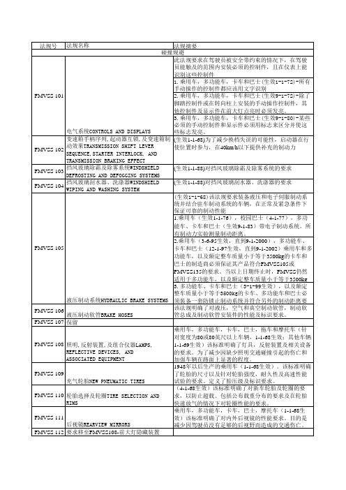
序号法规名称页码范围1.FMVSS 101 控制器和显示器 233~2432.FMVSS 102 变速器换挡杆顺序, 起动机互锁机构和变速器制动效能 243~2443.FMVSS 103风窗玻璃除霜和除雾系统 244~2454.FMVSS 104风窗玻璃刮水和洗涤系统 245~2475.FMVSS 105液压制动系统 247~2676.FMVSS 106制动软管 267~2997.FMVSS 108灯具,反射装置和辅助设备 299~4808.FMVSS 109新的充气轮胎 480~4909.FMVSS 110轮胎和轮辋选择 490~50010.FMVSS 111后视镜 501~51011.FMVSS 113罩盖锁装置 51012.FMVSS 114防盗装置 510~51213.FMVSS 116机动车制动液 512~53414.FMVSS 117翻新充气轮胎 534~53515.FMVSS 118动力操纵车窗系统 536~54116.FMVSS 119车辆(不包括轿车)用的充气轮胎 541~54617.FMVSS 120机动车(不包括轿车)轮胎和轮辋选择 546~55218.FMVSS 121气压制动系统 552~57419.FMVSS122 摩托车制动系统 574~58120.FMVSS 123摩托车的控制器和显示器 582~58521.FMVSS 124加速器控制系统 58622.FMVSS 125警告装置 586~59123.FMVSS 126 汽车电子稳定控制系统 591~60224.FMVSS 129新的轿车非充气轮胎 602~60825.FMVSS 131学童客车行人安全装置 609~61126.FMVSS 135轿车制动系统 611~63127.FMVSS 138 轮胎气压监控系统 631~63628.FMVSS 139 轻型车辆新气压轮胎 636~64329.FMVSS 201乘员在车内碰撞时的防护 643~66330.FMVSS 202头枕 663~66631.FMVSS 202a头枕 666~68132.FMVSS 203驾驶员免受转向控制系统伤害的碰撞保护681~68233.FMVSS 204转向控制装置的向后位移 682~68334.FMVSS 205玻璃材料 683~68535.FMVSS 205(a) 玻璃材料 685~69136.FMVSS 206车门锁及车门固定组件 691~71037.FMVSS 207座椅系统 710~71438.FMVSS 208乘员碰撞保护 715~80639.FMVSS 208a 2004年1月27日至2004年8月31日期间生产车辆的可选实验规程 807~82840.FMVSS 209座椅安全带总成 828~84641.FMVSS 210座椅安全带总成固定点 846~85442.FMVSS 212风窗玻璃的安装 854~85543.FMVSS 213儿童约束系统 855~89844.FMVSS 214侧碰撞保护 898~92445.FMVSS 216轿车车顶抗压强度 924~92846.FMVSS 216a轿车车顶抗压强度,升级版标准 928~93347.FMVSS 217客车紧急出口及车窗的固定与松放 933~95148.FMVSS 218摩托车头盔 951~96749.FMVSS 219风窗玻璃区的干扰 967~96950.FMVSS 220学童客车倾翻的防护 969~97051.FMVSS 221学童客车的车身联结强度 971~97352.FMVSS 222学童客车乘员座椅和碰撞保护 973~99153.FMVSS 223后碰撞防护装置 991~99654.FMVSS 224后碰撞保护 996~99955.FMVSS 225 儿童约束系统固定点 999~103656.FMVSS 301燃料系统的完整性 1036~104457.FMVSS 302汽车内饰材料的燃烧特性 1045~104758.FMVSS 303压缩天燃气车辆燃料系统的完整性 1047~105059.FMVSS 304压缩天燃气车辆燃料箱的完整性 1050~105360.FMVSS 305 电动车辆—电解液溅出及电击保护 1053~105861.FMVSS 401乘用车行李厢内部开启机构 1058~105962.FMVSS 403 机动车辆地板举升系统 1059~107963.FMVSS 404 机动车辆地板举升器的安装 1079~108064.FMVSS 500 低速车辆(车速介于20mph--35mph的4轮车辆) 1080~1081。
FMVSS中文版
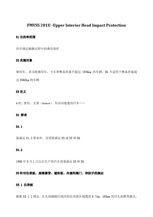
FMVSS 201U -Upper Interior Head Impact ProtectionS1目的和范围旨在规定碰撞过程中的乘员保护S2实施对象乘用车、多功能乘用车、卡车和整备质量不超过4536kg的车辆。
S6不适用于整备质量超过3860kg的车辆S3定义A柱、B柱、支架(brace)、有活动遮篷的汽车……S4 要求S4.1除满足S4.2要求外,还需要满足S5或S5和S6S4.21998年9月1日以后生产的汽车需要满足S5和S6S5针对仪表板、座椅靠背、遮阳板、内部间隔门、和扶手的规定S5.1 仪表板根据S5.1.2规定,在头部碰撞区域内的仪表盘区域遭到6.7kg、165mm直径头部模型撞击,撞击速度为:(a)除了b规定的车辆以外的所有车辆,相对速度为24km/h(b)对于利用安全气囊约束系统满足49 CRF 571.208的S5.1乘员碰撞保护规定和利用针对指定右前配有2型安全带的乘坐位置满足S4.1.5.1(a)(3)要求的车辆,相对速度为19km/h,头部减速度不能连续高于80g超过3ms。
S5.1.1S5.1不适用于(a)操作台装配件(b)从仪表盘附件连接处到车身内部结构距离小于125mm(c)距离挡风玻璃接缝比正常位置下静止时头部模型可接触挡风玻璃的区域更近的区域(d)(e)S5.1.2 示范过程要根据美国工程师协会推荐的J921进行试验。
“仪表盘实验室冲击试验”,1965年6月,用制定的试验设备或者满足美国工程师协会推荐试验J977要求的试验设备,“实验室冲击试验设备”,1966年9月,除了:(a)仪表盘表面的切线端点应该在距离穿过前排外侧乘客制定乘坐位置的参考点水平方向(-X)125mm的横向水平线上,垂直向上移动19mm或者是座椅向前移动125mm引起的垂直位移;而且(b)冲击方向是:(1)平行于车辆纵向轴线的垂直面上,或者(2)在接触点垂直于表面的平面上。
S5.2座椅靠背除了像在S5.2.1中提到的,当位于头部冲击区域内的靠背区域受到(和S5.2.2一致)6.8kg、165mm直径的头部模型以24km/h的相对速度冲击时,头部模型的减速度超过80g时间不能超过3ms。
美国DOT汽车认证检测项目及法规列表(中英文)

FMVSS 103
FMVSS 104
FMVSS 111
FMVSS 105
FMVSS 106
FMVSS 116
FMVSS 121
FMVSS 135
FMVSS 109
FMVSS 110
FMVSS 117
FMVSS 119
FMVSS 120
FMVSS 129
FMVSS 138
FMVSS 125
FMVSS 108
Regulation list of FMVSS 联邦机动车安全标准清单
No 序号 1 Controls and displays 控制器和显示器 2 Winshield defrostting and defogging system 风窗玻璃除霜和除雾系统 3 Winshield wiping and washing system 风窗玻璃刮水和洗涤系统 4 Rear mirrors 后视镜 5 Hydralic brake system 液压制动系统 6 Brake hoses 制动软管 7 Motor vehicle brakefluid 机动车制动液 8 Air brakesystem 气压制动系统 9 Light vehicle brake system 轿车制动系统 10 New pneumatic tires 新的充气轮胎 11 Tire selection and rims 轮胎和轮辋选择 12 Retreated pneumatic tires 翻新充气轮胎 13 Vehicle(exclude car) pneumatic tires 车辆(不包括轿车)用的充气轮胎 14 Vehicle(exclude car) tire selection and rims 机动车(不包括轿车)轮胎和轮辋选择 15 New non-pneumatic tires for passenger-car 新的轿车非充气轮胎 16 Tire pressure monitoring system 轮胎气压监控系统 17 Warning devices 警告装置 18 Lamps, reflective devices, and associated equipment 灯具,反射装置和辅助设备 19 Hood latch system 罩盖锁装置 20 Theft protection 防盗装置 21 School bus pedestrian safety devices 学童客车行人安全装置 22 Accelerator control systems 加速器控制系统汽车工程 23 Transmission shift lever sequence, starter interlock, and transmission braking effect Subject 项目 Standard NO. 标准号 FMVSS 101
FMVSS209标准

§ 571.209 Standard No. 209; Seat belt assemblies.S1. Purpose and scope. This standard specifies requirements for seat belt assemblies.S2. Application. This standard applies to seat belt assemblies for use in passenger cars, multipurpose passenger vehicles, trucks, and buses.S3. Definitions. Adjustment hardware means any or all hardware designed for adjusting the size of a seat belt assembly to fit the user, including such hardware that may be integral with a buckle, attachment hardware, or retractor.Attachment hardware means any or all hardware designed for securing the webbing of a seat belt assembly to a motor vehicle.Automatic-locking retractor means a retractor incorporating adjustment hardware by means of a positive self-locking mechanism which is capable when locked of withstanding restraint forces.Buckle means a quick release connector which fastens a person in a seat belt assembly.Emergency-locking retractor means a retractor incorporating adjustment hardware by means of a locking mechanism that is activated by vehicle acceleration, webbing movement relative to the vehicle, or other automatic action during an emergency and is capable when locked of withstanding restraint forces.Hardware means any metal or rigid plastic part of a seat belt assembly.Load-limiter means a seat belt assembly component or feature that controls tension on the seat belt to modulate the forces that are imparted to occupants restrained by the belt assembly during a crash.Nonlocking retractor means a retractor from which the webbing is extended to essentially its full length by a small external force, which provides no adjustment for assembly length, and which may or may not be capable of sustaining restraint forces at maximum webbing extension.Pelvic restraint means a seat belt assembly or portion thereof intended to restrain movement of the pelvis.Retractor means a device for storing part or all of the webbing in a seat belt assembly.Seat back retainer means the portion of some seat belt assemblies designed to restrict forward movement of a seat back.Seat belt assembly means any strap, webbing, or similar device designed to secure a person in a motor vehicle in order to mitigate the results of any accident, including all necessary buckles and other fasteners, and all hardware designed for installing such seat belt assembly in a motor vehicle.Strap means a narrow nonwoven material used in a seat belt assembly in place of webbing.Type 1 seat belt assembly is a lap belt for pelvic restraint.Type 2 seat belt assembly is a combination of pelvic and upper torso restraints.Type 2a shoulder belt is an upper torso restraint for use only in conjunction with a lap belt as a Type 2 seat belt assembly.Upper torso restraint means a portion of a seat belt assembly intended to restrain movement of the chest and shoulder regions.Webbing means a narrow fabric woven with continuous filling yarns and finished selvages.S4. Requirements.S4.1(a) Incorporation by reference. SAE Recommended Practice J211–1 rev. December 2003, “Instrumentation for Impact Test—Part 1—Electronic Instrumentation,” is incorporated by reference in S5.2(j) and is hereby made part of this Standard. This incorporation by reference was approved by the Director of the Federal Register in accordance with 5 U.S.C. 552(a) and 1 CFR Part 51. Copies of SAE Recommended Practice J211–1 rev. December 2003, “Instrumentation for Impact Test—Part 1—Electronic Instrumentation” may be obtained from the Society of Automotive Engineers, Inc., 400 Commonwealth Drive, Warrendale, PA 15096–0001. Copies may be inspected at the National Highway Traffic Safety Administration, Technical Information Services, 400 Seventh Street, SW., Plaza Level, Room 403, Washington, DC 20590, or at the National Archives and Records Administration (NARA). For information on the availability of this material at NARA, call (202) 741–6030, or go to: /federal_register/code_of_federal_regulations/ibr_locations.html.(b) Single occupancy. A seat belt assembly shall be designed for use by one, and only one, person at any one time.(c) Upper torso restraint. A Type 2 seat belt assembly shall provide upper torso restraint without shifting the pelvic restraint into the abdominal region. An upper torso restraint shall be designed to minimize vertical forces on the shoulders and spine. Hardware for upper torso restraint shall be so designed and located in the seat belt assembly that the possibility of injury to the occupant is minimized.A Type 2a shoulder belt shall comply with applicable requirements for a Type 2 seat belt assembly in S4.1 to S4.4, inclusive.(d) Hardware. All hardware parts which contact under normal usage a person, clothing, or webbing shall be free from burrs and sharp edges.(e) Release. A Type 1 or Type 2 seat belt assembly shall be provided with a buckle or buckles readily accessible to the occupant to permit his easy and rapid removal from the assembly. Buckle release mechanism shall be designed to minimize the possibility of accidental release. A buckle with release mechanism in the latched position shall have only one opening in which the tongue can be inserted on the end of the buckle designed to receive and latch the tongue.(f) Attachment hardware. A seat belt assembly shall include all hardware necessary for installation in a motor vehicle in accordance with Society of Automotive Engineers Recommended Practice J800c, “Motor Vehicle Seat Belt Installation,” November 1973. However, seat belt assemblies designed for installation in motor vehicles equipped with seat belt assembly anchorages that do not require anchorage nuts, plates, or washers, need not have such hardware, but shall have 7/16–20 UNF–2A or 1/2–13UNC–2A attachment bolts or equivalent metric hardware. The hardware shall be designed to prevent attachment bolts and other parts from becoming disengaged from the vehicle while in service. Reinforcing plates or washers furnished for universal floor, installations shall be of steel, free from burrs and sharp edges on the peripheral edges adjacent to the vehicle, at least 1.5 mm in thickness and at least 2580 mm 2 in projected area. The distance between any edge of the plate and the edge of the bolt hole shall be at least 15 mm. Any corner shall be rounded to a radius of not less than 6 mm or cut so that no corner angle is less than 135° and no side is less than 6 mm in length.(g) Adjustment. (1) A Type 1 or Type 2 seat belt assembly shall be capable of adjustment to fit occupants whose dimensions and weight range from those of a5th-percentile adult female to those of a 95th-percentile adult male. The seat belt assembly shall have either an automatic-locking retractor, an emergency-locking retractor, or an adjusting device that is within the reach of the occupant.(2) A Type 1 or Type 2 seat belt assembly for use in a vehicle having seats that are adjustable shall conform to the requirements of S4.1(g)(1) regardless of seat position. However, if a seat has a back that is separately adjustable, the requirements of S4.1(g)(1) need be met only with the seat back in the manufacturer's nominal design riding position.(3) The adult occupants referred to in S4.1(g)(1) shall have the following measurements:------------------------------------------------------------------------5th percen- tile 95thpercentileadult female adult male------------------------------------------------------------------------Weight.......................... 46.3 kg............. 97.5 kg.Erect sitting height............ 785 mm.............. 965 mm.Hip breadth (sitting)........... 325 mm.............. 419 mm.Hip circumference (sitting)..... 925 mm.............. 1199 mm.Waist circumference (sitting)... 599 mm.............. 1080 mm.Chest depth..................... 190 mm.............. 267 mm.Chest circumference:Nipple........................ 775 mm.............. 1130 mm.Upper......................... 757 mm.............. 1130 mm.Lower......................... 676 mm.............. 1130 mm.------------------------------------------------------------------------(h) Webbing. The ends of webbing in a seat belt assembly shall be protected or treated to prevent raveling. The end of webbing in a seat belt assembly having a metal-to-metal buckle that is used by the occupant to adjust the size of the assembly shall not pull out of the adjustment hardware at maximum size adjustment. Provision shall be made for essentially unimpeded movement of webbing routed between a seat back and seat cushion and attached to a retractor located behind the seat.(i) Strap. A strap used in a seat belt assembly to sustain restraint forces shall comply with the requirements for webbing in S4.2, and if the strap is made from a rigid material, it shall comply with applicable requirements in S4.2, S4.3, and S4.4.(j) Marking.Each seat belt assembly shall be permanently and legibly marked or labeled with year of manufacture, model, and name or trademark of manufacturer or distributor, or of importer if manufactured outside the United States. A model shall consist of a single combination of webbing having a specific type of fiber weave and construction, and hardware having a specific design. Webbings of various colors may be included under the same model, but webbing of each color shall comply with the requirements for webbing in S4.2.(k) Installation instructions. A seat belt assembly, other than a seat belt assembly installed in a motor vehicle by an automobile manufacturer, shallbe accompanied by an instruction sheet providing sufficient information for installing the assembly in a motor vehicle. The installation instructions shall state whether the assembly is for universal installation or for installation only in specifically stated motor vehicles, and shall include at least those items specified in SAE Recommended Practice J800c, “Motor Vehicle Seat Belt Installations,” November 1973. If the assembly is for use only in specifically stated motor vehicles, the assembly shall either be permanently and legibly marked or labeled with the following statement, or the instruction sheet shall include the following statement:This seat belt assembly is for use only in [insert specific seating position(s), e.g., “front right”] in [insert specific vehicle make(s) and model(s)].(l) Usage and maintenance instructions. A seat belt assembly or retractor shall be accompanied by written instructions for the proper use of the assembly, stressing particularly the importance of wearing the assembly snugly and properly located on the body, and on the maintenance f the assembly and periodic inspection of all components. The instructions shall show the proper manner of threading webbing in the hardware of seat belt assemblies in which the webbing is not permanently fastened. Instructions for a nonlocking retractor shall include a caution that the webbing must be fully extended from the retractor during use of the seat belt assembly unless the retractor is attached to the free end of webbing which is not subjected to any tension during restraint of an occupant by the assembly. Instructions for Type 2a shoulder belt shall include a warning that the shoulder belt is not to be used without a lap belt.(m) Workmanship. Seat belt assemblies shall have good workmanship in accordance with good commercial practice.S4.2 Requirements for webbing.(a) Width.The width of the webbing in a seat belt assembly shall be not less than 46 mm, except for portions that do not touch a 95th percentile adult male with the seat in any adjustment position and the seat back in the manufacturer's nominal design riding position when measured under the conditions prescribed in S5.1(a).(b) Breaking strength. The webbing in a seat belt assembly shall have not less than the following breaking strength when tested by the procedures specified in S5.1(b): Type 1 seat belt assembly—26,689 N; Type 2 seat belt assembly—22,241 N for webbing in pelvic restraint and 17,793 N for webbing in upper torso restraint.(c) Elongation.Except as provided in S4.5, the webbing in a seat belt assembly shall not extend to more than the following elongation when subjected to the specified forces in accordance with the procedure specified in S5.1(c): Type 1 seat belt assembly—20 percent at 11,120 N; Type 2 seat belt assembly 30 percent at 11,120 N for webbing in pelvic restraint and 40 percent at 11,120 N for webbing in upper torso restraint.(d) Resistance to abrasion.The webbing of a seat belt assembly, after being subjected to abrasion as specified in S5.1(d) or S5.3(c), shall have a breaking strength of not less than 75 percent of the breaking strength listed in S4.2(b) for that type of belt assembly.(e) Resistance to light. The webbing in a seat belt assembly after exposure to the light of a carbon arc and tested by the procedure specified in S5.1(e) shall have a breaking strength not less than 60 percent of the strength before exposure to the carbon arc and shall have a color retention not less than No. 2 on the Geometric Gray Scale published by the American Association of Textile Chemists and Colorists, Post Office Box 886, Durham, NC.(f) Resistance to micro-organisms.The webbing in a seat belt assembly after being subjected to micro-organisms and tested by the procedures specified in S5.1(f) shall have a breaking strength not less than 85 percent of the strength before subjection to micro-organisms.S4.3 Requirements for hardware.(a) Corrosion resistance. (1) Attachment hardware of a seat belt assembly after being subjected to the conditions specified in S5.2(a) shall be free of ferrous corrosion on significant surfaces except for permissible ferrous corrosion at peripheral edges or edges of holes on underfloor reinforcing plates and washers. Alternatively, such hardware at or near the floor shall be protected against corrosion by at least an electrodeposited coating of nickel, or copper and nickel with at least a service condition number of SC2, and other attachment hardware shall be protected by an electrodeposited coating of nickel, or copper and nickel with a service condition number of SC1, in accordance with American Society for Testing and Materials B456–79, “Standard Specification for Electrodeposited Coatings of Copper Plus Nickel Plus Chromium and Nickel Plus Chromium,” but such hardware shall not be racked for electroplating in locations subjected to maximum stress.(2) Surfaces of buckles, retractors and metallic parts, other than attachment hardware, of a seat belt assembly after subjection to the conditions specified in S5.2(a) shall be free of ferrous or nonferrous corrosion which may be transferred, either directly or by means of the webbing, to the occupant orhis clothing when the assembly is worn. After test, buckles shall conform to applicable requirements in paragraphs (d) to (g) of this section.(b) Temperature resistance. Plastic or other nonmetallic hardware parts of a seat belt assembly when subjected to the conditions specified in S5.2(b) shall not warp or otherwise deteriorate to cause the assembly to operate improperly or fail to comply with applicable requirements in this section and S4.4.(c) Attachment hardware. (1) Eye bolts, shoulder bolts, or other bolt used to secure the pelvic restraint of seat belt assembly to a motor vehicle shall withstand a force of 40,034 N when tested by the procedure specified in S5.2(c)(1), except that attachment bolts of a seat belt assembly designed for installation in specific models of motor vehicles in which the ends of two or more seat belt assemblies cannot be attached to the vehicle by a single bolt shall have breaking strength of not less than 22,241 N.(2) Other attachment hardware designed to receive the ends of two seat belt assemblies shall withstand a tensile force of at least 26,689 N without fracture of a section when tested by the procedure specified in S5.2(c)(2).(3) A seat belt assembly having single attachment hooks of thequick-disconnect type for connecting webbing to an eye bolt shall be provided with a retaining latch or keeper which shall not move more than 2 mm in either the vertical or horizontal direction when tested by the procedure specified in S5.2(c)(3).(d) Buckle release. (1) The buckle of a Type 1 or Type 2 seat belt assembly shall release when a force of not more than 133 N is applied.(2) A buckle designed for pushbutton application of buckle release force shall have a minimum area of 452 mm 2 with a minimum linear dimension of 10 mm for applying the release force, or a buckle designed for lever application of buckle release force shall permit the insertion of a cylinder 10 mm in diameter and 38 mm in length to at least the midpoint of the cylinder along the cylinder's entire length in the actuation portion of the buckle release. A buckle having other design for release shall have adequate access for two or more fingers to actuate release.(3) The buckle of a Type 1 or Type 2 seat belt assembly shall not release under a compressive force of 1779 N applied as prescribed in paragraphS5.2(d)(3). The buckle shall be operable and shall meet the applicable requirement of paragraph S4.4 after the compressive force has been removed.(e) Adjustment force.The force required to decrease the size of a seat belt assembly shall not exceed 49 N when measured by the procedure specified in S5.2(e).(f) Tilt-lock adjustment.The buckle of a seat belt assembly having tilt-lock adjustment shall lock the webbing when tested by the procedure specified in S5.2(f) at an angle of not less than 30 degrees between the base of the buckle and the anchor webbing.(g) Buckle latch. The buckle latch of a seat belt assembly when tested by the procedure specified in S5.2(g) shall not fail, nor gall or wear to an extent that normal latching and unlatching is impaired, and a metal-to-metal buckle shall separate when in any position of partial engagement by a force of not more than 22 N.(h) Nonlocking retractor. The webbing of a seat belt assembly shall extend from a nonlocking retractor within 6 mm of maximum length when a tension is applied as prescribed in S5.2(h). A nonlocking retractor on upper torso restraint shall be attached to the nonadjustable end of the assembly, the reel of the retractor shall be easily visible to an occupant while wearing the assembly, and the maximum retraction force shall not exceed 5 N in any strap or webbing that contacts the shoulder when measured by the procedure specified in S5.2(h), unless the retractor is attached to the free end of webbing which is not subjected to any tension during restraint of an occupant by the assembly.(i) Automatic-locking retractor.The webbing of a seat belt assembly equipped with an automatic locking retractor, when tested by the procedure specified in S5.2(i), shall not move more than 25 mm between locking positions of the retractor, and shall be retracted with a force under zero acceleration of not less than 3 N when attached to pelvic restraint, and not less that 2 N nor more than 5 N in any strap or webbing that contacts the shoulders of an occupant when the retractor is attached to upper torso restraint. An automatic locking retractor attached to upper torso restraint shall not increase the restraint on the occupant of the seat belt assembly during use in a vehicle traveling over rough roads as prescribed in S5.2(i).(j) Emergency-locking retractor.(1) For seat belt assemblies manufactured before February 22, 2007. Except for manufacturers that, at the manufacturer's option, voluntarily choose to comply with S4.3(j)(2) during this period (with said option irrevocably selected prior to, or at the time of, certification of the seat belt assembly), an emergency-locking retractor of a Type 1 or Type 2 seat belt assembly, whentested in accordance with the procedures specified in paragraph S5.2(j)(1)—(i) Shall lock before the webbing extends 25 mm when the retractor is subjected to an acceleration of 7 m/s 2 (0.7 g);(ii) Shall not lock, if the retractor is sensitive to webbing withdrawal, before the webbing extends 51 mm when the retractor is subjected to an acceleration of 3 m/s 2 (0.3 g) or less;(iii) Shall not lock, if the retractor is sensitive to vehicle acceleration, when the retractor is rotated in any direction to any angle of 15° or less from its orientation in the vehicle;(iv) Shall exert a retractive force of at least 3 N under zero acceleration when attached only to the pelvic restraint;(v) Shall exert a retractive force of not less than 1 N and not more than 5 N under zero acceleration when attached only to an upper torso restraint;(vi) Shall exert a retractive force not less than 1 N and not more than 7 N under zero acceleration when attached to a strap or webbing that restrains both the upper torso and the pelvis.(2) For seat belt assemblies manufactured on or after February 22, 2007 and for manufacturers opting for early compliance. An emergency-locking retractor of a Type 1 or Type 2 seat belt assembly, when tested in accordance with the procedures specified in paragraph S5.2(j)(2)—(i) Shall under zero acceleration loading—(A) Exert a retractive force of not less than 1 N and not more than 7 N when attached to a strap or webbing that restrains both the upper torso and the pelvis;(B) Exert a retractive force not less than 3 N when attached only to the pelvic restraint; and(C) Exert a retractive force of not less than 1 N and not more than 5 N when attached only to an upper torso restraint.(D) For a retractor sensitive to vehicle acceleration, lock when tilted at any angle greater than 45 degrees from the angle at which it is installed in the vehicle or meet the requirements of S4.3(j)(2)(ii).(E) For a retractor sensitive to vehicle acceleration, not lock when theretractor is rotated in any direction to any angle of 15 degrees or less from its orientation in the vehicle.(ii) Shall lock before the webbing payout exceeds the maximum limit of 25 mm when the retractor is subjected to an acceleration of 0.7 g under the applicable test conditions of S5.2(j)(2)(iii)(A) or (B). The retractor is determined to be locked when the webbing belt load tension is at least 35 N.(iii) For a retractor sensitive to webbing withdrawal, shall not lock before the webbing payout extends to the minimum limit of 51 mm when the retractor is subjected to an acceleration no greater than 0.3 g under the test condition of S5.2(j)(2)(iii)(C).(k) Performance of retractor.A retractor used on a seat belt assembly after subjection to the tests specified in S5.2(k) shall comply with applicable requirements in paragraphs (h) to (j) of this section and S4.4, except that the retraction force shall be not less than 50 percent of its original retraction force.S4.4 Requirements for assembly performance.(a) Type I seat belt assembly.Except as provided in S4.5, the complete seat belt assembly including webbing, straps, buckles, adjustment and attachment hardware, and retractors shall comply with the following requirements when tested by the procedures specified in S5.3(a):(1) The assembly loop shall withstand a force of not less than 22,241 N; that is, each structural component of the assembly shall withstand a force of not less than 11,120 N.(2) The assembly loop shall extend not more than 7 inches or 178 mm when subjected to a force of 22,241 N; that is, the length of the assembly between anchorages shall not increase more than 356 mm.(3) Any webbing cut by the hardware during test shall have a breaking strength at the cut of not less than 18,683 N.(4) Complete fracture through any solid section of metal attachment hardware shall not occur during test.(b) Type 2 seat belt assembly. Except as provided in S4.5, the components of a Type 2 seat belt assembly including webbing, straps, buckles, adjustment and attachment hardware, and retractors shall comply with the followingrequirements when tested by the procedure specified in S5.3(b):(1) The structural components in the pelvic restraint shall withstand a force of not less than 11,120 N.(2) The structural components in the upper torso restraint shall withstanda force of not less than 6,672 N.(3) The structural components in the assembly that are common to pelvic and upper torso restraints shall withstand a force of not less than 13,345 N.(4) The length of the pelvic restraint between anchorages shall not increase more than 508 mm when subjected to a force of 11,120 N.(5) The length of the upper torso restraint between anchorages shall not increase more than 508 mm when subjected to a force of 6,672 N.(6) Any webbing cut by the hardware during test shall have a breaking strength of not less than 15,569 N at a cut in webbing of the pelvic restraint, or not less than 12,455 N at a cut in webbing of the upper torso restraint.(7) Complete fracture through any solid section of metal attachment hardware shall not occur during test.S4.5 Load-limiter. (a) A Type 1 or Type 2 seat belt assembly that includes a load-limiter is not required to comply with the elongation requirements of S4.2(c), S4.4(a)(2), S4.4(b)(4) or S4.4(b)(5).(b) A seat belt assembly that includes a load limiter and that does not comply with the elongation requirements of this standard may be installed in motor vehicles at any designated seating position that is subject to the requirements of S5.1 of Standard No. 208 (§571.208).S4.6 Manual belts subject to crash protection requirements of Standard No. 208.(a)(1) A manual seat belt assembly, which is subject to the requirements of S5.1 of Standard No. 208 (49 CFR 571.208) by virtue of any provision of Standard No. 208 other than S4.1.2.1(c)(2) of that standard, does not have to meet the requirements of S4.2(a)–(f) and S4.4 of this standard.(2) A manual seat belt assembly subject to the requirements of S5.1 of Standard No. 208 (49 CFR 571.208) by virtue of S4.1.2.1(c)(2) of Standard No. 208 does not have to meet the elongation requirements of S4.2(c), S4.4(a)(2),S4.4(b)(4), and S4.4(b)(5) of this standard.S5. Demonstration procedures.S5.1 Webbing—(a) Width. The width of webbing from three seat belt assemblies shall be measured after conditioning for at least 24 hours in an atmosphere having relative humidity between 48 and 67 percent and a temperature of 23° ±2 °C. The tension during measurement of width shall be not more than 22 N on webbing from a Type 1 seat belt assembly, and 9786 N ±450 N on webbing from a Type 2 seat belt assembly. The width of webbing from a Type 2 seat belt assembly may be measured during the breaking strength test described in paragraph (b) of this section.(b) Breaking strength. Webbing from three seat belt assemblies shall be conditioned in accordance with paragraph (a) of this section and tested for breaking strength in a testing machine of capacity verified to have an error of not more than one percent in the range of the breaking strength of the webbing in accordance with American Society for Testing and Materials E4–79 “Standard Methods of Load Verification of Testing Machines.” The machine shall be equipped with split drum grips illustrated in Figure 1, having a diameter between 51 and 102 mm. The rate of grip separation shall be between 51 and 102 mm per minute. The distance between the centers of the grips at the start of the test shall be between 102 and 254 mm. After placing the specimen in the grips, the webbing shall be stretched continuously at a uniform rate to failure. Each value shall be not less than the applicable breaking strength requirement in S4.2(b), but the median value shall be used for determining the retention of breaking strength in paragraphs (d), (e) and (f) of this section.(c) Elongation. Elongation shall be measured during the breaking strength test described in paragraph (b) of this section by the following procedure: A preload between 196 N and 245 N shall be placed on the webbing mounted in the grips of the testing machine and the needle points of an extensometer, in which the points remain parallel during test, are inserted in the center of the specimen. Initially the points shall be set at a known distance apart between 102 and 203 mm. When the force on the webbing reaches the value specified in S4.2(c), the increase in separation of the points of the extensometer shall be measured and the percent elongation shall be calculated to the nearest 0.5 percent. Each value shall be not more than the appropriate elongation requirement in S4.2(c).(d) Resistance to abrasion.The webbing from three seat belt assemblies shall be tested for resistance to abrasion by rubbing over the hexagon bar prescribed in Figure 2 in the following manner: The webbing shall be mounted。
FMVSS结构介绍
FMVSS 135
乘用车,多功能车,卡车,巴士(1-1-69生效)该标 发动机舱罩盖锁系统HOOD LATCH SYSTEM 准明确了发动机舱盖锁系统的要求。 乘用车(1-1-70生效),多功能车、卡车以及额定整车质 量小于等于4536kg的巴士(9-1-83生效)。该标准明确 了防盗保护的要求,从而减少因非法进入而造成的碰 防盗系统THEFT PROTECTION 撞出现以及带自动变速箱车辆驻车发生滑移而造成的 要求移至Part 565-VIN 所有在机动车液压制动系统内使用的液体。乘用车, 多功能车,卡车,巴士,拖车和摩托车(1-1-68生效, 3-1-72修订)。该法规针对此类液体,盛装此类液体的 容器及该容器的标签做了规定。该法规的目的在于减 制动液MOTOR VEHICLE HYDRAULIC BRAKE 少因为生产或使用了不合适的或盛装了不合适的制动 FLUIDS 液而造成的液压制动系统失效。 (1-1-72生效)该标准对翻新充气轮胎的性能,标识及 翻新的充气轮胎RETREADED PNEUMATIC 证书要求做了规定。目的在于要求翻新充气轮胎能满 TIRES 足与新轮胎相同的安全标准。 乘用车和多功能车(2-1-71),卡车(7-25-88生效) 天窗系统POWER-OPERATED WINDOW, 。该标准对电动车窗,隔板和顶棚做了规定以减少因 PARTITION &ROOF PANEL SYSTEMS 为意外操作引起伤亡的可能性。 多功能车,卡车,巴士,拖车及摩托车(3-1-75生效) 充气轮胎(除了乘用车之外)NEW 。该标准对此类车使用的轮胎的轮胎的性能和标记要 PNEUMATIC TIRES FOR VEHICLES 求做了规定。目的是为此类车轮胎提供安全操作性能 OTHER THAN PASSENGER CARS 等级并在轮胎上显示足够的信息以保证正确选择及使 多功能车,卡车,巴士,拖车及摩托车的轮胎及轮辋 选择(3-1-75生效)。该标准对此类车使用的轮胎及轮 轮胎选择及轮辋(除了客车之外)TIRE 辋的选择及标记做了规定。目的是为此类车提供安全 SELECTION AND RIMS 操作性能以保证足够的尺寸和载荷登记。、 Air Brake Systems 卡车,巴士和拖车(1-1-75生效) 摩托车的制动系统Motorcycle Brake (1-1-74生效) Systems 摩托车控制及显示Motorcycle Controls and (9-1-74生效) Displays 加速器控制系统Accelerator Control 乘用车,多功能车,卡车和巴士(9-1-73生效)该标准 Systems 规定了当驾驶员将脚从加速控制器上挪开时或在加速 控制系统内出现断开断绝情况下,发动机气门返回至 怠速位置的要求。 (1-1-74生效)适用于巴士及额定总重大于4536KG的 警报装置Warning Devices 卡车。 要求移至Part 575.103-露营车 乘用车的非充气轮胎-乘用车使用的新非 (8-20-90生效)该标准对轮胎尺寸做了规定并对侧面 强度,耐久性和高速性能的试验要求做了规定,定义 充气轮胎New Non-Pneumatic Tires for 轮胎的负荷等级并规定对于非充气备胎的标记。 Passenger Cars New Temporary Spare Non-Pneumatic Tires for Use on Passenger Cars 校园巴士行人保护安全设置 School Bus (5-3-91生效) Pedestrian Safety Devices 乘用车(3-6-95生效);多功能车,卡车和巴士(121-97生效)。该标准对车辆安装的液压、电子制动及 驻车制动系统最了规定以保证正常条件及紧急情况下 的制动安全性能。此类车的生产商可能证明符合 FMVSS105或FMVSS135。这两个可选项在2000年9月1 轻型车制动系统Light Vehicle Brake 日针对乘用车终止,在2002年9月1日针对其他车终 Systems 止,之后FMVSS135作为强制法规执行。 防撞性能 此标准规定了在碰撞时对乘员提供保护的性能要求。
FMVSS213儿童保护装置中文版资料

§571.213第213号标准:“儿童约束保护系统”。
S1.范围:本标准规定了机动车和飞机使用的儿童约束保护系统的要求。
S2.目的:本标准用于降低机动车和飞机事故中儿童受伤及死亡的数量。
S3.应用:本标准适用于客车、多用途客车、卡车和公共汽车,以及使用儿童约束保护系统的机动车和飞机。
S4.定义附加式儿童约束保护系统是指所有便携式儿童约束保护系统。
无靠背儿童约束保护系统是指除腰带锁定座位以外的儿童约束保护系统,包括座位平台,不需要展开为儿童背部或头部提供软垫,及在正面碰撞时,限制儿童身体向前移动的结构装置。
腰带锁定座位是指将儿童固定在车辆座位上,提高儿童舒适性的车用 II 型安全带系统的儿童约束保护系统,无正面碰撞时,限制儿童身体前移运动的结构装置。
辅助车座椅是指无靠背儿童约束保护系统或腰带锁定座位。
固定式儿童约束保护系统是指设计的儿童约束保护系统,成为机动车永久性安装的组成部分。
车床是指设计在一个连续平坦的表面,按仰卧或卧姿限制或锁定的儿童约束保护系统。
儿童约束保护系统按 FMVSS第 225号(§571.225)第 S3的规定。
儿童约束保护系统是指除 I 型或 II 型座位安全带以外,设计用于机动车或飞机上约束、座位或锁定 50 磅以下儿童的装置。
接触面是指在根据 S6.1 条规定进行儿童约束保护系统测试时,S7 规定的相应试验假人可能接触的儿童约束保护系统表面(不含腰带、腰带扣或皮带调整件)。
工厂固定儿童约束保护系统是指根据本章第 567部分的规定,经验证属于完整的或改装过车辆之前,机动车内已安装或将永久性安装的固定儿童约束保护系统。
背面儿童约束保护系统是指除车床外,将儿童面向机动车正常行进方向相反方向的儿童约束保护系统。
代表性飞机乘客座位是指联邦航空管理局批准生产的飞机乘客座位、或符合图 6要求的模拟乘客座位。
座位方向基准线或 SORL是指图 1A所示通过 Z点的水平线。
FMVSS标准编号及内容

罩盖锁装置 防盗装置 学童客车行人安全装置 加速器控制系统 变速器换挡杆顺序,起动机互锁机 构和变速器制动效能 动力操纵车窗系统 座椅安全带总成 座椅安全带总成固定点 儿童约束系统 儿童约束系统固定点 头枕 座椅系统 学童客车乘员座椅和 碰撞保护
Seat Belt and Restraint System
210 213 225 202
Seating System and Head Restraints
207 222 203 204
Impact Protection for the Driver from the Steering 驾驶员免受转向控制系统 Control System 伤害的碰撞保护 Steering Control Rearward Displacement Occupant Protection in Interior Impact Occupant Crash Protection Side Impact Protection Rear Impact Protection Rear Impact Guards 转向控制装置的向后位移 乘员在车内碰撞时的防护 乘员碰撞保护 侧碰撞保护 后碰撞保护 后碰撞保护
Hood Latch and Theft Protection School Bus Pedestrian Safety Accelerator ControlSystems, Power-Operated Window,Transmissi on Braking
113 114 131 124 102 118 209
Hydraulic and Air Brake Systems
116 121 122 135
Active Safety (Total 26)
美国联邦机动车安全系统实用实用标准FMVSS

86-A
1977及其后型号年的轻型车辆,轻型货车,重型柴油车排污法规一般规定
63
86-E
1978及其后型号年新摩托车排气污染法规的一般规定
64
86-F
1987及其后型号年新摩托车排气污染规程试验规程
65
205
交通噪声污染的控制设备
66
205-B
中型和重型载货汽车
67
205-E
摩托车排气系统
68
325
33
FMVSS204
转向控制装置的向后位移
34
FMVSS205
玻璃材料
35
FMVSS206
车门锁及车门固定组件
36
FMVSS207
座椅系统
37
FMVSS208
乘员碰撞保护
38
FMVSS209
座椅安全带总成
39
FMVSS210
座椅安全带总成固定点
40
FMVSS211
车轮螺母、轮辐和轮彀盖
41
FMVSS212
风窗玻璃的安装
42
FMVSS213
儿童约束系统
43
FMVSS214
侧ቤተ መጻሕፍቲ ባይዱ强度
44
FMVSS215
(备用)
45
FMVSS216
轿车车顶抗压强度
46
FMVSS217
客车紧急岀口及车窗的固定与松放
47
FMVSS218
摩托车头盔
48
FMVSS219
风窗玻璃区的干扰
45
FMVSS220
学童客车侧倾的防护
FMVSS221
翻新充气轮胎
18
FMVSS118
美国汽车技术法规
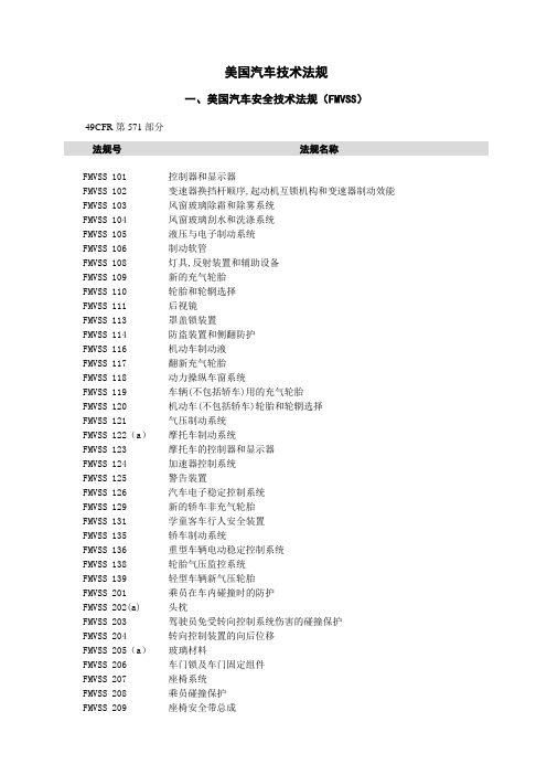
美国汽车技术法规一、美国汽车安全技术法规(FMVSS)49CFR第571部分法规号法规名称FMVSS 101 控制器和显示器FMVSS 102 变速器换挡杆顺序,起动机互锁机构和变速器制动效能FMVSS 103 风窗玻璃除霜和除雾系统FMVSS 104 风窗玻璃刮水和洗涤系统FMVSS 105 液压与电子制动系统FMVSS 106 制动软管FMVSS 108 灯具,反射装置和辅助设备FMVSS 109 新的充气轮胎FMVSS 110 轮胎和轮辋选择FMVSS 111 后视镜FMVSS 113 罩盖锁装置FMVSS 114 防盗装置和侧翻防护FMVSS 116 机动车制动液FMVSS 117 翻新充气轮胎FMVSS 118 动力操纵车窗系统FMVSS 119 车辆(不包括轿车)用的充气轮胎FMVSS 120 机动车(不包括轿车)轮胎和轮辋选择FMVSS 121 气压制动系统FMVSS 122(a)摩托车制动系统FMVSS 123 摩托车的控制器和显示器FMVSS 124 加速器控制系统FMVSS 125 警告装置FMVSS 126 汽车电子稳定控制系统FMVSS 129 新的轿车非充气轮胎FMVSS 131 学童客车行人安全装置FMVSS 135 轿车制动系统FMVSS 136 重型车辆电动稳定控制系统FMVSS 138 轮胎气压监控系统FMVSS 139 轻型车辆新气压轮胎FMVSS 201 乘员在车内碰撞时的防护FMVSS 202(a) 头枕FMVSS 203 驾驶员免受转向控制系统伤害的碰撞保护FMVSS 204 转向控制装置的向后位移FMVSS 205(a)玻璃材料FMVSS 206 车门锁及车门固定组件FMVSS 207 座椅系统FMVSS 208 乘员碰撞保护FMVSS 209 座椅安全带总成法规号法规名称FMVSS 210 座椅安全带总成固定点FMVSS 212 风窗玻璃的安装FMVSS 213 儿童约束系统FMVSS 214 侧碰撞保护FMVSS 216(a) 轿车车顶抗压强度FMVSS 217 客车紧急出口及车窗的固定与松放FMVSS 218 摩托车头盔FMVSS 219 风窗玻璃区的干扰FMVSS 220 学童客车倾翻的防护FMVSS 221 学童客车的车身联结强度FMVSS 222 学童客车乘员座椅和碰撞保护FMVSS 223 后碰撞保护FMVSS 224 后碰撞保护FMVSS 225 儿童约束系统固定点FMVSS 226 降低弹出危险性FMVSS 301 燃料系统的完整性FMVSS 302 汽车内饰材料的燃烧特性FMVSS 303 压缩天燃气车辆燃料系统的完整性FMVSS 304 压缩天燃气燃料箱的完整性FMVSS 305 电动车辆—电解液溅出及电击保护FMVSS 401 乘用车行李厢内部开启机构FMVSS 403 机动车辆地板举升系统FMVSS 404 机动车辆地板举升器的安装FMVSS 500 低速车辆(车速介于20mph-35mph的四轮车辆)二、与FMVSS配套的管理性汽车技术法规法规号法规名称CFR第49篇第510部分信息收集权CFR第49篇第523部分车辆分类CFR第49篇第529部分多阶段车辆的制造CFR第49篇第551部分程序规则CFR第49篇第552部分申请制定有关法规,申请发布缺陷与不符命令CFR第49篇第553部分法规制定程序CFR第49篇第555部分对FMVSS的暂时豁免CFR第49篇第563部分事故数据记录仪CFR第49篇第564部分可更换光源的信息CFR第49篇第565部分车辆识别代号(VIN)--内容要求CFR第49篇第566部分制造商识别CFR第49篇第567部分认证CFR第49篇第568部分2阶段或多阶段制造的车辆CFR第49篇第569部分重新刻槽轮胎法规号法规名称CFR第49篇第572部分假人试验装置CFR第49篇第574部分轮胎的识别和记录保持CFR第49篇第575部分消费者信息法规CFR第49篇第576部分记录的保持CFR第49篇第578部分民事与刑事处罚CFR第49篇第580部分里程表披露要求CFR第49篇第581部分保险杠标准CFR第49篇第583部分零部件的国产化率标识CFR第49篇第585部分分阶段引入报告要求CFR第49篇第587部分可变型壁障CFR第49篇第588部分儿童约束系统的记录保持要求CFR第49篇第591部分联邦安全、保险杠、防盗标准相关的车辆信息CFR第49篇第592部分最初不符合联邦机动车辆安全标准的车辆的注册进口商CFR第49篇第593部分对最初不符合联邦机动车辆安全标准的车辆适合进口的确定CFR第49篇第594部分相关费用规定CFR第49篇第595部分与FMVSS符合性的失效和豁免三、FMVSS的具体实施与汽车产品安全召回法规法规号法规名称CFR第49篇第554部分安全法规实施和缺陷调查CFR第49篇第556部分轻微缺陷与不符的豁免CFR第49篇第557部分申请召开缺陷通知与纠正的听证会CFR第49篇第573部分缺陷与不符的报告CFR第49篇第577部分缺陷与不符的通知CFR第49篇第579部分缺陷与不符的责任四、美国汽车环保技术法规40CFR第86部分法规号法规名称A分部1977年及以后年型的新轻型车辆、新轻型载货车、新重型发动机和1985年及以后年型的以汽油、天然气、液化石油气、和酒精为燃料的新重型车辆的排放法规B分部1977年及以后年型的新轻型车辆、新轻型载货车和新奥托循环完整重型车辆排放试验规程C分部1994年及以后年型新的轻型车辆、轻型载货车和新中型乘用车低温试验规程D分部新汽油、柴油重型发动机排气排放试验规程E分部1978年及以后年型的新摩托车排放法规F分部1978年及以后年型的新摩托车排放试验规程G 分部 新轻型车辆、轻型载货车辆和重型车辆选择性实施检查(SEA ) H 分部 1994年及以后年型轻型车辆和轻型载货车的在用车排放法规 I 分部 新重型柴油机烟度排放试验规程 J 分部 机动车辆及发动机符合性计划费用K 分部 新重型发动机、重型车辆、轻型载货车选择性实施检查(SEA ) L 分部 汽油、柴油重型发动机及重型车(包括轻型载货车)不一致的处罚M 分部 以汽油、天然气、液化石油气、和酒精为燃料的新重型车辆的蒸发排放物试验规程 N 分部 新奥托循环发动机、重型柴油机排气排放物法规,气体和微粒排放物试验规程 O 分部 以汽油为燃料的新奥托循环轻型车辆、轻型载货车的排放法规,认证简化试验规程 P 分部奥托循环重型发动机;以天然气、液化石油气、和酒精为燃料的狄塞尔循环新重型发动机;新奥托循环轻型载货车;以天然气、液化石油气、和酒精为燃料的狄塞尔循环新轻型载货车排放法规,怠速试验规程Q 分部 新的及在用机动车和发动机海拔高度性能调整法规R 分部 针对轻型车辆和轻型载货车的国家志愿性低排放车辆计划的一般规定S 分部 在控制新的和在用的轻型车辆、轻型载货车、完整的奥托循环重型车辆的空气污染方面的一般符合性规定T 分部 制造厂运行的重型柴油机在用试验规程五、美国汽车排放控制方面的管理性法规CFR 第40篇第85部分 法规号 法规名称A 分部---E 分部 备用F 分部豁免清洁可替代燃料转换系统,使其可不满足禁止改动的要求 G 分部---N 分部 备用O 分部 城市大客车改装要求 P 分部 机动车辆和发动机的进口 Q 分部 备用R 分部 对机动车辆和发动机的豁免 S 分部 召回法规T 分部 排放缺陷报告要求 U 分部 备用V 分部排放控制系统的性能保证法规和市场配件的自愿性认证计划法规号法规名称CFR 第40篇第1039部分 新的和在用非道路压燃式发动机排放的控制 CFR 第40篇第1065部分 发动机试验规程CFR 第40篇第1068部分 针对公路、静态源和非道路规划的通用符合性规定 CFR 第40篇第1036部分 新的和在用重型公路发动机排放的控制 CFR 第40篇第1037部分 新重型机动车辆排放的控制 CFR 第40篇第1066部分车辆试验规程W分部排放控制系统的性能保证简易试验X分部《清洁空气法》第二篇A部分第177章中的机动车辆和机动车辆用发动机年型的确定Y分部机动车辆及其发动机符合性规划的费用六、美国汽车噪声技术法规CFR第40篇第205部分法规号项目名称A分部一般性规定B分部中型及重型载货车C分部备用D分部摩托车E分部摩托车排气系统七、美国汽车节能技术法规法规号法规名称CFR第49篇第523部分车辆分类CFR第49篇第525部分豁免满足平均燃油经济性标准CFR第49篇第526部分放宽执行美国1980年汽车燃油节约法的申请和计划CFR第49篇第529部分多阶段汽车制造商CFR第49篇第531部分乘用车(passenger automobile)平均燃油经济性标准CFR第49篇第533部分轻型载货车燃油经济性标准CFR第49篇第534部分在法人关系改变方面制造厂的权利和责任CFR第49篇第535部分中重型车辆燃油经济性规程CFR第49篇第536部分燃料经济性分值的转让和交易CFR第49篇第537部分汽车燃油经济性的报告CFR第49篇第538部分替代燃料车辆的生产鼓励措施CFR第40篇第600部分A分部1977年及以后年型汽车的燃料经济性法规—一般规定CFR第40篇第600部分B分部1978年及以后年型汽车的燃料经济性法规—试验规程CFR第40篇第600部分C分部1977年及以后年型汽车的燃料经济性法规—计算燃料经济性值的规程CFR第40篇第600部分D分部1977年及以后年型汽车的燃料经济性法规—标识CFR第40篇第600部分E分部1977年及以后年型汽车的燃料经济性法规—销售商对燃料经济性信息的获取CFR第40篇第600部分F分部1978年年型的乘用车、1979年年型及以后年型的汽车(轻型载货车和乘用车)的燃料经济性法规—确定制造商平均燃料经济性的规程八、美国汽车防盗技术法规法规号项目名称CFR第49篇第542部分选择应满足防盗标准的系列车型的规程CFR第49篇第541部分联邦机动车辆防盗标准CFR第49篇第543部分对车辆防盗标准的豁免CFR第49篇第545部分联邦机动车辆防盗标准阶段引入和小批量车型报告要求。
fmvss.207中文版

§ 571.207 第207号;标准座椅系统S1. 目的和范围。
本标准为座椅、座椅附件及其安装提出要求,以最大限度地减少因汽车碰撞力导致失效的可能性。
S2. 应用。
本标准适用于客车、多用途客车、卡车和公共汽车。
S3.定义座椅指的是至少拥有一个指定位置的座位。
座椅调节器指的是可对座椅及其背部进行前后调节和旋转的座椅部分,包括固定部分如导轨。
如座椅配有不同级别调节器,那么座椅调节器则是指最高级别的调节器。
S4. 要求。
S4.1 驾驶员座椅。
每辆车都必须拥有一个驾驶员座椅。
S.4.2 普通性能要求。
按照S5的要求测试,除侧向安置座椅和公共汽车乘客座椅外,每个座椅都必须承受如下冲力:(以牛顿计算)(a) 在可调整的任何位置,必须承受座椅质量20倍再乘以9.8的水平向前冲力。
(b) 在可调整的任何位置,必须承受座椅质量20倍再乘以9.8的水平向后冲力。
(c) 如座椅有安全带装置及§ 571.210 S4.2所述的承载物,那么前向座椅的承受力为(a)加上安全带对座椅产生的拉力,后向座椅的承受力为(b)加上安全带对座椅产生的拉力。
(d) 在最后位置,向前向座椅椅背上方横梁或椅背上方施加375牛·米的后向纵力,或向后向座椅后上横梁或椅背施加375牛·米的前向纵力。
S4.2.1 座椅调节器。
按照S5 的测试程序进行测试时,卡车和公共汽车上的座椅除了可以悬浮式垂直升降外,每个座椅必须保持在调整过的位置上。
S4.3. 铰链椅、折叠椅和椅背的保护装置。
除公共汽车乘客座椅和专为舒适而设计的可调椅背式座椅外,铰链椅、折叠椅和椅背必须符合下列条件:(a) 安装有自动上锁装置;(b) 如果座椅背后或旁边拥有其它指定的座椅位置或辅助的座椅位置,必须安装解除这些保护装置的控制系统。
S4.3.1简易解除控制系统。
如果座椅装有保护装置,且后面拥有一个指定的座位位置,那么就必须在座椅上安装上一个简易的解除控制系统;如果需要避免下车麻烦,那么就必须在座椅后的指定座位位置上安装上这个解除控制系统。
FMVSS209中文版
皮带是指窄条非织材料,取代织带用于座椅安全带装置上。 1 型座椅安全带装置是用于骨盆保护装置的一种安全腰带。 2 型座椅安全带装置是骨盆保护装置和上部躯体保护装置的结合。 2a 型肩带是只用于连接与 2 型座椅安全带装置的安全腰带一样的一种上部躯体保护装 置。 上部躯体保护装置是指座椅安全带装置的一部分,用于限制胸部和肩部的移动。 织带指带有连续纬线和加工好布边的窄条平织布。 S4. 要求。 S4.1 (a) 单独使用。一个座椅安全带装置设计每次仅供一个人使用。 (b) 保留 (c) 上部躯体保护装置。2 型座椅安全带装置提供上部躯体保护装置,无需将骨盆保护 装置移动到腹部。上部躯体保护装置用来使在肩部和脊柱上的垂直力减到最小。用于上部躯 体保护装置的硬件位于座椅安全带装置上,因而使乘客受伤的可能性减到最少。 一条 2a 型的肩带应该遵循从 S4.1 到 S4.4(包含 S4.1 和 S4.4 在内)的 2 型座椅安全带 装置的适用要求。 (d) 硬件。正常使用时乘客、衣服或织带所接触的所有硬件零件都应该没有毛刺和锐边。 (e) 释放。1 型或 2 型座椅安全带装置应该装备有容易接近乘客的一个或多个安全带扣,使 乘客能够轻松和迅速地从座椅安全带装置移开。安全带扣释放机械装置应用来将意外脱开的 可能性减到最少。在锁定位置带有释放机械装置的安全带扣应该只有舌片可插入安全带扣末 端的一个开口,此开口用来接收和锁住舌片。 (f) 联接硬件。根据 1973 年 11 月发行的《汽车安全带安装》,美国汽车工程学会推荐准 则 J800c,座椅安全带装置应包括安装汽车必需的所有硬件。然而,座椅安全带装置用于安 装在装备有座椅安全带装置固定器的汽车上,不需要固定器螺母、金属板或垫圈类硬件,但 应有 7⁄16–20 UNF–2A 或 1⁄2–13UNC–2A 的联接螺栓或等效公制硬件。这种硬件应该设计用 来防止使用中联接螺栓和其他零件与汽车脱离。安装的加强板或垫圈用于通用地板,装置应 是钢的,在接近汽车的外围边缘无毛刺和锐边,厚度至少是 1.5 mm,突出区域至少是 2580 mm2。金属板的任何边缘和螺栓孔边缘之间的距离应该至少为 15 mm。任何角都应成至少 6 mm 半径的圆形,因此棱角不少于 135°,边的长度不少于 6 mm。 (g) 调节:(1) 1 型或 2 型的座椅安全带装置应该都能够进行调节,使尺寸和重量适合从 5%成年妇女到 95%成年男子范围的乘客。座椅安全带装置应在乘客伸手可及的地方,或者 有一个自动锁紧式牵引器、紧急锁紧式回卷器或者调节装置。 (2) 当在有可调座位的汽车上使用时,不管座位位置如何,1 型或 2 型的座椅安全带装 置应该符合 S4.1(g)(1)的要求。然而,如果座位的靠背是分别调整的,那么 S4.1(g)(1)的要求 只需满足在制造商名义设计安放位置上的座椅靠背。 (3) 在 S4.1(g)(1)所提到的成人乘客应该有以下尺寸:
美国联邦机动车安全标准FMVSS

FMVSS204
转向控制装置的向后位移
34
FMVSS205
玻璃材料
35
FMVSS206
车门锁及车门固定组件
36
FMVSS207
座椅系统
37
FMVSS208
乘员碰撞保护
38
FMVSS209
座椅安全带总成
39
FMVSS210
座椅安全带总成固定点
40
FMVSS211
车轮螺母、轮辐和轮彀盖
41
FMVSS212
62
86-A
1977及其后型号年的轻型车辆,轻型货车,重型柴油车排污法规一般规定
63
86-E
1978及其后型号年新摩托车排气污染法规的一般规定
64
86-F
1987及其后型号年新摩托车排气污染规程试验规程
65
205
交通噪声污染的控制设备
66
205-B
中型和重型载货汽车
67
205-E
摩托车排气系统
68
325
符合洲际机动运输车辆噪声辐射标准
69
325-A
一般规定
70
325-B
管理规定
71
325-C
测试设备
72
325-D
噪声辐射测量公路运行
73
325-E
噪声辐射测量停车试验
74
325-F
修正值
75
325-G
排气系统和轮胎
照明装置、反射器和电器设备
53
393-C
制动
54
393-D
窗用玻璃与车窗结构
55
393-E
燃料系统
56
393-F
美国汽车安全技术法规(FMVSS)中文版

101-控制器和显示器摘要-本标准要求基本控制器位于当驾驶员被腰带限制以及躯干上部也被限制的情况下能够触手可及的地方。
同时要求确定的安装在仪表盘的控制程序能够被识别。
要求-必须确定所有手动操作控制都要用文字标识。
除脚踏式控制或安装在转向柱上的手动操作控制器之外,无论何时前照灯打开时,基本的控制识别和显示系统必须被照亮。
必须确定某些必要的手工操作控制器和某些显示系统都要有一个标识显现出来,而且这些标识能够被照亮。
每辆乘用车,多用途乘用车,卡车和公共汽车所装的控制器,指示器或指示灯栏在表1或表2(PDF格式),必须符合本标准要求的位置,标识,颜色,和照明的要求。
指示器照明亮度(a)指必需为指示器提供照明,足以使驾驶员在夜间和白天行驶的状况下可以看到他们。
(b)提供所需可视的同时,设备应该可以手动或自动的进行调节,除了制动器,大灯,转向灯,安全带的指示器和识别装置在任何驾驶条件下不应调节到不可视的情况,室内灯的亮度(一)任何内源照(1)光照强度,手动或自动调节,提供至少两个级别的亮度;(2)其中之一是很弱的光线强度,对已经适应黑暗环境道路状况的驾驶员可辨别;(3)作为一种手段关闭。
颜色-表1(PDF格式)中所示的每个指示装置的灯光必须是独特的,在该表中的第6栏已给出。
没有在表中1中(PDF格式)的任何指标灯或指示器的标识的灯光颜色不能影响到驾驶员辨别。
102-变速器换挡杆顺序摘要:该标准特别强调变速器换挡顺序,起动机的互锁机构和变速器,以减少换挡错误的可能性。
在变数器档位在驱动挡位置时启动,并能提供在速度低于40公里/小时(25英里)的辅助制动。
乘用车变速器换挡位置的布置:空挡位置应该在前进和倒挡中间。
105-液压和电动制动系统摘要:本标准规定车辆配备液压和电动制动系统以及相关的停车制动系统,以确保在正常条件下和紧急情况下能够安全制动。
要求:制动距离。
(a)制动器应该能够使额定车辆总重不超过8000磅的车辆安全的停车。
汽车碰撞安全法规大全(中文版)
汽车碰撞安全法规大全〔中文版〕中国篇乘用车正面碰撞的乘员保护〔GB 11551-2003〕汽车侧面碰撞的乘员保护〔GB 20071-2006〕乘用车后碰撞燃油系统安全要求〔GB 20072-2006〕防止汽车转向机构对驾驶员伤害的规定〔GB 11557-1998〕汽车座椅、座椅固定装置及头枕强度要求和试验方法〔GB15083-2006〕汽车安全带固定点〔GB 14167-2006〕汽车前、后端保护装置〔GB 17354-1998〕C-NCAP 前部正面刚性壁障碰撞试验方法C-NCAP 前部偏置碰撞试验方法C-NCAP 侧面碰撞试验方法C-NCAP 评分方法欧洲篇防止汽车碰撞时转向机构对驾驶员伤害认证的统一规定〔ECE R12〕关于汽车安全带安装固定点认证的统一规定〔ECE R14〕关于车辆座椅、座椅固定装置及头枕认证的统一规定〔ECE R17〕关于车辆内部安装件认证的统一规定〔ECE R21〕关于后面碰撞汽车结构特性认证的统一规定〔ECE R32〕关于正面碰撞汽车结构特性认证的统一规定〔ECE R33〕关于车辆火险预防措施认证的统一规定〔ECE R34〕关于汽车前后端保护装置〔保险杠等〕认证的统一规定〔ECE R42〕关于车辆正面碰撞乘员保护认证的统一规定〔ECE R94〕关于车辆侧面碰撞乘员保护认证的统一规定〔ECE R95〕EuroNCAP 前部碰撞试验方法EuroNCAP 侧面碰撞试验方法EuroNCAP 侧面撞柱评估标准EuroNCAP 车辆对乘员颈部保护的动态评估试验方法EuroNCAP 行人保护试验方法EuroNCAP 儿童保护评估方法EuroNCAP 评估方法与生物力学极限GTR 行人保护法规EC 行人保护法规北美篇内饰件碰撞特性要求及试验方法〔FMVSS 201〕头枕的碰撞保护〔FMVSS 202a〕转向机构对驾驶员的碰撞保护〔FMVSS 203〕对方向盘后移量的要求〔FMVSS 204〕座椅系统〔FMVSS 207〕乘员碰撞保护〔FMVSS 208〕乘员离位〔OOP〕保护〔FMVSS 208〕儿童约束系统要求〔FMVSS 208〕安全带安装固定点认证的统一规定〔FMVSS 210〕儿童约束系统〔FMVSS 213〕侧面碰撞保护〔FMVSS 214〕保险杠标准〔CMVSS 215〕车顶抗压〔FMVSS 216〕儿童约束安装点系统〔FMVSS 225〕燃油系统完整性〔FMVSS 301〕电动车辆的电解液溢出和电击保护〔FMVSS 305〕保险杠标准〔PART 581〕US NCAP 前部碰撞试验方法US NCAP 侧面碰撞试验方法US NCAP 翻滚试验方法US NCAP 评分方法IIHS 前部碰撞试验方法IIHS 侧面碰撞试验方法IIHS 低速碰撞试验方法附录EuroNCAP 新评估方法建议稿假人伤害指标描述。
FMVSS_208_乘员碰撞保护(中文版)
(c) 当在速度不小于 30 英里/小时(48km/h)纵向行驶的过程中与一个固定壁障垂直碰 撞时,在 S8.1 的测试条件下,对每一个前排外侧位置的由类型 2 安全带总成约束的假人进 行检查,座椅安全带总成或固定装置的承载单元并没有完全分离。
满足 S4.1.2.1,S4.1.2.2 和 S4.1.2.3 的要求,如果汽车制造商认为,在进行相应的考虑时, 不需要确认某车辆不符合本标准的要求,则不应该被认为不符合本标准。
中 S4.1.3.3.2 在满足 S4.1.3.4 和 S4.1.5 的条件下,按照 S4.1.3.3.1,符合 S4.1.2.1 规定的乘用车
(b) 在任何中心前部指定座椅位置,装有满足第 209 号标准和 S7.1、S7.2 标准要求 的类型 1 或类型 2 安全带,和满足 S7.3 标准要求的座椅安全带预警装置;
(c) 在每一个其它指定的座椅位置,有一个装有满足标准 209 和 S7.1、S7.2 标准要 求的类型 1 或类型 2 安全带总成。
S4.1.1.3 第三选择——配有安全带预警装置的腰部和肩部安全带。
1
S4.1.1.3.1 除了活动顶棚和敞篷轿车外,汽车应: (a) 在每一个前排外侧指定的座椅位置装有满足§571.209 标准及本标准 S7.1 和 S7.2
要求的类型 2 安全带总成,该总成包括一个整体式的或可分离上部躯干式的安全带,并装有 按照 S7.3 的要求的安全带预警系统;
联邦机动车安全标准
FMVSS 208 乘员碰撞保护
S1 范围
这个标准指定了碰撞中,汽车乘员保护的性能要求。
FMVSS302中文版标准
FMVSS302中文版FMVSS302中文版:汽车内饰材料的燃烧特性§ 571.302 第302号标准; 内部材料的燃烧性能。
S1.范围。
本标准说明了对汽车乘客车厢使用材料的阻燃性的要求。
S2.目的。
本标准旨在减少车辆发生火灾时所造成的伤亡,尤其是那些起源于车厢内部如火柴或香烟引起的火灾。
S3. 适用。
本标准适用于客车、多用途客车、卡车以及公共汽车。
S3A. 定义。
乘客车厢空气间层是指乘客车厢内通常包含可更新空气的空间。
S4. 要求.S4.1 S4.2中描述的乘客车厢中所包含的成分需符合S4.3中的要求:座垫、座椅靠背、座椅安全带、车顶衬里、可折叠车顶、扶手、所有装饰面板(包括车门、前、后、侧面面板)、车厢货架、头枕、地板覆盖物、遮阳板、窗帘、遮光罩、轮罩、发动机舱盖、垫套以及其它内部材料,包括那些用来吸收碰撞事故中产生震荡和碰撞能量的元件。
S4.1.1 [保留]S4.2乘客车厢空气间层中如果某单一或复合材料的任一部分是在13 mm以内,应满足S4.3中的要求。
S4.2.1 如果某种材料在每一个接触点都不黏附其他材料,单独测试时应该符合S4.3中的要求。
S4.2.2 如果某种材料在每一个接触点都黏附其他材料,在测试中应该按S4.3中的要求作为其他材料的复合物来测试。
深度乘客车厢空气间层单独测试的材料作为复合物测试的材料黏结界面剪切处无黏结界面毫米(mm)乘客车厢空气间层所有尺寸单位均为毫米(mm)材料A与材料B没有黏附界面,故单独测试。
材料B的部分在乘客车厢空气间层小于13 mm,材料B和C在每个点都黏附,因此,B和C就作为一个复合材料来测试。
在C上的剪切如图所示,使试样为13 mm厚。
S4.3(a) 按照S5进行测试时,S4.1和S4.2中描述的材料不应该被燃烧或在其表面传递超过102 mm/min的火焰锋。
传递火焰锋的要求不能在依照S5的测试要求所剪的试样上应用。
(b) 如果材料在从开始计时燃烧到停止燃烧不超过60秒的时间,并且燃烧的长度从计时点到停止点不超过51 mm则被认为符合S4.3(a)燃烧率的要求。
FMVSS125报警装置中文版

镑的货车携带的装置。该装置用于警告向停驻车辆靠近的行人或车辆。用于永久
性安装于车辆上的装置除外。
S 4 定义
进入角 指的是通过被测物体中心和表面法线的直线和通过被测物体中心和光源
中心的直线所形成的角度
荧光 指的是由于吸收可见光谱外的更短波光线而具有的发散可见光的属性
观察角 指的是由从观察点到被测物体中心的线和从被测物体中心到光源中心的
(a) 围在不透明的保护性重复使用容器中,2 或 3 个警告装置一起销售在一辆
车上作为一组来用、可以装在一个容器中的除外;或者
(b) 通过新机动车任何不透光的、密封的并易到达车厢的安全附件,该附件有
车辆生产厂家随车辆一起提供。
S 5.1.3 警告装置的设计应当能够使其不需使用工具就可以在其容器内竖起和
(e) 在每一个入射角和观察角,计算出红色反光材料的入射脚蜡烛的总烛光
S 6.3 亮度测试 按照如下步骤测试橙色荧光材料的亮度:
(a) 除非使用两用材料,应当阻止红色反光材料影响橙色荧光材料亮度的光
度测量
(b) 使用 150 瓦高压氙紧密弧光灯作为光源,从 45 度入射角和 90 度观察角
照亮角形底部的低边水平并位于地面以上 1 英寸以上。
(b) 除部分材料必须用来提供紧固、旋转珠和其他办法来支撑警告装置外,
必需的反射材料和荧光材料任何部分都不应当被警告装置的其他部分弄模糊。在
任何情况下,都要在三角形上使用足够的反光和荧光材料,以满足 S5.4 和 S.5
的要求。
S 5.2.2 警告装置的三角形部分每条边都应当不小于 17 且不大于 22 英寸,不小
于 2 不大于 3 英寸宽。(如图表 1)
S 5.2.3 警告装置三角形部分每一面都应当有统一宽度(不少于 0.75 不多于
- 1、下载文档前请自行甄别文档内容的完整性,平台不提供额外的编辑、内容补充、找答案等附加服务。
- 2、"仅部分预览"的文档,不可在线预览部分如存在完整性等问题,可反馈申请退款(可完整预览的文档不适用该条件!)。
- 3、如文档侵犯您的权益,请联系客服反馈,我们会尽快为您处理(人工客服工作时间:9:00-18:30)。
(坐着).腰围 . 599 mm 1080 mm.
(坐着).胸厚 . 190 mm 267 mm.
胸围:
乳头............. 775 mm 1130 mm.
上部............. 757 mm 1130 mm.
下部............. 67ห้องสมุดไป่ตู้ mm 1130 mm.
(h) 织带。座椅安全带装置上的织带末端应该是密闭或处理过的以防止散纱。座椅安全
1
皮带是指窄条非织材料,取代织带用于座椅安全带装置上。 1 型座椅安全带装置是用于骨盆保护装置的一种安全腰带。 2 型座椅安全带装置是骨盆保护装置和上部躯体保护装置的结合。 2a 型肩带是只用于连接与 2 型座椅安全带装置的安全腰带一样的一种上部躯体保护装 置。 上部躯体保护装置是指座椅安全带装置的一部分,用于限制胸部和肩部的移动。 织带指带有连续纬线和加工好布边的窄条平织布。 S4. 要求。 S4.1 (a) 单独使用。一个座椅安全带装置设计每次仅供一个人使用。 (b) 保留 (c) 上部躯体保护装置。2 型座椅安全带装置提供上部躯体保护装置,无需将骨盆保护 装置移动到腹部。上部躯体保护装置用来使在肩部和脊柱上的垂直力减到最小。用于上部躯 体保护装置的硬件位于座椅安全带装置上,因而使乘客受伤的可能性减到最少。 一条 2a 型的肩带应该遵循从 S4.1 到 S4.4(包含 S4.1 和 S4.4 在内)的 2 型座椅安全带 装置的适用要求。 (d) 硬件。正常使用时乘客、衣服或织带所接触的所有硬件零件都应该没有毛刺和锐边。 (e) 释放。1 型或 2 型座椅安全带装置应该装备有容易接近乘客的一个或多个安全带扣,使 乘客能够轻松和迅速地从座椅安全带装置移开。安全带扣释放机械装置应用来将意外脱开的 可能性减到最少。在锁定位置带有释放机械装置的安全带扣应该只有舌片可插入安全带扣末 端的一个开口,此开口用来接收和锁住舌片。 (f) 联接硬件。根据 1973 年 11 月发行的《汽车安全带安装》,美国汽车工程学会推荐准 则 J800c,座椅安全带装置应包括安装汽车必需的所有硬件。然而,座椅安全带装置用于安 装在装备有座椅安全带装置固定器的汽车上,不需要固定器螺母、金属板或垫圈类硬件,但 应有 7⁄16–20 UNF–2A 或 1⁄2–13UNC–2A 的联接螺栓或等效公制硬件。这种硬件应该设计用 来防止使用中联接螺栓和其他零件与汽车脱离。安装的加强板或垫圈用于通用地板,装置应 是钢的,在接近汽车的外围边缘无毛刺和锐边,厚度至少是 1.5 mm,突出区域至少是 2580 mm2。金属板的任何边缘和螺栓孔边缘之间的距离应该至少为 15 mm。任何角都应成至少 6 mm 半径的圆形,因此棱角不少于 135°,边的长度不少于 6 mm。 (g) 调节:(1) 1 型或 2 型的座椅安全带装置应该都能够进行调节,使尺寸和重量适合从 5%成年妇女到 95%成年男子范围的乘客。座椅安全带装置应在乘客伸手可及的地方,或者 有一个自动锁紧式牵引器、紧急锁紧式回卷器或者调节装置。 (2) 当在有可调座位的汽车上使用时,不管座位位置如何,1 型或 2 型的座椅安全带装 置应该符合 S4.1(g)(1)的要求。然而,如果座位的靠背是分别调整的,那么 S4.1(g)(1)的要求 只需满足在制造商名义设计安放位置上的座椅靠背。 (3) 在 S4.1(g)(1)所提到的成人乘客应该有以下尺寸:
(j) 标记。每个座椅安全带装置均应该永久和清楚地标示制造年度、型号、制造商或经
销商的名称或商标、或进口商(如果为美国以外的国家所制造)。一个型号应该包括有特定
类型纤维织物和结构的织带的单一结合,以及配有特定设计的硬件。相同型号的织带可能有
多种颜色,然而每种颜色的织带都应该遵循 S4.2 的织带规定。 (k) 安装指示。除了由汽车制造商安装在汽车座椅上的安全带装置之外,一个座椅安全
S4.3 硬件的要求。 (a) 耐腐蚀性。 (1) 在受到 S5.2(a)中所说明的影响后,除了地板下加强板和垫圈外周
边缘或孔边缘的容许铁腐蚀之外,座椅安全带装置联接硬件的重要表面应该是无铁腐蚀的。 一种可能的选择是,根据铜+镍+铬及镍+铬的电解沉积镀层,根据美国测试和材料协会标准 B456–79,在地板上或靠近地板的硬件应该至少有一层镍电镀层,或至少 SC2 运行条件数目 的铜和镍保护免受腐蚀,或其他联接硬件应该涂有一层镍电镀层,或 SC1 运行条件数目的 铜和镍保护,但是这类硬件不应该在受到最大压力的位置进行挂镀。
(c) 联接硬件。(1) 当运用 S5.2(c)(1)所说明的步骤进行测试时,吊环螺栓、台阶螺栓或 其他用于将座椅安全带装置的骨盆保护装置固定在汽车上的螺栓应该承受 40,034N 的力,除 了用来安装汽车指定型号的座椅安全带装置的联接硬件(两个或更多座椅安全带装置的末端 不能通过一个单螺栓连接汽车)之外,这类联接硬件应该有至少 22,241 N 断裂强度。
(2) 座椅安全带装置的安全带扣、回卷器和金属零件的表面,除了联接硬件之外,在受 到 S5.2(a)所说明的影响之后,当佩带座椅安全带装置或者直接通过织带移动到乘客时,应 该是没有铁腐蚀或非铁腐蚀的。
(b) 耐热性。当座椅安全带装置的塑料或其他非金属硬件零件受到 S5.2(b)所说明的条 件影响时,不应该弯曲或损坏,从而导致此装置运转不正常或不能遵守此部分和 S4.4 的适 用要求。
(3) 在 S5.2(d)(3)中规定的 1779 N 压缩力下,1 型或 2 型座椅安全带装置的安全带扣不能 释放。在压缩力取消后,安全带扣应可操作且满足 S4.4 的适用要求。
联接硬件指设计用来将座椅安全带装置的织带固定在汽车上的任何或全部硬件。 自动锁定回卷器是指一个回卷器结合调节硬件,通过一个正自动锁定装置,在锁定时所 承受的约束力。 安全带扣是指将乘客固定在座椅安全带装置上的快速释放连接器。 紧急锁定回卷器指的是安装有调节硬件的回卷器,锁定装置在紧急状况时通过汽车加 速,使椅套相对于汽车运动启动或者其他的自动动作启动并且在锁定时能够经受约束力。 硬件是指座椅安全带装置的任何金属或者硬质塑料部分。 负载限制器是指控制座椅安全带上张力的一个座椅安全带装置构件或零件,在碰撞时用 于调节受座椅安全带装置保护乘客被施与的力。 非锁定回卷器是指通过施加一个小的外力,使回卷器的织带延伸到最长,即装置长度不 能进行调整且也许织带在延伸到最大限度时可能或不能承受约束力。 骨盆保护装置是指座椅安全带装置或其中一部分用于限制骨盆的移动。 回卷器是指在座椅安全带装置上,存储织带的一部分或全部的装置。 座椅靠背固定器是指一些座椅安全带装置的部分,设计用来限制座椅靠背的前向运动。 座椅安全带装置是指任何皮带、织带或相似装置,是设计用来减轻发生事故的而把一个 人固定在汽车上,包括设计用来把座椅安全带装置安装在汽车上所有必需的安全带扣、其他 扣件以及所有硬件。
部分以及在制造商指定设计安放位置上的座椅靠背以外,座椅安全带的织带宽度应该不少于
46mm。
(b) 断裂强度。当使用 S5.1(b) 中详细说明的步骤测试时,座椅安全带装置的织带应
有至少以下的断裂强度:1 型座椅安全带装置—26,689 N;2 型座椅安全带装置—
3
22,241 N 用于骨盆保护装置;17,793 N 用于上部躯体保护装置。 (c) 延长。除了 S4.5 规定的之外,根据 S5.1(c) 中规定所受的指定力时,座椅安全带装
带装置应该附有说明卡,此说明卡提供将安全带安装在汽车上的充分信息。
安装指示应该说明此座椅安全带装置是否是通用安装或只是特别规定汽车的安装,并且应
该至少包括 1973 年 11 月发行的《汽车安全带安装》,美国汽车工程学会推荐准则 J800c 中
的条款。如果此座椅安全带装置仅仅用于特别规定的汽车,那么座椅安全带装置应该或是永
带装置上的织带末端有一个金属对金属的安全带扣,是乘客用来调整座椅安全带装置的尺
寸,而不是拉出最大尺寸调节的调节硬件。为织带在座椅靠背和座垫之间基本上无阻碍移动
作好预备,并附在位于座椅后面的一个回卷器上。
(i) 条带。用于维持约束力的座椅安全带装置的皮带应该遵循 S4.2 的织带规定,如果皮
带是由刚性材料制造,那么应该遵循 S4.2、S4.3 和 S4.4 的适用要求。
2
5%成年妇女
95%成年男 性
重量............. 46.3 千克 97.5 千克
直 立 坐 姿 高 785 mm 965 mm.
度 .......................
臀宽(坐着) .. 325 mm 419 mm.
臀围............. 925 mm 1199 mm.
4
(d) 安全带扣的释放。 (1)当施加至多 133 N 的力时,1 型或 2 型座椅安全带装置的安全 带扣应该释放。
(2) 设计用于安全带扣释放力的按钮应用的安全带扣应有运用释放力的 452mm2 的最小 面积和 10mm 的最小线性尺寸,或用于安全带扣释放力的杠杆运用的安全带扣应沿着安全 带扣释放的启动部分的汽缸全部长度,允许一个汽缸(直径为 10mm 和长度为 38mm)插入 到此汽缸的至少中点。用来释放的安全带扣应该允许两个或更多手指来促使释放。
(e) 耐光性。当暴露在炭精电弧光下并经过 S5.1(e)所详细说明的程序进行测试后,座椅 安全带装置的织带暴露炭精电弧下之前应该有至少 60%的断裂强度且应具有美国纺织品染 化工作者协会(地址:北卡罗来纳州达勒姆,邮箱:886)所出版的至少第二灰度级的色泽 稳定性。
(f) 耐微生物性。在受微生物影响后,根据 S5.1(f) 详细说明的步骤进行测试,座椅安全 带装置的织带在微生物影响前有不少于 85%的断裂强度。
置的织带不应该超过以下延长:1 型座椅安全带装置—在 11,120 N 时 20 %;2 型座椅安全 带装置用于骨盆保护装置的织带在 11,120 N 时为 30%;用于上部躯体保护装置的织带在 11,120 N 时是 40%。