SAE international J1772 Charging Configurations and ratings terminology 10-3-2012
国内外电动汽车充换电设施标准及应用现状(下)

36-CHINA ·January(接上期)⑵SAE充换电标准SAE J1772标准规定了电动汽车和插电式混合动力汽车的传导充电要求,涵盖了对电动汽车和插电式混合动力汽车实现充电的物理、电气、功能和性能一般要求,定义了通用电动汽车和插电式混合动力汽车与供应设备进行导电充电的方法,包括操作要求以及车辆插孔和配对连接器的功能和尺寸要求。
而SAE J1773确立了在相同地理区域内电动汽车感应充电的最低接口兼容性要求。
SAE J2954标准是针对轻型插电式混合动力汽车和电动汽车的无线功率传输和对准方法编制的,该规范定义了互操作性、电磁兼容性、电动场、最低性能、安全性以及对轻型电动和插电式混合动力电动汽车进行无线充电测试的可接受标准,支持家庭(专用)充电和公共无线充电。
SAEJ1772-2017中明确了AC充电和DC充电水平,如表5所示。
◆文/长沙民政职业技术学院电子信息工程学院 张葵葵国内外电动汽车充换电设施标准及应用现状(下)表5 AC和DC充电水平Copyright©博看网 . All Rights Reserved.2021/01·汽车维修与保养37栏目编辑:高中伟 gzw@New Energy Vehicles 新能源汽车⑶中国充换电标准中华人民共和国国家标准GB/T 20234.1,2,3-2011由三部分组成,形式接近于IEC 62196-1,2,3 ,解决了中国国内不同地区,不同电网公司,充电接口不统一的问题。
在中国国家标准 GB/T 20234.3 中定义的直流充电电压和电流分别是 750V和250A ,充电功率可以达到150kW以上,相比目前日本电动汽车快速充电器协会 CHAdeMO标准中60kW 的功率要高出一倍,所以在连接器设计中考虑到电气间隙及爬电距离的影响,结构尺寸有很大的不同,目前主要用于城市纯电动公交大巴的电能补充。
国家电网公司标准(Q/GDW)制定的电动汽车充换电标准也被积极采纳。
SAEJ1772电动车传导式充电介面标准规范介绍

120V AC, 1-Phase AC Level 1 120V AC, 1-Phase
12A 16A
15A (el 2
208 to 240V AC, 1Phase
≦80A
Per NEC 625
Charge Method Electrical Ratings (North America)
J1772 JAN 2010版本主要定義AC Level 1及AC Level 2傳導式充電介面標 準,DC Charging部份的規範還未定義完成,因J1772 Task Force還在持 續討論當中,以目前電動車及相關產業的發展速度來看相信很快就會有新 J1772版本發行,其中會包含DC Charging傳導式充電介面標準訂定及更 進一步相關設備溝通機制。
本文件最主要目的為介紹及解讀saej1772針對電動車充電介面標準規範同時針對evse充電設備charge運作及溝通機制做介紹使得讀者可以清楚了解此規範所訂定的內容
Introduction:
本文件最主要目的為介紹及解讀SAE J1772針對電動車充電介面標準規範, 同時針對EVSE(充電設備),Charge Coupler(充電座)及EV(電動車)之間的 運作及溝通機制做介紹,使得讀者可以清楚了解此規範所訂定的內容。
0
Working on Better Solutions
AC Level1 & AC Level2的定義:
Charge Method
Nominal Supply Voltage (Volt)
Maximum Current (Amps-continuous)
Branch Circuit Breaker rating (Amps)
3. 此PWM的duty cycle是有意義的,其表示EVSE可以提供的最大電流量(計算 方式請參考上一張slide: supply current rating VS pilot circuit duty cycle) 。
非车载传导式充电机与电动汽车之间的数字通信协议
非车载传导式充电机与电动汽车之间的数字通信协议
非车载传导式充电机与电动汽车之间的数字通信协议通常采用以下几种:
1. SAE J1772:这是一种北美标准的数字通信协议,用于交流
充电接口的通信。
它定义了一种基于串行通信的消息传输方式,用于车载充电机与充电桩之间的通信。
2. GB/T 20234.3-2011:这是中国国家标准的数字通信协议,
主要用于交流和直流充电桩之间的通信。
它定义了一种基于串行通信的消息传输方式,支持多种通信协议和数据格式。
3. CHAdeMO:这是一种由日本电动车协会开发的通信协议,
主要用于直流快充充电接口的通信。
它定义了一种基于CAN
总线的消息传输方式,支持车载充电机与充电桩之间的双向通信。
4. CCS:这是一种由欧洲汽车制造商协会和美国汽车制造商协会合作开发的通信协议,主要用于直流快充充电接口的通信。
它基于CAN总线和以太网技术,支持车载充电机与充电桩之
间的双向通信。
这些协议通常规定了通信的消息格式、数据传输速率、错误检测和纠正等方面的规范,以确保充电机与电动汽车之间的可靠通信。
汽车维修手册.pdf_1702090250.0742981说明书

IndexAccessories and Modifications.... 107Accessories................................. 107Additional Safety Precaution.... 108Modifications............................. 108ACCESSORY (Ignition KeyPosition)........................................ 67Accessory Power Socket................ 75AddingAutomatic TransmissionFluid........................................ 153Brake Fluid................................. 155Clutch Fluid................................ 155Engine Coolant........................... 147Engine Oil................................... 143Manual Transmission Fluid..... 154Power Steering Fluid................. 156Windshield Washer Fluid......... 152Additional Information AboutYour Seat Belts........................ 42Lap Belt......................................... 43Lap/Shoulder Belt....................... 42Seat Belt Maintenance................ 44Seat Belt System Components (42)Additional Information AboutYour SRS................................... 45Additional Safety Precautions.... 48How the SRS IndicatorWorks........................................ 47How Your Airbags Work............ 45SRS Components......................... 45Additives, Engine Oil..................... 144AdjustmentsHead Restraints........................... 70Mirrors.......................................... 73Seats.............................................. 69Steering Wheel............................ 65Airbag (SRS)................................ 9, 45Air Cleaner Element...................... 157Air Conditioning System................. 78Maintenance............................... 164Usage............................................. 78Air Outlets (Vents).......................... 80Air Pressure, Tires........................ 166High Speed Driving................... 167Normal Driving.......................... 167Alcohol in Gasoline........................ 220Antifreeze....................................... 147Anti-theft Steering ColumnLock (67)Appearance Care........................... 183Ashtrays (Optional)......................... 75Audio System................................... 86Automatic Transmission............... 118Capacity, Fluid........................... 216Checking Fluid Level................ 153Shifting........................................ 118Shift Position Indicator............. 118Shift Lever Positions................. 119Shift Lock Release (122)BatteryCharging SystemIndicator............................ 55, 202Jump Starting............................. 197Maintenance............................... 160Specifications............................. 217Before Driving................................. 99Belts, Seat..................................... 8, 42Beverage Holder.............................. 74Body Repairs. (188)CONTINUEDIndexBrakesBreak-in, New Linings .............. 100Fluid............................................ 154Light, Burned-out...................... 177Parking.......................................... 73System Indicator.................. 55, 204Wear Indicators......................... 124Braking System.............................. 124Break-in, New Car......................... 100Brightness Control, Instruments... 62Brights, Headlights......................... 61Bulb ReplacementBack-up Lights........................... 177Brake Light................................ 177Front Parking Lights................. 175Front Side Marker Lights......... 175Headlights.................................. 174High-mount Brake Light.......... 178Interior Light.............................. 180License Plate Lights.................. 179Rear Side Marker Lights.......... 177Specifications............................. 217Turn Signal Lights..................... 175Bulbs, Halogen. (174)Cables, Jump Starting With.......... 197Capacities Chart............................. 216Carbon Monoxide Hazard.............. 49Cargo Area Cover............................ 72Carrying Cargo.............................. 109Cassette PlayerCare............................................... 94Operation...................................... 92CAUTION, Explanation of............... ii CD Changer...................................... 95CD Player.......................................... 95Certification Label......................... 214Chains............................................. 171Change OilHow to......................................... 145When to....................................... 134Changing a Flat Tire..................... 191Changing Engine Coolant............. 149Charging System Indicator.... 55, 202CheckingAutomatic TransmissionFluid........................................ 153Battery Condition...................... 160Brake Fluid (155)Clutch Fluid................................ 155Drive Belts.................................. 165Engine Coolant........................... 105Engine Oil................................... 104Fuses.......................................... 205Manual Transmission Fluid..... 154Power Steering Fluid................. 156Checklist, Before Driving............. 114Child Safety...................................... 21Cleaner Element, Air..................... 157CleaningExterior....................................... 184Interior........................................ 186Seat Belts.................................... 186Vinyl............................................ 186Windows..................................... 187Clock, Setting the ............................ 91Clutch Fluid.................................... 155CO in the Exhaust......................... 222Cold Weather, Starting in............. 115Compact Spare............................... 190Consumer Information*................ 226Controls, Instruments and.............. 51CoolantAdding......................................... 147Checking.....................................105IndexProper Solution.......................... 147Replacing.................................... 149Temperature Gauge.................... 58Corrosion Protection..................... 187Crankcase Emissions ControlSystem......................................... 222Customer Relations Office.. (226)DANGER, Explanation of................. ii Dashboard.................................... 2, 52Daytime Running Lights................. 61Dead Battery, What to Do............ 197Defects, Reporting Safety............. 230Defog and Defrost........................... 83Defogger, Rear Window................. 64Defrosting the Windows................. 83DEXRON ® III AutomaticTransmission Fluid.................... 153Dimensions..................................... 216Dimming the Headlights................ 61DipstickAutomatic Transmission........... 153Engine Oil................................... 104Directional Signals (62)Disabled, Towing Your Car If...... 210Disc Brake Wear Indicators......... 124Disposal of Used Oil...................... 146DoorsLocking and Unlocking............... 68DOT Tire Quality Grading........... 218Downshifting, 5-speed ManualTransmission.............................. 116Drive Belts...................................... 165Driver and Passenger Safety............ 5Driving............................................ 113Economy..................................... 106In Bad Weather.......................... 126In Foreign Countries.. (221)Economy, Fuel............................... 106Emergencies on the Road............. 189Battery, Jump Starting.............. 197Brake System Indicator............ 204Changing a Flat Tire................. 191Charging System Indicator...... 202Checking the Fuses................... 206Low Oil Pressure Indicator...... 201Malfunction Indicator Lamp. (203)Overheated Engine................... 199Emergency Brake............................ 73Emergency Flashers....................... 64Emergency Towing....................... 210Emissions Controls........................ 222EngineBelts.............................................165Coolant Temperature Gauge..... 58Malfunction IndicatorLamp................................. 56, 203Oil Pressure Indicator......... 55, 201Oil, What Kind to Use............... 143Overheating................................ 199Specifications............................. 216Engine Speed Limiter .......... 117, 121Ethanolin Gasoline....................... 220Evaporative Emissions Controls.. 222Exhaust Fumes................................ 49Expectant Mothers, Use of SeatBelts by......................................... 19Exterior, Cleaning the. (184)CONTINUEDIndexFabric, Cleaning............................. 186Fan, Interior...................................... 78Features, Comfort andConvenience................................. 72Filling the Fuel Tank..................... 101FilterAir Cleaner................................. 157Oil................................................ 1455-speed Manual TransmissionChecking Fluid Level................ 154Shifting the................................. 116Flashers, Hazard Warning.............. 64Flat Tire, Changing a.................... 191FluidsAutomatic Transmission........... 153Brake........................................... 154Clutch.......................................... 154Manual Transmission............... 154Power Steering........................... 156Windshield Washer................... 152FM Stereo RadioReception...................................... 89Folding Rear Seat............................ 71Foreign Countries, Driving in (221)Four-way Flashers........................... 64Front End, Towing byEmergency Wrecker................. 210Fuel.................................................. 100Fill Door and Cap....................... 101Gauge............................................ 58Octane Requirement................. 100Oxygenated................................ 220Reserve Indicator......................... 56Tank, Filling the......................... 101Fuses, Checking the. (205)Gas Mileage, Improving................ 106Gasohol........................................... 220Gasoline.......................................... 100Fuel Reserve Indicator................ 56Gauge............................................ 58Octane Requirement................. 100Tank, Filling the......................... 101Gas Station Procedures................. 101GaugesEngine CoolantTemperature............................ 58Fuel (58)Gearshift Lever PositionsAutomatic Transmission........... 1185-speed ManualTransmission.......................... 116Glass Cleaning............................... 187Glove Box.. (74)Halogen Headlight Bulbs.............. 174HatchOpening the.................................. 68Open Monitor Light.................... 56Hazard Warning Flashers............... 64HeadlightsDaytime Running Lights............. 61High Beam Indicator................... 56High Beams, Turning on............ 61Low Beams, Turning on............. 61Reminder Beeper......................... 61Replacing Halogen Bulbs ......... 174Turning on.................................... 61Head Restraints............................... 70Heating and Cooling........................ 78High Altitude, Starting at.............. 115High-Low Beam Switch ..................61IndexHood Latch..................................... 158Hood, Opening the........................ 102Horn............................................... 3, 60Hot Coolant, Warning about........ 147Hydraulic Clutch............................ 155Hydroplaning. (127)Identification Number, Vehicle.... 214If Your Car Has to be Towed....... 210IgnitionKeys.............................................. 66Switch............................................ 66Timing Control System............. 223Important Safety Precautions .......... 6Indicator Lights, InstrumentPanel.............................................. 53Infant Restraint................................ 29Inflation, Proper Tire .................... 166High Speed Driving................... 167Normal Driving.......................... 167Inside Mirror.................................... 73Inspection, Tire.............................. 168Instrument Panel............................. 53Instrument Panel Brightness (62)Interior Cleaning............................ 186Interior Light.................................... 76Introduction.. (i)Jacking up the Car......................... 192Jack, Tire........................................ 191Jump Starting (197)Keys (66)Label, Certification........................ 214Lane Change, Signaling.................. 62Lap Belt............................................. 43Lap/Shoulder Belt........................... 42Leaking of Exhaust into Car.......... 49LightsBulb Replacement..................... 174Indicator........................................ 53Parking.......................................... 61Turn Signal.. (62)Load Limit...................................... 110LOCK (Ignition Key Position)....... 67LocksAnti-theft Steering Column........ 67Fuel Fill Door............................. 101Hatch............................................ 68Low Coolant Level......................... 105Low Fuel Indicator.......................... 56Lower Gear, Downshifting to a.... 116Low Oil Pressure Indicator.... 55, 201Lubricant Specifications Chart.... 216Luggage (109)Maintenance................................... 129Owner Maintenance Checks.... 141Record.................................. 139-140Required Indicator....................... 59Safety...........................................130Schedule.............................. 134-138Malfunction Indicator Lamp.. 56, 203Manual Transmission.................... 116Manual Transmission Fluid (154)CONTINUED。
SAE J1772-2012 中文版
SAE 技术标准局的规章制度规定:本报告由 SAE 出版,目的在于改进技术与工程科学的现状。本报告的使用出于完全自愿
的原则,且其对任何特殊用途的适用性,包括由此产生的专利侵权,均由使用者自行承担。
目次
适用范围.....................................................................................................................................5 引用文件.....................................................................................................................................5 适用文件.....................................................................................................................................5 SAE 出版物 ................................................................................................................................5 加拿大标准协会出版物 ..........................................................................
SAE J1772-2010 SAE Electric Vehicle and Plug in Hybrid Electric Vehicle Conductive Charge Coupler
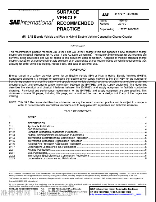
SURFACEVEHICLERECOMMENDEDPRACTICEJ1772™ JAN2010Issued1996-10Revised 2010-01Superseding J1772™NOV2001 (R) SAE Electric Vehicle and Plug in Hybrid Electric Vehicle Conductive Charge CouplerRATIONALEThis recommended practice redefines AC Level 1 and AC Level 2 charge levels and specifies a new conductive charge coupler and electrical interfaces for AC Level 1 and AC Level 2 charging. The coupler and interfaces for DC charging are currently being developed and will be added to this document upon completion. Adoption of multiple standard charge couplers based on charge level will enable selection of an appropriate charge coupler based on vehicle requirements thus allowing for better vehicle packaging, reduced cost, and ease of customer use.FOREWORDEnergy stored in a battery provides power for an Electric Vehicle (EV) or Plug In Hybrid Electric Vehicles (PHEV).Conductive charging is a method for connecting the electric power supply network to the EV/PHEV for the purpose of 零点花园标准区欢迎您!/bbs/?fromuid=3554433.DEFINITIONS (7)3.1AC Level 1 Charging (7)3.2AC Level 2 Charging (7)3.3Charger (7)3.4Chassis Ground (7)3.5Conductive (7)3.6Connector (Charge) (7)3.7Contact (Charge) (7)3.8Control Pilot (7)3.9Coupler (Charge) (8)3.10DC Charging (8)3.11Electric Vehicle (EV) (8)3.12Electric Vehicle Supply Equipment (EVSE) (8)3.13Equipment Ground (Grounding Conductor) (8)3.14EV/PHEV Charging System (8)3.15Insulator (8)3.16Off-Board Charger (8)3.17On-Board Charger (8)3.18Plug In Hybrid Electric Vehicle (PHEV) (8)3.19Vehicle Inlet (Charge) (9)4.GENERAL CONDUCTIVE CHARGING SYSTEM DESCRIPTION (9)4.1AC Level 1 and AC Level 2 Interface Functions (9)4.2AC Level 1 Charging (11)4.3AC Level 2 Charging (12)4.4DC Charging (12)5.CONTROL AND DATA (12)5.1Typical Control Pilot Circuit (13)5.2Equivalent Control Pilot Circuit (13)5.3Control Pilot Functions (15)5.3.1Verification of Vehicle Connection (15)5.3.2EVSE Ready to Supply Energy (15)5.3.3EV/PHEV Ready to Accept Energy (15)5.3.4Determination of Indoor Ventilation (15)5.3.5EVSE Current Capacity (15)5.3.6Verification of Equipment Grounding Continuity (17)5.4Proximity Detection (17)5.5Digital Data Transfer (18)5.6Typical Start Up Sequence (20)6.GENERAL EV/PHEV REQUIREMENTS (21)6.1EV/PHEV Cable Ampacity Coordination (21)6.2Environmental (22)7.GENERAL EVSE REQUIREMENTS (22)7.1EVSE Electromagnetic Emissions (22)7.1.1EVSE Conducted Emissions (22)7.1.2EVSE Radiated Emissions (22)7.2EVSE Electromagnetic Immunity (22)7.3EVSE Electrostatic Discharge (24)7.4EVSE Harmonic Distortion Immunity (24)7.5EVSE Electrical Fast Transient Immunity (24)7.6EVSE Voltage Dips, Short Interruptions and Voltage Variations Immunity (24)7.7EVSE Magnetic Field Immunity (24)7.8EVSE Capacitor Switching Transient Test (24)7.9EVSE Voltage Surge Test (24)7.10Installation Requirements (25)7.11General Product Standards (25)7.12Personnel Protection System (25)7.13AC Present Indicator (25)7.14Conductor Cord Requirements (25)7.15Coupler Requirements (25)8.COUPLER REQUIREMENTS (25)8.1Vehicle Inlet/ Connector Compatibility (25)8.2Ergonomic Requirements (25)8.2.1Ease of Use (25)8.2.2Indexing (25)8.2.3Alignment (26)8.2.4Tactile Feel (26)8.2.5Latching (26)8.3Safety Requirements (26)8.3.1Isolation (26)8.3.2Exposure of Contacts (26)8.3.3Sharp Edges (26)8.3.4Touch Temperature (26)8.3.5Hazardous Conditions (26)8.3.6Unauthorized Access (26)8.4Performance Requirements (26)8.4.1Design Life (27)8.4.2Impact Resistance (27)8.4.3Vehicle Drive-Over (27)8.5Environmental Requirements (27)8.5.1General Environmental Considerations (27)8.5.2Temperature Range (27)8.5.3Temperature Rise (27)8.5.4Insulation Resistance (27)8.5.5Fluid Resistance (27)8.5.6Mechanical Requirements (27)8.5.7Sealing Requirements (28)8.6General Coupler Physical Description (28)8.6.1Vehicle Inlet General requirements (28)8.6.2Connector General Requirements (29)8.7Dimensional Requirements (29)8.7.1Interface Contacts Sizing (29)8.7.2Vehicle Inlet Physical Dimensions (29)8.7.3Connector Physical Dimensions (29)8.7.4Vehicle Inlet Access Zone (29)8.7.5Contact Sequencing (29)9.CHARGE STATUS INDICATOR (30)10.CONNECTOR / VEHICLE INLET OPTIONAL MARKING (30)11.NOTES (30)11.1Marginal Indicia (30)APPENDIX A HISTORY EVSE/VEHICLE INTERFACE (31)APPENDIX B AC LEVEL 3 CHARGING (34)APPENDIX C PREVIOUS CHARGE COUPLER DESIGNS (37)APPENDIX D CHARGE COUPLER DIMENSIONAL REQUIREMENTS (NON LOCKABLE) (43)APPENDIX E CHARGE COUPLER DIMENSIONAL REQUIREMENTS (LOCKABLE) (49)1. SCOPEThis SAE Recommended Practice covers the general physical, electrical, functional and performance requirements to facilitate conductive charging of EV/PHEV vehicles in North America. This document defines a common EV/PHEV and supply equipment vehicle conductive charging method including operational requirements and the functional and dimensional requirements for the vehicle inlet and mating connector.2. REFERENCES2.1 Applicable PublicationsThe following publications form a part of this specification to the extent specified herein. Unless otherwise indicated, the latest issue of SAE and other applicable publications shall apply.Publications2.1.1 SAEAvailable from SAE International, 400 Commonwealth Drive, Warrendale, PA 15096-0001, Tel: 877-606-7323 (inside USA and Canada) or 724-776-4970 (outside USA), .SAE J1113-21 Electromagnetic Compatibility Measurement Procedure for Vehicle Components—Part 21: Immunity to2.1.4 InternationalElectrotechnical Commission PublicationAvailable from International Electrotechnical Commission, 3, rue de Verambe, P.O. Box 131, 1211 Geneva 20, Switzerland, Tel: +41-22-919-02-11, www.iec.ch.IEC Publications are also available from the American National Standards Institute, 25 West 43rd Street, New York, NY 10036-8002, Tel: 212-642-4900, .CISPR 12 Vehicles, boats and internal combustion engines—Radio disturbance characteristics—Limits and methods of measurement for the protection of off-board receivers61000-4-6 Electromagnetic compatibility (EMC)—Part 4-6: Testing and measurement techniques—Immunity to conducted disturbances, induced by radiofrequency fields2.1.5 International Standards Organization PublicationAvailable from International Organization for Standardization, 1 rue de Varembe, Case Postale 56, CH-1211 Geneva 20, Switzerland, Tel: +41-22-749-01-11, .Also available from American National Standards Institute, 25 West 43rd Street, New York, NY 10036-8002, Tel:2.2.1 SAEPublicationsAvailable from SAE International, 400 Commonwealth Drive, Warrendale, PA 15096-0001, Tel: 877-606-7323 (inside USA and Canada) or 724-776-4970 (outside USA), .SAE J551-5 Performance Levels and Methods of Measurement of Magnetic and Electric Field Strength from Electric Vehicles, Broadband, 9 kHz to 30 MHzSAE J1742 Connections for High Voltage On-Board Vehicle Electrical Wiring Harness—Test Methods and General Performance RequirementsSAE J1773 SAE Electric Vehicle Inductively Coupled ChargingSAE J1812 Function Performance Status Classification for EMC Immunity TestingSAE J2178-1 Class B Data Communication Network Messages—Detailed Header Formats and Physical Address AssignmentsSAE J2178-2 Class B Data Communication Network Messages—Part 2: Data Parameter Definitions3. DEFINITIONS3.1 AC Level 1 ChargingA method that allows an EV/PHEV to be connected to the most common grounded electrical receptacles (NEMA 5-15R and NEMA 5-20R). The vehicle shall be fitted with an on-board charger capable of accepting energy from the existing single phase alternating current (AC) supply network. The maximum power supplied for AC Level 1 charging shall conform to the values in Table 1. A cord and plug EVSE with a NEMA 5-15P plug may be used with a NEMA 5-20R receptacle. A cord and plug EVSE with a NEMA 5-20P plug is not compatible with a NEMA 5-15R receptacle.3.2 AC Level 2 ChargingA method that uses dedicated AC EV/PHEV supply equipment in either private or public locations. The vehicle shall be fitted with an on-board charger capable of accepting energy from single phase alternating current (AC) electric vehicle supply equipment. The maximum power supplied for AC Level 2 charging shall conform to the values in Table 1.3.3 ChargerAn electrical device that converts alternating current energy to regulated direct current for replenishing the energy of an energy storage device (i.e., battery) and may also provide energy for operating other vehicle electrical systems.3.4 Chassis GroundThe conductor used to connect the non-current carrying metal parts of the vehicle high voltage system to the equipment ground.3.5 ConductiveHaving the ability to transmit electricity through a physical path (conductor).3.6 Connector (Charge)A conductive device that by insertion into a vehicle inlet establishes an electrical connection to the electric vehicle for the purpose of transferring energy and exchanging information. This is part of the coupler.3.7 Contact (Charge)A conductive element in a connector that mates with a corresponding element in the vehicle inlet to provide an electrical path.3.8 Control PilotAn electrical signal that is sourced by the Electric Vehicle Supply Equipment (EVSE). Control Pilot is the primary control conductor and is connected to the equipment ground through control circuitry on the vehicle and performs the following functions:a. Verifies that the vehicle is present and connectedb. Permits energization/de-energization of the supplyc. Transmits supply equipment current rating to the vehicled. Monitors the presence of the equipment grounde. Establishes vehicle ventilation requirements3.9 Coupler (Charge)A mating vehicle inlet and connector set.3.10 DC ChargingA method that uses dedicated direct current (DC) EV/PHEV supply equipment to provide energy from an appropriate off-board charger to the EV/PHEV in either private or public locations.3.11 Electric Vehicle (EV)An automotive type vehicle, intended for highway use, primarily powered by an electric motor that draws from a rechargeable energy storage device. For the purpose of this document the definition in the United States Code of Federal Regulations – Title 40, Part 600, Subchapter Q is used. Specifically, an automobile means:a. Any four wheeled vehicle propelled by a combustion engine using on-board fuel or by an electric motor drawingcurrent from a rechargeable storage battery or other portable energy devices (rechargeable using energy from a source off the vehicle such as residential electric service).b. Which is manufactured primarily for use on public streets, roads, and highways.c. Which is rated not more that 3855.6 kg (8500 lb), which has a curb weight of not more than 2721.6 kg (6000 lb), andwhich has a basic frontal area of not more than 4.18 m2 (45 ft2).3.12 Electric Vehicle Supply Equipment (EVSE)The conductors, including the ungrounded, grounded, and equipment grounding conductors, the electric vehicle connectors, attachment plugs, and all other fittings, devices, power outlets, or apparatuses installed specifically for the purpose of delivering energy from the premises wiring to the electric vehicle. Charging cords with NEMA 5-15P and NEMA 5-20P attachment plugs are considered EVSEs.3.13 Equipment Ground (Grounding Conductor)A conductor used to connect the non-current carrying metal parts of the EV/PHEV supply equipment to the system grounding conductor, the grounding electrode conductor, or both, at the service equipment.3.14 EV/PHEV Charging SystemThe equipment required to condition and transfer energy from the constant frequency, constant voltage supply network to the direct current, variable voltage EV/PHEV traction battery bus for the purpose of charging the battery and/or operating vehicle electrical systems while connected.3.15 InsulatorThe portion of a charging system that provides for the separation, support, sealing, and protection from live parts.3.16 Off-Board ChargerA charger located off of the vehicle.3.17 On-Board ChargerA charger located on the vehicle.3.18 Plug In Hybrid Electric Vehicle (PHEV)A hybrid vehicle with the ability to store and use off-board electrical energy in a rechargeable energy storage device.3.19 Vehicle Inlet (Charge)The device on the electric vehicle into which the connector is inserted for the purpose of transferring energy and exchanging information. This is part of the coupler.4. GENERAL CONDUCTIVE CHARGING SYSTEM DESCRIPTIONIn the most fundamental sense, there are 3 functions, 2 electrical and 1 mechanical, that must be performed to allow charging of the EV/PHEV battery from the electric supply network. The electric supply network transmits alternating current electrical energy at various nominal voltages (rms) and a frequency of 60 Hz. The EV/PHEV battery is a DC device that operates at a varying voltage depending on the nominal battery voltage, state-of-charge, and charge/discharge rate. The first electrical function converts the AC to DC and is commonly referred to as rectification. The second electrical function is the control or regulation of the supply voltage to a level that permits a managed charge rate based on the battery charge acceptance characteristics – i.e., voltage, capacity, electrochemistry, and other parameters. The combination of these two functions are the embodiment of a charger. The mechanical function is the physical coupling or connecting of the EV/PHEV to the EVSE and is performed by the user. The conductive charging system consists of a charger and a coupler. The conductive system architecture is suitable for use with electrical ratings as specified in Table 1 and as shown in Figure 1.TABLE 1 - CHARGE METHOD ELECTRICAL RATINGS (NORTH AMERICA)FIGURE 2 - AC LEVEL 1 AND AC LEVEL 2 CONDUCTIVE COUPLER CONTACT INTERFACE FUNCTIONSTABLE 2 - AC LEVEL 1 AND AC LEVEL 2 CONDUCTIVE COUPLER CONTACT FUNCTIONSConnector Function DescriptionAC Power (L1) Power for AC Level 1 and 2AC Power (L2,N) Power for AC Level 1 and 2Equipment ground Connect EVSE equipment grounding conductor toEV/PHEV chassis ground during charging Control pilot Primary control conductor (operation described inProximity Detection Allows vehicle to detect presence of charge connector4.2 AC Level 1 ChargingA method of EV/PHEV charging that extends AC power from the most common grounded electrical receptacle to an on-board charger using an appropriate cord set, as shown in Figure 3 at the electrical ratings specified in Table 1. AC level 1 allows connection to existing electrical receptacles in compliance with the National Electrical Code - Article 625.FIGURE 3 - AC LEVEL 1 SYSTEM CONFIGURATIONFigure Illustrates Vehicle Charging4.3 AC Level 2 ChargingThe primary method of EV/PHEV charging that extends AC power from the electric supply to an on-board charger from a dedicated EVSE as shown in Figure 4. The electrical ratings are similar to large household appliances and specified in Table 1. AC Level 2 may be utilized at home, workplace, and public charging facilities.5.1 Typical Control Pilot CircuitA typical control pilot circuit is shown in Figure 5.FIGURE 5 - TYPICAL CONTROL PILOT CIRCUITEquivalent Control Pilot CircuitThe equivalent control pilot circuit and vehicle states are shown in Figure 6 and defined in Table 3, Table 4, and Table 5.TABLE 3 - DEFINITION OF VEHICLE STATESVehicle State Designation Voltage (vdc Nominal) Description of Vehicle State State A 12.0(1)Vehicle not connectedState B 9.0(2)(3)Vehicle connected / not ready to accept energyState C 6.0(2)Vehicle connected / ready to accept energy / indoorcharging area ventilation not required State D 3.0(2)Vehicle connected / ready to accept energy / indoorcharging area ventilation required State E 0 EVSE disconnected, utility power not available, orother EVSE problemState F –12.0(1)EVSE not available, or other EVSE problem1. Static voltage.2. Positive portion of 1 KHz square wave, measured after transition has fully settled.3. From a transition from State A to State B begins as a static DC voltage which transitions to PWM upon the EVSE detection of vehicleconnected / not ready to accept energy.TABLE 4 - EVSE CONTROL PILOT CIRCUIT PARAMETERS (SEE FIGURE 6)TABLE 5 - EV/PHEV CONTROL PILOT CIRCUIT PARAMETERS (SEE FIGURE 6)Parameter(1)Symbol Units Nominal value Maximum value Minimum valueR2B Ohms 2740 2822(2) 2658(2) Equivalent loadresistance – State BR2C Ohms 882 908(2) 856(2) Equivalent loadresistance – State C(3)R2D Ohms 246 253(2) 239(2) Equivalent loadresistance – State D(4)Total equivalent capacitance C2 picofarads n.a. 2400 n.a.Equivalent diode voltage drop(5) Vd Volts 0.70 0.85 0.551. Tolerances to be maintained over the environmental conditions and useful life as specified by the manufacturer.2. Maximum and minimum resistor values are ±3% about nominal.3. Vehicles not requiring ventilation for indoor charging areas.4. Vehicles not requiring ventilation for indoor charging areas.5. Silicon small signal diode, –40 °C to 85 °C, forward current 2.75 to 10.0 ma.5.3 Control Pilot FunctionsThe control pilot performs the following functions.5.3.1 Verification of Vehicle ConnectionThe EVSE is able to determine that the connector is inserted into the vehicle inlet and properly connected to the EV/PHEV by sensing resistance R3 as shown in Figures 3, 4, and 5. The diode, D1, is present to help an EVSE determine that an EV/PHEV is connected rather than other potential low impedance loads.5.3.2 EVSE Ready to Supply EnergyThe EVSE is able to indicate to the EV/PHEV that it is ready to supply energy by turning on the oscillator and providing the square wave signal specified in Figure 7. The EVSE shall not close contactors unless the oscillator is on and valid per Figure 7. In each of the states specified in Table 3, the EVSE may supply the pilot as a DC signal or as an oscillating signal. However, normally the oscillator is only turned on in State B, State C, or State D. Oscillation in other states should only be transitory as specified in Table 8.5.3.3 EV/PHEV Ready to Accept EnergyThe EV/PHEV indicates that it is ready to accept energy from the EVSE by closing switch S2, as shown in Figures 3, 4, and 5, when the current profile on the control pilot oscillator is sensed. The EV/PHEV may de-energize the EVSE at any time by opening switch S2.5.3.4 Determination of Indoor VentilationThe EVSE is able to determine if the EV/PHEV requires indoor charging ventilation by sensing the voltage as specified in Table 3. If required, the EVSE will provide a signal to turn on the indoor charging area ventilation system according to National Electrical Code – Article 625.5.3.5 EVSE Current CapacityThe EVSE communicates the maximum available continuous current capacity to the EV/PHEV by modulating the pilot duty cycle as described in Table 6A, Table 6B and shown in Figure 7.The overall (EVSE and EV/PHEV) control pilot tolerance is not to exceed ±2%. This tolerance is distributed up to ±0.5% for the EVSE and up to 1.5% for the EV/PHEV. In the case of overlapping ranges, the valid state takes precedence over the error state.Based on an overall tolerance of 2% duty cycle (see Table 6B):5.3.5.1 If the EV/PHEV reads a duty cycle of 3-7%, the EV/PHEV shall interpret this as a valid digital communicationscommand. See 5.5.5.3.5.2 If the EV/PHEV reads a duty cycle between 8% and less than 10%, the EV/PHEV should interpret this as avalid 10% duty cycle.5.3.5.3 If the EV reads a duty cycle less than or equal to 85.0% the EV/PHEV should base the current on the Amps =(% duty cycle) * 0.6 formula.5.3.5.4 If the EV reads a duty cycle greater than 85.0%, the EV/PHEV should base the current on the Amps = (% dutycycle - 64) * 2.5 formula.5.3.5.5 If the EV reads a duty cycle of 97%, it is recommended the EV/PHEV consider this as a valid 96% duty cycle.TABLE 6A - EVSE NOMINAL CONTROL PILOT DUTY CYCLEEVSE Nominal Duty Cycle EVSE Commanded Maximum CurrentDuty Cycle < 5% Error state, no charging allowedTABLE 8 - EVSE AND EV/PHEV RESPONSE TIME SPECIFICATIONS2. The transition from any State to State A indicates the vehicle connector has been removed. For safety reasons, it isimportant to de-energize the connector.3. The transition from any State to State E or State F is an indication that the connector has been removed or that theEVSE is not available. For safety reasons, it is important that the vehicle goes into a safe state.4. After a transition from any State to State A, the EVSE should turn off the oscillator (S1). For the purpose of filteringand reasonable control response time, the EVSE will not turn off the oscillator immediately. The connector may be immediately reinserted into the vehicle, and the EV/PHEV could see State C or State D with the oscillator turned on and no AC energy transfer for the listed maximum time before the oscillator is turned off.5. After the vehicle closes S2 in order to request AC energy transfer, the vehicle can expect the contactor to close withina specified time period.6. After the vehicle opens S2, in order to stop requesting AC energy transfer, it can expect the contactor to open within aspecified time period.7. The vehicle must respond to the pilot signal voltages. In this case, the EVSE may be experiencing a power outage,ground fault, or other condition that requires termination of the AC energy transfer mode. The vehicle should respond by opening the S2 and entering a safe mode.8. If the EVSE is experiencing a condition that requires termination of the AC energy transfer mode, the EVSE mustopen the contactor in less than 3 seconds from setting the pilot signal to a state that prevents the EVSE contactor from closing.9. The vehicle must respond to a pilot signal frequency that is significantly out of tolerance. The frequency of the EVSEoscillator is used to verify connection to a compatible EVSE and proper operation of the EVSE. If the frequency is incorrect, the vehicle should respond by opening the S2 and entering a safe mode. The recommended tolerance is ±2%, 1020 Hz to 980 Hz.10. It is common for EVSE equipment to support an input signal for the purpose of external load control (utility serviceinterrupt signal, etc.). This input is used for various purposes including off peak charging support, utility load shedding, and building load management controllers. A maximum response time must be specified to guarantee universal compatibility with the external controlling equipment.11. The EVSE may modify the pilot signal duty cycle at any time, commanding the EV/PHEV to increase or decrease themaximum AC current draw. The vehicle must adhere to the maximum response time in order guarantee universal compatibility with the external controlling equipment. (See Table 8, Transition 10)12. The EVSE should respond to ventilation state changes of the control pilot.13. Switch S3 opens when the connector latch lever is actuated. This opens the Proximity Circuit. The EV/PHEV shouldterminate charge prior to connector disconnect to prevent connector contact arc damage. Charge resumption after S3 closing is OEM specific.5.6 Typical Start Up SequenceThe charge process shall commence sequentially according to the following steps as the connector is inserted into the vehicle inlet:a. The control pilot activates the EV/PHEV charge controller, the proximity detection activates the drive interlock.b. Verification of EV/PHEV connection is detected by EVSE, by detecting a change from State A to State B. During thisstate change the oscillator is off. See switch S1.c. EVSE indicates that it is ready to supply energy by turning on the oscillator and supplying square wave pilot signal tothe EV/PHEV, State B. See switch S1.d. EV/PHEV indicates that it is ready to accept energy from the EVSE by closing switch S2 and providing vehicleventilation information to the EVSE, State C or State D.e. The EVSE determines that the equipment grounding conductor to the EV/PHEV chassis ground is in place bydetecting the high side of Pilot being in state B, C, or D, while the low side being at –12V.f. The EVSE determines that the EV/PHEV pilot control circuitry is correctly configured by verifying the presence of thediode. The low side of the pilot pulse must be within the range specified in Table 4.g. The EVSE determines if indoor area ventilation is required or not. If indoor charging area ventilation is not requiredthen proceed to the next step. If indoor charging area ventilation is required then 3 conditions can exist with corresponding EVSE responses. They are:a. C ondition 1 – If the EVSE is listed for indoor charging of all vehicles, turn on the indoor area ventilation systemand proceed to the next step.b. C ondition 2 – If the EVSE is listed for outdoor charging of all vehicles, proceed to the next stepc. C ondition 3 – If the EVSE is listed for vehicles not requiring indoor charging area ventilation, terminate theprocess and do not allow energizationh. The EV/PHEV vehicle determines the nature of and available current from the EVSE according to 1 of the following 3conditions by measuring the duty cycle of the signal and proceeding as follows (see 5.3.5.1 – 5.3.5.5 and Table 6B):a. I f the pilot duty cycle is between 10% and 96%, calculate available line current from the duty cycle and proceed tothe next step.b. I f the pilot duty cycle is between 3% and 7%, calculate available line current from the digital data link and proceedto the next step. See 5.5.c. I f the digital data link cannot be established as described in 5.6.h.b, the process must be terminated and the faultcondition displayed by the EVSEi. The EVSE may now energize the system by closing the main power contactor and charging may commence at powerlevels up to rated maximum continuous current of the EVSE for continuous rated conditions, or up to the rating of the protective circuit breaker for non-continuous conditions, or up to the maximum rated current of the EVSE for DC charging as provided by the digital data link. A continuous load is defined as operating at a given level for more than3 hours.j. The pilot signal shall be monitored, and charge current adjusted accordingly, continuously during the charge process.If pilot signal is lost or the pulse width goes outside of the allowable range, the EVSE must terminate the charge process by opening the main contactor and turning off the pilot oscillator. The EVSE should also display the fault condition.k. To terminate the charge process, turn the EVSE on/off switch to the off position and/or remove the connector from the vehicle inlet. See 5.4.6. GENERAL EV/PHEV REQUIREMENTS6.1 EV/PHEV Cable Ampacity CoordinationVehicle cabling used for the AC Mains and Safety Ground should be coordinated with the supply input from the EVSE (known from the Control Pilot duty cycle). The following are examples of possible methods coordination may be achieved:。
sae j2174标准

SAE Technical Standards Board Rules provide that: “This report is published by SAE to advance the state of technical and engineering sciences. The use of this report is entirely voluntary, and its applicability and suitability for any particular use, including any patent infringement arising therefrom, is the sole responsibility of the user.”SAE reviews each technical report at least every five years at which time it may be reaffirmed, revised, or cancelled. SAE invites your written comments and suggestions.TO PLACE A DOCUMENT ORDER: +1 (724) 776-4970 FAX: +1 (724) 776-0790SAE WEB ADDRESS Copyright 2002 Society of Automotive Engineers, Inc.2.2.2TMC P UBLICATIO N—Available from American Trucking Associations, 2200 Mill Road, Alexandria, VA 22314.TMC RP 110—Low Tension Cable for Heavy Duty Truck-Trailer Wiring Systems (sizing and color only)TMC RP 114 – Wiring Harness ProtectionTMC RP 137 – Antilock Electrical Supply from Tractors through the SAE J560 Seven Pin ConnectorTMC RP 141—Trailer ABS Power Supply Requirements2.2.3TTMA P UBLICATION—Available from Truck Trailer Manufacturers Association, 1020 Princess Street,Alexandria, VA 22314.TTMA RP97-97 – Trailer Antilock Braking System WiringTTMA RP111 – Electrical System Maintenance and Repair for Trailers Without Sealed Wiring Harness SystemsTTMA RP119 – Electrical Interface for Truck-Trailer InterconnectionDesign and Installation of Lighting Systems for Trailers2.2.4M ILITA RY S PECIFICATION—Available from Global Engineering Documents, 15 Inverness Way East,Englewood, CO 80112-5704.MIL-STD-1344A—Test Methods for Electrical Connectors3.Definitions3.1Connector—A coupling device which provides an electrical and mechanical junction between twomulticonductor cables, or between a cable and an electrical component.3.2Terminal—A device attached to a wire or cable to provide the electrical interface between two cables or acable and an electrical component.3.3Dolly—A chassis equipped with one or more axles, a fifth wheel and/or equivalent mechanism, and drawbar,the attachment of which converts a semitrailer to a full trailer.3.4Electrical Distribution System—The electrical wiring system includes all cables and wiring, connectors andterminations, coverings, seals, any other incorporated items to maintain the integrity and performance of the electrical system, and the connector to any mating device with the exception of the SAE J560 connector where only the electrical performance requirements apply. The electrical wiring system does not include the functional devices to which the wiring system is attached such as lamps, ABS electronic control modules or sensors.3.5Sealed—A condition which provides a nonleaking union between two mechanical components or any placewithin an electrical distribution system. A sealed union is defined as one which does not allow the ingress of moisture.4.Tests4.1Test Procedures—Conformance to the requirements of this document shall be determined by subjecting eachdevice to each test procedure listed in this document. Unless otherwise stated, the tests are to be performed at 25 °C ± 5 °C and at 12.5 V DC ± 0.1 V DC or per the manufacturers recommendations. Sample sizes shall be statistically valid. The tests shall be conducted in the sequence as follows:4.1.1Voltage Drop4.1.2Connector Durability4.1.3 Salt Fog4.1.4Thermal Cycle4.1.5Thermal Shock4.1.6Oil Absorption4.1.7Salt Water Immersion4.1.8 Spray Wash4.1.9Vibration4.1.10Insulation Resistance - Multiconductor Assemblies4.1.11Tensile Strength - Wire to Terminal4.1.12 Tensile Strength – Wire to Wire4.1.13 Connector Pull Force4.1.14 Connector Misengagement Force4.1.15 Connector Terminal Retention Force4.1.1V OLTAGE D ROP—The measurement of connection voltage drop shall be per SAE J163 and Figures 1 and 2.The voltage drop of the cables shall be subtracted from the measured values. Except for connectors specified by SAE J560, the voltage drop shall be measured at the current specified in Table 1 of this document.FIGURE 1—CABLE TO CABLE ASSEMBLYFIGURE 2—CABLE TO COMPONENT ASSEMBLY4.1.2C ONNECTOR D URAB ILITYa.An assembled connector with terminals shall be mated and unmated 25 times.ing the procedure described in 4.1.1, measure the millivolt drop of the mated terminal pair.4.1.3S ALT F O G—Testing shall be performed per ASTM B 117-73 test method for 96 h. During the test, each circuitshall be operating at the test currents specified in Table 1.4.1.4T HERMAL C YCLE—Connector and cable assemblies shall be connected to their mating parts. Theassemblies shall be exposed to 25 cycles of the thermal cycle profile shown in Figure 3. The assemblies shall be energized with test voltage commencing at point “A” of Figure 3 and de-energized at point “B” of each cycle. The current shall be limited to 1.0 A.FIGURE 3—THERMAL CYCLE PROFILE4.1.5T HERMAL S HOCK—The cable to cable or cable to component connector assemblies shall be subjected to10cycles of thermal shock. One cycle shall consist of 30 min at a temperature of –40 °C ± 2 °C followed by30 min at a temperature of 80 °C ± 2 °C with a transfer time of 2 min maximum.4.1.6O IL A BSORPTION—Connectors shall be capped prior to testing to prevent entry of oil into the connectorcavities during the test. The wiring assembly shall be immersed in ASTM D 471, IRM-902 engine oil at 50 °C ± 3 °C for a period of 20 h. After removal from the engine oil, remove excess oil from the surface and allow sufficient time for excess oil trapped in the assembly to drain completely.4.1.7S ALT W ATER I MMERSIO N4.1.7.1Cable to Cable Assemblya.Immerse the assembly at a minimum depth of 300 mm in a 5% solution of salt (sodium chloride) water.b.Extend the cable ends out of the solution.c.Connect the assembly to a source set at test voltage. The current flowing shall be a minimum of 1.0 A.d.Energize the assembly for 30 min each hour.e.Terminate test after 60 h.4.1.7.2Cable to Component Assemblya.Immerse the assembly at a minimum depth of 300 mm in a 5% solution of salt (sodium chloride) water.b.Extend the ends of the cable assembly out of the solution.c.Connect the assembly to a source set at component rated voltage or test voltage.d.Energize the assembly for 30 min each hour.e.Terminate test after 60 h.4.1.8S PRAY W ASH—Conduct testing per SAE J1455. The addition of detergents or other additives to the water isrecommended. The sample should be oriented in an as installed condition, simulating normal operating conditions.4.1.9V IBRATIO N4.1.9.1Applicability—It is difficult to subject a complete trailer wiring system to a vibration test due to its size. Toaccomplish a meaningful test, individual sections need to be tested alone or along with other sections.Each connector system as well as each mounting support location must be tested. Unsupported sections routed around tight corners or passing through cutouts should also be tested.4.1.9.2Test Set Up—The section of wiring under test shall be attached to the shaker table simulating the actualinstallation. The remainder of the wiring shall be free and unsupported for a minimum of one vertical meter, draped off the test table. If the section under test may accumulate ice during actual usage, a 2 kg weight shall be added to the free wiring, one half meter below the surface of the shaker table.4.1.9.3Test Method—Alternative test methods, 4.1.9.3.1 or 4.1.9.3.2, may be applied depending upon availabilityof equipment. Method 4.1.9.3.1 is recommended.With 100 mA flowing through the circuits under test during the last thirty minutes of the test, monitor each circuit for discontinuities.Measure millivolt drop at the termination of the test using the procedure described in 4.1.1.4.1.9.3.1Vibration testing shall be performed by the procedure described in SAE J2139.4.1.9.3.2Vibration testing shall be performed by the procedure described in SAE J1455, sine sweep profile from10 to 1000 Hz, single axis for 6 h.4.1.10I NS ULATION R ESISTANCE—M ULTICONDUCTO R A SSEMBLIES—Using a 500 V megohmmeter or 500 V, AC or DC,hipotential tester, check each terminal to all other terminals and any conducting shells or conduits.4.1.11T ENSILE S TRENGTH—W IRE TO T ERMINAL—If insulation crimps are present, the crimp wings shall be openedbefore testing. The terminal and wire assembly shall be placed in a wire terminal pull tester. Sufficient force shall be applied to pull the wire out of the terminal or break the wire. All testing is to be conducted at a uniform rate of speed not to exceed 305 mm/min.4.1.12T ENSILE S TRENGTH—W IRE TO W IRE—The wire to wire splice shall be placed in a pull tester. Sufficient forceshall be applied to break the wire or break the wire to wire splice. All testing is to be conducted at a uniform rate of speed not to exceed 305 mm/min.4.1.13C ONNECTOR P ULL F ORCE—All mated connectors that may be subjected to disconnection forces during useshall have a force of 100 N applied in the axis of engagement of the connector pair in the direction of disengagement. The force shall be applied at a rate not to exceed 5 N/s.4.1.14C ONNECTOR M IS ENG AGEMENT F ORCE—Unmated multicavity connector pairs shall have a force of 178 Napplied in the axis of and in the direction of engagement. The connectors shall be oriented to test the mechanical strength of the connector system's polarization features.4.1.15T ERMINA L R ETE NTION TENSILE F ORCE—The terminal retention force within the connector cavity shall bedetermined by applying and measuring a tensile load along the axis of the terminal. The load should be applied to the attached conductor .5.Requirements5.1Voltage Drop—The voltage drop shall not exceed the values tabulated in Table 1:TABLE 1—VOLTAGE DROPSAE Cable Size(mm2)Test Current(Amperes)MaximumMillivolt Drop(cable to device)(cable to cable)0.551000.8101001.0151002.0201003.030100 5.040100 8.050100 13.0601005.2Tensile Strength—Wire to Terminal—The tensile strength shall exceed the values listed in Table 2 for an effective electrical and mechanical connection.5.3Tensile Strength—Wire to Wire—The tensile strength shall exceed the values listed in Table 2 for an effective electrical and mechanical connection.5.4Connector Durability—The millivolt drop shall not exceed the values listed in Table 1 for the wire size under evaluation. At the conclusion of the test, there shall be no evidence of cracking, breaking or physical deformation that would affect performance in the other required tests.5.5Vibration—The millivolt drop shall not exceed the values listed in Table 1 for the wire size under consideration. There shall be no apparent loosening of terminals within a connector. There shall have been no electrical discontinuities greater than 100 Ω for greater than 10 µs in the last half hour of the test. There shall be no signs of mechanical or electrical damage or defects upon visual examination.5.6Thermal Cycle—Upon completion of the thermal cycle exposure, there shall be no cracking, warping, or rupture of any of the components. The connectors shall remain serviceable.5.7Thermal Shock—There shall be no evidence of damage detrimental to the normal operation of the assembly.5.8Oil Absorption—Upon completion of the oil absorption tests, the connectors must remain serviceable. A serviceable part is one that can be removed with reasonable force and reinstalled without visible damage. A visual inspection shall reveal no cracks, splits, or other damage to the items used in the construction of the assembly.5.9Insulation Resistance—The insulation resistance shall be in excess of 1 M Ω. The leakage current shall be less than 50 mA.5.10Salt Water Immersion—At the completion of the test, there shall be no visual evidence of corrosion residueon any of the electrical terminals and the terminals shall be intact in their original condition.Allow the assembly to dry for 4 h after concluding the test and check each circuit for shorting between circuits and grounding to any conducting shell or conduit.5.11Salt Fog—At the completion of the test, there shall be no visual evidence of corrosion residue on any of theelectrical terminals and the terminals shall be intact in their original shape.Allow the assembly to dry for 4 h after test and check each circuit for shorting between circuits and grounding to any conducting shell or conduit.TABLE 2—MINIMUM TENSILE STRENGTHSAE Cable Size(mm 2)Force (N)(Wire to Terminal)(Wire to Wire)0.5700.88011242155317752008222133555.12Spray Wash—Upon visual examination at the conclusion of the test, there shall be no evidence of wateringress into any sealed cavities, particularly connector cavities and sealed cables.5.13Connector Pull Force—The mated connectors shall withstand the specified load for a minimum of 30 swithout any damage or disengagement.5.14Connector Misengagement Force—The connectors shall withstand the specified load for a minimum of 30 swithout any damage, without connector engagement, and without electrical connection in any terminal position.5.15Terminal Retention Tensile Force—The minimum terminal retention tensile force shall meet the minimumrequirements as specified in Table 3. Note that the retention force includes secondary locking devices if provided. The harness designer shall be responsible for determining the application of Standard or Heavy-Duty ratings.6.Design Requirements6.1All single conductor primary wire shall conform to the requirements of SAE J1128 excluding the thin wall types TWP, TXL and TWE. Consideration should be given to more stringent cold bend requirements in locations where flexing occurs. Wherever possible, all conductors shall be grouped together in a suitable conduit or jacket to protect them from detrimental environmental conditions. All seven conductor ABS power cables shall conform to the performance requirements of SAE J2394.6.2Wire sizes for the main and all branch circuits shall be sufficient to provide all electrical components with component design voltage or component manufacturer's recommended voltage. Particular attention should be paid to any components with safety related functions such as ABS, lighting, etc.6.3Wire and cable assemblies shall be designed such that all uninsulated terminals are on the ground side of each connection. This applies to terminals which may be insulated in their connected state but which are uninsulated should a disconnect occur.6.4Noncorrosive flux must be used during any solder operation performed on any wire or cable assembly or component. Acid core solders or acid based fluxes must not be used.6.5If terminals are soldered to the wires, solder shall not wick under the insulation beyond the end of the terminal insulation support.6.6Connectors shall be polarized to assure proper mating when circuit polarization is necessary. 6.7When exposed to water or condensation, connectors shall be sealed.TABLE 3—MINIMUM TERMINAL RETENTION IN CONNECTOR CAVITYCable Size (mm 2)Minimum Pull Force (N)StandardMinimum Pull Force (N)Heavy Duty0.553890.85389153111253111353133553133853155131001556.8All terminals shall incorporate a corrosion resistant plating, and wherever possible, incorporate an insulation crimp.6.9Conductor splices shall be sealed, located in regions of the harness where flexing does not occur, and located within covered areas of the harness.6.10Conductor sizes for the main and all branch circuits shall be determined by the voltage drop method using thefollowing equation:(Eq. 1)whereVD = Maximum allowable voltage drop (volts)L = Total length of the copper circuit (mm),NOTE—Consider the use of doubles, triples and dollies when calculating the overall lengthI = Maximum steady-state current in circuit (A)Calculate cable resistance [R] in micro ohms/mm and locate the cable size in Table 4. If the resistance falls between two conductor sizes, specify the larger conductor.6.11The electrical distribution system and its added-on components shall conform to the requirements of thisdocument when subjected to the test procedures outlined in this document. The electrical distribution system may support specific components which impose additional more stringent performance requirements which must also be met.7.Installation Requirements7.1The edges of all metal members through which wire and cable passes, shall be deburred and rolled or covered with a durable protective covering. The insulated conductors shall be protected to prevent cutting, pinching, or abrasion at any point in the system.7.2Wire and cable shall be mechanically and electrically secure. When necessary, clips for retaining cables and wires shall be permanently attached to the body or frame members and shall hold the wire and cable permanently without cutting into the insulation.7.3Wire and cable shall be protected from moving mechanisms, snags, excessive heat, road splash, stones,grease, oil, and fuels. Wire and cable exposed to such conditions shall be protected by the use of heavy wall insulation and/or additional tubing resistant to the hazards. Other methods which provide protection are acceptable.TABLE 4—CONDUCTOR SIZING (REFERENCE SAE J2202)Cable Size (mm 2)Resistance at 20 °C Micro Ohms/mm0.535.20.822.2115.129.183 5.855 3.78 2.37131.48R VD ()10+6×[]L l ×[]÷=7.4Dielectric compound at terminals and connectors is not considered to be a primary sealing mechanism. Allcomponents intended for use with a sealed electrical distribution system for trailers shall have features which maintain the sealed characteristics of the system. If used, the dielectric compound shall not adversely affect the function of the device. Dielectric compounds may cause connector seals to swell resulting in an adverse change in performance.7.5Use of dissimilar metals which can encourage galvanic corrosion must be avoided.8.Guidelines8.1Electrical tape should not be used for sealing or insulation.8.2Terminals shall be used and applied per the manufacturer's specifications. Terminals designed for fullyautomated assembly operations are preferred over manually assembled parts to assure consistent, high quality terminations8.3If soldered terminals are used, care should be taken to adhere to the manufacturer's recommendations.8.4Spray wash equipment in common use often is at significantly higher pressure than the performancerequirements in this specification. It is recommended that additional connector protection be provided to address any avenues of water entry into connector cavities if the connector location in the application may be subject to this high pressure spray wash equipment.8.5To minimize voltage drop and current requirements for double and triple trailer combinations, the use of lowcurrent lighting devices such as LED lamps is recommended.8.6Oxides on the surface of non-noble terminal contact plating may affect voltage drop when operated at lowvoltages or currents. If circuits operate at less than 5 volts or less than 0.5 amps in the operation of a component, then the component manufacturer should be consulted to assure that adequate testing is performed to assure proper operation of the device.9.Notes9.1Marginal Indicia—The change bar (l) located in the left margin is for the convenience of the user in locatingareas where technical revisions have been made to the previous issue of the report. An (R) symbol to the left of the document title indicates a complete revision of the report.PREPARED BY THE SAE TRUCK AND BUS ELECTRICAL SYSTEMS SUBCOMMITTEE OF THESAE TRUCK AND BUS ELECTRICAL/ELECTRONIC COMMITTEERationale—The trailer electrical system has always been considered to be primary to transportation safety. It is an absolute necessity to have a durable system which supplies sufficient power to the trailer electrical components. Safety considerations must be applied to single trailers, doubles, triples and dollies.The task force has studied the durability and the power issues and developed this SAE Standard from the prior Recommended Practice. Since this document includes procedures and data which have gained broad acceptance, it is being requested that it be approved as an SAE Standard.First and foremost, this rewrite addressed the concerns expressed by the National Highway Traffic Safety Administration regarding the finding that some multiple configurations did not provide adequate power to ABS, or stop lamp circuits. To address this concern, a method to determine the appropriate conductor sizing was added to the Design Requirements.The task force, understanding the application and environmental requirements of Heavy-Duty Wiring Systems for Trailers, recognized the need for additional test requirements. Specifically, Salt Fog, Spray Wash, Tensile Strength - Wire to Wire, Connector Pull Force, Connector Misengagement Force and Connector Terminal Retention Force were added.Certain tests were in need of improvement. The temperature range of the Thermal Shock test was extended to –40 °C from –30 °C and to 80 °C from 75 °C. The Oil Absorption test was more clearly defined. Vibration testing now references standard test methods, the test set up was clarified, and discontinuities were defined. Table 2 - Minimum tensile Strength was added. Additionally, The Design Requirements and Guidelines Sections were significantly expanded.Relationship of SAE Standard to ISO Standard—Not applicable.Application—This SAE Standard establishes the minimum performance requirements for electrical distribution systems for use in dollies and trailers in single or multiple configurations.Reference SectionSAE J163 - Low Tension Wiring and Cable and Splice ClipsSAE J560—Seven Conductor Electrical Connector for Truck-Trailer Jumper CableSAE J575—Tests for Motor Vehicle Lighting Devices and ComponentsSAE J1128—Low Tension Primary CableSAE J2139— Tests for Lighting Devices and Components Used on Vehicles 2032 mm or more in Overall WidthSAE J2202 – Heavy-Duty Wiring Systems for On-Highway TrucksSAE J2247 - Truck Tractor Power Output for Trailer ABSSAE J2394 – Seven Conductor Cable for ABS PowerASTM B 117—Standard Method of Salt Spray (Fog) TestingASTM D 471-Standard Test Method for Rubber Property-Effect of LiquidsMIL-STD-1344A, Method 3002.1 - Low-Signal Level Contact ResistanceTMC RP 110—Low Tension Cable for Heavy Duty Truck-Trailer Wiring SystemsTMC RP 114 – Wiring Harness ProtectionTMC RP 137 – Antilock Electrical Supply from Tractors through the SAE J560 Seven Pin ConnectorTMC RP 141 - Trailer ABS Power Supply RequirementsTTMA RP97-97 – Trailer Antilock Braking System WiringTTMA RP111 – Electrical System Maintenance and Repair for Trailers Without Sealed Wiring Harness SystemsTTMA RP119 – Electrical Interface for Truck-Trailer InterconnectionDesign and Installation of Lighting Systems for TrailersDeveloped by the SAE Truck and Bus Electrical Systems SubcommitteeSponsored by the SAE Truck and Bus Electrical/Electronic Committee。
赛米控丹佛斯 SEMIPACK 晶闸管 二极管模块 SKKD 101 16 数据表

Rev. 3.0–31.05.20221®1SKKDRectifier Diode ModulesSKKD 101/16Features*•Heat transfer through aluminium oxide ceramic insulated metal baseplate •UL recognized, file no. E63532Typical Applications•Non-controllable rectifiers for AC/AC converters•Line rectifiers for transistorized AC motor controllers•Field supply for DC motorsAbsolute Maximum Ratings SymbolConditionsValuesUnitRecitifier DiodeI FAV sin. 180°T j max =130°C T c =85°C 134A T c =100°C 101A I FSM 10ms T j =25°C 2500A T j =130°C 2000A i 2t10ms T j =25°C 31250A²s T j =130°C20000A²s V RSM T j =25°C 1700V V RRM T j =25°C1600V T j -40...130°C Module T stg -40 (125)°C V isola.c.; 50 Hz; r.m.s.1min 3000V 1s3600VCharacteristics SymbolConditions min.typ.max.UnitDiode V F T j =25°C,I F =300A 1.45 1.60V V F0T j =130°C 0.750.87V r F T j =130°C 2.202.45m ΩI R T j =130°C, V RRM 3mA R th(j-c)cont.per chip 0.15K/W per module 0.075K/W R th(j-c)sin. 180°per chip 0.2K/W per module0.1K/WModule R th(c-s)chip 0.09K/W module 0.05K/W M s to heatsink M5 4.25 5.75Nm M t to terminals M52.553.45Nm a 5 * 9.81m/s²w75g2Rev. 3.0–31.05.2022© by SEMIKRON© by SEMIKRON Rev. 3.0–31.05.202234Rev. 3.0–31.05.2022© by SEMIKRONThis is an electrostatic discharge sensitive device (ESDS) due to international standard IEC 61340.*IMPORTANT INFORMATION AND WARNINGSThe specifications of SEMIKRON products may not be considered as guarantee or assurance of product characteristics("Beschaffenheitsgarantie"). The specifications of SEMIKRON products describe only the usual characteristics of products to be expected in typical applications, which may still vary depending on the specific application. Therefore, products must be tested for the respectiveapplication in advance. Application adjustments may be necessary. The user of SEMIKRON products is responsible for the safety of their applications embedding SEMIKRON products and must take adequate safety measures to prevent the applications from causing a physical injury, fire or other problem if any of SEMIKRON products become faulty. The user is responsible to make sure that the application design is compliant with all applicable laws, regulations, norms and standards. Except as otherwise explicitly approved by SEMIKRON in a written document signed by authorized representatives of SEMIKRON, SEMIKRON products may not be used in any applications where a failure of the product or any consequences of the use thereof can reasonably be expected to result in personal injury. No representation or warranty is given and no liability is assumed with respect to the accuracy, completeness and/or use of any information herein, including without limitation, warranties of non-infringement of intellectual property rights of any third party. SEMIKRON does not assume any liability arising out of the applications or use of any product; neither does it convey any license under its patent rights, copyrights, trade secrets or other intellectual property rights, nor the rights of others. SEMIKRON makes no representation or warranty of non-infringement or alleged non-infringement of intellectual property rights of any third party which may arise from applications. Due to technical requirements our products may contain dangerous substances. For information on the types in question please contact the nearest SEMIKRON sales office. This documentsupersedes and replaces all information previously supplied and may be superseded by updates. SEMIKRON reserves the right to make changes.SKKD。
177230型号的晓星晃动传感器说明书

DescriptionThe 177230 Seismic Transmitter is a simple, loop-powereddevice that can be quickly and easily installed. It can beintegrated into your programmable logic controller (PLC) orcontrols system linked to a plant asset condition monitoringsolution. Its simple design reduces training, maintenance,and service costs. The transducer helps you better managedowntime, optimize maintenance planning, and avoidunforeseen catastrophic failures of machinery assets.The 177230 Seismic Transmitter incorporates robust CMdesign for reliability and implements an industry-standard 4to 20 mA loop-powered transmitter.Easily Installed and Integratedl Interfaces with PLCs and control systems (includingDCS and SCADA)l Requires only a short learning curve for operations andmaintenance –through a familiar interface similar tothat for connecting other PLC or control system inputsl Requires no field configuration or adjustmentsl Needs few additional parts for a complete systeml Includes technical support for customers on how tomonitor their equipmentl Includes self-testl Incorporates protected interfacel Supports a variety of interface cablesData Qualityl Provides accurate and repeatable datal Uses simple data formatl Provides raw vibration signal for verification andanalysis177230Seismic TransmitterDatasheetBently Nevada Machinery Condition Monitoring177232Rev.OEHS Compliantl Implements safe and ergonomic design l Supports access to hazardous areasSpecifications ElectricalSensitivity – Main Loop (Signal One) n0.0 to 12.7 mm/s (0 to 0.5 in/s) n0.0 to 25.4 mm/s (0 to 1.0 in/s) n0.0 to 50.8 mm/s (0 to 2.0 in/s)± 10% FS, broadband rms (root mean square)[4 ± 0.3 mA equals 0.0 mm/s and 20 ± 2 mA equals 25.4mm/s]Output Format, Pin A Referenced to Pin B 4 to 20 mA current loop Velocity vibrationExcitation Voltage 12 to 30 Vdc (current limited to 40 mA)This product is for use with PLCs, DCS and SCADA systems that have internal power supplies which are typically current limited in the range of 30 mA to 35 mA.Settling Time Less than 15 seconds within 2% of final valueConnector Wiring Convention n Pin A: 4-20 mA Positive Loop n Pin B: 4-20 mA Negative Loop and common for DynamicSignaln Pin C:Dynamic Signal involtage, unbufferedFrequency Response 10 Hz to 1 kHz (600 cpm to 60 kcpm) ± 10%Sensitivity –DynamicSignal(SignalTwo)10.2 mV/m/s2 (100 mV/g) ± 20%Output Format, Pin C Voltage, Acceleration vibrationReferencedto Pin BThe Dynamic Signal Negative (Pin B)requires isolation from any grounding.If this terminal is grounded, the 4-20mA loop will short, resulting in nooutput.FrequencyResponse2.5 Hz to 10 kHz (150 cpm to 600kcpm) ± 10%Linearity ±1%Output BiasReferencedto Pin B2.5 V ± 0.1 VFull ScaleRange147 m/s2 ( 15 g’s) peakVelocityRange (seeOption AAand BB)n0 – 12.7 mm/s (0 – 0.5 in/s)n0 – 25.4 mm/s (0 – 1.0 in/s)n0 – 50.8 mm/s (0 – 2.0 in/s)MountedResonantFrequencyGreater than 12 kHzTransverseSensitivityLess than 5% of sensitivitySensingElementTypeCeramic / ShearEnvironmental LimitsOperatingTemperatureRange-40 °C to +85 °C(-40 °F to +185 °F)ElectricalIsolationGreater than 108 ohmsIsolationBreakdownVoltage600 Vrms with less than 1 mAleakage currentShockSurvivability9.810 m/s2 (1.000 g peak),maximum drop testThis part typically mounts directly tothe machine via a stud. Customerscan use this device with a magneticbase, but must take care not to “snap”the unit onto the machine. Thissnapping action can create a verylarge spike signal that can damagethe electronics. Rolling the magnetic-base onto the machine greatlyreduces the spike signal so that theunit should not have any issues. Sensor Seal Hermetically sealedRelativeHumidity ofTransmitterTo 100% non-submergedMagnetic Field Sensitivity Less than 20 μm/s/gauss (790μin/s/gauss) peakLess than 14.7 mm/s2/gauss(150 μg/gauss) peak[based on 50 gauss, 50 - 60 Hz]PhysicalWeight 131 g (4.62 oz), typicalDiameter 25.4 mm (1.00 in)Height 66.0 mm (2.60 in)CaseMaterial316L stainless steelConnector 3-pin MIL-C-5015, 316L stainlesssteelMountingHole1/4-28 UNFMountingThreadsM6 X 1 SIM8 x 1.25 SI¼-28 UNFThese stud adapters are provided witheach device. For additional adapters,see Ordering Information on page 7. Orcontact Benty Nevada Tech Support.MountingTorque4 to 7 N-m (35.4 to 62.0 in-lbf)Connector Wiring ConventionPin A 4-20 mA Loop Power (Positivewith reference to Pin B)Pin B4-20 mA Loop Return (Negative/return for Dynamic Signal)Pin C Dynamic Signal (Unbuffered,referenced to Pin B)Compliance and CertificationsFCCThis device complies with part 15 of theFCC Rules. Operation is subject to thefollowing two conditions:l This device may not cause harmfulinterference.l This device must accept anyinterference received, includinginterference that may causeundesired operation.EMCEMC Directive 2014/30/EURoHSRoHS Directive 2011/65/EU Maritime330400 and 330425 onlyABS 2009 Steel Vessels Rules1-1-4/7.7,4-8-3/1.11.1,4-9-7/13Hazardous Area ApprovalsFor the detailed listing of country andproduct specific approvals, refer to theApprovals Quick Reference Guide(108M1756) available from . CSA/NRTL/C177230Ex nL IIC T4:AEx nA IIC T4:Class I, Div 2, Groups A, B, C, D.Ex ia IIC T4:AEx ia IIC T4:Class I, Div 1, Groups A, B, C, D;Class II, Div 1, Groups E, F, G;Class III, Div 1Install per drawing 177234T4 @ Ta ≤ 80°C200150,200155,200157Ex ia IIC T4Class I, Div 1Groups A,B,C,DT4 @ -40°C ≤ Ta ≤ 80°CPer DWG 167535Ex nL IIC T4Class I, Div 2Groups A,B,C,DT4 @ -40°C ≤ Ta ≤ 80°CPer DWG 167535200350 (Approval Option 1)IntrinsicallySafeEx ia IIC T4Class I, Division 1, Groups A, B, Cand DAEx ia IIC T4Class I, Division 1, Groups A, B, Cand DT4 @ -54 °C ≤ Ta ≤ +121 °C(-65.2 °F ≤ Ta ≤ 249.8 °F )Per drawing 175825 IntrinsicallySafe andNon-IncendiveEx nL IIC T4Class I, Division 2, Groups A, B, Cand DAEx nA T4Class I, Division 2, Groups A, B, Cand DT4 @ -54 °C ≤ Ta ≤ +121 °C (-65.2 °F≤ Ta ≤ +249.8 °F ) per drawing17582ATEX/IECEx177230Entity ParametersII 1 GEx ia IIC T4 GaII 3 GEx na IIC T4 GcT4@ Ta = -40°C to 80°C Zone 0/1 Zone 2 Ui= 28V Ui= 28V Ii= 120mA Ii= 120mA Pi= 1W Pi= 1W Ci=0Li=121.06µh200150, 200155, 200157Entity ParametersII 1 GEx ia IIC T4 GaII 3 GEx na IIC T4 GcT4@ Ta = -40°C to 80°C Zone 0/1 Zone 2 Ui= 27V Ui= 27V Ii= 150mA Ii= 150mA Ci=16.2 nFLi= 0200350Entity ParametersII 1 GEx ia IIC T4 GaII 3 GEx na IIC T4 GcT4@ Ta = -54°C to +121°CZone 0/1 Zone 2Ui= 28V Ui= 28VIi= 200mA Ii= 200mAPi= 1W Pi= 1WCi=16.2 nFLi= 0Hazardous Area Conditions ofSafe UseATEX/IECExZone 0/1:Equipment must be connected to equipment,which meets the above listed entityparameters.The cables type A or B (in compliance with EN60079-25) must respect the cable parameterslisted with the entity parameters.Zone 2 :The supply electrical parameters shall notexceed the values mentioned in the tablesabove.Ordering InformationFor the detailed listing of country andproduct specific approvals, refer to theApprovals Quick Reference Guide(108M1756) available from . Seismic Transmitter177230-AA-BB-CCA: Measurement Range000 – 12.7 mm/s (0 – 0.5 in/s)010 – 25.4 mm/s (0 – 1.0 in/s)020 – 50.8 mm/s (0 – 2.0 in/s)B: Frequency0110 Hz to 1 kHz (600 to 60 kcps) rms 02 3 Hz to 1 kHz (180 to 60 kcps) pkC: Approvals05Multiple Approvals (CSA/NRTL/C,ATEX/IECEx)Only standard or common AA-BB-CCconfigurations are available. Interconnect Cable without Armor 16925-AAA: Length in feetOrder in increments of 1 foot (0.3 m) Minimum length: 3 feet (0.91 m) Maximum length: 99 feet (30.2m) Example: 25 = 25 feetThese standard lengths are available. You can order custom lengths at additional cost.Interconnect Cable with Armor16710-AAA: Length in feetOrder in increments of 1 foot (0.3 m) Minimum length: 3 feet (0.91 m)Maximum length: 99 feet (30.2m) Example: 25= 25 feetThese standard lengths are available. You can order custom lengths at additional cost.Ordering AccessoriesYou can order these accessories from the vendors named. Contact the vendor with the part number and ask for their part that fits your application.3-Pin Connector (MIL-C-5015)Base Cannon (ITT industries)P/N: CA3106R-10SL-3S F97 orP/N: MS3106R-10SL-3SShell Sunbank Co.Glenair, Inc.Wire (3-wire with shield) Three-conductor 18 to 22 AWG cables with a 0.01” minimum outer jacket and inner wire insulation, and 80% minimum coverage shield. Insulation rating should be 600 V minimum.Mil-W-16878/4 (Type E)Sonic/Thermax 18 AWG - P/N: 18-TE-1930 (3) SXE 22 AWG - P/N: 22-TE-1934 (3) SXEStandard Wire and Cable Co. 18 AWG - P/N: 1100-88T22 AWG - P/N: 1100-66T Belden18 AWG - P/N: 8333622 AWG -P/N: 83334Studs and AdaptersPart No.Description89139-01M-M ¼-28 UNF to ⅜-24 UNFstandard stud128038-01M-M ¼-28 UNF to ⅜-24 hexplate stud (1-⅜” X 0.25”) 146396-01F-M ¼-18 NPT to ¼-28 adapter 146394-01F-M ¼-28 UNF to ¼-18 NPTadapter37439-01F-M ¼-28 UNF to ¼-28 UNFmounting base164373 M-M ¼-28 UNF to ¼-28 UNFstandard stud with brass tip 135826-01M-M ¼-28 UNF to M10 X 1.0standard studGraphs and FiguresDimensions shown in mm (inches) except as noted.A. Positive loop (4-20 mA)B. Negative loop (4-20 mA) and common for dynamic signalC. Dynamic signalD. 3-pin MIL-C-5015, 5/8-24 UNEF-2AE. 66.0 mm (2.60 in)F. 1.27 mm (0.050 in)G. 25.4 mm (1.00 in)H. 1/4-28 UNF-2B (English)I. 25.1 mm (0.990 in)Figure 1: Transducer Mechanical Outline and DimensionsCopyright 2020 Baker Hughes Company. All rights reserved.Bently Nevada and Orbit Logo are registered trademarks of Bently Nevada, a Baker Hughes Business, in the United States and other countries. The Baker Hughes l ogo is a trademark of Baker Hughes Company. All other product and company names are trademarks of their respective holders. Use of the trademarks does not imply any affiliation with or endorsement by the respective holders.Baker Hughes provides this information on an “as is” basis for general information purposes. Baker Hughes does not make any representation as to the accuracy or completeness of the information and makes no warranties of any kind, specific, implied or oral, to the fullest extent permissible by law, including those of merchantability and fitness for a particular purpose or use. Baker Hughes hereby disclaims any and all liability for any direct, indirect, consequential or special d amages, claims for lost profits, or third party claims arising from the use of the information, whether a claim is asserted in contract, tort, or otherwise. Baker Hughes reserves the right to make changes in specifications and features shown herein, or discontinue the product described at any time without notice or obligation. Contact your Baker Hughes representative for the most current information.The information contained in this document is the property of Baker Hughes and its affiliates; and is subject to change without prior notice. It is being supplied as a service to our customers and may not be altered or its content repackaged without t he express written consent of Baker Hughes. This product or associated products may be covered by one or more patents. See /legal.1631 Bently Parkway South, Minden, Nevada USA 89423Phone: 1.775.782.3611 or 1.800.227.5514 (US only)。
交流充电桩接口标准

交流充电桩接口标准
充电桩接口标准主要有以下几种:
1. J1772:这是美国国家标准,主要用于电动汽车和混合动力汽车的充电。
它有两种类型,CHADEKO和SAE J1772。
2. CCS(Combined Charging System):这是一种国际通用的快速充电标准,主要用于电动汽车和混合动力汽车的充电。
CCS充电接口有三种不同的版本,分别是CCS 1、CCS 2和CCS 3。
3. Type 1和Type 2:这是两种常见的特斯拉充电桩接口标准。
Type 1主要用于欧洲市场,Type 2主要用于美国和中国市场。
4. CHAdeMO:这是一种日本研发的快速充电标准,主要用于电动汽车和混合动力汽车的充电。
5. GB/T 20234:这是中国的国家标准,主要用于电动汽车和混合动力汽车的充电。
以上就是目前主要的几种充电桩接口标准。
不同的电动汽车和充电桩可能支持的充电标准不同,因此在充电时需要注意匹配正确的充电器和充电桩。
MAX1772EEI+T中文资料
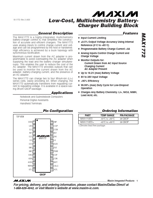
General DescriptionThe MAX1772 is a highly-integrated, multichemistry battery-charger control IC that simplifies the construc-tion of accurate and efficient chargers. The MAX1772uses analog inputs to control charge current and volt-age and can be programmed by the host or hardwired.High efficiency is achieved by a buck topology with synchronous rectification.Maximum current drawn from the AC adapter is pro-grammable to avoid overloading the AC adapter when supplying the load and the battery charger simultane-ously. This enables the user to reduce the cost of the AC adapter. The MAX1772 provides outputs that can be used to monitor the current drawn from the AC adapter, battery-charging current, and the presence of an AC adapter.The MAX1772 can charge two to four lithium-ion (Li+)series cells, easily providing 4A. When charging, the MAX1772 automatically transitions from regulating cur-rent to regulating voltage. It is available in a space-sav-ing 28-pin QSOP package.ApplicationsNotebook and Subnotebook Computers Personal Digital Assistants Handheld TerminalsFeatures♦Input Current Limiting♦±0.5% Output Voltage Accuracy Using Internal Reference (0°C to +85°C)♦Programmable Battery Charge Current >4A ♦Analog Inputs Control Charge Current and Charge Voltage ♦Monitor Outputs for:Current Drawn from AC Input Source Charging Current AC Adapter Present ♦Up to 18.2V (max) Battery Voltage ♦8V to 28V Input Voltage ♦>95% Efficiency♦99.99% (max) Duty Cycle for Low-Dropout Operation ♦Charges Any Battery Chemistry: Li+, NiCd, NiMH,Lead Acid, etc.MAX1772Low-Cost, Multichemistry Battery-Charger Building Block________________________________________________________________Maxim Integrated Products1Pin Configuration19-1772; Rev 3; 8/05Ordering InformationFor pricing, delivery, and ordering information,please contact Maxim/Dallas Direct!at1-888-629-4642, or visit Maxim’s website at .+Denotes lead-free package.M A X 1772Low-Cost, Multichemistry Battery-Charger Building BlockABSOLUTE MAXIMUM RATINGSELECTRICAL CHARACTERISTICS(V DCIN = V CSSP = V CSSN = 18V, V BATT = V CSIP = V CSIN = 12V, V REFIN = 3.0V, V VCTL = V ICTL = 0.75 ✕REFIN, CELLS = 2.0V,Stresses beyond those listed under “Absolute Maximum Ratings” may cause permanent damage to the device. These are stress ratings only, and functional operation of the device at these or any other conditions beyond those indicated in the operational sections of the specifications is not implied. Exposure to absolute maximum rating conditions for extended periods may affect device reliability.DCIN, CSSP, CSSN to GND...................................-0.3V to +30V BST to GND............................................................-0.3V to +36V BST to LX..................................................................-0.3V to +6V DHI to LX....................................................-0.3V to (BST + 0.3V)LX to GND .................................................................-6V to +30V BATT, CSIP, CSIN to GND........................................-0.3V to 20V CSIP to CSIN or CSSP to CSSN orPGND to GND ...........……….……………..…….-0.3V to +0.3V CCI, CCS, CCV, DLO, ICHG, IINP,ACIN, REF to GND ..............................-0.3V to (VLDO + 0.3V)DLOV, VCTL, ICTL, REFIN, CELLS,CLS, LDO, ACOK to GND....................................-0.3V to +6VDLOV to LDO.........................................................-0.3V to +0.3V DLO to PGND..........................................-0.3V to (DLOV + 0.3V)LDO Short-Circuit Current ..................................................50mA Continuous Power Dissipation (T A = +70°C)28-Pin QSOP (derate 10.8mW/°C above +70°C).........860mW Operating Temperature RangeMAX1772EEI....................................................-40°C to +85°C Junction Temperature........................................................150°C Storage Temperature Range.............................-60°C to +150°C Lead Temperature (soldering, 10s).................................+300°CMAX1772Low-Cost, Multichemistry Battery-Charger Building Block_______________________________________________________________________________________3ELECTRICAL CHARACTERISTICS (continued)(V DCIN = V CSSP = V CSSN = 18V, V BATT = V CSIP = V CSIN = 12V, V REFIN = 3.0V, V VCTL = V ICTL = 0.75 ✕REFIN, CELLS = 2.0V,ACIN = 0, CLS = REF, V- V = 4.5V, GND = PGND = 0, C = 1µF, LDO = DLOV, C = 1µF; pins CCI, CCS, and CCV areM A X 1772Low-Cost, Multichemistry Battery-Charger Building Block 4_______________________________________________________________________________________ELECTRICAL CHARACTERISTICS (continued)(V DCIN = V CSSP = V CSSN = 18V, V BATT = V CSIP = V CSIN = 12V, V REFIN = 3.0V, V VCTL = V ICTL = 0.75 ✕REFIN, CELLS = 2.0V,ACIN = 0, CLS = REF, V BST - V LX = 4.5V, GND = PGND = 0, C LDO = 1µF, LDO = DLOV, C REF = 1µF; pins CCI, CCS, and CCV areMAX1772Low-Cost, Multichemistry Battery-Charger Building Block_______________________________________________________________________________________5ELECTRICAL CHARACTERISTICS(V DCIN = V CSSP = V CSSN = 18V, V BATT = V CSIP = V CSIN = 12V, V REFIN = 3.0V, V VCTL = V ICTL = 0.75 ✕REFIN, CELLS = 2.0V,ACIN = 0, CLS = REF, V BST - V LX = 4.5V, GND = PGND = 0, C LDO = 1µF, LDO = DLOV, C REF = 1µF; pins CCI, CCS, and CCV are compensated per Figure 1a; T= -40°C to +85°C,unless otherwise noted.) (Note 1)M A X 1772Low-Cost, Multichemistry Battery-Charger Building Block 6_______________________________________________________________________________________ELECTRICAL CHARACTERISTICS (continued)(V DCIN = V CSSP = V CSSN = 18V, V BATT = V CSIP = V CSIN = 12V, V REFIN = 3.0V, V VCTL = V ICTL = 0.75 ✕REFIN, CELLS = 2.0V,ACIN = 0, CLS = REF, V BST - V LX = 4.5V, GND = PGND = 0, C LDO = 1µF, LDO = DLOV, C REF = 1µF; pins CCI, CCS, and CCV are compensated per Figure 1a; T A = -40°C to +85°C,unless otherwise noted.) (Note 1)Note 2:Tested under DC conditions. See text for more detail.MAX1772Low-Cost, Multichemistry Battery-Charger Building Block_______________________________________________________________________________________7Typical Operating Characteristics(Circuit of Figure 1a, V DCIN = 20V, T A = +25°C, unless otherwise noted.)V BATT 20V/div I BATT 2A/divCCI500mV/div CCV 500mV/divLOAD-TRANSIENT RESPONSE(BATTERY REMOVAL AND REINSERTION)MAX1772 toc011ms/divICTL = 0.957V VCTL = 3.3VCCICCV V BATT 20V/div I LOAD 2A/divCCS 500mV/div CCI500mV/div LOAD-TRANSIENT RESPONSE (STEP-IN LOAD CURRENT)1ms/divICTL = 3.30VCHARGING CURRENT = 2.0A V BATT = 16VLOAD STEP = 0 TO 3A I SOURCE LIMIT = 5ACCI CCSV BATT(AC-COUPLED)100mV/divDCIN 10V/divLINE-TRANSIENT RESPONSEMAX1772 toc032ms/divV BATT = 16VDCIN = 18.5V TO 27.5V I LOAD = 150mA-0.4-0.2-0.3-0.10.20.30.100.4023*********LDO LOAD REGULATIONLDO CURRENT (mA)L D O E R R O R (%)M A X 1772Low-Cost, Multichemistry Battery-Charger Building Block 8_______________________________________________________________________________________-0.5-0.2-0.3-0.4-0.100.10.20.30.40.5-4010-15356085REF VOLTAGE ERROR vs. TEMPERATURETEMPERATURE (°C)R E F V O L T A G E E R R O R (%)10000.1110100100010,000EFFICIENCY vs. BATTERY CURRENT(VOLTAGE CONTROL LOOP)20BATT CURRENT (mA)E F F I C I E N C Y (%)4060801030507090100100100010,000EFFICIENCY vs. BATTERY CURRENT(CURRENT CONTROL LOOP)20E F F I C I E N C Y (%)4060801030507090BATT CURRENT (mA)Typical Operating Characteristics (continued)(Circuit of Figure 1a, V DCIN = 20V, T A = +25°C, unless otherwise noted.)-1.0-0.6-0.8-0.2-0.40.200.40.80.61.081620122428LDO LINE REGULATIONDCIN (V)L D O E R R O R (%)-0.20-0.10-0.15-0.050.100.150.0500.20010015020025050300350400450500REF VOLTAGE LOAD REGULATIONREF CURRENT (μA)R E F E R R O R (%)MAX1772Low-Cost, Multichemistry Battery-Charger Building Block_______________________________________________________________________________________9Typical Operating Characteristics (continued)(Circuit of Figure 1a, V DCIN = 20V, T A = +25°C, unless otherwise noted.)00.0100.0050.0200.0150.0300.0250.0350.0450.0400.05001000150050020002500300035004000OUTPUT V/I CHARACTERISTICSBATT CURRENT (mA)B A T T V O L T A G E E R R O R (%)00.040.020.080.060.120.100.140.180.160.200.20.30.40.10.50.60.70.90.8 1.0BATT VOLTAGE ERROR vs. VCTLVCTL/REFIN (%)B A T T V O L T A G E E R R O R (%)0124350.40.20.60.80.10.50.30.70.9 1.0CURRENT SETTING ERROR vs. ICTLICTL/REFIN (%)C U R R E N T S E T T I N G E R R O R (%)00.51.51.02.52.03.53.04.01000150050020002500300035004000ICHG ERROR vs. BATT LOAD CURRENTBATT LOAD CURRENT (mA)I C H G E R R O R (%)M A X 1772Low-Cost, Multichemistry Battery-Charger Building Block 10______________________________________________________________________________________MAX1772Charger Building Block______________________________________________________________________________________11Detailed DescriptionThe MAX1772 includes all of the functions necessary to charge Li+, NiMH, and NiCd batteries. A high-efficiency synchronous-rectified step-down DC-DC converter con-trols charging voltage and current.It also includes input source-current limiting and analog inputs for setting the charge current and charge voltage. The DC-DC con-verter uses external N-channel MOSFETs as the buck switch and synchronous rectifier to convert the input voltage to the required charging current and voltage.The typical application circuit shown in Figure 1a uses a microcontroller (µC) to allow control of charging cur-rent or voltage, while Figure 1b shows a typical appli-cation with charging voltage and current fixed to specific values for the application. The voltage at ICTL and the value of RS2 set the charging current. The DC-DC converter generates the control signals for the external MOSFETs to regulate the voltage and the cur-rent set by the VCTL, ICTL, and CELLS inputs.The MAX1772 features a voltage-regulation loop (CCV)and two current-regulation loops (CCI and CCS). The CCV voltage-regulation loop monitors BATT to ensure that its voltage never exceeds the voltage set by VCTL.The CCI battery current-regulation loop monitors cur-rent delivered to BATT to ensure that it never exceeds the current limit set by ICTL. A third loop (CCS) takes control and reduces the battery-charging current when the sum of the system load and the battery-charging current exceeds the charging source current limit set by CLS.Setting the Battery Regulation VoltageThe MAX1772 uses a high-accuracy voltage regulator for charging voltage. The VCTL input adjusts the bat-tery output voltage. VCTL is allowed to vary from 0 to REFIN (≈ 3.3V). The per-cell battery termination voltage is a function of the battery chemistry and construction;thus, consult the battery manufacturer to determine this voltage. The battery voltage is calculated by the equa-tion:CELLS is the programming input for selecting cell count. Table 1 shows how CELLS is connected to charge 2, 3, or 4 cells. Use a voltage-divider from LDO to set the desired voltage at CELLS.The internal error amplifier (G MV) maintains voltage regulation (Figure 2). The voltage error amplifier is com-pensated at CCV. The component values shown in Figure 1 provide suitable performance for most appli-cations. Individual compensation of the voltage regula-tion and current-regulation loops allow for optimal com-pensation.Setting the Charging-Current LimitThe ICTL input sets the maximum charging current. The current is set by current-sense resistor RS2, connected between CSIP and CSIN. The nominal differential volt-age between CSIP and CSIN is 204mV; thus, for a 0.05Ωsense resistor, the maximum charging current is 4A. Battery-charging current is programmed with ICTL using the equation:The input range for ICTL is REFIN/32 to REFIN (≈ 3.3V).The device shuts down if ICTL is forced below REFIN/55 (typical). The current at ICHG is a scaled-down replica of the battery output current being sensed across CSIP and CSIN.When choosing the current-sense resistor, note that the voltage drop across this resistor causes further power loss, reducing efficiency. However, adjusting ICTL to reduce the voltage across the current-sense resistor may degrade accuracy due to the input offset of the current-sense amplifier. The charging current-error amplifier (G MI) is compensated at CCI. A 0.01µF capacitor at CCI provides suitable performance for most applications.Setting the Input Current LimitThe total input current (from a wall cube or other DCsource) is a function of the system supply current and the battery-charging current. The input current regula-tor limits the source current by reducing the charging current when the input current exceeds the set input current limit. System current will normally fluctuate as portions of the system are powered up or put to sleep.Without input current regulation, the input source must be able to supply the maximum system current and the maximum charger input current. By using the input cur-rent limiter, the current capability of the AC wall adapter may be lowered, reducing system cost.The MAX1772 limits the current drawn by the charger when the load current becomes high. The device limits the charging current, so the AC adapter voltage is not loaded down. An internal amplifier compares the volt-age between CSSP and CSSN to the voltage at CLS.V CLS can be set by a resistor-divider between REF and G ND. Connect CLS to REF for maximum input currentlimiting.V ELLS V V VV 1BATT REF REF VCTL REFIN =×+×⎛⎝⎜⎞⎠⎟⎛⎝⎜⎞⎠⎟()C 10M A X 1772Charger Building Block 12______________________________________________________________________________________Figure 1a. µC-Controlled Typical Application CircuitMAX1772Charger Building Block______________________________________________________________________________________13Figure 1b. Stand-Alone Typical Application CircuitM A X 1772Charger Building Block 14______________________________________________________________________________________Figure 2. Functional DiagramMAX1772Charger Building Block______________________________________________________________________________________15The input source current is the sum of the device cur-rent, the charger input current, and the load current.The device current is minimal (6mA) in comparison to the charge and load currents. The actual source cur-rent required is determined as follows:where ηis the efficiency of the DC-DC converter (85%to 95% typ).V CLS determines the reference voltage of the G MS error amplifier. Sense resistor RS1 sets the maximum allowable source current. Calculate the maximum cur-rent as follows:Once the input current limit is reached, the charging current is tapered back until the input current is below the desired threshold.When choosing the current-sense resistor, note that the voltage drop across this resistor causes further power loss, reducing efficiency.AC Adapter DetectionConnect the AC adapter voltage through a resistive divider to ACIN to detect when AC power is available,as shown in Figure 1. ACOK is an open-drain output and is high when ACIN is less than REF/2.Current MeasurementUse ICHG to monitor the battery-charging current being sensed across CSIP and CSIN. The output volt-age range is 0 to 3V. The voltage of ICHG is proportion-al to the output current by the equation:where I CHG is the battery-charging current, G ICHG is the transconductance of ICHG (1mS typ), and R9 is the resistor connected between ICHG and ground.Connect ICHG pin to ground if it is not used.Use IINP to monitor the system input current being sensed across CSSP and CSSN. The output voltage range is 0 to 3V. The voltage of IINP is proportional to the output current by the equation:where I SOURCE is the DC current being supplied by the AC adapter power, G IINP is the transconductance of IINP (1mS typ), and R10 is the resistor connected between IINP and ground.In the typical application circuit, duty cycle affects the accuracy of V IINP (Figure 3). AC load current also affects accuracy (Figure 4).Connect IINP pin to ground if it is not used.LDO RegulatorLDO provides a 5.4V supply derived from DCIN and can deliver up to 15mA of current. The MOSFET drivers are powered by DLOV and BST, which must be con-nected to LDO as shown in Figure 1. LDO also supplies the 4.096V reference (REF) and most of the control cir-cuitry. Bypass LDO with a 1µF capacitor.DC-to-DC ConverterThe MAX1772 employs a buck regulator with a boot-strapped NMOS high-side switch and a low-side NMOS synchronous rectifier.DC-DC ControllerThe control scheme is a constant off-time variable fre-quency, cycle-by-cycle current mode. The off-time is constant for a given BATT voltage. It varies with V BATT operation; a maximum on-time of 10ms allows the con-troller to achieve >99% duty cycle with continuous con-duction. Figure 5 shows the controller functional diagram.MOSFET DriversThe low-side driver output DLO swings from 0 to DLOV.DLOV is usually connected through a filter to LDO. The high-side driver output DHI is bootstrapped off LX and swings from V LX to V BST . When the low-side driver turns on, BST rises to one diode voltage below DLOV.Filter DLOV with a resistor-capacitor (RC) circuit whose cutoff frequency is about 50kHz. The configuration in Figure 1 introduces a cutoff frequency of around 48kHz:f = 1/2πRC = 1 / (2π✕33Ω✕0.1µF) = 48kHz(7)V IINP SOURCE IINP =×××()I RS G R 1106V 9ICHG CHG ICHG =×××()I RS G R 25I SOURCE_MAX CLS =×()()V RS /2014I I I 3SOURCE LOAD CHARGE BATT IN =+×()×()[]()V V /ηM A X 1772Charger Building Block 16______________________________________________________________________________________Dropout OperationThe MAX1772 has 99.99% duty-cycle capability with a 10ms maximum on-time and 1µs off-time. This allows the charger to achieve dropout performance limited only by resistive losses in the DC-DC converter compo-nents (D1, N1, RS1, RS2) (Figure 1). The actual dropout voltage is limited to 100mV between CSSP and CSIN by the power-fail comparator.CompensationEach of the three regulation loops—the input current limit, the charging current limit, and charging voltage limit—can be compensated separately using the CCS,CCI, and CCV pins, respectively.The charge-current-loop error-amp output is brought out at CCI. Likewise, the source current error-amp out-put is brought out at CCS; 0.01µF capacitors to ground at CCI and CCS compensate the current loops in most charger designs. Raising the value of these capacitors reduces the bandwidth of these loops.The voltage-regulating-loop error-amp output is brought out at CCV. Compensate this loop by connecting a series RC network from CCV to G ND. Recommended values are 1k Ωand 0.1µF. The zero set by the series RC increases midfrequency gain to provide phase compensation. The pole at CCV is set by the capacitor and the voltage error-amp output impedance at low fre-quencies to integrate the DC error.Component SelectionTable 2 lists the recommended components and refers to the circuit of Figure 1. The following sections describe how to select these components.MOSFETs and Schottky DiodesSchottky diode D1 provides power to the load when the AC adapter is inserted. This diode must be able to deliver the maximum current as set by RS1.The N-channel MOSFETs (N1, N2) are the switching devices for the buck controller. High-side switch N1should have a current rating of at least 8A and have an on-resistance (R DS(ON)) of 50m Ωor less. The driver for N1 is powered by BST; its current should be less than 10mA. Select a MOSFET with a low total gate charge (Q GATE ) and determine the required drive current by I GATE = Q GATE ✕f (where f is the DC-DC converter’s 400kHz maximum switching frequency).The low-side switch (N2) should also have a current rat-ing of at least 8A, have an R DS(ON)of 100m Ωor less,and a total gate charge less than 10nC. N2 is used to provide the starting charge to the BST capacitor (C15).During normal operation, the current is carried by Schottky diode D2. Choose a Schottky diode capable of carrying the maximum charging current.D3 is a signal-level diode, such as the 1N4148. This diode provides the supply current to the high-side MOSFET driver.Inductor SelectionInductor L1 provides power to the battery while it is being charged. It must have a saturation current of at least 4A plus 1/2 of the current ripple (ΔI L ):I SAT = 4A + (1/2) ΔI L(8)Figure 3. IINP Accuracy vs. V DCIN /V BATTFigure 4. IINP Accuracy vs. AC Load Duty CycleMAX1772Charger Building Block______________________________________________________________________________________17Figure 5. DC-to-DC Converter Functional DiagramM A X 1772Charger Building Block 18______________________________________________________________________________________The controller determines the constant off-time period,which is dependent on BATT voltage. This makes the ripple current independent of input and battery voltage,and it should be kept to less than 1A. Calculate ΔI L with the following equation:(9)Higher inductor values decrease the ripple current.Smaller inductor values require high saturation current capabilities and degrade efficiency. Typically, a 22µH inductor is ideal for all operating conditions.Current-Sense Input FilteringIn normal circuit operation with typical components, the current-sense signals can have high-frequency tran-sients that exceed 0.5V due to large current changes and parasitic component inductance. To achieve prop-er battery and input current compliance, the current-sense input signals should be filtered to remove large common-mode transients. The input current-limit sens-ing circuitry is the most sensitive case due to large cur-rent steps in the input filter capacitors (C6, C7) in Figure 1. Use 0.47µF ceramic capacitors from CSSP and CSSN to ground. Smaller 0.1µF ceramic capacitors (C18, C19) can be used on the CSIP and CSIN inputs to ground since the current into the battery is continu-ous. Place these capacitors next to the single-point ground directly under the MAX1772.Layout and BypassingBypass DCIN with a 1µF to ground (Figure 1). D4 pro-tects the MAX1772 when the DC power source input is reversed. A signal diode for D4 is adequate because DCIN only powers the LDO and the internal reference.Bypass LDO, BST, DLOV, and other pins as shown in Figure 1.G ood PC board layout is required to achieve specified noise, efficiency, and stable performance. The PC board layout artist must be given explicit instructions—prefer-ably, a pencil sketch showing the placement of the power switching components and high current routing.Refer to the PC board layout in the MAX1772 evaluation kit for examples. A ground plane is essential for optimum performance. In most applications, the circuit will be located on a multilayer board, and full use of the four or more copper layers is recommended. Use the top layer for high current connections, the bottom layer for quiet connections (REF, CCV, CCI, CCS, DCIN, and G ND),and the inner layers for an uninterrupted ground plane.Use the following step-by-step guide:1)Place the high power connections first, with theirgrounds adjacent:•Minimize the current-sense resistor tracelengths, and ensure accurate current sensing with Kelvin connections.•Minimize ground trace lengths in the high current paths.•Minimize other trace lengths in the high current paths.•Use >5mm wide traces.•Connect C1 and C2 to high-side MOSFET (10mm max length).•LX node (MOSFETs, rectifier cathode, inductor (15mm max length)).Ideally, surface-mount power components are flush against one another with their ground terminals almost touching. These high-current grounds are then connected to each other with a wide, filled zone of top-layer copper, so they do not go through vias.The resulting top-layer subground plane is connect-ed to the normal inner-layer ground plane at the output ground terminals, which ensures that the IC’s analog ground is sensing at the supply’s output terminals without interference from IR drops and ground noise. Other high current paths should also be minimized, but focusing primarily on short ground and current-sense connections eliminates about 90% of all PC board layout problems.2)Place the IC and signal components. Keep themain switching node (LX node) away from sensitive analog components (current-sense traces and REF capacitor). Important: the IC must be no further than 10mm from the current-sense resistors.Keep the gate drive traces (DHI, DLO, and BST)shorter than 20mm, and route them away from the current-sense lines and REF. Place ceramic bypass capacitors close to the IC. The bulk capacitors can be placed further away. Place the current-sense input filter capacitors under the part, connected directly to the GND pin.3)Use a single-point star ground placed directlybelow the part. Connect the input ground trace,power ground (subground plane), and normalground to this node.MAX1772Charger Building Block______________________________________________________________________________________19Chip InformationTRANSISTOR COUNT: 2733PROCESS: S12M A X 1772Charger Building Block Maxim cannot assume responsib ility for use of any circuitry other than circuitry entirely emb odied in a Maxim product. No circuit patent licenses are implied. Maxim reserves the right to change the circuitry and specifications without notice at any time.20____________________Maxim Integrated Products, 120 San Gabriel Drive, Sunnyvale, CA 94086 408-737-7600©2005 Maxim Integrated ProductsPrinted USAis a registered trademark of Maxim Integrated Products, Inc.Package Information(The package drawing(s) in this data sheet may not reflect the most current specifications. For the latest package outline information,go to /packages .)。
电动汽车充电国际标准一览

∆ DC
∆AC L3:TBD
◦ 200 – 600V DC ? ◦ Rated Current ≤ 400 amp? ◦ Rated Power ≤ 240kw?
Voltages are nominal configuration operating voltages, not coupler rating. Rated power is at nominal configuration operating voltage and coupler rated current.
standardsupdateglobalapproachesvehiclegridconnectivitygerykisselsaej1772taskforcechairsaej1772委员会主席generalmotorsengineeringspecialist通用汽车电动汽车工程专家august302010electricvehiclecharginginternationalstandardsstatus电动汽车充电国际标准一览iec621962saej1772dcchargestandardsharmonizationopportunities交流及直流充电标准协调的机privatevehiclecharginginfrastructure私人电动车充电设施publiccharging公共充电highvisibility标识醒目commercialretail商业区零售店workplace工作场所corporatemunicipalparkinglots公司单位的停车场residentialmajority住宅区主体satisfyingconsumerdrivenhomeinstallationprocess满足消费者家用安装流程方便安全includessinglemultiplefamilyhomesapartmentsremotechargelocations单个及多个家庭公寓和附近的充电站permitselectriciansinspectionsmetersrates安装许可电工资质认可安全质检计量仪表收费publicresidentialworkplacechargingstandardssummarychargestandardssummaryacchinausjapaneusinglephasetypej1772j1772j1772type1phasetypetype2allmodesphasetypetype3allmodesdc200a350a400amodej1772hybridtepcotypesaechargingconfigurationsratingsterminologyacl1
Wikipedia-SAE J1772
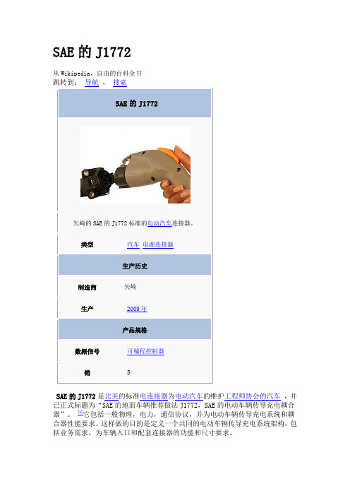
SAE的J1772从Wikipedia,自由的百科全书SAE的J1772是北美的标准电连接器为电动汽车的维护工程师协会的汽车,并已正式标题为“SAE的地面车辆推荐做法J1772,SAE的电动车辆传导充电耦合器”。
[1]它包括一般物理,电力,通信协议,并为电动车辆传导充电系统和耦合器性能要求。
这样做的目的是定义一个共同的电动车辆传导充电系统架构,包括业务需求,为车辆入口和配套连接器的功能和尺寸要求。
AVCON公司生产的矩形连接器电源符合的SAE J1772规范修订版2001年11月,电是能够提供高达6.6千瓦的。
[2]当前的SAE J1772修订(截至2009年10月),非正式名称为SAE的J1772 - 2009,是基于一个由圆形连接器设计矢崎和相位允许最多单增加功率16.8千瓦交付通过交付120-240 V 交流高达70安培。
[ 来源请求 ]内容[hide]∙ 1 发展∙ 2 通过∙3个属性o 3.1 连接器o 3.2 充电o 3.3 安全o 3.4 信号[6]∙ 4 兼容的车型∙ 5 兼容充电站∙ 6 竞争的标准∙7 参考资料∙8 外部链接发展在矢崎插头被修造的SAE J1772标准插头认证成功地完成了UL认证。
它是唯一认证为30A虽然标准被写入至80A有一个在图片的矢崎插头TEVA2,其中烫印只显示30A条。
标准规范是经表决后的SAE委员会2009年7月。
[3]通过SAE的J1772通过了2010年1月14日通过的SAE汽车会。
[4]本公司参与或支持修订后的-2009标准包括通用,克莱斯勒,福特,丰田,本田,日产和特斯拉。
性能连接该连接器的设计与120 V或240 V,如北美和日本使用的单相电力系统。
43毫米直径的圆形连接器有五针,针3种不同尺寸。
[5]∙ 1号线和AC交流2号线 - 电源引脚具有相同的大小∙接地引脚∙就近性检测和控制试点 - 具有相同大小的针就近性检测 - 防止汽车的运动,同时连接到充电器。
新能源汽车电气技术(第2版)课件:新能源汽车充电系统

三、充电系统基本术语
1.交流充电(AC charging) 指通过交流电对带充电系统的新源汽车的动 力蓄电池组充电。进行交流充电时,车辆的车 载充电器必须将交流电整流成直流电,并调节 充电电压,使其符合动力蓄电池组的要求。
三、充电系统基本术语
2.直流充电(DC charging) 指通过直流电对带充电系统的新能源汽车的动 力蓄电池组充电。进行直流充电时,直流电被 输送到动力蓄电池组,由充电站来调整动力蓄 电池组的充电电压。
八、DC/DC变换器的类型
目前在新能源汽车里DC/DC变换器有三种类型: 1.高低压转换器(辅助功率模块) 此模块主要作用是取代传统燃油汽车的12V发电机,在混和动力车辆里,发动机 输出的动力直接驱动高压继电器直接给电池系统补充电力,传统的12V的用电负荷就 完全依靠DC/DC供给,功率范围可以从1KW-2.2KW。 2.12V电压稳定器 这个12V电压稳定器,主要用在部分启停start-stop系统,在启动中避免电压波 动对一些敏感的负载造成影响或损坏,例如用户可见的负载,车内照明等,收音机和 显示屏等,电压稳压器的功率等级随着用电器负荷而定,一般是200-400W。 3.高压升压器 为了提高动力系统的效率,选用一个升压器来提高逆变输入的电压,这个部件是 动力总成的一部分,集成在动力总成中。如果采用锂离子蓄电池作为动力蓄电池,升 压器是一个十分重要的部分。
四、常用充电方法
2.恒流充电方式 恒流充电方式也是人们常采用的方法。一开始充电系统以一定的恒定的电流为蓄电池充电, 该电流保持在电池可接受的范围内,当控制系统检测将要充满时,改用恒定的小电流为其充电, 进入所谓的浮充阶段,浮充的作用是用来充足剩余的电量和补偿电池的自放电,当充电电压达到 电池的额定电压时,停止充电。该种充电方式避免了恒压充电电流过大的问题,电流始终被限制 在电池组可接受的范围内,但由于电流始终恒定,无形中延长了充电所需的时间。
SAE J1772-2001 SAE Electric Vehicle Conductive Charge Coupler
SAE Technical Standards Board Rules provide that: “This report is published by SAE to advance the state of technical and engineering sciences. The use of this report is entirely voluntary, and its applicability and suitability for any particular use, including any patent infringement arising therefrom, is the sole responsibility of the user.”SAE reviews each technical report at least every five years at which time it may be reaffirmed, revised, or cancelled. SAE invites your written comments and suggestions.TO PLACE A DOCUMENT ORDER: +1 (724) 776-4970 FAX: +1 (724) 776-0790SAE WEB ADDRESS Copyright 2001 Society of Automotive Engineers, Inc.1.Scope—This SAE Recommended Practice covers the general physical, electrical, and performancerequirements for the electric vehicle conductive charge system and coupler for use in North America. The intent of this document is to define a common electric vehicle conductive charging system architecture including operational requirements and the functional and dimensional requirements for the vehicle inlet and mating connector.2.References2.1Applicable Publications—The following publications form a part of this specification to the extent specifiedherein. Unless otherwise indicated, the latest issue of SAE and other applicable publications shall apply.2.1.1SAE P UBLICATIO NS—Available from SAE, 400 Commonwealth Drive, Warrendale, PA 15096-0001.SAEJ551-5—Performance Levels and Methods of Measurement of Electromagnetic Radiation from Vehicles and Devices (30 Hz to 1000 MHz)SAE J551-11—Vehicle Electromagnetic Immunity—Off-Vehicle SourceSAE J551-15—Vehicle Electromagnetic Immunity—Electrostatic Discharge (ESD)SAE J1211—Recommended Environmental Practices for Electronic Equipment DesignSAE J1850—Class B Data Communication Network MessagesSAE J2178—Class B Data communication Network Messages – Network Management StrategiesSAE J2293—Energy Transfer System for Electric Vehicle2.1.2C ANA DIAN S TANDARDS A SSOCIATION—Available from Canadian Standards Association, 170 RexdaleBoulevard, Rexdale, Ontario, Canada M9W 1R3.Canadian Electrical Code—Part 1, Section 862.1.3F EDERAL C OMMUNICATION C OMMISSIO N P UBLICATIONS—Available from The Superintendent of Documents, U.S. Government Printing Office, Mail Stop SSOP, Washington, D.C. 20402-9320.CFR 40 - Code of Federal Regulations—Title 40, Part 600, Subchapter QCFR 47- Code of Federal Regulations—Title 47, Parts 15A, 15B, and 18C2.1.4I NTERNA TIONAL E LECTROTECHNICAL C OMMISSION P UBLICATIO N—Available from the InternationalElectrotechnical Commission, 3, Rue de Varembe / CH-1211, Geneva 20, Switzerland.NOTE—IEC Publications are also available from The American National Standards Institute, 25 West 43rd Street, New York, NY 10036-8002.IEC 61851-2.1—Electric Vehicle Conductive Charging System—Part 2.1: Electric Vehicle Requirements for Connection to an AC / DC supply2.1.5N ATIO NAL F IRE P ROTECTIO N A SSOCIATION P UBLICATION—Available from The National Fire ProtectionAssociation, Batterymarch Park, Quincy, MA 02269.National Electrical Code, NFPA 70—Article 6252.1.6U NDERWRITERS L ABO RATORIES, I NC. P UBLICATIONS—Available from Underwriters Laboratories, Inc.,Corporate offices, 333 Pfingsten Road, Northbrook, IL 60062-2096. Phone (708)272-8800.UL 50—Standard for Enclosures for Electrical EquipmentUL 1439—Determination of Sharpness of Edges on EquipmentUL 2202—EV Charging System EquipmentUL 2231—Personnel Protection Systems for EV Charging CircuitsUL 2251—Plugs, Receptacles, and Couplers for Electric Vehicles2.2Related Publications—The following publications are provide for information purposes only and are not arequired part of this document2.2.1SAE P UBLICATIO NS—Available from SAE, 400 Commonwealth Drive, Warrendale, PA 15096SAE J1742—Connections for High Voltage On-board Vehicle Electrical Wiring HarnessSAE J1773—SAE Electric Vehicle Inductively Coupled Charging2.2.2I NTERNA TIONAL E LECTROTECHNICAL C OMMISSION P UBLICATIO NS—Available from the InternationalElectrotechnical Commission, 3, Rue de Varembe / CH-1211, Geneva 20, SwitzerlandNOTE—IEC Publications are also available from The American National Standards Institute, 25 West 43rd Street, New York, NY 10036-8002IEC 61851-1—Electric Vehicle Conductive Charging System—Part 1: General RequirementsIEC61851-2.2—Electric Vehicle Conductive Charging System—Part 2.2: AC electric vehicle charging stationIEC61851-2.3—Electric Vehicle Conductive Charging System—Part 2.3: DC electric vehicle charging station2.2.3U NDERWRITERS L ABO RATORIES, I NC. P UBLICATIONS—Available from Underwriters Laboratories, Inc.,Corporate offices, 333 Pfingsten Road, Northbrook, IL 60062-2096. Phone (708)272-8800UL 94—Tests for Flammability of Plastic Materials for Parts in Devices and AppliancesUL 746A—Standard for Polymeric Materials – Short Term Property EvaluationsUL 840—Insulation Coordination including Clearance and Creepage Distances for Electrical Equipment 3.Definitions3.1Charger—An electrical device that converts alternating current energy to regulated direct current forreplenishing the energy of an energy storage device (i.e., battery) and may also provide energy for operating other vehicle electrical systems.3.2Conductive—Having the ability to transmit electricity through a physical path (conductor).3.3Connector—A conductive device that by insertion into a vehicle inlet establishes an electrical connection tothe electric vehicle for the purpose of transferring energy and exchanging information. This is part of the coupler.3.4Coupler—A mating vehicle inlet and connector set.3.5Electric vehicle (EV)—An automotive type vehicle, intended for highway use, primarily powered by an electricmotor that draws from a rechargeable energy storage device. For the purpose of this document the definition in the United States Code of Federal Regulations — Title 40, Part 600, Subchapter Q is used. Specifically, an automobile means:a.Any four wheeled vehicle propelled by a combustion engine using on-board fuel or by an electric motordrawing current from a rechargeable storage battery or other portable energy devices (rechargeableusing energy from a source off the vehicle such as residential electric service).b.Which is manufactured primarily for use on public streets, roads, and highways.c.Which is rated not more that 3855.6 kg (8500 lb), which has a curb weight of not more than 2721.6 kg(6000lb), and which has a basic frontal area of not more than 4.18 m2 (45 ft2).3.6Enclosure—The case or housing into which the contacts and insulators are assembled.3.7Insulator—The portion of a coupler that provides for the separation, support, sealing, and protection of thecontacts.3.8Contact—A conductive element in a connector that mates with a corresponding element in the vehicle inlet toprovide an electrical path.3.9AC Level 1 Charging—A method that allows an EV to be connected to the most common grounded electricalreceptacle (NEMA 5-15R). The vehicle shall be fitted with an on-board charger capable of accepting energy from the existing alternating current (AC) supply network. The maximum power supplied for AC Level 1 charging shall conform to the values in Table 1.3.10AC Level 2 Charging—A method that utilizes dedicated AC. EV supply equipment in either private or publiclocations. The vehicle shall be fitted with an on-board charger capable of accepting energy from alternating current electric vehicle supply equipment. The maximum power supplied for AC Level 2 charging shall conform to the values in Table 1.3.11DC Charging—A method that utilizes dedicated direct current (DC) EV supply equipment to provide energyfrom an appropriate off-board charger to the EV in either private or public locations. The range of charger ratings encompassed shall conform to the values shown in Table 1.3.12Off-Board Charger—A charger located off of the vehicle.3.13On-Board Charger—A charger located on the vehicle.3.14Equipment Ground (Grounding Conductor)—A conductor used to connect the non-current carrying metalparts of the EV supply equipment to the system grounding conductor, the grounding electrode conductor, or both at the service equipment.3.15Chassis Ground—The conductor used to connect the non-current carrying metal parts of the vehicle highvoltage system to the equipment ground.3.16Control Pilot—The primary control conductor that is connected to the equipment ground through controlcircuitry on the vehicle and performs the following functions:a.Verifies that the vehicle is present and connectedb.Permits energization/de-energization of the supplyc.Transmits supply equipment current rating to the vehicled.Monitors the presence of the equipment grounde.Establishes vehicle ventilation requirements3.17Vehicle Inlet—The device on the electric vehicle into which the connector is inserted for the purpose oftransferring energy and exchanging information. This is part of the coupler.3.18Electric Vehicle Supply Equipment (EVSE)—The conductors, including the ungrounded, grounded, andequipment grounding conductors, the electric vehicle connectors, attachment plugs, and all other fittings,devices, power outlets, or apparatuses installed specifically for the purpose of delivering energy from the premises wiring to the electric vehicle.3.19 3.19 EV Charging System—The equipment required to condition and transfer energy from the constantfrequency, constant voltage supply network to the direct current, variable voltage EV traction battery bus for the purpose of charging the battery and/or operating vehicle electrical systems while connected.4.General Conductive Charging System Description—In the most fundamental sense, there are 3 functions,2 electrical and 1 mechanical, that must be performed to allow charging of the EV battery from the electric supply network. The electric supply network transmits alternating current electrical energy at various nominal voltages(rms) and a frequency of 60 Hz. The EV battery is a direct current device that operates at a varying voltage depending on the nominal battery voltage, state-of-charge, and charge/discharge rate. The first electrical function converts the alternating current to direct current and is commonly referred to as rectification.The second electrical function is the supply voltage must be controlled or regulated at a voltage level that permits a managed charge rate based on the battery charge acceptance characteristics – i.e., voltage,capacity, electrochemistry, and other parameters. The combination of these two functions are the embodiment of a charger. The mechanical function is the physical coupling or connecting of the EV to the EVSE and is performed by the user. The conductive charging system consists of a charger and a coupler. The conductive system architecture is suitable for use with both on-board and off-board chargers with electrical ratings as specified in Table 1 and as shown in Figure 1.FIGURE 1—CONDUCTIVE EV CHARGING SYSTEM ARCHITECTURETABLE 1—CHARGE METHOD ELECTRICAL RATINGS (NORTH AMERICA)Charge MethodNominal Supply Voltage(Volts)Maximum Current (Amps-continuous)Branch Circuit Breakerrating (Amps)AC Level 1120 V AC, 1-phase 12 A 15 A (minimum)AC Level 2208 to 240 V AC, 1-phase 32 A40 A DC Charging600 V DC maximum400 A maximumAs required4.1Interface Functions—The conductive coupler consists of a connector/vehicle inlet set with electromechanicalcontacts imbedded in an insulator and contained within a housing for each of the mating parts. The contacts provide a physical connection at the vehicle interface for the power conductors, equipment grounding conductor, control pilot conductor, and under certain conditions serial data conductors between the EV and EVSE. The interface consists of 9 possible contacts that perform the interface functions as shown in Figure 2 and specified in Table 2.FIGURE 2—CONDUCTIVE COUPLER CONTACT INTERFACE FUNCTIONSTABLE 2—CONDUCTIVE COUPLER CONTACT FUNCTIONSContact #Connector Function Vehicle Inlet Function Description1AC Power (L1)Charger 1Power for AC Level 1 and 22AC Power (L2,N)Charger 2Power for AC Level 1 and 23DC Power positive(+)Battery positive(+)Power for DC charging4DC Power negative(–)Battery negative (–)Power for DC charging5Equipment ground Chassis ground Connect EVSE equipment grounding conductor to EVchassis ground during charging6Control pilot Control pilot Primary control conductor (operation described in Section5)7Data negative(–)Data negative(–)Negative serial data conductor (SAE J1850 Type 2 only) 8Data positive(+)Data positive(+)Positive serial data conductor (SAE J1850 Type 1 and 2) 9Data ground Data ground Serial data ground conductor (SAE J1850 Type 1 and 2)4.2AC Level 2 Charging—The primary method of EV charging that extends AC power from the electric supply toan on-board charger from dedicated EVSE as shown in Figure 3. The electrical ratings are similar to large household appliances and specified in Table 1. AC Level 2 may be utilized at home, workplace, and public charging facilities.FIGURE 3—AC LEVEL 2 SYSTEM CONFIGURATION4.3AC Level 1 Charging—A method of EV charging that extends a.c. power from the electric supply to an on-board charger from the most common grounded electrical receptacle using an appropriate cord set as shown in Figure 4 at the electrical ratings specified in Table 1. AC level 1 allows connection to existing electrical receptacles in compliance with the National Electrical Code.FIGURE 4—AC LEVEL 1 SYSTEM CONFIGURATION4.4DC Charging—The conductive charging system architecture provides a method to provide energy from anappropriate off-board charger as shown in Figure 5 to the EV in either private or public locations. The power available for DC Charging can vary from power levels similar to AC Level 1 and 2 to very high power levels that may be capable of replenishing more than 1/2 of the capacity of the EV battery in as few as 10 min. The electrical ratings for DC Charging are specified in Table 1.FIGURE 5—DC CHARGING SYSTEM CONFIGURATION5.Control and Data—The control pilot circuit is the primary control means to ensure proper operation whenconnecting an EV to the EVSE. This section describes the functions and sequencing of events for this circuit based on the recommended typical implementation or equivalent circuit parameters. Additional data exchange between the EV and EVSE, using SAE J1850, is mandatory for DC Charging control.5.1Control Pilot Circuit—A typical control pilot circuit is shown in Figure6.FIGURE 6—TYPICAL CONTROL PILOT CIRCUIT5.2Control Pilot Circuit—The equivalent control pilot circuit and vehicle states are shown in Figure 7 and defined in Table 3, Table 4, and Table 5.FIGURE 7—CONTROL PILOT EQUIVALENT CIRCUITTABLE 3—DEFINITION OF VEHICLE STATESVehicle state designationVoltage ( vdc nominal)Description of vehicle stateState A 12.0 (1)1.Static voltageVehicle not connectedState B 9.0(2) 2.Positive portion of 1 KHz square wave, measured after transition has fully settled.Vehicle connected / not ready to accept energyState C 6.0(2)Vehicle connected / ready to accept energy / indoor charging area ventilation not requiredState D 3.0(2) Vehicle connected / ready to accept energy / indoor charging area ventilation requiredState E 0EVSE disconnected, utility power not available, or other EVSE problemState F–12.0(1)EVSE not available, or other EVSE problem5.3Control Pilot Functions—The control pilot performs the following functions.5.3.1V ERIFICATIO N OF V EHICLE C O NNECTIO N —The EVSE is able to determine that the connector is fully inserted into the vehicle inlet and properly connected to the EV by sensing resistance R3 as shown in Figures 3, 4, 5,and 6. The diode, D1, insures that an EV is actually connected and can be discriminated from other potential low impedance loads.TABLE 4—EVSE CONTROL PILOT CIRCUIT PARAMETERS (SEE FIGURE 7)Parameter (1)1.Tolerances to be maintained over the environmental condiitions and useful life as specified by the manufacturer.Symbol UnitsNominal value Maximum value Minimum value Generatorvoltage high, open circuit Voch Volts 12.00 12.60 11.40voltage low, open circuit Vocl Volts –12.00–12.60–11.40Frequency Fo Hertz 10001050950pulse width (2)2.Measured at 50% points of complete negative-to-positive or positive-to-negative transitions.Pwo Microsec Per Figure 8Nom, + 25 µs Nom, - 25 µs rise time (3)3.10% to 90% of complete negative-to-positive transition or 90% to 10% of complete positive-to-negative transition. Generator rise/fall times longer than 2 µs may affect Pilot Line rise/fall times defined by source resistance and line capacitance.Trg Microsec n.a.2n.a.fall time (3)Tfg Microsec n.a.2n.a.settling time (4)4.To 95% of steady-state value, measured from start of transition.Tsgmicrosecn.a.3n.a.Output Components equivalent source resistance R1Ohms 1000 1030(5)5.Maximum and minimum resistor values are ±3% about nominal.970(5)total equivalent EVSE capacitance, w/o cable C1Picofaradsn.a.n.a.300(6)6.Guarantees rise time slow enough to remove transmission line effects from cable.total equivalent EVSEcapacitance, including cable C1 + Cc Picofarads n.a. 3100n.a.TABLE 5—EV CONTROL PILOT CIRCUIT PARAMETERS (SEE FIGURE 7)Parameter (1)1.Tolerances to be maintained over the environmental conditions and useful life as specified by the manufacturer.Symbol Units Nominal value Maximum value Minimum value Equivalent loadresistance – State B R2B Ohms 2740 2822(2) 2.Maximum and minimum resistor values are ±3% about nominal. 2658(2)Equivalent load resistance – State C (3)3.Vehicles not requiring ventilation for indoor charging areas.R2COhms882908(2)856(2)Equivalent load resistance – State D (4)4.Vehicle requiring ventilation for indoor charing areas.R2DOhms246253(2)239(2)Total equivalent capacitance C2picofarads n.a. 2400n.a.Equivalent diode voltage drop (5)5.Silicon small signal diode, –40 °C to 85 °C, forward current 2.75 to 10.0 ma.VdVolts0.700.850.555.3.2EVSE R EADY TO S UPPLY E NERGY —The EVSE is able to indicate to the EV that it is ready to supply energy by turning on the oscillator and providing the square wave signal specified in Figure 8. In each of the states specified in Table 3, the EVSE may supply the pilot as a DC signal or as an oscillating signal. However,normally the oscillator is only turned on in State B, State C, or State D. Oscillation in other states should only be transitory as specified in Table 6.5.3.3EV R EADY TO A CCEPT E NERG Y —The EV indicates that it is ready to accept energy from the EVSE by closing switch S2, as shown in Figures 3, 4, 5, and 6, when the current profile on the control pilot oscillator is sensed.The EV may de-energize the EVSE at any time by opening switch S2.5.3.4D ETERMINATION OF I NDO OR V ENTILATION —The EVSE is able to determine if the EV requires indoor charging ventilation by sensing the voltage as specified in Table 3. If required, the EVSE will provide a signal to turn on the indoor charging area ventilation system according to NFPA 70 / NEC – Article 625.5.3.5EVSE C URRENT C APACITY —The EVSE provides the maximum available continuous current capacity, and by inference the rating of the protective circuit breaker, to the EV by modulating the pulse width as described in Table 4 and shown in Figure 8. The available line current is linearly proportional to the pulse width by the following equation:(Eq. 1)As an example, a 200 µs pulse width would be (0.6 x 200)/10 = 12 A. In this case, the vehicle must adjust its current draw to a maximum of 12 A.A pulse width of 900 µs, represents an off-board DC charger and requires that serial data communication be established with the EV before proceeding. The EVSE may accept an external signal to vary the pulse width for supply or premises power limitations. The EV shall use the pulse width to control the on-board charger input/output.5.3.6V ERIFICATIO N OF E QUIP ME NT G ROUNDING C O NTINUITY —The equipment grounding conductor provides a return path for the control pilot current to insure that the EVSE equipment ground is safely connected to the EV chassis ground during charging. Loss of this signal shall result in the automatic de-energization at the EVSE.5.4Proximity Detection—Upon initial insertion of the connector into the vehicle inlet and before any electrical contact is established, the coupler shall provide a means to detect the presence of the connector in the vehicle inlet at a point where damage to coupler, EV, or EVSE could occur if the EV were to be moved. The means shall provide a signal to activate the EV charge controller and engage the EV drive interlock system. One method to accomplish this is a permanent magnet in the connector and a corresponding hall effect switch in the vehicle inlet as specified in Section 8. Other functionally equivalent means to measure the presence of the connector’s magnet shall be permitted at the discretion of the EV manufacturer.5.5Serial Data Transfer—Coupler contact numbers 7, 8, and 9 are provided to allow an exchange of serial data information between the EV and the EVSE based on SAE J1850, SAE J2178, and SAE J2293. The serial data link is mandatory for DC Charging to allow the vehicle to control the charge process. The serial data link is optional for AC Level 2 and AC Level 1 – i.e., for displaying charge related or other information to the user.Ampacity 0.6 A x pulse width, in µs)/10 µs, from 100 to 800 µs ()=TABLE 6—EVSE AND EV RESPONSE TIME SPECIFICATIONSInitialCondition (1)(2)(3)1.Current State from Table 3 defining pilot voltage and vehicle state.2.OSC = off for pilot oscillator turned off, OSC - on for pilot oscillator turned on.3.x for state or oscillator indicates any condition or unknown condition.New Condition EVSE Response Time EV Response TimeSpecification or Condition1State = x OSC = off State = x OSC = on no maximum delay until pilot oscillator will be turned on by EVSE2State = x OSC = x State = A OSC = x 100 ms maximumdelay from disconnect until the contactor opens and terminates AC energy transfer3State = x OSC = x State = E or State = F OSC = x 5 seconds maximumdelay until EV opens battery isolation contactor4State = x OSC = on State = A OSC = off 2 seconds maximum delay until oscillator turned off after EV is disconnected5State = B OSC = onState = C or State = D OSC = on3 seconds maximum delay until contactor closes and initiates AC energy transfer in response to S2 closed 6State = C or State = DOSC = on State = B OSC = on 3 seconds maximumdelay until contactor opens and terminates AC energy transfer in response to S2 opened 7State = xOSC = xState = A orState = E or State = F OSC = x 3 seconds maximumin response to an invalid pilot the EV enters a safe mode and if necessary opens S2 and terminates the AC energy transfer 8State = x OSC = xState = E or State = F OSC = x 3 seconds maximumdelay from EVSE setting invalid pilot until termination of AC energy transfer9State = B or State = C or State = D OSC = on invalid pilotfrequency3 seconds maximumin response to an invalid pilot frequency the EV enters a safe mode and if necessary opens S2 and terminates the AC energy transfer 10State = x OSC = x external signal to EVSE 10 seconds maximum delay from external load management signal until EVSE modifies pilot signal state or other required response11State = C or State = D OSC = onchange in pilot duty cycle5 seconds maximumEV modifies maximum current draw for on-board battery charger in response to pilot signal duty cycle modificationNotes:1.The pilot signal oscillation indicates that the EVSE is ready to supply energy. Regardless of the state transition, there is noguarantee that the EVSE will be ready to supply AC energy within a minimum time period.2.The transition from any State to State A indicates the vehicle connector has been removed. For safety reasons, it is important toguarantee de-energization of the connector.3.The transition from any State to State E or State F is an indication that the connector has been removed or that the EVSE is notavailable. For safety reasons, it is important to guarantee the vehicle goes into a safe state.4.After a transition from any State to State A, the EVSE should turn off the oscillator. For the purpose of filtering and reasonablecontrol response time, the EVSE will not respond immediately. The connector may be immediately reinserted into the vehicle, and the EV could see State C or State D with the oscillator turned on and no AC energy transfer for this maximum time before the oscillator is turned off.5.After the vehicle closes S2 in order to request AC energy transfer, the vehicle can expect the contactor to close within aspecified time period.6.After the vehicle opens S2, in order to stop requesting AC energy transfer, it can expect the contactor to open within a specifiedtime period.7.The vehicle must respond to the pilot signal voltages. In this case, the EVSE may be experiencing a power outage, ground fault,or other condition that requires termination of the AC energy transfer mode. The vehicle should respond by opening the S2 and entering a safe mode.8.If the EVSE is experiencing a condition that requires termination of the AC energy transfer mode, the EVSE must open thecontactor in less than 3 seconds from setting the pilot signal to a non AC energy transfer state.9.The vehicle must respond to a pilot signal frequency that is significantly out of tolerance. The frequency of the EVSE oscillat oris used to verify connection to a compatible EVSE and proper operation of the EVSE. If the frequency is incorrect, the vehicle should respond by opening the S2 and entering a safe mode. The recommended tolerance is ±10%, 1100Hz to 900Hz.10.It is common for EVSE equipment to support an input signal for the purpose of external load control. This input is used forvarious purposes including off peak charging support, utility load shedding, and building load management controllers. A maximum response time must be specified to guarantee universal compatibility with the external controlling equipment.11.The EVSE may modify the pilot signal pulse width at any time, commanding the EV to increase or decrease the maximum ACcurrent draw. The vehicle must adhere to the maximum response time in order guarantee universal compatibility with the external controlling equipment. (see Table 6, specification 10)FIGURE 8—EVSE CURRENT CAPACITY VERSUS CONTROL PILOT PULSE WIDTH5.6Typical Start Up Sequence—The charge process shall commence sequentially according to the followingsteps as the connector is inserted into the vehicle inlet:a.The proximity detection means activates EV charge controller and drive interlockb.Verification of EV connection is detected by EVSE, State B, the oscillator is turned off.c.EVSE indicates that it is ready to supply energy by turning on the oscillator and supplying square wavepilot signal to the EV, State B.d.EV indicates that it is ready to accept energy from the EVSE by closing switch S2 and providingvehicle ventilation information to the EVSE, State C or State D.e.The EVSE determines that the equipment grounding conductor to the EV chassis ground is in place.f.The EVSE determines that the EV pilot control circuitry is correctly configured by verifying thepresence of the diode. The negative side of the pilot pulse must be within the range specified in Table4.g.The EVSE determines if indoor area ventilation is required or not. If indoor charging area ventilation isnot required then proceed to the next step. If indoor charging area ventilation is required then 3conditions can exist with corresponding EVSE responses. They are:a.Condition1–If the EVSE is listed for indoor charging of all vehicles, turn on the indoor areaventilation system and proceed to the next step.b.Condition2–If the EVSE is listed for outdoor charging of all vehicles, proceed to the next stepc.Condition3–If the EVSE is listed for vehicles not requiring indoor charging area ventilation,terminate the process and do not allow energizationh.The EV determines the nature of and available current from the EVSE according to 1 of the following 3conditions by measuring the pulse width of the signal and proceeding as follows:a.If the pulse width is between 100 and 800 µs, establish the serial data link, if required, and proceedto the next stepb.In the pulse width is 900 µs, indicating DC charging, the serial data link must be established beforeproceeding to the next step.c.If the serial data link cannot be established under the above circumstances, the process must beterminated and the fault condition displayed by the EVSEi.The EVSE may now energize the system by closing the main power contactor and charging maycommence at power levels up to rated maximum continuous current of the EVSE for continuous ratedconditions, or up to the rating of the protective circuit breaker for non-continuous conditions, or up tothe maximum rated current of the EVSE for DC charging as provided by the serial data link. Acontinuous load is defined as operating at a given level for more than 3 h.j.The above conditions shall be monitored continuously during the charge process. If any of the above conditions do not satisfy the specified requirements, the EVSE must terminate the charge process byopening the main contactor and turning off the pilot oscillator. The EVSE should also display the faultcondition.k.To terminate the charge process, turn the EVSE on/off switch to the off position and/or remove the connector from the vehicle inlet.6.General EV Requirements6.1Electromagnetic Compatibility—During charging, the EV shall meet the requirements of CFR 47- Code ofFederal Regulations - Title 47, Parts 15A, 15B, and 18C6.2Electromagnetic Emissions—During charging, the EV shall meet the requirements specified in SAE J551-5.。
SAE J1772 - 标准
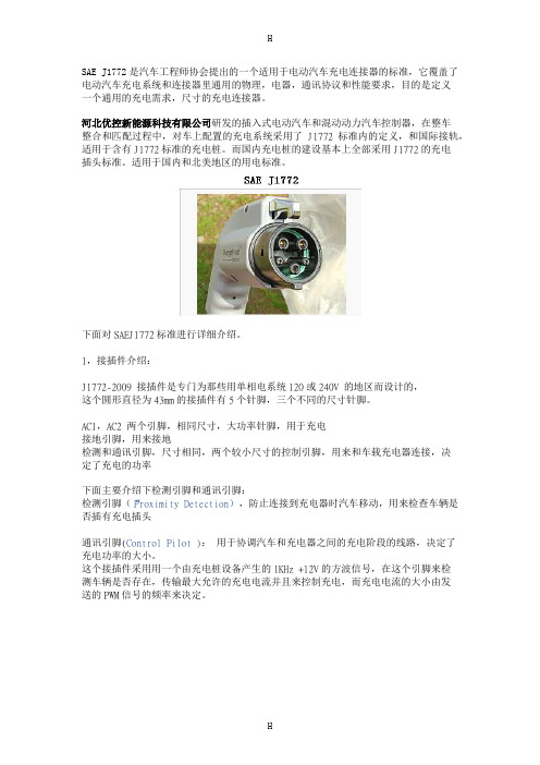
SAE J1772是汽车工程师协会提出的一个适用于电动汽车充电连接器的标准,它覆盖了电动汽车充电系统和连接器里通用的物理,电器,通讯协议和性能要求,目的是定义一个通用的充电需求,尺寸的充电连接器。
河北优控新能源科技有限公司研发的插入式电动汽车和混动动力汽车控制器,在整车整合和匹配过程中,对车上配置的充电系统采用了J1772标准内的定义,和国际接轨,适用于含有J1772标准的充电桩。
而国内充电桩的建设基本上全部采用J1772的充电插头标准。
适用于国内和北美地区的用电标准。
下面对SAEJ1772标准进行详细介绍。
1,接插件介绍:J1772-2009 接插件是专门为那些用单相电系统120或240V 的地区而设计的,这个圆形直径为43mm的接插件有5个针脚,三个不同的尺寸针脚。
AC1,AC2 两个引脚,相同尺寸,大功率针脚,用于充电接地引脚,用来接地检测和通讯引脚,尺寸相同,两个较小尺寸的控制引脚,用来和车载充电器连接,决定了充电的功率下面主要介绍下检测引脚和通讯引脚:检测引脚(“Proximity Detection),防止连接到充电器时汽车移动,用来检查车辆是否插有充电插头通讯引脚(Control Pilot ):用于协调汽车和充电器之间的充电阶段的线路,决定了充电功率的大小。
这个接插件采用用一个由充电桩设备产生的1KHz +12V的方波信号,在这个引脚来检测车辆是否存在,传输最大允许的充电电流并且来控制充电,而充电电流的大小由发送的PWM信号的频率来决定。
这个接插件设计可以承受10000此的连接/断开循环,这样的一个设计可以使接插件有27年的使用寿命,所以质量比较可靠。
注:在插入式充电电动汽车和混动动力汽车中,检测引脚会给控制器(VCU)和电池管理系统(BMS)信号,用来检车充电插头是否连接,如果连接后BMS控制器会根据电池组状态进行充电,而VCU(HCU)会防止在充电插头连接时车辆移动,用来提醒驾驶者。
美国SAE电动车标准

內容概述
定義之共通性電動車/插電式混合動力車(EV/PHEV)及充電電源車之傳導充 電方法 說明北美電動車(EV)感應式充電連接器最低介面相容性要求 電動車充電電壓及電流品質指引及標準
定址自動充電器除持續功率中斷外,且透過斷短暫中斷驅動後之重新啟動
複合電動及電池電動車用電動推進馬達評價性能之試驗法及條件
通訊要求及網路結構j22932以方程式結果說明行駛于電池電能消耗模式及電池電能維持模式下之效能因子ufutilityfactordefinitionsforpluginhybridelectricvehiclesusingtravelsurveydata充電式複合電動車使用旅途調查數據之效能因子定義j2841說明插電式電動車與公共電網間能量傳輸及其他應用之通訊要求與規格communicationbetweenpluginvehiclesandtheutilitygrid插電式電動車與公共電網間通訊j28471改版中無線充電通訊使用案例usecasesforwirelesschargingcommunicationbetweenpluginelectricvehiclesandtheutilitygrid插電式電動車與公共電網間無線充電通訊使用案例j23866工作展開中說明插電式電動車pev與其顧客間使用案例usecasesforcommunicationbetweenpluginvehiclesandtheircustomers插電式電動車與其顧客間通訊使用案例j23865工作展開中說明插電式電動車與電動車供電驗裝置間診斷使用案例usecasesfordiagnosticcommunicationforpluginvehicles插電式電動車診斷通訊使用案例j23864工作展開中說明插電式電動車與公共電網間于逆送電之通訊使用案例usecasesforcommunicationbetweenpluginvehiclesandtheutilitygridforreversepowerflow插電式電動車與公共電網間于逆送電之通訊使用案例j23863工作展開中說明插電式電動車與電動車充電設備evse間于能量傳輸及其他應用之通訊使用案例usecasesforcommunicationbetweenpluginvehiclesandthesupplyequipmentevse插電式電動車與電動車充電設備evse之通訊使用案例j23862工作展開中說明插電式電動車與公共電網間于能量傳輸及其他應用之通訊使用案例usecasesforcommunicationbetweenpluginvehiclesandtheutilitygrid插電式電動車與公共電網間之通訊使用案例j23861說明道路非道路onoffroadlandbas
电动汽车传导式充电接口全球标准介绍
电动汽车传导式充电接口全球标准介绍电动汽车的发展正在推动汽车,电力及能源产业的变革。
在这一新兴产业中,标准化的进程至关重要,比如关于电动汽车和充电基础设施之间的充电接口标准,就影响了不同车型在不同国家和地区的电网之间如何快速,简便的进行电能的补充。
?目前全球主要采用的传导式充电接口系统有:?IEC?62196-1,2:2012年1月发布,主要被欧洲国家所采用的交流充电标准。
?IEC?62196-3:目前还在制定过程中,预计2014年制定完成。
主要内容是对直流充电接口的定义。
?SAE?J1772:2010年1月发布,是最早实施的充电接口标准,被美国及日本广泛使用。
其5芯的交流充电接口,在IEC?62196-2中被定义为type?1接口。
?CHAdeMO:该协会于2010年3月15日成立,成员单位大多数来自日本,主旨为推进快速充电规格在日本的统一,因此主要被日本车厂所采用。
?GB/T?20234.1,2,3-2011:2011年12月颁布,2012年3月实施,共三部分组成,形式接近于IEC?62196-1,2,3。
虽然目前是国标推荐标准,但解决了中国国内不同地区,不同电网公司,充电接口不统一的问题。
?为了更好的对标准进行介绍,下面先列举标准中常用的充电接口术语定义(图1)。
图1 标准中对充电接口各部分的术语定义供电插座?socket-outlet:供电接口中和电源供电线缆或供电设备连接在一起且固定安装的部分。
?供电插头?plug:供电接口中和充电线缆连接且可以移动的部分。
?车辆插座?vehicle?inlet:车辆接口中固定安装在电动汽车上,并通过电缆和车载充电机或车载动力蓄电池相互连接的部分。
?车辆插头?vehicle?connector:车辆接口中和充电线缆连接且可以移动的部分。
?不同标准的车辆插座界面比较(图2)图2?各国主要充电接口标准的比较传导式充电采用的方式?在目前的电动汽车传导式电能补给过程中主要采用两种方式:直流充电(DC)和交流充电(AC)。
- 1、下载文档前请自行甄别文档内容的完整性,平台不提供额外的编辑、内容补充、找答案等附加服务。
- 2、"仅部分预览"的文档,不可在线预览部分如存在完整性等问题,可反馈申请退款(可完整预览的文档不适用该条件!)。
- 3、如文档侵犯您的权益,请联系客服反馈,我们会尽快为您处理(人工客服工作时间:9:00-18:30)。
SAE Charging Configurations andel 1 (SAE J1772™) PEV includes on-board charger 120V, 1.4 kW @ 12 amp 120V, 1.9 kW @ 16 amp Est. charge time: PHEV: 7hrs (SOC* - 0% to full) BEV: 17hrs (SOC – 20% to full) DC Level 1 (SAE J1772™) EVSE includes an off-board charger 200-500 V DC, up to 40 kW (80 A) Est. charge time (20 kW off-board charger): PHEV: 22 min. (SOC* 0% to 80%) BEV: 1.2 hrs. (SOC – 20% to 100%) DC Level 2 (SAE J1772™) EVSE includes an off-board charger 200-500 V DC, up to 100 kW (200 A) Est. charge time (45 kW off-board charger): PHEV: 10 min. (SOC - 0% to 80%) BEV: 20 min. (SOC – 20% to 80%)
Notes: 1) BEV (25 kWh usable pack size) charging always starts at 20% SOC, faster than a 1C rate (total capacity charged in one hour) will also stop at 80% SOC instead of 100% 2) PHEV can start from 0% SOC since the hybrid mode is available. ver. 100312
AC level 2 (SAE J1772™) PEV includes on-board charger (see below for different types) 240 V, up to 19.2 kW (80 A) Est. charge time for 3.3 kW on-board charger PEV: 3 hrs (SOC* - 0% to full) BEV: 7 hrs (SOC – 20% to full) Est. charge time for 7 kW on-board charger PEV: 1.5 hrs (SOC* - 0% to full) BEV: 3.5 hrs (SOC – 20% to full) Est. charge time for 20 kW on-board charger PEV: 22 min. (SOC* - 0% to full) BEV: 1.2 hrs (SOC – 20% to full) Voltages are nominal configuration voltages, not coupler ratings Rated Power is at nominal configuration operating voltage and coupler rated current Ideal charge times assume 90% efficient chargers, 150W to 12V loads and no balancing of Traction Battery Pack