Continuous-curvature path planning for car-like vehicles
基于Matlab的多约束自动平行泊车轨迹规划
Trajectory planning of automatic parallel parking with multi-constraints based on Matlab
LI Hong1, GUO Konghui1, 2, SONG Xiaolin1, LI Feilong1
(1. State Key Laboratory of Advanced Design and Manufacturing for Vehicle Body, Hunan University, Changsha 410082, China; 2. State Key Laboratory of Automobile Dynamic Simulation, Jilin University, Changchun 130022, China) Abstract: Parking trajectory characteristics were analyzed, and a new trajectory function was proposed based on the known trajectory functions. It was proved that the new function was feasible for trajectory planning by parking trajectory fitting comparison. Potential collision points were analyzed and constraint equations were established accordingly. The orientation constraints at the start point, the location constraint at the parking point and the restriction of vehicle were considered, and the constraint equations were established respectively. Parking trajectory optimization function was presented to minimize the vehicle orientation angle at the parking point with restrictions mentioned above. The approach was used by trajectory planning for general parking space and tight parking space, and the trajectory function was solved using Matlab software. The simulation results show that the car can reverse into parking set safely in general parking space, with the continuously trajectory curvature and the car paralleled with the parking set at the parking point. This approach fails to make the car paralleled with the parking set in tight parking space, but the car can move into parking set safely with the continuous trajectory curvature. It is proved that the approach proposed can find a collision-free path in different parking spaces and meet the demand of continuous trajectory curvature, so the problem of shutting down to steer the wheel in parking process is solved. Key words: trajectory planning; automatic parking; collision-free; multi-constraints; optimization
Continuous-curvature path planning for car-like vehicles
Keywords | mobile-robot, path-planning, non-holonomic-system. Acknowledgements | this work was partially supported by the InriaInst. Nat. de Recherche en Informatique et en Automatique. Lab. d'Informatique GRAphique, VIsion et Robotique de Grenoble. Inst. Nat. de Recherche sur les Transports et leur Securite.
Continuous-Curvature Path Planning for Car-Like Vehicles
Inria Rh^ne-Alpes & Graviry o Zirst. 655 avenue de l'Europe. 38330 Montbonnot Saint Martin. France Alexis.Scheuer, Thierry.Fraichard]@inria.fr
A. Scheuer and Th. Fraichard
June 30, 1997
In this paper, we consider path planning for a car-like vehicle. Previous solutions to this problem computed paths made up of circular arcs connected by tangential line segments. Such paths have a non continuous curvature pro le. Accordingly a vehicle following such a path has to stop at each curvature discontinuity in order to reorient its front wheels. To remove this limitation, we add a continuous-curvature constraint to the problem at hand. In addition, we introduce a constraint on the curvature derivative, so as to re ect the fact that a car-like vehicle can only reorient its front wheels with a nite velocity. We propose an e cient solution to the problem at hand that relies upon the de nition of a set of paths with continuous curvature and maximum curvature derivative. These paths contain at most eight pieces, each piece being either a line segment, a circular arc of maximum curvature, or a clothoid arc. They are called SCC-paths (for Simple Continuous Curvature paths). They are used to design a local path planner, i.e. a non-complete collision-free path planner, which in turn is embedded in a global path planning scheme. The result is the rst path planner for a car-like vehicle that generates collision-free paths with continuous curvature and maximum curvature derivative. Experimental results are presented.
安全工作计划循环简称英文
Introduction:The Safety Work Plan Cycle (SWPC) is a structured and systematic approach to managing safety in the workplace. It ensures that allsafety-related activities are planned, executed, monitored, and reviewed on a continuous basis. This cycle is designed to minimize risks, prevent accidents, and create a safe working environment. The following document outlines the key components of the SWPC, aiming to provide a comprehensive guide for organizations to implement and maintain an effective safety management system.1. Identification of Hazards:The first step in the SWPC is to identify potential hazards in the workplace. This involves conducting thorough risk assessments, analyzing past incidents, and considering the nature of the work being performed. It is crucial to involve all stakeholders, including employees, management, and safety professionals, in this process to ensure a comprehensive understanding of the hazards.2. Risk Assessment:Once hazards are identified, the next step is to assess the associated risks. This involves evaluating the likelihood and severity of potential harm. A risk assessment matrix or similar tool can be used to prioritize risks based on their level of severity and likelihood. The goal is to determine which risks require immediate attention and which can be managed through ongoing controls.3. Control Measures:After identifying and assessing risks, appropriate control measures must be implemented to mitigate or eliminate them. These measures can include engineering controls, administrative controls, and personal protective equipment (PPE). It is essential to consider the most effective and practical controls for each risk, taking into account the organization's resources and the specific working conditions.4. Implementation:The implementation phase involves putting the control measures into action. This includes providing training to employees on the safe use of equipment, proper handling of hazardous materials, and adherence to safety procedures. Regular safety meetings and toolbox talks can also be conducted to reinforce safety awareness and ensure that employees are aware of any changes in the SWPC.5. Monitoring and Auditing:Continuous monitoring and auditing are critical to ensure that the SWPC is effective. Regular inspections, safety observations, and incident investigations should be conducted to identify any deviations from the planned safety measures. This phase also involves reviewing safety data, analyzing trends, and identifying areas for improvement.6. Review and Improvement:The SWPC is a dynamic process that requires regular review and improvement. A review committee or safety committee should meet periodically to discuss the effectiveness of the safety measures, identify any gaps, and propose enhancements. This review process should be documented and used to update the safety work plan accordingly.7. Communication and Training:Effective communication is vital throughout the SWPC. All employees should be informed about the safety policies, procedures, and any changes that occur. Regular training sessions should be conducted to ensure that employees are equipped with the necessary knowledge and skills to perform their tasks safely. Additionally, a clear reporting system should be established for employees to report near-misses, incidents, and suggestions for improvement.8. Documentation and Record Keeping:Proper documentation is essential for the SWPC. All safety-related activities, including risk assessments, control measures, training records, and incident reports, should be thoroughly documented. Thisdocumentation serves as a reference for future reviews and audits and helps in demonstrating compliance with safety regulations.Conclusion:The Safety Work Plan Cycle (SWPC) is a comprehensive framework for managing safety in the workplace. By following this cycle, organizations can ensure that safety is given due importance, and risks areeffectively managed. Continuous improvement, communication, and training are key elements of the SWPC, which ultimately contribute to a safer and healthier work environment for all employees.。
车辆自动驾驶的路径规划-开题报告

查阅范围:车辆智能驾驶,路径规划、跟踪,机器人智能控制,Matlab仿真
网络资源
东北大学图书馆-超星数字图书数据库;东北大学图书馆-万方学位论文数据库
东北大学图书馆-中国优秀博硕士学位论文全文数据库
东北大学图书馆-中国期刊全文数据库;东北大学图书馆-Elsevier Science数据库
2.主要设计内容
a)对智能车辆进行功能分析。
b)绘出控制部分的框图以及关键部分或部件的原理图结构图等。
c)对遥控车进行结构改装。
d)确定车辆的精确定位方法。
e)确定车辆的路径跟踪策略。
f)建立车辆的运动控制模型。
g)进行指定8字形路径的自动驾驶实验,获取实验数据,得出控制规律。
h)用MATLAB的SIMULINK模块进行控制系统的计算机仿真。
随着计算机技术、电子技术、图像处理等信息处理技术研究的发展,研究人员开始将各种先进的技术应用于汽车控制上,从而辅助驾驶员进行汽车的操纵控制,如目前已经实用化的制动防抱控制系统、驱动力控制系统、四轮转向系统以及汽车稳定性控制系统等。在这些汽车电子控制系统研究的基础上,结合蓬勃发展的智能化信息处理技术,逐步产生了一个新兴的交叉学科-车辆的自动驾驶(又称为智能汽车)。未来实用化的智能汽车将最大限度地减少交通事故、提高运输效率、减轻驾驶员操纵负担,从而提高整个道路交通的安全性、机动性与汽车行驶的主动安全性。科技部于2001年已正式启动实施了十五计划中的国家科技攻关计划重大项目“智能交通系统关键技术开发和示范工程”来提高我国整个运输系统的管理水平和服务水平,提高效率和安全性,车辆的自主驾驶是实现ITS的关键。
d)建立车辆的运动控制模型。
e)实验数据测定分析(遥控车速度,转向角,曲率,转向电机转速等)+实验数据准确性验证。
智能车辆自由换道模型研究_李玮
第27卷 第2期2010年2月 公 路 交 通 科 技Journal of Highway and Transportation Research and DevelopmentVol .27 No .2 Feb .2010文章编号:1002-0268(2010)02-0119-05收稿日期:2008-12-22基金项目:北京市教委重点项目;北京市自然科学基金资助项目(JJ002790200802)作者简介:李玮:(1982-),男,河北廊坊人,博士研究生,从事机器视觉、网络智能控制与嵌入式系统研究.(l iwei727@126.c om )智能车辆自由换道模型研究李 玮,高德芝,段建民(北京工业大学 电子信息与控制工程学院,北京 100124)摘要:针对传统的车辆换道模型在换道过程中存在着侧向加速度过大或产生跃变、轨迹曲率不连续以及换道过程起始时刻侧向加速度不为零的问题,以四段式车道变换理论为基础,提出一种新的车辆自由换道轨迹函数,并引入B 样条理论对换道轨迹进行再规划,进而建立一种新的高速公路车辆自由换道模型。
该模型能够较好的解决传统车道变换模型存在的上述缺陷。
给定车辆换道轨迹性能评价参数,利用M atlab 仿真计算得到新模型产生的换道轨迹,并与另外两种换道模型产生的轨迹进行对比分析。
分析结果验证了该模型的正确性及有效性。
关键词:交通工程;换道模型;B 样条曲线;再规划;侧向加速度中图分类号:U491 文献标识码:AResearch on Lane Change Model for Intelligent VehiclesLI Wei ,GAO Dezhi ,DUAN Jianmin(School of Electronic Information and Control Engineering ,Beijing Universit y of Technology ,Beijing 100124,China )Abstract :Traditional lane change models in the process of lane changing have defects such as the lateral acceleration is too high or have jumps ,the path has a noncontinuous curvature profile ,and the lateral acceleration at initial moment in the process of lane changing is not zero .A new lane change function based on principle of four -phase lane changing model was put for ward and the lane change path was rebuilt by adopting B -spline theory ,at last a new lane change model for vehicles on highway was built .The ne w model could resolve the abovementioned existent defects in traditional models .With the given evaluation para meters of the lane changing path ,the lane change path from this new model was calculated by Matlab software ,and compared with the lane changing paths from two traditional models .The analysis result proved the corr ectness and feasibility of this ne w lane change model .Key words :traffic engineering ;lane change model ;B -spline curve ;r eplan ;lateral acceleration 0 引言智能车辆(Intelligent Vehicle ,简称IV ),是一个集环境感知、规划决策、多等级辅助驾驶等功能于一体的综合系统,是众多高新技术综合集成的载体。
计划实践总结再计划再实践再总结;英语缩写

计划实践总结再计划再实践再总结;英语缩写Plan, Practice, Summarize: A Continuous Cycle of ImprovementIn the realm of personal and professional development, the cycle of planning, practicing, and summarizing is a pivotal framework for continuous improvement. This iterative process, often abbreviated as PPS, encompasses the key stages of setting goals, implementing strategies, assessing results, and refining approaches. Planning: Laying the Foundation for SuccessThe initial phase of the PPS cycle involves meticulous planning, which sets the stage for all subsequent activities. Planning entails the identification of specific, measurable objectives that align with one's broader goals and aspirations. This phase requires a deep understanding of the current situation, including strengths, weaknesses, opportunities, and threats. By analyzing these factors, individuals can craft a roadmap that outlines the steps needed to achieve their desired outcomes. Effective planning also involves the allocation of resources, whether it be time, money, or other assets. This ensures that efforts are focused on the most impactful activities while minimizing wasted effort. Additionally, planning should incorporate contingency measures to mitigate potential risks and obstacles that may arise during the implementation phase.Practice: Translating Plans into ActionThe second phase of the PPS cycle is practice, where plans are translated into tangible actions. This phase requires discipline, focus, and adaptability. It involves executing the strategies outlined in the planning phase while remaining flexible enough to adjust course when faced with unexpected challenges.During the practice phase, it is essential to track progress and measure performance against the predefined objectives. This helps individuals stay on track and identifies areas where additional effort or modification may be necessary. Practice also involves seeking feedback from others, as external perspectives can provide valuable insights and suggestions for improvement.Summarize: Reflecting on Results and Refining StrategiesThe final phase of the PPS cycle is summarization, where individuals reflect on their results and refine their strategies accordingly. This phase involves a critical analysis of what worked well, what didn't, and why. It requires honest self-assessment and a willingness to acknowledge both successes and failures. Summarization is not just about identifying weaknesses but also recognizing strengths and opportunities for further growth. This phase provides valuable insights that inform future planning and help individuals avoid repeating past mistakes. By reflecting on their experiences, individuals can refine their approaches, set more realistic and achievable goals, and ultimately accelerate theirprogress.The Iterative Nature of PPSThe beauty of the PPS cycle lies in its iterative nature. Each phase feeds into the next, creating a continuous loop of improvement. As individuals progress through the cycle, they gain a deeper understanding of their capabilities, challenges, and opportunities. This enables them to set more informed goals, develop more effective strategies, and achieve better results.Moreover, the PPS cycle promotes a mindset of continuous learning and adaptation. It encourages individuals to view failures as opportunities for growth and to embrace change as a necessary component of success. By adopting this mindset, individuals can navigate the ever-changing landscapes of their personal and professional lives with confidence and resilience.ConclusionIn conclusion, the PPS cycle – Plan, Practice, Summarize – is a powerful tool for personal and professional development. It provides a structured framework for setting goals, implementing strategies, assessing results, and refining approaches. By embracing this iterative process, individuals can continuously improve themselves and achieve their desired outcomes. As they progress through the cycle, they gain valuable insights that inform future actions and accelerate their progress towards success.。
Solidworks术语中英文对照
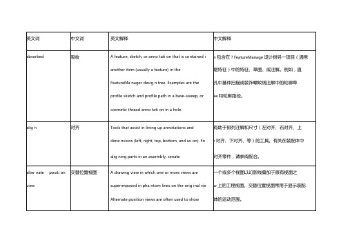
区域剖面线
A crosshatch pattern or fill applied to a selected fa
C应用到一所选的面或工程图中一关闭的草图
or to a closed sketch in a draw ing. Seeosshatch
上的剖面线样式或填充。另请参阅 剖面线。
(1)附加到注释、块、或其它注解的引线端点。
block, or other anno tati on. Seettachme nt point (2)
另请参阅附加点。(2)图纸格式包含材料明细
Sheet formats con tai n an chor poi nts for a bill of
表、孔表、修订表、以及焊件切割清单的定位
connecting rod or cyli nder. This new assembly ca
n装配体。SolidWorks装配体文件名称的扩展名
the n be used as a subassembly in an assembly o'
:an
engine. The extension for a SolidWorks assembly n ame is .SLDASM. Seeubassemblymate.
ra同的文件内。例如,活塞是一个可在装配体内
from the assembly. For example, in an assembly,
a与其它零件,如连杆或室,相配合的零件。此
piston can be mated to other parts, such as a
活塞装配体然后可在发动机装配体中用作子
,准目标、形位公差符号、焊接符号、零件序号
铁路桥梁名词术语
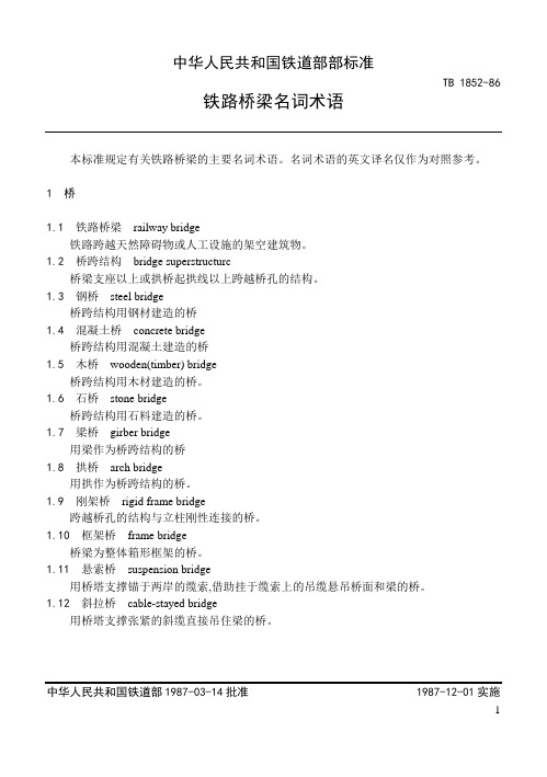
中华人民共和国铁道部部标准TB 1852-86铁路桥梁名词术语本标准规定有关铁路桥梁的主要名词术语。
名词术语的英文译名仅作为对照参考。
1 桥1.1铁路桥梁railway bridge铁路跨越天然障碍物或人工设施的架空建筑物。
1.2桥跨结构bridge superstructurc桥梁支座以上或拱桥起拱线以上跨越桥孔的结构。
1.3钢桥steel bridge桥跨结构用钢材建造的桥1.4混凝土桥concrete bridge桥跨结构用混凝土建造的桥1.5木桥wooden(timber) bridge桥跨结构用木材建造的桥。
1.6石桥stone bridge桥跨结构用石料建造的桥。
1.7梁桥girber bridge用梁作为桥跨结构的桥1.8拱桥arch bridge用拱作为桥跨结构的桥。
1.9刚架桥rigid frame bridge跨越桥孔的结构与立柱刚性连接的桥。
1.10框架桥frame bridge桥梁为整体箱形框架的桥。
1.11悬索桥suspension bridge用桥塔支撑锚于两岸的缆索,借助挂于缆索上的吊缆悬吊桥面和梁的桥。
1.12斜拉桥cable-stayed bridge用桥塔支撑张紧的斜缆直接吊住梁的桥。
中华人民共和国铁道部1987-03-14批准 1987-12-01实施1TB 1852-861.13开合桥movable bridge桥跨结构中一跨或两跨可以提升、平转或立转开合的桥。
1.14浮桥pontoon(floating)bridge用筏、浮箱或平底船代替桥墩或桥跨结构的桥。
1.15上承桥deck bridge桥面位于桥跨结构上部的桥。
1.16中承桥bridge with floor at its middepth桥面位于桥跨结构中部的桥。
1.17 下承桥through bridge桥面位于桥跨结构下部的桥。
1.18单线桥single-track bridge仅能铺设一条铁路线路的桥。
智能车大角度弯道转向曲率连续的轨迹规划方法

术 。 [3] 目前有不少关于智能车辆轨迹规划技术方面
的研究文献,其中 大 多 数 方 法 是 在 离 散 状 态 空 间 中提供有效的计 算 方 法,然 而 用 此 方 法 生 成 的 轨 迹不光 滑,不 满 足 车 辆 运 动 学 的 可 行 性[4]。Du灢 bins算法是生成平 滑 轨 迹 最 有 名 的 算 法 之 一,在 Dubins算法 中,最 短 轨 迹 由 圆 弧 和 直 线 组 成 。 [5] 但是该轨迹有一 个 缺 点,即 在 圆 弧 和 直 线 的 节 点 处 轨 迹 的 曲 率 不 连 续 ,对 该 轨 迹 进 行 循 迹 行 驶 ,车 辆必须在轨迹不 连 续 的 地 方 停 下 来,重 新 调 整 车 辆的前轮转向,这 对 于 连 续 行 驶 的 车 辆 来 说 是 不 可 取 的 ,所 以 在 实 际 应 用 中 ,轨 迹 曲 率 连 续 是 保 证 车辆顺畅行驶的前提条件[6]。B 样 条 曲 线 具 有 曲 率连续的优点,所以有很多文献对其进行研 究 。 [7] 毬样条曲线在 B样条曲线的基础上增加了一些新 的参量,可以不用 改 变 控 制 顶 点 而 通 过 调 整 新 引 入的参量来改变曲线的形状,这样,基于毬 样条曲 线进行轨迹规划的方法的推广性和灵活性更
1暋 车 辆 模 型
智 能 车 简 化 的 车 辆 模 型 示 意 图 见 图 1,其 中 , 车辆前轮用作 转 向 轮,后 轮 用 作 驱 动 轮。i(x,y) 为车辆后轴中心的位置;毴为车辆相对于x 轴的方 向角;氄 为前轮转角;l为前后轴之间的轴距;R 为 车辆的转弯半径;v和氊 分别为车辆在点(x,y)处
Smooth path planning平滑路径规划
Example
Path define by (p1,p2,p3,p4,p5,p6)
~ sym(p 4 , p5 ) ~ sym(p5 , p 6 )
Robótica Móvel
2002 - © Pedro Lima, M. Isabel Ribeiro
Motion Planning
Overview of the Method
•
A size d of a deflection α of a pair (p1,p2) of a symmetric posture pair, sym (p1,p2) p2
April.2002
All the rights reserved
Robótica Móvel
2002 - © Pedro Lima, M. Isabel Ribeiro
Motion Planning
References
–
Smooth Path Planning
• Y.Kanayama, B. Hartman, “Smooth Local Path Planning for Autonomous Vehicles”, in Autonomous Robot Vehicles, edited by Cox, Wilfong, Springer, 1990, pp.62-67.
Motion Planning
Problem Solution
拖拉机自动驾驶系统上线轨迹规划方法
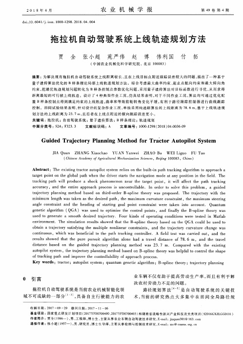
农 业 机 械 学 报
doi:10.6041/j.issn.1000—1298.2018.04.004
第49卷第4期
拖 拉 机 自动 驾驶 系统 上 线 轨 迹规 划方 法
贾 全 张小 超 苑 严 伟 赵 博 伟 利 国 付 拓
(中 国农 业 机 械 化 科 学 研 究 院 ,北 京 100083)
used to generate a smooth desired trajectory.Four kinds of operating conditions were tested in Matlab
environment.The simulation results showed that the B—spline theory based on the QGA could be used to obtain a trajectory satisfying the multiple nonlinear constraints,and the trajectory curvature change was
tracking path will produce a shock phenomenon near the target point, it will affect the path tracking
accuracy, and the entire approach process is uncontrollable. In order to solve this problem , a guided
Guided Trajectory Planning M ethod for Tractor Autopilot System
关键路径图英语作文
关键路径图英语作文Title: Understanding Critical Path Method in Project Management。
In project management, the critical path method (CPM) is a crucial tool used to schedule and manage complex projects effectively. It involves creating a visual representation known as a critical path diagram, which helps project managers identify the sequence of tasks and determine the longest path to project completion. In this essay, we will delve into the concept of critical path method and explore its significance in project planning and execution.To begin with, let's define what the critical path is. The critical path is the longest sequence of dependent tasks and activities that must be completed on time for the project to finish within its allotted schedule. Any delay in the critical path activities will directly impact the project's overall timeline. Therefore, identifying andmanaging the critical path is paramount to ensure timely project delivery.Creating a critical path diagram involves several steps. First, all the tasks required to complete the project are listed along with their durations and dependencies. Dependencies denote the relationship between tasks, indicating which tasks must be completed before others can begin. Once the task list is compiled, a network diagram is constructed, illustrating the sequence of tasks and their dependencies. This diagram forms the basis for identifying the critical path.The critical path is determined by calculating the earliest start and finish times for each task, as well as the latest start and finish times without delaying the project. Tasks that have no flexibility in their start or finish times are considered critical and lie on thecritical path. Conversely, tasks that have some flexibility in their scheduling are known as non-critical tasks.Understanding the critical path provides severalbenefits in project management. Firstly, it allows project managers to focus their attention and resources on the most crucial tasks that directly impact project duration. By identifying the critical path, managers can allocate resources efficiently, prioritize activities, and mitigate risks that could potentially cause delays. Additionally, it facilitates effective communication among project team members, as everyone understands which tasks are critical and must be completed on time.Moreover, the critical path method enables project managers to perform schedule compression techniques if necessary. Schedule compression involves shortening the project duration without sacrificing project quality. By identifying non-critical tasks that have some flexibility, managers can explore options such as crashing or fast-tracking to accelerate project completion while keeping the critical path intact.Furthermore, the critical path method assists in monitoring project progress and identifying deviations from the planned schedule. Regularly updating the critical pathdiagram allows project managers to track the completion status of critical tasks and take corrective actions if any delays occur. This proactive approach helps minimize the impact of unforeseen events or changes in project scope.In conclusion, the critical path method is a valuable tool in project management for planning, scheduling, and controlling project activities. By creating a critical path diagram, project managers can identify the longest sequence of tasks and prioritize their efforts accordingly. Understanding the critical path enables effective resource allocation, risk management, and schedule compression techniques to ensure successful project delivery. Intoday's dynamic business environment, mastering thecritical path method is essential for managing projects efficiently and achieving desired outcomes.。
再培训计划英语
再培训计划英语IntroductionAs the world rapidly evolves and industries constantly change, it is crucial for employees to stay current with the latest skills and knowledge in their field. Re-training programs can significantly contribute to the professional development of employees and allow them to adapt to new technologies and methods. This re-training plan will outline the objective, scope, and methods of implementation for re-training employees in a specific industry.ObjectiveThe main objective of the re-training program is to update the employees' skills and knowledge to ensure their continued relevance in a rapidly changing industry. The program aims to improve their proficiency in the use of new technologies, enhance their problem-solving abilities, and increase their productivity and performance.ScopeThe re-training program will target employees in the technology sector who need to develop new skills to adapt to the ever-changing demands of the industry. The program will encompass various areas such as data analysis, programming languages, cybersecurity, and project management. The scope of the re-training program will also include soft skills training, such as communication, teamwork, and leadership, to ensure employees are well-rounded and capable of handling the challenges of their roles.Implementation PlanThe implementation of the re-training program will involve several key steps and strategies:1. Training Needs Assessment: The first step will be to conduct a thorough assessment of the training needs of the employees. This will involve identifying the specific skills and knowledge gaps that need to be addressed.2. Curriculum Development: Based on the training needs assessment, a curriculum will be developed that encompasses the necessary training modules and materials. The curriculum will cover technical skills, soft skills, and industry-specific knowledge.3. Training Delivery: The next step will be to deliver the training through a combination ofin-person workshops, online courses, and on-the-job training. The training will be conducted by experienced industry professionals and trainers who are experts in their respective fields.4. Monitoring and Evaluation: Throughout the re-training program, the progress of the employees will be closely monitored and evaluated. This will involve regular assessments, feedback sessions, and performance reviews to track the effectiveness of the program.5. Support and Follow-Up: After completion of the re-training program, ongoing support and follow-up will be provided to the employees to ensure they continue to apply their new skills and knowledge in their roles.Training ModulesThe re-training program will consist of the following modules:1. Data Analysis: This module will cover the latest data analysis tools and techniques, including data mining, data visualization, and statistical analysis.2. Programming Languages: Employees will be trained in popular programming languages such as Python, Java, and C++, as well as web development languages like HTML, CSS, and JavaScript.3. Cybersecurity: This module will focus on the fundamentals of cybersecurity, including threat detection, incident response, and risk management.4. Project Management: Employees will learn about project planning, scheduling, budgeting, and resource management to improve their ability to manage complex projects.5. Soft Skills: Training in soft skills such as effective communication, teamwork, leadership, and problem-solving will be integrated throughout the program.ConclusionRe-training programs are essential for employees to stay competitive and relevant in today's rapidly evolving industries. This re-training plan outlines the objective, scope, and methods of implementation for a comprehensive re-training program in the technology sector. By updating employees' skills and knowledge, the program will ensure that they are well-equipped to tackle the challenges of their industry and contribute to the success of their organizations.。
研究内容与技术路线英语
研究内容与技术路线英语Diving into the heart of innovation, our research content and technological approach are meticulously crafted tonavigate the uncharted waters of discovery. At the forefrontof our exploration lies a commitment to harnessing cutting-edge methodologies that push the boundaries of what is known. We are not just researchers, but pioneers, forging a path through the dense forest of data with the sharp tools of technology.Our journey begins with a clear vision, a roadmap that outlines the milestones of our quest. Each step ismeticulously planned, from the initial hypothesis formulation to the final analysis and dissemination of findings. Our research content is a tapestry woven from threads ofcuriosity, creativity, and critical thinking, reflecting the diverse spectrum of knowledge we aim to contribute to.As we venture into the realm of technology, we embracethe power of advanced analytics, artificial intelligence, and machine learning, which serve as our compass, guiding us through the complexities of data interpretation. We are not merely consumers of technology but active participants in its evolution, constantly refining and adapting our tools tobetter serve our research goals.Our technological route is a dynamic one, evolving in response to the ever-changing landscape of scientific inquiry.We remain agile, ready to pivot and adapt as new challenges and opportunities arise. Collaboration is at the core of our ethos, as we recognize that the collective wisdom of our interdisciplinary team is the key to unlocking the mysteries we seek to understand.In essence, our research content and technological path are a testament to our dedication to excellence, a pursuit of knowledge that is both relentless and reverent. We stand at the intersection of science and technology, ready to illuminate the path forward for generations to come.。
河流因为弯曲,所以通过了阻碍,作文立意

河流因为弯曲,所以通过了阻碍,作文立意英文版The Flow of Life: How Rivers Overcome Obstacles Through Their CurvesIn the natural world, rivers are not straight lines but rather dynamic paths of continuous curvature. This curvature, often unnoticed, plays a pivotal role in the river's journey, allowing it to traverse obstacles and continue its onward flow. This principle, when applied metaphorically, can offer profound insights into the challenges and triumphs of life.Just as rivers encounter boulders, fallen trees, and other obstacles, our lives are filled with roadblocks and difficulties. The river, instead of crashing into these obstacles head-on, gracefully curves around them, finds a new path, and continues its journey. Similarly, when faced with challenges, we can choose to either stubbornly persevere in a straight path thatleads to nowhere or embrace the curve, learn from it, and find a new way forward.The curvature of a river is not a weakness but a strength. It allows the river to flow freely, adapting to the changing terrain and overcoming obstacles that would hinder its progress. In the same way, the curves of life teach us resilience, adaptability, and wisdom. They shape us, make us stronger, and prepare us for the next obstacle.The river's journey is not just about reaching a destination; it's about the process of growth and transformation. Each curve represents a lesson learned, a challenge overcome, and a step closer to the ocean. Similarly, in life, the curves are what make the journey worth taking. They are the moments of growth, the lessons learned, and the obstacles overcome that make us stronger and wiser.As rivers flow through life, so do we. We encounter obstacles, we curve around them, and we continue on our journey. It is not the destination that matters most; it is thejourney itself, the curves, the lessons, and the growth that define our existence. Let us embrace the curves of life, learn from them, and flow freely towards our destined oceans.中文版生命的流动:河流如何通过弯曲克服障碍在自然界中,河流并非直线,而是充满动态曲线的路径。
基于多项式优化的车辆自主换道轨迹规划

10.16638/ki.1671-7988.2021.011.004基于多项式优化的车辆自主换道轨迹规划*施卫,夏涛(江苏理工学院汽车与交通工程学院,江苏常州213001)摘要:换道轨迹的规划是车辆能否自主换道的基础和关键,文章基于五次多项式的轨迹规划方法来拟合换道轨迹,依据换道初始时刻和结束时刻车辆的状态量进行轨迹求解运算,规划出一条光滑连续且符合实际的轨迹曲线。
同时考虑到换道的舒适性和效率性,建立了轨迹优化函数J,通过引入k1和k2两个权重系数进行分析,得出了不同权重比下的换道最优时间,使得车辆的换道轨迹更加优化。
在Carsim/Simulink中进行仿真实验,结果表明提出的换道轨迹优化的方法是可行的。
关键词:自主换道;五次多项式;轨迹规划;轨迹优化中图分类号:U461.91 文献标识码:B 文章编号:1671-7988(2021)11-10-04Trajectory Planning of Vehicle Autonomous Lane Change basedon Polynomial Optimization*Shi Wei, Xia Tao(Jiangsu University of Technology, School of Automobile and Traffic Engineering, Jiangsu Changzhou 213001)Abstract: Lane change trajectory planning is the basis and key to whether a vehicle can change lanes autonomously. In this paper, lane change trajectories are fitted based on the path planning method of the quintic polynomial. A smooth, continuous and practical trajectory curve is planned according to the state quantity of the vehicle at the initial and final time of lane change. At the same time, considering the comfort and efficiency of lane change, the trajectory optimization function J was established. By introducing two weight coefficients k1 and K2 for analysis, the optimal lane change time under different weight ratios was obtained, making the lane change trajectory of vehicles more optimized. Simulation experiments in Carsim/Simulink show that the proposed method is feasible.Keywords: Independent lane change; Quintic polynomials; Trajectory planning; Trajectory optimizationCLC NO.: U461.91 Document Code: B Article ID: 1671-7988(2021)11-10-04前言车辆换道在驾驶过程中是非常普遍的,数据表明交通事故中有一部分的原因就是车辆进行车道更换引起的。
探索适宜的工作方案英文
探索适宜的工作方案英文IntroductionIn today's fast-paced and demanding work environment, finding a suitable work schedule that balances productivity, employee satisfaction, and work-life balance has become a critical issue for organizations and individuals alike. This article aims to explore various work schedule options and their advantages and disadvantages, ultimately equipping employees and employers with the knowledge to create an optimal work environment. Traditional 9-to-5 ScheduleThe traditional 9-to-5 schedule, also known as the 40-hour workweek, has long been the standard in many industries. This schedule provides a consistent routine, allowing for better coordination and communication among team members. Additionally, it ensures that employees are available during regular business hours when most clients and stakeholders are active.However, the 9-to-5 schedule may not suit everyone. It can be restrictive for individuals with personal commitments or those whoprefer flexibility. Moreover, some employees may not be at their most productive during the traditional working hours. This has led to the exploration of alternative work schedules.FlextimeFlextime refers to a work schedule that allows employees to vary their starting and ending times within certain limits, while still fulfilling the required number of work hours. This approach provides employees with the freedom to choose when they work, enhancing work-life balance and employee satisfaction.Flextime empowers employees to align their work schedules with their personal preferences, allowing them to attend to personal commitments or utilize their peak productivity hours. This increased autonomy often leads to higher job satisfaction and improved employee morale. Additionally, employees who have flexible schedules report lower levels of stress and better work-life integration.However, implementing flextime can be a challenge for organizations. Coordinating team schedules and ensuringsufficient coverage during core business hours may become more complex. Communication and collaboration among team members may be affected when they have different working hours. Overcoming these challenges requires effective planning, communication, and leveraging technology to facilitate collaboration among team members.Compressed WorkweekAnother alternative work schedule gaining popularity is the compressed workweek. This schedule allows employees to work longer hours per day but fewer days per week. Common variations include the 4-day workweek, where employees work four 10-hour days, or the 9-day fortnight, where employees work eight 9-hour days over a two-week period.The compressed workweek offers benefits for both employees and organizations. Employees enjoy longer weekends, which can improve work-life balance, reduce commuting costs and improve job satisfaction. For organizations, it can lead to increased productivity, reduced absenteeism, and improved employeeretention rates.However, implementing a compressed workweek requires careful planning. Adjustments in shift scheduling, workload distribution, and ensuring adequate staffing during non-working days are essential to make this schedule work effectively. Communication and coordination among team members become more crucial to avoid disruption.Remote WorkRemote work, or telecommuting, has become increasingly popular due to technological advancements, especially during the COVID-19 pandemic. Remote work allows employees to work from locations other than the traditional office space, providing flexibility and eliminating commuting time. It offers advantages such as reduced office space needs, increased employee satisfaction, and access to a broader talent pool.For employees, remote work provides the freedom to work in their preferred environment, leading to increased productivity and work-life balance. Companies benefit from reduced overhead costsand the potential to attract and retain top talent from different geographic locations.However, remote work also poses challenges. It can lead to feelings of isolation, reduced team cohesion, and difficulties in achieving work-life separation. Effective communication and clearly defined expectations are crucial to overcome these challenges and ensure collaboration among remote team members. ConclusionIn the quest for suitable work schedules, exploring options beyond the traditional 9-to-5 model can enhance employee satisfaction, optimize productivity, and improve work-life balance. Flextime, compressed workweeks, and remote work present viable alternatives that offer unique advantages. However, each schedule requires careful consideration and planning to address potential challenges and ensure successful implementation. Organizations and individuals must evaluate their needs and priorities to determine the most suitable work schedule that maximizes productivity and employee well-being.。
matlab 连续曲率张力样条

在 MATLAB 中,如果想要拟合并绘制一条曲线,并且这条曲线需要保持一定程度的平滑性和连续性,可以使用连续曲率张力样条(Continuous Curvature Tension Spline,CCTS)。
MATLAB 中的cscvn函数可以用于创建一个 CCTS。
以下是一个简单的例子,演示如何使用cscvn函数:
在这个例子中:
•cscvn函数接受一个二维矩阵,其中包含 x 和 y 的坐标。
它返回一个spline结构,包含了样条的信息。
•fnval函数用于在给定参数值处计算样条上的点。
我们在这里使用linspace生成一些参数值。
•最后,通过plot函数绘制原始数据点和连续曲率张力样条。
请注意,CCTS 允许通过参数进行调整,以控制曲线的平滑性和张力。
可以在cscvn 的文档中找到更多关于这些参数的信息。
七轴机械手最小能量直线轨迹算法优化

七轴机械手最小能量直线轨迹算法优化梁赫西;黄晓东;周密【摘要】对比分析了伪逆法和最优能量算法的原理,给出了最优能量算法的优化方案.笛卡尔空间体系中采用齐次矩阵和四元数法获得位置和姿态的插值;利用优化后的最优能量算法求出逆解,得到与笛卡尔空间中对应的在关节空间中的关节值.文中给出了实际仿真实例,该实例表明本文给出的优化方案在满足正常作业情况下,相对于伪逆法,方案中四元数算法在姿态插值运算上更快并且能量优化效果更好,七轴机械手最小能量消耗节约10%~20%左右.【期刊名称】《微型机与应用》【年(卷),期】2015(034)015【总页数】4页(P1-4)【关键词】七轴机械手;能量;四元数【作者】梁赫西;黄晓东;周密【作者单位】湖北师范学院教育信息与技术学院,湖北黄石435002;湖北师范学院教育信息与技术学院,湖北黄石435002;武汉大学电子信息学院,湖北武汉430074【正文语种】中文【中图分类】TP241近年来,冗余度机械手末端执行器广泛应用于装配、喷涂、微操作等工业生产领域。
其主要沿直线轨迹进行作业,研究机械臂直线轨迹能量消耗对其实际应用至关重要。
目前在冗余机械手优化方面取得了许多有价值的研究成果,主要集中在逆运动学优化和直线轨迹规划两大方面。
参考文献[1]给出了一个雅可比矩阵的建立实例及其奇异性分析;参考文献[2]对逆运动学进行了实例分析;参考文献[3]和参考文献[4]提出了冗余机械手的逆运动优化的基于拓展的雅可比矩阵的算法;参考文献[5]中提出了一个求解等式最优化的不使用罚函数或滤子技术的信赖逐步二次规划方法及其全局收敛理论;参考文献[6]中Liu和Yuan等人优化了该理论,并提出了在线搜索逐步二次规划方法及其全局和局部收敛性理论。
在直线轨迹的规划方面,参考文献[7-9]提出了利用Hermite插值和条样、曲线插值等方法来进行直线轨迹规划;参考文献[10]和参考文献[11]则将四元数法引入到机械手轨迹规划的姿态规划中。
- 1、下载文档前请自行甄别文档内容的完整性,平台不提供额外的编辑、内容补充、找答案等附加服务。
- 2、"仅部分预览"的文档,不可在线预览部分如存在完整性等问题,可反馈申请退款(可完整预览的文档不适用该条件!)。
- 3、如文档侵犯您的权益,请联系客服反馈,我们会尽快为您处理(人工客服工作时间:9:00-18:30)。
Continuous-CurvatuVehicles
CONTINUOUS-CURVATURE PATH PLANNING FOR CAR-LIKE VEHICLES
A. Scheuer and Th. Fraichard
Inria Rh^ne-Alpes & Graviry o Inria. Zirst. 655 av. de l'Europe. 38330 Montbonnot Saint Martin, France
Abstract: In this paper, we consider path planning for a car-like vehicle. We de ne a new problem adding to the classical one a continuous-curvature constraint and a bound on the curvature derivative, so as to re ect the fact that a car-like vehicle can only reorient its front wheels with a nite velocity. As optimal solutions can contain an in nity of pieces, we propose a solution to compute Sub-optimal Continuous Curvature paths, called SCC-paths. These paths contain at most eight pieces, each piece being either a line segment, a circular arc of maximum curvature, or a clothoid arc. Keywords: mobile-robot, non-holonomic-system, path-planning, uncertainty.
Institut National de Recherche en Informatique et en Automatique. Lab. d'Informatique GRAphique, VIsion et Robotique. Institut National de REcherche sur les Transports et leur Securite.
In this paper, we focus on the path planning problem for a car-like vehicle that goes only forward. Such a vehicle is subject to two nonholonomic constraints: it can only move along a direction perpendicular to its rear wheels axle (continuous tangent direction), and its turning radius is lower bounded (maximum curvature) (Barraquand and Latombe, 1989). Numerous works, e.g. (Barraquand and Latombe, 1989; Mirtich, 1992; Laumond et al., 1994; Svestka and Overmars, 1995a), have been done to plan paths for such vehicles, but almost all of them generate sequence of Dubins' curves (Dubins, 1957), i.e. paths made of circular arcs connected by tangential line segments. The main reason for this is that these paths are the shortest ones for such a vehicle (Dubins, 1957). The main drawback of these paths is that their curvature is not continuous. Accordingly a vehicle following such a path has to stop at each curvature discontinuity in order to reorient its front wheels. Since we are interested in planning forward paths only, i.e. paths without manoeuvres, we do not want the vehicle to stop, except possibly at the initial and nal con gurations. For this reason, we add a continuous-curvature constraint to the classical non-holonomic path planning problem for car-like vehicles. In addition, we introduce a constraint on the curvature derivative; it is upper bounded so as to re ect the fact that the
a b c
Praxitele programme on individual urban public transports 1993-1997], and the Inco-Copernicus ERB-IC15-CT96-0702 project \Multi-agent robot systems for industrial applications in the transport domain" 1997-1999].
A. Scheuer and Th. Fraichard a b
Abstract | In this paper, we consider path planning for a car-like vehicle. We de ne a new problem adding to the classical one a continuous-curvature constraint and a bound on the curvature derivative, so as to re ect the fact that a car-like vehicle can only reorient its front wheels with a nite velocity. As optimal solutions can contain an in nity of pieces, we propose a solution to compute Sub-optimal Continuous Curvature paths, called SCC-paths. These paths contain at most eight pieces, each piece being either a line segment, a circular arc of maximum curvature, or a clothoid arc. Keywords | mobile-robot, path-planning, non-holonomic-system. Acknowledgements | this work was partially supported by the Inria-Inretsc
Inria Rh^ne-Alpes & Gravir o Zirst. 655 av. de l'Europe, 38330 Montbonnot Saint Martin, France Alexis.Scheuer, Thierry.Fraichard]@inria.fr
May 25, 1998
Inst. Nat. de Recherche en Informatique et en Automatique. y Lab. d'Informatique GRAphique, VIsion et Robotique.
1 INTRODUCTION
vehicle can only reorient its front wheels with a nite velocity. Addressing a similar problem (but without the maximum curvature constraint), Boissonnat et al. (Boissonnat et al., 1994) proved, using the Pontryagin's Maximum Principle, that the shortest path between two vehicle's con gurations is made up of line segments and clothoid1 arcs of maximum curvature derivative. Later, Kostov and Degtiariova-Kostova proved that these shortest paths are, in the general case, made of an in nity of pieces (Kostov and Degtiariova-Kostova, 1995; Kostov and Degtiariova-Kostova, To appear). Similar results can be extended to the particular problem we consider, adding circular arcs of maximum curvature to the set of locally optimal paths. Therefore, in order to come up with a practical solution to the problem at hand, we de ne a set of paths, derived from Dubins' curves, that have continuous curvature and maximum curvature derivative. These paths contain at most eight pieces, each piece being either a line segment, a circular arc of maximum curvature, or a clothoid arc. They are called SCC-paths (for Sub-optimal Continuous Curvature paths). They are used to design a local path planner, i.e. a non-complete collision-free path planner, which in turn is embedded in a global path planning scheme, namely the Probabilistic Path Planner (Svestka and Overmars, 1995b). The result is the rst path planner for a car-like vehicle that generates collision-free paths with continuous curvature and maximum