SMS7630-005中文资料
6113-50.00M中文资料

CENTER FREQUENCY
Dimensional Tolerance: ±.02" (.508mm) ± . 0 0 5 " (.127mm)
Meets EIA-481A and EIAJ-1009B 3,000 PCS/Reel
Specifications subject to change without notice. All dimensions in inches. © Copyright 1998 The Connor-Winfield Corporation
Solderability
(EIAJ-RCX-0102.101 Condition 1a) 1) Flux: MIL-F-14256 (WW Rosin=25%, Isopropyl Alcohol = 75%) 2) Solder: QQ-S-571 (Sn = 63%, Pb = 37%) 3) Solder bath temperature: 235°C ±5°C 4) Depth of immersion: Up to electrical terminal 5) Immersing time: Within 2 sec ±0.5 sec into solder bath
Tape and Reel Packaging
Parameter Storage Temperature Supply Voltage (Vcc)
Absolute Maximum Ratings
Minimum Nominal Maximum
-55
-
125
-0.5
-
7.0
Units °C Vdc
Notes
US Headquarters: 630-851-4722
LM中文资料

LM2576中文资料———————————————————————————目录概述 (3)1.LM2576简介 (3)1.1 性能 (3)1.2 外形图 (6)1.3 订购信息 (6)1.4 管脚定义 (7)2.LM2576应用举例 (7)2.1 基本应用设计 (7)2.1.1 应用分析 (7)2.1.2 外围组件的选择 (9)2.1.3 应用注意事项 (10)2.2 工作模式可控应用设计 (10)2.3 1.2V至55V的可调3A低输出纹波电源 (11)2.4 输入欠压锁定电源 (11)3.LM2576测试电路和PCB布局原则 (11)概述LM2576系列开关稳压集成电路是线性三端稳压器件(如78xx系列端稳压集成电路)的替代品,它具有可靠的工作性能、较高的工作效率和较强的输出电流驱动能力,从而为MCU 的稳定、可靠工作提供了强有力的保证。
1.LM2576简介1.1 性能LM2576系列是美国国家半导体公司生产的3A电流输出降压开关型集成稳压电路,它内含固定频率振荡器(52kHz)和基准稳压器(1.23V),并具有完善的保护电路,包括电流限制及热关断电路等,利用该器件只需极少的外围器件便可构成高效稳压电路。
LM2576系列包括 LM2576(最高输入电压40V)及LM2576HV(最高输入电压60V)二个系列。
各系列产品均提供有 3.3V(-3.3)、5V(-5.0)、 12V(-12)、15V(-15)及可调(-ADJ)等多个电压档次产品。
此外,该芯片还提供了工作状态的外部控制引脚。
图 1LM2576系列开关稳压集成电路的主要特性如下[2]:●最大输出电流:3A;●最高输入电压:LM2576为40V,LM2576HV为60V;●输出电压:3.3V、5V、12V、15V和ADJ(可调)等可选;●振东频率:52kHz;●转换效率:75%~88%(不同电压输出时的效率不同);●控制方式:PWM;●工作温度范围:-40℃~ +125℃●工作模式:低功耗/正常两种模式可外部控制;●工作模式控制:TTL电平兼容;●所需外部元件:仅四个(不可调)或六个(可调);●器件保护:热关断及电流限制;●封装形式:TO-220或TO-263。
SMS05C中文资料
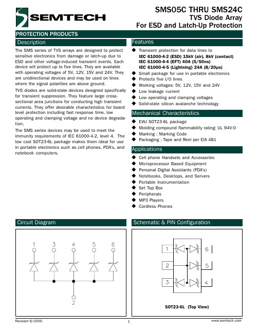
110 100
90 80 70 60 50 40 30 20 10
0 0
25
50
75
100
125
150
Ambient Temperature - TA (oC)
Clamping Voltage vs. Peak Pulse Current
Clamping Voltage - VC (V)
45
40 SMS24C
Non-Repetitive Peak Pulse Power vs. Pulse Time
10
Peak Pulse Power - PPP (kW)
1
0.1
Percent of IPP
0.01 0.1
110 100
90 80 70 60 50 40 30 20 10
0 0
1
10
100
Pulse Duration - tp (µs)
SMS15C Parameter
Reverse Stand-Off Voltage Reverse Breakdown Voltage Reverse Leakage Current Clamping Voltage Clamping Voltage Junction Capacitance
Symbol VRWM VBR IR VC VC Cj
Minimum
It = 1mA
6
VRWM = 5V, T=25°C
IPP = 5A, tp = 8/20µs
IPP = 24A, tp = 8/20µs
Between I/O Pins and Gnd
VR = 0V, f = 1MHz
Typical 325
美国MOTOROLA 压力传感器说明书

美国MOTOROLA压力传感器美国MOTOROLA公司的MPX系列硅压力传感器,主要以气压测量为主,适合用于医疗器械,气体压力控制等领域,输出数字信号。
其测量方式可分为:表压(GP)、绝压(A、AP)、差压(D、DP)型。
在宽温度范围工作时需外加补偿网络和信号调整电路。
具体型号分类而定名称:MPX2010DP 名称:MPX5700DP MPX5700GP 名称:MPX2100AP名称:MPX5500DP 名称:MPX5100AP 名称:MPX5050DP名称:MPX5010DP 名称:MPX4115AP 名称:MPX2200A 名称:MPX2200AP 名称:MPXH6115A6U 名称:MPX4250DP名称:MPX4115A 名称:MPX2202DP 名称:MPX2102AP名称:MPX2053GP 名称:MPXY8300A6U 压力传感器 名称:触力型压力传感器 FSG15N1A 名称:硅压力传感器 MPXH6115A 名称:MPX5700DP 硅压力传感器 名称:MPX53GP 硅压力传感器 名称:压力传感器FPM07 名称:轮胎压力传感器TP015 名称:轮胎压力传感器NPP301名称:Freescale 压力传感器 MPX2010DP商斯达实业传感器与智能控制分公司专门从事各种进口传感器的营销工作,代理多家欧美知名公司的产品。
涉及压力、温度、湿度、电流、液位、磁阻、霍尔、流量、称重、光纤、倾角、扭矩、气体、光电、位移、触力、红外、速度、加速度等多种产品。
广泛应用于航空航天、医疗器械(如血压计)、工业控制、冶金化工、汽车制造、教育科研等领域。
商斯达实业代理的品牌产品主要有:压 力:Kulite、ACSI、Honeywell、Entran、Gems、Dwyer、SSI、Smi、Senstronics、Intersema、Motorola、 NAIS、E+H、Fujikura、Dytran、APM称重测力:Transcell、HBM、Interface、Thamesside、Philips、Entran 温 湿 度:Honeywell、Dwyer流 量:Gems、Dwyer、Honeywell、Folwline、WorldMagnetics 液 位:Honeywell、Siccom、Gems、Dwyer、Kulite、SSI 加 速 度:Entran、Silicondesigns、Dytran 压力开关:ACSI、Gems、Dwyer、台湾矽微航空器材:TexTech 隔音材料、Honeywell 薄膜加热片、DigirayX 射线探伤仪 仪 表:Honeywell、Transcell、东辉、上润、AD、东崎商斯达实业 除代理上述产品外,还有几条传感器生产线,一条压力传感器组装线,可为用户提供各种用途的、特殊要求的配套产品。
SMS12中文资料

u EIAJ SOT23-6L package u Molding compound flammability rating: UL 94V-0 u Marking : Marking Code u Packaging : Tape and Reel per EIA 481
Applications
u Cell phone Handsets and Accessories u Microprocessor Based Equipment u Personal Digital Assistants (PDAs) and Pagers u Desktops PC and Servers u Notebook, Laptop, and Palmtop Computers u Portable Instrumentation u Peripherals u MP3 Players u Cordless Phones
Symbol Ppk IPP VPP TL TJ TSTG
Value 350 24 >25 260 (10 sec.) -55 to +125 -55 to +150
Units Watts
A kV °C °C °C
Electrical Characteristics
SMS05
Parameter
Symbol
PROTECTION PRODUCTS Applications Information
Device Connection for Protection of Four Data Lines The SMSxx is designed to protect up to four unidirectional data lines. The device is connected as follows:
SMTA5-300-55中文资料

SymbolTest ConditionsUnitValueParameterA kA I GT I TAVM I TRMS I TSM 2i t(di/dt)cr(dv/dt)cr I /I RRM DRM V RRM V DRM V RSM V TM r T V GT V GD I GD I H I L2i t-valueaverage on-state current maximum RMS on-state current surge-currentcritical rate of rise of on-state current critical rate of rise of off-state volvage off-state Leakage current reverse repeatPeak value voltage off state repeat Peak value voltage non-repetitivepeak reverse voltage on-state voltage slope resistance gate trigger voltage gate trigger current gate non-trigger voltage gate non-trigger current holding current latching currentO T =100C C T =T VJ VJMO T =25C; t =10ms C P T =T ; t =10ms VJ VJM P T =T ; V =0.67·V ;VJ VJM D DRM f =50 Hz; i =3A;GM di /dt=6A/µsG T =T; V =0.67·V ;VJ VJM D DRM gate openT =T ; V =V ; V =V VJ VJM R RRM D DRM O T =T ; 180C sine wave,VJ VJM 50 Hz; gate openT =T VJ VJMT =T ; I =800A VJ VJM TM T =T VJ VJMO T =25C; V =12V; gate open VJ D O T =25C; V =12V VJ D T =T ;V =0.67·V VJ VJM D DRM T =T ;V =0.67·V VJ VJM D DRMO T =25C; V =12V;VJ D t =20µs;i =3A;G GM di /dt=6A/µsG A 2kA ·sA/µsV/µs mA V V V Vm W V mA V mA mA mA3005204.84.311592.525010001005000-65005000-65005100-66002.352.32.53500.410350450O T =25C; V =12V VJ D Phase Control ThyristorSM TA5-300TypeV RSMV ,RRM V DRMSMT -00-SMTA5-300-52SMTA5-300-55SMTA5-300-60SMTA5-300-65A53505100530056006100660050005200550060006500O T =25C; t =10ms C P T =T ; t =10ms VJ VJM P 元器件交易网mAs Q r V TO T VJ T VJM T stg R thJ ÑF W àrecovered charge threshold voltage working junction temperaturemaximumworking junction temperature storage temperature thermal resistance; junction to case clamping force weightmaximumallowable accelerationT =T VJ VJMVOCOC OCK/W kN g 2m/s3.51.20-40...+125125-40...+1250.0451228050t gddelay time O T =25C;V =0.5·V ;VJ D DRM i =3A; di /dt=6A/µs GM G t qturn-off timeT =T ; I =I ;VJ VJM T TAVM t =200µs; di /dt=10A/µs;P R V =0.67·V ;V =100V;D DRM R dV /dt=20V/µsD µsµs2500T =T ; I =I ;di /dt=10A/µs;VJ VJM T TAVM R V =0.5·V ;V=0.8·V R RRM RM RRM R th ÑH thermal resistance; case to heatsink K/W 0.008DC , two-sided cooling two-sided coolingI [A ]T V [V]T Limiting on-state characteristic i = f (V )T T Ò = T Vj Vj max30 Array 20105210.50.210205010020050010002000500010000i[mA]GGate characteristic V=f(i)with triggering area for V = 6VG G DMaximum rated peak gate power dissipation P = f (t):GM ga - 20 W(10ms)b - 40 W(1ms)c - 60 W(0.5ms)Features:CHermetic metal case with ceramic insulator CCapsule packages for double sided cooling CInternational standard caseCAmplifying gates Typical Applications: CDC motor controlCAC motor soft starter CControlled rectifiers CAC controllers0.0010.010.11t [s]101000.010.020.030.040.050.06Z[K/W]thJCTransient thermal impedance Z = f(t)thJCDC, two-sided cooling。
178-5793中文资料
Product Catalog for related products (676 k)
Home | Company Information | Hi Voltage | Microwave | Contact Us Copyright © Teledyne Technologies Incorporated. All rights reserved. 12333 West Olympic Boulevard - Los Angeles, CA 90064
元器件交易网
Teledyne Reynolds Ltd - High Voltage Connectors, High Voltage Cable Assemblies, High Voltage Wire, High Voltage Cable, High Voltage Capacitors
Operating Voltage (KVDC) 5 5 0 8 8 8 8 8 8 8 8 8 8 0 0 0 1 2 2 2 5 5 5 5 5 5 5 0 0 0 0 r G 9 8 0 8 8 6 6 6 6 4 4 4 4 2 2 2 8 2 2 0 8 6 2 2 0 0 6 0 0 0 6 s 51/46 19/40 19/32 19/40 19/40 19/38 19/38 19/38 19/38 19/36 19/36 D 19/36 19/34 19/34 D 19/30 19/34 19/34 19/32 19/40 19/38 19/34 19/34 19/32 19/32 19/29 19/32 19/32 19/32 19/29 C C C C C C C C C C C Tin/Ni C C C Tin/Ni C C C C C C C C C C C C C C C r g Ø mm 0.35 0.40 1.01 0.40 0.40 0.50 0.50 0.50 0.50 0.64 0.64 0.51 0.64 0.80 0.80 0.64 1.27 0.80 0.80 1.01 0.40 0.50 0.80 0.80 1.01 1.01 1.43 1.01 1.01 1.01 1.43 mm in 0.64 / 0.025 1.02 / 0.040 1.52 / 0.060 1.02 / 0.040 1.02 / 0.040 1.14 / 0.045 1.14 / 0.045 1.27 / 0.050 1.27 / 0.050 1.27 / 0.050 1.27 / 0.050 1.27 / 0.050 1.52 / 0.060 1.52 / 0.060 1.52 / 0.060 1.52 / 0.060 2.03 / 0.080 2.03 / 0.080 2.03 / 0.080 2.29 / 0.090 1.91 / 0.075 2.03 / 0.080 2.03 / 0.080 2.54 / 0.100 2.03 / 0.080 2.03 / 0.080 2.54 / 0.100 2.54 / 0.100 2.54 / 0.100 3.81 / 0.150 4.57 / 0.180 Ø Over insulation
SCI7633M资料
SCI7630M Series1元器件交易网 SCI7630M Series元器件交易网SCI7630M Series元器件交易网 SCI7630M Series元器件交易网SCI7630M SeriesSCI7630M Series6ELECTRONIC DEVICES MARKETING DIVISIONIC Marketing & Engineering GroupED International Marketing Department I (Europe & U.S.A.)421-8, Hino, Hino-shi, Tokyo 191-8501, JAPANPhone : +81-(0)42-587-5812 FAX : +81-(0)42-587-5564ED International Marketing Department II (Asia)421-8, Hino, Hino-shi, Tokyo 191-8501, JAPANPhone : +81-(0)42-587-5814 FAX : +81-(0)42-587-5110NOTICE:No part of this material may be reproduced or duplicated in any form or by any means without the written permission of Seiko Epson. Seiko Epson reserves the right to make changes to this material without notice. Seiko Epson does not assume any liability of any kind arising out of any inaccuracies contained in this material or due to its application or use in any product or circuit and, further, there is no representation that this material is applicable to products requiring high level reliability, such as, medical products. Moreover, no license to any intellectual property rights is granted by implication or otherwise, and there is no representation or warranty that anything made in accordance with this material will be free from any patent or copyright infringement of a third party. This material or portions thereof may contain technology or the subject relating to strategic products under the control of the Foreign Exchange and Foreign Trade Law of Japan and may require an export license from the Ministry of International Trade and Industry or other approval from another government agency.© Seiko Epson Corporation 2000 All right reserved.All other product names mentioned herein are trademarks and/or registered trademarks of their respective companies.First issue February, 2000Printed in Japan Ts。
JR5S5-2000中文资料

FEATURES● 10 Watts Output Power ● High Efficiency up to 86% ● Fixed Switching Frequency ● Six-Sided Continuous Shield ● 2:1 Wide Input Voltage Range ● Standard 2 x 1 x 0.4 inch Package ● International Safety Standard Approval● Options: Add suffix “-I” for Extended Operating Temperature RangeSPECIFICATIONS:JR SeriesAll specifications apply @ 25°C ambient unless otherwise notedINPUT SPECIFICATIONS Input Voltage Range............5V nominal input.........................4.5 - 9VDC 12V nominal input........................9 - 18VDC 24V nominal input......................18 - 36VDC 48V nominal input......................36 - 75VDCInput Filter.......................................................................................Pi TypeInput Surge Voltage (100ms max).......5V input .............................15VDC 12V input ...........................36VDC24V input ...........................50VDC48V input .........................100VDCInput Reflected Ripple Current (See Note 2)...............................30mAp-p (nominal Vin and full load)Start Up Time (nominal Vin and constant resistive load).............20ms typ.Remote ON/OFF (Option) (See Note 3)(Positive Logic)...............DC-DC ON.............Open or 3.5V < Vr < 12V DC-DC OFF.............Short or 0V < Vr < 1.2V (Negative Logic).............DC-DC ON...............Short or 0V < Vr < 1.2V DC-DC OFF...........Open or 3.5V < Vr < 12VRemote Off Input Current (nominal Vin)............................................20mAOUTPUT SPECIFICATIONSOutput Voltage..............................................................................see tableVoltage Accuracy (nominal Vin and full load) (1)Output Current..............................................................................see tableOutput Power........................................................................10 watts max.Line Regulation (LL to HL at FL).......................................................±0.2%Load Regulation (10% - 100 % FL)..............Single Output..............±0.5%Dual Output (1)Cross Regulation (Dual) (Asymmetrical load 25% / 100% FL) (5)Minimum Load (See Note 1) ..............................................10% of full loadRipple/Noise (20 MHz BW)......................Single Output..............50mVp-p Dual Output ................75mVp-p Temperature Coefficient .................................................±0.02% / °C max.Transient Response Recovery Time (25% load step).......................250usPROTECTION SPECIFICATIONSOver Voltage Protection.................3.3V output..................................3.9V(zener diode clamp) 5V output..................................6.2V 12V output...................................15V 15V output.. (18V)Over Load Protection (% of full load at nominal input)..............150% max.Short Circuit Protection....................................Hiccup, automatic recoveryGENERAL SPECIFICATIONSEfficiency........................................................................................see tableSwitching Frequency.................................................................300KHz typ.Isolation Voltage (Input to Output).........................................1600VDC min.Isolation Resistance (109)ohms min.Isolation Capacitance................................................................300pF max.ENVIRONMENTAL SPECIFICATIONSOperating Temperature (See derating curves) Standard............................................... -25°C ~ +85°C (with derating) “I” (See Note 5)........................................-40°C ~ +85°C (no derating) (except for 5V input models) Storage Temperature ..........................................................-55°C ~ +105°CMaximum Case Temperature.............................................................100°CRelative Humidity...................................................................5% to 95% RHThermal Impedance (See Note 6) Natural Convection.............................................................12°C / Watt Natural Convection with Heat-Sink.....................................10°C / WattThermal Shock .................................................................... MIL-STD-810DVibration ................................10~55Hz, 10G, 30 minutes along X, Y, and ZMTBF (See Note 4)..........................................................1.976 x 106hoursPHYSICAL SPECIFICATIONSWeight .....................................................................................27g (0.95 oz)Dimensions....................... 2.0 x 1.0 x 0.40 inches (50.8 x 25.4 x 10.2 mm) Case Material ..............................................................Nickel-coated copperBase Material...................................................Non-conductive black plastic Potting material..................................................................Epoxy (UL94-V0)Shielding.........................................................................................six-sidedSAFETY & EMCApprovals and Standards..................IEC60950-1, UL60950-1, EN60950-1(except for 5V input models)Conducted Emissions.........EN55022..............................................Class ARadiated Emissions............EN55022..............................................Class AEN55022 (See Note 7).........................Class BESD....................................EN61000-4-2.............................Perf. Criteria BRadiated Immunity..............EN61000-4-3.............................Perf. Criteria AFast Transient.....................EN61000-4-4.............................Perf. Criteria BSurge..................................EN61000-4-5.............................Perf. Criteria BConducted Immunity...........EN61000-4-6.............................Perf. Criteria ADue to advances in technology, specifications subject to change without noticeUL TUV CBCE MARKOUTPUT VOLTAGE / CURRENT RATING CHARTModel NumberInput Range Output Voltage Output CurrentOutput Ripple & Noise Input Current (8) Efficiency (9)Capacitor (10)Load maxJR5S5-2000 5 VDC 2000mA 50mVp-p 2500mA 79% 7900µFJR5S12-830 12 VDC 830mA 50mVp-p 2350mA 82% 2200µFJR5S15-660 15 VDC 670mA 50mVp-p 2348mA 82% 1470µF JR5D5-1000 ± 5 VDC ±1000mA 75mVp-p 2461mA 80% ±5060µFJR5D12-420 ± 12 VDC ±416mA 75mVp-p 2503mA 80% ±1034µF JR5D15-330 5 VDC (4.5 – 9 VDC) ± 15 VDC ±333mA 75mVp-p 2393mA 81% ±660µF JR12S33-2000 3.3 VDC 2000mA 50mVp-p 724mA 80% 6800µF JR12S5-2000 5 VDC 2000mA 50mVp-p 1082mA 81% 4700µF JR12S12-830 12 VDC 830mA 50mVp-p 1037mA 84% 690µF JR12S15-660 15 VDC 670mA 50mVp-p 1046mA 84% 470µF JR12D5-1000 ± 5 VDC ±1000mA 75mVp-p 1042mA 84% ±680µFJR12D12-420 ± 12 VDC ±416mA 75mVp-p 1053mA 83% ±330µF JR12D15-330 12 VDC (9 – 18 VDC)± 15 VDC ±333mA 75mVp-p 1041mA 84% ±110µF JR24S33-2000 3.3 VDC 2000mA 50mVp-p 362mA 80% 6800µF JR24S5-2000 5 VDC 2000mA 50mVp-p 534mA 82% 4700µF JR24S12-830 12 VDC 830mA 50mVp-p 519mA 84% 690µF JR24S15-660 15 VDC 670mA 50mVp-p 523mA 84% 470µF JR24D5-1000 ± 5 VDC ±1000mA 75mVp-p 527mA 83% ±680µFJR24D12-420 ± 12 VDC ±416mA 75mVp-p 513mA 85% ±330µFJR24D15-33024 VDC (18 – 36 VDC)± 15 VDC ±333mA 75mVp-p 520mA 84% ±110µF JR48S33-2000 3.3 VDC 2000mA 50mVp-p 181mA 80% 6800µF JR48S5-2000 5 VDC 2000mA 50mVp-p 260mA 84% 4700µF JR48S12-830 12 VDC 830mA 50mVp-p 253mA 86% 690µF JR48S15-660 15 VDC 670mA 50mVp-p 252mA 87% 470µF JR48D5-1000 ± 5 VDC ±1000mA 75mVp-p 260mA 84% ±680µFJR48D12-420 ± 12 VDC ±416mA 75mVp-p 254mA 86% ±330µF JR48D15-330 48 VDC (36 – 75 VDC)± 15 VDC ±333mA 75mVp-p 256mA 85% ±110µFNOTES1. The JR Series requires a minimum 10% loading on the output to maintain specified regulation. Operation under no load condition will not damage these devices, however, they may not meet all listed specifications.2. Please add an external filter at converter input terminals when measuring input reflected ripple current (See Figure 1). L: Simulated source impedance of 12uH C: Nippon chemi-con KMF Series 47uF/100V.3. The ON/OFF control pin voltage is referenced to –Vin.To order negative logic On/Off control add the suffix “R” (Ex: JR12S5-2000R).4. BELLCORE TR-NWT-000332. Case 1: 50% Stress, Temperature at 40ºC. (Ground fixed and controlled environment).5. “I” Version is more efficient; therefore, it can be operated over a more extensive temperature range than the standard version. Please add the suffix “-I” for industrial grade temperature range models.6. Heat sink is optional, please consult factory for ordering details.7. The JR Series meets 55022 class B with external components connected before the input pin to the converter. 8. Maximum value at nominal input voltage and full load of standard type. 9. Typical value at nominal input voltage and no load. 10. Tested at minimum Vin and constant resistive load.Figure 1DERATING CURVES & EFFICIENCY GRAPHSMECHANICAL DRAWINGUNIT: inches (mm)PIN CONNECTIONPIN SINGLE DUAL1 +INPUT +INPUT2 -INPUT -INPUT3 +OUTPUT +OUTPUTPIN COMMON4 NO5 -OUTPUT -OUTPUT6 CTRL (Option) CTRL (Option)1. All dimensions in Inches (mm)Tolerance: X.XX±0.02 (X.X±0.5)2. Pin pitch tolerance ±0.014 (0.35)。
瑞萨MCU型号速查手册

SSOP-20 SOP-20
家电、OA设备、民用设备
M34508G4H-XXXFP/GP
○○
4509
M34509G4FP M34509G4-XXXFP
M34509G4HFP M34509G4H-XXXFP
--
4096W
256W
6MHz/ 1.8V~5.6V
0.5us @6MHz
18 - - ○ -
10位×6
M37546G4GP/HP/SP M37546G4-XXXGP/HP/SP
8K 16K
384
8MHz/ 1.8~5.5V
0.25us @8MHz
25 - - ○ ○ ○ ○ 10位×6
-
2 2 ○ ○ ○ ○ - - ○ ○ ○ - - 12 -20~85
512
SDIP-32 LQFP-32
WQFN-36
2K
60K
2.5K
照相机、音频设备、家电、民用设备
3850A
M38503G4AFP/SP M38503G4A-XXXFP/SP
16K
512
12.5MHz/ 1.8~5.5V
0.32us @12.5MHz
34
-
○
-
-
-
-
10位×9
-
4 - - - ○ ○ - - ○ ○ ○ - - 6 -20~85
SDIP-42 SSOP-42
75
芯片封装说明
78
QzROM
720、740工具
低功耗
R8C族及工具
M16C
R32C
M16C族工具 SuperH族及工具 安全MCU
78K
V850
78K、V850工具 芯片封装说明
明微SM7630最新方案说明书
-8-
Datasheet Symbol Min A B C D F G J K M P R 0.19 0.05 0° 5.80 0.25 9.80 3.80 1.35 0.25 0.40 1.27BSC 0.25 0.25 8° 6.30 0.50 Millimenters Max 10.16 4.04 1.80 0.510 1.27
-3-
SM7630 BOOST_PFC+BUCK 组合恒流控制器 功能表述
SM7630 是应用于中功率非隔离 LED 照明的高性能升压 PFC 和 BUCK 恒流组合控制芯片,可以在全电压输 入范围内实现高精度,高 PF 恒流输出,精度小于±3%,同时解决了单级 PFC 的频闪缺陷。 SM7630 主要适用于高亮的 BOOST+BUCK LED 驱动器。可以轻松实现 PF >0.98,THD<10%的应用场合。另外, SM7630 具有 LED 输出开/短路保护功能。 内部稳压器 通过 HVDD 输入端提供给内部电路以及外部电路的供电电源。当对 GATE 栅电容充电时,电源的电流波动 较大,使得电源产生较大的波动,为了稳定电源在 HVDD 端外接一低 ESR 的电容。 PWM(升压)开启控制 芯片通过检测电感电流将近过零来控制 MOSFET 开关。电感电流大小可通过 CS 电压来判断,当电感电流 下降时,CS 管脚电压相应的也会下降,当 FB 管脚电压小于芯片内部设定值时,实现 MOSFET 的开启。 恒流精度控制(BUCK) SM7630 芯片的二级 BUCK 恒流部分要实现高精度的恒流控制,应用系统工作在临界(BCM)下。芯片通过检 测辅助绕组的电压,来控制输出电流。输出电流仅由峰值电流控制:
Io 1 / 2 I P
5082-563G-0K300资料

DescriptionThese slim font seven segment displays incorporate a new slim font character design. This slim font features narrow width,specially mitered segments to give a fuller appearance to the illuminated character. Faces of these displays are painted aneutral gray for enhanced on/off contrast.Agilent HDSP-301x/303x Series HDSP-561x/563x Series 10 mm and 13 mm Slim Font Seven Segment DisplaysData SheetFeatures•Excellent appearance •Slim font design •Mitered corners, evenly illuminated segments•Gray face for optimum on/off contrast •Choice of colors: HER, green,yellow, and AlGaAs •Choice of character size: 10 mm and 13 mm •Characterized for luminous intensityDevices HER Green Yellow AlGaAs HDSP-HDSP-HDSP-HDSP-Description301E 301G 301Y 301A Common Anode, 10 mm Display 303E 303G 303Y 303A Common Cathode, 10 mm Display 561E 561G 561Y 561A Common Anode, 13 mm Display 563E563G563Y563ACommon Cathode, 13 mm DisplayAll devices are available in either common anode or commoncathode configuration with righthand decimal point.Part Numbering System5082- x xx x-x x x xxHDSP- x xx x-x x x xxMechanical Options[1]00: No Mechanical OptionColor Bin Options[1,2]0: No Color Bin LimitationMaximum Intensity Bin[1,2]0: No Maximum Intensity Bin LimitationMinimum Intensity Bin[1,2]0: No Minimum Intensity Bin LimitationDevice Configuration/Color[1]A: AlGaAs RedE: High Efficiency RedG: GreenY: YellowDevice Specific Configuration[1]Refer to Respective Data SheetPackage[1]Refer to Respective Data SheetNotes:1. For codes not listed in the figure above, please refer to the respective data sheet or contact your nearest Agilent representativefor details.2. Bin options refer to shippable bins for a part-number. Color and Intensity Binbs are typically restricted to 1 bin per tube(exceptions may apply). Please refer to respective data sheet for specific bin limit information.Pin Function1G2F3Common A/C 4E5D6DP7C8Common A/C 9B10A7.006.40NOTE: QDSP-399G DOES NOT HAVE PIN 6.COUNTRY TOP SIDEFRONT VIEW RIGHT SIDE0.30 ± 0.05(0.012)6.001.85Pin Function 1E 2D3Common A/C 4C 5DP 6B 7A8Common A/C 9F 10G0.29 ± 0.08 TYP.(0.011)12345(0.023)(0.141)(0.100)NOTES:1. ALL DIMENSIONS ARE IN MILLIMETERS (INCHES).2. UNLESS OTHERWISE STATED, TOLERANCES ARE ±0.25 mm.Absolute Maximum RatingsDescription HER Green Yellow AlGaAs Units Average Power per Segment or DP10510510537mW Peak Forward Current per Segment or DP90909045mA DC Forward Current per Segment or DP30303015mA Operating Temperature Range–40 to +80–40 to +80–40 to +80–20 to +80˚C Storage Temperature Range–40 to +80–40 to +80–40 to +80–40 to +80˚C Reverse Voltage per Segment or DP5555V Wavesoldering Temperature for 3 Seconds250250250250˚C 1.59 mm below bodyNotes:1.Derate above 33˚C at 0.34 mA/˚C for HER.2.Derate above 27˚C at 0.32 mA/˚C for Green.3.Derate above 30˚C at 0.33 mA/˚C for Yellow.4.Derate above 60˚C at 0.25 mA/˚C for AlGaAs.Electrical/Optical Characteristics at T A = 25˚CHERDeviceSeriesHDSP-Parameter Symbol Min.Typ.Max.Units Test Conditions 301/303E Luminous Intensity/Segment I V 1.251 2.000mcd I F = 10 mA (Digit Average)Forward Voltage/Segment V F 1.90 2.50V I F = 20 mAor DPPeak WavelengthλPEAK635nm I F = 20 mADominant Wavelengthλd625nm I F = 20 mAReverse Current I R100µA V R = 5 VThermal Resistance LED RθJ–PIN351.5˚C/W/Seg.Junction-to-PinHERDeviceSeriesHDSP-Parameter Symbol Min.Typ.Max.Units Test Conditions 561/563E Luminous Intensity/Segment I V 2.001 3.526mcd I F = 10 mA (Digit Average)Forward Voltage/Segment V F 1.90 2.50V I F = 20 mAor DPPeak WavelengthλPEAK635nm I F = 20 mADominant Wavelengthλd625nm I F = 20 mAReverse Current I R100µA V R = 5 VThermal Resistance LED RθJ–PIN351.5˚C/W/Seg.Junction-to-PinDeviceSeriesHDSP-Parameter Symbol Min.Typ.Max.Units Test Conditions 301/303G Luminous Intensity/Segment I V 2.001 3.200mcd I F = 10 mA (digit average)Forward Voltage/Segment V F 2.25 2.50V I F = 20 mAor DPPeak WavelengthλPEAK568nm I F = 20 mADominant Wavelengthλd573nm I F = 20 mAReverse Current I R100µA V R = 5 VThermal Resistance LED RθJ–PIN351.5˚C/W/Seg.Junction-to-PinGreenDeviceSeriesHDSP-Parameter Symbol Min.Typ.Max.Units Test Conditions 561/563G Luminous Intensity/Segment I V 3.201 5.601mcd I F = 10 mA (Digit Average)Forward Voltage/Segment V F 2.25 2.50V I F = 20 mAor DPPeak WavelengthλPEAK568nm I F = 20 mADominant Wavelengthλd573nm I F = 20 mAReverse Current I R100µA V R = 5 VThermal Resistance LED RθJ–PIN351.5˚C/W/Seg.Junction-to-PinYellowDeviceSeriesHDSP-Parameter Symbol Min.Typ.Max.Units Test Conditions 301/303Y Luminous Intensity/Segment I V 1.251 2.000mcd I F = 10 mA (Digit Average)Forward Voltage/Segment V F 2.15 2.50V I F = 20 mAor DPPeak WavelengthλPEAK589nm I F = 20 mADominant Wavelengthλd590nm I F = 20 mAReverse Current I R100µA V R = 5 VThermal Resistance LED RθJ–PIN351.5˚C/W/Seg.Junction-to-PinDeviceSeriesHDSP-Parameter Symbol Min.Typ.Max.Units Test Conditions 561/563Y Luminous Intensity/Segment I V 2.00 3.526mcd I F = 10 mA (Digit Average)Forward Voltage/Segment V F 2.15 2.50V I F = 20 mAor DPPeak WavelengthλPEAK589nm I F = 20 mADominant Wavelengthλd590nm I F = 20 mAReverse Current I R100µA V R = 5 VThermal Resistance LED RθJ–PIN351.5˚C/W/Seg.Junction-to-PinNotes:1.Typical specification for reference only. Do not exceed absolute maximum ratings.2.The dominant wavelength, λ, is derived from the CIE chromaticity diagram and is that single wavelength which defines the color of the device.AlGaAsDeviceSeriesHDSP-Parameter Symbol Min.Typ.Max.Units Test Conditions 301/303A Luminous Intensity/Segment I V0.3200.505mcd I F = 1 mA (Digit Average)Forward Voltage/Segment V F 1.80 2.20V I F = 20 mAor DPPeak WavelengthλPEAK660nm I F = 20 mADominant Wavelengthλd643nm I F = 20 mAReverse Current I R100µA V R = 5 VThermal Resistance LED RθJ–PIN351.5˚C/W/Seg.Junction-to-PinAlGaAsDeviceSeriesHDSP-Parameter Symbol Min.Typ.Max.Units Test Conditions 561/563A Luminous Intensity/Segment I V0.5060.878mcd I F = 1 mA (Digit Average)Forward Voltage/Segment V F 1.80 2.20V I F = 20 mAor DPPeak WavelengthλPEAK660nm I F = 20 mADominant Wavelengthλd643nm I F = 20 mAReverse Current I R100µA V R = 5 VThermal Resistance LED RθJ–PIN351.5˚C/W/Seg.Junction-to-PinNotes:1.Typical specification for reference only. Do not exceed absolute maximum ratings.2.The dominant wavelength, λ, is derived from the CIE chromaticity diagram and is that single wavelength which defines the color of the device.HDSP-301E/303E/561E/563EIV Bin Category Min.Max.I 1.100 2.200K 1.800 3.600HDSP-561Y/563Y IV Bin Category Min.Max.K 1.800 3.600L 2.8005.600HDSP-301Y/303YIV Bin Category Min.Max.I 1.100 2.200K 1.8003.600HDSP-301A/303A/561A/563AIV Bin Category Min.Max.F 0.2800.560G 0.4500.900HDSP-301G/303G/561G/563GIV Bin Category Min.Max.K 1.800 3.600L 2.800 5.600Intensity Bin Limits (mcd)GreenYellowHERAlGaAs RedDominant Wavelength (nm)ColorBin Min.Max.Green 3570.00574.504567.00571.50Yellow2586.50590.003584.00587.50Color CategoriesNote:1. All categories are established for classification of products.Products may not be available in all categories. Please contact your Agilent representatives for further clarification/information.YellowFigure 1. Maximum allowable DC current vs.ambient temperature.Figure 2. Forward current vs. forward voltage.Figure 3. Relative luminous intensity vs. DC forward current.HDSP-301x/303x SeriesContrast EnhancementFor information on contrast enhancement, please see Application Note 1015.Soldering/CleaningCleaning agents from the ketone family (acetone, methyl ethyl ketone, etc.) and from thechlorinated hydrocarbon family (methylene chloride,Figure 4. Maximum allowable DC current vs.ambient temperature.Figure 5. Forward current vs. forward voltage.Figure 6. Relative luminous intensity vs. DC forward current.HDSP-561x/563x SeriesI D C – M A X I M U M D C C U R R E N T P E R S E G M E N T – m AT A – AMBIENT TEMPERATURE – °CI F – F O R W A R D C U R R E N TP E R S E G M E N T – m AV F – FORWARD VOLTAGE – V I D C – M A X I M U M D C C U R R E N T P E R S E G M E N T – m AT A – AMBIENT TEMPERATURE – °CI F – F O R W A R D C U R R E N TP E R S E G M E N T – m AV F – FORWARD VOLTAGE – V trichloroethylene, carbon tetrachloride, etc.) are notrecommended for cleaning LED parts. All of these varioussolvents attack or dissolve the encapsulating epoxies used to form the package of plastic LED parts.For information on soldering LEDs, please refer to Application Note 1027.R E L A T I V E L U M I N O U S I N T E N S I T Y (N O R M A L I Z E D T O 1 A T 5 m A F O R H E R A N D Y E L L O W A N D T O 1 A T 10 m A F O R G R E E N )I F – DC FORWARD CURRENT – mA12682410R E L A T I V E L U M I N O U S I N T E N S I T Y (N O R M A L I Z E D T O 1 A T 5 m A F O R H E R A N D Y E L L O W A N D T O 1 A T 10 m A F O R G R E E N )I F – DC FORWARD CURRENT – mA/semiconduc-torsFor product information and a complete list of distributors, please go to our web site.For technical assistance call:Americas/Canada: +1 (800) 235-0312 or (916) 788-6763Europe: +49 (0) 6441 92460China: 10800 650 0017Hong Kong: (+65) 6756 2394India, Australia, New Zealand: (+65) 6755 1939 Japan: (+81 3) 3335-8152(Domestic/ International), or 0120-61-1280(Domestic Only) Korea: (+65) 6755 1989Singapore, Malaysia, Vietnam, Thailand, Philippines, Indonesia: (+65) 6755 2044 Taiwan: (+65) 6755 1843Data subject to change.Obsoletes 5980-2919ENJuly 11, 20045988-4352EN。
大龙移液器中文说明书
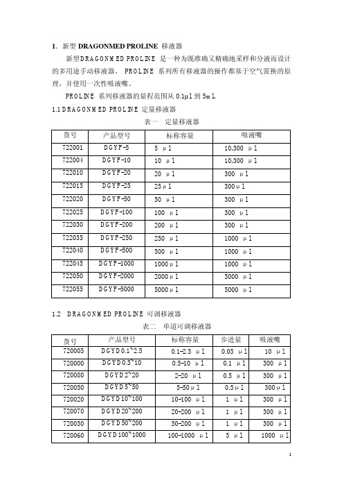
表一 定量移液器
货号
产品型号
标称容量
吸液嘴
722001
DGYF-5
5 μl
10,300 μl
722004
DGYF-10
10 μl
10,300 μl
722010
DGYF-20
20 μl
300 μl
722015
DGYF-25
25μl
300μl
722020
DGYF-50
50 μl
300 μl
722025
DGYF-100
开锁定装置; 3. 取下吸液嘴推出轴; 4. 向下按住吸液嘴推出器,将 300µl 推出轴的锁销插
入推出杆上的小孔; 5. 松开吸液嘴推出器,再上下按动,看是否活动自如
4
5.4 防护滤芯 PROLINE 单道移液器(>10µl)的新型吸液嘴连件可选配置换型滤芯。滤芯
能够防止液体或气溶胶进入移液器。有两种滤芯供选:标准型和加强型(参考表 1.1 中的目录号)。加强型滤芯能彻底隔绝液体和气溶胶。而且滤芯并不影响移液 器校准。(图 8)
在吸液嘴中而不被转移 4. 多余液体随吸液嘴丢弃或返回原来容器
7. 储放 移液器如不使用,建议将它竖直挂在移液器架上。见第 3 章,安装移液器架钩。
8. 性能测试及重新校准 每支移液器出厂前都经过了测试,出具有检测证书。 注意:移液器性能仅在与 DRAGONMED PROLINE 吸液嘴配套使用时得以
100 μl
300 μl
722030
DGYF-200
200 μl
300 μl
722035
DGYF-250
250 μl
1000 μl
722040
SAB-C517A中文资料

On-Chip Emulation Support Module
Oscillator Watchdog
Watchdog Timer T0 T2 T1 10-Bit A/D Converter
XRAM 2K x 8
RAM 256 x 8
Port 0 Port 1
I/O I/O I/O I/O I/O
Power Saving Modes
• • • •
• • •
Ordering Information The ordering code for Siemens microcontrollers provides an exact reference to the required product. This ordering code identifies:
I/O
I/O
MCA03317
Figure 1 C517A Functional Units
Semiconductor Group
1
元器件交易网
C517A
Features (continued) :
• Two full duplex serial interfaces (USART) •
– 500 ns instruction cycle at 24 MHz operation Superset of the 8051 architecture with 8 datapointers On-chip emulation support logic (Enhanced Hooks Technology TM) 32K byte on-chip ROM (with optional ROM protection) – alternatively up to 64K byte external program memory Up to 64K byte external data memory 256 byte on-chip RAM Additional 2K byte on-chip RAM (XRAM) Seven 8-bit parallel I/O ports Two input ports for analog/digital input (further features are on next page)
SMS模块用户手册说明书

SMS MODEM User Manual CHINA SKYLINE TELECOM CO.,LTDmodel channels GSM3G volume weightSMS MODEM88M35UC15-A UC15-E L:230mm*W:130mm*H:150mm3.5kgSMS MODEM1616M35UC15-A UC15-E L:430mm*W:130mm*H:150mm6kgSMS MODEM3232M35UC15-A UC15-E L:260mm*170mm*150mm8.5kgSMS MODEM6464M35UC15-A UC15-E L:520mm*W:430mm*H:150mm15kgRemark:M35:GSM:850/900/1800/1900MHZUC15-A:GSM:850/900/1800/1900MHZ UMTS:850/1900MHZ UC15-E:GSM:900/1800MHZ UMTS:900/2100MHZ Operating Temperature:-20°C-+55°CStorage temperature:-25°C-+70°CSms modem8Sms modem16Sms modem32Sms modem64Specifications:1.Connect with the Computer through USB line for USB typeB Interface(Optional)3.Can send and receive SMS in bulk4.Can dial the number.5.Industrial Chassis,Elegant Appearance design.6.support Windows XP,Windows7,Linux,Unix OS etc.7.Support AT command8.Support HTTP SMTP protocol9.Baud rate:115200bits/s10.Automatic baud rate:from2400to19200bits/s11.GPRS compatible12.SMA antenna interface13.SMS:support MT,MO,CB,Text and PDU mode14.SIM interface:8/16/32/64SIM cards slotSMS MODEM Guidance:1.Install SMSCaster like common software and close it after installing successfully2.Connect the GSM MODEM to computer correctly,and then there will be a prompt from computer to install driver.3.Select the driver path for every port,it will install automatically.4.After completing the driver installation,starting SMSCaster program,all ports will be found.PS:If the driver is installed unsuccessful,open Device Manager of computer.a,Find all the unusable ports in"Universal Serial Bus controllers".b,Right Click on every port and select"Update Driver Software"–select"Browse my computer for driver software.C,Select the driver in the right path and click“next”d,After completing the driver installation,all ports will be found.How to change IMEI:1.Register your sim cards;Fine COM porte PuTTY login in COM portmand:1.input ate1enter,this is display command2.Change IMEI‘s command:IMEI(how to change the module imei(1)use putty to login the module(2)input the at command ATE1to echo display(3)AT+EGMR=1,7,"359231033480797"this at command will change the module imei to359231033480797,and plz notice that you have to use the correct imei number if not the imei will be changed back to factory after reboot.)How to use SMSCaster:1,open the smscaster,click the Phone,then update All,then you can check how many ports can work,if some ports not shows proper,then you should check the simcards or change another simcards,when you change simcards,you shouldshutdown the module,when insert simcards,then start it.pose for send sms,you can input receiver number in To Numbers if you just want to send few numbers,then input the content,when you finish,then press Send to Outbox,the sms will be sent to Outbox,press the Outbox,then you can see the detail sms list,then press the Send,they will be sent out(you should firstly choose the ports which you want to send sms).3,when there are lots of contact,then you can import the list from the CSVfile,File>Import ContactsIt will show the Import Contacts Wizard,press Browse to choose the file which you want to import,then NextIt show you which row you want to start,then Next:Then it will show the Arrange Fields and Columns.then Next:Import contacts succeeded,and show you how many contacts imported,DoneYou can see the contact list if you import succeed.If you want send same sms to all the contact,you can select All Contacts in To Group.then input the contact(you should choose the port which you want to send sms firstly before you send sms).And you can set the group,press Group>Edit.then you can see it,you can add thenumber to the new group from the number which you import contacts list.You can set pause time when one sms send.Make sure the GSM Modem have been connected to computer correctly,if that, all the ports can be found in SMSCaster,and you can set each port(SIM card)as adesignated queue or default.When you finish all these Settings,you can send text messages as your will:You can find all the messages which will be send by different queues(SIM cards) in outbox:Sms modem user manual21。
W005M_06中文资料

W005M – W10M1.5A SINGLE-PHASE BRIDGE RECTIFIERRecognized Mechanical DataCase: WOB, Molded Plastic Terminals: Plated Leads Solderable per Maximum Ratings and Electrical Characteristics @T A =25°C unless otherwise specifiedSingle Phase, half wave, 60Hz, resistive or inductive load.For capacitive load, derate current by 20%.CharacteristicSymbol W005M W01MW02MW04MW06MW08MW10MUnitPeak Repetitive Reverse Voltage Working Peak Reverse Voltage DC Blocking Voltage V RRMV RWM V R 501002004006008001000V RMS Reverse VoltageV R(RMS)3570140280420560700V Average Rectified Output Current @T A = 50°C (Note 1)I O1.5ANon-Repetitive Peak Forward Surge Current 8.3ms Single half sine-wave superimposed on rated load (JEDEC Method)I FSM 50A Forward Voltage (per element) @I F = 1.5A V FM 1.0V Peak Reverse Current @T A = 25°C At Rated DC Blocking Voltage @T A = 100°C I RM 5.0500µA Operating Temperature Range T j -55 to +125°C Storage Temperature RangeT STG-55 to +150°CNote: 1. Leads maintained at ambient temperature at a distance of 9.5mm from the case.WTE0.010.11.0100.20.6 1.0 1.4I ,I N S T A N T A N E O U S F O R W A R D C U R R E N T (A )F V ,INSTANTANEOUS FORWARD VOLTAGE (V)Fig.2Typical Forward Characteristics , per elementF 01020304050110100I ,P E A K F O R W A R D S U R G E C U R R E N T (A )F S M NUMBER OF CYCLES AT 60Hz Fig.3Max Non-Repetitive Surge Current110100110100C ,J U N C T I O N C A P A C I T A N C E (p F )j V ,REVERSE VOLTAGE (V)Fig.4Typical Junction CapacitanceR 00.51.01.50255010012515075I ,A V E R A G E F O R W A R D C U R R E N T (A )F T ,AMBIENT TEMPERATURE (°C)Fig.1Forward Current Derating CurveAMARKING INFORMATIONWxxMORDERING INFORMATIONProduct No.Package TypeShipping QuantityW005M Round Bridge 1000 Units/Box W01M Round Bridge 1000 Units/Box W02M Round Bridge 1000 Units/Box W04M Round Bridge 1000 Units/Box W06M Round Bridge 1000 Units/Box W08M Round Bridge 1000 Units/Box W10MRound Bridge1000 Units/Box1. Shipping quantity given is for minimum packing quantity only. For minimum order quantity, please consult the Sales Department.2.To order Lead Free version (with Lead Free finish), add “-LF” suffix to part number above. For example, W005M-LF.Won-Top Electronics Co., Ltd (WTE) has checked all information carefully and believes it to be correct and accurate. However, WTE cannot assume any responsibility for inaccuracies. Furthermore, this information does not give the purchaser of semiconductor devices any license under patent rights to manufacturer. WTE reserves the right to change any or all information herein without further notice.WARNING : DO NOT USE IN LIFE SUPPORT EQUIPMENT. WTE power semiconductor products are not authorized for use as critical components in life support devices or systems without the express written approval.We power your everyday.Won-Top Electronics Co., Ltd.No. 44 Yu Kang North 3rd Road, Chine Chen Dist., Kaohsiung, Taiwan Phone: 886-7-822-5408 or 886-7-822-5410Fax: 886-7-822-5417Email: sales@Internet: 。
海天注塑机器操作说明书
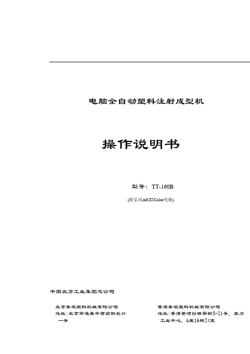
电脑全自动塑料注射成型机操作说明书型号: TT-160B(配弘讯A62I5Color电脑)中国北方工业集团总公司北京泰坦塑料机械有限公司地址:北京市通县半壁店街北口一号香港泰坦塑料机械有限公司地址:香港荃湾白田霸街5-21号,嘉力工业中心,A座16楼24室BTT北京泰坦塑料机械有限公司TT-160C(A62I5Color)2言前感谢阁下使用泰坦注塑机!泰坦系列电脑全自动塑料注射成型机,用于热塑性塑料的成型加工,其工艺过程是用一整套专用的塑料成型模具安装在注塑机锁模部分的定模板与动模板之间,经过高压锁模后,由射台部分注入高压的经加热、塑化过的塑料,经过快速冷却后形成塑料制品。
泰坦注塑机外形美观、操作方便、维修简单、生产效率高能很好地满足贵公司的生产要求。
为协助贵公司能更快、更好地使用我们产品的先进功能,本说明书将向您提供非常详细的技术资料。
贵公司如对我们的产品有任何不解之处,我们非常愿意为阁下一一解答。
祝阁下生意兴隆!出厂编号:出厂日期:2007年5月BTT北京泰坦塑料机械有限公司TT-160C(A62I5Color)3目录1安全性说明 (1)不安全的因素........................................................................ (1)安全规则........................................................................ (1)本机所具备的安全设施........................................................................ (2)警告标志说明........................................................................ (2)2技术参数 (3)代号说明........................................................................ (3)动力及其它部分........................................................................ (3)锁模部分........................................................................ (3)射台部分........................................................................ (3)3机器的安装 (4)机器的起吊........................................................................ (4)机器的安装地基图........................................................................ (4)校水平及机身清理........................................................................ (5)BTT北京泰坦塑料机械有限公司TT-160C(A62I5Color)4电源接线........................................................................ (5)冷却水........................................................................ (5)注油及润滑........................................................................ (6)机器的操作空间........................................................................ (7)机器运行的自然环境和条件.........................................................................74操作机器的一般常识 (8)机器的启动和停止........................................................................ (8)启动前的工作 (8)机器的启动 (8)机器的停止 (8)动作循环顺序表........................................................................ (8)机器自动模式的操作说明........................................................................ (9)可预见性误用........................................................................ (10)5电脑控制系统的调试 (11)操作画面的说明....................................................................................... (12)画面的选择....................................................................................... (13)主机画面的设定........................................................................ (14)如何设定开关模 (14)如何设定托模 (15)BTT北京泰坦塑料机械有限公司TT-160C(A62I5Color)5如何设定射出 (16)如何设定射出储料功能 (17)如何设定中子 (18)如何设定温度 (20)如何进行其它设定 (21)如何使用监测 (22)如何显示纪录 (24) (26)如何设定参数 (34)如何设定模具资料 (37)版本信息 (40)参数表........................................................................ (43)参数一 (43)参数二 (46)参数三 (48)警报说明及故障排除........................................................................................506机器的保养 (53)机器的例行检查........................................................................ (53)压力油........................................................................ (53)机器的保养........................................................................ (53)7液压系统的维修..................................................................... (54)液压系统的概况........................................................................ (54)BTT北京泰坦塑料机械有限公司TT-160C(A62I5Color)6液压系统的工作循环表........................................................................ (54)液压系统原理图........................................................................ (55)液压阀块介绍........................................................................ (56)8电器系统的维修 (57)电器控制系统的一般说明........................................................................ (57)行程开关位置及作用........................................................................ (58)AC控制原理图 (59)9液压系统零件清单 (60)BTT北京泰坦塑料机械有限公司TT-160C(A62I5Color)1 1 安全性说明1.不安全的因素动模板与定模板之间,是最大的风险区,由于动模板的移动速度快;互相间夹持的力量大,操作者经常进入此风险区拿取制品,所以很容易造成剪切,挤压等危险。
- 1、下载文档前请自行甄别文档内容的完整性,平台不提供额外的编辑、内容补充、找答案等附加服务。
- 2、"仅部分预览"的文档,不可在线预览部分如存在完整性等问题,可反馈申请退款(可完整预览的文档不适用该条件!)。
- 3、如文档侵犯您的权益,请联系客服反馈,我们会尽快为您处理(人工客服工作时间:9:00-18:30)。
Surface Mount Mixer and Detector Schottky Diodes Features
s Tight Parameter Distribution
s Available as Singles and Pairs
s100% DC Tested
s Designed for High Volume Commercial Applications
s Available in Tape and Reel Packaging Description
These low cost, surface mountable plastic packaged silicon mixer Schottky diodes are designed for RF and microwave
mixers and detectors.They include low barrier diodes and zero bias detectors, combining Alpha’s advanced semiconductor technology with low cost packaging techniques.All diodes are 100% DC tested and deliver tight parameter distribution, minimizing performance variability.They are available in SC-70, SC-79, SOD-323, SOT-23 and SOT-143 packages.Wiring configurations include singles, common cathode, series pairs and unconnected pairs.Applications include low noise receivers used in high sensitivity ID tags, wireless systems, radio designs and may be used at frequencies to 10 GHz. SPICE model parameters are included as a design tool.
Characteristic
Value Reverse Voltage (V R)Rated V B Forward Current - Steady State (I F)50 mA Power Dissipation (P D)75 mW Storage T emperature (T ST)-65°C to +150°C Operating T emperature (T OP)-65°C to +150°C Junction Temperature (T J)150°C Soldering T emperature260°C for 5 Seconds Absolute Maximum Ratings
o Available through distribution.
Parameter
Unit SMS1546SMS7621SMS7630IS A 3E-74E-85E-06R S Ω
41220N 1.04 1.05 1.05TT S 1E-111E-111E-11C J0pF 0.380.100.14M 0.360.350.40E G eV 0.690.690.69XTI 222
F C 0.50.50.5B V V 332I BV A 1E-51E-51E-4
V J
V 0.51
0.51
0.34
SPICE Model Parameters (Per Junction)
Typical Detector
Characteristics @ 1.8 GHz
1.00
10.00
100.00
1000.00
10000.00
-30-20-10010
Input Power (dBm)
D e t e c t e d V o l t a g e (m V )
50 Ω10 M ΩLow Barrier Mixer and Detectors
Electrical Specifications at 25°C (Per Junction)
Pair Configuration
Part Number
Barrier
V B @ 10 µA (V)
C T @ 0 V (pF)
V F @ 1 mA (mV)(b) V F @ 1 mA (mV)
R T * @ 10 mA (Ω)
Min.
Typ.Max.
Max.SMS1546 Series Low 20.50200–270108SMS7621 Series
Low
2
0.25
260–320
10
18
Zero Bias Detectors
Part Number Pair Configuration
V B @ 100 µA (V)
C T @ 0.15 V (pF)
V F @ 0.1 mA (mV)V F @ 1 mA (mV)(b) VF @ 1 mA (mV)
R V (Ω)Min.Typ.Max.
Typ.SMS7630 Series
1.0
0.30
60–120
135–240
10
5000
*R T is the slope resistance.
SOT-23
0.022 (0.55 mm) REF .
SC-79
SOT-143
0.010
(0.25 mm) MIN.
0.014
(0.35 mm) MAX.
0.020
0.028
0.003
(0.07 mm) MIN.
0.008
(0.20 mm) MAX.
0.028
(0.70 mm) MIN.
0.035
(0.90 mm) MAX.
0.006 (0.15 mm) MIN.CATHODE
SOD-323
0.090 (2.30 mm) MIN.0.108 (2.74 mm) MAX.
0.050
0.006
0.010 (0.25 mm) MIN.
0.010
(0.25 mm) MIN.
0.016
0.110 (2.80 mm) MIN.
0.004 (0.15 mm) MAX.
SC-70
0.004 (0.10 mm) MAX.
0.071 (1.80 mm) MIN.0.087 (2.20 mm) MAX.
.
0.051 (1.30 mm) REF .
0.004 (0.10 mm) MIN.0.012 (0.30 mm) MAX.。
