EM4450A5WW7E中文资料
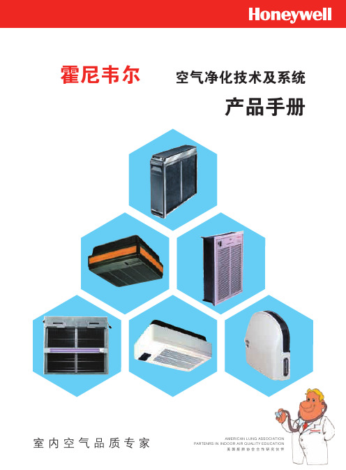
霍尼韦尔空气净化电子样本
600×442×162mm
16.4kg(运输) 14kg(安装)
UL 认证
F58G 空调箱适配型电子空气净化机
特性:
• 每个单元最大处理容量2000cfm(3400m3/h) • 多个单元可组成排列的空气净化机 • 指示灯可显示正常运行及故障情形 • 可与楼宇管理系统连接使用 • 电镀的机箱可防止生锈 • 测试按钮检查系统运行 • 预过滤网保护电子单元不受大颗粒污染 • 可有效去除悬浮在空气中直径为0.3μ的微粒 • 可与紫外线灯配套应用 • 发生误操作或电子单元需要清洗时,电子继电器将停止工作 • 电子单元在相当范围内负载时,固态电源供应组合可自我调
性能参数表
型号 电子单元数量 处理风量 安装方式 面板 / 格栅形式
组成
电源 运行环境 尺寸 重量 认证
F52G1012
F52G2002
1
1000cfm (1700m3/h)
回风口型
百叶
固态电源供应组合, 电子单元,预过滤网,格栅
电子单元,预过滤网,格栅
220V/50Hz
无电源供应
40oF-125oF (4oC-52oC)
740×485×273mm
31.5kg(运输) 29.5kg(安装)
18.5kg(运输) 16kg(安装)
UL 认证
CE 认证
F57A/B 嵌入式电子空气净化机
特性:
• 三速电机驱动循环风机 F57A额定处理风量可达875cfm (1500m3/h) F57B额定处理风量可达460cfm (782m3/h)
做为整体过敏症治疗方案中的一部分,Honeywell电子空气净化机的应用可以减轻过敏症和其它呼吸问题给患 者带来的伤害。然而,并不是所有类型的空气净化机都能达到此处理效果。
AMD微雾分离器系列商品介绍说明书
SymbolAMDMicro Mist SeparatorSeries AMDCan separate and remove aerosol state oil mist in compressed air and remove particles such as carbon or dust of more than 0.01 μm.Use this product as a pre-filter for compressed air for precision instruments or clean room requiring higher clean air.Specifications0.05 MPa 1.5 MPa FluidMax. operating pressure Min. operating pressure ∗Proof pressureAmbient and fluid temperature Nominal filtration rating Element lifeCompressed air1.0 MPa 5 to 60°C0.01 μm (Filtration efficiency: 99.9%)Oil mist density at outlet Max. 0.1 mg/m 3 (ANR)∗(Before saturated with oil, less than 0.01 mg/m 3 (ANR) ≈0.008 ppm)2 years (1 year for flange type)or when pressure drop reached 0.1 MPa∗ With auto drain: 0.1 MPa (N.O. type) or 0.15 MPa (N.C. type)∗ Oil mist density at 30 mg/m 3 (ANR) blown out by compressor.Modular connection is possible with AMD150C to 550C.(For details, refer to page 61.)AMD150C to 550C AMD650/850Made to Order(For details, refer to page 67.)CautionBe sure to read this before handling.Refer to back pages 1 and 2 for Safety Instructions, “Precautions for Handling Pneumatic Devices” (M-03-E3A) for Common Precautions, and back pages 3 through to 7 for Specific Product Precautions.o u r t e s y o f C M A /F l o d y n e /H y d r a d y n e ▪ M o t i o n C o n t r o l ▪ H y d r a u l i c ▪ P n e u m a t i c ▪ E l e c t r i c a l ▪ M e c h a n i c a l ▪ (800) 426-5480 ▪ w w w .c m a f h .c o mHow to Order OptionsSeries AMD ourtesyofCMA/Flodyne/Hydradyne▪MotionControl▪Hydraulic▪Pneumatic▪Electrical▪Mechanical▪(8)426-548▪www.cmafh.comHow to OrderA M D 10A M D 90, 91A M D 850A M D 80 , 81A M D 650A M D 550C A M D 450C A M D 350CA M D 250CA M D 150CAMD 65010Free standing type AMD800/810 to 10 0Piping support type 2000AMD 82001AMD 8Maximum Air FlowMax. flow lineModel SelectionSelect a model in accordance with the following procedure taking the inlet pressure and the max. air flow rate into consideration.(Example) Inlet pressure: 0.6 MPaMax. air flow rate: 5 m 3/min (ANR)1.Obtain the intersecting point A of inlet pressure and max. air flow rate in the graph.2. The AMD650 is obtained when the max. flow line is above the in-tersecting point A in the graph.Body size8910Body size89DescriptionWith differential pressure gauge (GD40-2-01)With differential pressure switch(With indicator, 125 VAC, 30 VDC)With IN-OUT flangeWith differential pressure gauge(GD40-2-01) and IN-OUT flangeN.C., N.O. auto drain, drain piping type White vaseline specificationsPage for details —P.68P.68P.69P.69X6X37X15X17P.70P.70X26X12Symbol Made to Order(“How to Order” and the applicable models are different from those shown on this page. Be sure to refer to “Made to Order”.)—Nil60150(6B)JIS 10K FF flange2050(2B)JIS 10K FF flange 3080(3B)JIS 10K FF flange 40100(4B)JIS 10K FF flange Port sizeSizeApplicable body sizeAMD800, 810AMD9 0AMD10 0Symbol00With manual drain cock 10With auto drainTypeDescription SymbolThread typeNilRc F G NNPTType Symbol Type01With manual drain cock 11With auto drainDescriptionSymbolAuto drain specifications/Option Auto drain specifications Option Option Auto drain specificationsD J R DJ T R Applicable modelAMD650AMD850N.O. auto drainDrain guide IN-OUT reversal directionTWith element service indicator14Auto Drain Specifications/Option Combinations: Available: Not availablePort size10142011122SizeApplicable body size650850Symbol Body size650850∗1Bracket is included,(but not assembled).AccessoryDescription —Bracket ∗1Symbol BNil Auto drain ∗2DescriptionDrain cock (Without auto drain) ∗3N.O. auto drainSymbol DNil∗2 Refer to “Auto Drain Specifications/Option Combinations”.∗3Body size 850 is equipped with a ball valve (Rc3/8 femalethreaded). Mount a piping adapter IDF-AP609 (page 62) to the ball valve if NPT3/8 female threaded is required.With element service indicatorOption ∗2Drain guide female threaded ∗4IN-OUT reversal direction 14Description—TJ R Symbol Nil∗4Drain piping and piping for a stopvalve such as ball valve are required.AMD650/850AMD801/811/9 1Port size2050(2B)JIS 10K FF flange 3080(3B)JIS 10K FF flange 40100(4B)JIS 10K FF flangeSizeApplicable body sizeAMD8 1AMD9 1SymbolNote)Make sure to select a model that has the max. flow line abovethe obtained intersecting point. With a model that has the max. flow line below the obtained intersecting point, the flow rate will be exceeded, thus leading to a problem such as being unable to satisfy the specifications.M a x . a i r f l o w r a t e (m 3/m i n (A N R ))Note) Refer to “How to Order BowlAssembly” on page 63.Micro Mist Separator SeriesAMDo u r t e s y o f C M A /F l o d y n e /H y d r a d y n e ▪ M o t i o n C o n t r o l ▪ H y d r a u l i c ▪ P n e u m a t i c ▪ E l e c t r i c a l ▪ M e c h a n i c a l ▪ (800) 426-5480 ▪ w w w .c m a f h .c o mAMD150C AMD250C AMD350C AMD450C AMD850AMD80 /81AMD650AMD10 0AMD550C AMD9 0/9 1Note) Compressed air over max. flow line in the table below may not meet the specifications of the product.It may cause damage to the element.Flow Characteristics /Select the model taking the max. flow capacity into consideration. ( Element oil saturation Initial condition)P r e s s u r e d r o p (M P a )Air flow rate (l /min (ANR))P r e s s u r e d r o p (M P a )Air flow rate (l /min (ANR))P r e s s u r e d r o p (M P a )Air flow rate (m 3/min (ANR))P r e s s u r e d r o p (M P a )Air flow rate (l /min (ANR))P r e s s u r e d r o p (M P a )Air flow rate (l /min (ANR))P r e s s u r e d r o p (M P a )Air flow rate (l /min (ANR))P r e s s u r e d r o p (M P a )Air flow rate (m 3/min (ANR))P r e s s u r e d r o p (M P a )P r e s s u r e d r o p (M P a )P r e s s u r e d r o p (M P a )Air flow rate (m 3/min (ANR))Max. flow lineMax. flow lineMax. flow lineMax. flow lineMax. flow lineMax. flow lineMax. flow lineMax. flow lineMax. flow lineMax. flow lineSeries AMDo u r t e s y o f C M A /F l o d y n e /H y d r a d y n e ▪ M o t i o n C o n t r o l ▪ H y d r a u l i c ▪ P n e u m a t i c ▪ E l e c t r i c a l ▪ M e c h a n i c a l ▪ (800) 426-5480 ▪ w w w .c m a f h .c o mIN OUTElementConstructionAMD150C to 550C, AMD650AMD850AMD80 /81 /9 0/9 1/10 0OUTIN ∗ Element assembly: With gasket (1 pc.) and O-ring (1 pc.)∗ Refer to back page 6 for replacement of auto drain.∗ Element assemblies for Made to Order (X6, X12, X15, X17, X20, X26, X37) are same as those for standard (see the above table).∗ The AMD850 is aluminum casted.Note) Sight glass is indicated in the figure for easy understanding ofcomponent parts. However, it differs from the actualconstruction. Refer to dimensions on pages 31 through to 34 for details.Micro Mist Separator SeriesAMDo u r t e s y o f C M A /F l o d y n e /H y d r a d y n e ▪ M o t i o n C o n t r o l ▪ H y d r a u l i c ▪ P n e u m a t i c ▪ E l e c t r i c a l ▪ M e c h a n i c a l ▪ (800) 426-5480 ▪ w w w .c m a f h .c o mAMD150C to 550CC: With auto drain (N.C.)D: With auto drain (N.O.)OptionJ: Drain guide 1/4 female threadedCombination of D: With auto drain (N.O.) S, U: With differential pressure switch (with indicator)T: With element service indicatorDimensionsSeries AMDo u r t e s y o f C M A /F l o d y n e /H y d r a d y n e ▪ M o t i o n C o n t r o l ▪ H y d r a u l i c ▪ P n e u m a t i c ▪ E l e c t r i c a l ▪ M e c h a n i c a l ▪ (800) 426-5480 ▪ w w w .c m a f h .c o m18076853111601502015114.512136160402533341032205537M a i n t e n a n c e s p a c eAMD150C to 550C, AMD650T: With element service indicatorDrainINOUTINOUT(Accessory)Bracket Auto drainD: With auto drain (N.O.)OptionJ: Drain guide 1/4 female threaded201/4 female threaded34Drain cock: Blackø10 one-touch fittingDimensionsMicro Mist Separator SeriesAMDo u r t e s y o f C M A /F l o d y n e /H y d r a d y n e ▪ M o t i o n C o n t r o l ▪ H y d r a u l i c ▪ P n e u m a t i c ▪ E l e c t r i c a l ▪ M e c h a n i c a l ▪ (800) 426-5480 ▪ w w w .c m a f h .c o m22011061818422022018024131530348464101204246158Rc 3/8 female threadedM a i n t e n a n c e s p a c e DrainBracket (Accessory)2 x port sizeAMD850T: With element service indicatorAuto drainD: With auto drain (N.O.)for AMD850Option233/8 female threadedDimensionsSeries AMDOUTININ OUTo u r t e s y o f C M A /F l o d y n e /H y d r a d y n e ▪ M o t i o n C o n t r o l ▪ H y d r a u l i c ▪ P n e u m a t i c ▪ E l e c t r i c a l ▪ M e c h a n i c a l ▪ (800) 426-5480 ▪ w w w .c m a f h .c o mLabelLabelDrain≈≈ORIENTATIONORIENTATIONAMD801/811/9 1AMD800/810/9 0/10 0Model500A720M16 x l 400Anchor bolt M20 x l 500AMD800/810AMD9 0Connection (Flange)50(2B), 80(3B)JIS 10K FF flange50(2B), 80(3B), 100(4B)JIS 10K FF flange 100(4B), 150(6B)JIS 10K FF flange870M20 x l 500AMD10 0300øB 560745200(8B)øC 400550300D3003001300E 132013801430F 148016101520G 1585174020H2424ModelConnection (Flange)50(2B)JIS 10K FF flange50(2B), 80(3B), 100(4B)JIS 10K FF flange400A620AMD801/811AMD9 1280øB 445150(6B)øC 300(12B)760D795150E300270F5201033G13183H3887J9723 x øH holesDimensionsMicro Mist Separator SeriesAMDIN OUTIN OUTOUT INOUTINOUTo u r t e s y o f C M A /F l o d y n e /H y d r a d y n e ▪ M o t i o n C o n t r o l ▪ H y d r a u l i c ▪ P n e u m a t i c ▪ E l e c t r i c a l ▪ M e c h a n i c a l ▪ (800) 426-5480 ▪ w w w .c m a f h .c o m。
联想昭阳k4450a-bois中文对照说明-推荐下载

Nerwork------网络
Wake on lan******[ac only]/disabled/ac and battery 网络唤醒******只交流/关闭/交流和电池 Ethernet lan option rom******[enabled]/disabled 可以从集成的网络设备启动******允许/关闭 Wireless lan radio******[on]/off 无线局域网
对全部高中资料试卷电气设备,在安装过程中以及安装结束后进行高中资料试卷调整试验;通电检查所有设备高中资料电试力卷保相护互装作置用调与试相技互术关,系电通,力1根保过据护管生高线0产中不工资仅艺料可高试以中卷解资配决料置吊试技顶卷术层要是配求指置,机不对组规电在范气进高设行中备继资进电料行保试空护卷载高问与中题带资22负料,荷试而下卷且高总可中体保资配障料置23试时23卷,各调需类控要管试在路验最习;大题对限到设度位备内。进来在行确管调保路整机敷使组设其高过在中程正资1常料中工试,况卷要下安加与全强过,看2度并55工且22作尽2下可护1都能关可地于以缩管正小路常故高工障中作高资;中料对资试于料卷继试连电卷接保破管护坏口进范处行围理整,高核或中对者资定对料值某试,些卷审异弯核常扁与高度校中固对资定图料盒纸试位,卷置编工.写况保复进护杂行层设自防备动腐与处跨装理接置,地高尤线中其弯资要曲料避半试免径卷错标调误高试高等方中,案资要,料求编5试技写、卷术重电保交要气护底设设装。备备4置管高调、动线中试电作敷资高气,设料中课并3技试资件且、术卷料拒管中试试调绝路包验卷试动敷含方技作设线案术,技槽以来术、及避管系免架统不等启必多动要项方高方案中式;资,对料为整试解套卷决启突高动然中过停语程机文中。电高因气中此课资,件料电中试力管卷高壁电中薄气资、设料接备试口进卷不行保严调护等试装问工置题作调,并试合且技理进术利行,用过要管关求线运电敷行力设高保技中护术资装。料置线试做缆卷到敷技准设术确原指灵则导活:。。在对对分于于线调差盒试动处过保,程护当中装不高置同中高电资中压料资回试料路卷试交技卷叉术调时问试,题技应,术采作是用为指金调发属试电隔人机板员一进,变行需压隔要器开在组处事在理前发;掌生同握内一图部线纸故槽资障内料时,、,强设需电备要回制进路造行须厂外同家部时出电切具源断高高习中中题资资电料料源试试,卷卷线试切缆验除敷报从设告而完与采毕相用,关高要技中进术资行资料检料试查,卷和并主检且要测了保处解护理现装。场置设。备高中资料试卷布置情况与有关高中资料试卷电气系统接线等情况,然后根据规范与规程规定,制定设备调试高中资料试卷方案。昭阳 4450a bios 中文对照
EM4150A5WW11中文资料(EM Microelectronic)中文数据手册「EasyDatasheet - 矽搜」

EM微电子
- MARIN SA
EM4150 EM4350
1千比特读/写
非接触式识别装置
描述 该EM4150 / EM4350(以前称为P4150 / P4350) 是CMOS集成电路打算用于电子 读/写射频转发器.该芯片包含1千位 EEPROM,可以由用户来配置,允许写入禁止区,读出防 护护区,和一个连续地读区域输出功率上.存储器可以 通过使用所有写入和读防护护操作32位密码被固定. 密码可以被更新,但从来不看.固定代码序列号和设备标 识是激光编程尽一切芯片独一无二.
Control Word 0 - 7 First Word Read
8 - 15 Last Word Read 16 Password Check On/Off 17 Read After Write On/Off
18 - 31 User available
On means bit set to logic '1' Off means bit set to logic '0'
Device Identification Word & Serial Number Word Laser Programmed - Read Only
图. 6
4
芯片中文手册,看全文,戳
标准读模式
经过上电复位和一个完成时
命令,芯片将执行标准读
模式,将在其中通过连续发送数据,字
从第一之间限定存储器部分字
□ 场频位周期= 64或32学时 □ 170 pF±2%片上谐振电容 □ -40至+ 85°C温度范围 □ 100至150 kHz场频范围 □ 片上整流器和电压限制器 □ 由于无需外部电源缓冲电容
富士内镜EPX-4450主机配小肠镜技术参数

23
患者数据输入
可以输入44位病人的基本资料和20位医生的资料。
*24
*兼容性
川兼容胃镜、超声内镜、经鼻内镜、肠镜、十一指肠镜、支气管镜、双气囊小肠镜、气囊式大肠镜等。
(二)内窥镜处理器光源:XL-4450
*1
光源
主灯:300W氤灯;备用灯:12V75W卤素灯。
2
光量调节
2
电压
230V,1.7A;50Hz
3
超级CCD设计
高画质效果,超强的图像分辨率和色彩还原性,为消化道早期癌症的筛查及微小病变的判别提供了更有效的诊断工具。
4
视频系统
具有NTSC以及PAL;
5
颜色调节
可进行红、绿、蓝、R-Hue颜色、灰度、色饱和度调节;
6
自动白平衡
具有自动白平衡功能
7
自动测光模式
平均测光、峰值测光、自动测光三种模式
3
电源线
医用3芯插头
4
熔断器
250V-T5A
5
气囊设定压力
5.6Kpa
6
设定压力允许公差
士2Kpa
7
8.2kpa
取人JL阡压力
8
气泵取大流里
085L/min
高清内镜专用监视器
高清内镜专用监视器:
1
原装进口
2
医用液晶监视器
3
屏幕尺寸
>19寸
4
监视器分辨率
>1280*1024
仪器车
单臂仪器车:
(1台)
1
专用仪器车
小巧、结构紧凑,可以容纳电子内镜系统常用设备
2
内镜支架
可升降支架,同时悬挂两条镜子
EM4450A5WT7E中文资料(EM Microelectronic)中文数据手册「EasyDatasheet - 矽搜」
coil = 1V pp , T op = 25℃,除非另有说明
参数
符号
条件
Min Typ Max Unit
电源电压
最小EEPROM写
电压
VDD VDDee
2.3
3.2
V
2
V
电源检查EEPROM写 电源电流/读
I PWcheck Ird
VDD = 2.8V
阅读模式
32
µA
3
µA
就给电流/写
调制器接通电压降
32 160 1600 32 32 1056 2624
射频周期表示由收发器单元发射载波频率周期.例如,如果125千赫时: 读位周期(Opt64)将是:1/125'000 * 64 = 512微秒,和时间来阅读1字:1/125'000 * 3200 = 25.6毫秒. 读位周期(Opt32)将是:1/125'000 * 32 = 256微秒,和时间来阅读1字:1/125'000 * 1600 = 12.8毫秒.
±30毫安
-0.3 to 3.5 V VDD+0.3V VSS-0.3V
-55至+ 125°C
VESD
2000V
强调上述这些上市最大额定值可能会造成永久性损坏设备.曝光超出规定工作条件可能影响器件可靠性或造成 故障.
处理程序 该器件内置防静电高电压或电场;但是,防静电必须采取预防措施作为任何其它CMOS组件.除非另有规定,只能当所有端 电压防护持在电压范围内发生正确操作.未使用输入必须始终连接到一个定义逻辑电平.
V(COIL1 - VSS) & V (COIL2 - VSS) Icoil =5毫安
瑞星供应
联想ThinkPad E40参数

联想ThinkPad E40(0578A64)参数规格基本参数上市时间2010年10月产品类型商用产品定位沉稳商务本操作系统Windows 7 Home Basic(家庭普通版)主板芯片组Intel HM55处理器CPU系列英特尔酷睿i3CPU型号Intel 酷睿i3 370MCPU主频 2.4GHz三级缓存3MB核心类型Clarksfield核心/线程双核心/四线程数存储设备内存容量2GB内存类型DDR3 1066MHz最大内存容8GB量硬盘容量320GB硬盘描述5400转,SATA光驱类型DVD刻录机设计类型光驱内置显示屏屏幕尺寸14英寸屏幕比例16:9屏幕分辨率1366x768背光技术LED背光显卡显卡类型中低端独立显卡显卡芯片ATI Mobility Radeon HD 545v 显存容量512MB显存位宽64bit流处理器数80量DirectX 10.1多媒体设备摄像头集成摄像头音频系统Intel High Definition Audio扬声器立体声扬声器麦克风内置麦克风网络通信无线网卡支持802.11b/g/n无线协议有线网卡1000Mbps以太网卡I/O接口数据接口3×USB2.0,e-SATA接口视频接口VGA音频接口耳机输出接口,麦克风输入接口其它接口RJ45(网络接口),电源接口读卡器7合1读卡器(MMC,SD,MS,MS-Pro,xD,SDHC)扩展插槽ExpressCard输入设备指取设备触摸板,指点杆键盘描述支持多点触摸电源描述电池类型4芯锂电池续航时间具体时间视使用环境而定电源适配器100V-240V 自适应交流电源适配器外观笔记本重量 2.25Kg外形尺寸344×233×31.8-37mm外壳材质复合材质外壳描述午夜黑(雅光面)其他附带软件随机软件笔记本附件包装清单笔记本主机x1 电池x1电源适配器x1 说明书x1保修信息保修政策全国联保,享受三包服务质保时间1年质保备注1年部件和人工,客户送修客服电话800-990-8888电话备注周一至周五:8:30-17:30(节假日休息)详细内容产品免费保修期内,您在中华人民共和国境内(不包括港、澳、台地区)购买并使用的联想公司在中国大陆地区正式发布的产品出现本服务承诺责任范围内的硬件故障,请您首先拨打联想Think报修热线进行报修。
MOXA NE-4100系列网络启用器产品介绍说明书
P/N: 1802041000302*1802041000302*NE-4100 Series Quick Installation GuideVersion 5.1, December 2019Technical Support Contact Information /support Moxa Americas:Toll-free: 1-888-669-2872Tel: 1-714-528-6777Fax: 1-714-528-6778 Moxa China (Shanghai office): Toll-free: 800-820-5036 Tel: +86-21-5258-9955 Fax: +86-21-5258-5505 Moxa Europe:Tel: +49-89-3 70 03 99-0Fax: +49-89-3 70 03 99-99 Moxa Asia-Pacific: Tel: +886-2-8919-1230 Fax: +886-2-8919-1231 Moxa India:Tel: +91-80-4172-9088Fax: +91-80-4132-10452019 Moxa Inc. All rights reserved.OverviewThe MOXA NE-4100 Series of Network Enablers are serial-to-Ethernet embedded modules that come in 3 types: drop-in type (NE-4100T), RJ45 type (NE-4110S/A), and pin-header type (NE-4120S/A). MOXA provides a Starter Kit for each NE-4100 series module. Each Starter Kit contains an evaluation board that can be used to evaluate the modules and to develop applications. The following table lists the model names of all NE-4100 Series modules, along with the model names of the corresponding Starter Kits.Starter Kit Model NamesNE-4100 Series Model Names Standard ProgrammableNE-4100-ST NE-4100T NE-4100T-PNE-4110-ST NE-4110S NE-4110S-P NE-4110A NE-4110A-PNE-4120-ST NE-4120S NE-4120S-P NE-4120A NE-4120A-PPackage ChecklistEach NE-4100 series starter kit package contains the following items: • 1 NE-4100 series evaluation board• 1 universal power adaptor• 2 power cords• 1 null modem serial cable• 1 cross-over Ethernet cable• 1 quick installation guide (printed)• 1 warranty cardNotify your sales representative if any of the above items is missing or damaged.Hardware Installation ProcedureFollow these steps to prepare the module and evaluation board for testing and application development.STEP 1: Plug the NE-4100 module into the sockets on the top of the evaluation board.NE-4100-ST:After attaching the module to the evaluation board, the triangles on the module and evaluation board should line up.NE-4100-ST Starter KitNE-4110-ST:The module and evaluation board have two jumper arrays, each with a pin labeled 1. Be sure to connect the correct Pin 1 on the module to the correct Pin 1 on the evaluation board.NE-4110-ST Starter KitNE-4120-ST:The module and evaluation board have two jumper arrays, each with a pin labeled 1. Be sure to connect the correct Pin 1 on the module to the correct Pin 1 on the evaluation board.NE-4120-ST Starter KitNOTE For detailed information about the pin assignments, wiring, LED indicators, and board layouts, refer to Chapter 2 of the NE-4100 Series User’s Manual.STEP 2: Connect the 12 VDC power line with the evaluation board’s power jack.STEP 3: Use an RJ45 Ethernet cable to connect the NE evaluation board plus module to an Ethernet network. Note that for NE-4100T and NE-4120, the RJ45 Ethernet port is located on theevaluation board. For NE-4110, the RJ45 Ethernet port islocated on the module itself.STEP 4: Use the serial data cable to connect the evaluation board to a serial device.STEP 5: For NE-4110-ST and NE-4120-ST, use jumper JP2 on the evaluation board to select the proper serial interface. Seepages 3-6 and 3-7 of the NE-4100 Series User’s Manual fordetails.Software Utility Installation ProcedureNE-4100 ModuleSoftware Installation1.Start the “Network Enabler Administrator” setup program to beginthe installation. When the Welcome window opens, click on Next.2.When the Select Additional Tasks window opens, click on Next.3.Click on Install to install program files in the default directory.4.The Installing window reports the progress of the installation.5.Click on Finish to complete the installation.Module Configuration1.Start the “Network Enabler Administrator” program.2.Click on Configuration from the menu bar, and then selectBroadcast Search from the drop-down menu.3.After the search is finished, all NE-4100 modules that were foundwill be shown in the right panel of the Configuration window. Ifyou locate more than one module connected to this network, refer to the MAC address on the module(s) to determine which modules are the ones you wish to configure.4.Refer to pages 7-6 to 7-19 of the NE-4100 Series User’s Manualfor additional configuration instructions.NE-4100 Programmable ModuleSoftware Installation1.Start the “Network Enabler SDK” setup program to begin theinstallation. When the Welcome window opens, click on Next. 2.Select the target directory, and then click on Next when theSelect Destination Directory window opens.3.Click on Next when the Select Additional Tasks window opens.4.Click on Install. The Installing window will report the progress ofthe installation.5.Click on Finish to complete the installation.Module Configuration1.Start the “NE SDK Manager” program.2.Click on Search from the menu bar, and then select BroadcastSearch from the drop-down menu.3.After the search is finished, all NE-4100-P modules that werefound will be shown in the NE SDK Manager window. Refer to the “Network Enabler SDK 2 Programmer’s Guide” for additionalinformation about setting environment variables and developingapplications with NE-4100-P Series products.Reference MaterialThe following detailed user’s guides can be downloaded from Moxa’s product page under the NE-4100 Series’ product page.NE-4100 Standard Module•NE-4100 Series User’s ManualNE-4100-P Series•Network Enabler SDK 2 Programmer’s Guide•Network Enabler SDK 2 API Reference。
Bird 4421 RF Power Meter 44说明书

Bird 4421 RF Power Meter44SpecificationsNOTE: Due to the wide variety of available connectors, frequencyrange and maximum power may be reduced. Insertion loss isspecified with female N connectors. Choose connectors appropriate for the frequency and power of operation.Bird 4421 RF Power MeterFrequency Range Sensor dependent Power Range Sensor dependent VSWR Display 1.0 – 199.9 max Return Loss Display 0 to 40 dB maxDisplay Accuracy ± 1 on least significant digit AC Power 115/230 Vac @ 50/60 HzBatteries 8 C-size Nickel Cadmium rechargeable 1.2 volt cells, 15 W max (NEDA Type 10014)Battery Life Minimum 8 hours continuous usage Battery ChargerBuilt-in battery charger. Drained batteries require approximately 28 hours to recharge.DisplayLCD, 3 ½ digit display. Indicates mode,measurement units, battery condition, remote status, and signal increase/decrease. Self contained backlight.Optional Interfaces IEEE-488 GPIB RS-232Fuse RatingIEC (5 x 20 mm) Type T 115 Vac 230 Vac 0.25 A 0.125 AEmissions/Immunity EMC Directive 89/336/EEC Safety Low Voltage Directove 73/23/EEC Humidity 95% ± 5% max. (noncondensing)AltitudeUp to 10,000 feet (3,048 m)Temperature RangeOperating Storage 0 to 50 °C (32 to 122 °F)–20 to +50 °C (–4 to +122 °F)Dimensions 15.5”L x 12.25”W x 4.25”H (393 x 311 x 108 mm)Weight9.5 lbs. (4.3 kg) nominal1981Maintenance45Specifications Common to all SensorsImpedance 50 ohms nominalVSWR Range 1.00 to 2.00 (40.0 to 9.5 dB Return Loss)Sampling Rate Approximately 2 readings/secondCalibration Technique Calibration vs. frequency curve stored in nonvolatile memory in each sensor. Sensor output corrected at frequency of measurement within rated range.Operating Power Supplied by power meter via sensor cable ConnectorsCustomer specified (See “Available Connectors” on page 50)Emissions/Immunity EMC Directive 89/336/EEC Safety Low Voltage Directove 73/23/EEC Humidity 95% ± 5% max. (noncondensing)AltitudeUp to 10,000 feet (3,048 m)Temperature RangeOperating Storage 0 to 50 °C (32 to 122 °F)–20 to +50 °C (–4 to +122 °F)Dimensions 5.4”L x 2.5”W x 3.25”H (137 x 64 x 83 mm)Weight, Nominal1 lb. 13 oz. (0.8 kg)Bird 4421 RF Power Meter46Bird 4020 Series RF Power SensorsPower Range4021, 40224024, 4025300 mW – 1 kW3 W – 10 kWFrequency Range40214022402440251.8 – 32 MHz25 MHz – 1 GHz1.5 – 32 MHz100 kHz – 2.5 MHzAccuracy, Fwd± 3%Insertion VSWR (Insertion Loss)4021, 4024, 402540221.05 (0.05 dB) max1.05 (0.05 dB) max, 25 – 512 MHz1.10 (0.13 dB) max, 512 MHz – 1 GHz Directivity, Minimum4021, 40224024402530 dB30dB (2.5 – 25 MHz), 28 dB (1.5 – 32 MHz)30 dB (125 – 2500 kHz), 28 dB (100 – 125 kHz) Signal PurityFor rated accuracy no more than 1% AMHarmonics –50 dB or lessMaintenance47CAUTIONChanging the sensor’s connectors will invalidate calibration data,and may reduce the maximum power rating of the unit.Bird 4027A Series RF Power SensorsPower Range4027A12M 4027A25M 4027A35M 4027A60M 4027A100M 4027A150M All other models300 mW – 1 kW 3 W – 9 kW 3 W – 7.5 kW 3 W – 6 kW 3 W – 5 kW 3 W – 4 kW 3 W – 10 kWFrequency Range (Calibration Frequency)4027A250K 4027A400K 4027A800K 4027A2M 4027A4M 4027A10M 4027A12M 4027A25M 4027A35M 4027A60M 4027A100M 4027A150M 250 – 400 kHz (250 kHz)400 – 550 kHz (400 kHz)800 – 950 kHz (900 kHz)1.5 – 2.5 MHz (2.0 MHz)3 – 5 MHz (4.0 MHz)10 – 15 MHz (13.56 MHz)10 – 15 MHz (13.56 MHz)25 – 30 MHz (27.12 MHz)35 – 45 MHz (40.0 MHz)45 – 65 MHz (60.0 MHz)95 – 105 MHz 150 – 170 MHzAccuracy±2 % from maximum range to 30 % of full scale on the most sensitive range±1 % at calibration frequency and power level Repeatability ±1 % maximum unit to unit at calibration frequency and power level Insertion VSWR (Insertion Loss) 1.05 (0.05 dB) maxDirectivity, Minimum4027A12MAll other models 30 dB 28 dBSignal PurityFor rated accuracy no more than 1% AM Harmonics –50 dB or less Calibration Power Level1 kW unitsAll other models700 W 1700 WBird 4421 RF Power Meter48Bird 4027F Series RF Power SensorsPower Range100 W – 10 kWFrequency Range4027F2M4027F10M1.8 –2.2 MHz12 – 15 MHzPower Accuracy15 to 35 °C (59 to 95 °F)0 to 50 °C (32 to 122 °F)± 1%± 3%Harmonic Rejection, Minimum4027F2M4027F10Mfrequency > 3.8 MHz:30 dB3.6 – 3.8 MHz:26 dBfrequency > 25 MHz:30 dB Low Frequency Rejection, Minimum (4027F10M Only) frequency < 1 MHz30 dBAM Rejection< 5 kW, 10% AM5 – 10 kW, 10% AM< 0.2% error< 1% errorInsertion VSWR(Insertion Loss)1.05 (0.05 dB) max Directivity, Minimum28 dBCalibration Power Level1700 W nominal Calibration Frequencies4027F2M4027F10M1.80,2.00, 2.20 MHz12.0, 13.56, 15.0 MHzMaintenance49IEEE-488 Interface ModuleLogic Levels Meets all IEEE Standard 488-1978 specificationsModes of OperationSwitch and bus selectableTalk Only Allows the 4421 to send to the bus keyboard-initiated measurements onlyAddressableAllows the 4422 to be addressed as talker or listener under the command of an IEEE-488 bus controllerConnector Standard IEEE-488 bus typeHumidity 95% ± 5% maximum (non-condensing)AltitudeUp to 10,000 feet (3,048 m)Temperature RangeOperating Storage 32 to 122º F (0 to 50º C)–4 to +122º F (–20 to +50º C)Dimensions 6.5”L x 4.5” W (165.1 x 114.3 mm)Weight0.5 lbs (0.227 kg) nominalRS-232 Interface ModuleLogic Levels Meets all EIA Standard RS-232-C specifications Modes of OperationSwitch and bus selectableTalk Always Allows the 4421 to send to the bus keyboard-initiated measurements onlyAddressable Allows the 4421 to be commanded by an RS-232 interface controller Connector RS-232 Interface TypeHumidity 95% ± 5% maximum (non-condensing)AltitudeUp to 10,000 feet (3,048 m)Temperature RangeOperating Storage 32 to 122º F (0 to 50º C)–4 to +122º F (–20 to +50º C)Dimensions 6.5”L x 4.5” W (165.1 x 114.3 mm)Weight0.5 lbs (0.227 kg) nominal。
笔记本配置
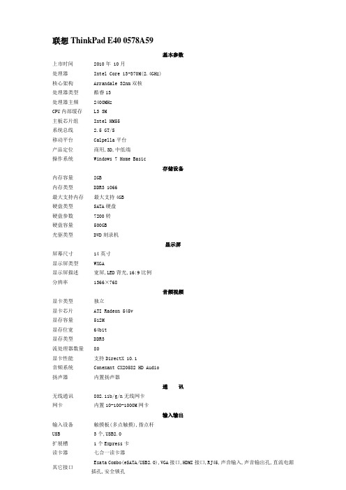
联想ThinkPad E40 0578A59基本参数上市时间 2010年 10月处理器 Intel Core i3-370M(2.4GHz)核心架构 Arrandale 32nm双核处理器类型酷睿i3处理器主频 2400MHzCPU内部缓存 L3 3M主板芯片组 Intel HM55系统总线 2.5 GT/S移动平台 Calpella平台产品定位商用,3D,中低端操作系统 Windows 7 Home Basic存储设备内存容量 2GB内存类型 DDR3 1066最大支持内存最大支持4GB硬盘类型 SATA硬盘硬盘参数 7200转硬盘容量 500GB光驱类型 DVD刻录机显示屏屏幕尺寸 14英寸显示屏类型 WXGA显示屏描述宽屏,LED背光,16:9比例分辨率1366×768音频视频显卡类型独立显卡芯片 ATI Radeon 545v显存容量 512M显存位宽 64bit显存类型 DDR3流处理器数量 80显卡性能支持DirectX 10.1音频系统 Conexant CX20582 HD Audio扬声器内置扬声器通讯无线通讯 802.11b/g/n无线网卡网卡内置10-100-1000M网卡输入输出输入设备触摸板(多点触摸),指点杆USB 3个,USB2.0扩展槽 1个Express卡读卡器七合一读卡器其它接口 Esata Combo(eSATA/USB2.0),VGA接口,HDMI接口,RJ45,声音输入,声音输出孔,直流电源插孔,安全锁孔特色设备内置摄像头内置摄像头指纹识别器无指纹识别器结构特征重量约2.25Kg规格344×233×31.8-37.0mm电能规格电池类型 4芯锂电池工作时间约2.5小时其它可选配件锂电池,电源适配器,软件光盘,说明书保修 1年部件和人工,客户送修。
联想昭阳k4450a-bois中文对照说明
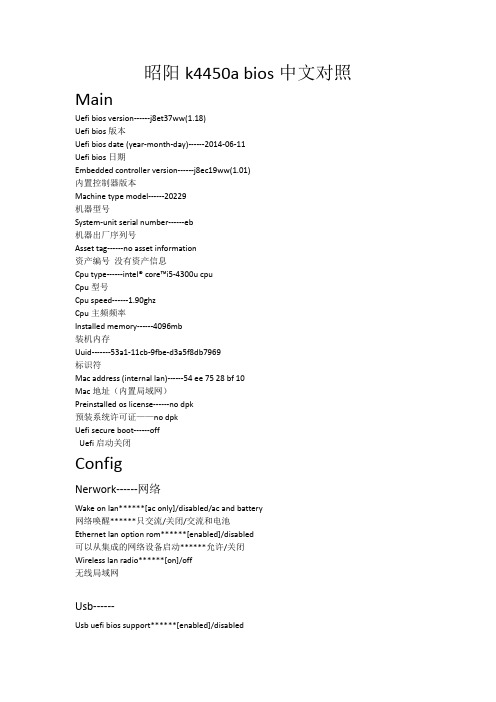
昭阳k4450a bios中文对照MainUefi bios version------j8et37ww(1.18)Uefi bios版本Uefi bios date (year-month-day)------2014-06-11Uefi bios日期Embedded controller version------j8ec19ww(1.01)内置控制器版本Machine type model------20229机器型号System-unit serial number------eb机器出厂序列号Asset tag------no asset information资产编号没有资产信息Cpu type------intel® core™i5-4300u cpuCpu型号Cpu speed------1.90ghzCpu主频频率Installed memory------4096mb装机内存Uuid-------53a1-11cb-9fbe-d3a5f8db7969标识符Mac address (internal lan)------54 ee 75 28 bf 10Mac地址(内置局域网)Preinstalled os license------no dpk预装系统许可证——no dpkUefi secure boot------offUefi启动关闭ConfigNerwork------网络Wake on lan******[ac only]/disabled/ac and battery网络唤醒******只交流/关闭/交流和电池Ethernet lan option rom******[enabled]/disabled可以从集成的网络设备启动******允许/关闭Wireless lan radio******[on]/off无线局域网Usb------Usb uefi bios support******[enabled]/disabledUsb启动Always on usb******[ enabled]/disabled永远开启usb-charge in battery mode******[disabled]/ enabled电池充电模式Usb 3.0 mode******[smart auto]/ disabled/ enabled/autoUsb 3.0模式******聪明的自动/关闭/开启/自动Keyboard/mouse------键盘鼠标Fn and ctrl key swap******[ disabled]/ enabledFn键与ctrl键切换*****关闭/开启Fn key lock******[ disabled]/ enabledFn键按下即锁定(关设定为fn按下有效,开设定为fn一直按下)Display------显示Boot display device******[Lenovo lcd]/analog (vga)/hdmi显示设备******联想lcd显示器/vga显示器/hdmi显示器Graphics device******[switchable graphics]/integrated graphics图形设备******可切换显卡/集显Os detection for switchable graphics******[ enabled]/disabled操作系统检测切换显卡Power------Intel ® speedstep technology******[ enabled]/disabledIntel ® speedstep技术(通电和电池状态切换技术)Cpu power management******[ enabled]/ disabledCpu电源管理Beep and alarm------警报Keyboard beep******[ enabled]/ disabled键盘警报Serial ata (sata)------Sata controller mode option******[ahci]/compatibilitySata控制模式选项******sata模式/兼容模式Cpu------Core multi-processing******[ enabled]/ disabled多核处理器Intel ® hyper-threading technology******[ enabled]/ disabled英特尔®超线程技术SecurityPassword------Supervisor password******[enter]-password status******disabledLock uefi bios settings******[disabled]/enabledPassword at unattended boot******[enabled] /disabledPassword at restart******[disabled]/ enabledSet minimum length******[disabled]/4 characters/5 characters/6 characters/7 characters/8 characters/9 characters/10 characters/11 characters/12 charactersPower-on password******[enter]-password status******disabledHard disk1 password******[enter]“setup confirmation******select ‘user’ only or ‘user + master ’******[user]/[user + master]”-password status******disabledHard disk2 password******[enter]“setup confirmation******select ‘user’ only or ‘user + master’******[user]/[user + master]”-password status******disabledUefi bios update option------ Uefi bios更新选项Flash bios updating by end-users******[enabled] /disabled由最终用户Flash bios更新Secure rollback prevention******[disabled]/enabled预防安全的回滚Memory protection------内存保护Execution prevention******[enabled] /disabled数据执行保护Virtualization------虚拟Intel ® virtualization technolog******[disabled]/enabled英特尔®虚拟化技术Intel® vt-d feature******[disabled]/enabled英特尔®vt-d特性i/o prot access------i / o访问选项Ethernet lan******[enabled] /disabled以太网Wireless lan******[enabled] /disabled无线网Bluetooth******[enabled] /disabled蓝牙Usb port******[enabled] /disabledUsb接口Memory card slot******[enabled] /disabled记忆卡槽Integrated camera******[enabled] /disabledMicrophone******[enabled] /disabled麦克风Fingerprint reader******[enabled] /disabled指纹识别anti-theft------防盗技术intel ® at module activation英特尔®模块激活-current setting******[enabled] /disabled/permanently disabled 当前设置-current state******not activated当前状态******没有激活Computrace-----追踪程序Computrace module activation追踪程序激活-current setting******[enabled] /disabled/permanently disabled 当前设置-current state******not activated当前状态******没有激活secure boot------安全启动secure boot******[disabled]/enabled安全启动platform mode******user mode平台模式******用户状态secure boot mode******standard mode安全启动模式******标准模式reset to setup mode******[enter]重置设置模式“setup confirmation****** reset to setup mode ?******[yes]/[no]”安装确认******重置设置模式?******restore factory keys******[enter]恢复出厂设置“setup confirmation****** restore factory keys ?******[yes]/[no]”安装确认******恢复出厂设置?******Startup启动Boot------Boot priority order启动优先顺序b cd3.ata hdd0 hgst htsa7e6304.ata hdd1 liteonit lss-16l6gb hdd6.pci lan realtek pxe b02 d00Excluded from boot priority order排除在引导优先顺序Network book******[ata hdd1:liteon]/usb cd/usb fdd/ata hdd0 hgst htsa7e630/ata hdd1 liteonit lss-16l6g/usb hdd/pci lan realtek pxe b02 d00网络启动Uefi/legacy boot******[both]/uefi only/legacy onlyUefi/传统BIOS启动******二者都使用-uefi/legacy boot priority******[legacy first]/uefi firstefi/传统BIOS优先顺序******-csm support******[yes]兼容性支持模块Boot mode******[quick]/diagnostics引导模式******【快速】/诊断Option key display******[enabled]/disabled选择键显示Boot device list f12 option******[enabled] /disabledF12键启用设备清单Boot order lock******[disabled]/ enabled启动顺序锁Restart重启Exit saving changes退出且保存更改“setup confirmation****** save configuration changes and exit now ?******[yes]/[no]”Exit discarding changes退出且不保存更改“setup warning****** configuration has not been saved ! save before exiting ?******[yes]/[no]”Load setup defaults读取默认值“setup confirmation****** Load defaults configuration now ? os optimized defaults disabled******[yes]/[no]”-os optimized******[disabled]/enabled系统优化Discard changes放弃更改“setup confirmation****** Load previous configuration now ? ******[yes]/[no]”Save changes保存更改“setup confirmation****** save configuration changes now ? ******[yes]/[no]”。
w79e2051_4051(中文)

8-位微控制器Publication Release Date: March 25, 2008目录-1 概述.............................................................................................................................................42 特性.............................................................................................................................................43 产品型号信息...............................................................................................................................5 3.1无铅(RoHS) 产品型号信息表列 (5)4 管脚配置......................................................................................................................................5 5 管脚描述......................................................................................................................................6 6功能描述......................................................................................................................................7 6.1 I/O 端口...........................................................................................................................7 6.2 串行 I/O...........................................................................................................................7 6.3 定时器.............................................................................................................................7 6.4 中断.................................................................................................................................7 6.5 数据指针..........................................................................................................................7 6.6CPU 架构........................................................................................................................7 6.6.1 ALU...................................................................................................................................7 6.6.2 累加器(ACC).....................................................................................................................8 6.6.3 B 寄存器............................................................................................................................8 6.6.4 程序状态字寄存器(PSW)...................................................................................................8 6.6.5 片内便签RAM....................................................................................................................8 6.6.6 堆栈指针............................................................................................................................8 7 内存组织......................................................................................................................................9 7.1 程序内存..........................................................................................................................9 7.2 数据存储器......................................................................................................................9 7.3 寄存器的映射..................................................................................................................9 7.4 工作寄存器....................................................................................................................11 7.5 位寻址区........................................................................................................................11 7.6堆栈 (11)8 特殊功能寄存器.........................................................................................................................13 9 指令...........................................................................................................................................34 9.1 指令时序........................................................................................................................42 10电源管理 (45)10.1 空闲模式........................................................................................................................45 10.2掉电模式 (45)11 复位条件 (47)11.1复位源 (47)11.1.1外部复位 (47)11.1.2上电复位 (POR) (47)11.1.3欠压复位(BOR) (47)11.1.4看门狗定时器复位 (47)11.2复位状态 (47)12INTERRUPTS (50)12.1中断源 (50)12.2中断优先级 (51)12.3中断响应时间 (52)13可编程定时器/计数器 (54)13.1定时器/计数器0&1 (54)13.2时基选择 (54)13.2.1模式0 (54)13.2.2模式1 (55)13.2.3模式2 (55)13.2.4模式3 (56)14数据存储器 (56)15看门狗定时器 (58)15.1看门狗控制 (59)15.2看门狗时钟控制 (59)16串行 (UART) (60)16.1模式 0 (60)16.2模式1 (61)16.3模式 2 (62)16.4模式 3 (63)16.5帧错误检测 (64)16.6多机通信 (64)17脉宽调制(PWM) (66)18模拟比较器 (68)18.1模拟比较器中断 (68)19时控访问保护 (70)20I/O端口配置 (72)20.1准双向端口模式配置 (72)20.2开漏端口模式配置 (73)21振荡器 (74)21.1片内RC振荡器选项 (74)21.2外部时钟输入选项 (74)22电源监视功能 (75)22.1欠压检测 (75)22.2ICP(在电路编程) FLASH 编程 (76)23配置位 (77)23.1CONFIG0 (77)23.2CONFIG1 (78)24电气特性 (79)24.1极限参数 (79)24.2DC 电气特性 (80)24.3模拟比较器电气特性 (82)24.4AC 电气特性 (83)24.5外部时钟特性 (83)24.6RC OSC 和 AC 规格 (83)25典型应用电路 (85)26封装尺寸 (86)26.120-pin SOP (86)26.220-pin DIP (87)27版本历史 (88)华邦电子(上海)集成电路有限公司(8位单片机)uC微控制器产品部上海市长宁区延安西路2299号27楼(邮编200336)电话:************传真:************Publication Release Date: March 25, 20081 概述W79E4051/2051系列是一个快速51微控制器,它有可以在系统编程的(ICP)应用程序Flash EPROM,可以使用烧写器在系统中编程。
上门维修记录单

楼道分支检查结构:
754MHz 256QAM A 处理意见:
处理结果:
备
注:
பைடு நூலகம்
制表人:王宏博
维修人员:
用户签字:
维护部上门维修记录单
维护单位: 机顶盒出现何种故障: 接头检查结果: 电源线检查结果: 入户链路检查结果: 入户线检测结果: 入户线检查结果: 用户电视检测结果: 楼道分支检查结构: 主线路检查结果: 用户家QAM检测结果: 频点 427MHz 746MHz 754MHz 频点 427MHz 746MHz 解调方式 64 QAM A 64 QAM A 256QAM A 解调方式 64 QAM A 64 QAM A MER 解码后BER MER 解码后BER 口 接头有问题 口 有接地线 口 全部为歌华器件 口 无其他干扰 口 无暗线问题 口 有电视馈电现象 口 用户出口指标正常 口 各个器件正常 频点 818MHz 826MHz 12CH 频点 818MHz 826MHz 12CH 解调方式 64 QAM A 64 QAM A 42CH 口 接头正常 口 无接地线 口 用户有私加器件 口 有其他干扰或与其他线路紧邻 口 有暗线问题 口 没有电视馈电现象 口 用户出口指标不正常 口 主线路信号出现问题 测试使用仪表: 解调方式 64 QAM A 64 QAM A 42CH MER 解码后BER MER 解码后BER 维修时间: 用户地址:
em4 em4 Ethernet 说明书

Ethernet›P rogram or debug your e m4 Ethernet fromanywhere on the Ethernet local network›C ooperate with up to 16 e m4 Ethernet or otherequipment with the Ethernet Modbus TCP/IPstandard protocol Client and Server›B y the Receive periodically datalogs by email orFTP in .CSV (Excel) file›G et an alert by email fully controlled by theapplication programProducts certification CE, cULus ListedConformity with the low voltage directive(in accordance with BT 2006/95/EC)IEC/EN 61131-2 (Open equipment)Conformity with the EMC directive (in accordance with 2004/108/EC)IEC/EN 61000-6-1 (Residential, commercial and light-industrial environments) IEC/EN 61000-6-2 (Industrial)IEC/EN 61000-6-3 (Residential, commercial and light-industrial environments) IEC/EN 61000-6-4 (Industrial)Power supply earthing NoneOvervoltage category 3 in accordance with IEC/EN 60664-1e m4 Ethernet - Glossy blackPollutionDegree: 2 in accordance with IEC/EN 61131-2Maximum utilization altitude Operation: 2000 m Transport: 3000 mMechanical resistanceImmunity to vibrations IEC/EN 60068-2-6, Fc test Immunity to shock IEC/EN 60068-2-27, Ea test Resistance to electrostatic discharge Immunity to ESD IEC/EN 61000-4-2, level 3Resistance to HF interference (Immunity)Immunity to radiated electrostatic fields IEC/EN 61000-4-3, level 3 Immunity to fast transients (burst immunity) IEC/EN 61000-4-4, level 3 Immunity to shock waves IEC/EN 61000-4-5Radio frequency in common mode IEC/EN 61000-4-6, level 3Conducted and radiated emissions(in accordance with EN 55022/11 group 1)Class BOperation temperature -20°C (-4°F) → +60°C (140°F) (+40°C (104°F) in a non-ventilated enclosure)Storage temperature -40°C (-40°F) → +80°C (176°F)Relative humidity95% max. (no condensation or dripping water)Screw terminals connection capacityFlexible wire with ferrule: 1 conductor: 0.2 to 2.5 mm² (AWG 24-14) Flexible wire with ferrule: 2 conductors: 0.2 to 0.75 mm² (AWG 24-18) Rigid wire: 1 conductor: 0.2 to 2.5 mm² (AWG 24-14) Rigid wire: 2 conductors: 0.2 to 0.75 mm² (AWG 24-18)Tightening torque: 0.5 N.m (4.5 lb-in) (tighten using screwdriver diam. 3.5 mm) Stripping length: 6 mm2.1 mA @ 24 V***********Input impedance 11.6 kΩLogic 1 voltage threshold u 15 VDC Making current at logic state 1u 1.3 mA Logic 0 voltage threshold y 10 VDC Release current at logic state 1y 0.8 mA Response time 1 to 2 cycle times Sensor typeContact or 3-wire PNP Conforming to IEC/EN 61131-2Type 1Input typeResistive Isolation between power supply and inputs None Isolation between inputsNone Protection against polarity inversions YesStatus indicator On LCD screen Input impedance11.6 kΩMaximum value without destruction 28.8 VDC max Input type Common modeResolution 12 bit at maximum input voltage (10 bit at 10V)Value of LSB 7.03 mVConversion timeController cycle timeMaximum error in 0-10V mode+/- 1.1 % of full scale at 25°C (77°F) +/- 1.6 % of full scale at 55°C (131°F)Maximum error in 0-V power supply mode +/- 2 % of full scale at 25°C (77°F) +/- 3 % of full scale at 55°C (131°F)Repeat accuracy at 55°C (131°F)+/- 0.5 %Isolation between analog channel and power supply NoneProtection against polarity inversions YesPotentiometer control 2.2 kΩ / 0.5 W (recommended), 10 KΩ max.Cable length y 10 m with shielded twisted cable (sensor not isolated)0 → 20 mA (4 → 20 mA by the application)Input impedance245 ΩMaximum value without destruction30 mA maxInput type Common modeResolution11 bit (normalized at 0 - 2000) / 20 mAValue of LSB10 µAConversion time Controller cycle timeMaximum error at 25°C (77°F)+/- 1.2 % of full scaleMaximum error at 55°C (131°F)+/- 1.7 % of full scaleRepeat accuracy at 55°C (131°F)+/- 0.5 %Isolation between analog channel and power supply NoneProtection against polarity inversions YesOvervoltage protection Yes If the input voltage is > 7 V, this one is automatically switched on 0-10V configuration. Cable length y 30 m with shielded twisted cable (sensor not isolated)Breaking voltage250 VAC maxBreaking current 6 A, Derating: UL: u 45°C (113°F): 4 A maxMaximum breaking current in the common IEC @ 25°C (77°F): 12 AIEC @ 60°C (140°F) or UL: 10 AMechanical life 5 000 000 operations (cycles)Electrical durability for 50 000 operating cycles24 VDC tau = 0 ms: 6 A, tau = 7 ms: 3 A, tau = 15 ms: 1.8 AUsage category DC-12: 24 V, 6 AUsage category DC-14: 24 V, 1.8 A250 VAC cos phi = 1: 6 A, cos phi = 0.7: 5 A, cos phi = 0.4: 2.5 AUsage category AC-12: 250 V, 6 AUsage category AC-13: 250 V, 5 AUsage category AC-15: 250 V, 2 AMinimum switching capacity100 mA (at minimum voltage of 12V)Maximum operating rate Off load: 10 HzAt operating current: 0.1 HzVoltage for withstanding shocks In accordance with IEC/EN 60947-1 and IEC/EN 60664-1: 4 kV Response time Make = 1 cycle time + 8 ms typicalRelease = 1 cycle time + 4 ms typicalBuilt-in protections Against short-circuits: NoneAgainst over voltages and overload: NoneStatus indicator On LCD screenCable length y 30 mBreaking voltage250 VAC maxBreaking current8 A, Derating: CEI : u 55°C (131°F) or UL: u 45°C (113°F): 6 A max Maximum breaking current in the common IEC @ 25°C (77°F): C3, C6: 8 A ; C4, C5: 16 AIEC @ 60°C (140°F) or UL: C3, C6: 8 A ; C4, C5: 10 A Mechanical life20 000 000 operations (cycles)Electrical durability for 50 000 operating cycles24 VDC tau = 0 ms: 8 A, tau = 7 ms: 3 A, tau = 15 ms: 1.5 AUsage category DC-12: 24 V, 8 AUsage category DC-14: 24 V, 1.5 A250 VAC cos phi = 1: 8 A, cos phi = 0.7: 4.75 A, cos phi = 0.4: 3 AUsage category AC-12: 250 V, 8 AUsage category AC-13: 250 V, 4.3 AUsage category AC-15: 250 V, 1.5 AMinimum switching capacity100 mA (at minimum voltage of 12V)Maximum operating rate Off load: 10 HzAt operating current: 0.1 HzVoltage for withstanding shocks In accordance with IEC/EN 60947-1 and IEC/EN 60664-1: 4 kV Response time Make = 1 cycle time + 10 ms typicalRelease = 1 cycle time + 5 ms typicalBuilt-in protections Against short-circuits: NoneAgainst over voltages and overload: NoneStatus indicator On LCD screenCable length y 30 m(1) 1 A (UL248) quick-blowing fuse, circuit-breaker or circuit protector (US)(2) Isolating sourceI I08I e m4(1) 1 A (UL248) quick-blowing fuse, circuit-breaker orcircuit protector (US)(2) Isolating source(3) Inductive loadI/O installations+–I1I2I3I4I5I6I7I8I9IA IB IC ID IE IF IGO2C1O1C2O3O4C3O5C4O6O7C5O8O9C6OAOA/。
EA-7E快速入门指南说明书

AC100 - 240 V・・・Use DC24V or AC for power source. EA-AC (Option) is required for AC power.included in the carton.If any item is missing or damaged, T 如图所示方法来连接触摸屏和作图软件的安装、使用和传送the details. The Manuals can be downloaded from EA-AC 选件的安装。
详细内容请参照各自的手册资料。
DC24VKOYO ELECTRONICS (WUXI) CO., LTD.※1:请确认包装纸箱中有下图所示的物品。
( 1.Clicking or double-clicking the Installer downloaded.注:图例为10.2″及7.0″屏的外观,与4.3″屏有所不同。
1. 2. Package includes;通讯口确认(Communication Ports)50/60 Hz EA-AC2). AC 接入(AC Wiring)GND开箱确认(Unpack and Inspect)13468PC 与EA7E 的连接(Connect Touch Panel to PC)如何设定时间(The time set of a clock)电缆要求:单芯线0.2~2.5mm²多股线0.2~2.5mm²、AWG24~12・接线端子紧固扭矩:0.5~0.6Nm ・电缆要求:单芯线0.2~2.0mm²、多股线0.2~2.0mm²、AWG24~14端子紧固扭矩:0.5Nm・本体安装紧固扭矩:0.35NmWire range: Solid: 0.2-2.0mm², Stranded: 0.2-2.0mm², AWG24-14・Screw Torque(terminal) : Connecting Screw: 0.5Nm, Screw for flange: 0.5Nm ・Screw Torque(mounting bracket) : 0.35Nm1. Connect a DC24V power supply (4.3″Model: DC12~24V ) as shown in figure 1). DC wiring.2. Connect EA-AC as shown in figure 2). AC wiring.(E xcept 4.3″Model )Please make sure that all insertions shown in the picture are please contact the store you purchased.Connect the Touch Panel to PC as shown.如图所示方法来连接触摸屏和PC 。
viewme-um004_-zh-e说明书

W78E58中文
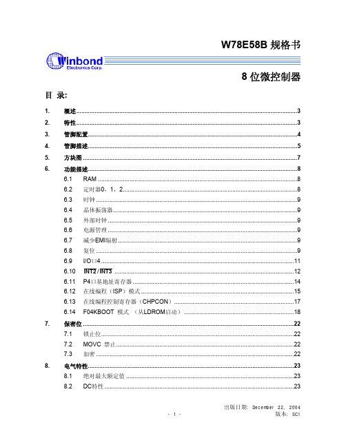
W78E58B规格书8位微控制器目录:1.概述 (3)2.特性 (3)3.管脚配置 (4)4.管脚描述 (5)5.方块图 (7)6.功能描述 (8)6.1 RAM (8)6.2 定时器0,1,2 (8)6.3 时钟 (9)6.4 晶体振荡器 (9)6.5 外部时钟 (9)6.6 电源管理 (9)6.7 减少EMI辐射 (9)6.8 复位 (9)6.9 I/O口4 (11)6.10 INT2/INT3 (12)6.11 P4口基地址寄存器 (14)6.12 在线编程(ISP)模式 (15)6.13 在线编程控制寄存器(CHPCON) (17)6.14 F04KBOOT 模式(从LDROM启动) (18)7.保密位 (22)7.1 锁止位 (22)禁止 (22)7.2 MOVC7.3 加密 (22)8.电气特性 (23)8.1 绝对最大额定值 (23)8.2 DC特性 (23)出版日期: December 22, 20048.3 AC特性 (25)8.3.1时钟输入波形 (25)8.3.2程序读取周期 (26)8.3.3数据读取周期 (26)8.3.4数据写周期 (27)8.3.5端口访问周期 (27)9.时序波形图 (28)9.1 程序读取周期 (28)9.2 数据读周期 (28)9.3 数据写周期 (29)9.4 端口访问周期 (29)10.典型应用电路 (30)10.1 扩展的外部程序存储器和石英晶体 (30)10.2 扩展的外部程序存储器和振荡器 (31)11.封装尺寸 (32)11.1 DIP40 (32)11.2 44 管脚PLCC (33)11.3 44 管脚PQFP (34)12.应用指南 (35)12.1 ISP 软件编程示例: (35)13.文件版本描述 (42)1. 概述W78E58B是具有带ISP功能的Flash EPROM的低功耗8位微控制器;ISP功能的Flash EPROM可用于固件升级。
MITSUBISHI MGFC39V4450A 说明书
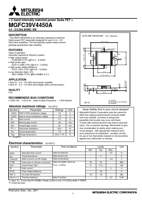
•All information contained in these materials, including product data, diagrams, charts, programs and algorithms represents information on products at the time of publication of these materials, and are subject to change by Mitsubishi Electric Corporation without notice due to product improvements or other reasons. It is therefore recommended that customers contact Mitsubishi Electric Corporation or an authorized Mitsubishi Semiconductor product distributor for the latest product information before purchasing a product listed herein. The information described here may contain technical inaccuracies or typographical errors. Mitsubishi Electric Corporation assumes no responsibility for any damage, liability, or other loss rising from these inaccuracies or errors. Please also pay attention to information published by Mitsubishi Electric Corporation by various means, including the Mitsubishi Semiconductor home page (/).
EM4450中文资料

Reser Data Extractor
Sequencer Command Decoder
Control Logic
Fig. 2
System Principle
Transceiver
Data to be sent to transponder Modulator
Stresses above these listed maximum ratings may cause permanent damages to the device. Exposure beyond specified operating conditions may affect device reliability or cause malfunction.
Operating Conditions
Parameter Operating Temperature Maximum coil current AC Voltage on Coil Supply Frequency Symbol Min Top -40 ICOIL Vcoil fcoil 100 Unit °C mA note 1 Vpp 150 kHz Max +85 10
Applications
Ticketing Automotive Immobilizer with rolling code High Security Hands Free Access Control Industrial automation with portable database Manufacturing automation Prepayment Devices
Typical Operating Configuration
- 1、下载文档前请自行甄别文档内容的完整性,平台不提供额外的编辑、内容补充、找答案等附加服务。
- 2、"仅部分预览"的文档,不可在线预览部分如存在完整性等问题,可反馈申请退款(可完整预览的文档不适用该条件!)。
- 3、如文档侵犯您的权益,请联系客服反馈,我们会尽快为您处理(人工客服工作时间:9:00-18:30)。
Typical Operating Configuration
Coil2 L EM4450 Coil1
Typical value of inductance at 125 kHz is 9.6 mH
Fig.1
Copyright 2003, EM Microelectronic-Marin SA
1
Applications
Ticketing Automotive Immobilizer with rolling code High Security Hands Free Access Control Industrial automation with portable database Manufacturing automation Prepayment Devices
Handling Procedures
This device has built-in protection against high static voltages or electric fields; however, anti-static precautions must be taken as for any other CMOS component. Unless otherwise specified, proper operation can only occur when all terminal voltages are kept within the voltage range. Unused inputs must always be tied to a defined logic voltage level.
Transponder
Oscillator
Antenna Driver
Coil 1
EM4450
Data Decoder Filter & Gain Demodulator Coil 2
Data received from transponder RECEIVE M ODE
Signal on Transponder coil
Reset Write Enable
Clock Extractor Data Extractor
Sequencer Command Decoder
Control Logic
Fig. 2
System Principle
Transceiver
Data to sent to transponder Modulator
Operating Conditions
Parameter Operating Temperature Maximum coil current AC Voltage on Coil Supply Frequency Symbol Min Top -40 ICOIL Vcoil fcoil 100 Unit °C mA note 1 Vpp 150 kHz Max +85 10
Features
1 KBit of EEPROM organized in 32 words of 32 bits 32 bit Device Serial Number (Read Only Laser ROM) 32 bit Device Identification (Read Only Laser ROM) Power-On-Reset sequence Power Check for EEPROM write operation User defined Read Memory Area at Power On User defined Write Inhibited Memory Area User defined Read Protected Memory Area Data Transmission performed by Amplitude Modulation Two Data Rate Options 2 KBd (Opt64) or 4 KBd (Opt32) Bit Period = 64 or 32 periods of field frequency 170 pF ± 2% on chip Resonant Capacitor -40 to +85°C Temperature range 100 to 150 kHz Field Frequency range On chip Rectifier and Voltage Limiter No external supply buffer capacitance needed due to low power consumption Available in chip form for mass production and PCB and CID package for samples.
元器件交易网
EM4450 EM4550
Block Diagram
Modulator
Encoder
ROM EEPROM
+V coil2 coil1 Cr AC/DC converter
Voltage Regulator Cs Pow er Control
READ M ODE
Signal on Transceiver coil
Signal on Transceiver coil Signal on Transponder coil
RF Carrier
Data
RF Carrier
Data
Fig. 3
Copyright 2003, EM Microelectronic-Marin SA
Stresses above these listed maximum ratings may cause permanent damages to the device. Exposure beyond specified operating conditions may affect device reliability or cause malfunction.
note 1: Maximum voltage is defined by forcing 10mA on Coil1 - Coil2.
Electrical Characteristics
VDD =2.5V, VSS =0V , fcoil = 125 kHz Sine wave , Vcoil = 1Vpp , Top = 25°C , unless otherwise specified Parameter Symbol Conditions Min Typ Max Supply Voltage VDD 2.3 3.2 Minimum EEPROM write 2 VDDee voltage Power Check EEPROM write IPWcheck VDD = 2.8V 32 Supply current / read Ird Read Mode 3 Suppy current / write Iwr Write mode (VDD = 2.8V) 22 0.50 V(COIL1 - VSS) & V(COIL2 - VSS) Icoil = 100µA Modulator ON voltage drop VON 2.50 V(COIL1 - VSS) & V(COIL2 - VSS) Icoil = 5 mA Monoflop Tmono 35 85 Resonance Capacitor Cr 166.6 170 173.4 Powercheck level VPWcheck 2 2.7 Power On Reset level high Vprh Rising Supply 1 1.5 Clock extractor input min. Vclkmin Minimum Voltage for Clock Extraction 0.25 25 Vclkmax Clock extractor input max. Max. Voltage to detect modulation stop EEPROM data endurance Ncy Erase all / Write all at VDD = 3.5 V 100'000 EEPROM retention Tret Top = 55°C after 100'000 cycles (note 2) 10 note 2: Based on 1000 hours at 150°C Unit V V µA µA µA V V µs pF V V Vpp mVpp cycles years
2
元器件交易网
EM4450 EM4550
Absolute Maximum Ratings
Parameter Symbol Maximum AC peak Current ICOIL induced on COIL1 and COIL2 Power Supply VDD Vmax Maximum Voltage other pads Vmin Minimum Voltage other pads Storage temperature Tstore Electrostatic discharge maximum VESD to MIL-STD-883C method 3015 Conditions ± 30 mA -0.3 to 3.5 V VDD+0.3V VSS-0.3V -55 to +125°C 2000V
元器件交易网
EM MICROELECTRONIC - MARIN SA
EM4450 EM4550
1 KBit Read/Write Contactless Identification Device
Description
The EM4450/4550 is a CMOS integrated circuit intended for use in electronic Read/Write RF Transponders. The difference between EM4450 and EM4550 is that EM4550 are bumped and has megapads for the two coils. The chip contains 1 KBit of EEPROM which can be configured by the user, allowing a write inhibited area, a read protected area, and a read area output continuously at power on. The memory can be secured by using the 32 bit password for all write and read protected operations. The password can be updated, but never read. The fixed code serial number and device identification are laser programmed making every chip unique. The EM4450/4550 will transmit data to the transceiver by modulating the amplitude of the electromagnetic field, and receive data and commands in a similar way. Simple commands will enable to write EEPROM, to update the password, to read a specific memory area, and to reset the logic. The coil of the tuned circuit is the only external component required, all remaining functions are integrated in the chip.
