WJ1141CS106VDC5.0中文资料
全系列产品电子样本
上海奉申制冷控制器有限公司
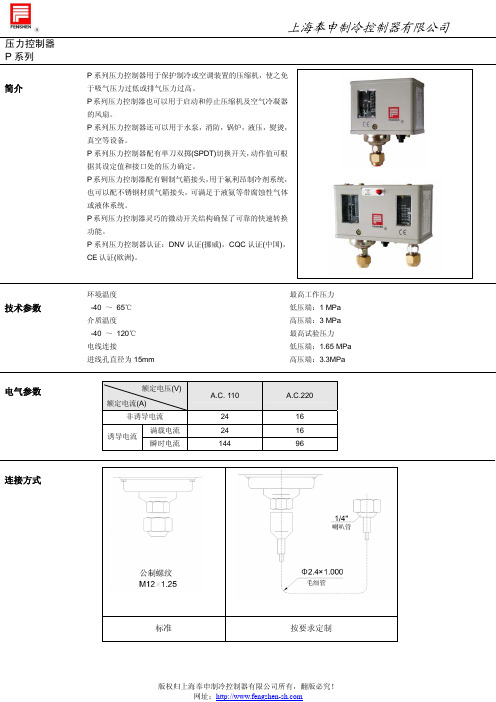
MP45 系列小型压力控制器是一种用压力信号来控制的电开关,它是以压缩机的排气压力 为动作信号来控制压缩机的启停,当压缩机的排气压力超过调定值时,切断电源,起到压 力保护作用。
型号说明
型号
MP45
F
01
B
11
D
3
T
2.6
说明
型号代码 MP45M 为手动复 位形式
连接形式 代号 W
额定电压(V)
额定电流(A) 非诱导电流
诱导电流
满载电流 瞬时电流
A.C. 110
24 24 144
A.C.220
16 16 96
○1 : 公共触点 ○1 -○3 : 温度上升时闭合 ○1 -○5 :温度下降时闭合
↑M: 手动复位方向
版权归上海奉申制冷控制器有限公司所有,翻版必究! 网址:
自动
1.2 1.05
0.5→3.0 0.5→3.0
0.50~1.0 0.3~0.5
固定
自动 自动
2.0 1.5 2.0 1.5
0.5→3.0 固定≥0.4
手动
2.0 ≤1.6
0.3~0.5
0.5→3.0
自动 自动 0.3 0.2 2.0 1.5
固定
0.5→3.0 固定≥0.4 自动 手动 0.3 0.2 2.0 ≤1.6
标准附件及尺寸
版权归上海奉申制冷控制器有限公司所有,翻版必究! 网址:
压力控制器 P 系列
触点形式
形式
低压
型号 P2,P3,P6,P10
P6M
复位形式 自动 手动
P12D,P16D,P20D,P30D
自动
上海奉申制冷控制器有限公司
ZSSC3135AA2T中文资料(ZMDI)中文数据手册「EasyDatasheet - 矽搜」

数据表
修订1.00 2011 /月
ZSSC3135
传感器信号调理器,用于压阻式桥传感器
芯片中文手册,看全文,戳
ZSSC3135
传感器信号调理器,用于压阻式桥传感器
简 要 描 述 ;简 介
所述ZSSC3135是ZSSC313x成员 CMOS产品系列集成电路 专为汽车/工业传感器应用 系统蒸发散.所有家人都非常适合highly-
2电路描述....................................................................................................................................... 11 2.1.信号流........................................................................................................................................... 11 2.2.应用模式................................................................................................................................ 12 2.3.模拟前端(AFE) ....................................................................................................................... 12 2.3.1.可编程增益放大器(PGA)............................................ ................................................. 12 2.3.2.偏移补偿..................................................................................................................... 13 2.3.3.测量周期....................................................................................................................... 13 2.3.4.模拟 - 数字转换器............................................................................................................ 15 2.4.温度测量.................................................................................................................. 16 2.5.系统控制和调节计算............................................. ......................................... 16 2.5.1.操作Modes............................................................................................................................ 16 2.5.2.启动阶段................................................................................................................................ 16 2.5.3.空调计算................................................................................................................ 17 2.6.模拟输出AOUT ............................................................................................................................ 17 2.7.串行数字接口.......................................................................................................................... 18 2.8.故障防护护功能,看门狗和错误检测........................................... .................................... 18 2.9.高电压,反向极性防护护和短路防护护......................................... ...................... 18
CF500 中文手册

102576_ia_02
P 子公司 发布单位:
法律权利声明 本手册,包括其中的所有插图,都受到版权保护。禁止任何第三方使用本手册。对本 手册进行复制、翻译、公开展示以电子/照相形式存档或改编需要得到菲尼克斯电气 有限公司的书面同意, 违者将对所有损失负责。 菲尼克斯电气有限公司在专利授权或注册设计编目情况下保留所有权利。第三方产品 的命名不得引用我方专利权。不得排除此类专利权的存在性。
本手册用户群 本手册中所述的产品,仅可由具有资质的电气工程师、以及接受其指导的操作人员使 用,这些人员熟悉适用的标准及其它电气工程规定,特别是相关的安全概念。 对于无视本手册中的信息而造成对菲尼克斯电气有限公司或第三方公司产品的错误操作 或损坏,菲尼克斯电气有限公司概不负责。
所用符号及标志用词解释
此为安全特别注意符号! 此符号用于提醒您注意潜在的人身伤害危险。请 遵守此项特别注意符号标示的所有安全迅息,以避免可能导致的伤亡危险。
尽管菲尼克斯电气有限公司作出一切努力来确保信息内容的精确性、最新性, 并反映出最新技术发展,但是信息中难免会存在技术的不精确性以及(或者)印刷 错误。菲尼克斯电气有限公司并不对信息的可靠性、精确性或完整性作出保证。不 管是明确提及、暗示或者默认的方式,技术数据中提供的所有信息并不附随保证。 这些信息并不包括有关质量作出任何保证,不对任何合理可销质量进行描述,亦不 对质量保证或者对适用于特殊目的的保证作出任何要求。
如果您对于本公司手册的内容和编排方面有任何改进意见或建议,请发送邮件至: tecdoc@。
PHOENIX CONTACT
102576_ia_02
Engli sh
中文版
目录
1......基本说明 ...........................................................................................................................................................1-1 1.1......这是为了确保您自身的安全 ........................................................................................................................1-1 1.2......机器可能造成的危险 ....................................................................................................................................1-1 1.3......正确使用设备 ................................................................................................................................................1-2 1.4......工作场所..........................................................................................................................................................1-2 1.5......防护装置..........................................................................................................................................................1-2 1.6......授权操作人员 ................................................................................................................................................1-3 1.7......保证 ................................................................................................................................................................1-3
密度继电器检测-测试仪

前言感谢您使用武汉恒新国仪科技有限公司的产品,GYCS型全自动SF6密度继电器检测仪是本公司历时四年独立开发研制的高精密仪器,仪器关键器件全部采用原装进口件,通过高精度压力传感器及高精度A/D、D/A转换器,结合高性能十六位单片机,能自动完成对SF6密度继电器的检测,能准确测量信号动作时当前温度下的压力值并自动完成20 C值的换算,能自动打印试验数据并自动存储以备查阅。
仪器具有高精度,高稳定性,高可靠性的特点。
请您在使用之前仔细阅读使用说明书并按步骤操作。
目录概述 (3)●进行密度继电器检测的必要性 (3)●进行SF6密度继电器检测基本原理 (3)● GYCS型密度继电器检测仪功能特点: (4)技术指标 (5)使用方法 (6)准备工作 (6)密度继电器检测 (7)℃压力表检测 (9)系统压力值修正 (11)系统时钟调整 (11)历史数据浏览 (12)结束工作 (13)注意事项 (13)保管和运输 (14)产品售后服务 (14)附录一 (15)附录二 (16)附录三 (17)装箱清单 (18)●进行密度继电器检测的必要性SF6开关是电力系统广泛使用的高压电器。
SF6开关的可靠运行已成为供用电部门最关心的问题之一。
SF6气体密度继电器是用来监测运行中SF6开关本体中SF6气体密度变化的重要元件,其性能的好坏直接影响到SF6开关的运行安全。
现场运行的SF6气体密度继电器因不常动作,经过一段时期后常出现动作不灵活、触点接触不良等现象,有的还会出现密度继电器温度补偿性能变差,当环境温度突变时常导致SF6密度继电器误动作。
因此DL/T596-1996《电力设备预防性试验规程》规定:各SF6开关使用单位应定期对SF6气体密度继电器进行检测。
从实际运行情况看,对现场运行中的SF6密度继电器、压力表进行定期检测也是非常必要的。
●进行SF6密度继电器检测基本原理密闭容器中的气体压力随温度的变化而变化,为了便于统计和比较,通常把20℃时的SF6的相对压力值作为标准值。
GF仪表中文说明
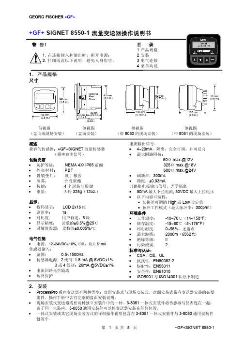
3. 将安装支架从仪表后面推上,直到快速固定卡片卡入仪表两 侧的槽中
4. 拆卸仪表时,在盘前用胶带暂时将仪表挡好,或在后部抓 牢。不要让仪表掉落。向外侧撑开快速固定卡片,抽出仪表 即可。
盘面安装详解
3. 电气连接
注意:在拆除接线之前如果没有将端子插孔完全打开,可能会永久地损坏仪表。
• 一体式安装或其它现场安装方式的详细操作说明包含在 3-8051 一体式安装件与 3-8050 通用安装件 包装中。
第 1 页共 8 页
+GF+SIGNET 8550-1
GEORG FISCHER +GF+
2.1 盘面安装
1. 盘装变送器需要一个 1/4DIN 开孔器。同时提供一张不干胶 模板,作为人工开孔时的安装指导。建议仪表各侧保留 1in.(25mm)的净边距。
3.2 传感器输入连接 接线提示
• 不要将传感器的电缆与 AC 电缆敷设在同一根电缆导管内。电子噪音会干扰传感器信号。 • 将电缆敷设在接地的金属电缆管中有助于防止电子噪音与机械损伤。 • 将电缆入口处密封,以防潮汽的侵害。 • 每个端子只能插入一根导线。如果两根导线接入同一端子,要在外部连好。
对于 515/8510-XX,525,2517,以及任何输出正弦波信号的传 感器,最大电缆长度为 200ft(61m)。
• Pulse 根据通过传感器的流量体积量,发出一个脉冲 信号。设定的体积量范围为 0.0001~99999。
设为 OFF 状态时,此项输出被隐藏。
输出信号被激励 输出信号复位
视图菜单(VIEW)
• 正常运行时,ProcessPro 系列仪表处于视图菜单(VIEW)显示状态。 • 在使用标定菜单(CALIBRATE)或选项菜单(OPTIONS)时,如果超过 10 分
海康威视总线制报警主机操作手册

3.1 总线式网络报警主机启动 ...................................................................................................... 20 3.2 报警键盘启动 .......................................................................................................................... 20 3.3 键盘编址 .................................................................................................................................. 20 3.4 出厂设置 .................................................................................................................................. 21
工作状态指示灯 网络状态指示灯 电源指示灯
GPRS模块
SIM卡槽
D+ D- +12V G
COM1
COM2
COM3
COM4
1410965-1中文资料

1410965-1 Product DetailsHome | Customer Support | Suppliers | Site Map | Privacy Policy | Browser Support© 2008 Tyco Electronics Corporation All Rights Reserved SearchProducts Documentation Resources My Account Customer SupportHome > Products > By Type > Two-Piece, High-Speed Connectors > Product Feature Selector > Product Details1410965-1Active MULTIGIG RT ProductAlways EU RoHS compliant but not ELV Compliant(Statement of Compliance)Product Highlights:?Backplane?RT2 Series?VITA 41/VITA 46 Configuration?Spacing Between Cards = 20.30 mm?Module Type = CenterView all Features | Find SimilarProductsCheck Pricing &AvailabilitySearch for ToolingProduct FeatureSelectorContact Us AboutThis ProductQuick LinksDocumentation & Additional InformationProduct Drawings:?CONNECTOR ASSEMBLY,BACKPLANE VERTICAL RECEPTACLE,CE...(PDF, English)Catalog Pages/Data Sheets:?None AvailableProduct Specifications:?None AvailableApplication Specifications:?None AvailableInstruction Sheets:?None AvailableCAD Files: (CAD Format & Compression Information)?2D Drawing (DXF, Version A)?3D Model (IGES, Version A)?3D Model (STEP, Version A)List all Documents Additional Information:?Product Line InformationRelated Products:?ToolingProduct Features (Please use the Product Drawing for all design activity)Product Type Features:?Product Type = Backplane?Mount Angle = Vertical?Comment = Connector J5 will use connector J6when physical position of J6 is either not beingused or a connector other than MULTIGIG RT isin this position such as a FO connector. Mechanical Attachment:?Module Type = CenterElectrical Characteristics:?Data Rate (Gb/s) = 6.500Termination Related Features:?Solder Tail Contact Plating = Tin-Lead overNickelBody Related Features:?Series = RT2?Number of Columns = 16?Flammability Rating = UL 94V-0 Contact Related Features:?Spacing Between Cards (mm [in]) = 20.30[0.800]?Contact Material = Phosphor Bronze?Contact Mating Area Plating = Gold over Nickel Housing Related Features:?Housing Material = Liquid Crystal Polymer(LCP)?Housing Color = BlackConfiguration Related Features:?Density = 85 lines/inchIndustry Standards:?RoHS/ELV Compliance = RoHS/Not ELVCompliant?Lead Free Solder Processes = Not relevant forlead free process?VITA 41/VITA 46 Configuration = Yes?RoHS/ELV Compliance History = Always wasRoHS not ELV compliantOther:?Brand = Tyco ElectronicsProvide Website Feedback | Contact Customer Support。
产品管理-魏德米勒继电器产品详细目录
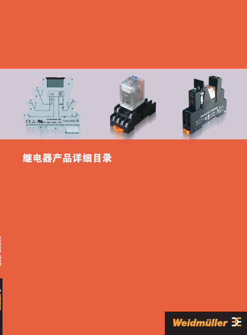
继电器产品目 录光电耦合器产品电子式时间继电器功能电子产品通讯电子产品250V/6A 12V/100mA 6.2ms/3.9ms AgSnO 2 20x106 次 0.1Hz LED 绿色/有/有 -25 °C…+55 °C -40 °C…+60 °C 40°C/93% 湿度无冷凝 CE, cURus EN 50178 300 V 4 kV ≥5.5mm III 2 是 mm 2 mm 2.5 / 0.5 / 4 1.5 / 0.5 / 2.5 93.0 / 6.1 / 92.094.0 / 6.1 / 91.0 电压 [A ] 电流 [A] 电流 [A] 电流 [A]acc.to DC 13 输出参数应用额定参数绝缘基座参数 (EN 50 178)尺寸螺钉连接弹片连接最大切换电压AC/电流 最小切换电压/电流响应时间/释放时间 触点材料 机械寿命 额定负载下的最大开关频率 状态指示/二极管/反向电压保护环境工作温度存储温度环境温度认证标准额定电压额定浪涌电压接点间爬电距离过压等级污染等级符合VDE 0106 101安全隔离 接线范围(额定/最小/最大) 长x 宽x 高负载特性曲线开关次数 开关次数1对转换触点· 该继电器可用于联接控制信号与执行器· 插拔式横联可减少联线· 6.1mm 厚· 可采用弹片式或压线框联接· 可提供镀金触头继电器(感性负载)1继电器5mA4mA190mW29V/11V29V/11V2.2mA/1.3mA2.2mA/1.3mAMRZ 48Vuc 1CO8556110000RSS 113048 48Vdc-Rel1U40616200003.3mA200mW35V/11V1.6mA/0.6mAMRZ 60Vdc 1CO8556130000RSS 113060 60Vdc-Rel1U40616300003.5mA3.5mA0.42mW71V/22V71V/22V1.8mA/0.5mA1.8mA/0.5mAMRZ 120Vuc 1CO8556100000RSS 113060 60Vdc-Rel1U40616300007.6mA1.75VA103V/49V5mA/2.5mAMRZ 230Vac 1CO8556090000RSS 113024 24Vdc-Rel1U4060120000螺钉连接型号订货号弹片连接型号订货号型号订货号38.5mA193mW3.2V/1.6V21.6mA/8mAMRZ 5Vdc 1CO8556150000RSS 113005 05Vdc-Rel1U406158000017mA210mW6.4V/2.5V8.4mA/2.4mAMRZ 12Vdc 1CO8556140000RSS 113012 12Vdc-Rel1U40616100006.6mA160mW15.4V/6.5V4mA/1.2mAMRZ 24VDC 1CO853*******RSS 113024 24Vdc-Rel1U406012000011mA6.4mA154mW15.8V/7V15.8V/7V3.6mA/1.3mA3.6mA/1.3mAMRZ 24Vuc 1CO8556120000RSS 113024 24Vdc-Rel1U4060120000 订货数据订货数据配件,插拔式继电器订货数据输入额定电压额定电流AC额定电流DC额定功率动作/释放电压AC 线圈动作/释放电压DC 线圈动作/释放电流AC 线圈动作/释放电流DC 线圈螺钉连接型号订货号弹片连接型号订货号型号订货号订货数据订货数据配件,插拔式继电器订货数据输入额定电压额定电流AC额定电流DC额定功率动作/释放电压AC 线圈动作/释放电压DC 线圈动作/释放电流AC 线圈动作/释放电流DC线圈6.6mA160mW15.4V/6.5V4mA/1.2mAMRZ 24Vdc ACT8660910000RSS 113024 24Vdc-Rel1U40601200007mA0.84VA79V/65V4.5mA/3.7mA15.6mA3.59VA117.5V/59V9.13mA/4.78mAMRZ 120Vac 1CO RC8825960000RSS 113060 60Vdc-Rel1U4061630000螺钉连接型号订货号弹片连接型号订货号型号订货号订货数据订货数据配件,插拔式继电器订货数据特殊产品输入额定电压额定电流AC额定电流DC额定功率动作/释放电压AC线圈动作/释放电压DC 线圈动作/释放电流AC 线圈动作/释放电流DC 线圈3.5mA2.5mA0.8VA /600MW146V/124V155V/1.5V1.9mA/1.5mA1.9mA/1.0mAMRZ 230Vuc 1CO8825980000RSS 113060 60Vdc-Rel1U40616300002继电器RSS 113024 24Vdc-Rel1U40601200002个转换触点250V/6A12V/10mA7ms/3msAgNi20x106次0.1HzLED 绿色/有/有-25 °C…+60 °C-40 °C…+80 °C5%...95% 湿度无冷凝CEEN 50178300 V4 kV≥5.5mmIII2是mm2mm2.5 / 0.5 / 494.2 / 14 / 94.016.7mA500mW16.8V/2.4V3.2mA0.75VA172.5V/34.5V订货数据· 该继电器可用于联接控制信号与执行器· 插拔式横联可减少联线· 14mm厚· 采用弹片式联接输出参数额定参数绝缘基座参数 (EN 50 178)尺寸弹片连接最大切换电压AC/电流最小切换电压/电流响应时间/释放时间触点材料机械寿命额定负载下的最大开关频率状态指示/二极管/反向电压保护环境工作温度存储温度环境温度认证标准额定电压额定浪涌电压接点间爬电距离过压等级污染等级符合VDE 0106 101安全隔离接线范围(额定/最小/最大)长x宽x高弹片连接型号订货号订货数据输入额定电压额定电流AC额定电流DC额定功率动作/释放电压AC 线圈动作/释放电压DC 线圈动作/释放电流AC 线圈动作/释放电流DC 线圈3继电器· 该继电器可用于联接控制信号与执行器· 插拔式横联可减少联线· 14mm厚· 采用弹片式联接250V/6A(输出并联可达10A)12V/10mA7ms/3msAgNi20x106次0.1HzLED 绿色/有/有-25 °C…+60 °C-40 °C…+80 °C5%...95% 湿度无冷凝CEEN 50178300 V4 kV≥5.5mmIII2是mm2mm2.5 / 0.5 / 494.2 / 14 / 94.016.7mA500mW16.8V/2.4V3.2mA0.75VA172.5V/34.5V订货数据输出参数额定参数绝缘基座参数 (EN 50 178)尺寸弹片连接最大切换电压AC/电流最小切换电压/电流响应时间/释放时间触点材料机械寿命额定负载下的最大开关频率状态指示/二极管/反向电压保护环境工作温度存储温度环境温度认证标准额定电压额定浪涌电压接点间爬电距离过压等级污染等级符合VDE 0106 101安全隔离接线范围(额定/最小/最大)长x宽x高弹片连接型号订货号订货数据输入额定电压额定电流AC额定电流DC额定功率动作/释放电压AC 线圈动作/释放电压DC 线圈动作/释放电流AC 线圈动作/释放电流DC 线圈4继电器250V/6A12V/10mA6.6ms/5.8msAgSnO2 5μm Au20x106次0.1HzLED 绿色/有/有-25 °C…+55 °C-40 °C…+60 °C40°C/93% 湿度无冷凝CE, cURusEN 50178300 V4 kV≥5.5mmIII2是mm2mm2.5 / 0.5 / 4 1.5 / 0.5 / 2.593.0 / 6.1 / 92.094.0 / 6.1 / 91.06.6mA160mW15.4V/6.5V4mA/1.2mAMRZ 24Vdc 1CO 5uAu8596080000RSS 112024 24Vdc-Rel1U40615900003.5mA3.5mA0.42VA71V/22V71V/22V1.8mA/0.5mA1.8mA/0.5mAMRZ 120Vuc 1CO 5uAu8652040000RSS 112060 60Vdc-Rel1U40616000007.6mA1.75VA103V/49V5mA/2.5mAMRZ 230Vac 1CO 5uAu8596070000RSS 112024 24Vdc-Rel1U4061590000订货数据· 该继电器可用于联接控制信号与执行器· 插拔式横联可减少联线· 6.1mm厚· 可采用弹片式或压线框联接· 可提供镀金触头继电器输出参数额定参数绝缘基座参数 (EN 50 178)尺寸螺钉连接弹片连接最大切换电压AC/电流最小切换电压/电流响应时间/释放时间触点材料机械寿命额定负载下的最大开关频率状态指示/二极管/反向电压保护环境工作温度存储温度环境温度认证标准额定电压额定浪涌电压接点间爬电距离过压等级污染等级符合VDE 0106 101安全隔离接线范围(额定/最小/最大)长x宽x高螺钉连接型号订货号弹片连接型号订货号型号订货号订货数据订货数据配件,插拔式继电器输入额定电压额定电流AC额定电流DC额定功率动作/释放电压AC 线圈动作/释放电压DC 线圈动作/释放电流AC 线圈动作/释放电流DC 线圈5继电器该继电器可用于连接控制信号和执行器,适用于中小型负载继电器横块可更换6.1 mm厚插拔式横联件可减少接线Cl.1 Div.2区域的防爆认证••••技术参数6光电耦合器该继电器可用于连接控制信号和执行器,适用于中小型负载继电器横块可更换6.1 mm厚插拔式横联件可减少接线Cl.1 Div.2区域的防爆认证120 VAC的继电器RC组合模块,输入端的RC组合电路可以保证安全切换,例如可防止漏电流的影响。
CS8122YTVA5G中文资料

CS81222.0% 5.0 V, 750 mA Low Dropout Linear Regulator with Delayed RESETThe CS8122 is a precision 5.0 V linear regulator capable of sourcing in excess of 750 mA. The RESET’s delay time is externallyprogrammed using a discrete RC network. During power up, or when the output goes out of regulation, the RESET lead remains in the low state for the duration of the delay. This function is independent of the input voltage and will function correctly as long as the output voltage remains at or above 1.0 V. Hysteresis is included in the Delay and the RESET comparators to improve noise immunity. A latching discharge circuit is used to discharge the delay capacitor when it is triggered by a brief fault condition.The regulator is protected against a variety of fault conditions: i.e. reverse battery, overvoltage, short circuit and thermal runaway conditions. The regulator is protected against voltage transients ranging from −50 V to +40 V. Short circuit current is limited to 1.2 A (typ). The CS8122 is an improved replacement for the CS8126 and features a tighter tolerance on its output voltage (2.0% vs. 4.0%). The CS8122 is packaged in a 5 lead TO−220 with copper tab. The copper tab can be connected to a heat sink if necessary.Features•5.0 V ±2.0% Regulated Output•Low Dropout V oltage (0.6 V @ 0.5 A)•750 mA Output Current Capability•Externally Programmed RESET Delay•Fault Protection−Reverse Battery−60 V Load Dump−−50 V Reverse Transient−Short Circuit−Thermal Shutdown•Pb−Free Packages are Available**For additional information on our Pb−Free strategy and soldering details, please download the ON Semiconductor Soldering and Mounting Techniques Reference Manual, SOLDERRM/D.TO−220FIVE LEADTVA SUFFIXCASE 314KTO−220FIVE LEADTHA SUFFIXCASE 314AMARKING DIAGRAMSTO−220 5−LEADA = Assembly Location WL = Wafer Lot Y = YearWW = Work WeekG= Pb−Free PackageCS 8122AWLYWWG1CS8122AWLYWWG 1CS8122AWL YWWG1CASE 314D CASE 314K CASE 314AGNDFigure 1. Block DiagramDelayABSOLUTE MAXIMUM RATINGSRating Value Unit Input Operating Range−0.5 to 26V Power Dissipation Internally Limited−Peak Transient Voltage (46 V Load Dump @ V IN = 14 V)−50, 60V Output Current Internally Limited−Electrostatic Discharge (Human Body Model) 4.0kV Junction Temperature−55 to +150°C Storage Temperature Range−55 to +150°C Lead Temperature Soldering Wave Solder (through hole styles only) (Note 1)260 peak°C Stresses exceeding Maximum Ratings may damage the device. Maximum Ratings are stress ratings only. Functional operation above the Recommended Operating Conditions is not implied. Extended exposure to stresses above the Recommended Operating Conditions may affect device reliability.1.10−second maximum.ELECTRICAL CHARACTERISTICS (−40°C ≤ T A≤125°C, −40 ≤ T J≤150°C, 6.0 ≤ V IN≤26 V, 5.0 mA ≤ I OUT≤500 mA,R RESET = 4.7 k W to V CC unless otherwise noted.) (Note 2)Characteristic Test Conditions Min Typ Max Unit OUTPUT STAGE (V OUT)Output Voltage− 4.9 5.0 5.1V Dropout Voltage I OUT = 500 mA−0.350.60VSupply Current I OUT≤ 10 mAI OUT≤ 100 mAI OUT≤ 500 mA −−−2.06.0557.012100mAmAmALine Regulation 6.0 V ≤ V IN≤ 26 V, I OUT= 50 mA− 5.050mV Load Regulation50 mA ≤I OUT≤500 mA, V IN = 14 V−1050mV Ripple Rejection f = 120 Hz, 7.0 ≤ V IN≤ 17 V, I OUT = 250 mA5475−dB Current Limit−0.75 1.20−A Overvoltage Shutdown−32−40V Maximum Line Transient V OUT≤ 5.5 V6095−V Reverse Polarity Input Voltage DC V OUT≥ −0.6 V, 10 W Load−15−30−V Reverse Polarity Input Voltage Transient 1.0% Duty Cycle, T < 100 ms, 10 W Load−50−80−V Thermal Shutdown Guaranteed by Design150180210°C RESET AND DELAY FUNCTIONSDelay Charge Current V DELAY = 2.0 V 5.01015m ARESET Threshold VOUT Increasing, V RT(ON)V OUT Decreasing, V RT(OFF)4.654.504.904.70V OUT − 0.01V OUT − 0.16VVRESET Hysteresis V RH = V RT(ON) − V RT(OFF)150200250mVDelay Threshold Charge, V DC(HI)Discharge, V DC(L)3.252.853.503.103.753.35VVDelay Hysteresis−200400800mV RESET Output Voltage Low 1.0 V < V OUT < V RT(L), 3.0 k W to V OUT−0.10.4V RESET Output Leakage V OUT > V RT(H)0−10m A Delay Capacitor Discharge Voltage Discharge Latched “ON”, V OUT > V RT−0.20.5V Delay Time C DELAY = 0.1 m F163248ms 2.To observe safe operating junction temperatures, low duty cycle pulse testing is used in tests where applicable.Delay Time+C Delay V Delay Threshold ChargeI Charge+C Delay 3.5105(typ)PACKAGE LEAD DESCRIPTIONPACKAGE LEAD #TO−220 5 LEADLEAD SYMBOLFUNCTION1V IN Unregulated supply voltage to IC.2V OUT Regulated 5.0 V output.3GND Ground Connection.4Delay Timing capacitor for RESET function.5RESETCMOS/TTL compatible output lead. RESET goes low whenever V OUT drops below 6.0% of it’s regulated value.TYPICAL PERFORMANCE CHARACTERISTICSV IN (V)Figure 2. Quiescent Current vs. Input VoltageOver Temperature302520151050Q u i e s c e n t C u r r e n t (m A )Figure 3. Quiescent Current vs. InputVoltage Over Load ResistanceV IN (V )1201000Q u i e s c e n t C u r r e n t . (m A )806040203540455055Figure 4. Output Voltage vs. Input VoltageOver TemperatureFigure 5. V OUT vs. V IN Over R LOADV IN (V)01234681053.02.52.01.51.00.50V O U T (V )93.54.04.55.05.57V IN (V)1234681053.02.52.01.51.00.5V O U T (V )93.54.04.55.05.57TYPICAL PERFORMANCE CHARACTERISTICSOutput Current (mA)800100200700300400804020−20600−100L i n e R e g . (m V )600500Output Current (mA)6004003002001000D r o p o u t V o l t a g e (m V )500700Frequency (Hz)10101010101070504030200R e j e c t i o n (d B )60101010108090−80−60−401000800100200700300400600500800900Output Current (mA)10101010Figure 6. Line Regulation vs. Output CurrentFigure 7. Load Regulation vs. Output CurrentFigure 10. Ripple RejectionFigure 11. Output Capacitor ESRFigure 12. RESET Circuit WaveformCIRCUIT DESCRIPTIONThe CS8122 RESET function, has hysteresis on both the reset and delay comparators, a latching Delay capacitor discharge circuit, and operates down to 1.0 V.The RESET circuit output is an open collector type with ON and OFF parameters as specified. The RESET output NPN transistor is controlled by the two circuits described (see Block Diagram on page 2).Low Voltage Inhibit CircuitThe Low V oltage Inhibit Circuit monitors output voltage, and when output voltage is below the specified minimum, causes the RESET output transistor to be in the ON (saturation) state. When the output voltage is above the specified level, this circuit permits the RESET output transistor to go into the OFF state if allowed by the RESET Delay circuit.Reset Delay CircuitThe Reset Delay Circuit provides a programmable (by external capacitor) delay on the RESET output lead. The Delay lead provides source current to the external delay capacitor only when the Low V oltage Inhibit circuit indicates that output voltage is above V RT(ON). Otherwise, the Delay lead sinks current to ground (used to discharge the delay capacitor). The discharge current is latched ON when the output voltage is below V RT(OFF). The Delay capacitor is fully discharged anytime the output voltage falls out of regulation, even for a short period of time. This feature ensures that a controlled RESET pulse is generated following detection of an error condition. The circuit allows the RESET output transistor to go to the OFF (open) state only when the voltage on the Delay lead is higher than V DC(HI).Figure 13. Test Circuit*C IN is required if regulator is far from the power source filter.**C OUT is required for stability.APPLICATION NOTESSTABILITY CONSIDERATIONSThe output or compensation capacitor, C OUT, helps determine three main characteristics of a linear regulator: start−up delay, load transient response and loop stability. The capacitor value and type should be based on cost, availability, size and temperature constraints. A tantalum or aluminum electrolytic capacitor is best, since a film or ceramic capacitor with almost zero ESR can cause instability. The aluminum electrolytic capacitor is the least expensive solution, but, if the circuit operates at low temperatures (−25°C to −40°C), both the value and ESR of the capacitor will vary considerably. The capacitor manufacturers data sheet usually provides this information. The value for the output capacitor C OUT shown in Figure 13 should work for most applications, however it is not necessarily the optimized solution.To determine an acceptable value for C OUT for a particular application, start with a tantalum capacitor of the recommended value and work towards a less expensive alternative part.Step 1: Place the completed circuit with a tantalum capacitor of the recommended value in an environmental chamber at the lowest specified operating temperature and monitor the outputs with an oscilloscope. A decade box connected in series with the capacitor will simulate the higher ESR of an aluminum capacitor. Leave the decade box outside the chamber, the small resistance added by the longer leads is negligible.Step 2: With the input voltage at its maximum value, increase the load current slowly from zero to full load while observing the output for any oscillations. If no oscillations are observed, the capacitor is large enough to ensure a stable design under steady state conditions.Step 3: Increase the ESR of the capacitor from zero using the decade box and vary the load current until oscillations appear. Record the values of load current and ESR that cause the greatest oscillation. This represents the worst case load conditions for the regulator at low temperature.Step 4: Maintain the worst case load conditions set in step 3 and vary the input voltage until the oscillations increase. This point represents the worst case input voltage conditions.Step 5: If the capacitor is adequate, repeat steps 3 and 4 with the next smaller valued capacitor. A smaller capacitor will usually cost less and occupy less board space. If the output oscillates within the range of expected operating conditions, repeat steps 3 and 4 with the next larger standard capacitor value.Step 6: Test the load transient response by switching in various loads at several frequencies to simulate its real working environment. Vary the ESR to reduce ringing. Step 7: Raise the temperature to the highest specified operating temperature. Vary the load current as instructed in step 5 to test for any oscillations.Once the minimum capacitor value with the maximum ESR is found, a safety factor should be added to allow for the tolerance of the capacitor and any variations in regulator performance. Most good quality aluminum electrolytic capacitors have a tolerance of ± 20% so the minimum value found should be increased by at least 50% to allow for this tolerance plus the variation which will occur at low temperatures. The ESR of the capacitor should be less than 50% of the maximum allowable ESR found in step 3 above. CALCULATING POWER DISSIPATION IN A SINGLEOUTPUT LINEAR REGULATORThe maximum power dissipation for a single output regulator (Figure 14) is:P D(max)+NJV IN(max)*V OUT(min)NjI OUT(max))V IN(max)I Q(1) where:V IN(max) is the maximum input voltage,V OUT(min) is the minimum output voltage,I OUT(max) is the maximum output current for theapplication, andI Q is the quiescent current the regulator consumes atI OUT(max).Once the value of P D(max) is known, the maximum permissible value of R q JA can be calculated:R q JA+150°C*T AP D(2) The value of R q JA can then be compared with those in the package section of the data sheet. Those packages with R q JA’s less than the calculated value in equation 2 will keep the die temperature below 150°C.In some cases, none of the packages will be sufficient to dissipate the heat generated by the IC, and an external heatsink will be required.Figure 14. Single Output Regulator With KeyPerformance Parameters LabeledV IN V OUTHEAT SINKSA heat sink effectively increases the surface area of the package to improve the flow of heat away from the IC and into the surrounding air.Each material in the heat flow path between the IC and the outside environment will have a thermal resistance. Like series electrical resistances, these resistances are summed to determine the value of R q JA .R q JA +R q JC )R q CS )R q SA(3)where:R q JC = the junction−to−case thermal resistance,R q CS = the case−to−heatsink thermal resistance, and R q SA = the heatsink−to−ambient thermal resistance.R q JC appears in the package section of the data sheet. Like R q JA , it too is a function of package type. R q CS and R q SA are functions of the package type, heatsink and the interface between them. These values appear in heat sink data sheets of heat sink manufacturers.ORDERING INFORMATIONDevicePackage ShippingCS8122YT5TO−220STRAIGHT 50 Units / Rail CS8122YT5GTO−220STRAIGHT (Pb−Free)CS8122YTVA5TO−220VERTICAL CS8122YTVA5GTO−220VERTICAL (Pb−Free)CS8122YTHA5TO−220HORIZONTAL CS8122YTHA5GTO−220HORIZONTAL (Pb−Free)PACKAGE DIMENSIONSTO−220CASE 314D−04ISSUE FDETAIL A−ATO−220TVA SUFFIX CASE 314K−01ISSUE ONOTES:1.DIMENSIONING AND TOLERANCING PER ANSIY14.5M, 1982.2.CONTROLLING DIMENSION: INCH.3.DIMENSION D DOES NOT INCLUDEINTERCONNECT BAR (DAMBAR) PROTRUSION.DIMENSION D INCLUDING PROTRUSION SHALL NOT EXCEED 10.92 (0.043) MAXIMUM.DIM MIN MAX MIN MAX MILLIMETERS INCHES A 0.5600.59014.2214.99B 0.3850.4159.7810.54C 0.1600.190 4.06 4.83D 0.0270.0370.690.94E 0.0450.055 1.14 1.40F 0.5300.54513.4613.84G 0.067 BSC 1.70 BSC J 0.0140.0220.360.56K 0.7850.80019.9420.32L 0.3210.3378.158.56M 0.0630.078 1.60 1.98Q 0.1460.156 3.71 3.96S 0.1460.196 3.71 4.98U 0.4600.47511.6812.07W55°°R 0.2710.321 6.888.15PACKAGE DIMENSIONSTO−220THA SUFFIX CASE 314A−03ISSUE EPACKAGE THERMAL DATAParameterTO−220FIVE LEADUnit R q JC Typical 2.1°C/W R q JATypical50°C/WON Semiconductor and are registered trademarks of Semiconductor Components Industries, LLC (SCILLC). SCILLC reserves the right to make changes without further notice to any products herein. SCILLC makes no warranty, representation or guarantee regarding the suitability of its products for any particular purpose, nor does SCILLC assume any liability arising out of the application or use of any product or circuit, and specifically disclaims any and all liability, including without limitation special, consequential or incidental damages.“Typical” parameters which may be provided in SCILLC data sheets and/or specifications can and do vary in different applications and actual performance may vary over time. All operating parameters, including “Typicals” must be validated for each customer application by customer’s technical experts. SCILLC does not convey any license under its patent rights nor the rights of others. SCILLC products are not designed, intended, or authorized for use as components in systems intended for surgical implant into the body, or other applications intended to support or sustain life, or for any other application in which the failure of the SCILLC product could create a situation where personal injury or death may occur. Should Buyer purchase or use SCILLC products for any such unintended or unauthorized application, Buyer shall indemnify and hold SCILLC and its officers, employees, subsidiaries, affiliates,and distributors harmless against all claims, costs, damages, and expenses, and reasonable attorney fees arising out of, directly or indirectly, any claim of personal injury or death associated with such unintended or unauthorized use, even if such claim alleges that SCILLC was negligent regarding the design or manufacture of the part. SCILLC is an Equal Opportunity/Affirmative Action Employer. This literature is subject to all applicable copyright laws and is not for resale in any manner.PUBLICATION ORDERING INFORMATIONSMART REGULATOR are registered trademarks of Semiconductor Components Industries, LLC (SCILLC).。
西门子S1131消防产品手册
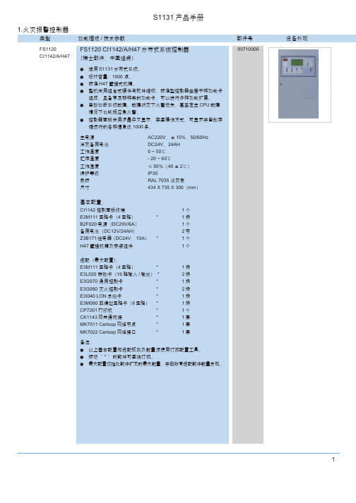
选配(最大配置):
BCH1935 双琴台
(1)
1个
Rack/WG 立柜(带玻璃门)
(1)
1个
ZA2711B/24 火警通讯盘
1个
ZA2711B/40 火警通讯盘
*
1个
ZA5711A 总线制火警通讯盘
*
1个
ZA2715/10 电话主机
*
1个
ZA2715/30 电话主机
*
1个
ZA2721A 广播录放盘
*
设备外观
3
S1131 产品手册
类型
功能描述 / 技术参数
部件号
FS1120
FS1120 CC114x-/A/Rack 分布式系统控制器 (上柜式)
CC114x-/A/Rack (瑞士部件,中国组装)
● 适用 S1131 分布式系统。 ● 设计容量:2000 点。 ● 标准 H67 安装底板组件,可安装于 BCH1950 双琴台或 Rack/WG
AC220V,± 15%,50/60Hz DC24V,38AH 0 ~ 50℃ - 20 ~ 60℃ ≤ 95%(40 ± 2℃) IP30 RAL 7035 淡灰色 434 X 1130 X 300 (mm)
基本配置:
CC1142 主 CPU 控制单元
1个
CT1142 控制面板终端
1个
E3M111 回路卡(4 回路) B2F020 电源(DC29V/6A)
基本配置:
BCH1950 双琴台
(1)
1个
CC1142 主 CPU 控制单元
1个
E3M111 回路卡(4 回路)
*
1块
B2F020 电源(DC29V/6A)
海格模数化电气产品

16
熔断器座
17
插拔式电涌保护装置
18
插拔式电涌保护装置更换备件(芯体)
19
固定式电涌保护装置
20
绝缘汇流排
21
6
6kA“相线+中性线”微型断路器C曲线 (1位)
说明: “相线+中性线”微型断路器 在保护性动作脱扣时,同时断 开相线和中性线,具有隔离功 能。 用于住宅配电系统,避免中性 线故障时带电。
说明 : “相线+中性线”微型断路器 在保护性动作脱扣时,同时断 开相线和中性线,具有隔离功 能。 用于住宅配电系统,避免中性 线故障时带电。
技术参数 : 符合IEC60898,GB10963-1999 标准 分断能力:6000A C型脱扣特性:5-10In 额定电压:230V AC 额定电流:6-63A 电气寿命:20,000次 环境温度:-25˚C至60˚C
接线 : 硬线25mm2 软线16mm2
特点 : 左右两边均开窗。 可与漏电附加器及电器附件组 合使用。
设计分类 MN240K
额定电流 (A)
6 10 16 20 25 32 40 50 63
宽度/位 17.5mm
2 2 2 2 2 2 2 2 2
◆技术资料见31页
包装 数量
产品 编号
6
MN206K
(A)
17.5mm
包装 数量
产品编号
C曲线
D曲线
单极微型断路器 双极微型断路器 三极微型断路器 四极微型断路器
0.5
1
12
MC100P MD100P
1
1
12
MC101P MD101P
2
1
12
MC102P MD102P
Moxa AWK-1151C 系列工業級無線用戶端說明说明书

AWK-1151C系列工業級IEEE802.11a/b/g/n/ac無線用戶端特色與優點•IEEE802.11a/b/g/n/ac Wave2無線用戶端•可選擇的雙頻Wi-Fi,資料傳輸速率高達867Mbps•最新的WPA3加密增強無線網路安全性•具有可配置國碼或區碼的通用(UN)型號,部署更彈性•透過網路位址轉譯(NAT)輕鬆設定網路•毫秒等級的用戶端Turbo Roaming漫遊1•內建2.4GHz和5GHz具有通濾波器,無線連線更可靠•-40至75°C寬操作溫度範圍(-T型號)•整合式天線隔離認證簡介AWK-1151C系列工業無線用戶端透過IEEE802.11ac技術滿足日益增長的加速資料傳輸需求,資料傳輸速率高達867Mbps。
在操作溫度、電源輸入電壓、突波、ESD和振動方面,AWK-1151C符合工業標準及規定。
具有DIN軌道或選配壁掛式安裝的輕巧外型可輕鬆安裝到工業機器或控制機櫃,提供可靠的無線連線。
AWK-1151C可以在2.4或5GHz頻段上操作,並相容現有的802.11a/b/g/n部署。
進階802.11ac工業無線解決方案•802.11a/b/g/n/ac相容的用戶端,提供彈性的部署方式•DFS頻道支援提供更廣泛的5GHz頻道選擇,避免現有無線基礎設施的干擾先進無線技術•基於用戶端的Turbo Roaming快速漫遊,達到無縫漫遊的目的。
2在AP間的漫遊復原時間<150毫秒(用戶端模式)工業級耐用性•整合式天線隔離設計可防止外部電氣干擾•-40至75°C的寬廣操作溫度型號(-T)可在惡劣環境中提供順暢的無線通訊規格WLAN InterfaceWLAN Standards 2.4GHz:802.11b/g/n with256QAM support5GHz:802.11a/n/ac Wave2with256QAM supportFrequency Band for US(20MHz operating channels)AWK-1151C US Models Only:2.412to2.462GHz(11channels)5.180to5.240GHz(4channels)5.260to5.320GHz(4channels)31.此處所指的Turbo Roaming快速漫遊復原時間是在最佳狀態下,配置無干擾20MHz RF頻道、WPA2-PSK安全性和預設的Turbo Roaming快速漫遊參數,所得到的測試結果平均值。
WJ1141AS1015VDC5.0中文资料
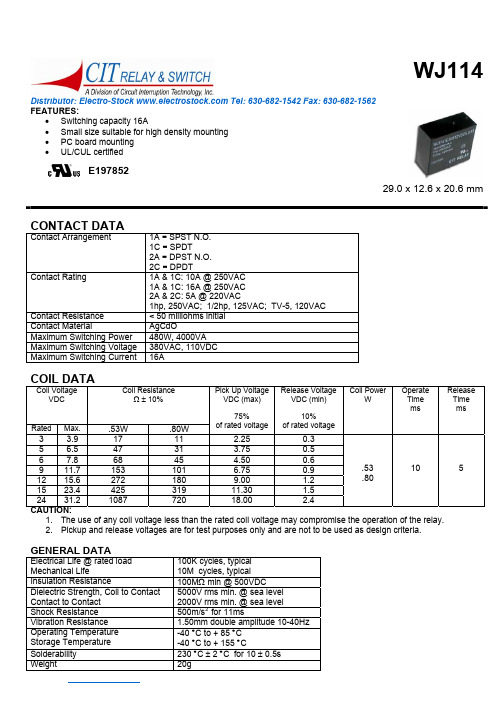
Distributor: Electro-Stock Tel: 630-682-1542 Fax: 630-682-1562 FEATURES:• Switching capacity 16A• Small size suitable for high density mounting • PC board mounting • UL/CUL certifiedE19785229.0 x 12.6 x 20.6 mmCONTACT DATAContact Arrangement1A = SPST N.O. 1C = SPDT2A = DPST N.O. 2C = DPDTContact Rating1A & 1C: 10A @ 250VAC 1A & 1C: 16A @ 250VAC 2A & 2C: 5A @ 220VAC1hp, 250VAC; 1/2hp, 125VAC; TV-5, 120VAC Contact Resistance < 50 milliohms initial Contact MaterialAgCdOMaximum Switching Power 480W, 4000VA Maximum Switching Voltage 380VAC, 110VDC Maximum Switching Current 16ACOIL DATACoil VoltageVDCCoil ResistanceΩ ± 10%Rated Max..53W .80WPick Up Voltage VDC (max)75%of rated voltage Release Voltage VDC (min)10%of rated voltageCoil PowerWOperate Time msRelease Time ms3 3.9 17 11 2.25 0.3 5 6.5 47 31 3.750.5 6 7.8 68 45 4.50 0.6 9 11.7 153 101 6.75 0.912 15.6 272 180 9.00 1.215 23.4 425 319 11.30 1.5 24 31.2 1087 720 18.00 2.4.53 .8010 5CAUTION:1. The use of any coil voltage less than the rated coil voltage may compromise the operation of the relay.2. Pickup and release voltages are for test purposes only and are not to be used as design criteria.GENERAL DATAElectrical Life @ rated load Mechanical Life 100K cycles, typical 10M cycles, typical Insulation Resistance 100M Ω min @ 500VDCDielectric Strength, Coil to Contact Contact to Contact 5000V rms min. @ sea level 2000V rms min. @ sea level Shock Resistance 500m/s 2 for 11ms Vibration Resistance 1.50mm double amplitude 10-40Hz Operating Temperature Storage Temperature -40 °C to + 85 °C -40 °C to + 155 °C Solderability 230 °C ± 2 °C for 10 ± 0.5sWeight 20gDistributor: Electro-Stock Tel: 630-682-1542 Fax: 630-682-1562ORDERING INFORMATION1. Series:WJ114WJ1142.Contact Arrangement: 1A = SPST N.O.1C = SPDT2A = DPST N.O. 2C = DPDT1C 3. Sealing Options:S = SealedS 4. Contact Rating:5 = 5A (2A & 2C contact arrangement only) 10 = 10A (1A & 1C contact arrangement only) 16 = 16A (1A & 1C contact arrangement only) 16 5. Coil Voltage:3VDC **Only available with 1 Pole Versions 5VDC **Only available with 1 Pole Versions 6VDC 9VDC 12VDC 15VDC 24VDC12VDC 6. Terminal Spacing (L Dimension): 3.5 = 3.5mm 5.0 = 5.0mm 3.5 7. Coil Power: .53 = .53W .80 = .80W.80DIMENSIONS (Units = mm)SCHEMATICS & PC LAYOUTS (BOTTOM VIEWS)1A (10A)1C (10A)1A (16A) 1C (16A) 2A2C。
WJF-31A-03D技术及使用说明书
目次1使用技术说明书 (1)2技术数据 (1)2.1额定数据 (1)2.2主要技术性能 (2)2.3绝缘性能 (2)2.4电磁兼容性能 (3)2.5机械性能 (3)2.6机械结构 (3)2.7重量 (3)3保护原理 (4)3.1低压减载保护 (4)3.2低频减载保护 (6)3.3PT断线 (8)3.4故障报文及故障录波 (8)4监控功能 (12)4.1监视功能 (12)4.2控制功能 (12)4.3通讯功能 (12)4.4打印功能 (12)4.5GPS校时功能 (12)5装置跳线说明 (13)6定值及整定说明 (14)6.1保护定值整定说明 (14)6.2出厂设置整定说明 (16)7装置介绍 (18)7.1键盘简介 (18)7.2后端子布置简介 (18)8菜单操作指南 (20)8.1基本操作 (20)8.2功能简介 (22)8.3主要功能操作说明 (22)9用户调试大纲 (33)9.1试验仪器 (33)9.2试验注意事项 (33)9.3保护装置的准备....................................................错误!未定义书签。
9.4开关量输入检查 (33)9.5交流回路校验 (33)9.6开出接点检查 (35)10运行及维护 (36)10.1重要注意事项 (36)10.2简单故障维护指南 (36)11供应成套性 (37)12订货须知 (37)附录A (38)A.1结构图 (38)A.2开出分组整定序号与开出继电器对应关系表 (39)A.3分组配置参数的默认值 (39)A.4默认值表 (42)A.4.1保护整定值默认配置表 (42)A.4.2其他参数默认值表 (44)1使用技术说明书WJF-31A/03D微机低频低压减载装置(以下简称装置)可实现三段母线最多28回线路的低频、低压自动减载功能,装置具有28路独立的出口,每个独立的出口具有最多三付常开接点,各个保护可分别整定不同出口。
直流电源自动控制显示器(内建 MODBUS) 产品说明书

150S直流电源自动控制显示器(内建MODBUS)说明书目錄安全注意事項 (3)特點介紹 (3)第一章前/後面板,規格介紹 (4)1-1 前面板 (4)1-2 後面板 (4)1-3 按鍵說明 (5)1-4 技術參數 (5)1-5 查看程式版號 (6)第二章一般常用功能說明 (7)2-1 各項設定操作程式 (7)2-2 功能設定 (9)2-3 錯誤訊息(於一般校正時顯示) (12)第三章校正 (13)3-1 荷重元安裝 (13)3-2 校正參數設定及校正流程 (14)3-3 MODBUS 校正 (16)3-4 規格校正 (17)3-5 一般校正 (19)3-6 線性校正 (20)3-7 數位校正 (22)第四章重量比較程式 (23)4-1 重量比較程式之設定說明 (23)4-2 重量檢測之參數設定 (26)4-3 計量信號輸出條件 (29)4-4 一般投入計量流程圖(SQ-01=1) (30)4-5 一般排出計量流程圖(SQ-01=2) (31)4-6 Hi,OK,Lo輸出時機流程圖 (32)4-7 內建程式投入計量流程圖(SQ-01=4) (33)4-8 內建程式排出計量流程圖(SQ-01=5) (34)4-9 保持模式(SQ-01 = 6) (35)4-9-1 保持模式流程圖(SQ-01=6 SQ-16=0或2或4) (36)4-9-2 保持模式之Hi,OK,Lo重量比較 (37)4-10 自動累加/傳送 (37)第五章介面 (38)5-1 串行輸出/入介面(內建, OP-01) (38)5-2 BCD並列輸出介面(OP-02) (46)5-3 類比電流/電壓輸出介面(OP-03) (48)5-4 外部信號輸出/輸入介面(OP-04,OP-05) (51)第六章維護 (56)6-1 所有參數恢復為出廠設定值 (56)6-2 功能參數維護 (56)6-2-1 功能設定參數恢復為出廠設定值 (56)6-2-2 清除零點補償值及扣重值 (56)6-2-3 清除計量設定值 (57)6-2-4 顯示零點電壓值(mV/V) (57)6-2-5 顯示跨距電壓值(mV/V) (57)6-3 測試模式 (58)6-3-1 7段顯示器及各指示符號測試 (59)6-3-2 按鍵及校正開關測試 (59)6-3-3 A/D內部值顯示測試 (59)6-3-4 內建RS-232串列輸出入測試 (59)6-3-5 EEPROM記憶體測試 (59)6-3-6 Option介面卡測試 (59)附錄一七節碼字樣說明 (61)附錄二功能明細表 (62)附錄三MODBUS Data Address Table I (71)附錄四Modbus Data Address Table II (72)附錄五MODBUS輸入與輸出格式說明 (73)第一章前/後面板,規格介紹∙6位數,紅色7段顯示器,字高0.63∙可作毛重/淨重/累計重量/累計次數之切換顯示指示符號“ ◄ ”ZERO ◄: 重量置零指示MD ◄: 不穩定指示GROSS ◄: 毛重指示NET ◄: 淨重指示使用者可利用FNC- 06 ~ FNC- 09依需求設定各“ ◄ ”符號之指示意義,並從隨機所附之貼紙中選用適合之小貼紙,貼於“ ◄ ”符號左邊機殼上,方便操作時判讀其意義。
CFV106说明书
CFV106说明书
CFV106系列变频器采用模块化的功能设计理念,实用的PI、简易PLC、多路可编程继电器输出、多路灵活的模拟量输入输出、掉电参数存储、双行LED/LCD显示,完善的用户密码保护,可专为行业需求提供解决方案。
本手册适用于V6116或以上程序版本,它将为您提供CFV106系列变频器的安装、接线、功能参数、故障处理和维护以及配件选型等相关细则及注意事项。
为正确使用CFV106系列变频器,充分发挥产品的卓越性能并确保使用者和设备的安全,在使用前请您务必仔细阅读本手册。
使用后请您妥善保管,以备今后对变频器进行检修维护。
1、产品在运输过程中是否有损坏变形,零部件是否有损坏、脱落现象。
2、本机右侧面铭牌所标注的额定值是否与您的订货要求一致。
3、装箱清单所列物品是否齐全。
如有疑问或者产品出现损坏,请及时与本公司或您的供货商联系解决。
DAM0800-GPRS 产品说明书

DAM0800-GPRS继电器控制卡说明书V1.0北京聚英翱翔电子有限责任公司2016年01月目录一、产品说明 (1)二、产品特点 (1)三、产品功能 (1)四、产品选型 (1)五、主要参数 (1)六、通讯架构说明 (2)七、使用说明 (2)八、硬件说明 (3)1、接口说明 (3)2、继电器接线说明 (3)九、设备唯一ID号 (3)1、扫描二维码获取 (4)2、发送短信查询指令获取 (4)十、短信配置说明 (4)1、查询指令 (4)2、网络配置及查询 (5)3、软件生成指令 (6)十一、平台软件说明 (6)十二、软件下载 (7)1、网页版平台入口 (7)2、手机版软件下载 (7)十三、平台操作说明 (7)1、登陆 (7)2、添加设备 (8)3、实时监控 (10)4、删除设备 (14)十四、开发资料说明 (14)1、Modbus寄存器说明 (14)2、相关指令 (16)3、指令详解 (16)十五、技术支持联系方式 (18)一、产品说明DAM0800-GPRS设备是我公司DAM系列设备中GPRS版本的一种,设备基于移动和联通的GPRS网络来进行通讯,使用我司配套的云平台软件可实现远程控制设备功能,每个设备具有唯一ID号方便用户进行二次开发使用。
二、产品特点●供电电压DC7-30V;●继电器输出触点隔离;●使用GPRS通讯,SIM卡支持移动、联通,暂不支持电信;●通信波特率:2400,4800,9600,19200,38400●通信协议:支持标准modbus协议;三、产品功能●八路继电器控制;●可实现远距离操控;●具有闪开、闪断功能,可以在指令里边带参数、操作继电器开一段时间自动关闭。
四、产品选型型号modbus RS232RS485USB GSM继电器DAM0800-GPRS●●8五、主要参数参数说明触点容量10A/30VDC10A/250VAC耐久性10万次通讯接口GSM网络(移动、联通)额定电压DC7-30V电源指示1路红色LED指示(不通信时常亮,通信时闪烁)输出指示8路红色LED指示温度范围工业级,-40℃~85℃尺寸145*94*41mm重量330g默认通讯格式9600,n,8,1波特率2400,4800,9600,19200,38400软件支持配套配置软件、app控制软件,平台软件;支持各家组态软件;支持Labviewd等六、通讯架构说明设备使用基于移动或联通的GSM网络进行远程通讯,设备上插入移动或联通SIM卡即可,支持流量卡。
西门子TIC106系列硅控直流接地器说明书
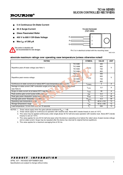
VAA = 12 V Initiating IT = 10 mA VAA = 12 V Initiating IT = 10 mA
RGK = 1 kΩ RGK = 1 kΩ
TC = - 40°C
8 mA
5
Peak on-state
VT
voltage
IT = 5 A
(See Note 6)
1.7
V
OBSOLETE dv/dt
Figure 4.
3
TIC106 SERIES SILICON CONTROLLED RECTIFIERS
VGT - Gate Trigger Voltage - V IH - Holding Current - mA
TYPICAL CHARACTERISTICS
GATE TRIGGER VOLTAGE vs
vs
ON-STATE CURRENT
100
TI20AB
TJ = 110°C
PA - Anode Power Dissipated - W
4
Φ = 180º
3
10
2
1 0
30
100
OBSOLETE 0°
180°
Φ
Conduction
Angle
40 50 60 70 80 90 100 110 TC - Case Temperature - °C
Figure 1.
SURGE ON-STATE CURRENT vs
CYCLES OF CURRENT DURATION
TI20AC
TC ≤ 80 °C No Prior Device Conduction
1
1
10
JWSL系列壁挂型温湿度变送器使用说明书V
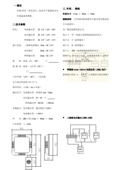
Power-+43+21A-VV-+BDC12/24一.概述传感,变送一体化设计, 适适用于暖通级室内环境温湿度测量。
二.技术参数供电: 电流输出型 DC 24V (22V ~26V ) 电压输出型 DC 24V (12V ~24V ) 网络输出型 DC 24V (12V ~24V ) 最大电流: 二线制电流输出 40mA (DC 24V ) 电压输出 20mA (DC 24V ) 网络输出型 20mA (DC 24V量 程: 温度: 0℃~50℃ □ 准 确 度: 温度: ±0.5℃(25℃)□ 工作环境: -10℃~60℃; (非结露) 长久稳定性温度≤0.1℃/y 响应时间: ≤15s (1m/s 风速)输出信号: 电流输出型: 两线制4mA ~20mA电压输出型: 0V ~5V □ 网络输出型: RS485 □RS232 负载能力: 电压输出型: 输出阻抗≤250Ω 电流输出型: ≤500Ω外 壳: ABS 白色84mm × 90mm × 35mm 产品重量: ≤ 120g三.外形、 接线外形尺寸: 84mm × 90mm × 35mm接线说明: (任何错误接线都有可能对变送器造成 不可逆损坏) 出厂测试线颜色默认为端子4: V+(电源正或两线制温度供电正) 端子3: T (温度输出) 端子2: H (湿度输出)端子1: GND (地或两线制湿度供电正) 图例中A, B 为显示仪表, 实施器或采集卡,A 路对应湿度输出, B 路对应温度输出。
● 两线制4mA ~20mA 电流远传(JWSL-2AT ) 能够独立供电(4、 3和2、 1两路信号相互隔离)● 三线制电压输出(JWSL-2VB)网络型: (JWSL-2W1/W2) 端子4: V+ (电源正)端子3: RT+ (RS232接收RX 或485 A+) 端子2: RT- (RS232发送TX 或485 B-) 端子1: GND (电源地)注:通讯协议详见附录和产品配套光盘,并提供通讯测试软件四.安装安装步骤:1、 变送器后面葫芦孔挂装;2、 变送器后面螺丝固定墙面;3、 用电缆线连接到端子上, 然后接采集设备; 安装位置:1、 变送器应尽可能垂直放置, 安装时, 确保传感器在变送器下方(变送器上字体为正方向)。
- 1、下载文档前请自行甄别文档内容的完整性,平台不提供额外的编辑、内容补充、找答案等附加服务。
- 2、"仅部分预览"的文档,不可在线预览部分如存在完整性等问题,可反馈申请退款(可完整预览的文档不适用该条件!)。
- 3、如文档侵犯您的权益,请联系客服反馈,我们会尽快为您处理(人工客服工作时间:9:00-18:30)。
Distributor: Electro-Stock Tel: 630-682-1542 Fax: 630-682-1562 FEATURES:
• Switching capacity 16A
• Small size suitable for high density mounting • PC board mounting • UL/CUL certified
E197852
29.0 x 12.6 x 20.6 mm
CONTACT DATA
Contact Arrangement
1A = SPST N.O. 1C = SPDT
2A = DPST N.O. 2C = DPDT
Contact Rating
1A & 1C: 10A @ 250VAC 1A & 1C: 16A @ 250VAC 2A & 2C: 5A @ 220VAC
1hp, 250VAC; 1/2hp, 125VAC; TV-5, 120VAC Contact Resistance < 50 milliohms initial Contact Material
AgCdO
Maximum Switching Power 480W, 4000VA Maximum Switching Voltage 380VAC, 110VDC Maximum Switching Current 16A
COIL DATA
Coil Voltage
VDC
Coil Resistance
Ω ± 10%
Rated Max.
.53W .80W
Pick Up Voltage VDC (max)
75%
of rated voltage Release Voltage VDC (min)
10%
of rated voltage
Coil Power
W
Operate Time ms
Release Time ms
3 3.9 17 11 2.25 0.3 5 6.5 47 31 3.75
0.5 6 7.8 68 45 4.50 0.6 9 11.7 153 101 6.75 0.9
12 15.6 272 180 9.00 1.2
15 23.4 425 319 11.30 1.5 24 31.2 1087 720 18.00 2.4
.53 .80
10 5
CAUTION:
1. The use of any coil voltage less than the rated coil voltage may compromise the operation of the relay.
2. Pickup and release voltages are for test purposes only and are not to be used as design criteria.
GENERAL DATA
Electrical Life @ rated load Mechanical Life 100K cycles, typical 10M cycles, typical Insulation Resistance 100M Ω min @ 500VDC
Dielectric Strength, Coil to Contact Contact to Contact 5000V rms min. @ sea level 2000V rms min. @ sea level Shock Resistance 500m/s 2 for 11ms Vibration Resistance 1.50mm double amplitude 10-40Hz Operating Temperature Storage Temperature -40 °C to + 85 °C -40 °C to + 155 °C Solderability 230 °C ± 2 °C for 10 ± 0.5s
Weight 20g
Distributor: Electro-Stock Tel: 630-682-1542 Fax: 630-682-1562
ORDERING INFORMATION
1. Series:
WJ114
WJ114
2.Contact Arrangement: 1A = SPST N.O.
1C = SPDT
2A = DPST N.O. 2C = DPDT
1C 3. Sealing Options:
S = Sealed
S 4. Contact Rating:
5 = 5A (2A & 2C contact arrangement only) 10 = 10A (1A & 1C contact arrangement only) 1
6 = 16A (1A & 1C contact arrangement only) 16 5. Coil Voltage:
3VDC **Only available with 1 Pole Versions 5VDC **Only available with 1 Pole Versions 6VDC 9VDC 12VDC 15VDC 24VDC
12VDC 6. Terminal Spacing (L Dimension): 3.5 = 3.5mm 5.0 = 5.0mm 3.5 7. Coil Power: .53 = .53W .80 = .80W
.80
DIMENSIONS (Units = mm)
SCHEMATICS & PC LAYOUTS (BOTTOM VIEWS)
1A (10A)
1C (10A)
1A (16A) 1C (16A) 2A
2C。
