8203中文资料
固化剂(MSDS)

高热有燃烧危险。
眼睛接触
立即翻开眼睑,用流动的清水或生理盐水冲洗,至少15分钟,就医。
皮肤接触
立即脱去污染的衣着,用肥皂水及清水彻底冲洗皮肤,至少15分钟,就医。
吸入
迅速脱离现场至空气新鲜处。严重时进行人工呼吸。就医。
食入
立及催吐,立即就医。
危险特性
高热能引起燃烧
有害燃烧产物
一氧化碳(CO)。
辛醇/水分配系数的对数值:无标准
溶解性:微溶于石油醚;易溶于苯、丙酮、四氯化碳、三氯甲烷、乙醉等。
主要用途
用于电器行业,环氧树脂固化剂。
稳定性
常温下稳定。
避免接触的条件
避免明火、火星、高热。
聚合危害
不能发生。
急性毒性
LD50:小白鼠0.222g/kg,大白鼠0.255g/kg(体内注射);LD50:小白鼠1.707g/kg,大白鼠2.102g/kg(口服)
PH值:81-85
熔点(℃):无标准
沸点(100mmHg,℃):210蒸气相对密度(空气=1)
相对密度:(水=1):1.70
蒸气相对密度(空气=1)
凝固点(℃):≤-15
闪点(℃):≥130
溶解性:难溶。
临界压力/MPA:无标准
临界温度:无标准
燃烧热/(KJ/MOL)
爆炸上限(%):无
爆炸下限(%):无
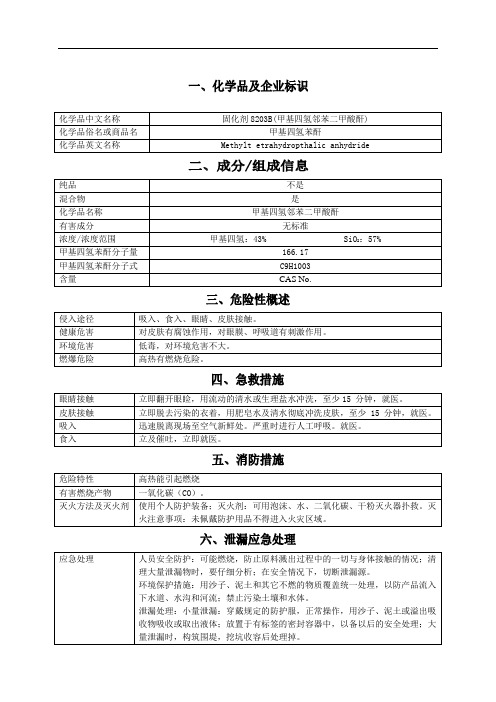
化学品中文名称
固化剂8203B(甲基四氢邻苯二甲酸酐)
化学品俗名或商品名
甲基四氢苯酐
化学品英文名称
Methylt etrahydropthalic anhydride
企业名称
广急信息
电话:0086-20-
技术说明书编码
RN8203用户手册_v1.0

Renergy单相多功能专用计量芯片RN8203深圳市锐能微科技有限公司page 1 of 22 Rev 1.0RN8203 用户手册Data: 2009-5-13Rev: 1.0目录1 芯片介绍 (3)1.1芯片特性 (3)1.2功能简介 (3)1.3功能框图 (4)1.4管脚说明 (4)1.5典型应用 (6)2 系统功能 (7)2.1 电源监测 (7)2.2 系统复位 (7)2.3 模数转换 (7)2.4 有功功率 (8)2.5 有效值 (8)2.6 能量计算 (9)2.7 频率测量 (10)2.8过零检测 (10)2.9 事件标志 (11)2.10寄存器 (11)3 校表方法 (17)3.1 校表流程和参数计算 (17)3.2 举例 (20)4 RSIO接口 (20)5 电气特性 (21)6 芯片封装 (22)1 芯片介绍1.1芯片特性9计量有功电能误差在1500:1动态范围内<0.1%,支持IEC62053-22:2003标准要求提供电流和电压有效值测量,在400:1动态范围内,有效值误差<0.5%潜动阈值可调提供反相功率指示提供电压通道频率测量提供电压通道过零检测9软件校表电表常数(HFConst)可调提供增益和相位校正提供有功和有效值offset校正提供小信号校表加速功能提供配置参数自动校验功能9提供单线通讯RSIO接口9具有电源监控功能9单+5V电源供电,功耗典型值为16.5 mW9内置2.5V±3% Reference,温度系数典型值25ppm/℃9采用SSOP24无铅封装9PIN to PIN 兼容ADE77551.2功能简介RN8203是一颗带单线通信接口的高精度单相电能计量芯片,适用于软件校表的单相液晶表应用。
RN8203集成了两路sigma-delta ADC、参考电压以及数字信号处理等电路,能够测量有功功率、有功能量、电流通道有效值、电压通道有效值、电压线频率、电压过零等。
SPHE8203R - Des Guide

CARD Reader TVUSB 2.0CVBS/YUV/SCART(SD/MMC/MS)SPI FlashGameDVD Loader8203RICHDMI5.1CH AudioVFD/IRSPHE8203RFigure 2-2 計算特性阻抗SPHE8203RFigure 2-4 HDMI differential trace layoutSPHE8203RFigure 2-6 USB 2.0 differential trace layoutSPHE8203RR3Figure 2-8 建議系統的 Reset Circuit SPHE8203RFigure 2-10 A+5V Power(2) M+5V Power提供給 motor driver 的 power,由於為主要耗電元件,因此穩壓電容非常的重要,務必在進driver 前配置大型電解電容。
並注意此 power 分支不宜和其他 5VFigure 2-11 M+5V PowerClose to 8203RFigure 2-13 PHURF layoutFigure 2-14 高頻信號參考訊號走線計有 Vref1、Vref2等兩種參考訊號,Vref1需接Bulk and bypass 電容以保證訊號穩定性而針對VREF2,目前SPHE8203R是以一新架構來產生出所需VREF2訊號,所以在線路上請依照藍色框線內的設定值設置,其中,圖2-15中的470 ohm電阻需盡量靠近SPHE8203R擺放。
Figure 2-15 參考訊號Figure 2-16 Audio OP PowerFigure 2-18 Crystal layoutSPHE8203RFigure 2-19 Load control signals 2.13 PCB LayoutFigure 2-20 Power trace layoutFigure 2-21 Power trace with I/O connector(3) 要注意所有信號線不可有跨plane (power and ground plane) 的情形發生。
中国政法大学学院路校区号码

学院路校区管委会办公室办公室——————8032——————8033——————8034 校友办——————8022 会议室——————8035——————8036 收发室——————8037组织部办公室—————8573统战部办公室—————8461 民主党派—————8038纪委、监察处办公室—————8093宣传部办公室——————8540 广播台——————8039 LED屏播放室——8577离退休干部管理处处长办——————8041 分党委——————8098 副处长办—————8042 离休办——————8043 退休办——————8045 活动室——————8044 老年人权益保障研究中心—————8046 公关委——————8097科研处办公室——————8051 传真——————8052人事处办公室——————8550研究生院院长办——————8056 副院长办—————8057—————8058 办公室——————8059——————8060 博士后办—————8063培养办——————8066——————8067——————8076学位办——————8068——————8390招生办——————8070——————8071招生传真—————8074招生机要—————8073教室调度—————8078研究生法学编辑部—8527发展规划与学科建设处处长办—————8053副处长办—————8062—————8471综合科—————8061传真——————8054开放教育管理办公室主任办——————8161副主任——————8542办公室——————8454——————8064——————8065会议室——————8554国际合作与交流处长办——————8080副处长——————8365综合科——————8082——————8083交流科——————8085——————8086专家科——————8049传真——————8081——————8084学生工作部就业中心办————8090研究生工作办———8091心理健康咨询———8389综合办—————8511学生工作办————8510就业咨询————8512财务处处长办——————8095——————8547结算中心—————8096会计结算二科———8578审计跟踪审计—————8152—————8509保卫处处长办——————8100办公室——————8101治安二科—————8102综合二科—————8103总值班室—————8104—————8110监控室—————8543东门——————8105北门——————8106南门——————8107保安队——————8108政法家委会————8109塔楼家委会————8111明光楼家委会———811218#楼传达室———834215#楼传达室———8314人口普查办———8576资产管理处房产科——————8116传真——————8117后勤工作委员会办公室办公室——————8118基建处处长办——————8119办公室——————8120——————8546拆迁建设办公室办公室——————8371团委办公室——————8137研究生会—————8002法律援助中心———8411研究生工作办——8253工会办公室——————8138校医院保健科——————8139急诊室——————8140内科(一)————8350内科(二)————8351护士办——————8352药房——————8353口腔科——————8354挂号室——————8355化验室——————8356饮食服务中心主任办——————8142办公室——————8143值班室/门岗————8144法学餐厅—————8145回民餐厅—————8146正文园商店————8172————8173运输服务中心办公室——————8150——————8419休息室——————8151学生公寓管理服务中心办公室——————8157——————81582#公寓门卫————8162新1#公寓门卫———8160家政服务部———8161培训公寓办公室——8153培训公寓接待室——8337培训公寓值班———8437物业管理服务中心副主任办—————8163办公室——————8164——————8174经理室——————8155保洁部——————8156绿化环保部————8154预算室——————8169房产维修—————8165水暖维修—————8166热力供应—————8167电卡充值—————8168 电器维修—————8170 配电室—————8171 新1#公寓浴池——8364 新1#保洁值班——8528电信服务中心主任办——————8008 机线维护部————8006 电信营业厅————8503司法考试学院院长办——————8122——————8123 网络部——————8375 教学研究部————8127——————8128——————8126——————8133 教学研究部————8129——————8376——————8377——————8131法学院办公室——————8178——————8177 研究生工作办———8175——————8176——————8381——————8382 就业办——————8395 培训部——————8179——————8180——————8181——————8182——————8183——————8185民商经济法学院办公室——————8186——————8187——————8188——————8366 研究生工作办———8189——————9357 博士点——————8190——————8191 江平办——————8192 网站——————8404国际法学院院长办——————8548办公室——————8195——————8196博导办公室————8197研究生工作办———8198——————8199——————8336——————8383外事办——————8384辅导员办—————8360研究生教研办———8361在职教育培训办——8200出国留学培训办——8558——————8585刑事司法学院院长办——————8209研究生工作办———8201——————8202——————8372传真——————8203侦查学实验室———8204政治与公共管理学院院长办——————8205——————8378MPA教育办———8206————8380研究生工作办———8207——————8519博导办——————8518国际化与国际问题—8000———8497政治文化与政治文明研究所——————8520培训部——————8208商学院办公室——————8210——————8211研究生办—————8212—————8214培训部——————8213商学院(一)———8448商学院(二)———8449研究所—————8534MBA教育办———8536———8537MBA综合服务办———8587人文学院李德顺办—————8391办公室——————8216研究生办—————8217外国语学院办公室——————8220研究生外语教务办——————8221——————8222研究生外语教研室——————8223无线发射台————8224研工办——————8387——————8397英语语言文学研究所——————8541继续教育学院副院长——————8472——————8125分党委——————8473财务室——————8475院务办——————8476——————8477——————8478——————8479律师学院—————8484—————8487招生与学籍办———8489—————8490函授站管理办———8491教务考务办————8493—————8494司法职业教育中心—————8481海外留学教育中心—————8480—————8482—————8486政府与企业管理教育中心—————8225对外拓展部————8483研发中心—————8438—————8226—————8485成人学历教育中心————8227夜大学——————8228——————8229——————8495——————8496—————8492研究室——————8230教材部——————8231高级政法管理干部进修中心办公室—————8464—————8469副主任办—————8465常务副主任————8467教学部—————8468会议室—————8470新闻与传播学院办公室——————8115教务办——————8474文化产业导报编辑室—————8580—————8581国际教育学院院长办——————8234院长传真—————8235副院长办—————8236——————8238院办——————8233——————8338院办传真—————8339国际合作部————8237港澳台侨办————8239——————8240外国留学生————8241汉语言专业————8340暑期学校办————8341法硕学院院办/党总支———8517————8552教学科研办————8075————8553中欧法学院办公室—————8092社会学院院长办——————8024 研工办——————8014 心理学教研室———8531 社会学教研室———8532马克思主义学院院长办——————8218 研究生办—————8219国际儒学院办公室——————8001中德法学院办公室——————8242——————8243 图书馆——————8244中美法学院办公室——————8246——————8247 传真——————8245卡特政府学院办公室——————8385——————8386体育教学部办公室——————8250新1#公寓体育馆办公室——————8048 新1#公寓体育馆门卫——————8446科学技术教学部办公室——————8252比较法学研究中心所长办——————8256 办公室——————8257 编辑部——————8258 法学文挡—————8248 教学科研办————8549诉讼法学研究院主任办——————8260名誉主任—————8261顾问室——————8262副主任室—————8263办公室——————8270——————8370——————8388刑诉法学研究室——8264民诉法学研究室——8265行政诉讼研究室——8266证据法学研究室——8267编辑室——————8268图书资料—————8269电子阅览—————8259中文资料室————8394法律史学研究中心主任办——————8271——————8374名誉主任—————8373副主任办—————8272办公室——————8273——————8274破产法与企业重组研究中心办公室——————8278欧盟法研究中心办公室——————8358法学教育研究与评估中心主任办——————8159副主任办—————8149办公室——————8079传真——————8047评估所——————8099研究所——————8255刑事法律研究中心陈光中办—————8379中国法律信息中心主任办——————8113副主任办—————8114—————8582顾问室——————8193办公室——————8147法律信息部————8134监控室——————8194网络机房—————8533法制政府研究院主任室——————8215办公室——————8232——————8003研究室(一)———8040研究室(二)———8303《行政法学》编辑部——————8184证据科学研究院副院长——————8028办公室——————8029教学培训部————8031编辑部——————8121编辑部办公室———8141证据法研究所———8251长江学者艾伦办公室—————8249对外培训部————8431————8432法律古籍整理研究所办公室——————8275——————8463人权与人道主义研究所办公室——————8276——————8277——————8428法和经济研究所办公室——————8077宪政研究所办公室——————8346全国专利保护重点联系基地办公室—————8148《政法论坛》编辑部主编室——————8280办公室——————8281传真——————8279学报办公室——————8005——————8444中关村法大科技园办公室——————8009——————8557传真——————8007出版社社长办——————8282副社长办—————8283总编室——————8284——————8285——————8286——————8287策划编辑室————8288综合编辑部————8289照排室——————8290校对室——————8291文字编辑室————8292美编室——————8293版权部——————8583出版部——————8294教材编辑室————8295实用读物编辑室——8524财务室——————8296社长办公室————8297——————8298前台——————8299读者服务部————8300——————8301网络室——————8302发行部——————8325——————8326储运部——————8335分工会——————8004资料室——————8575图书馆馆长办——————8304副馆长办—————8305办公室——————8306会计室——————8307文献资源—————8308——————8309——————8555电子阅览室————8310信息咨询部————8311现刊阅览室————8312 过刊阅览室————8313 系统部——————8315 外文阅览室————8316 文史书库—————8317 法律书库—————8318 中文阅览室————8319 传达室——————8320 古籍库——————8321信息化建设办公室(现代教育技术中心)网络部——————8451 卡务部——————8452 制作部——————8322 教学服务部————8324其它18#楼电梯值班——8348 15#楼电梯值班——8349 13#楼电梯————8343————8254 15#楼电梯————8344 18#楼电梯————8345。
飞利浦产品用户手册说明书

注册您的产品。
1 重要信息
使用产品之前,请仔细阅读本用户手册,
并妥善保管以供日后参考。
• 警告:请勿在靠近水的地方使用本 产品。
• 本产品在浴室内使用时,使用后拔 下插头,因为即使本产品开关断 开后,接近水仍存在危险。
• 警告:不要在盛水的浴缸、淋浴、 洗脸盆或其他器皿附近使用 本器具。
能与产品电 源电压相符。
压不符。
ϔ৮ 喟下⩢⊓ݖ०䷻ ಸत 喟)1 ䷊Ⴧ⩢ࢸ 喟7_ ䷊Ⴧ䶾⢴ 喟)[ ䷊Ⴧ䓀ߌڒ⢴ 喟8 ⩌ϔᬒ 喟䄤㻮ϔ৮ᳱ ϔౝ 喟͚పᎬ͉͉㣋
⤍⊤㏼≻➦ࡧ下⊓ݖუᏚ⩢கᰶ䭽ڙथ ͚ప⤍⊤ጯ̶▣䩴⥡ⴠጒ͇ࡧ ڕప䶫ߎ☚㏬喟
⤍⊤㏼≻➦ࡧ下⊓ݖუᏚ⩢கᰶ䭽ڙथ ͚ప⤍⊤ጯ̶▣䩴⥡ⴠጒ͇ࡧ ڕప䶫ߎ☚㏬喟
᱙ϔ৮ᵦᢛపᴴ(# (# (# ࣷ(#ݣ䕍
此保用卡在中国适用 用户请保留此卡
产品保用卡
᱙ϔ৮ᵦᢛపᴴ(# (# (# ࣷ(#ݣ䕍
ϔ৮ 喟下⩢⊓ݖ०䷻ ಸत 喟)1 ䷊Ⴧ⩢ࢸ 喟7_ ䷊Ⴧ䶾⢴ 喟)[ ䷊Ⴧ䓀ߌڒ⢴ 喟8 ⩌ϔᬒ 喟䄤㻮ϔ৮ᳱ ϔౝ 喟͚పᎬ͉͉㣋
᱙ϔ৮ᵦᢛపᴴ(# (# (# ࣷ(#ݣ䕍
ϔ৮ 喟下⩢⊓ݖ०䷻ ಸत 喟)1 ䷊Ⴧ⩢ࢸ 喟7_ ䷊Ⴧ䶾⢴ 喟)[ ䷊Ⴧ䓀ߌڒ⢴ 喟8 ⩌ϔᬒ 喟䄤㻮ϔ৮ᳱ ϔౝ 喟͚పᎬ͉͉㣋
未经飞利浦特别推荐的任何附件或 部件。如果使用此类附件或部件, 您的保修将失效。 • 切勿将电源线缠绕在产品上。 • 待产品完全冷却后再存放。 • 使用后请勿拉扯电源线。 拔下产 品插头时,请握紧插头。 • 切勿用湿手操作本产品。 • 产品只能送到飞利浦授权的服务中 心检修。由不合格人员进行修理可 能将用户置于极度危险的境地。
EVQ-P8203M;EVQ-P8403M;EVQ-P8003M;EVQ-P8H03B;EVQ-P4203M;中文规格书,Datasheet资料

(Normal Temp.) 90±30 Soldering Time (s) 40±10
t2
Chip component
Part No. EVQP4 EVQP8
Height 3.5
A
B
W
F 5.5±0.1
+0.2
φ2
5.7±0.1
_0 6.2 +0.4
1.65±0.1 1.25±0.1 0.45±0.1
PWB land pattern for reference
✻ Height from surface of PCB : 1.35 mm Part Numbers EVQP40B3M EVQP42B3M EVQP44B3M EVQP46B3M Operating Force 1.0 N 1.6 N 2.4 N 3.5 N Height 3.5 mm 3.5 mm 3.5 mm 3.5 mm Push Plate Color Natural Natural Natural Natural Operating Life 1000000 cycles 1000000 cycles 500000 cycles 200000 cycles
– ES110 – /
0.3 max. 0.1 max.
Operating Life 1000000 cycles 500000 cycles 200000 cycles
Light Touch Switches/EVQP4/P8
■ Dimensions in mm (not to scale)
_0 6.2 +0.4
Height 3.5 mm 3.5 mm 3.5 mm
Push Plate Color Blue Grey Black
许继电气 WFB-8203 微机电动机保护测控装置 技术及使用说明书

WFB-8203微机电动机保护测控装置技术及使用说明书许继电气股份有限公司XJ ELECTRIC CO.,LTD.许继电气股份有限公司XJ ELECTRIC CO.,LTD 地址:河南省许昌市许继大道1298号/邮编:461000/网址: 订货咨询:************/137****0756询价邮箱:****************目录1概述 (1)1.1应用范围 (1)1.2产品特点 (1)1.3功能配置 (2)2技术参数 (3)2.1基本电气参数 (3)2.2功率消耗 (4)2.3过载能力 (4)2.4触点性能 (4)2.5绝缘性能 (4)2.6冲击电压 (5)2.7机械性能 (5)2.8环境条件 (5)2.9电磁兼容能力 (5)3技术指标 (6)3.1差动保护 (6)3.2磁平衡差动保护 (6)3.3过流保护 (6)3.4反时限过流保护 (6)3.5堵转保护 (6)3.6长启动保护 (6)3.7负序过流保护 (7)3.8过负荷保护 (7)3.9过热保护 (7)3.10零序过流保护 (7)3.11零序过电压 (7)3.12过电压 (7)3.13低电压 (7)3.14低频保护 (7)3.15失步保护 (8)3.16低功率保护 (8)3.17逆功率保护 (8)3.18FC大电流闭锁 (8)3.19低电压启动闭锁功能 (8)3.20电机启动控制功能 (8)3.21非电量 (8)3.22返回值及返回系数 (8)3.23测量元件及精度 (8)3.24通讯及对时 (9)3.25记录容量 (9)4装置功能 (9)4.1比率差动保护 (9)4.2磁平衡差动保护 (12)4.3过流保护 (12)4.4反时限过流保护 (14)4.5电动机长启动保护 (15)4.6堵转保护 (16)4.7负序过流保护 (16)4.8过负荷保护 (17)4.9过热保护 (18)4.10零序过流保护 (19)4.11零序过电压保护 (20)4.12过电压保护 (21)4.13低电压保护 (21)4.14低频保护 (22)4.15失步保护 (23)4.16低功率或逆功率保护 (24)4.17FC回路大电流闭锁 (25)4.18工艺闭锁合闸 (26)4.19电机启动控制功能 (26)4.20非电量保护 (27)4.21断路器状态监测功能 (28)4.22PT异常告警 (30)4.23控制回路异常告警 (30)4.24弹簧未储能告警 (30)4.25跳位异常告警 (30)4.26事故总信号 (30)4.27装置故障告警 (31)4.28遥测、遥信及遥控功能 (31)4.29直流输出 (31)5装置硬件 (31)5.1结构与安装 (32)5.2主要插件 (32)5.3装置跳线说明 (38)5.4装置端子定义 (39)5.5典型接线 (42)6定值 (42)6.1WFB-8203定值单 (43)6.2定值整定说明 (48)7使用说明 (48)7.1液晶显示说明 (49)7.2指示灯说明 (50)7.3调试接口和键盘说明 (50)7.4命令菜单 (51)7.5菜单说明 (51)8装置调试大纲 (63)8.1调试注意事项 (63)8.2程序及硬件检查 (64)8.3开关量输入检查 (64)8.4开出回路检查 (64)8.5模拟量输入检查 (64)8.6整组试验 (64)8.7输出接点检查 (64)8.8装置试验菜单的说明 (65)8.9装置异常信息说明及处理意见 (65)8.10事故分析注意事项 (66)9订货须知 (66)1概述1.1应用范围WFB-8203微机电动机保护测控装置适用于10kV 以下电压等级的中高压电动机的保护测控,装置适用于异步电动机及同步电动机的保护及测控。
伦茨(Lenze)82008210系列变频器中文说明书

782031C N Lenze伦茨橾作手册Global Drive8200/8210系列变频器功率范围0.37…11KW怎样用这些操作指令…对特定的功能,可先参考表中的内容,然后根据索引可看到详细的操作说明为了查阅方便操作指南中用了不同的符号,并在重要的条款中做了加黑处理这个符号给出方便操作信息注意!尽可能避免损坏设备注意!操作时小心人身安全Lenze 1本技术说明用于带有以下名牌的设备8201 E.lx.lx 8203 E.lx.lx 8211 E.Ox.lx 8213 E.Ox.lx 8202 E.lx.lx 8204 E.lx.lx 82l2 E.Ox.lx 82l4 E.0x.lx82l5 E.Ox.lx 82l7 E.Ox.lx 82ll E.lx.2x 82l3 E.lx.2x 82l5 E.lx.2x 82l7 E.lx.2x 82O2E.lx.lx.YOO282l6 E.Ox.lx82l8 E.Ox.lx82l2 E.lx.2x82l4 E.lx.2x82l6 E.lx.2x82l8 E.lx.2x82O2 E.2x.lx.YOO2 装配深度减少的改型变频器类型IP2O封装硬件版本号和索引号软件版本和索引号改型编辑:O3.ll.l994 打印日期 O5.l2.l994 改变软件版本号2x 13.02.199507.08.19952 Lenze目录设计和安装8200/8210系列的特点 (6)1.变频器的数据 (7)1.1通用数据 (7)1.2与型号有关的数据 (8)1.3制造商声明 (9)1.3.1直接应用 (9)2.尺寸和安装 (10)2.1安装 (10)2.2外型尺寸 (11)3.01 (14)3.18200系列变频器的主电路连接 (14)3.28210系列的主电路连接 (15)3.3控制接线 (16)3.4控制输入和输出 (17)3.5并联直流母线运行 (18)3.5.1多台变频器的并联 (18)3.5.2直流电压供电 (18)3.6射频干扰的抑制和屏蔽 (19)4.23 (21)4.1操作面板8201BB (21)4.2操作面板的引出端子的8272BB (22)4.3设定电位器 (23)4.4制动斩波器 (23)4.5主电抗器 (25)4.6熔断器 (26)4.7抑制射频干扰滤波器 (27)4.8电机滤波器 (28)4.9电机电压滤波器 (29)4.10附件 (30)编程:1.开关初始化 (31)2 (32)3.显示 (34)3.1运行状态显示 (34)3.2操作面板8201BB (34)3.3显示值 (36)3.4启动显示 (36)4.基本控制操作 (37)4.1操作编程结构 (37)Lenze 34.2参数代码的设定和改变 (37)4.3操作模式 (40)4.4参数集 (40)5.8200变频器的编程 (41)5.1基本设定 (41)5.1.1最小输出频率f mn (41)5.1.2最大频率设定f_ (41)5.1.3加、减速时间设定 (42)5.1.4V/f 额定频率 (42)5.1.5V/f特性和提升电压设定V_ (43)5.2给定值选择 (44)5.2.1模拟量给定值选择 (44)5.2.2通过LCD操作面板给定 (44)5.2.3寸动频率JOG (45)5.2.4模拟电机电位器 (45)5.3UVWXYZ (46)5.3.1控制器使能(RFR) (46)5.3.2改变旋转方向(CW/CCW) (46)5.3.3快速停止(QSP) (47)5.3.4DC 制动(DC INJ) (47)5.3.5改变参数集(PAR) (47)5.3.6跳闸设定(TRIP) (48)5.3.7端子配置一览 (48)5.3.8继电器输出 (49)5.3.9模拟量输出 (50)5.4扩展设置 (51)5.4.1起动选择/瞬间重起动电路 (51)5.4.2最大电流限制 (52)5.4.3I2.t 监视 (53)5.4.4滑差补偿 (53)5.4.5跳闸复位 (54)5.4.6运行时间表 (54)5.4.7软件版本和变频器型号 (54)5.58200系列代码表 (59)6.8210系列变频器编程 (59)6.1基本设置 (59)6.1.1最小输出频率f;^ (59)6.1.2最大输出频率fj/4 (60)6.1.3加速和减速时间 (61)6.1.4V/f额定频率t (62)6.1.5控制方式 (62)6.1.6提升电压V/i n设定 (62)6.2设定值选择 (62)6.2.1模拟量给定值选择 (63)6.2.2通过操作面板给定 (64)4Lenze6.2.3寸动频率(JOG) (64)6.2.4电机电位器 (64)6.3控制端子功能 (65)6.3.1控制器使能(RFR) (65)6.3.2改变旋转方向(CW/CCW) (66)6.3.3快停(QSP) (66)6.3.4直流制动(DC INJ) (66)6.3.5参数集(TRIP)改变 (67)6.3.6跳闸设定 (68)6.3.7端子配置一览 (69)6.3.8继电器输出 (70)6.3.9模拟量输出 (70)6.4扩展设定 (71)6.4.1起动选择/瞬间重起动 (72)6.4.)最大电流限制 (72)6.4.3电机数据输人 (73)6.4.4I2.t 监控 (73)6.4.5滑差补偿 (74)6.4.6斩波频率 (74)6.4.7跳闸复位 (74)6.4.8运行时间表 (74)6.4.9软件版本和变频器型号 (75)6.4.10运行速度显示 (75)6.58210系列代码表 (76)维护1.监视报警 (81)2.故障报警 (81)2.1主电路连接中错误指示 (81)2.2操作中的故障报警 (81)3.故障确定 (83)3.1电机不转 (83)3.2LED绿灯闪烁 (83)3.3LED红灯闪烁(每0.4秒) (83)3.4LED红灯闪烁(每秒) (83)3.5LED 不亮 (83)3.6电机运行不平稳 (83)3.7电机的电流过大 (84)Lenze 58200/8210系列的特点230V电压等级的8200系列包括4种型号的变频器。
固化剂(MSDS)
迅速脱离现场至空气新鲜处。严重时进行人工呼吸。就医。
食入
立及催吐,立即就医。
危险特性
高热能引起燃烧
有害燃烧产物
一氧化碳(CO)。
灭火方法及灭火剂
使用个人防护装备;灭火剂:可用泡沫、水、二氧化碳、干粉灭火器扑救。灭火注意事项:未佩戴防护用品不得进入火灾区域。
应急处理
人员安全防护:可能燃烧,防止原料溅出过程中的一切与身体接触的情况;清理大量泄漏物时,要仔细分析;在安全情况下,切断泄漏源。
环境保护措施:用沙子、泥土和其它不燃的物质覆盖统一处理,以防产品流入下水道、水沟和河流;禁止污染土壤和水体。
泄漏处理:小量泄漏:穿戴规定的防护服,正常操作,用沙子、泥土或溢出吸收物吸收或取出液体;放置于有标签的密封容器中,以备以后的安全处理;大量泄漏时,构筑围堤,挖坑收容后处理掉。
甲基四氢苯酐分子式
C9H1003
含量
CAS No.
侵入途径
吸入、食入、眼睛、皮肤接触。
健康危害
对皮肤有腐蚀作用,对眼膜、呼吸道有刺激作用。
环境危害
低毒,对环境危害不大。
燃爆危险高热有燃烧危险。Fra bibliotek眼睛接触
立即翻开眼睑,用流动的清水或生理盐水冲洗,至少15分钟,就医。
皮肤接触
立即脱去污染的衣着,用肥皂水及清水彻底冲洗皮肤,至少15分钟,就医。
化学品中文名称
固化剂8203B(甲基四氢邻苯二甲酸酐)
化学品俗名或商品名
甲基四氢苯酐
化学品英文名称
Methylt etrahydropthalic anhydride
纯品
不是
混合物
是
化学品名称
甲基四氢邻苯二甲酸酐
惠而浦 ZDC8203W 全自動滾筒乾衣機 使用手冊说明书

使用手冊簡易入門輕鬆操作中文使用手冊滾筒式乾衣機安全須知請在安裝及使用本設備之前,先詳讀隨附的使用說明,若因安裝及使用不當而導致受傷或損失,製造商恕不負責。
請隨設備妥善保存使用說明,以便日後參考。
一般安全須知請勿擅自變更設備規格。
若要將滾筒式乾衣機置於洗衣機上方,請使用堆疊工具組。
堆疊工具組是隨安裝配件一起提供,可向授權經銷商購買,且僅供使用說明中指定的設備使用,請在安裝前詳閱使用說明(請參閱安裝手冊)。
本設備可獨立安裝或安置於空間合適的廚房流理台下方(請參閱安裝手冊)。
請勿將本設備安裝在可上鎖的門、活動式拉門,或正對設備之該側裝有鉸鏈的門後方,以免設備的門無法完全打開。
請勿將設備安置於地毯上,以免阻塞底部的通風口(視產品機型而定)。
請務必於完成安裝作業後,再連接主電源插頭。
請在完成安裝時,確定主電源插頭與電源插座之間的動線流暢不受阻礙。
請確定安裝乾衣機的空間通風良好,以免使用其他燃料之電器(包括開放火源)產生的熱氣逆流回室內。
設備的廢氣不得與使用瓦斯或其他燃料之設備的廢氣共用排氣管道(若有)。
若電源線損壞,請務必交由製造商、授權維修中心或具備同等資格的專業人員更換。
使用時,請勿置入超過8公斤的負荷上限(請參閱「烘乾程序表」章節說明)。
2請勿將使用工業用化學物品清洗的衣物放入乾衣機內烘乾。
請清除設備周圍累積的棉絮。
請勿在未放置濾板的情況下運轉乾衣機。
請在每一次使用前(後)清潔棉絮濾板。
請勿將未清洗的衣物放入乾衣機內烘乾。
沾有食用油、丙酮、酒精、汽油、煤油、去汙劑、松節油、蠟或除蠟劑等物質的衣物,應先浸泡於熱水中,並增加洗潔劑之劑量清洗乾淨後,再放入滾筒式乾衣機烘乾。
泡沫橡膠(乳膠)、浴帽、防水織品、鋪有橡膠的物品與衣物,或裝有泡沫橡膠墊的枕頭,皆不可放入滾筒式乾衣機內烘乾。
衣物柔軟精或其他類似產品,應依據衣物柔軟精的指示說明使用。
請將衣物口袋內的所有物品取出,例如:打火機和火柴。
請勿在烘乾循環結束前中斷滾筒式乾衣機的運作,否則應迅速取出及攤開所有衣物,使熱氣散去。
8023中文资料(3m)中文数据手册「EasyDatasheet - 矽搜」
特性:
• 优化柔 ½ 设计 • 防止底部穿透 • 压缩后更柔 ½ • 易于清洁的表面 • 耐用的结构和边缘
• 促进下肢的血液循环 • 响应工 ½ 人员的运动 • 平衡减震与弹性 • 耐受扭曲、捆扎和防滑 • ½ 导电
应用:
• 任 ½ 需要处理对静电敏感的电子器件的场所 • 适用于工 ½ 人员必须长期站立工 ½ 的场合 • OE M 装配、承包生产、 ½ 防/航空 • 医用电子器件和 ½ ½ 电子器件
尺寸:f t.
2' x 4' 2' x 4' 2' x 4'
单价
1
5
659.92 590.93
590.86 549.51
590.11 515.17
特性:
• 台垫:2 x 4 ft. • 地垫:4 x 6 ft. • 接地线:15 ft.
贸 ½电子
料号
517-8023
• 接地系统,用于腕带/台垫 • 可调节腕带
3M SCC 垫扣锁
这些扣锁用于连接接地线至静电释放垫。3M 提供
2 种样式的
扣锁。铆钉式扣锁用扣锁工具连接。钳式扣锁无需 ½ 用专用工
具即可连接。这些镀镍黄铜扣锁具有良 ½ 的接触性 ½ 和长久的
½ 用寿 ½ 。
• 尺寸:3/8" (10m m ) • 每包 10 件出售 • 铆钉式每套包括 10 个插座和
10 个眼孔
3M
贸 ½电子
料号
517-FPSNAP 517-SNAPSOCKET3/8 517-SNAPSTUD3/8
工具
517-SNAPTOOL
3M
料号
FPSNAP SNAPSOCKET3/8 SNAPSTUD3/8
RT8203 供电芯片
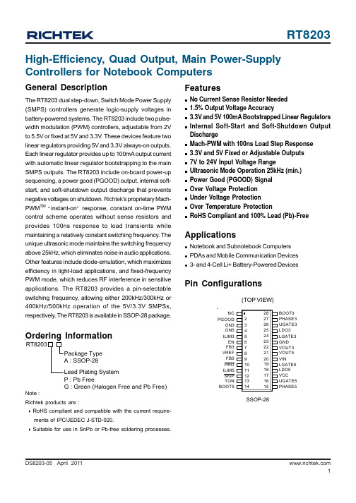
DS8203-05 April 2011Featuresz No Current Sense Resistor Needed z 1.5% Output Voltage Accuracyz 3.3V and 5V 100mA Bootstrapped Linear Regulators zInternal Soft-Start and Soft-Shutdown Output Dischargez Mach-PWM with 100ns Load Step Response z 3.3V and 5V Fixed or Adjustable Outputs z 7V to 24V Input Voltage Rangez Ultrasonic Mode Operation 25kHz (min.)z Power Good (PGOOD) Signal z Over Voltage Protection z Under Voltage Protection z Over Temperature ProtectionzRoHS Compliant and 100% Lead (Pb)-FreeApplicationsz Notebook and Subnotebook Computers z PDAs and Mobile Communication Devices z3- and 4-Cell Li+ Battery-Powered DevicesHigh-Efficiency, Quad Output, Main Power-Supply Controllers for Notebook ComputersOrdering InformationGeneral DescriptionThe RT8203 dual step-down, Switch Mode Power Supply (SMPS) controllers generate logic-supply voltages in battery-powered systems. The RT8203 include two pulse-width modulation (PWM) controllers, adjustable from 2V to 5.5V or fixed at 5V and 3.3V. These devices feature two linear regulators providing 5V and 3.3V always-on outputs.Each linear regulator provides up to 100mA output current with automatic linear regulator bootstrapping to the main SMPS outputs. The RT8203 include on-board power-up sequencing, a power good (PGOOD) output, internal soft-start, and soft-shutdown output discharge that prevents negative voltages on shutdown. Richtek 's proprietary Mach-PWM TM “instant-on ” response, constant on-time PWM control scheme operates without sense resistors and provides 100ns response to load transients while maintaining a relatively constant switching frequency. The unique ultrasonic mode maintains the switching frequency above 25kHz, which eliminates noise in audio applications.Other features include diode-emulation, which maximizes efficiency in light-load applications, and fixed-frequency PWM mode, which reduces RF interference in sensitive applications. The RT8203 provides a pin-selectable switching frequency, allowing either 200kHz/300kHz or 400kHz/500kHz operation of the 5V/3.3V SMPSs,respectively. The RT8203 is available in SSOP-28 package.Pin Configurations(TOP VIEW)NC PGOODON5ON3ILIM3EN FB3VREF FB5ILIM5TON BOOT5BOOT3PHASE3UGATE3LDO3LGATE3GND VOUT3VOUT5VINLGATE5LDO5VCCUGATE5PHASE5PRO SKIP SSOP-28Note :Richtek products are :` RoHS compliant and compatible with the current require-ments of IPC/JEDEC J-STD-020.` Suitable for use in SnPb or Pb-free soldering processes.P : Pb FreeG : Green (Halogen Free and Pb Free)Typical Application CircuitFigure 1. Fixed Voltage Regulator5VVDS8203-05 April 2011Figure 2. Adjustable Voltage Regulator5VV C140.1µFTo be continuedDS8203-05 April 2011Function Block DiagramDS8203-05 April 2011Electrical Characteristics(V= 12V, No load on LDOx, VOUTx and VREF, ONx = VCC, V = 5V, T = 25°C, unless Otherwise specification)Absolute Maximum Ratings (Note 1)zInput Voltage, V IN , EN to GND ------------------------------------------------------------------------------−0.3V to 25V z BOOTx to GND -------------------------------------------------------------------------------------------------−0.3V to 30V z PHASEx to BOOTx --------------------------------------------------------------------------------------------−6V to 0.3V z PHASEx to GND ------------------------------------------------------------------------------------------------−1V to 25V z , PRO, PGOOD to GND ---------------------------−0.3V to 6Vz UGATEx to PHASEx ------------------------------------------------------------------------------------------−0.3V to (V BOOTx + 0.3V)z ILIMx to GND ----------------------------------------------------------------------------------------------------−0.3V to (V CC + 0.3V)z LGATEx to GND ------------------------------------------------------------------------------------------------−0.3V to (V LDO5 + 0.3V)z TON to GND ------------------------------------------------------------------------------------------------------−0.3V to 6V z LDOx, VREF Short Circuit to GND -------------------------------------------------------------------------Momentary z LDOx Circuit (Internal Regulator) Continuous -----------------------------------------------------------100mA z LDOx Circuit (Switchover to VOUTx) Continuous ------------------------------------------------------200mA z Power Dissipation, P D @ T A = 25°CSSOP-28--------------------------------------------------------------------------------------------------------1.053W z Package Thermal Resistance (Note 2)SSOP-28, θJA ----------------------------------------------------------------------------------------------------95°C/W z Junction T emperature ------------------------------------------------------------------------------------------150°C z Lead Temperature (Soldering, 10 sec.)--------------------------------------------------------------------260°Cz Storage T emperature Range ---------------------------------------------------------------------------------–65°C to 150°C z ESD Susceptibility (Note 3)HBM (Human Body Mode)-----------------------------------------------------------------------------------2kV MM (Machine Mode)-------------------------------------------------------------------------------------------200VTo be continuedRecommended Operating Conditions (Note 4)z Input Voltage, V IN -----------------------------------------------------------------------------------------------7V to 24V z Control Voltage, V CC -------------------------------------------------------------------------------------------5V ± 5%z Junction T emperature Range ---------------------------------------------------------------------------------–10°C to 125°C zAmbient T emperature Range ---------------------------------------------------------------------------------–10°C to 85°CTo be continuedDS8203-05 April 2011To be continuedNote 1. Stresses listed as the above“Absolute Maximum Ratings” may cause permanent damage to the device. These are for stress ratings. Functional operation of the device at these or any other conditions beyond those indicated in the operational sections of the specifications is not implied. Exposure to absolute maximum rating conditions for extended periods may remain possibility to affect device reliability.Note 2. θJA is measured in the natural convection at T A = 25°C on a low effective single layer thermal conductivity test board of JEDEC 51-3 thermal measurement standard.Note 3. Devices are ESD sensitive. Handling precaution is recommended.Note 4. The device is not guaranteed to function outside its operating conditions.Note 5. I LDO3 + I LDO5 < 150mANote 6. P VIN + P VCC11DS8203-05 April 2011Typical Operating CharacteristicsNo load on LDO5, LDO3,VOUT5, VOUT3 and REF , T ON = VCC, EN = VIN, T A = 25°C, unless otherwise specified.VOUT5 Efficiency vs. Load Current1020304050607080901000.0010.010.1110Load Current (A)E f f i c i e n c y (%)VOUT5 Efficiency vs. Load Current1020304050607080901000.0010.010.1110Load Current (A)E f f i c i e n c y (%)VOUT3 Efficiency vs. Load Current1020304050607080901000.0010.010.1110Load Current (A)E f f i c i e n c y (%)VOUT3 Efficiency vs. Load Current1020304050607080901000.0010.010.1110Load Current (A)E f f i c i e n c y (%)VOUT5 Efficiency vs. Load Current1020304050607080901000.0010.010.1110Load Current (A)E f f i c i e n c y (%)VOUT3 Efficiency vs. Load Current1020304050607080901000.0010.010.1110Load Current (A)E f f i c i e n c y (%)12DS8203-05 April 2011 VOUT3 Switching Frequency vs. Load Current40801201602002402803203600.0010.010.1110Load Current (A)S w i t c h i n g F r e q u e n c y (k H z )VOUT3 Switching Frequency vs. Load Current40801201602002402803203600.0010.010.1110Load Current (A)S w i t c h i n g F r e q u e n c y (k H z )VOUT5 Switching Frequency vs. Load Current2550751001251501752002252500.0010.010.1110Load Current (A)S w i t c h i n g F r e q u e n c y (k H z )VOUT5 Switching Frequency vs. Load Current2550751001251501752002252500.0010.010.1110Load Current (A)S w i t c h i n g F r e q u e n c y (k H z )VOUT5 Switching Frequency vs. Load Current2550751001251501752002252500.0010.010.1110Load Current (A)S w i t c h i n g F r e q u e n c y (k H z )VOUT3 Switching Frequency vs. Load Current40801201602002402803203600.0010.010.1110Load Current (A)S w i t c h i n g F r e q u e n c y (k H z )13DS8203-05 April 2011LDO5 Output Voltage vs. Output Current4.854.904.955.005.055.10102030405060708090100Output Current (mA)O u t p u t V o l t a g e (V)LDO3 Output Voltage vs. Output Current3.203.253.303.353.403.453.500102030405060708090100Output Current (mA)O u t p u t V o l t a g e (V)V REF vs. Output Current1.9891.9911.9931.9951.9971.9992.0012.0032.005-10102030405060708090100Output Current (uA)V R E F (V)V IN Standby Input Current vs. Input Voltage210212214216218220222224226228230791113151719212325Input Voltage (V)V I N S t a n d b y I n p u t C u r r e n t (u A)V IN Shutdown Input Current vs. Input Voltage1011121314151617181920791113151719212325Input Voltage (V)V I N S h u t d o w n I n p u t C u r r e n t (u A)No Load V IN Current vs. Input Voltage0.1110100791113151719212325Input Voltage (V)N o L o a d V I N C u r r e n t (m A )14DS8203-05 April 2011 V IN = 12V, ON3 = ON5 = GND Power UpTime (400μs/Div)LDO3(2V/Div)LDO5(2V/Div)V IN (10V/Div)REF (2V/Div)VOUT3(2V/Div)VOUT5(2V/Div)ON5(5V/Div)V IN = 12V, ON3 = REFDelayed StartTime (400μs/Div)V IN = 12V, ON5 = REF Delayed StartTime (400μs/Div)VOUT3(2V/Div)VOUT5(2V/Div)ON3(5V/Div)V IN = 12V, ON3 = ON5 = VCCShutdown ResponseTime (10ms/Div)UGATE5(20V/Div)VOUT5(5V/Div)ON5(10V/Div)LGATE5(5V/Div)SKIP = VCC(Forced CCM Mode)ON3 = ON5 = VCC, C OUT = 330μF, L = 7.6μHVOUT5 Load Transient ResponseTime (20μs/Div)Inductor Current (5A/Div)V OUT_ac-coupled (100mV/Div)LGATE5(5V/Div)V IN = 12V, SKIP = VCC(Forced CCM Mode)Inductor Current (5A/Div)V OUT_ac-coupled (100mV/Div)LGATE3(5V/Div)ON3 = ON5 = VCC, C OUT = 470μF, L = 4.7μHVOUT3 Load Transient ResponseTime (10μs/Div)V IN = 12V, SKIP = VCC(Forced CCM Mode)15DS8203-05 April 2011V IN = 12V, ON3 = ON5 = VCCVOUT5 OVPTime (2ms/Div)LGATE5(5V/Div)VOUT5(5V/Div)LGATE3(10V/Div)VOUT3(2V/Div)SKIP = GND(Diode-Emulation Mode)V IN = 12V, ON3 = ON5 = VCCVOUT5 UVPTime (10μs/Div)UGATE5(20V/Div)VOUT5(5V/Div)LGATE5(5V/Div)Inductor Current (10A/Div)SKIP = VCC(Forced CCM Mode)V IN = 12V, C OUT = 330μF, L = 7.6μHVOUT5 Shorted Start UpTime (2ms/Div)UGATE5(20V/Div)VOUT5(2V/Div)LGATE5(5V/Div)Inductor Current (5A/Div)VOUT5 Shorted, SKIP = VCC(Forced CCM Mode)16DS8203-05 April 2011 Application InformationThe RT8203 is a dual, Mach Response TM DRV TM dual ramp valley mode synchronous buck controller. The controller is designed for low voltage power supplies for notebook computers. Richtek's Mach Response TM technology is specifically designed for providing 100ns “instant-on ”response to load steps while maintaining a relatively constant operating frequency and inductor operating point over a wide range of input voltages. The topology circumvents the poor load transient timing problems of fixed-frequency current mode PWMs while avoiding the problems caused by widely varying switching frequencies in conventional constant-on-time and constant off-time PWM schemes. The DRV TM mode PWM modulator is specifically designed to have better noise immunity for such a dual output application. The RT8203 includes 5V (LDO5) and 3.3V (LDO3) linear regulators. LDO5 linear regulator can step down the battery voltage to supply both internal circuitry and gate drivers. The synchronous-switch gate driver s are directly powered from LDO5. When VOUT5voltage is above 4.65V, an aut omatic circuit turns off the LDO5 linear regulator and powers the device form VOUT5.PWM OperationThe Mach Response TM DRV TM mode controller relies on the output filter capacitor's effective series resistance (ESR)to act as a current sense resistor, so the output ripple voltage provides the PWM ramp signal. Refer to the RT8203's function block diagram, the synchronous high side MOSFET is turned on at the beginning of each cycle.After the internal one-shot timer expires, the MOSFET is turned off. The pulse width of this one shot is determined by the converter's input voltage and the output voltage to keep the frequency fairly constant over the input voltage range. Another one shot sets a minimum off-time (400ns typ). The on-time one shot is triggered if the error comparator is high, the low side switch current is below the current limit threshold, and the minimum off-time one shot has timed out.PWM Frequency and On-Time ControlThe Mach Response TM control architecture runs with pseudo-constant frequency by feed forwarding the input and output voltage into the on-time one shot timer. TheOUT DROP1ON IN DROP2(V + V )f =t x (V +V )high side switch on-time is inversely proportional to the input voltage as measured by the V IN , and proportional to the output voltage. There are two benefits of a constant switching frequency. The first is the frequency can beselected to avoid noise sensitive regions such as the 455kHz IF band. The second is the inductor ripple-current operating point remains relatively constant, resulting in easy design methodology and predictable output voltage ripple.The frequency for 5V SMPS is set at 100kHz higher than the frequency for 3V SMPS. This is done to prevent audio-frequency “beating ” between the two sides, which switch asynchronously for each side. The on-time is given by :On-Time = K ( V OUT / V IN )where K is set by the TON pin-strap connection (Table 1).The on-times guaranteed in the Electrical Characteristics tables are influenced by switching delays in the external high-side power MOSFET. Two external factors that influence switching frequency accuracy are resistive drops in the two conduction loops (including inductor and PC board resistance) and the dead-time effect. These effects are the largest contributors to the change of frequency with changing load current. The dead time effect increases the effective on-time, reducing the switchi ng frequency as one or both dead times. It occurs only in Forced CCM Mode (SKIP = high) when the inductor cu rrent reverses at light or negative load currents. With reversed inductor current, the inductor ’s EMF causes PHASEx to go high earlier than normal, extending the on-time by a period equal to the low-to-high dead time. For loads above the critical conduction point, the actual switching frequency is :where V DROP1 is the sum of the parasitic voltage drops in the inductor discharge path, including synchronous rectifier,inductor, and PC board resistances; V DROP2 is the sum of the resistances in the charging path; and t ON is the on-time calculated by the RT8203.Operation Mode Selection (SKIP)The RT8203 supports three operation modes: Diode-Emulation Mode, Ultrasonic Mode, and Forced-CCM Mode.17DS8203-05 April 2011Diode-Emulation Mode ( SKIP = GND)In Diode-Emulation mode, RT8203 automatically reduces switching frequency at light load conditions to maintain high efficiency. This reduction of frequency is achieved smoothly and without increase of V OUT ripple or load regulation. As the output current decreases from heavyload condition, the inductor current is also reduced, and eventually comes to the point that its valley touches zero current, which is the boundary between continuous conduction and discontinuous conduction modes. By emulating the behavior of diodes, the low side MOSFET a llows only partial of negative current when the inductor free-wheeling current reach negative. As the load current further decreases, it takes longer and longer to discharge the output capacitor to the level that requires the next “ON ” cycle. The on-time is kept the same as that in the heavy load condition. In reverse, when the output current increases from light load to heavy load, the switching frequency increases to the preset value as the inductor current reaches the continuous conduction. The transition load point to the light load operation can be calculated as follows (Figure 3) :t= i L, peak / 2Figure 3. Boundary Condition of CCM/DCMIN OUT LOAD(SKIP)ON(V - V )It 2L≈×where Ton is the On-time.The switching waveforms may appear noisy and asynchronous when light loading causes Diode-Emulation operation, but this is a normal operating condition that results in high light load efficiency. Trade-offs in PFM noise vs. light-load efficiency are made by varying the inductor value. Generally, low inductor values produce a broader efficiency vs. load curve, while higher values result in higher full-load efficiency (assuming that the coil resistance remains fixed) and less output voltage ripple. Penalties forusing higher inductor values include larger physical size and degraded load transient response (especially at low input-voltage levels).Ultrasonic Mode ( SKIP = Float)Leaving SKIP unconnected or connecting SKIP to VREF activates a unique Diode-Emulation mode with a minimum switching frequency of 25kHz. This ultrasonic mode eliminates audio-frequency modulation that would otherwise be present when a lightly loaded controller automatically skips pulses. In ultrasonic mode, the low-side switch gate-driver signal is OR with an internal oscillator (>25kHz). Once the internal oscillator is triggered, the ultrasonic controller pulls LGATEx high, turning on the low side MOSFET to induce a negative inductor current. After the output voltage across the VREF, the controller turns off the low side MOSFET (LGATEx pulled low) and triggers a constant on-time (UGATEx driven high). When the on-time has expired, the controller re-enables the low-side MOSFET until the controller detects that the inductor cur rent drops belo w the zero-crossing threshold.Forced-CCM Mode ( SKIP = VCC)The low noise, forced-CCM mode ( SKIP = VCC) disables the zero-crossing comparator, which controls the low-side switch on-time. This causes the low side gate-driver waveform to become the complement of the high side gate-driver waveform. This in turn causes the inductor current to reverse at light loads as the PWM loop strives to maintain a duty ratio of V OUT /V IN . The benefit of forced-CCM mode is to keep the switching frequency fairly constant, but it comes at a cost: The no-load battery current can be 10mA to 40mA, depending on the external MOSFETs.Reference and linear Regulators (VREF, LDOx)The 2V reference (VREF) is accurate within ± 1% over temperature, making VREF useful as a precision system reference. Bypass VREF to GND with 0.22μF(min)capacitor. VREF can supply up to 100uA for external loads.Loading VREF reduces the VOUTx output voltage slightly because of the reference load-regulation error.LDO5 regulator supplies total of 100mA for internal and external loads, including MOSFET gate driver and PWM controller. LDO3 regulator supplies up to 100mA for external loads. Bypass LDO5 and LDO3 with a minimum 4.7uF18DS8203-05 April 2011 Figure 4. “Valley ” Current LimitItThe RT8203 uses the on-resistance of the synchronous rectifier as the current sense element. Use the worse-case maximum value for R DS(ON) from the MOSFET data sheet,and add a margin of 0.5%/°C for the rise in R DS(ON) with temperature.The current limit threshold is adjusted with an external voltage divider at ILIMx. The current limit threshold adjustment range is from 50 mV to 200mV. In the adjustable mode, the current limit threshold voltage is precisely 1/10the voltage seen at ILIMx. The threshold defaults to 100mVV Figure 5. Reducing the UGATEx Rise Timeload; use an additional 1μF per 5mA of internal and external load.When the 5V main output volta ge is above the LDO5switchover threshold, an internal 1.4Ω N-MOSFET switch connects VOUT5 to LDO5 while simultaneously shutting down the LDO5 linear regulator. Similarly, when the 3.3V main output voltage is above the LDO3 switchover threshold, an internal 1.5Ω N-MOSFET switch connects VOUT3 to LDO3 while simultaneously shutting do wn the LDO3 linear regulator. It can decrease the power dissipation from the same battery, because the converted efficiency of SMPS is better than the converted efficiency of linear regulator.Current Limit Setting (ILIMx)The RT8203 has cycle-by-cycle current limiting control.The current limit circuit employs a unique “valley ” current sensing algorithm. If the magnitude of the current sense signal at PHASEx is above the current limit threshold, the PWM is not allowed to initiate a new cycle (Figure 4). The actual peak current is greater than the current limit threshold by an amount equal to the inductor ripple current. Therefore,the exact current limit characteristic and maximum load capability are a function of the sense resistance, inductor value, and battery and output voltage.when ILIMx is connected to VCC. The logic threshold for switchover to the 100mV default value is approximately VCC - 1V.Carefully observe the PC board layout guidelines to ensure that noise and DC errors do not corrupt the current-sense signal at PHASEx and GND. Mount or place the IC close to the low side MOSFET .MOSFET Gate Driver (UGATEx, LGATEx)The high side driver is designed to drive high current, low R DS(on) NMOSFET(s). When configured as a floating driver,5-V bias voltage is delivered from LDO5 supply. The average drive current is also calculated by the gate charge at V GS = 5 V times switching frequency. The instantaneous drive current is supplied by the flying capacitor between BOOTx and PHASEx pins. A dead time to prevent shoot through is internally generated between high side MOSFET off to low side MOSFET on, and low side MOSFET off to high side MOSFET on.The low side driver is designed to drive high current low R DS(on) NMOSFET(s). The internal pull-down transistor that drives LGATEx low is robust, with a 0.6Ω typical on-resistance. A 5V bias voltage is delivered from LDO5supply.For high current applications, some combinations of high and low side M OSFETs may caus e excessive gate-drain coupling, which can lead to efficiency-killing and EMI-producing shoot-through currents. This is often remedied by adding a resistor in series with BOOTx, which increases the turn-on time of the high side MOSFET without degrading the turn-off time (Figure 5).19DS8203-05 April 2011Soft-StartA build-in soft-start is used to prevent surge current from power supply input after ONx is enabled. It clamps the ramping of internal reference voltage which is compared with the FBx signal. The typical soft-start duration is 1.5ms period. Furthermore, the maximum allowed current limit is segmented in 3 steps : 20%, 50%, and 100% during the 1.5ms period. The current limit steps can minimize the V OUT folded-back in the soft-start duration when RT8203is determining fixed or adjustable output.POR and UVLOPower On Reset (POR) occurs when V IN rises above approximately 3.5V, resetting the fault latch and preparing the PWM for operation. Below 4.25V(min), the VCC undervoltage lockout (UVLO) circuitry inhibits switching by keeping UGATEx and LGATEx low.Power Good Output (PGOOD)The PGOOD is an open-drain type output. PGOOD is actively held low in soft-start, standby, and shutdown. It is released when both outputs voltage above than 91.25% of nominal regulation point. The PGOOD goes low if either output turns of or is 8.75% below its n ominal regulation point.Output Over Voltage Protection (OVP)The output voltage can be continuously monitored for over voltage. When over voltage protection is enabled, if the output exceeds the over voltage threshold, over voltage fault protection is triggered and the LGATEx low side gate drivers are forced high. This activates the low side MOSFET switch, which rapidly discharges the output capacitor and reduces the input voltage.Note that LGATEx latching high causes the output voltage to dip slightly negative when energy has been previously stored in the LC tank circuit. For loads that cannot tolerate a negative voltage, place a power Schottky diode across the output to act as a reverse polarity clamp. Connect PRO to G ND to enable the default over voltage threshold level,which is 11% above the s et voltage.If the over voltage condition is caused by a short in high side switch, turning the low side MOSFET on 100% creates an electrical short between the battery and GND, blowing the fuse and disconnecting the battery from the output.Output Under Voltage Protection (UVP)The output voltage can be continuously monitored for under voltage. When under voltage protection is enabled ( PRO = GND), if the output is less than 70% of the error-amplifier trip voltage, under voltage protection is triggered, then both UGATEx and LGATEx gate drivers are forced low. In order to remove the residual charge on the output capacitor during the UV period, if PHASEx is greater than 1V, the LGATEx gate driver is forced high until PHASEx lower than 1V.Connect UVP to GND to disable under voltage protection.Thermal ProtectionThe RT8203 have thermal shutdown to prevent the overheat damage. Thermal shutdown occurs when the die temperature exceeds 150°C. All internal circuitry shuts down during thermal shutdown. The RT8203 will trigger thermal shutdown if LDOx is not supplied from VOUTx,while input voltage on VIN and drawing current form LDOx are too high. Even if LDOx is supplied from VOUTx,overloading the LDOx causes large power dissipation on automatic switches, which may result in thermal shutdown.Discharge ModeWhen PRO is low and a transition to standby or shutdown mode occurs, or the output under voltage fault latch is set, the outputs discharge mode is triggered. During discharge mode, there are two paths to discharge the outputs capacitor residual charge during discharge mode.The first is output capacitor discharge to GND through an internal 17Ω switch. The second is output capacitor discharged by forcing the low-side MOSFET turn on/off until PHASEx voltage decrease under 1V.Shutdown ModeDrive EN below the precise EN input falling-edge trip level to place the RT8203 in their low-power shutdown state.When shutdown mode activates, the reference turns off,making the threshold to exit shutdown inaccurate. For automatic shutdown and startup, connect EN to VIN. If PRO is low, both SMPS outputs will enter discharge mode before entering true shutdown. The accurate 1V falling-edge threshold on EN can be used to detect a specific analog voltage level and shutdown the device. Once in shutdown, the 1.6V rising-edge threshold activates,providing sufficient hysteresis for most application.。
8203是什么意思
8203是什么意思
1、8203是网络流行语,是“不要离散”的含义,表达的是恋人吵架或分手时一方对另一方的挽留,常用于QQ、MSN等即时聊天工具。
2、用手摆出“ 八”“二”“零”“三”,便会发现八、二、零、三分别是L、O、V、E。
这是宋晓波的手语书中的一个经典数字手语用手比划即可得知:“8”,把左手大拇指和食指叉开,竖放代表“L”;“0”,代表“O”;“2”,叉开食指和中指,代表“V”;“3”,叉开中指、无名指、小拇指,横放代表“E”.合起来就是“LOVE”.
数字释义:0代表完美、圆满、无止境;1代表唯一,你和起点;2代表爱情,两个人的世界。
3代表思念,生命,生活;4表示是,一直是;5代表我,无;6代表平稳,漫步;7代表讨好、亲吻、起身、生气、溜走;8表示发送,拜拜,不;9代表长久、公正和追求。
类似8203的数字意思:
1、8006:不理你了。
2、8013:伴你一生。
3、8074:把你气死。
4、8084:BABY。
5、81176:不要在一起了。
6、82475:被爱是幸福。
7、825:别爱我。
8、837:别生气。
9、898:分手吧。
10、8834760:长相思只为你。
tpc8203参数
tpc8203参数TPC8203是一款高性能的处理器,其参数设计使其在各种应用场景下表现出色。
本文将对TPC8203的参数进行详细介绍,并探讨其在实际应用中的优势。
TPC8203采用了先进的制程工艺,拥有强大的计算能力和高效的能耗控制。
它搭载的多核处理器架构能够实现多任务并行处理,提高系统的整体性能。
而且,TPC8203还支持超线程技术,可以使每个物理核心模拟出多个逻辑核心,进一步提升系统的处理能力。
TPC8203具备丰富的外设接口和高速通信接口,使其能够应对各种复杂的应用场景。
它支持多种外设接口,如USB、SPI、I2C等,可以连接各种传感器、摄像头、显示器等设备。
此外,TPC8203还支持高速以太网接口,可以实现快速的数据传输和网络通信。
TPC8203还具备强大的图形处理能力,可实现高清视频播放和图形渲染。
它采用了先进的图形处理单元,支持多种图形和视频编解码格式,可以实现流畅的高清视频播放和逼真的图形渲染效果。
这使得TPC8203在广告机、智能监控、游戏机等应用领域具有巨大的潜力。
TPC8203还支持多种操作系统,如Linux、Android等,为开发者提供了灵活的开发环境。
开发者可以根据自己的需求选择适合的操作系统,并利用丰富的软件资源进行应用开发。
这样一来,开发者可以更加高效地开发出各种应用,满足用户的需求。
在实际应用中,TPC8203的参数设计使其具备广泛的适应性和稳定性。
它可以应用于智能家居、工业自动化、智能交通等领域,为各种应用提供强大的计算和处理能力。
而且,TPC8203还具备低功耗特性,可以在长时间运行的应用场景下保持系统的稳定性和可靠性。
TPC8203是一款具有强大性能和丰富功能的处理器。
它的参数设计使其在各种应用场景下表现出色,为用户提供了高效的计算和处理能力。
无论是在智能家居、工业自动化还是智能交通领域,TPC8203都能发挥出强大的优势,为各种应用提供可靠的支持。
相信随着技术的不断进步和应用领域的不断扩大,TPC8203将在未来发展中展现出更加广阔的前景。
8203是什么意思
8203是什么意思1. 背景介绍8203是一个看似普通的数字,然而它在某些领域里被赋予了特殊的意义和用途。
那么,8203到底是什么意思呢?本文将介绍8203在编码、作为特殊符号以及在网络通信中的用途等方面的具体含义和解释。
2. 8203的编码含义在Unicode编码中,8203被称为零宽空格(Zero Width Space),它的Unicode编码为U+200B。
零宽空格是一种特殊的不可见字符,用于在文本中插入空白,但不产生显示效果。
它可以用于调整文本的格式和排版,尤其在网页设计和文档编辑中常被使用。
3. 8203的作为特殊符号除了编码上的含义,8203还被用作特殊符号。
在某些场景下,人们使用8203来表示一些特定的含义或表示状态。
以下是一些常见的使用情况:•密码保密性标记:在某些在线平台或论坛中,用户可能会使用8203来隐藏密码或敏感信息。
通过将密码中的某些字符替换为8203,可以降低密码被泄露的风险。
•文本屏蔽和敏感词过滤:一些社交媒体或敏感信息平台会使用8203来屏蔽或过滤敏感词汇。
通过将敏感词汇中的某些字符替换为零宽空格,可以有效地防止这些词汇的出现。
•隐写术: 8203也可以用于隐写术中的文本隐藏。
通过在文本中插入8203,可以将隐藏的信息嵌入到正常的文本中,从而实现秘密通信或隐藏信息的目的。
4. 8203在网络通信中的意义在网络通信中,8203起到了重要的作用。
以下是一些与网络通信相关的场景:•网页链接的跟踪:当您在发送电子邮件或社交媒体消息时,URL的后面可能会跟着一些字符,其中就包括8203。
这些字符通常被用于追踪链接的点击次数,跟踪用户的行为以及分析网页流量等。
•特殊字符的编码:一些特殊字符在传输过程中可能会发生编码问题,造成显示异常或乱码。
通过在字符前后插入8203,可以解决这些编码问题并正确地显示这些字符。
•文本消息的空白分隔:在某些聊天应用程序中,为了增加消息的阅读性和美观度,会在消息之间插入8203来分隔消息。
dm8203iep规格书

dm8203iep规格书DM8203IEP规格书一、引言DM8203IEP是一款电子产品,被广泛应用于各种领域,如通信、嵌入式系统、工业控制等。
本文将详细介绍DM8203IEP的规格和特性。
二、规格概述1. 处理器:DM8203IEP采用先进的处理器,具有强大的计算能力和高效的功耗管理。
2. 存储器:DM8203IEP配备了大容量的内存和存储空间,可满足各种应用需求。
3. 通信接口:DM8203IEP支持多种通信接口,如以太网、USB、RS232等,方便与其他设备进行数据交互。
4. 显示屏:DM8203IEP配备了高清晰度的显示屏,可呈现清晰、逼真的图像。
5. 操作系统:DM8203IEP支持多种操作系统,如Linux、Windows 等,可根据用户需求进行选择和定制。
6. 电源管理:DM8203IEP具有优良的电源管理系统,能够实现节能和智能电源管理。
三、性能指标1. 处理性能:DM8203IEP具有出色的处理性能,能够快速响应用户指令。
2. 存储性能:DM8203IEP的存储性能优异,可实现高速读写和数据传输。
3. 图像处理能力:DM8203IEP具备强大的图像处理能力,能够实现高清晰度的图像显示和处理。
4. 通信性能:DM8203IEP的通信接口稳定可靠,能够实现快速且安全的数据传输。
5. 电源管理性能:DM8203IEP的电源管理系统智能高效,能够实现电源的智能管理和节能。
四、应用领域DM8203IEP广泛应用于以下领域:1. 通信领域:DM8203IEP可用于通信设备的控制和数据处理,提高通信系统的性能和可靠性。
2. 嵌入式系统:DM8203IEP可应用于各种嵌入式系统,如智能家居、智能电网等,实现智能化控制和管理。
3. 工业控制:DM8203IEP在工业控制领域具有广泛的应用,如自动化生产线、机器人控制等,提高生产效率和质量。
4. 智能交通:DM8203IEP可用于交通信号控制、车辆跟踪等应用,提高交通系统的安全性和效率。
ADC0832中文资料

A/D 转换芯片ADC0832的应用作者:杜洋 2005年10月11日ADC0832是美国国家半导体公司生产的一种8位分辨率、双通道A/D 转换芯片。
由于它体积小,兼容性强,性价比高而深受单片机爱好者及企业欢迎,其目前已经有很高的普及率。
学习并使用ADC0832可是使我们了解A/D 转换器的原理,有助于我们单片机技术水平的提高。
ADC0832具有以下特点:· 8位分辨率;· 双通道A/D 转换;· 输入输出电平与TTL/CMOS 相兼容; · 5V 电源供电时输入电压在0~5V 之间; · 工作频率为250KHZ ,转换时间为32μS ; · 一般功耗仅为15mW ;· 8P 、14P —DIP (双列直插)、PICC 多种封装;· 商用级芯片温宽为0°C to +70°C ,工业级芯片温宽为−40°C to +85°C ;芯片顶视图:(图1、图2)图1 图2ww w .t ai -ya n.c o m /bb s 电子工程技术论坛:IC资料查询网站:电子器件采购平台: /bbs芯片接口说明:·CS_ 片选使能,低电平芯片使能。
· CH0 模拟输入通道0,或作为IN+/-使用。
· CH1 模拟输入通道1,或作为IN+/-使用。
· GND 芯片参考0电位(地)。
· DI 数据信号输入,选择通道控制。
· DO 数据信号输出,转换数据输出。
· CLK 芯片时钟输入。
· Vcc/REF 电源输入及参考电压输入(复用)。
ADC0832与单片机的接口电路:图3ww w .t a i -y a n .c o m /bb s 电子工程技术论坛:IC资料查询网站:电子器件采购平台: /bbsADC0832为8位分辨率A/D 转换芯片,其最高分辨可达256级,可以适应一般的模拟量转换要求。
