Keysight 技术更新服务
Keysight N9020A MXA X系列信号分析仪技术资料说明书

Keysight N9020A MXAX 系列信号分析仪10 Hz~3.6、8.4、13.6 或26.5 GHz技术资料目录定义与条件 (3)频率和时间技术指标 (4)幅度精度与范围技术指标 (6)动态范围技术指标 (8)PowerSuite 测量技术指标 (12)一般技术指标 (13)输入和输出 (14)IQ 分析仪 (16)IQ 分析仪-选件B40 (17)IQ 分析仪-选件B85/B1A/B1X (18)实时频谱分析仪(RTSA) (19)相关文献 (19)本技术资料是 MXA 信号分析仪的技术指标和条件摘要。
如欲获取完整的技术指标指南,请访问: /find/mxa_specifications 加速上市每个器件都需要您在客户技术指标、吞吐量和产率等目标之间做出权衡。
借助高度灵活的信号分析仪,您可以管理并最大程度地保证所有目标。
是德科技中档MXA 是您的终极加速器,可帮助您加快产品从设计到上市的速度。
它还具有出色的灵活性,可以迅速适应用户不断变化的测试要求―包括当前的要求和未来的要求。
借助是德科技MXA 信号分析仪,您可以最大限度地提升灵活性并缩短产品上市时间。
定义与条件技术指标是指产品保证中所包括的参数性能,除非特别注明,这些技术指标只在0°C 到55°C1的完整温度范围内有效。
95% 表示环境温度在20 至30°C 内时,预计有95% 的把握在95% 的情况下能够达到性能容限范围(~ 2σ)。
除了仪器样品的统计观测数据之外,这些值还包括外部校准参考的不确定度影响。
我们不保证仪器性能可以达到这些参数值。
如果生产仪器的统计观测特性出现重大变化,有时候会对这些值进行更新。
典型值是指不在产品保修范围内的其它产品性能信息。
当性能超出技术指标时,80% 的样本在20~30°C 的温度范围内可表现出95% 的置信度。
典型性能不包括测量不确定度。
标称值是指预计的性能,或表示在产品应用中有用但未包含在产品保修范围内的产品性能。
薄型模块式电源系统 N6700 系列用户指南说明书
用户指南Keysight Technologies 薄型模块式电源系统N6700系列法律声明© Keysight Technologies 2006 - 2014根据美国和国际版权法,未经Keysight Technologies 事先同意和书面许可,本文档的任何部分不得影印、复制或翻译成其他语言。
担保本文档中包含的材料“按原样”提供,如有更改,恕不另行通知。
此外,在适用法律所允许的最大范围内,Keysight 对与此手册相关的内容及其中所含的信息不作任何明示或默示的保证,包括但不限于对适销性和适用于特定目的所作的默示保证。
Keysight 对与提供、使用本手册及其所含信息以及与执行手册中的步骤有关的任何错误或偶然及继发性损坏不承担任何责任。
如果Keysight 与用户之间单独签定的协议中的保证条款涉及本文档中的内容,并且与本文档中的条款相抵触,则应以单独协议中的保证条款为准。
手册版本手册部件号:5969-2937CH第8版,2014年11月马来西亚印刷。
本手册的重印版包含少量更正和更新,可能具有相同的印刷日期。
修订版则标有新的印刷日期。
遵从有关标准的声明本产品和其他Keysight 产品的“遵从有关标准的声明”可以从Web 中下载。
请访问/go/conformity,然后单击“Declarations of Conformity”。
然后,您可以按产品编号进行搜索,找到最新的“遵从有关标准的声明”废弃电子电气设备 (WEEE) 指令2002/96/EC本产品符合 WEEE 指令 (2002/96/EC) 市场营销要求。
贴附于产品上的标签(请见下方)指示,不得将本电子/电气产品随同家庭废弃物一起处理。
产品类别:根据WEEE 指令Annex 1中的设备类型分类,此产品被归类为“监测和控制仪器”产品。
请勿作为家庭废弃物处理。
要退回不需要的产品,请与当地的Keysight 办事处联系,或访问/environment/product以了解详细信息。
是德科技keysight34420a纳伏表微欧计使用手册说明书技术指标,原安捷伦agilent
Agilent 34420A 纳伏/微欧表7 1/2位分辨率100pV/100n Ω灵敏度1.3 nVrms / 8 nVpp 噪声性能内装低噪声2通道扫描器直接SPRT , RTD , 热敏电阻和热偶测量微伏级的价格,纳伏级的性能Agilent 34420A 纳伏/微欧表是适用于进行低电平测量的高灵敏多用表。
它把低噪声电压测量与电阻和温度功能结合在一起,建立了灵活的低电平测量和高性能的新标准。
去掉低电平测量的不确定性低噪声输入放大器和高调谐输入保护方案把读数噪声降到8nVpp 。
再加上71/2位分辨率,可选的模拟和数字滤波器,2ppm 24小时基本dcV 精度,屏蔽,以及铜引脚连接器,使您能得到可信赖的精确和可重复的测量结果。
两个输入通道集成的两通道可编程扫描器简化了电压比较。
内置的比率及差值功能可实现自动的两通道测量,而不需要外部纳伏扫描器。
这两个通道共享同样的低噪声特性,以保证精确的比较。
内置的电阻和温度测量34420A 把低噪声纳伏输入与高稳定度电流源相组合,以提供精密的低电平电阻测量 ── 从而避免了外电流源的成本和复杂性。
所包括的三种电阻模式为:标准低功率限制电压,用于固体电路测试也提供最小化EMF 和相关误差的偏置比较。
SPRT 测量内置的I T S -90转换例程使用您SPRD 探头的校准系数,以进行直接的温度测量和转换。
也支持热偶、热敏电阻和RTD 温度测量。
无与伦比的多用性34420A 为您提供众多的测量能力,使您能应对包括工作台和自动系统的各种挑战性任务。
标准特性包括RS-232和GPIB 接口,SCPI 和Keithley 181编程语言,1024读数存储器,标度和统计,以及图形记录仪模拟输出。
Agilent IntuiLink:容易的数据访问所包括的Agilent Intuilink 软件使您能容易地应用所捕获的数据,用Microsoft Excel ®或Word ®这类PC 应用程序分析、翻译、显示、打印和建档来自34420A 的数据。
Keysight InfiniiVision示波器应用软件选项配置指南说明书

配置指南InfiniiVision 软件订购指南应用软件选件InfiniiVision 示波器支持六种应用软件包和一个软件包捆绑套件。
应用软件包支持的领域包括汽车、航空航天与国防、嵌入式设计、电源测试、USB 2.0 和 NFC 测量应用。
与市场上的其他示波器软件选件不同,您无需操心需要为示波器选购单独的协议和高级分析功能。
每个 InfiniiVision 软件包选件都包含一系列串行协议和高级测量功能,针对特定行业应用进行了专门优化。
例如,当今的汽车串行总线测试涉及到多种总线协议和功能。
InfiniiVision 示波器的汽车软件选件支持汽车电子串行总线测试所需的触发、解码和分析等功能,具体包括CAN、CAN FD、LIN、CXPI、FlexRay、SENT、PSI5(用户可自定义的曼彻斯特编码)、用户可自定义的 NRZ、模板极限测试和频率响应分析(波特图)。
此外,您购买是德科技的一个软件包中所包括的一系列测量功能和协议,其价格可能还不到其他供应商一个协议选件的价格。
如果您正在测试嵌入式设计,那么有可能需要在常用的串行总线上进行触发和解码,包括 I2C、SPI 和 UART/RS232/RS485。
虽然专用的协议分析仪器(例如 I2C)可能会满足您当前的嵌入式项目之需,但您的下一个嵌入式项目可能需要 UART、SPI 或I2S 支持。
这个嵌入式软件选件支持各种触发和解码协议,以及先进的测量功能。
本文在下面概括介绍了 InfiniiVision 示波器的可选软件包,并通过表格列出了每个的协议和高级测量功能、订购号以及与不同 Keysight InfiniiVision X 系列示波器的兼容性。
关于这些可选软件的详细信息,请参阅本文档末尾附近列出的技术资料。
汽车软件套件Keysight InfiniiVision 示波器的汽车软件包能够对当今汽车动力总成系统以及车身控制与监测系统中最常用的汽车串行总线进行协议触发和解码。
Intel USB4 评估坞站更新手册说明书

Intel USB4 Evaluation Dock Update ManualINFORMATION IN THIS DOCUMENT IS PROVIDED IN CONNECTION WITH INTEL® PRODUCTS. NO LICENSE, EXPRESS OR IMPLIED, BY ESTOPPEL OR OTHERWISE, TO ANY INTELLECTUAL PROPERTY RIGHTS IS GRANTED BY THIS DOCUMENT. EXCEPT AS PROVIDED IN INTEL'S TERMS AND CONDITIONS OF SALE FOR SUCH PRODUCTS, INTEL ASSUMES NO LIABILITY WHATSOEVER, AND INTEL DISCLAIMS ANY EXPRESS OR IMPLIED WARRANTY RELATING TO SALE AND/OR USE OF INTEL PRODUCTS, INCLUDING LIABILITY OR WARRANTIES RELATING TO FITNESS FOR A PARTICULAR PURPOSE, MERCHANTABILITY, OR INFRINGEMENT OF ANY PATENT, COPYRIGHT, OR OTHER INTELLECTUAL PROPERTY RIGHT.A "Mission Critical Application" is any application in which failure of the Intel Product could result, directly or indirectly, in personal injury or death. SHOULD YOU PURCHASE OR USE INTEL'S PRODUCTS FOR ANY SUCH MISSION CRITICAL APPLICATION, YOU SHALL INDEMNIFY AND HOLD INTEL AND ITS SUBSIDIARIES, SUBCONTRACTORS AND AFFILIATES, AND THE DIRECTORS, OFFICERS, AND EMPLOYEES OF EACH, HARMLESS AGAINST ALL CLAIMS COSTS, DAMAGES, AND EXPENSES AND REASONABLE ATTORNEYS' FEES ARISING OUT OF, DIRECTLY OR INDIRECTLY, ANY CLAIM OF PRODUCT LIABILITY, PERSONAL INJURY, OR DEATH ARISING IN ANY WAY OUT OF SUCH MISSION CRITICAL APPLICATION, WHETHER OR NOT INTEL OR ITS SUBCONTRACTOR WAS NEGLIGENT IN THE DESIGN, MANUFACTURE, OR WARNING OF THE INTEL PRODUCT OR ANY OF ITS PARTS.Intel may make changes to specifications and product descriptions at any time, without notice. Designers must not rely on the absence or characteristics of any features or instructions marked "reserved" or "undefined". Intel reserves these for future definition and shall have no responsibility whatsoever for conflicts or incompatibilities arising from future changes to them. The information here is subject to change without notice. Do not finalize a design with this information.The products described in this document may contain design defects or errors known as errata which may cause the product to deviate from published specifications. Current characterized errata are available on request. Contact your local Intel sales office or your distributor to obtain the latest specifications and before placing your product order. Copies of documents which have an order number and are referenced in this document, or other Intel literature, may be obtained by calling 1-800-548-4725, or goto: /design/literature.htm.All information provided related to future Intel products and plans is preliminary and subject to change at any time, without notice.Intel and the Intel logo are trademarks or registered trademarks of Intel Corporation or its subsidiaries in the United States and other countries.* Other names and brands may be claimed as the property of others.Copyright © 2020, Intel Corporation. All rights reserved.Important: Intel USB4 Evaluation Dock should be Powered off (No Power Supply must be Connected to the Board) when updating FW1.Equipment:1.1Dediprog SF600 (used to update the following components on the Intel USB4 EvaluationDock):Goshen Ridge: U8 – GR NVMDelta Bridge: UB10 – DB NVMUSB2.0 Hub: UB6 – USB2 HUB NVMFigure 1: Dediprog SF600SF600 SPI NOR Flash Programmer-Reference Link:https:///product/SF600-Link for downloading software:https:///download?productCategory=SPI+Flash+Solution&productName=SF600+SPI+NOR+Flash+Programmer&fileType=10Figure 2: Test ClipISP Testclip (SO8) (Compatible with SF100)Model Name: ISP-TC-8ISP Testclip (SO8) (Compatible with SF100)Reference Link: https:///product/ISP-TC-81.2Cypress MiniProg4 Program and Debug Kit CY8CKIT – 005 (used for updating thefollowing components):Cypress DMC (J5)Cypress CCG5(J4).Figure 3: Cypress MiniProg4 Program and Debug Kit CY8CKIT – 005-Reference Link: https:///product-detail/en/CY8CKIT-005/428-4713-ND/10314122?utm_medium=email&utm_source=oce&utm_campaign=3103_OCE20 RT&utm_content=productdetail_US&utm_cid=457843&so=64303907&mkt_tok=ey JpIjoiTURjNVlXVTBOekV4TW1aaSIsInQiOiJabjNuUjdzczgxZ0NCdWJBbExnR2k 3czkxNjhhZUVRcEFRdjlGSEZzeVZNNzdHcDRBSnEyYzhwa1F4QUJWS1NUeTJ wcEtXV1Z6d2tlbnpQbHUxamJCU1hqUHNhd3I4c1ZBaEd0WWtBUklLc0VsZ3F5T nc2eVRsYkZubXJrTm14dyJ9-Link for downloading software (Name of software: Download PSoC Programmer3.x.x.exe):https:///documentation/software-and-drivers/psoc-programmer-archiveNote: You need to create an account to able to download softwareNote: You need buy 5 Female to Male External Jumper for connecting.Figure 4: Female To Male Jumper-Reference Link: https:///GenBasic-Female-Solderless-Breadboard-Prototyping/dp/B077N7J6C4/ref=sr_1_7?dchild=1&keywords=male+to+female+jumper+wires&qid=1600894633&sr=8-7ponent Side and Back Side of Intel USB4 Evaluation DockFigure 5: Intel USB4 Evaluation Dock Component SideGR JTAG PA (UFP)DBR JTAGGR NVMCCG5 SWD Headers DMC SWD HeadersTMU CLKOUTFigure 6: Intel USB4 Evaluation Dock Back SideUB6 –USB2 HUB NVM UB10 – DB NVM Pin 0Pin 0Intel USB4 Evaluation Dock BKC File exampleGoshen Ridge: GR_4C_A0_rev9_ GATKES_BOARD.binDelta Bridge: DBR_CDR_ON_BOARD_rev1_NOSEC_sign.binFresco Hub: UB6_RegisterOnly_AddHeader_Merged_INTEL_1U5D_FL5801_1Q1_V02Cypress PD: DMC: CY7C65219‐40LQXIT_dmc_gatkex_creek_sha_3_3_0_1746_1_3_19_120W.hex CCG5: CYPD5235‐96BZXI_gatkex_3_3_1_39_2_8_0_nb.hex3.GoshenRidge FW UpdateExample file: GR_4C_A0_rev9_ GATKES_BOARD.bin-Step 1: Plug Dediprog SF600 flasher to PC-Step 2: Open Dediprog Engineering Application:o Go to Config Menu at the Top→Select Batch Operations(Top Left)→Check the Batch Operation Options is the same as Yellow Hightlight (see Figure 7) -→everything else leave as defaultFigure 7: Batch Operation Options- Step 3: Open U8 – NVM and take out the chip inside (see Figure 8)Figure 8: Chip inside U8 NVM- Step 4: Connect the SPI flash component to flasher (chip inside U8).Note: Make sure pin 0 of the chip is at the white line of the clip (see Figure 9)Figure 9: Connect the SPI Flash component to flasher (U8)- Step 5: Detect → choose First Chip number in the Memory list. (See Figure 10)- Note: If you do not see Memory list after Detect Chip → Please check the Connection between Chip and Test Clip-→Make sure they are connected correctlyPin 0Figure 10: Choose the chip from memory listNote: Majority of the time, the first component in the list is the correct chip.-Step 6: File load Goshen Ridge FW from BKC file bin file (See Figure 11), Select OKFigure 11: Load Intel USB4 Evaluation Dock bin file-Step 7: Batch-Step 8: Wait for all stages are PASS(see Figure 12), and Operation CompletelyFigure 12: All stages are PASSNote:-All stages are PASS only if you choose the correct chip in step 5.-In case you choose the wrong chip in step 5, you will see the following messageFigure 13: Error message after Batch when we choose the wrong chip Troubleshoot:-At Step 5: Detect → choose Second Chip number(W25Q168) of component in the list -Repeat Step 6 to Step 8-If Error:Programming Fail Message still occur→ At Step 5: Detect → choose Third Chip number (W25Q16CL)-Repeat Step 6 to Step 8-Step 9: Put the chip back to U8 GR NVM. Make sure pin 0 is on arrow position of U8 GR NVM .-Figure 14: Arrow Position of U8 GR NVM. Pin0 of Chip will go here4. Delta Bridge FW UpdateExample File: DBR_CDR_ON_BOARD_rev1_NOSEC_sign.bin Delta Bridge FW will be updated into UB10 componentFigure 15: Pin 0 at UB10While Dediprog SF600 flasher connected to PC and Dediprog application open:- Step 1: Connect the SPI flash component to flasher (UB10). Make sure the white linein the test clip connect to pin 0 (see Figure 16)Figure 16: Connect the SPI flash component to UB10-Step 2: Detect → choose First Chip number in the Memory list. (See Figure 17) -Note: If you do not see Memory list after Detect Chip→ Please check Connectionbetween Chip and Test Clip → Make sure they are connected correctlyFigure 17: Choose the chip from memory listNote: For most of the time, the first component in the list is a correct chip.-Step 3: File load Delta Bridge FW from BKC file bin file (See Figure 18)Figure 18: Load Intel USB4 Evaluation Dock bin file-NOTE:You may need to hold test clip to make sure test clip and chip connected. -Step 4: Batch-Step 5: Wait for all stages are PASS (see Figure 19) and Operation Completed.Figure 19: All stages are PASSNote:-All stages are PASS only if you choose the correct chip in step 2.-In the case you choose the wrong chip in step 2, you will see the following messageFigure 20: Error message after Batch when we choose the wrong chip-Troubleshoot:-At Step 3: Detect → choose Second Chip number (W25Q80) of component in the list -Repeat Step 3 to Step 5-If Error:Programming Fail Message still occur→ At Step 2: Detect → choose Third Chip number(W25Q80BL)-Repeat Step 3 to Step 55. Fresco Hub FW UpdateExample File:UB6_RegisterOnly_AddHeader_Merged_INTEL_1U5D_FL5801_1Q1_V02 Fresco Hub FW Update into UB6 componentFigure 21: Pin 0 at UB6While Dediprog SF600 flasher connected to PC and Dediprog application open:- Step 1: Connect the SPI flash component to flasher (UB6). Make sure the white line in the clip connect to bit 0.- Step 2: Detect → choose First Chip number in the Memory list. (See Figure 22) - Note: If you do not see Memory list after Detect Chip → Please check Connectionbetween Chip and Test Clip →Make sure they are connected correctlyFigure 22: Choose the chip from memory listNote: For most of the time, the first component in the list is the correct chip.-Step 3: File load Fresco USB Hub FW from BKC file bin file (See Figure 23)Figure 23: Load Intel USB4 Evaluation Dock bin file-NOTE:You may need to hold test clip to make sure test clip and chip connected. -Step 4: Batch-Step 5: Wait for all stages are PASS (see Figure 24), and Operation CompletelyFigure 24: All stages are PASSNote:-All stages are PASS only if you choose the correct chip in step 2.-In the case you choose the wrong chip in step 2, you will see the following messageFigure 25: Error message after Batch when we choose the wrong chip -Troubleshoot:-At Step 3: Detect → choose Second Chip number(W25Q168) of component in the list -Repeat Step 3 to Step 5-If Error: Programming Fail Message still occur→ At Step 2: Detect → choose Third Chip number(W25Q16CL)-Repeat Step 3 to Step 56. Cypress DMC FW UpdateExample DMC: CY7C65219‐40LQXIT_dmc_gatkex_creek_sha_3_3_0_1746_1_3_19_120W.hex Example CCG5: CYPD5235‐96BZXI_gatkex_3_3_1_39_2_8_0_nb.hex- Step 1: Plug Cypress MiniProg4 Program and Debug Kit CY8CKIT to the PC - Step 2: Connect MiniProg4 to DMC SWD connector (J5).Note: Only flash to the top five header pins of DMC SWD-- - - -Figure 26: DMC Headers (pin 6 to pin 10)-- Note: Make sure jumper connected to SWDIO pin of Cypress MiniProg4 connect toPin 10 at DMC header Cypress Minipro4 PinIntel USB4 Evaluation Dock DMCHeader PinSWDIO Pin 10 SWCLK Pin 9-CLK XRES Pin 8-XRES GND Pin 7-GND VTARG Pin 6-VDD-Step 3: Open Cypress PSOC programmerFigure 27: Cypress PSOC programmerNote: Make sure you see MiniProg4 in Port Selection-Step 4: Load file – DMC FW hex file (It may be inside PD folder from BKC file)Figure 28: Load file-Step 5: ProgramFigure 29: Select program on PSOC Programmer-Step 6: Wait until everything is PASSFigure 30: Wait until everything is PASSNote: If you see FAIL message, you may get the connection wrong between Cypress MiniProg4 and DMC header→ Check connection again at Step 2If connection between Cypress MiniProg4 and DMC header are correct but still get FAIL message→Close PSOC Programmer application and detach/attach MiniProg4 to host and reopen PSOC Programmer.7.Cypress CCG5 FW UpdateCCG5ABCCG5CDFigure 31: CCG5 SWD (J4) ConnectorWhile Cypress MiniProg4 Program and Debug Kit CY8CKIT connected to the PCand Cypress PSOC programmer open:Update CCG5 AB:-Step 1: Connect Cypress MiniProg4 to first CCG5 AB (J4) connectorCypress Minipro4 Pin Intel USB4 Evaluation Dock DMCHeader PinSWDIO Pin 10SWCLK Pin 9XRES Pin 8GND Pin 7VTARG Pin 6--Step 2: Load file – CCG5 FW hex file-Step 3: Program-Step 4: Wait until everything is PASSUpdate CCG5 CD:-Step 1: Connect Cypress MiniProg4 to first CCG5 CD (J4) connectorCypress Minipro4 Pin Intel USB4 Evaluation Dock DMCHeader PinSWDIO Pin 1SWCLK Pin 2XRES Pin 3GND Pin 4VTARG Pin 5-Step 2: Load file – CCG5 FW hex file (the same file for CCG5 AB update)-Step 3: Program-Step 4: Wait until everything is PASSNote: There is only 1 CCG5 file for CCG5 AB and CCG5 CDNote: If you see FAIL message, you may get connection wrong between CypressMiniProg4 and DMC header→ Check connection again at Step 1If connection between Cypress MiniProg4 and DMC header are correct but still get FAIL message→Close PSOC Programmer application and detach/attach MiniProg4 to host and reopen PSOC Programmer.-Step 5: Power Intel USB4 Evaluation Dock。
Keysight In
按下以进行游标控制 - 游标水平缩放 - 游标垂直缩放
通道耦合, 阻抗, 带宽限制显示
USB 2.0
工业/汽车 更高速总线 波形解码 列表窗口 多选项卡视图 自动设置 分段存储器(Fast Frame)
有 (无高速触发) CAN/LIN 无 有 有 (有限) 无 无 不支持协议
X
最大显示屏
10 英寸
X
更高采样率
高达 10 GSa/s
X
标配存储器 ( 4 通道)
12.5 Mpts
X
最大存储器 ( 4 通道)
125 Mpts
示波器更新速率
DPX 模式: 250K 个波形/秒
√
(见背面表格)
常规模式下较慢
X
支持的最广泛协议 (见背面表格)
I²C, SPI, RS-232/UART, USB, CAN/LIN (无触发)
示波器
Tek 5000
(存储器深度) 波形 /秒
100 Kpts
30
1 Mpts
12
10 Mpts
2
DPX 特定模式 250,000*
* 性能折中在左侧列出
Keysight 9000
X 550
√
X 500
√面板的易用性比较
‾ 不提供旋转按钮 ‾ 有限的触发控制 ‾ 无游标缩放 ‾ 只能查看有限的
业界产品比较指南
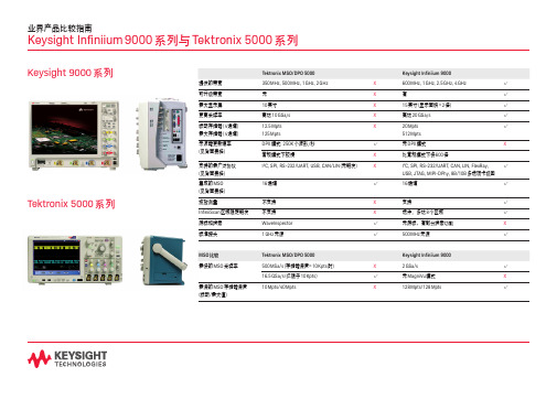
Keysight Infiniium 9000 系列与 Tektronix 5000 系列
Keysight 9000 系列 Tektronix 5000 系列
Tektronix MSO/DPO 5000
提供的带宽
350 MHz, 500 MHz, 1 GHz, 2 GHz
keysight频谱仪的使用方法
文章标题:深度解析Keysight频谱仪的使用方法在现代高科技领域中,频谱仪作为一种重要的测量仪器,在各个领域都有着广泛的应用。
而其中,Keysight频谱仪作为业界领先的产品,其准确性和稳定性备受认可。
在本文中,我们将深入探讨Keysight频谱仪的使用方法,以便读者能更好地掌握这一重要仪器的操作技巧。
一、Keysight频谱仪的基本原理Keysight频谱仪是一种用于测量信号功率随频率的变化情况的仪器。
它通过将输入信号转换为频率域,然后显示其频谱特性,从而帮助工程师分析和解决电磁干扰、无线电接收机灵敏度以及无线电发射机功率等问题。
在实际应用中,Keysight频谱仪可以广泛用于通信、无线电侦察、雷达系统等领域。
二、Keysight频谱仪的使用步骤1. 准备工作:将频谱仪与测试设备连接,并确保设备处于正常工作状态。
2. 设置参数:根据实际测试需求,设置频率范围、RBW(分辨率带宽)、VBW(视频带宽)等参数。
3. 校准仪器:在进行测试之前,需要对频谱仪进行校准,确保测试结果的准确性和可靠性。
4. 进行测试:启动频谱仪,并观察信号频谱特性的显示情况。
5. 分析结果:根据显示结果,分析信号的频谱特性,以达到预期的测试目的。
三、Keysight频谱仪的高级功能除了基本的频谱分析功能之外,Keysight频谱仪还具有许多高级功能,如干扰分析、调制分析、无线电频谱监测等。
这些高级功能为工程师提供了更多的测试手段,使其能够更加深入地分析和解决实际问题。
四、对Keysight频谱仪的个人理解作为一个工程师,我对Keysight频谱仪有着深刻的认识和理解。
在实际工作中,我发现Keysight频谱仪不仅具有高精度和高稳定性的特点,而且其强大的功能使得我能够更全面地了解被测信号的特性,从而更好地进行故障分析和解决。
总结起来,Keysight频谱仪作为一种重要的频谱分析仪器,在现代通信领域具有着不可替代的地位。
通过本文的深入探讨,相信读者对Keysight频谱仪的使用方法和功能特性已经有了更加全面、深刻的理解。
数据采集系统 Keysight DAQ970A DAQ973A 用户指南说明书
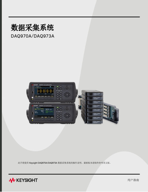
数据采集系统DAQ970A/DAQ973A此手册提供 Keysight DAQ970A/DAQ973A 数据采集系统的操作说明。
最新版本请始终参考英文版。
用户指南声明6版权声明6手册文档号6版本6发布者6软件修订版6担保说明7技术许可7限制性权限声明7废弃电子电气设备(WEEE)7符合性声明8安全和法规信息9安全注意事项9安全符号和法规标记10韩国A类EMC声明11产品法规及合规性12环境条件121仪器简介13仪器概览14前面板概览15仪器信号器16后面板概览17插件模块概览18尺寸图19远程接口配置20 Keysight IO Libraries Suite20 GPIB设置(仅限DAQ973A)20 LAN设置21 LAN服务27设置为默认值27 LAN重置27 Web界面28关于IP地址和点号的详细信息28 USB设置29技术连接详细信息30 LAN配置过程31固件更新33联系是德科技34 2快速入门35准备要使用的仪器36模块线路连接和安装37安装模块37卸载模块39连接电源和I/O电缆40打开仪器40开机自检40关闭仪器40使用内置帮助系统41查看帮助主题列表41查看前面板键的帮助信息422Keysight DAQ970A/DAQ973A用户指南查看仪器信息42调整提手43在机架中安装仪器44 Keysight BenchVue数据采集(DAQ)软件46 BenchVue数据采集(DAQ)软件许可46 3特征与功能47系统概述48数据采集系统概述48信号发送和切换52测量输入54多功能模块58控制输出59前面板菜单参考61 [Scan/Start]键63 [Monitor]菜单64数字65条形仪表66趋势图67直方图68 [Home]菜单70数据采集模式70 Strain offset71 Alarm output73帮助主题73 User settings74 [View]菜单77 Scan模式中的[View]菜单77 DMM Digitize或Digitizer模式中的[View]菜单82电源分析90 [View]菜单状态93 [Channel]菜单94多路复用模块:测量值94多路复用模块:开关模式130 DAQM907A-多功能模块133 DAQM909A-4通道24位数字转换器模块141被计算通道146使用外部仪器扫描151为通道添加标签152 [Interval]菜单153 Scan模式中的[Interval]菜单153 DMM Digitize模式中的[Interval]菜单156 Digitizer模式中的[Interval]菜单159 [Math]菜单163 mX+b标定163 %标定164 dBm标定164 dB标定165 [Copy]菜单166从单个通道复制/粘贴到单个通道(一对一)166从单个通道复制/粘贴到多个通道(一对多)167从多个通道复制/粘贴到多个通道(多对多)168 Keysight DAQ970A/DAQ973A用户指南3[Alarm]菜单169配置多路复用模块上的警报限值169配置多功能模块上的警报限值170警报限值指示171 [Utility]菜单173 Self Test173 Autocal173 Calibrate174 Security175 Admin175 [Module]菜单176 Scan List176 Card Reset177 Module Label177 Relay Cycle178 [Save Recall]菜单179 Manage Files179 Save180 Recall181设置为默认值181 Log to USB182 Save to USB185 Web界面187“Control Instrument”页面188“Configure LAN”页面188“Help”页面189模块概述190 DAQM900A20通道FET多路复用模块191 DAQM901A20通道衔铁式多路复用模块193 DAQM902A16通道舌簧式多路复用模块195 DAQM903A20通道制动器/通用开关模块197 DAQM904A4x8双线矩阵开关199 DAQM905A1:4双射频多路复用(50Ω)模块201 DAQM907A多功能模块203 DAQM908A40通道单端多路复用器206 DAQM909A4通道24位数字转换器模块208 4测量教程211系统电缆和连接212电缆规格212接地技术214屏蔽技术215高电平信号和低电平信号的分隔215系统电缆误差源215测量的基本知识219内部DMM219温度测量220直流电压测量228交流电压测量232电流测量238电阻测量240应变仪测量243 4Keysight DAQ970A/DAQ973A用户指南频率和周期测量246电容测量248数字化测量249电平触发251低电平信号的多路复用和切换252单线(单端)多路复用器252双线多路复用器253四线多路复用器253信号发送和多路复用254多路复用和切换中的误差源254制动器和通用开关256矩阵切换259 RF信号多路复用261多功能模块263数字输入263数字输出264使用外部上拉电阻265驱动外部开关265积算器266积算器误差267模拟输出(DAC)267继电器的使用寿命和预防性维护269Keysight DAQ970A/DAQ973A用户指南5声明声明版权声明©是德科技2019-2022根据美国和国际版权法,未经Keysight Technologies事先允许和书面同意,不得以任何形式或通过任何方式(包括电子存储和检索或翻译为其他国家或地区的语言)复制本手册中的任何内容。
Keysight 4080 Series Parametric Testers说明书

4080 Series Parametric Testers4082A Parametric Test System &4082F Flash Memory Cell Parametric Test SystemIndustry-Standard Parametric Test System over DecadesLeading-edge technologies demand high performance semiconductor devices available at the lower cost of test in high volume manufacturing. Keysight offers the higher throughput and superior measurement performance by 4082A parametric test system with the easiest migration path from 4070 tester including guaranteed 4070/SPECS program compatibilities and data correlations. 4082F flash memory cell parametric test system provides the fast and precise measurements with the built-in semiconductor pulse generator unit (SPGU), cost-effective pulse generator and optional high-frequency switching matrix.Need to Upgradeyour 4070 SeriesTesters? Array If you use 4070 Seriestester without anyservice and supportagreements, you have achance to get back toprofessional service andsupport by upgrading to4080 Series. ContactKeysight to discuss ifyou want to upgradefrom 4070 to 4080Series by reusing someof your systemcomponents with longersupport life.Keysight 4080 Series: Parametric Test System Total SolutionKeysight 4080 Series offers a wide range of measurement capabilities required for fundamental parametric test. You can easily perform DC and capacitance measurements such as Vth, Ids, Idoff, and Cox, to name just a few. 4080 Series supports three types of SMU (Source Monitor Unit) for DC measurement. Several other instruments options, such as a digital voltmeter (DVM), a spectrum analyzer and an LCR meter, provide the enhanced measurement capabilities.Hardware, Software, Accessories, and Professional ServicesYou might think the 4080 Series parametric tester as a hardware integrated system with system cabinet and test head, however, there are more essential system elements of software, accessories, and professional service by Keysight technical experts.Figure 1. Parametric Test System Total Solution4080 Series as Single Offer of Total SolutionKeysight also offers solution support and training as professional services to provide a quickerstart up, maximize your productivity, and minimize downtime of systems. Keysight experts havedeep domain knowledge of test equipment, software, standards, and regulations. Service and solutions from Keysight provide truly trusted systems that you can rely on the measurementsyou make, through the proactively structure an on-site service plan that can include an on-siterepair service, a remote response team, a scheduled calibration services, or timely software updates.•Upfront purchase: configuring available hardware and software options along with some professional Application Engineer (AE) consulting and Customer Engineer (CE) uptimeservice such as installation, repair, and calibration.o Hardware warranty and service agreements are essential for first 12 months and available to extend to 36 months.o Software subscription service is offered for first 36 months as required.•Post-sales: upgrading hardware and software with available retrofit kits and professional AE or CE services. Renewals of service agreement are available with both hardware servicesand software subscription.4080 Series has the test head and system cabinet to use with the probers in semiconductor wafer production line. Most of hardware elements are configurable per your test needs and test structure design to maximize the production capacity and for the highest throughput to archive.4080 Series ModelsChoose from two models for your parametric test requirements.More Hardware Elements to Configure 4080 SeriesThese are also configurable for the test parameters and test structure design of your wafer.4080 Series has the dedicated system controller with Linux operating system (Red Hat Enterprise Linux). This controller has the 4080 system software with fundamental capabilities to operate and control the 4080 test system. The controller can be installed with the optional but essential software such as SPECS and SPECS-FA effective in managing the semiconductor wafer production and factory automation with 4080 Series.Keysight SPECS (Semiconductor Proces Evaluation Core Software)Keysight SPECS is a test shell for Linux-based 4080 Series with code compatibility of test plans and algorithms from 4070 Series. You can minimize the transition cost, utilize existing 4070 codes, and lower the cost of ownership with the latest low-cost Linux environment.Keysight SPECS-FA (Factory Automation)Keysight SPECS-FA, the factory automation version of Keysight SPECS test shell.Figure 2. SPECS-FA operation panelOffline Debug Environment of SPECS & SPECS-FAFor test plan development and debug purpose, offline SPECS and SPECS-FA environment (running without live connection to 4080 Series parametric test system) is available for optional purchase.Virtual Mulitple Testhead (VMT) Technology to Improve Measurement ThroughputAll 4080 Series testers can enable this advanced asynchronous parallel test technology online with a software licensing. This technology allows separate measurement tasks to run independently. Unlike conventional parallel test schemes, no measurement time is ever wasted. As soon as one set of resources finishes making a measurement it can immediately start the next measurement. Net efficiency is like having independent multiple test heads in a single tester and greatly improves measurement throughput.Figure 3. Asynchronous Parallel Test with Keysight VMTAvailable Software OptionsThere are available options for 4080 Series system software, SPECS and SPECS-FA as follows. •Software media on CD-ROM•Paper manuals (English, Japanese)Software with Subscription Service4080 Series system software, SPECS and SPECS-FA have offered 36 months subscription service for each new tester at purchase. When the software media option is purchased, 36-month software media subscription is available.1. Software License-To-Use (LTU) subscription service2. Software media subscription serviceTo maintain the software with the latest enhancements and defect fixes, Keysight recommends renewing the software update subscription with 4080 Series system software, SPECS and SPECS-FA. You can access to the latest software within the subscription service as well as the remote technical support calls to local Keysight AE experts.AccessoriesOptional accessories are available for 4080 Series. All accessories are orderable with 4080 Series and retrofittable as post-sales.They are typically used for specific purpose to make the 4080 Series test system more robust for any unwanted failures or additional features with additional components like adapter and fixture.1 All new 4080 Series includes ESD resistor boxes as mandatory accessories.Keysight Professional ServicesKeysight offers numbers of services to complete the parametric tester solution including;On-site installation servicesThis is a standard service for every new parametric test system at purchase. Keysight Customer Engineer (CE) will install the system at on-site. Before installing the system, Keysight CE also performs site verification as pre-installation process.Warranty and extended services12 months of on-site repair service is offered as a standard warranty. Extended warranty service agreements are also available for sale.Calibration services12 months of on-site calibration service agreement is offered with the parametric test system. Extended calibration service agreements are also available for sale.Productivity assistanceCustomers can choose the term of productivity assistance from a day to required terms Keysight professional Application Engineer (AE) consulting services.Application software supportKeysight AE consulting is also available for specific deliverables such as software customization, software program conversion or software program optimization to assist customers programming for additional test parameters, and/or throughput improvement by optimizing software design.Startup assistanceTo correctly set up the parametric test system and check through all purchased functions to operate as soon as possible, Keysight Customer Engineer (CE) can help your smooth production ramp up with the startup assistance.Training (on-site, Keysight office, or remote)Various trainings are provided by each region or country to meet your local needs. Contact to the training coordinator in your region or country to see what trainings are available and get a quote of the right ones in local price.Post-sales professional serviceKeysight offers all above consulting services for post-sales as well. Feel free to contact Keysight representative if you need additional needs for new operator trainings and/or for tester throughput improvements for lowering cost of test.Post-sales service agreement and contract renewalWhen the initial service agreements of hardware and software subscription are expiring, Keysight contract sales team will propose you for renewals based on your current system configuration. Request your renewal quote to secure and maintain the parametric test system up and running with the minimized downtime.Upgrading Your 4080 Series Parametric Test SystemIn case you want to upgrade 4080 Series hardware elements, you can purchase several retrofit kits and necessary AE/CE consulting service as a customized single order.•Model number: N9170U•Description: Hardware retrofit set for parametric test systemo Includes hardware retrofit kits and professional AE/CE services as solution upgrade packageSolution Upgrade Package Available Retrofit SelectionsHardware elements Pin boards, SMUs, HF matrix & pulse switch, test resources, rackmount kitsAccessories Test fixture adapter, performance check fixture, breakdownprotectorProfessional services AE consulting service with training and softwareCE uptime service and custom solutionsConclusionAll parametric test designers want to improve the throughput and minimize any production downtime for the better cost of test in semiconductor wafer productions. To overcome some typical but difficult process test challenges in your semiconductor wafer production, Keysight offers the total solution on parametric test not only with hardware and software but with professional AE and CE consulting service for your 4080 Series Parametric Test System.If you need any technical consulting service on throughput improvement and/or advice on service agreements to reduce the unwanted downtime, contact Keysight as we offer the various professional service as agreement and per-incident consultation to maximize your productivity and production capacity.Learn more at: For more information on Keysight Technologies’ products, applications, or services,please contact your local Keysight office. The complete list is available at:/find/contactus。
设备固件更新的操作规程
设备固件更新的操作规程一、背景介绍设备固件是指嵌入式系统中的软件程序,它负责管理设备的硬件和操作系统之间的通信和交互。
随着技术的不断发展,设备固件更新成为保证设备性能和安全性的重要步骤。
为了确保设备固件更新的安全性和有效性,制定本操作规程。
二、适用范围本操作规程适用于所有需要进行设备固件更新的情况,包括但不限于以下情况:1. 设备功能升级或修复。
2. 设备固件漏洞修复或安全升级。
3. 设备厂商发布的新固件版本。
三、操作前准备在进行设备固件更新之前,需要进行以下准备工作:1. 确认设备型号和当前固件版本。
2. 从设备厂商官方网站下载最新的固件版本,并确保其兼容设备型号。
3. 准备设备更新所需的连接线缆以及设备供电等条件。
4. 确保设备未处于运行状态,并备份设备重要数据。
四、设备固件更新步骤1. 连接设备将设备与电脑或其他终端设备通过合适的连接线缆相连。
确保连接的稳定性和正确性。
2. 打开固件更新软件运行设备固件更新软件,选择相应的设备型号和当前固件版本。
3. 导入固件文件在固件更新软件中选择“导入固件文件”选项,将下载好的最新固件文件导入到软件中。
4. 进入设备固件更新模式根据设备型号和厂商要求,将设备进入固件更新模式。
这可能需要按下特定的设备按钮或在设备界面中进入设置选项。
5. 开始固件更新在固件更新软件界面上点击“开始更新”按钮,等待固件更新过程完成。
期间不要断开设备与电脑的连接,并确保设备供电正常。
6. 验证固件更新更新完成后,固件更新软件会提示成功或失败。
如果固件更新成功,可以断开设备与电脑的连接,并重新启动设备。
在设备界面确认固件版本已被成功更新。
7. 测试设备功能在设备重新启动后,对设备的功能进行一系列的测试,以确保固件更新后设备的正常运行和功能完整。
五、注意事项1. 在设备固件更新过程中,不要进行其他操作或断开设备与电脑的连接,以免造成固件损坏或设备无法正常启动。
2. 确保从设备厂商官方网站下载的固件版本为最新版本,并与设备型号完全匹配。
Keysight 34972 70A 数据采集单元的最新 Keysight 软件迁移指南说明书
Keysight TechnologiesMigrating to the Latest Keysight Software for the 34972/70A Data Acquisition UnitsMigration GuideKeysight’s BenchVue Data Acquisition (DAQ) Control and Analysis app (BV0006B) is the next-generation software application for users that own Keysight’s 34972A or 34970A data acquisition units. Many of the features that were popular in the BenchLink Data Logger Pro Software (34830A); BenchLink Data Logger 3 software (34825A); or the previous BenchVue DAQ and DAQ Pro version apps (v3.x and below) have been updated and included in the modern BenchVue DAQ app with more features and updates to come. The table on page 3 provides easy reference regarding which features are available, enhanced, and ready for you to use with the new BenchVue DAQ app. Effortlessly, migrate from older DAQ software to the new BenchVue DAQ Control and Analysis app and start driving measurements to actionable insights faster today. BenchVue SoftwareKeysight BenchVue software for the PC eliminates many of the issues around bench testing. By making it simple to connect, control instruments, and automate test sequences you can quickly move past the test development phase and access results faster than ever before. You will derive answers faster by easily viewing, logging and exporting measurement data and screen images with only a few clicks of your mouse. Dedicated instrument apps allow you to quickly configure the most commonly used measurements and setups for each instrument family. BenchVue apps provide extensive data, trace and measurement logging capabilities and automation with Test Flow. BenchVue supports hundreds of Keysight instrument types and models all from one easy to use application. With BenchVue, you get more from your instruments.Test Flow AutomationIncluded with the DAQ app is BenchVue Test Flow which allows you to quickly build automated test sequences, send SCPI commands, and control multiple instruments. Gain deeper access to your instrument’s capabilities with Command Expert sequences integrated into Test Flow. The intuitive interface enables you to quickly create instrument test sequences significantly reducing test development time.Keysight continues to provide enhancements to the BenchVue DAQ app to integrate more Test Flow automatable controls (available late 2017) making it even easier to build test sequences.Keysight Software Features and Enhancements ComparisonsConclusionThe next-generation software for DAQ users is the BenchVue Data Acquisition Control and Analysis app (BV0006B). Most users will be able to replace their older BenchLink Data Logger Pro software with BenchVue’s DAQ app with little effort.The BenchVue DAQ app provides a modern software experience with an intuitive user interface that shortens the learning curve giving you to access your DAQ measurements and data faster, reducing your test and development time.Control, Automate and Simplify with BenchVueLearn more about the BenchVue Data Acquisition Control and Analysis app at/find/BenchVueDAQBenchVue connects to over 470 Keysight instruments and counting. To view the BenchVue supported instruments list visit:/find//BenchVueInstrumentsTo learn more about BenchVue software and its other time-saving apps visit:/find/BenchVueThis information is subject to change without notice.© Keysight Technologies, 2017Published in USA, March 28, 20175992-2223ENmyKeysight/find/mykeysightA personalized view into the information most relevant to you.Keysight Infoline/find/InfolineKeysight’s insight to best in class information management. Free access to your Keysight equipment company reports and e-library.KEYSIGHT SERVICESKeysight Services/find/serviceOur deep offering in design, test, and measurement services deploys an industry-leading array of people, processes, and tools. The result? We help you implement new technologies and engineer improved processes thatlower costs.Three-Year Warranty/find/ThreeYearWarrantyKeysight’s committed to superior product quality and lower total cost of ownership. Keysight is the only test and measurement company withthree-year warranty standard on all instruments, worldwide. And, we provide a one-year warranty on many accessories, calibration devices, systems andcustom products.Keysight Assurance Plans/find/AssurancePlansUp to ten years of protection and no budgetary surprises to ensure your instruments are operating to specification, so you can rely on accurate measurements.Keysight Channel Partners/find/channelpartnersGet the best of both worlds: Keysight’s measurement expertise and product breadth, combined with channel partner convenience.For more information on KeysightTechnologies’ products, applications or services, please contact your local Keysight office. The complete list is available at:/find/contactus Americas Canada (877) 894 4414Brazil 55 11 3351 7010Mexico001 800 254 2440United States (800) 829 4444Asia Pacific Australia 1 800 629 485China800 810 0189Hong Kong 800 938 693India 1 800 11 2626Japan 0120 (421) 345Korea 080 769 0800Malaysia 1 800 888 848Singapore 180****8100Taiwan0800 047 866Other AP Countries (65) 6375 8100Europe & Middle East Austria 0800 001122Belgium 0800 58580Finland 0800 523252France 0805 980333Germany ***********Ireland 1800 832700Israel 1 809 343051Italy800 599100Luxembourg +32 800 58580Netherlands 0800 0233200Russia 8800 5009286Spain 800 000154Sweden 0200 882255Switzerland0800 805353Opt. 1 (DE)Opt. 2 (FR)Opt. 3 (IT)United Kingdom0800 0260637For other unlisted countries:/find/contactus(BP-2-23-17)/go/quality Keysight Technologies, Inc.DEKRA Certified ISO 9001:2015Quality Management SystemEvolvingOur unique combination of hardware, software, support, and people can help you reach your next breakthrough.We are unlocking the future of technology.From Hewlett-Packard to Agilent to Keysight。
keysight breaking point教学 -回复
keysight breaking point教学-回复【Keysight Breaking Point教学】一步一步回答首先,让我们来了解一下Keysight Breaking Point是什么。
Keysight Breaking Point是一种网络负载和性能测试解决方案,它可以模拟现实世界中的网络流量,以评估网络设备和应用程序在高负载条件下的性能稳定性和安全性。
它是Keysight Technologies公司推出的一款强大而全面的网络性能测试工具。
接下来,让我们一步一步来了解如何使用Keysight Breaking Point进行性能测试。
第一步:安装与配置首先,需要安装Keysight Breaking Point软件,确保计算机满足系统要求。
安装完成后,运行软件并进行初始化设置,包括选择测试目标、配置网络适配器等。
此外,还需配置合适的许可证以使用软件的全部功能。
第二步:创建测试拓扑在Keysight Breaking Point中,测试拓扑是描述网络设备和应用程序之间连接和流量路径的图表。
您可以使用软件提供的图形界面工具来创建测试拓扑,将网络设备、虚拟机、应用程序等连接起来,以模拟实际网络环境。
您可以根据实际需要自定义测试拓扑,包括添加和删除设备、连接线路等。
第三步:配置流量和负载一旦测试拓扑创建完成,下一步就是配置流量和负载。
Keysight Breaking Point提供了多种类型的流量模板,例如VoIP、视频流、邮件流量等,可以根据需要选择并配置合适的流量模板。
同时,您还可以定义流量的属性,如协议类型、带宽、延迟等。
此外,您还可以设置负载,模拟大规模用户访问或高频率请求等场景,以评估系统在高负载条件下的性能表现。
第四步:运行测试在配置完流量和负载后,您可以开始运行性能测试了。
在运行测试之前,建议先进行一些预测试操作,如验证网络设备的连接、检查参数设置是否正确等。
然后,点击运行按钮,软件会开始模拟流量并产生测试结果。
是德科技 KeysightCare 服务和升级
1.客户需签署是德科技软件协议方可享受软件支持。
2.所有提供的服务均受国家或地区实际条件以及法律条款与条件的限制。
3.KeysightCare Assured 第一年支持在指定产品中提供。
联系我们:页 2KeysightCare 提供远超出基本保修范围的全面客户服务,包括以下关键特性:•您可以通过 KeysightCare 门户网站直接在线创建和管理案例,搜索知识库寻找问题答案,设置通知以接收最新的软件和固化软件更新。
•您还可以访问KeysightCare 知识中心,轻松获得培训资源。
知识库是一个即时更新且具有搜索功能的数据库,其中的内容安排得井井有条,可以让您更快地找到问题的解决方案。
•针对在工作时间之外有关键任务需求的客户,我们提供24x5 技术支持。
•针对有复杂应用的客户,我们提供现场技术支持,以确保您的团队正常运行。
•通过 KeysightCare,还可以接收关于最新软件和固件更新的主动通知。
在软件方面,最新的修补程序、更新和增强版本可确保您的团队即时了解最新的技术和标准。
•客户支持经理是您所有支持请求的单一上报点。
您可以获得指定支持团队的服务,他们了解您的确切测试配置,并能快速为您提供所需支持。
如需了解关于 KeysightCare 的更多信息,请访问我们的网站/find/keysightcare如欲了解更多信息,请访问:如需了解关于是德科技产品、应用和服务的更多信息,请与是德科技联系。
如需完整的联系方式,请访问:/find/contactus联系我们:本文中的信息可不经通知而更改。
© Keysight Technologies, 2018, Published in USA, December 19, 2018, 5992-3535CHCN。
了解Keysight翻新产品和程序
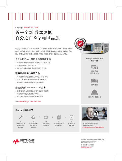
近乎全新 成本更低 百分之百 Keysight 品质
Keysight Premium Used 为您提供了大量精选的高品质测试设备。每台设备都会 经过严格的翻新流程,经过翻新,各设备的性能指标和外观都能达到新机的标 准。您可以以更少的成本获得具有百分之百质量和性能的 Keysight 产品。
01 根据您的订单 检查并重新 组装仪表
02 将固化软件和 软件升级为 最新版本
03 校准和验证 安全性能
04 添加原版说明书 和配套附件
05 执行 101 点 最终检验
请让我们带领您体验业界 最全面的翻新程序 /find/refurbished
本文中的产品指标和说明可不经通知而更改 ©Keysight Technologies, 2014 出版号: 5990-6609CHCN 原出版日期: 2013 年 4 月 新出版日期: 2014 年 9 月
近乎全新产品一样的保修服务和ቤተ መጻሕፍቲ ባይዱ持
– 与新产品享受同样的 3 年保修期, 可扩展为 5 年 – 可选择 3 或 5 年的校准计划 – Keysight 及其授权合作伙伴提供个人支持
Keysight Premium Used 核心价值
获得更多物美价廉的产品
– 与完全购买新仪器相比, 成本至少节省 20% – 可添加软硬件, 享受同样的成本节省方式 – 提供标准的配套附件和完全校准服务
成本节省 20% 到 50%
全面翻新
查找到您的 Premium Used 交易
– 浏览我们符合您预算的型号产品的当前库存 – 指定您需要的选项并提交申请 – 我们将在 3 到 5 个工作日内与您联系 访问 /find/used 标准的 3 年保修期
英倍特系统更新详细步骤(前三步都为Jitag方式)
下面将完整的介绍实验系统vivi、Linux内核、ramdisk根文件系统、 yaffs根文件系统映像的固化过程(在实验系统出厂前已经固化好出厂Linux映像,下面的内容仅供参考,用户如果并不需要更新全部映像,可以单独更新单个映像)1. 固化vivi● 准备工作:1)准备好EduKit-IV 实验平台一套,Mini2410-IV 核心子板一套,5V/2A 电源适配器一个,EasyICE烧写器一个,交叉串口线一个。
并口线1 个,U 盘一个(空闲空间大于32M)。
2)在测试台摆放好EduKit-IV 实验平台,小心打开EduKit-IV 实验平台上盖,注意防止箱体向后倾倒(最好箱体上盖后面靠着其他物品)。
3)检查EduKit-IV 实验平台出厂跳线,注意Mini2410-IV 核心子板上的跳线为闭合状态,电源拨动开关拨向向下端的断开状态。
4)连接5V/2A 电源适配器到EduKit-IV 实验平台的电源接口(电源插座供电为220V 市电)。
5)连接EasyICE 烧写器:JTAG 线连接到EduKit-IV 实验平台的Area1 区的ARM JTAG 接口,并口端通过并口线连接PC 机与EasyICE 烧写器。
(用于固化Bootloader)6)连接交叉串口线于PC 机的串口端和EduKit-IV 实验平台的COM2 端。
7)将Mini2410-IV 核心子板插入EduKit-IV 实验平台的CPU PACK 接口,注意用力均匀且确保插槽连接紧密(一般可用力先插紧上面的槽,然后在插紧下面的槽,插好后,再均匀用力固定确保连接紧密,槽插进去的时候可以听到卡进去的声音)。
8)将EduKit-IV 实验平台的电源的拨动开关拨向向上端的加电状态,给实验平台上电。
可以看到POWER 区的三个红色电源指示灯会亮:1V8_LED、3V3_LED、5V0_LED。
如果有任意电源指示灯不亮,请立刻关闭电源,检查电路故障。
是德科技推出全新技术更新服务方案

是德科技推出全新技术更新服务方案
佚名
【期刊名称】《国外电子测量技术》
【年(卷),期】2016(0)4
【摘要】2016年4月21日,是德科技公司(Keysight TechnologiesInc.)宣布推出全新的技术延伸与整合服务,旨在帮助客户最大程度的提高测试仪表资产价值并实现最大利用率。
是德科技的技术更新服务(TechnologyRefresh Service)方案让客户能够充分利用有限的经费,轻松地获得最新测试技术服务。
【总页数】2页(P107-108)
【关键词】技术服务;技术更新;资产价值;利用率;科技;仪器;测试仪表;客户
【正文语种】中文
【中图分类】F275.2
【相关文献】
1.爱迪德公司推出业内首张按时计费智能卡全新创收技术助Technocell实现收费内容的最大投资回报/SureWest在新建IP视频网络中选用爱迪德技术/城市热点推出NETC网络管理监控系统 [J],
2.朗讯科技全新推出基于服务智能网络的IP策略协助服务供应商提供真正具备盈利能力及商业质量的IP服务/飞利浦半导体与Stonestreet One组成策略性联盟携手提供蓝牙技术解决方案 [J],
3.是德科技引领5G技术发展,推出全新5G信道探测参考解决方案 [J],
4.是德科技推出EMI接收机更新方案及5G EMC测试方案 [J],
5.是德科技推出全新参考解决方案,加速卫星信号的监测和验证 [J],
因版权原因,仅展示原文概要,查看原文内容请购买。
KeysightPathWaveADS2023软件下载分享

KeysightPathWaveADS2023软件下载分享2022年7月6日,是德科技推出了ADS的年度更新版本Keysight PathWave ADS 2023,为电路设计人员提供了增强的电磁(EM)仿真功能。
PathWave ADS 2023 继续提供业界最完整的射频和微波、高速数字和电力电子设计功能仿真软件,ADS 2023版本提供了新的和增强的功能,以提高射频和微波电路和系统设计人员的生产力和可用性。
下边关于ADS 2023版本的更新亮点老wu 摘录于是德科技官网,更多关于 ADS 2023 的版本更新亮点请访问是德科技的官网链接:/us/en/lib/resources/software-releases/pathwave-advanced-design-system-ads-2023.html电路仿真的增强•简化的远程和分布式仿真管理,支持基于云的高性能计算(HPC)。
•新的Leti-UTSOI 102.6晶体管模型用于精确的模拟和射频电路设计•蒙特卡洛统计控制器现在包括产量优化电热仿真的增强•即使布局和原理图层次不匹配,也支持定制的多技术电热(ETH)流程•PathWave ADS提供业界最精确的电热仿真,可预测有害的瞬态温度峰值的位置和时间,以便在硬件生产前将其修复。
•PathWave ADS的电热动态模型生成器使瞬态电热仿真的速度通常提高了10倍,最高可达100倍,以确保关键任务和关键声誉设计的热可靠性。
高性能计算(HPC)•通过并行的高性能计算(HPC)对电磁和电路仿真进行加速,具有成本效益的、强大的、大容量的基于云的硬件资源,使典型速度提高5倍至20倍•并行化EM simulation (RFPro) 参数扫描•即使是5倍的速度,这也意味着在5天的工作周中可以节省4天的时间,使更多的仿真设计出高性能的、对容错不敏感的射频/微波元件,并大大缩短上市时间高速数字(HSD)设计•内存设计器•支持HBM3, LPDDR5x, IBIS – EMD模型•IBIS 7.1解析器与自定义IBIS文件查看器•多段式智能总线导线连接•Drag-n-drop multi-plots from Expression Manager•改进的CA/数据总线预布局构建器编辑•基于云的高性能计算(HPC)SerDes设计•新的以太网AMI模型器•用于NZR调制和扩频时钟(SSC)的USB AMI模型•USB参考通道模型•用于第6代的PCIe AMI模型生成,带有PAM4调制、DFE抽头和6-lance带串扰的参考通道•通道模拟器中用于Tx的PAM6调制•用于瞬态PAM4模拟的SmartEye探针•增加了3.4和3.7版本的信道操作裕度(COM)。
- 1、下载文档前请自行甄别文档内容的完整性,平台不提供额外的编辑、内容补充、找答案等附加服务。
- 2、"仅部分预览"的文档,不可在线预览部分如存在完整性等问题,可反馈申请退款(可完整预览的文档不适用该条件!)。
- 3、如文档侵犯您的权益,请联系客服反馈,我们会尽快为您处理(人工客服工作时间:9:00-18:30)。
立即与专家联系。 /find/services
本文中的产品指标和说明可不经通知而更改
© Keysight Technologies, 2017 Published in USA, April 26, 2017 出版号:5992-2306CHCN
您需要正确了解目前的测试需求, 同时尝试 预测未来 18 至 24 个月的测试需求。 您的现 有测试系统是否满足这些需求? 如果满足, 请继续使用您的测试设备。 这可以让您的现 有测试系统获得最大投资回报率。 如果您的测试设备不能满足您未来 18 至 24 个月的测试需求, 那么确定哪些测试资产 能够升级或需要替换。
测量能力
购买新的测试设备的客户通常可以分为三 类。 一类购买了太多功能, 为特定需求支付 了过多费用。 另一类则购买了太少功能, 需 要分配更多资金去升级其系统或通过以旧 换新方式获得功能更强大的设备。 第三类购 买了数量正 好的功能, 测量精确度也能满 足独特需求, 因此 这类 客户能够紧跟 技 术 发展的脚步, 同时最大限度节省资本和运营 支出。 您如何优化测试资产的投资回报率?您需要 重新审视您的测试设备并列出详细的清单, 包括采购日期、 保修信息、 校准日程表和测 量能力。 这些资产多久使用一次? 资产闲置 时间占比是否合理?
测量能力
代码兼容性
物理外形
用户界面
种方式在新的测试设备上执行, 这可能导致 错误的或误导性的结果, 从而严重影响吞吐 量、 一致性和盈利能力
了解更多信息: /find/techrefresh
技术更新的四个关键成功要素
物理外形
新仪器是否需要装入现有机架?您测试区 域的占地空间是否有限或被重新分配?您需 要有效评估测试区域的物理环境, 确保您的 新设备能够装入您的测试机架或您预留的 安置空间。 我们的技术更新顾问能够帮助您设计技术 更新计划, 以最大限度提升您的投资回报率 并减少意外停机和中断。 是德科技更新顾问将为您提供以下支持: – 分析您当前的测试需求和测试资产 – 确认能够达到您的测量目标且能获 得最大投资回报的测试资产 – 分析现有持续的维护和校准成本 – – 确认提高能效或减少运营成本的机 会 – 进行测试资产分类, 从而进行升级、 替换、 出售或废弃 – 充分利用信贷 (credit) 、 折扣和促销来 帮助您减少资本开支 (CAPEX) – 利用保修和续保服务来 减 少年度维护 成本 – 制定有效且经济高效的技术更新时 间表
是德科技 技术更新服务
技术更新的四个关键成功要素
制定全面、 经济高效的技术更新策略
更新、 更快、 更好的技术总是层出不穷。 如果您想要最大限度提高投, 那么您需要一个全面、 经济高效的技术更新策略。 获得最大投资回 报的关键就是制定一个能够同时具有以下 4 大要素的技术更新计划: 测量能力、 代码兼容性、 物理外形和您的测试执行流程。
您的技术更新策略
是德科技提供了一系列技术更新服务组合, 通过扩展您现有测试设备的能力或帮助您 经济高效地迁移至更新技术, 让您最大限度 提升测试资产价值。 这些服务包括: 升级现 有设备、 针对旧有资产的扩展服务计划、 多 厂商以旧换新计划 (为旧资产提供极具吸引 力的以旧换新服务) 、 加速技术迁移的专业 协助, 以及相关培训以帮助您更顺利地利用 新测试解决方案。
一个测试系统可能对 您 来说更新、测试 速 度更快、 体积更小、 测量更精确, 甚至操作 更简单, 但是这并不能构成您购买这个系统 的理由。 如果新的测试解决方案不能以要求 的精度执行您所需要的基础测量, 那么上述 这些优势就无所谓了。
代码兼容性
很多仪器供应商声称其新的测试仪器和系 统能够与您的现有测试项目后向兼容。 您需 要阅读详细条文并仔细评估这些声明。 很多 公司只是简单地将现有命令转移至其新的 测试设备中。 这意味着即使您购买了更快、 更精确的一流 测试设备, 您也无法充分利用这些新功能。 新的测试设备与您的旧测试设备并无二致, 因为旧的测试代码限制了新设备的发挥。 还有一种情况是, 您的旧测试代码无法以同
是德科技服务提供从仪器采购、 集成、 优化到更新换代的全套服 务, 贯穿您的仪器的整个生命周期。 我们全面的服务产品能够帮助 您最大限度提升资产利用率, 简化工程操作并降低风险。 – – – – 一站式校准 维修 资产管理 技术更新 – 咨询 – 培训 – 产品购买替代方案
简化您的测试执行流程
您的新设备是否在前后面板有正确的连接? 如果没有, 那么通常会有一个变通的方案来 避免意外情况和部署延期。
