SC-PG中文说明书_TEX48203-699A
德马格中文操作说明书
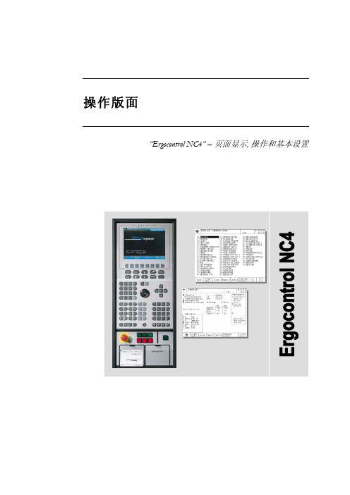
液压顶出 后退 / 前进
气阀 1-4 打开
中子 抽芯 / 进芯
自动安全门 打开 / 关闭
Rotary table index bolt move in / move out
模厚调整 增加 / 减小
旋转模板 逆时针 /顺时针
提示 “模厚调整”按钮只针对曲轴式机床。“自动安全门”和“气阀 1-4”按钮只有当这些功 能配置以后才起作用。“Rotary table latches”, Rotary table index bolt” and “旋转模板”应 用于带转转模板的多色注塑 。
Sfu服EnRc务tVio页InC面Egr功oup 能组
Afu报LnAc警tRio功Mn能Sgr组oup
Fig. 2: 功能选择键
1.2 手动功能键
在手动和点动模式下可通过下面的按钮(见Fig. 3 和 Fig. 4)进行相应的操作。 Fig. 3: 手动模具装置功能
模具 打开 / 闭合
Rotary table latches move in / move out
4.4
帮助功能键和专家系统 .......................................................................................................19
5
频幕 ..........................................................................................................20
Pfu程RnOc序tGio功Rn能AgrM组oSup
Process 过Pfu程RnOc控tCio制EnS功gSr能oCu组pONTROL
恒温火器产品说明书

564 TV GSR2 35K Gas Fireplace -D istributorNOTE: FAN & GS2 WIRELESS WALL MOUNT REMOTE PRE-INSTALLED STEP #2 - ADD AN OPTIONAL FIREBACKNotable ExtrasCommon Brick/HerringboneHandmade BrickFPX Old World Stucco564 TV GSR2 35K Gas Fireplac e - DistributorSTEP #4 - ADD YOUR VENTINGPower Vent Exhaust KitIncludes 3.9" pipe, 90° elbow,high wind horizontal cap.Minimum Vent Section,Rear Vent Flue AdapterVertrical Termination onlyMinimum Horiz Vent Kit E, 8"Includes 90 deg elbow, 3.9" pipe, 12" pipe, (2) 6" pipe, high wind horiz. CapNOTE: ADDITIONAL PIPE SECTIONS MAY BE NEEDED TO MEET THE REQUIREMENTS FOR A SPECIFIC APPLIANCE. REFER TO THE 36" CoolSmart TV Wall™ Kit564 TV 35K Clean Face GSR2 Gas Fireplac e - DistributorNOTE: FAN & GS2 WIRELESS WALL MOUNT REMOTE PRE-INSTALLEDREQUIRED FORPROPANE CONVERSION!STEP #1 - SELECT A LOG SETSTEP #2 - ADD AN OPTIONAL FIREBACKNotable ExtrasCommon Brick/HerringboneHandmade Brick FPX Old World Stucco564 TV 35K Clean Face GSR2 Gas Fireplac e - DistributorSTEP #4 - VENTINGPower Vent Exhaust KitIncludes 3.9" pipe, 90° elbow,high wind horizontal cap.Minimum Vent Kit H, 36" CoolSmart TV Wall™ KitNOTE: ADDITIONAL PIPE SECTIONS MAY BE NEEDED TO MEET THE REQUIREMENTS FOR A SPECIFIC APPLIANCE. REFER TO THE Vent Section,Rear Vent Minimum Horiz Vent Kit E, 8"Includes 90 deg elbow, 3.9" pipe, 12" pipe, (2) 6" pipe, high wind horiz. CapFlue AdapterVertrical Termination only。
西盟冻干机用户手册及说明
冻干机系列用户手册,版本1.0不阅读,不理解,没有遵循手册中的说明,机器会受损,操作人员会受伤并且机器的运转效果受影响目录1. 型号的尺寸1.1. FD5505——FD55251.2. FD5505s—— FD5525s1.3. MCFD5505——MCFD55251.4. SF0020——SF00101.5. TD5070A——TD5070RPS1.6. TFD55051.7. 尺寸2. 安装2.1. 安装的地点2.2. 安装的程序3. 电源和接地线3.1. 电源3.2. 接地线4. 部件和功能的参数4.1 FD5505-FD5525 的部件的参数4.2 控制面板和及其功能的参数5. 操作流程5.1. 手动模式5.2. 自动模式5.3. 预冷装置的操作5.3.1. 控制面板和及其功能的参数5.3.2. 预冷装置的操作流程6. 附件6.1. 真空泵6.1.1. 部件的参数(型号:VP8951,VP8920)6.1.2. 换油频率和如何换油6.1.3. 如何换排气过滤器的元件和换的周期6.2. 干燥腔室6.2.1. 干燥腔室部件的参数6.2.2. 如何连接各附件6.3. 密封焊枪6.3.1. 部件的参数6.3.2. 操作7. 冻干机的一般操作8. 维修服务8.1. 故障检修服务8.2. 维修服务登记8.3. 制冷简图8.4. 真空循环图8.5. 电子示意图8.6. 控制面板的电子示意图9. 保修1. 型号的尺寸1.7. 尺寸2. 安装2.1. 安装的地点1. 置于背光处2. 空气流通好3. 避免过多的灰尘4. 避免机械震动或摇动5. 工作温度:+5℃ to +33℃6. 工作高度:2.000m 以下7. 工作湿度:80%以下(倘若当工作温度达到最大值+33℃,湿度可以是低于57%)8. 电压可变的范围:低于+/- 10%*如果您在上述提到的场合下安装机器,机器不能正常运转。
2.2 安装程序1. 机器的后部和墙应保持30cm或更远的距离2. 在平稳的地方安装3. 滑地板要用螺丝钉固定4. 通风要流畅3. 电源和接地线3.1. 电源1. 确定连接是否安全,插头是否插入电源插座。
Schneider Electric TM3XHSC202 G 电源单元用户指南说明书
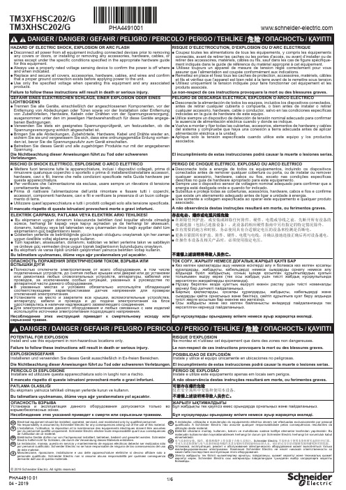
TM3XFHSC202/GPHA449100161012345670123456789HSC202G00 BHSC20200ADigital inputs / Entrées numériques / Digitaleingänge / Entradas digitales / Ingressi digitali / Entradas digitais Dijital giri şler / 数字量输入 / Цифровые входы / Сандық кірістерEncoder / c 24 V* Type T fuse / Fusible de type T / Sicherung Typ T / Fusible tipo T / Fusibile tipo / Tipo de fusível T / T tipi sigorta / T 型熔断器 / Плавкий предохранитель типа ТT түріне жататын сақтандырғыш.**Refer to the encoder documentation for fuse sizing / Pour le calibrage des fusibles, consultez la documentation de l'encodeur / Halten Sie sich zur Dimensionierung der Sicherungen an die Informationen in der Geberdokumentation / Consulte la documentación del codificador para dimensionar los fusibles / Per il dimensionamento del fusibile, consultare la documentazione dell'encoder / Consulte a documentação do codificador para saber o tamanho dos fusíveis / Sigorta boyutlandırma için kodlayıcı dokümantasyonuna bakın / 请参阅编码器文档,了解有关保险丝尺寸调整的信息。
Benchmark Scientific BactiZapper 无线红外灭菌器操作手册说明书

2
3.3) The red indicator light will come on when the toggle switch is in the “High” position. Twenty minutes after the BactiCinerator Sterilizer is plugged in and the switch is in the “high’ position, the optimum sterilizing temperature (825°C) will be reached. If the unit is not going to be used for extended periods of time, please set the power switch in “Off” position to conserve the life of the heater element.
250V 3A 5X20mm
Operating temperature Dimensions(W×D×H) Net Weight
5Ԩ ~ 40Ԩ
4 x 5 x 7 in. 102mm×130mm×180mm 2.9 lbs. / 1.3kg
3.) Operating Instructions
3.1) Remove the BactiZapper from all packaging and place on flat surface.
Contents
Schurter PG20 电路保护器数据手册说明书
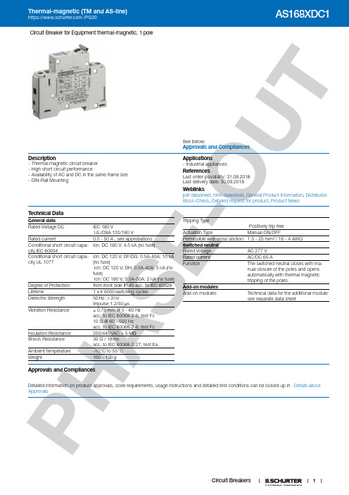
1P HA SE -O UTCircuit Breaker for Equipment thermal-magnetic, 1 poleSee below:Approvals and Compliances Description- Thermal-magnetic circuit breaker - High short circuit performance- Availability of AC and DC in the same frame size - DIN-Rail MountingApplications - Industrial appliancesReferences Last order possibility: 31.08.2018Last delivery date: 30.09.2018Weblinkspdf datasheet , html-datasheet , General Product Information , Distributor-Stock-Check , Detailed request for product , Product NewsT echnical DataGeneral data Rated Voltage DCIEC 180 VUL/CSA 120/180 VRated current 0.5 - 50 A , see approbations Conditional short circuit capa-city IEC 60934Icn: DC 180 V: 4.5 kA (no fuse) Conditional short circuit capa-city UL 1077Icn: DC 120 V; DF/DG: 0.5A-40A: 10 kA (no fuse)Icn: DC 120 V; DH: 0.5A-40A: 5 kA (no fuse)Icn: DC 180 V; 0.5A-50A: 2 kA (no fuse)Degree of Protection from front side IP 40 acc. to IEC 60529Lifetime 1 x Ir 6000 switching cycles Dielectric Strength 50 Hz: > 2 kVImpulse 1.2/50 μsVibration Resistance ± 0.75 mm @ 5 - 60 Hzacc. to IEC 60068-2-6, test Fc 10 G @ 60 - 500 Hzacc. to IEC 60068-2-6, test FcInsulation Resistance 250/440 VAC > 5 M ΩShock Resistance 30 G / 18 msacc. to IEC 60068-2-27, test EaAmbient temperature -10 °C to 55 °C Weight 100 - 130 gTripping TypePositively trip freeActuation Type Manual ON/OFFPermissible wire cross section 1.5 - 25 mm² / 16 - 4 AWG Switched neutral Rated Voltage AC 277 V Rated current AC/DC 65 A Function The switched neutral closes with ma-nual closure of the poles and opensautomatically with thermal magnetic tripping of the poles.Add-on modules Add-on modules Technical data for the additional modulesee separate data sheetApprovals and CompliancesDetailed information on product approvals, code requirements, usage instructions and detailed test conditions can be looked up in Details about Approvals2P HA SE -O U TApprovalsThe approval mark is used by the testing authorities to certify compliance with the safety requirements placed on electronic products. Approval Reference T ype: AS168XApproval LogoCertificates Certification Body DescriptionVDE Approvals VDEVDE Certificate Number: 40005743UL Approvals UL UL File Number: E216629 / E71572UL Approvals ULUL File Number: E216629 / E71572CQC ApprovalsCQCCCC Certificate Number: 2013010307594187Product standardsProduct standards that are referencedOrganizationDesignStandardDescriptionDesigned according to IEC 60934Circuit-breakers for equipment (CBE)Designed according to UL 1077Standard for Supplementary Protectors for Use in Electrical Equipment Designed according toCSA C22.2Supplementary Protectors Application standardsApplication standards where the product can be usedOrganizationDesignStandardDescriptionDesigned for applications acc.IEC/UL 60950IEC 60950-1 includes the basic requirements for the safety of information technologyequipment.CompliancesThe product complies with following Guide LinesIdentificationDetailsInitiatorDescriptionCE declaration of conformitySCHURTER AG The CE marking declares that the product complies with the applicable requirements laid down in the harmonisation of Community legislation onits affixing in accordance with EU Regulation 765/2008.RoHSSCHURTER AGEU Directive RoHS 2011/65/EUChina RoHS SCHURTER AG The law SJ / T 11363-2006 (China RoHS) has been in force since 1 March2007. It is similar to the EU directive RoHS.REACHSCHURTER AGOn 1 June 2007, Regulation (EC) No 1907/2006 on the Registration, Evaluation, Authorization and Restriction of Chemicals 1 (abbreviated as "REACH") entered into force.PDimension [mm]AS168X 1 poleA) 35 mm DIN rail EN 50022B) Max. torqueWire crosssection Max. torque1.5 ... 10 mm22.5 Nm16 ... 25 mm2 3.1 NmAWG #16 ... 8 20 ... 22 lb–inAWG #6 ... 4 26 ... 28 lb–inAS168X 1 pole and switched neutral poleA) 35 mm DIN rail EN 50022B) Max. torqueWire crosssection Max. torque1.5 ... 10 mm22.5 Nm16 ... 25 mm2 3.1 NmAWG #16 ... 8 20 ... 22 lb–inAWG #6 ... 4 26 ... 28 lb–in34PHS-U Diagrams AS168X-CB1...AS168X-CB1...NAS168X-CB1... / AS168X-ACBH1AS168X-CB1... / AS168X-ACBH2AS168X-CB1... / AS168X-ACBS1AS168X-CB1... / AS168X-ACBS2AS168X-CB1... / AS168X-ACBA5P-U Effect of ambient temperatureAC-breaker are calibrated for an ambient temperature of +40°C, DC-breakers for +23°C. To determine the rated current for a lower or Time-Current-Curves Version DF / Magnetic 4.5-8 xl nT i m e i n S e c o n d snMultiple of Rated Current InReference Temperature +23°Version DG / Magnetic 9-16 xl nT i m e i n S e c o n d snMultiple of Rated Current InReference Temperature +23°6A-O U TVersion DH / Magnetic 18-32 xl nT i m e i n S e c o n d sn0,1ms1ms10ms0,1s1s10s100sMultiple of Rated Current InReference Temperature +23°Config. CodeAS168X-CB 1DG |200|N |The characters are placeholders for the correspondingly keys of selections from the key tables.AS168X-CB 1 DG |200|N | = Number of PolesAS168X-CB |1| DG |200|N | = Tripping characteristicsAS168X-CB |1|DG | 200 |N | = Rated currentAS168X-CB |1|DG |200| N | = Switched neutral7P HA SE -O U VariantsPackaging Unit 1 PcsThe specifications, descriptions and illustrations indicated in this document are based on currentinformation. All content is subject to modifications and amendments. Information furnished is believed 19.02.2018。
普特单钩秤仪表说明书 (1)

****单钩秤仪表使用说明书承德普特智能电子有限公司目录第一章仪表简介一、概述 (2)二、技术性能 (2)第二章接口定义一、接口定义 (3)二、串行通讯协议 (4)第三章标定调试一、参数设置 (7)二、重量标定 (9)三、补偿标定 (10)四、修改标率和标定调试密码 (10)第四章操作使用一、指示灯说明 (11)二、开机置零和按键置零 (11)三、测试 (11)四、超载报警功能 (11)五、自动置零功能 (11)六、信息提示 (11)第五章维护保养及注意事项一、使用 (12)二、维护 (12)警告:请认真阅读本使用说明书后才能使用本仪表,如有不明白之处请先联系我公司,了解清楚后再使用本仪表。
谢谢合作,欢迎使用我公司产品。
第一章仪表简介一、概述******单钩秤仪表由高速高精度A/D转换器和单片计算机组成,经过特殊的数字滤波技术能快速稳定读数。
******单钩秤仪表标定、操作使用均非常方便。
所有电子元件均使用工业级元件,确保在恶劣环境下能正常工作。
二、技术性能⑴输入信号范围:-5~+15mV⑵A/D转换:24位Sigma-Delta 模数转换⑶非线性:≤0.0015﹪F.S.⑷最小分辨率:0.1uV/d⑸供桥电压:10V/300mA(可接8个350Ω传感器)⑹传感器接口:带长线补偿的六线制传感器接口⑺串行通讯接口:RS232C和RS485接口,波特率可选⑻大屏幕接口:电流环接口⑼开关量接口:超载报警继电器输出⑽显示屏:6位0.8英寸超高亮LED显示器⑾指示灯:预警、延时报警和报警指示灯⑿供电电源:AC220V、50Hz⒀工作温度:-40~+85℃⒁相对湿度:≤90﹪R.H⒂外形尺寸:210×230×80 mm⒃重量: 2.3kg一、接口定义1、传感器接口(采用DB-9芯孔连接器)注:在采用四线制传感器时,1、2脚必须短接,4、5脚必须短接2、串行通讯接口注:20mA电流环接口用于接大屏幕显示器,波特率为4800bps。
得康充电器使用说明书电池、充电器及充电技术中国电动车联盟论坛
得康充电器使用说明书电池、充电器及充电技术中国电动车联盟论坛买了得康充电器弄了1天还是不知道怎么玩,,找卖家给我弄个详细的说明书我现在复制1下供大家参考:德康便携式智能充电器BDC01A(第二代)使用手册杭州德康蓄电池修复仪有限公司产品概述感谢您选择得康超级充电器升级版BDC01A。
得康充电器BDC01,是一款经受四年高端用户苛刻测试的高性能的电动车智能脉冲充电器,在中国电动车充电器领域久负盛名,产品远销日本,韩国,德国,巴西,澳大利亚,印度,港澳台等国家和地区。
应很多充电器发烧友的强烈要求,得康公司推出了得康的升级版本BDC01A。
本产品采用二块工业控制用单片机构建稳定的核心处理电路,性能可靠,控制精准,自动识别电池组极性,自动匹配与容量适应的充电电流。
完美的实现了人机对话功能,让充电可视化成为现实。
功能特点1、显示电压电流容量。
2、最强充电模式。
0.标准充电模式;A.快速充电模式;B.维护保养充电模式;C.8.33KHz脉冲维修模式;D.过充电模式。
3、可以同时充36V、48V、60V和72V电池组。
4、自由设置充电参数。
简明教程1、容量设置。
通电,不接入电池组,按“容量选择”按键进入容量设置界面。
显示AH.10。
通过按“+”、“-”键选择与充电电池对应的容量,按确定键保存。
2、充电模式。
在没有充电之前,按“充电模式”按键,选择需要的充电模式。
0为正常充电、A为快速充电模式、B为维护保养充电、C为8.33KHZ 脉冲维护、D为过充电。
特别注意:B、C、D模式为比较专业的玩家级别的模式,无停止条件,在这些模式下,用户须对电池与电池充放电理论有一定的了解。
3、专业模式。
在没有充电之前,按“充电模式”按键,选择C充电模式,然后按5下“查询”键进入专业模式。
按“确定”键切换不同的参数。
最后一个参数按“确定”键,保存之前设置的值并退出专业模式。
参数详解。
高手专用,建议新手不要修改出厂默认参数。
AH:电池容量。
太阳能电池分选机使用说明书
⑧1.3.1 连接串口线(串口线)(采集卡线 1米)(电路板连接方式)(电脑主机线)(设备电源线)(脚踏) (设备外接线)点击桌面“(软件主界面——充电前)改光为(软件主界面)种模式切换。
(IV-PV曲线)(原始曲线)2.2当前测试数据区、状态区:点击“给电容充电”后,控制面板上的电压会升到设定值,“当前充电电容状态”则会由红灯转变成绿灯。
设置生产过程中的常用选项。
3.1.1电池规格选择:选择当前的待测电池规格,点击确定后生效。
4. 数据查询介绍数据查询面板可检索指定时间的检测记录。
4.2.2打印和导出数据即可。
5.4生产信息5.4.1生产信息:可输入操作员的名称及设备编号。
5.4.2自动产生:按照在“快速设置”里设置的“测试序列号自动递增。
5.4.3条码产生:选择条码产生后会在主界面上显示一个条码输入的文本框,通过扫码枪或手动输入可将该条码设置为序列号。
选中上图中的“DAQPilot”后,会出现下图所示的界面继续点击“Next”按钮,会出现下图所示的界面继续点击“Next”按钮,会出现下图所示的界面点击上图所示“Install”按钮,开始安装,安装完毕前会出现下图所示的界面点击“Finish”按钮,完成安装。
选择上图中“Driver Installation”选项后,会出现如下图所示的界选择上图中的“Win98/NT/2000/XP/Vista Driver(D2K-DASK)”选选中上图中的“Typical”选项后,然后点击上图中的“Next”,会出现点击上图中的“Install”按钮,会出现如下图所示的界面:点击上图中“Finish”按钮,会出现如下图所示的界面:点击上图中的“EXIT”按钮,退出改安装软件。
然后选择我的电脑,鼠标文件路劲选择到上图中的“inf”文件夹,然后点击“确定”按钮,出现如点击上图中的“完成”按钮,驱动安装完成。
最好还是再在“设备管理器”点击Next按钮勾选,并点击Next按钮选择Custom按钮如图所示选择安装选项,选择MySqlServer选项,点击Browse设定程序安Server data files选项,点击Browse设定程序安装目录和数据文选择Install安装完毕后,选择Next选择Standard Configuration,点击Nextroot 设置密码为 root,点击Next点击Execute进行配置和启动数据库服务数据库启动成功,点击Finish退出。
SC-920 使用说明书 (中文)
目录
!. 规格.............................................................................................................................................. 1 @. 安装.............................................................................................................................................. 1
1. 往机台上的安装. ..............................................................................................................................................................................2 2. 控制盘的安装...................................................................................................................................................................................3 3. 电缆线的连接方法. .........................................................................................................................................................................4 4. 连结杆的安装方法. .........................................................................................................................................................................8 5. 机头的设定方法. ..............................................................................................................................................................................9 6. 机头调整 ( 仅限直接驱动马达方式的缝纫机 ). ............................................................................................................... 10
斯琳特PG70电子开关说明说明书

1Piezo Switch N.O.Red ring illumination Aluminumwith wires (stranded)PSE M24 RI redPSE M24 RI MulticolorSee below:Approvals and Compliances Description- Available in version Standard, lettered, with Point Illumination or Ring Illumination- Multicolor: flexible input voltage from 5 - 28 VDC at constant bright-ness- With color combination RGB and RGY - 7 possible colors with RGB configuration- 3 possible colors with RGY configuration Assembly by mounting with nut- Pins, Wire, Crimp Terminal male or Cable with FastonUnique Selling Proposition- Variety of design options regarding size, colour, shape, connection or lettering- High reliability, long lifetime with more than 20 mill. actuations - With multicolor ring illuminationCharacteristics- Housing material types: aluminum or stainless steel, ring illuminated version additionally made of polyamide- For use in harsh environments, both indoors and outdoors (see techni-cal data)Other versions on request- switch for longer switching signal duration, type: PSE IV - Switch for explosion proof applications, type: PSE EX- Switch with enhanced vandal proof protection, type: PSE HIReferencesAlternative: switch with prolonged signal: PSE AE 16; PSE AE 30 Alternative: switch vandal improved: PSE HI 22Alternative: switch for EX proved applications: PSE EX 16; PSE EX 19; PSE EX 22Alternative: Other diameter PSE NO 16; PSE NO 19; PSE NO 22 Alternative: Other diameter PSE NO 27; PSE NO 30Weblinkshtml data sheet , General Product Information , CAD-Drawings , Product News , Detailed request for product , MicrositeT echnical DataElectrical Data Switching Function N.O.Supply Voltage12 / 24 VDC Ring Illumination 24 VDC Point IlluminationSupply Voltage Multicolor 5 - 28 VDC Switching Voltage max. 42 / 60 VAC/DC Switching Current max. 100 mA Electrical Rating 1 W Lifetime 20 million actuations at Rated SwitchingCapacitySwitch Resistance OFF > 10 M ΩSwitch Resistance ON < 20 Ω actuated (Ta = 25°C)Capacity 5 nFN.O. Closing Impulse Duration 20- 1000 ms depending on actuatingforce, time and speedContact Configuration free polarity RGB IlluminationCurrent Consumtion (max per color)16.5 mA @ 5 VDC 8.2 mA @ 12 VDC 5.5 mA @ 24 VDC 4.8 mA @ 28 VDCMechanical Data Actuating Force ≤ 3 N at ambient temperature Actuating Travel 0.002 mm Shock ProtectionIK 02 Mounting screw torque 2.5 NmClimatical DataOperating Temperature -40 to +85 °C Storage Temperature -40 to +85 °CIP-ProtectionIP67 acc. to IEC 60529, IP69K acc. to DIN 40050-9Environmental Assessment +55°C␣/ 93% r.h. acc. to DIN EN 60068-2-30Salt Spray Test (acc. to DIN 50021-SS)24 h / 48 h / 96 h Residence TimeMaterialHousing (depending on type)Stainless Steel, Aluminium anodized, PolyamideActuating Area / Insert (with Ring Illumination)Stainless Steel, Aluminum anodized Illuminated Ring (Ring Illumi-nation)PolyamideApprovals and CompliancesDetailed information on product approvals, code requirements, usage instructions and detailed test conditions can be looked up in Details about ApprovalsSCHURTER products are designed for use in industrial environments. They have approvals from independent testing bodies according to national and international standards. Products with specific characteristics and requirements such as required in the automotive sector according to IATF 16949, medical technology according to ISO 13485 or in the aerospace industry can be offered exclusively with customer-specific, individual agree-ments by SCHURTER.ApprovalsApproval Reference T ype:Approval Logo Certification BodyDescriptionEUEMC: EMC directive 2004/108/EWGDGUV Test Certificate: FW 11040 Requirements for Food Processing EquipmentMIL-STD Certificate Number: 202F Method 107G, 202F Method 204D, 202F Method 213B, 416D Method RS103, 810EMethod 501.3, 810E Method 502.3, 810E Method 507.3VDE Certificate Number: DIN EN 61000-4-2, DIN EN 61000-4-4, DIN EN 61000-4-5Application standardsApplication standards where the product can be usedOrganization Design StandardDescriptionDesigned for applications acc.IEC/UL 60950IEC 60950-1 includes the basic requirements for the safety of informationtechnology equipment.CompliancesThe product complies with following Guide LinesIdentification Details InitiatorDescriptionRoHS SCHURTER AGEU Directive RoHS 2011/65/EUREACH SCHURTER AG On 1 June 2007, Regulation (EC) No 1907/2006 on the Registration,Evaluation, Authorization and Restriction of Chemicals 1 (abbreviated as"REACH") entered into force.Dimension [mm]PSE M24 RIPSE M24 RI Multicolor with wires and with finger guidance23Design actuating area3)E)F)Legend:A = Illumination AreaB = Actuating AreaC = Width Across FlatsI = Crimp T erminal male 6.3 x 0.8 PI = Point Illumination RI = Ring IlluminationLettering:- either with/without lettering- position of the connections with respect to the position of the lettering is not definedF) with finger guidance E) without finger guidance3) elevated front design: M19 (standard, others on request)Dimension PSE M24DiagramsPSE M24 RI / PSE M27 RI / PSE M30 RI, 12/24 VA)B)C)D)A) Cable 1 (color of the LEDs), Supply voltage first LED groupB) Cable 3 (color of the LEDs), Supply voltage second LED groupC) Cable 2 (black), Common mass of both LED groupsD) Cable 4 and 5 (white), Input and output PSE switch PSE M24 RI / PSE M27 RI / PSE M30 RI, 5 VA)B)C)D)A) Cable 1 (color of the LEDs), Supply voltage first LED groupB) Cable 2 (black), Common mass of both LED groupsC) Cable 3 (color of the LEDs), Supply voltage second LED groupD) Cable 4 and 5 (white), Input and output PSE switchPSE M22 / M24 / M27 / M30 RI Multicolor+++−A) Cable 1 (color of the LED), Supply voltageB) Cable 2 (color of the LED), Supply voltageC) Cable 3 (color of the LED), Supply voltageD) Cable 4 (black), Common massE) Cable 5/6 (white), Input and output PSE switchF) Cable 5/6 (white), Input and output PSE switch Illumination options for RGB4074 =075 =076 =077 =All VariantsPackaging unit 10 in box with insert or packed in air cushion bags56- Actuating elements in ESD safe packaging- Screw nuts and sealing rings in a bag (enclosd in the box)AccessoriesDescriptionConnecting Terminal PSEConnecting TerminalPower SupplyPower Supply IP42 for LED- and Illumination applications indoor 90~264 VAC => 24 VDC 0.34 A 8 WThe specifications, descriptions and illustrations indicated in this document are based on currentinformation. All content is subject to modifications and amendments. Information furnished is believed 13.02.2019。
OFS SC 连接器系列产品说明书

Applications• Local Exchange Carrier (LEC)• Competitive LEC (CLEC)•Broadband/Cable TV (CATV)A Furukawa CompanyFeatures• Field mountable connectors• Jumpers: simplex, duplex, quad, angled connectors, hybrids • Pigtails• Connectorized cables • Preterminated shelves• Terminated angled SC connectors • LIU and LGX ® panels • Simplex and duplex adapters • Attenuators•Tools and consumable kitsBenefits• Reduces assembly time and simplifies training• Easy-to-install adapters and connectors• Can be used in multiple applications including desk/workspace •Maintains optical contact under load, and helps prevent accidental disconnects • Helps minimize transmission problems•Optimizes optical contactProduct DescriptionOFS offers a complete family of fiber optic products featuring the SC Connector. With its familiar push-pull insertion release mechanism, the SC Connector is standard in most fiber applications and well known in the industry.A Furukawa CompanyMultimodeProduct Code (Comcode)3.0 mm P6200A-Z-126 (106917776)P6200A-Z-126-100 BULK(107503872)P6200A-Z-126-1000 BULK(300461803)1.6/2.0 mm P6200B2-Z-126 (300581576)P6200B2-Z-126-100 BULK(300537362)P6200B2-Z-126-1000 BULK(300537388)0.9 mmP6201A-Z-126 (106917800)P6201A-Z-126-100 BULK(107503880)P6201A-Z-126-1000 BULK(109161299)MultimodeProduct Code (Comcode)3.0 mm P6000A-Z-126 (106917438)P6000A-Z-126-100 BULK(107503856)P6000A-Z-126-1000 BULK(300464740)1.6/2.0 mm P6000B2-Z-126 (300581584)P6000B2-Z-126-100 BULK(300581592)P6000B2-Z-126-1000 BULK(300537396)0.9 mmP6001A-Z-125 (106917586)P6001A-Z-125-100 BULK(107503864)P6001A-Z-125-1000 BULK(300441128)3.0 mm 30 lbs, 20 lbsInsertion Loss µ,s 0.3 dB, 0.31.6/2.0 mm Fiber OD, nom 125 µm 0.9 mm2 lbs.Insertion Loss Stability< 0.3 dB Mount Time - Epoxy 8 min. avg.Mount Time - EZ 5 min. avg.Mating Durability< 0.2 dB Temperature Stability-40 ºC to 75 ºCSC ConnectorsThe SC Connector is an easily field mountable connector that is designedto mount on 900 micron buffered fiber, 1.6 mm jacketed cable and 3.0 mm jacketed cable. Jumper connector is also available with a reduced length cable support. It can be mounted on bare fiber but it is recommended that the fiber be buffered first using the D181755 kit or equivalent. The connector utilizes a zirconia ferrule for fiber alignment; and push-pull hardware for installation into the adapter. It can be used in high density applications and not be affected by axial cable loads. The cable is crimped to the outer hardware and therefore prevents momentary disconnect when axial load is placed on the cable. The 1032B5 Tool Kit contains all the tools and instructions needed to mount SC Connectors. The new MiniTool kit is available for mounting the connectors using the EZ method.Features• Snap-in connector design • Rugged and adaptablecompared to other connectors • Stable performance • Pull-proof design • TunableSC Single-Mode Connector (Simplex)SC Multimode Connector (Duplex)*SC Single-Mode Buffered Fiber ConnectorConnector (Simplex)SC MultimodeBuffered Fiber ConnectorSC Single-Mode Short-Boot Connector (Simplex)SC AdapterOFS offers SC Adapters in a varietyof configurations. The adapters are easily mounted by simply snapping them into a panel. The blue simplex adapter C6000A-4 can mate both multimode and single-mode connectors. The beige simplex multimode adapter uses a metallic sleeve and should only be used for multimode connectors. Single-mode adapters may be used for both single-mode and multimode connectors, while multimode adapters should only be used for multimode applications. OFS also offers angled adapters in a distinctive green color per industry standards.Note:Attenuators in both a build-on and UMA style are also available.SC Multimode Adapter (Duplex)SC Single-Mode Adapter (Simplex - front & rear)10SC1100A and 200A LIU Panel 6 Simplex 106 371 80010SC1-DPLX 100A and 200A LIU Panel 3 Duplex 107 025 *******SC1LGX, 200B, and 400A LIU 6 Simplex 106 372 121SC Multimode Ganged AdapterC6001A-5-100 C6001A-4-100, SC MM simplex adapter, 100 pack, short flange 300471331C6001A-RP-UA C6001A-RP-UA, SC MM 45° mount Angled Simplex Adapter300537990C6001A-RP-UA-100C6001A-RP-UA-100, SC MM 45° mount Angled Simplex Adapter, 100 pack 300538006C6061A-4 C6061A-4, SC MM duplex adapter107118903C6061A-4-100C6061A-4-100, SC MM duplex adapter, 100 pack 107504961C6061A-4-LS C6061A-4-LS, SC LaserWave ® Duplex Adapter108911728C6001A-5-LS C6001A-5-LS, SC LaserWave Simplex adapter, short flange300474368C6001A-RP-UA-LS C6001A-RP-UA-LS, SC Laserwave 45° mount Angled Simplex Adapter300538436C6001A-RP-UA-LS-100C6001A-RP-UA-LS-100, SC Laserwave 45° mount Angled Simplex Adapter, 100 pack 300538444C6070A-4C6070A-4, SC/ST MM duplex hybrid adapter 107087967C6000A-4C6000A-4, SC SM simplex adapter106703200C6000A-4-100C6000A-4-100, SC SM simplex adapter, 100 pack 300528668C6000A-5C6000A-5, SC SM Simplex, short flange107022980C6000A-5 -100C6000A-5-100, SC SM Simplex, short flange, 100 pack 107505042C6000A-5 -1000C6000A-5-1000, SC SM Simplex, short flange, 1000 pack 300471281C6000SC-RP C6000SC-RP, SC SM Simplex adapter, plastic latch108988817C6000SC-RP-100C6000SC-RP-100, SC SM Simplex adapter, plastic latch, 100 pack 108988825C6000A-RP-UA C6000A-RP-UA, SC SM 45° mount Angled Simplex Adapter300538014C6000A-RP-UA-100C6000A-RP-UA-100,SC SM 45° mount Angled Simplex Adapter, 100 pack 300538022C6060A-4C6060A-4, SC SM Duplex Adapter106817380C6060A-4-100 C6060A-4-100, SC SM Duplex Adapter, 100 pack 300485174C6060A-4-1000C6060A-4-1000, SC SM Duplex Adapter, 1000 pack109161307C6800A-4C6800A-4, SCAPC SM Simplex Adapter107562142C6800A-4-100C6800A-4-100, SCAPC SM Simplex Adapter, 100 pack108922766C6800A-4-1000C6800A-4-1000, SCAPC SM Simplex Adapter, 1000 pack300471299C6800A-RP-UA C6800A-RP-UA, SCAPC SM Unplated Angled Simplex Adapter300538030C6800A-RP-UA-100C6800A-RP-UA-100, SCAPC SM Unplated Angled Simplex Adapter, 100 pack300538048C6MMSC-10PK C6MMSC-10PK MM Adapter Strip 10 Pack108918442C6MMSC-20PK C6MMSC-20PK MM Adapter Strip 20 Pack300472768C6MMSC-LS-1C6MMSC-LS-1 LaserWave Adapter Strip Single Pack300395837C6MMSC-LS-10PK C6MMSC-LS-10PK LaserWave Adapter Strip 10 Pack108911413C6MMSC-LS-20PK C6MMSC-LS-20PK LaserWave Adapter Strip 20 Pack300472776 C6SMSC-1C6SMSC-1 SM Adapter Strip Single Pack300397866C6SMSC-10PK C6SMSC-10PK SM Adapter Strip 10 Pack108168782C6SMSC-Z-10PK C6SMSC-Z-10PK SM Zirconia Adapter Strip 10 Pack300472875C6SMSC-Z-20PK C6SMSC-Z-20PK SM Zirconia Adapter Strip 20 Pack300472883 C6APSC-1C6APSC-1 SMAPC Adapter Strip Single Pack108134982C6APSC-10PK C6APSC-10PK SMAPC Adapter Strip 10 Pack108168790C6APSC-Z-1C6APSC-Z-1 SMAPC Zirconia Adapter Strip Single Pack108134974SC ConverterThe SC-to-LC Converter features a male SC connector on thefront and an LC Adapter on the back. This converter can beused in those applications where customers may have chosen toconvert to the LC system (connectors and jumpers) but still hasan embedded base of SC adapters in their systems.The converter has been designed to yield an insertion loss of≤ 0.5 dB.SC TerminatorsThe SC Terminators from OFS are designed to reduce back-reflections typically found on laser-activated, connectorizedaccess points such as those on splitters, DWDM couplers, orLGX Fiber Distribution Frames. Any single fiber connector matedto an adapter or coupling that is unused is a source of back-reflection. Back-reflection can be a major cause of bit errors.OFS terminators are operational between 1310 and 1550 nm andprovide a reflectance of -45 dB.Terminator, SC-T107 796 686Terminator, SC-T-100107 860 157Converter, SC-LC109 119 834SC TerminatorSC Converter(front and back)duplex jumpers, the 2A1 clip is added in the factory to maintain the transmit/receive position of the simplex plugs. SC jumpers are available with reduced length cable supports for unique applications where space may be a constraint.The SC Jumpers are available in both 3.0 mm and 1.6 mm diameter cordage. The 1.6 mm cordage, allows greater jumper density in a fully loaded frame and prevents congestion in overhead racks or building risers. A duplex jumper made from a figure-eight MiniCord ® Cordage does not require a bulky bifurcation joint thereby saving space in the frame. The duplex MiniCord jumper can be peeled apart with ease so that two cords can be installed as one, then easily separated into two, saving time and effort. The single-mode cordage uses OFS’ AllWave ® FLEX Zero Water Peak (ZWP) Fiber providing excellent bend loss performance. The bend radius permits you to install jumpers or jumpers in spaces with limited maneuverability or around sharp corners. Quad jumpers utilize four color-coded 1.6 mm cords combined in one jacket.Jumpers are tested and must meet a maximum insertion loss of 0.3 dB. Field terminations using proper procedures should yield similar results. Jumpers come in fixed lengths or can be ordered in custom lengths. Hybrid jumpers are also available.Loss* : Avg./Std. Dev.0.15dB/0.08 dB (Tuned)†0.25 dB/0.12 dB0.2 dB/0.1 dBLoss* : Max0.3 dB 0.5 dB 0.5 dB Return Loss Minimum55 dB65 dB20 dBCable Retention: (1.6 mm), (3.0 mm)20 lbs./89.67 N, 30 lbs./133 N20 lbs./89.67 N, 30 lbs./133 N 20 lbs./89.67 N, 30lbs./133 NMating Durability, (500 Reconnects), Insertion loss change < 0.2 dB < 0.2 dB < 0.2 dB Temp. Stability (-40 °C to 75 °C), Insertion loss change< 0.3 dB< 0.3 dB< 0.3 dB* Complete connection concatenated statistics 8.8/125 fiber, dry connection.† Optical performance is dependant on ferrule end face cleanliness. Cleaning the end face prior to examination or installation is recommended. See Telcordia GR-326_COR, Issue 3, September 1999, Section 4.3 for recommended cleaning procedure.A Furukawa CompanyJR2WY002LCUSCU003M– Jumper Riser 2.0 mm AllWave FLEX Fiber Yellow 2 fibers (Zip) LCU SCU 003 Meters long JR9WY001LCUUNC003M– Jumper Riser 900 µm AllWave FLEX Fiber Yellow 1 fiber LCU UNC (Pigtail) 003 Meters longSMART Code syntax below has spaces between field sets for visibility. Actual SMART Code should not include any spacing.XXX X X XXX XXX XXX XXX XD-182720Consumables for mounting 100 SM Connectors using EZ107 834 0391510A Polishing Fixture - SC/ST108 237 7101510B Crimping Tool - SC/ST106 918 9981510LC Curing Fixture106 919 004Pad Universal Polishing Pad300 472 644MM Kit Universal Polishing Kit MM300 486 552SM Kit Universal Polishing Kit SM300 472 651Primer Primer106 730 849Adhesive Adhesive106 730 8561032H EZTermination Tool Kit640-252-044-UNIV Epoxy & EZ for ST/SC /pdfs/640-252-044-UNIV.pdf 640-252-049-03-UNIV Epoxy for SC MM & SM Using Universal Procedure /pdfs/640-252-049-03-UNIV.pdf 640-252-049-02-UNIV EZ for SC MM & SM using Universal Procedure /pdfs/640-252-049-02-UNIV.pdf 640-252-044-06-UNIV Epoxy for ST II MM & SM using Universal Procedure /pdfs/640-252-044-06-UNIV.pdf 640-252-053-UNIV BTW LC Universal Procedure /pdfs/640-252-053-UNIV.pdf 640-252-054-UNIV LC Jumper Connector Universal Polishing Procedure /pdfs/640-252-054-UNIV.pdf D-182804Consumables for mounting 100 MM Connectors using EZ108 919 143A Furukawa CompanyFor additional information please contact your sales representative.You can also visit our website at or call 1-888-fiberhelp (1-888-342-3743) USA or 1-770-798-5555 outside the USA.Copyright © 2017 OFS Fitel, LLC. All rights reserved, printed in USA. OFS Marketing Communications DOC: fap-119 Date: 07/17A Furukawa CompanyAllWave, Blue Tiger, EZ Bend, LaserWave, LGX and MiniCord are all registered trademarks of OFSFitel, LLC.OFS reserves the right to make changes to the prices and product(s) described in this documentat any time without notice. This document is for informational purposes only and is not intended to。
RANCO 安全温度计产品说明书

[EN][DE][ES][FR][IT][PL][RU]***************************+48 56 657 00 661e l e c t r i c c o m p o n e n t s Part No.390583Ref. No.descriptionsafety thermostat t.max. 80°C temperature range°C 1-pole 1NC 16A probe ø 9mm probe L 50mm capillary pipe 800mm capillary pipe isolatedmm gland nut shaft ømm shaft Lmm shaft position rotation° refrigeration thermostatsPart No.390582description thermostat RANCO type K22-L1529 probe ø 7mm probe L 108mm capillary pipe 1400mm Part No.descriptionPart No.390581description thermostat RANCO type K50-S3595 probe ø 2mm probe Lmm capillary pipe 2000mm Part No.390284descriptionthermostat RANCO type K55L5082 capillary pipe 1500mm temperature range°C probe ø10x110mmPart No.390212descriptionthermostat RANCO type K61L1500 probe ømm probe Lmm capillary pipe 750mm T war -11.5°C T cold 22°CPart No.SF-MASCHINEN THERMOSTATS 3Find the complete and up-to-date range of products on https://1switches and momentary switchesPart No.Part No.347069toggle switchesPart No.345345Part No.346875Ref. No.descriptionmicroswitch 3 with lever 250V 15A 1CO connection screw L 112mm L149mm ambient temperature max. 125°C mounting distance 25mm typePart No.345270Ref. No.microswitch with lever 250V 16A 1CO connection male faston 6.3mmPart No.345253Part No.346874SWITCHES AND MOMENTARY SWITCHES SF-MASCHINEN4Find the complete and up-to-date range of products on https://5Find the complete and up-to-date range of products on https://1e l e c t r i c c o m p o n e n t s Part No.346876microswitch with handle with a switch 250V 16A 1CO connection Part No.345365Ref. No.Part No.347088Ref. No.magnetic switchesPart No.3451181Ref. No.magnetic switch L 36mm W 13mm 1NO 250V 1A P max. 50W with coded connectorPart No.345399Ref. No.I-324descriptionmagnet ø 3.3mm L 40mm H 8mm W 13mm hole distance 30mm M3SF-MASCHINEN SWITCHES AND MOMENTARY SWITCHES1timersPart No.360370Ref. No.descriptiontimer FIBER P36 engines 1 chambers 2 operation time 12min 230V50-60Hz shaft ømm shaft Lmm manuf. no. P365JR2J536 motor typeM51BJ0R6400Part No.380859descriptionpower contactor resistive load 25A 230VAC (AC3/400V) 12A/5.5kWmain contacts 3NO auxiliary contacts 1NC connection screwPart No.380579power contactor resistive load 16A 230VAC (AC3/400V) 9A/4kW mainrelaysPart No.380312descriptionpower relays FINDER 230VAC 10A 3CO connection male faston4.8mm bracket mounting dimensions 52x32.2x36.5mm manuf. no.Part No.380185descriptionpower relays Italiana Relè 230VAC 30A 1NO connection F6.3 bracketmounting dimensions 36.5x32.2x51.8mm manuf. no. A1O-230AC-FAPart No.380134descriptionpower relays Italiana Relè 230VAC 10A 2CO connection plug-inconnection round 8-pole manuf. no. C42-230VAC 90.26/ZVE8 250VTIMERS/CONTACTORS/RELAYS SF-MASCHINEN6Find the complete and up-to-date range of products on https://7Find the complete and up-to-date range of products on https://1e l e c t r i c c o m p o n e n t s Part No.380638description relay socket 8-pole dimensions 51x41x23mm 250V 10A FINDER miscellaneousPart No.380580description relay connection with cable for pumpprobesHall sensorsPart No.402141Part No.402140Part No.402146Hall sensor L 29mm W 26mm H 26mm mounting distance 10mm electronicsPCBsPart No.401806Ref. No.descriptiondisplay PCBPart No.401801Ref. No.Part No.401823Ref. No.description PCB for ice-cube makerPart No.370414solenoid valve single straight 230VAC inlet 3/4“ outlet 11.5mm SF-MASCHINEN RELAYS /PROBES /ELECTRONICS /SOLENOID VALVES1Part No.370461solenoid valve double straight 230VAC inlet 3/4“ outlet 11.5mmPart No.370416solenoid valve double straight 230VAC inlet 3/4“ inputl/min outputPart No.370496description solenoid valve straight 220VAC outlet 14mm plastic inlet 14mmsolenoid valves (refrigeration)Part No.370415Ref. No.descriptionsolenoid valve straight 230V pressure range 0-10bar DN2.5connection 4mm soldering connection PARKER refrigerationPart No.541462Ref. No.descriptionpressure control DANFOSS type KP5 60-1171 pressure connectionvertical HD refrigeration reset automatic switching diff. 1.8-6barpressure range 8-32bar connection 7/16“ UNF (1/4“ SAE)SOLENOID VALVES/PRESSURE SWITCHES SF-MASCHINEN8Find the complete and up-to-date range of products on https://9Find the complete and up-to-date range of products on https://1e l e c t r i c c o m p o n e n ts compressorsPart No.605012Ref. No.descriptioncompressor coolant R134a type GL45TB 220-240V 50Hz HMBP fully hermetic 8.4kg 1/6HP power input 342W cylinder capacity 4.5cm³ CSIR H 175.5mmW 76W 101W 134W 175W 223W 278W 342W 413W test method ASHRAE ambient temperature max. 43°C Part No.605098Ref. No.descriptioncompressor coolant R134a type AE4460Y-FZ 220-240V 50Hz HMBP fully hermetic 12.2kg 1/2HP cylinder capacity 15.09cm³ CSR H211mmWWW 660W 838W 1040W 1280W 1540W 1840W test method EN 12900fansPart No.601527Ref. No.description fan motor 16W 230V 50/60Hz W 84mm 1300rpm VN16-38For models:N250MPart No.601524descriptionfan motor 35W 230V 50/60Hz L3 153mm W 83mm cable length 1600mm 1300rpm with capacitor capacitor 2.5µFPart No.601545description fan motor 7W 220-240V 50-60Hz L3 101mm W 85mm SF-MASCHINEN COMPRESSORS /FANS1Part No.601546Part No.601418description fan motor 10W 230V 50Hz L1 48mm L2 70mm L3 85mm W83mm feet depth 72mm cable length 500mm connection with plugmotorsgear motorsPart No.500407descriptiongear motor LIP type 123MR 8W 220/240V voltage AC 50/60Hz 50rpmturn direction counterclockwise shaft ø 4mm shaft intake ø 6.2mmPart No.500410descriptionfloat motor LIP 11W 230V 50Hz 0.7rpm shaft ø 7mm shaft length20mm W 72mm H 110mm 010Part No.500786description float motor LIP 11W 230V 50Hz 1rpm shaft ø 8mm W 100mm H 90mm for ice maker L 130mmFANS/MOTORS SF-MASCHINEN10Find the complete and up-to-date range of products on https://11Find the complete and up-to-date range of products on https://1e l e c t r i c c o m p o n e n t s Part No.500409description float motor LIP type 001 11W 220/240V voltage 50/60 0.7rpm shaft ø 7mm shaft length 20mm W 71mm H 62mm L 110mm Part No.500411description gear motor BITRON type 97103 11W 230V 50Hz 0.7rpm shaft ø 7mm shaft length 30mm W 72mm H 60mm L 116mm Part No.500412description gear motor LIP type 021B 11W 230V 50Hz 1rpm shaft ø 7mm shaft length 20mm W 74mm D 67mm H 110mm for sump Part No.499089description gear motor LIP type 10 11W 220/240V 50/60Hz 0.7rpm shaft ø 8mm for ice makerPart No.500756description gear motor LIP type 10 11W 220/240V voltage AC 50/60Hz 0.7rpm shaft ø 8mm W 118mm H 88mm for ice maker L 130mm pumpspumps for ice machinesPart No.500781Ref. No.descriptionfan motor 11W 230V 50-60Hz L 83mm W 83mm H 75mm shaft ø 7mmPart No.500761Ref. No.description pump REBO type MH30F1 30W 230V 50Hz outlet ø 13mm L 135mmPart No.500754Ref. No.descriptionpump REBO type MH50F 50W 230V 50Hz outlet ø 18mm L 135mm SF-MASCHINEN MOTORS /PUMPS1Part No.500781Ref. No.descriptionfan motor 11W 230V 50-60Hz L 83mm W 83mm H 75mm shaft ø condensators & interferencePart No.365031equipment-specific unitsfor ice-cube makerPart No.695595Ref. No.description ice chute for door L 345mm W 205mm whiteFor models: N1, N1W, N20, N25Part No.695665Ref. No.description inner door for ice maker L 595mm W 210mm H 95mm whitePart No.695684Ref. No.description slide grate for ice maker L 170mm W 150mmFor models: N30ELECTRIC ACCESSORIES/EQUIPMENT-SPECIFIC UNITS SF-MASCHINEN1m e c h a n i c a l c o m p o n e n t s , e q u i p m e n t a c c e s s o r i e s Part No.695686Ref. No.description slide grate for ice maker L 170mm W 260mmFor models:N30, N50Part No.695687Ref. No.I-23description slide grate for ice maker L 170mm W 440mm N30, N65, N70, N75, N80Part No.696384Ref. No.description slide grate for ice-cube maker L 195mm W 114mm H 83mmFor models:N20, N25, N30ice scoopsPart No.691802Ref. No.description ice scoop L 240mm W 150mm H 92mmPart No.401764Ref. No.Part No.Part No.695883Part No.691806SF-MASCHINEN EQUIPMENT -SPECIFIC UNITS1Part No.691808Part No.695679description door complete for ice-cube maker W 448mm H 347mm thickness 20mmPart No.696654Ref. No.description door for ice maker W 680mm H 345mm thickness 20mmFor models: N30, N65, N75, N80Part No.695794Ref. No.description door for ice maker W 880mm H 310mm thickness 20mm complete Part No.695717Ref. No.description door for ice-cube maker W 880mm H 310mmPart No.695668Ref. No.door frame W 430mm H 440mm thickness 30mmPart No.695682Ref. No.description frame W 655mm H 440mm thickness 30mm Part No.695701Ref. No.Part No.695667Ref. No.I-236 EQUIPMENT-SPECIFIC UNITS SF-MASCHINEN1m e c h a n i c a l c o m p o n e n t s , e q u i p m e n t a c c e s s o r i e s Part No.695706Ref. No.I-258Part No.695710Ref. No.I-235Part No.695703Ref. No.descriptiondoor shaft for ice maker ø 6mm L 360mm stainless steelPart No.695704Ref. No.I-252Part No.695711Ref. No.I-271Part No.695726Part No.695014Part No.695015Ref. No.sump complete for ice maker L 225mm W 165mm H 80mm shaft L Part No.695017Ref. No.sump complete for ice maker L 275mm W 220mm H 75mm ICEMATIC Part No.695016Ref. No.Part No.695019Ref. No.SF-MASCHINEN EQUIPMENT -SPECIFIC UNITS1Part No.695018Ref. No.Part No.695657Ref. No.Part No.695720description bracket for float motor L 92mm W 92mm metalPart No.Part No.695414Part No.695415description bracket for sump mounting pos. right ICEMATICPart No.695670Part No.695479EQUIPMENT-SPECIFIC UNITS SF-MASCHINEN1m e c h a n i c a l c o m p o n e n t s , e q u i p m e n t a c c e s s o r i e s Part No.695645Part No.695653Part No.696527description paddle ø 145mm shaft intake ø 6mm shaft lengthmm 1Part No.Part No.Part No.695006Part No.695008Ref. No.Part No.SF-MASCHINEN EQUIPMENT -SPECIFIC UNITS1Part No.Part No.695666Ref. No.description sump for ice maker L 220mm W 34mm H 290mmFor models: N35, N50, N55, N65, N70, N80accessories for695666Part No.695713Part No.Part No.694146Ref. No.Part No.694139Part No.694181Ref. No.description ventilation grille for ice-cube maker L 680mm W 23mm H 360mmPart No.695699description ventilation grille plastic grey H 195mm L 230mmPart No.695693Ref. No.descriptionflap for ice maker W 493mm L 423mm for evaporatorspare parts for695693EQUIPMENT-SPECIFIC UNITS SF-MASCHINEN1m e c h a n i c a l c o m p o n e n t s , e q u i p m e n t a c c e s s o r i e s Part No.696392Ref. No.descriptionflap for ice maker W 493mm L 423mm for evaporatorPart No.696610description sump for ice maker W 500mm H 70mm L 540mm for evaporatorFor models:N250M, N500MPart No.695885Part No.695813Ref. No.I-355descriptionformed hose ID ø 11mm ED ø 15mm L 500mm W 110mmPart No.695050Part No.530769Ref. No.I-387Part No.691665Part No.Part No.695733SF-MASCHINEN EQUIPMENT -SPECIFIC UNITS1Part No.695713Ref. No.description guard for drain panFor models: N1, N12, N12W, N150, N1W, N3, N3W, N4, N5W, N6, N6W, N7, N7W Part No.Part No.Part No.695661Part No.695585Part No.descriptionPart No.695685description intake valve thread M11 L 130mm ø 37mm plasticPart No.691804Ref. No.descriptionhinge L 40mm W 35mm H 4mm mounting distance 28mm hole ø Part No.695727EQUIPMENT-SPECIFIC UNITS/HINGES SF-MASCHINEN1m e c h a n i c a l c o m p o n e n t s , e q u i p m e n t a c c e s s o r i e s equipment feet and end capsPart No.701093description equipment foot tube ø 47mm H 68mm plastic thread 1¼“ ET For models:N150, N50, N55, N70, N80Part No.Part No.701093description equipment foot tube ø 47mm H 68mm plastic thread 1¼“ ET For models:N150, N50, N55, N70, N80Part No.description Part No.532534Part No.528250descriptionO-ring Viton thickness 2mm ID ø 8mm Qty 1 pcsfoam rubber gasketsPart No.691329SF-MASCHINEN EQUIPMENT FEET AND END CAPS /GASKETS1Part No.511532Part No.541189Ref. No.cooling water regulator 3/8“ type V46AA-9608 connection 7/16“ UNF Part No.750127Ref. No.I-283description evaporator for ice-cube maker 15 cubes L 185mm W 155mm H60mm total length 400mm overall width 225mm overallPart No.750128Ref. No.I-285descriptionevaporator for ice-cube maker 35 cubes L 295mm W 185mm H60mm overall height 130mmFor models: N50Part No.695712description evaporator for flake ice maker W 180mm H 225mm ø 90mmcondensorscondensorsPart No.750090Ref. No.I-143description condenser for ice maker W 665mm D 113mm H 285mmFor models: N4, N5WREFRIGERATION CYCLE COMPONENTS/EVAPORATORS/CONDENSORS SF-MASCHINEN22Find the complete and up-to-date range of products on https://23Find the complete and up-to-date range of products on https:// 1m e c h a n i c a l c o m p o n e n t s ,e q u i p m e n t a c c e s s o r i e s Part No.695718Ref. No.description condenser for ice maker W 190mm H 220mm L 100mm For models: N20, N25transmission technology and ball Part No.523003springstorsion springs Part No.695021description torsion spring ø 20.8mm L1 23.2mm L2 37mm wire gauge ø 2.3mmfor ice makerPart No.695022Part No.695676torsion spring ø 23.5mm L1 29mm L2 38mm wire gauge ø 3mm fortension springsPart No.530769Ref. No.I-387SF-MASCHINEN TRANSMISSION TECHNOLOGY AND BALL BEARINGS /SPRINGS /HOSES1fittings, hose and pipe connectorsPart No.695050Part No.520406fastening materialscrewsPart No.560063Part No.560058Part No.560458Part No.520406Part No.523002Part No.692013Ref. No.description roll pin ø 3mm L 16mmANCILLARY PRODUCTS/FASTENING MATERIAL SF-MASCHINEN24Find the complete and up-to-date range of products on https://。
GIANT Crest Suspension Fork 34 用户手册说明书
Congratulations on the purchase of a new Giant Crest 34 suspension fork. The all-new Crest 34 brings state-of-the-art features and premium performance to a broad range of riders. Featuring a Thixomolded 34mm stanchion chassis, engineered to balance stiffness, lightweight and strength, the Crest 34 has a dedicated tuned damper with low speed compression and an ample rebound circuit tuned to help every rider find the best setting. Plush and precise, the Crest 34 makes high-end suspension accessible to everyone.This user manual contains important safety, performance and service information. Please keep it for future reference. We strongly urge you to read the Crest 34 Fork Owner’s Manual in its entirety before your first ride. If you have any questions about this manual or your Crest fork, please contact a Giant authorized retailer.• Do not use the suspension fork for the following types of riding: Free ride, downhill orother types of extreme riding• The suspension fork is not intended for use on E-bikes.• Ignoring safety instructions can cause serious injury or death.• Do NOT use a high pressure washer to clean the suspension fork. Non-compliance with theuser manual can cause product damage and will void your warranty.• Please select the suspension fork which matches your bicycle’s specification.• Maximum riding weight is 136kg (299lbs). This includes rider + accessories. For safety,please do not exceed the specified weight limit.• Modification of the product from its original condition is not covered by Giant limitedwarranty. Disassembly or modification of any type to the Crest 34 fork WILL VOID thewarranty.• Regularly maintain your Crest 34 fork through a Giant authorized retailer. Maintenanceand replacement of components by a non-authorized retailer WILL VOID the warranty. Allservice and replacement parts must be Giant components only.• Make sure to comply with setting, usage maintenance and service information instructionto ensure your riding safety. Ignoring safety instructions can cause serious injury or death.If you encounter difficulties or are uncertain about anything mentionedin this user manual, please contact a Giant authorized retailer.For more information, please visit:/global/manualsTo find a dealer or to learn more about Giant, please visit:• Check the correct functioning of the braking system. For more information on various common brake systems please visit:• Shimano: https:///#/• SRAM: https:///service• TRP: https:///downloads/• Tektro: https:///download.php?t=7• If you are unsure of which brake system your bike is equipped with, please visit your Giantauthorized retailer.• Check the correct tire pressure for your tire type and riding experience.• If you are unsure of which tire your bike is equipped with, please visit your Giant authorizedretailer.• Check the correct tightness of the thru axle. For more information, please visit:• Giant: https:///global/manuals• If you encounter difficulties, please contact a Giant authorized retailer.• Check the surface of the suspension fork for bending, deformation, cracking, etc.• Stop riding your bike immediately and contact a Giant authorized retailer if you encounter any issues.• Check the suspension fork for leaks.• Stop riding your bike immediately and contact a Giant authorized retailer if you encounter any issues.• Check the correct air pressure setting of the suspension fork.• If you encounter difficulties, please contact a Giant authorized retailer.• Check the correct tightness of all bolts. For more information, please visit:• Giant: https:///global/manualsA B C DEFG HJKIA. Tapered steerer tubeB. Air spring capC. 34mm stanchionD. Brake cable guideE. Lower legF. Low speed compression capG. O-ringH. Rebound adjustment knobI. Thru axleJ. CrownK. Lower leg arch• The suspension fork should be installed by a Giant authorized retailer in accordance with stated installation instructions. Improper installation will cause malfunction of your suspension fork and could cause serious injury or death.• Bending, deforming and cracking of the surface of steerer tube can cause a break or malfunction which can cause serious injury or death.• Modification of any type to the fork WILL VOID the warranty. Any modifications of steerer tube other than cutting to the appropriate length to fit your bicycle can cause a break or malfunction which can cause serious injury or death.• The spacers of the steerer tube should be less than 30mm from bottom of stem to top of the head tube. More than 30mm of spacers can cause a break or malfunction which can cause serious injury or death.• Do not use a length of steerer tube which is too short. The gap between the top edge of the steerer tube and the surface of the stem should be 2~5mm with the height of the top edge of the steerer tube being higher than the first bolt of stem. An insufficient length of steerer tube can cause a break or malfunction which can cause serious injury or death.• Refer to the stem manufacturer’s user manuals for stem installation. Improper installation can cause a break or malfunction which can cause serious injury or death. SUSPENSION FORK INSTALLATION1. Select the correct new suspension fork which best fits your bicycle’s specification and removethe original fork.2. Remove the headset crown race from the original suspension fork.3. Refer to the headset manufacturer’s user manuals and headset crown race setting tool toinstall the headset crown race on the new suspension fork.4. Measure the length of steerer tube of the original suspension fork and replicate themeasurement on the steerer tube of the new suspension fork.5. Cut the length of steerer tube if it is necessary by using a cutting guide.6. Use the star nut setting tool to insert the star nut at a depth below 12~16mm from the end thesteerer tube.7. Check that the headset is installed correctly on the bicycle frame.8. Fit the new suspension fork into the bicycle’s frame.9. Install a spacer or spacers on the steerer tube. Please note the height of each individual spacershould be less than 30mm.10. Install the stem on the steerer tube. Please refer the stem manufacturer’s user manual toinstall the stem properly.11. Tighten the top cap to the torque value recommended in the headset manufacturer’s usermanual.12. Tighten the bolts of stem to the torque value recommended in the stem manufacturer’s usermanual.If you have difficulties or are uncertain about this procedure, contact a Giant authorized retailer.REMOTE CONTROL INSTALLATIONTighten the bolts of remote control to the recommended torque value of 2~2.5Nm, as shown Figure 1.DISC BRAKE INSTALLATION1. Refer to the disc brake manufacturer’s user manual to installthe brake caliper to the fork leg.2. Fix the disc brake hose onto the Giant Crest suspension forkusing the supplied bracket and tighten the bolt to therecommended torque value, as shown Figure 2.0.9 NmFigure 2• It is strongly recommended that you have the disc brake system installed and/or checked by a Giant authorized retailer in accordance with the manufacturer’s user manual.• Before riding, please check disc brake system installation again. Improper installation can cause malfunction of the system and lead to serious injury or death.• The range of compatible rotor sizes of the disc brake system on the Crest 34 fork is from 160mm to 180mm. Refer to the disc brake manufacturer’s user manual for the installation procedure, install the correct adapter and tighten the bolts to the recommended torque value.• Follow all directions indicated in the disc brake manufacturer’s user manual for correct installation of the disc brake system.FRONT WHEEL INSTALLATIONGiant Crest 34 models are equipped with a 15mm thru-axle system. Please consult a Giant authorized retailer to make sure you have a complete understanding of how to correctly install the thru-axle before riding. Improper installation can cause malfunction of the wheel and lead to serious injury or death.Thru axle system1 Install the front wheel onto the Giant Crest 34 suspension fork. Alignthe hub of the front wheel with dropouts of the fork, making sure the rotor of the disc brake system is correctly aligned between the brake pads of the brake caliper.2. Insert the thru-axle through the fork drop out and thehub from the drive side.3. Tighten the thru-axle by using 6mm Allen key to standardtorque value 15Nm (Figure 3)If you are unsure about the tightness or the position ofthe thru-axle after installation, please consult a Giantauthorized retailer.TIRE & WHEEL SIZE COMPATIBILITYThe Giant Crest 34 suspension fork is available for 27.5 inch and 29 inch wheel dimensions.The Crest 34 27.5 fork fits up to a 27.5 x 2.6 standard tire and the Crest 34 29 fork fits up to a29 x 2.4 standard tire.Any tire size must be checked with fork fully compressed and have a minimum of 6.0 mm tire to crown/or lower leg arch clearance. Please check the original specification of your bike and refer the manufacturer’s user manuals for tire installation recommendations and instructions.The tire clearance value between the top of the tireand bottom of the arch or crown on the lower leg ofthe fork must be at least 6mm with fork fullycompressed, as shown Figure 4.Insufficient tire clearance can cause malfunction ofyour wheel and result in serious injury or death.Ramp Adjustable Twin Air SpringA lightweight air spring with a self-equalized negative air spring for increased sensitivity. Withthe tight tolerance of insider diameters and precise piston sizing, the air springs give progressive spring rate, and provide more support when pushing harder. Riders can also fine-tune the positive spring using volume spacers to adapt for riding style and weight.SAG SETTINGSetting appropriate the sag value of your Giant Crest 34 suspension fork to achieve optimal suspension performance:1. Before setting the sag value, turn the rebound damper knob counterclockwise (to the fastestsetting) until it stops and move the low speed compression knob counterclockwise to open position.2. Check your weight with the suggested air spring pressure value and use a shock pump to addair until you reach to the correct suggested pressure.3. Move the O-ring down the stanchion to the seal of the fork lower.4. Using a wall, fence, tree or an assistant for support, get on your bike wearing full riding kit andassume a natural riding position with both feet on the pedals and hands on the handlebars.5. Gently get off your bike and measure the distance from the seal of the fork lower to the O-ringto determine the sag value.6. Adjust air pressure and repeat steps 1-5 above until you reach recommended sag.IMPORTANT:If the recommended air pressure for rider weight is less than 100psi, add air to the chamber until you reach 100psi and then use the shock pump to gradually release air to the desired pressure.Do NOT exceed the maximum number of air tokens and / or maximum air pressure for the fork.GIANT TUNING DAMPERTuned with input from our experienced suspension testers, the widely adjustable damper system can be constantly refined for increased control and to allow a wide range of riders to easily match their suspension with the terrain and their riding style.LOW SPEED COMPRESSION ADJUSTMENTThe multi-function adjustable compression Array circuit has three modes: open mode, 3x trailmodes and lock-out mode.Open mode allows full compression fordescending on more technical terrain while trailand lock-out modes give progressively firmerdamping for riding rolling terrain or for climbing(Figure 5).Figure 5REBOUND ADJUSTMENTRebound controls the extension speed of Giant Crestsuspension fork when the fork compresses during yourride. Adjust the rebound speed of your Giant Crest forkthat fits your preferred riding style.The indexed points are from slowest “0 clicks” position(turn rebound damper knob completely clockwise) tofastest “26 clicks” position (turn rebound damper knobcompletely counterclockwise).Figure 6REMOTE CONTROL OPERATIONCertain Giant Crest models are equipped with a(open/locked-out) remote control.When the lever is clicked down, the fork is lockedout. When it is clicked up, by pressing the releasebutton, the fork is in open mode (Figure 7).Figure 7• Do NOT use a high pressure washer to clean the suspension fork as you may cause damage to the wiper seals.• Do not disassemble or modify the suspension fork. This WILL VOID your warranty.• All fork service must be performed by a Giant authorized retailer or service center.• The Giant Crest 34 fork must be stored and operated at a temperature between -30°C ~ 80°C.If you encounter any issues with your Crest 34 fork at any time, please contact a Giant authorized retailer immediately.GIANT LIMITED WARRANTYGiant warrants its Crest 34 suspension fork for a period of two (2) years from the date of purchase. This warranty applies only to the original owner, and when the fork is purchased new from a Giant authorized retailer and assembled by that dealer at the time of purchase.LIMITED REMEDYUnless otherwise provided, the sole remedy under the above warranty, or any implied warranty, is limited to the replacement of defective parts with those of equal or greater value at the sole discre-tion of Giant. This warranty extends from the date of purchase, applies only to the original owner, and is not transferable. In no event shall Giant be responsible for any direct, incidental or consequen-tial damages, including, without limitation, damages for personal injury, property damage, or eco-nomic losses, whether based on contract, warranty, negligence, product liability, or any other theory. EXCLUSIONSThe above warranty, or any implied warranty, does not cover:•Normal wear and tear on parts in situations where there are no assembly or material defects.•Consumable components including bolts, nuts, caps, cartridge, rebound knob, O/X-ring, thru axle, quick release, and piston set.•Products serviced by anyone other than a Giant authorized retailer.•Modifications of the product from its original condition.•Use of this product in abnormal or extreme riding conditions, competition, commercial activities and / or for purposes other than those for which this product was designed.•Damage caused by failing to follow the User’s Manual.•Paint, finish and decal damage resulting from normal wear and tear or from taking part in competi-tions, jumping, downhill and/or training for such activities or events or as a result of exposing the product to, or operating the product in, severe conditions or climates.•Labor charges for part replacement or changeover.Except as is provided by this warranty and subject to all additional warranties, Giant and its employ-ees and agents shall not be liable for any loss or damage whatsoever (including incidental and conse-quential loss or damage caused by negligence or default) arising from or concerning any Giant prod-uct.Giant makes no other warranties, express or implied. All implied warranties, including the warranties of merchantability and fitness for a particular purpose are limited in duration to that of the express warranties stated above.Any claim against this warranty must be made through a Giant authorized retailer or distributor. The purchase receipt or other proof of the date of purchase is required before a warranty claim may be processed.Claims made outside the country of purchase may be subject to fees and additional restrictions. War-ranty duration and details may differ by country. This warranty gives you specific legal rights, and you may also have other rights which may vary from place to place. THIS WARRANTY DOES NOT AFFECT YOUR STATUTORY RIGHTS.10。
SCG层析工作站操作手册V3.7-排

潘基尔 PST14D 和 PGT14D 双盖沙拉炸锅产品说明书
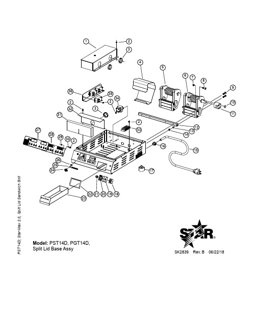
D9-Z19484
1 BAFFLE,14” EL SPLIT TOP
2E-Z2894
1 TERMINAL BLOCK (304)
2E-05-07-0351 2E-05-07-0350
1
TRANSFORMER 115/10V 6VA TRANSFORMER 230V/10V 6VA
120V, 120C 230V, 240V
2C-Z19490
1 SCREW, 10-32 X 3/8 PH
2E-Z2898
1 CONDUIT ASSY. - PTFE
2C-Z3917
2 RIVET, POP, .188 (AD66BS)
2C-Z3780
2 RETAINER, CONDUIT
2A-Z3827
1 PLATE,STAMPING - CONDUIT
1
CONTROL, DUAL CONTROL PROGRAMMING
PGT14DTH-120
2K-Z1971
6 SPACER .257X.75X.25 NYLON
2K-08-07-0004 6 SPACER ROUND NYLON
D9-Z19332
1 INSULATION,TMR & ELE CTRL
PST14D PGT14D
2C-20301-20
4 8
NUT LOCK STOVER 1/4-20
PST14D PGT14D
2E-Z4119
POWER CORD, 12/3, 5-20P
120V
2E-Z19339
POWER CORD, 5-30P
120C
2E-Y9251
1 CORD SET CONT EUR 16AMP
星火热食商务机器产品说明书

1 PILOT LIGHT ASSEMBLY 2 RETAINER - FULL PAN RACK
1 PAN RACK ASSEMBLY 2 RETAINER - HALF PAN RACK
1 HALF PAN RACK ASSEMBLY 16 TIP - ROD
2 PAN - FULL 3 WIRE GRATE - FULL PAN
STAR INTERNATIONAL HOLDINGS INC., COMPANY
2
2
1 3
PARTS LIST
4/01/2010
Fig No 1 2 3
NI
Part No
D4-12955 2A-Y6131 2D-Y1143 2D-Y6452 2Q-Y5956 2Q-Y6204 2Q-Y6203 2C-Y1136 D4-Y6399 2R-Y6087 2I-Y6261 D4-Y6244 2K-Y3240 2K-7889 D4-12931 D4-12932 2R-Y5092 2R-Y1334 2E-Y6144 2B-Y5980 2R-9193 2R-Y5682 2J-6402 2J-6403 D4-12917 D4-12928 2N-Y5958 2N-Y6222 2N-Y6223 D4-12941 2S-Y6281 2S-H8046 D4-12965 D4-Y6560
1 GLASS - LOWER FRONT 4 SOCKET ASSEMBLY
4
LAMP, 40 WATTS LAMP, 50 WATTS
1 TOP SHIELD ASSEMBLY COMPLETE 1 SHELF SHIELD ASSEMBLY COMPLETE
1 BUSHING - STRAIN RELIEF
测温仪的使用手册说明书

探测器 160 x 120 2 GB SD 卡可储存大于 1500 张图像 最小焦距 10 cm。 • testo 875-2: 标配广角镜头 32° x 23 探测器 160 x 120 2 GB SD 卡可储存大于 1500 张图像 最小焦距 10 cm 可见光拍摄, 可更换镜头, 显示表面湿度分布。
5 首要步骤 ..................................................................................................13 5.1 调试 ...............................................................................................13 5.2 其他附件 ........................................................................................15
保修延长
购买产品后在半年内回寄保修登记卡,或登陆网站
进入“服务与支持”页面进行注册,并提供发票信息至 testo,即免费 得 6 个月延长保修。
维护保养协议 仪器过了保修期也不用担心,您可以用经济的价格购买我们的维护保养 服务。
上门取货服务 当产品产生了些许故障,您无须辛苦地奔波,拿起话筒拨打热线电话 021-5456 9696-800。我们会有便捷的上门取货服务,让您足不出户解 决问题。
- 1、下载文档前请自行甄别文档内容的完整性,平台不提供额外的编辑、内容补充、找答案等附加服务。
- 2、"仅部分预览"的文档,不可在线预览部分如存在完整性等问题,可反馈申请退款(可完整预览的文档不适用该条件!)。
- 3、如文档侵犯您的权益,请联系客服反馈,我们会尽快为您处理(人工客服工作时间:9:00-18:30)。
端子名
1:正反转脉冲列
F8104 设定值 2:符号脉冲列
3:二相脉冲列
RF 指令值输入 RF 指令值反转输入
正转脉冲
脉冲列
A 相脉冲
RB 指令值输入
RB 指令值反转输入
反转脉冲
符号
B 相脉冲
※指令值脉冲电压请输入5V。
② SC-PG2、3(开路集电极/推挽)
端子名
RF+ 指令值输入 RF- 指令值输入 RB+ 指令值输入 RB- 指令值输入
绞电缆(开路集电极连接时)。 配线方法②: 是编码器使用外部电源的方法。
开路集电极型 PG
推挽(Complementary)型 PG
・请将 PG 信号线屏蔽层连接在“接地中继端子”TA1。连接在端子 TA1 的屏蔽层长度应尽 量缩短。
・请将端子 TA1 与装置接地端子连接(单独配线)。 ・请将端子 TA1 与端子 TB1(COM)连接。 ・端子 TB1(A1+/ B1+, COM)与外部电源的连接请使用双绞线(开路集电极连接时)。
-7 -
3.相关功能码
以PG脉冲作为速度反馈信号,可进行速度反馈控制及位置控制(F1001=2,5,6)。
3-1
Code No. F1001
相关功能码
功能名称
电机控制模式选择
F1002 1 速频率选择
F1101 运转指令选择 F1202 状态监控显示选择
F1412 MBS 端子输入模式
F1414 F1415 F1416 F1417 F1418 F1419 F1420 F1421
5、使用注意事项・・・・・・・・・・・・・・・・・・・・・・・・・・・ 29 6、规格・・・・・・・・・・・・・・・・・・・・・・・・・・・・・・・ 31
-1 -
1.概要
PG 反馈基板(SC-PG1、SC-PG2、SC-PG3)是用于将脉冲输出型转速检测器(PG:旋转编码器) 连接于 SAMCO-SVC06 / SAMCO-Vm06 系列的选购基板。
・请将 SW1 切换到“EXT”侧。 ・请将 PG 信号线屏蔽层连接到“接地中继端子”TA1。连接在端子 TA1 的屏蔽层长度应尽
量缩短。 ・请将端子 TA1 与装置接地端子连接(单独配线)。 ・请将端子 TB2(5G)与 TA1 连接。 ・外部电源与端子 TB2(5V,5G)的连接请使用双股扭绞电缆。
A2 总线驱动器 A 相反转输入(CH2)
B2 总线驱动器 B 相输入(CH2)
B2 总线驱动器 B 相反转输入(CH2)
注意 1:请尽量将外部电源A相、B相及主机电源予以绝缘。
注意 2:A 相脉冲、B 相脉冲的相位因 PG 规格而异,请予以注意。若是反接的话,其动作将不稳定。
② 开路集电极/推挽(SC-PG2、SC-PG3)
(2) 关于 PG 信号线的选定 SC-PG2、3 选购件的 PG 信号线请使用屏蔽线。
(3) 关于 SC-PG2,3 选购件的配线方法
接地中继端子TA1
SC-PG3 选购件的配线方法有 2 种。本公司推荐采用配线方法①。当 PG 信号受到噪音影响
时,请尝试配线方法②。另外,PG2 选购件的推荐采用接线方法②。
1:正反转脉冲列 正转脉冲
反转脉冲
F8104 设定值 2:符号脉冲列
脉冲列
符号
3:二相脉冲列 A 相脉冲
B 相脉冲
1-5 脉冲监控器输出端子
只有被输入到主 PG(CH1)的信号将被输出到脉冲监控器输出端子,而被输入到辅助 PG(CH2)
的信号将不被输出。
① SC-PG1(总线驱动器)
端子名
端子名
MA 总线驱动器 A 相输出
开路集电极 A2 相 **V外部电源 推挽 A2 相**V脉冲输入
B2+
开路集电极 B2 相 **V外部电源 推挽 B2 相**V脉冲输入
A2-
开路集电极 A2 相 **V脉冲输入 推挽 A2 相**VGND
B2-
开路集电极 B2 相 **V脉冲输入 推挽 B2 相**VGND
注意 1:请尽量将外部电源 A 相、B 相及主机电源予以绝缘。
具备反馈电机转速的速度控制功能和位置控制功能。对于转矩控制,也可以通过使用 PG 传感器,提高其控制性能。
实施反馈的检测器(PG 传感器)可根据选购种类,连接总线驱动器型(SC-PG1)、开路集电 极/推挽型(SC-PG2、SC-PG3)。
1-1 反馈信号输入规格(PG 输入)
选购基板 型式
PG 反馈基板 SC-PG1,SC-PG2,SC-PG3
使用说明书
非常感谢您购买
、
PG 反馈基板(SC-PG)。
本产品为高性能变频器
、
专用的内置选购
基板 SC-PG1(总线驱动器型)、SC-PG2、SC-PG3(开路集电极/推挽型)。在使用
前请务必阅读本说明书,以便保证长期的使用寿命。
目录
1、概要・・・・・・・・・・・・・・・・・・・・・・・・・・・・・・・2 2、安装・・・・・・・・・・・・・・・・・・・・・・・・・・・・・・・4 3、相关功能码・・・・・・・・・・・・・・・・・・・・・・・・・・・・8 4、设定步骤・・・・・・・・・・・・・・・・・・・・・・・・・・・・13
负 正转脉冲列 反转脉冲列
逻 脉冲列+符号
辑 A 相脉冲列 B 相脉冲列
正转时
RF
RB
RF
RB
H
RF
RB
RF
RB
RF
RB
L
RF
RB
反转时
L H
1-4 指令值信号输入端子
指令值信号输入端子根据指令脉冲形态(F8104)的设定,其输入方式发生变化。请对照使
用脉冲形态进行连接。
① SC-PG1(总线驱动器)
1-2 PG反馈基板(SC-PG1、SC-PG2、SC-PG3)的安装 当要装卸选购基板时,需先卸下前盖(上)。 在前盖(下)卸下状态下,按住前盖(上)两侧面的肋拱,向近前拉拔将其卸下。
M3 螺钉固定
选购基板用 插槽 2(OPT2)
选购基板用 插槽 1(OPT1)
按住肋拱
请在选购基板的垫片安装孔上安装好附带的垫片。
最大输入脉冲频率: 250KHz
※1:为单相脉冲输入时的最大频率。
1-2 PG 反馈信号输入端子
① 总线驱动器(SC-PG1)
端子名
端子名
A1 总线驱动器 A 相输入(CH1)
A1 总线驱动器 A 相反转输入(CH1)
B1 总线驱动器 B 相输入(CH1)
B1 总线驱动器 B 相反转输入(CH1)
A2 总线驱动器 A 相输入(CH2)
注意 2:请注意 A 相脉冲、B 相脉冲的相位因 PG 规格而异。若是反接的话,其动作将不稳定。
注意 3:**表示电源电压。SC-PG2(对应 12V 电源)、SC-PG3(对应 24V 电源)
-2 -
1-3
指令值信号输入规格
指令脉冲列形态
正 正转脉冲列 反转脉冲列
逻 脉冲列+符号
辑 A 相脉冲列 B 相脉冲列
配线方法①(本公司推荐): 编码器使用内部电源的方法。
-6 -
开路集电极型 PG
・请将 PG 信号线屏蔽层连接在“接地中继端子”TA1。连接在端子 TA1 的屏蔽层长度应尽 量缩短。
・请将端子 TA1 与装置接地端子连接(单独配线)。 ・请将端子 TA1 与端子 TB1(COM)连接。 ・端子 TB1(A1+/ B1+, COM)与控制端子(+24V1/ +24V2, DCM1/ DCM2)的连接请使用双
MA 总线驱动器 B 相反转输出
MB 总线驱动器 B 相输出
MB 总线驱动器 B 相反转输出
② SC-PG2、3(开路集电极/推挽)
端子名
MA 开路集电极 A 相输出
MB 开路集电极 B 相输出 ※MG 端子和 COM 端子在基板内部连接。
端子名
MV
电 源 端 子 (SC-PG2:12V / SC-PG3:24V)
端子名
端子名
A1+
开路集电极 A1 相 **V外部电源 推挽 A1 相**V脉冲输入
B1+
开路集电极 B1 相 **V外部电源 推挽 B1 相**V脉冲输入
A1-
开路集电极 A1 相 **V脉冲输入 推挽 A1 相**VGND
B1-
开路集电极 B1 相 **V脉冲输入 推挽 B1 相**VGND
A2+
端子台 TB1: COM COM B2- B2+ A2- A2+ B1- B1+ A1- A1+ 端子台 TB2: MG MB MA MV RB- RB+ RF- RF+
(1) 关于 PG 信号线的设置 PG 信号线配线(端子台 TB1、TB2)请与主电路配线及其 他动力线或电力线分离。
端子台TB2 端子台TB1
2-3-1 SC-PG1 SC-PG1 端子配置如以下所记:
端子台 TB1: RF RF B2 B2 A2 A2 B1 B1 A1 A1 端子台 TB2: 5G 5V MB MB MA MA RB RB
EXT INT
SW1 电源切换开关 端子台TB2
(1) 关于 PG 信号线的设置 PG 信号线配线(端子台 TB1、TB2)请与主电路配线及 其他动力线或电力线分离。
规格
输入信道: 2 路系统
SC-PG1
输入信号形式: 总线驱动器(电源电压 5V)
最大输入脉冲频率: 500 KHz(※1)
输入信道: 2 路2V)
最大输入脉冲频率 250KHz
