SMTD-160中文资料
Bulletin 160 SSC Remote Keypad FRN 1.x 用户手册说明书
Important User InformationSolid-State equipment has operational characteristics differing from those ofelectromechanical equipment. “Safety Guidelines for the Application, Installationand Maintenance of Solid-State Controls” (Publication SGI-1.1) describes someimportant differences between solid-state equipment and hard-wiredelectromechanical devices. Because of this difference, and also because of the widevariety of uses for solid-state equipment, all persons responsible for applying thisequipment must satisfy themselves that each intended application of this equipmentis acceptable.In no event will Rockwell Automation be responsible or liable for indirect orconsequential damages resulting from the use or application of this equipment.The examples and diagrams in this manual are included solely for illustrativepurposes. Because of the many variables and requirements associated with anyparticular installation, Rockwell Automation cannot assume responsibility orliability for actual use based on the examples and diagrams.No patent liability is assumed by Rockwell Automation with respect to use ofinformation, circuits, equipment, or software described in this manual.Reproduction of the contents of this manual, in whole or in part, without writtenpermission of Rockwell Automation is prohibited.Throughout this manual we use notes to make you aware of safety considerations:SSC is a trademark of Rockwell Automation, Inc.Table of Contents IntroductionDrive Compatibility . . . . . . . . . . . . . . . . . . . . . . . . . . . . . . . . . . . . . . . . . . . . . . . . . . . . . . . . . . . . . . .1-1Related Publications . . . . . . . . . . . . . . . . . . . . . . . . . . . . . . . . . . . . . . . . . . . . . . . . . . . . . . . . . . . . . .1-1Remote Programming Adapter . . . . . . . . . . . . . . . . . . . . . . . . . . . . . . . . . . . . . . . . . . . . . . . . . . . . . .1-2 Removal and Installation . . . . . . . . . . . . . . . . . . . . . . . . . . . . . . . . . . . . . . . . . . . . . . . . . . .1-2Grounding . . . . . . . . . . . . . . . . . . . . . . . . . . . . . . . . . . . . . . . . . . . . . . . . . . . . . . . . . . . . . .1-3 Connector Cable . . . . . . . . . . . . . . . . . . . . . . . . . . . . . . . . . . . . . . . . . . . . . . . . . . . . . . . . . . . . . . . . .1-4Features . . . . . . . . . . . . . . . . . . . . . . . . . . . . . . . . . . . . . . . . . . . . . . . . . . . . . . . . . . . . . . . . . . . . . . .1-5Display Description . . . . . . . . . . . . . . . . . . . . . . . . . . . . . . . . . . . . . . . . . . . . . . . . . . . . . . . . . . . . . . .1-6Drive Status Indicators . . . . . . . . . . . . . . . . . . . . . . . . . . . . . . . . . . . . . . . . . . . . . . . . . . . . . . . . . . . .1-6Keypad Initialization Sequence . . . . . . . . . . . . . . . . . . . . . . . . . . . . . . . . . . . . . . . . . . . . . . . . . . . . . .1-7 InstallationPrepare Mounting Location . . . . . . . . . . . . . . . . . . . . . . . . . . . . . . . . . . . . . . . . . . . . . . . . . . . . . . . . .2-1Mount the Remote Keypad . . . . . . . . . . . . . . . . . . . . . . . . . . . . . . . . . . . . . . . . . . . . . . . . . . . . . . . . .2-2 Control the DriveEnable Keypad Control to Start the Drive . . . . . . . . . . . . . . . . . . . . . . . . . . . . . . . . . . . . . . . . . . . . . .3-1Save Changes to Parameter 46 . . . . . . . . . . . . . . . . . . . . . . . . . . . . . . . . . . . . . . . . . . . . . . . . . . . . .3-1Stop the Drive . . . . . . . . . . . . . . . . . . . . . . . . . . . . . . . . . . . . . . . . . . . . . . . . . . . . . . . . . . . . . . . . . . .3-2Change Direction of Motor Rotation . . . . . . . . . . . . . . . . . . . . . . . . . . . . . . . . . . . . . . . . . . . . . . . . . .3-2 TroubleshootingHow to Clear a Fault . . . . . . . . . . . . . . . . . . . . . . . . . . . . . . . . . . . . . . . . . . . . . . . . . . . . . . . . . . . . . .4-1Resolving Problems . . . . . . . . . . . . . . . . . . . . . . . . . . . . . . . . . . . . . . . . . . . . . . . . . . . . . . . . . . . . . .4-2 Technical SpecificationsDimensions . . . . . . . . . . . . . . . . . . . . . . . . . . . . . . . . . . . . . . . . . . . . . . . . . . . . . . . . . . . . . . . . . . . . .A-1 Ambient Conditions . . . . . . . . . . . . . . . . . . . . . . . . . . . . . . . . . . . . . . . . . . . . . . . . . . . . . . . . . . . . . . .A-1 Input/Output Ratings . . . . . . . . . . . . . . . . . . . . . . . . . . . . . . . . . . . . . . . . . . . . . . . . . . . . . . . . . . . . . .A-1 Approvals and Standards Compliance . . . . . . . . . . . . . . . . . . . . . . . . . . . . . . . . . . . . . . . . . . . . . . . .A-1 Maintenance . . . . . . . . . . . . . . . . . . . . . . . . . . . . . . . . . . . . . . . . . . . . . . . . . . . . . . . . . . . . . . . . . . . .A-2iiChapter 1Introduction The Remote Keypad can be used to change drive parameter values, monitoroperating conditions, and control drive operation.Important:The four-character Remote Keypad display requires an extrakeystroke in order to display a current parameter value. See feature4 on page 1-5 and step 4 on page 3-1.Remote Keypad Figure 1.1Drive CompatibilityThe Remote Keypad is compatible with Bulletin 160 SSC™ Variable Speed SeriesC drives using firmware version FRN 7.01 or higher.Related PublicationsPrior to using the Remote Keypad, please familiarize yourself with the followingpublications for complete parameter and fault descriptions and detailedinformation about hazards associated with AC drives.•160 SSC™ Variable Speed Drive (Series C) User Manual,Publication 0160-5.15•160 SSC™ Variable Speed Drive Quick Reference Series C,Publication 0160-5.161-2IntroductionRemote Programming AdapterThe Remote Programming Adapter (160-RPA) allows the Remote Keypad tointerface with a Bulletin 160 Series C drive.If your drive is equiped with a Ready/Fault Indicating Panel (160-B1) or a ProgramKeypad Module (160-P1), you must remove these modules and install a RemoteProgramming Adapter in order to use the Remote Keypad.Removal and InstallationInsert a small screw driver into the slot at top of panel/keypad. Carefully pry backand pivot the module out. Avoid bending or twisting the contact pins locatedunderneath the center portion of the module.Insert the RPA module, bottom first, into the drive. Press down on the top cornersof the module until it is firmly seated.Module Removal and Adapter Installation Figure 1.2Introduction1-3 GroundingIt is required that the Remote Programming Adapter be earth grounded to improvenoise immunity and to guard the Remote Keypad against hazardous DC buspotential voltages.1-4IntroductionConnector CableA cable is used to connect the Remote Keypad to the Bulletin 160 Series C drive.The Keypad can be connected and disconnected when the drive is under power.Important:If P46 - [Input Mode] is set to 2 or 6, disconnecting the RemoteKeypad will cause the drive to fault.The following connector cables are available and purchased separately.•160-C10 – 1 meter cable, non-locking•160-C10R – 1 meter cable, non-locking with right angle for minimal depth•160-C30 – 3 meter cable, locking each end•160-C50 – 5 meter cable, locking each endThe 3- and 5-meter connector cables have a locking mechanism to ensure that thecable will not be disconnected accidentally. The 1-meter connector cables do nothave a locking mechanism. To remove the cable from the drive or the RemoteKeypad, pull back on the plastic housing of the cable connector.Introduction 1-5FeaturesThe figure and table below identify and describe the Remote Keypad display, status indicators, and keys.Remote Keypad Features Figure 1.6 FeatureDescription 1Display Four 7-segment light emitting diodes (LEDs)2Indicator LEDs Four LEDs indicate mode of operation.3Escape Key •Press to toggle between Display mode and Program mode.•In Edit mode, press to cancel an edit sequence and return to Programmode.4Enter Key •In Display or Program modes, press to toggle between parameter numbersand values.•In Edit mode, press to save a new parameter value.5Select Key In Program mode with a parameter value displayed, press to enter Edit mode.Use the Up or Down arrow keys to change the parameter value.6Up and Down Arrow Keys •In Program mode, use to scroll Program Group parameter numbers orchange a parameter value.•In Display mode, use to scroll Display Group parameters numbers.7Reverse Key Changes direction of motor rotation when keypad control is selected(P46 = 2 or 6) and reverse is enabled (P73 = 0)8Start Key Issues a start command to drive when keypad control is selected(P46 = 2 or 6).9Stop Key •Issues a stop command to drive.•Press to reset a fault after taking corrective action.1-6 IntroductionDisplay DescriptionThe keypad has a four-character LED display which shows parameter numbers, parameter values, and fault codes. The keypad monitors its connection to the drive. If this connection fails due to electrical noise or a hardware failure, the following is displayed.If the drive faults, the display will flash indicating the presence of the fault, and the fault code will be displayed. Pressing the Up or Down arrow, Enter, or Escape key will return the keypad to Display mode. If the fault condition is reset without pressing one of these keys, the display will return to the display or program parameter that was selected prior to the occurrence of the fault.Drive Status IndicatorsThe keypad has four status LEDs which serve as mode and direction indicators.LED FunctionsT able 1.B NameStatus DescriptionPROGRAM OnThe keypad is in Program mode.OffThe keypad is in Display mode.FlashingThe keypad is in Edit mode.RUNOn The drive is running.FORWARDOn If keypad control is selected (P46 = 2 or 6), this LED will turn onif the direction commanded by the keypad is forward.If keypad control is not selected, this LED will turn on when thedrive is running forward.Flashing The FORWARD LED will flash when the drive is commanded tochange direction from forward to reverse and will stop flashingwhen the motor decelerates to zero. The REVERSE LED willilluminate indicating the commanded direction.REVERSE On If keypad control is selected (P46 = 2 or 6), this LED will turn onif the direction commanded by the keypad is reverse.If keypad control is not selected, this LED will turn on when thedrive is running reverse.Flashing The REVERSE LED will flash when the drive is commanded tochange direction from reverse to forward and will stop flashingwhen the motor decelerates to zero. The FORWARD LED willilluminate indicating the commanded direction.Introduction1-7 Keypad Initialization SequenceWhen the Remote Keypad is connected to the drive, and power is applied, thefollowing is displayed for approximately two seconds.After two seconds have elapsed, the keypad will display the current value of thelast Display Group parameter selected. In this example, P01 - [Output Frequency] isat 0.0 Hertz.1-8Introduction End of ChapterChapter 2InstallationPrepare Mounting Location•Select a mounting location that is less than 5 meters away from the drive.Connection cables are available in 1, 3, and 5 meter lengths.•Install in a suitable IP55 or IP65 rated enclosure.Drilling Pattern and Dimensions Figure 2.12-2InstallationMount the Remote KeypadInstallation and T orque Sequence Figure 2.2Chapter 3Control the Drive Enable Keypad Control to Start the DriveThe following steps also serve as a programming example.1.With the Remote Keypad installed and connected to the Bulletin 160 Series Cdrive, power up the drive.The Remote Keypad always powers up in the Display mode. While in thismode you may view all read only drive parameters, but not modify them.2.Press the Escape key to enter the Program mode.The Program LED will light and Parameter 30 is displayed.e the Up or Down arrow key to scroll to P46 - [Input Mode].4.Press the Enter key to display the parameter value.5.Press the Select key to enter the Edit mode.The Program LED will flash indicating that the parameter value may bechanged.6.Change P46 - [Input Mode] to 2 or 6 using the Up or Down arrow key.7.Press the Enter key to save the new value.The Program LED will stop flashing and remain lit.Important:When P46 - [Input Mode] is set to 2 or 6, disconnecting the RemoteKeypad will cause the drive to fault.Save Changes to Parameter 46In order for changes to P46 - [Input Mode] to take effect, cycle power or setP56 - [Reset Functions] to 2.e the Up or Down arrow key to scroll to P56 - [Reset Functions].2.Press the Enter key to display the default parameter value of 0.3.Press the Select key to enter the Edit mode.4.Change P56 - [Reset Functions] to 2 using the Up or Down arrow key.5.Press the Enter key to save the new value.The new P46 - [Input Mode] value is saved and P56 - [Reset Functions] resets to 0.You can now use the Remote Keypad to start the drive.Important:The Stop/Reset digital input on the drive (TB3-8) must bemaintained in the ON state for the keypad to start the drive.3-2Control the DriveStop the DriveUse the Stop key to command the drive to stop. The Stop key functions in all driveinput modes whether or not the keypad is selected as the drive’s control source.Change Direction of Motor RotationOnce the Remote Keypad is set to control drive operation (P46 - [Input Mode] is setto 2 or 6) you can change the direction of motor rotation by pressing the Reverse key.When the motor is running, pressing the Reverse key causes the motor to rampdown to 0 Hz and then ramp up to its set speed in the opposite direction.Chapter 4TroubleshootingHow to Clear a FaultWhen a fault occurs, the cause must be corrected before the fault can be cleared.After corrective action has been taken, any of the following actions will clear thefault.•Press the Remote Keypad Stop button•Set P54 - [Clear Fault] to 1.•Disconnect power to the drive, wait three minutes, reapply power.•Cycle the input signal at TB3-8 to the drive.Please consult the 160 SSC™ Variable Speed Drive (Series C) User Manual,Publication 0160-5.15, for a complete listing of fault descriptions and possibleproblems and corrective actions.4-2Troubleshooting DRAFT – 7/19/99 Resolving ProblemsImportant:The connector cable, RPA, and Keypad are not repairable.Appendix ATechnical Specifications DimensionsAmbient Conditions•Operating temperature: 0˚ C to 50˚ C (32˚ F to 122˚ F)•Storage temperature: -40˚ C to 85˚ C (-40˚ F to 185˚ F)•Relative humidity: 0 to 95%, non-condensing.Input/Output Ratings•Input voltage: 5 VDC (from drive power supply)•Input current: 75 mA (maximum, from drive power supply)Approvals and Standards Compliance•UL508C•CSA 22.2•CE•EN-50178•IP 66 (NEMA Type 12/UL Type 4X Indoor)A-2Technical SpecificationsMaintenanceUse only a soft cloth dampened with water to clean the keypad.The RPA requires no maintenance or cleaning.Publication 0160-5.28ML – September, 1999P/N 194308 (01)Copyright 1999 Rockwell International Corporation. All rights reserved. Printed in USA.。
DS160 DS161
Push to Exit Alarm will Sound
Push to Exit Alarm will Sound
Push to Exit Alarm will Sound
大门上方
天花板 两扇门上方
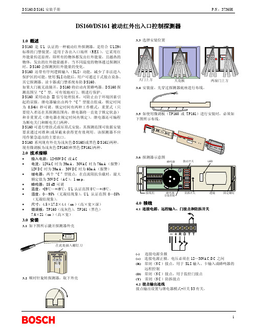
3.4 安装前,先穿过探测器底座进行布线。
3.5 如使用微调板(TP160 或 TP161)进行安装时,必须如 下图所示布线。
DS160/DS161 安装手册
P/N:37365K
DS160/DS161 被动红外出入口控制探测器
1.0 概述
DS160 是 UL 认证的一种被动红外探测器,是符合 UL294 标准的门禁装置,适用于各出入口场所(REX)。它采用红 外能量传送原理,即所有的物体都发出红外能量,且越热的 物体,发出的红外能量越多。当不同温度的物体通过探测区 时,DS160 会探测到红外能量的变化。 DS160 还带有序列逻辑输入(SLI)功能,减少了非法进入 保护区的可能。使用 SLI 功能后,用户可通过干式接点设备、 其它探测器、读卡器或门禁系统布防 DS160。 如果大门被无故撞开,DS160 将启动内置蜂鸣器。DS160 探 测范围呈“C”型,可有效地对门、锁进行保护。 DS160 采用动态 II 信号处理技术,可防止由于环境因素引 起的误报。继电器输出由两个“C”型接点组成,锁定时间 为 0.5-64 秒可调。锁定时间有两种工作模式:重置式(只 要侵入者还在其探测范围内,继电器将一直处于锁定状态) 和非重置式(继电器在规定时间内锁定)。继电器还可编程 为断电关门和断电关门两种。 DS160 可进行壁挂式或吊顶式安装,其探测范围可依据安装 要求通过对准和/或屏蔽来获得更有效利用。该探测器不应 用作紧急退出的主要出口。 DS160 系列现有外壳为浅灰色(DS160)或黑色(DS161)两种。 现有微调板为浅灰色(TP160)和黑色(TP161)两种。
DO-160上课讲义

DO160电磁兼容测试系统RTCA DO-160《机载设备环境条件与测试规程》是由RTCA(航空无线电技术委员会)下属的SC135特别委员会起草制定的,DO-160规定的测试是为满足联邦航空管理局(FAA)或者其他国际规定对安装在商业航空器上设备的要求而进行的典型测试。
DO-160包括26个部分和三个附件,包括有:温度、高度、振动、沙/尘、电源输入、射频敏感度、雷击和静电放电等测试内容,但是只有15至23节和25节与电磁兼容相关。
其中的第22节为“雷电感应瞬变敏感度”,第23节为“雷电直接效应”,这两类测试是DO-160的特色内容,充分考虑到了实际工作的雷电环境对航空飞行器的影响。
DO-160涵盖了航空电气电子设备(航空电子学)的标准步骤和环境测试标准,适用对象包括了所有的航空飞行器,从轻型到重型,从小型到大型,如小型通用航空器、商业喷气式飞机、直升机、区域喷气式飞机和巨型喷气式飞机。
它提供了一整套实验室测试方法以判定被测对象在模拟的环境条件下是否满足规定的性能指标要求。
目前,DO-160已更新至G版本(2010年12月发布)。
DO-160的制定和修正与RTCA的欧盟版本:EUROCAE相配合,作为横跨大西洋的两个组织的合作成果,DO-160F与它的欧洲版本EUROCAE ED-14F 完全一致。
DO-160中提供的建议和方法经常被用作政府部门及企业决策的依据,也是美国联邦航空局(FAA)许多技术标准指令的基础。
该标准在国际航空领域有着极大的影响力和广泛应用,目前我国很多飞机项目的设计和验证均参照DO-160。
RTCA DO-160标准规定了航空机载设备的环境条件和试验程序,其中与EMC相关的测试项目有九个章节。
爱邦电磁依据该标准,结合丰富的EMC测试经验,面向航空领域提供专业的测试系统集成业务。
测试系统可以分为如下几部分:1. 射频能量发射(RTCA DO-160 Sec 21)2. 射频敏感度(RTCA DO-160 Sec 20)3. 电源线音频信号及感应信号敏感度(RTCA DO-160 Sec 18&19)4. 电压尖峰测试(RTCA DO-160 Sec 17)磁场效应、电源输入和静电放电测试(RTCA DO-160 Sec 15、16、25)均有专用的仪器实现测试,不需要系统集成。
SMT元器件培训资料
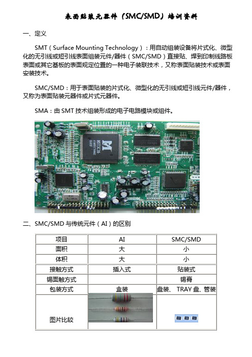
表面贴装元器件(SMC/SMD)培训资料一、定义SMT(Surface Mounting Technology):用自动组装设备将片式化、微型化的无引线或短引线表面组装元件/器件(SMC/SMD)直接贴、焊到印制线路板表面或其它基板的表面规定位置的一种电子装联技术,又称表面贴装技术或表面安装技术。
SMC/SMD:用于表面贴装的片式化、微型化的无引线或短引线元件/器件,又称为表面贴装元器件或片式元器件。
SMA:由SMT技术组装形成的电子电路模块或组件。
二、SMC/SMD与传统元件(AI)的区别三、SMC/SMD 分类SMC/SMD 根据在电路中所起的不同作用,有很多种分类,常用的SMC/SMD 有片式电阻、片式电阻排、片式瓷介、片式二极管、片式三极管、片式磁珠、片式IC 、片式插座等。
1、片式电阻RC 0805 F R --- 07 1K47① ② ③ ④ ⑤ ⑥说明:① RC=普通应用贴片电阻②尺寸:如:0402(表示长×宽=0.04″×0.02″=1mm ×0.5mm )、0603、0805、1206 ③误差:B=±0.1%、C=±0.25%、D=±0.5%、F=±1%、G=±2%、J=±5%、K=±10% ④编带形式:R=纸带、K=塑料带、B=散装(袋式)、C=盒装⑤卷带尺寸:07=7″、10=10″、13=13″⑥阻值:如0R 、0R1、100R 、1K 、10K 、100K 、1M 、10M片式电阻表面标识转换为实际阻值示例:104表示10×104Ω=100K Ω,330表示33×100=33Ω,并不表示104Ω或330Ω,要特别注意。
2、片式电阻排(电阻网络):将几个单独的电阻,按预定的配置要求加以连接后置于一个组装体内的表面组装元件,片式电阻排无极性。
如:片式电阻排\YC164JR-07-33R 、片式电阻排\YC164JR-07-4K73、片式瓷介CC 0805 K K X7R 9 B N 104① ②③④ ⑤ ⑥⑦ ⑧ ⑨说明:①CC=多层式片状电容器②尺寸:如:0402、0603、0805、1206③误差:C=±0.25PF 、D=±0.5PF 、F=±1%、G=±2%、J=±5%、K=±10%、M=±20%、Z=-20%∽+80%④包装:R=7”卷式纸带、P=13”卷式纸带、K=7”卷式塑带、F=13”卷式塑带、B=散装(袋式)、C=盒装⑤温度系数(介质):NPO 、X7R 、Z5U 、Y5V⑥额定电压:5=6.3V 、6=10V 、7=16V 、8=25V 、9=50V 、0=100V 、A=200V 、B=500V 、C=1KV 、D=2KV 、E=3KV 、H=4KV 、Y=250V⑦端接: A=钯银、B=镍锌⑧专门代码:B=X7R/Y5U 、N=NPO⑨容值:示例0R5=0.5PF 、R75=0.75PF 、010=1PF 、100=10PF 、101=100PF 、103=10000PF 注意:由于片式瓷片表面无容量值标识,在使用过程中必须特别注意包装上的标识,对于数量较少或无包装的片式瓷片,必须用标识单注明型号、数量,避免用错。
SMT学习专用资料

SMT 培训资料贴片机简介贴片机又叫SMT,它是英语SURFACE MOUNT TECHNOLOGY 的代写;意为:表面贴装技术。
我们在电子元件封装的描述时,经常看到CHIP这一个单词,它的含义为:条;长条;条形;在专业术语方面可以直译为:表面贴装元件。
SMT是专门用于表面贴装电子元件的安装。
近年来,随着电子技术的发展,集成化、小型化、低功耗、高可靠性是电子行业的必然道路。
贴片机也随之诞生。
CASIO YCM-8800VF型的贴片机是中速机,由四个机械手,而每个机械手上面又有两个贴片头。
作业时,PCB板先进入轨道,然后托盘上升,上面的支柱顶在PCB板上;将PCB板固定好。
之后,系统由软件控制进行坐标点和MARK点的校对。
如MARK点位置正确,则系统载入已编入的PCB板资料,由机械手和贴片头相互协调完成贴片作业。
如MARK点位置不正确,则系统将PCB板送出,并报警。
贴片机的供料也是自动完成。
具体的供料位置在编程时,系统自动分配;而操作员则安照指定的位置放置电子元件即可。
SMT操作员和品质管理人员的职责是:1、正确处理设备常见的警告程序;2、正确供料,包括元件封装类型的确认,元件的放置位置,元件的放置方向,以及设备的守护及看管;3、对作业输出状态的确认;4、异常情况的处理及报告等。
5、未经许可,任何人不得靠近SMT机器;6、非SMT编程人员,任何人不得对机器进行调试或改写、查看程式;7、凡进入SMT工作车间的人员,必须戴防静电环、穿防静电服和防静电帽。
SMT是十分精密的设备,程序的操作在不是十分懂的情况下,切忌盲目操作。
常用的贴片元件一、电阻物体对电流通过时的阻碍作用称为“电阻”;利用这种阻碍作用做成的元件称为电阻器,简称电阻。
常用R和。
在PCB和两种。
贴片元件的电阻数值在一般情况下,是直接用数字标识在元件上面;它的表示意义如下:数值一般由三位或四位,最后一位表示的是倍率,前面为有效位;如贴片电阻的102表示1KΩ;贴片电阻的4722表示47.2KΩ。
PM-160说明书

REV 3.7
上海泗博自动化技术有限公司
SiboTech Automation Co., Ltd.
技术支持热线:021-3126 5138 E-mail: .................................................................................................................................................... 3 1.1 产品功能 ................................................................................................................................................. 3 1.2 产品特点 ................................................................................................................................................. 3 1.3 技术指标 ................................................................................................................................................. 3 1.4 电磁兼容性能........................................................................................................................................ 5 1.4.1 高频干扰试验(GB/T15153.1 classⅢ) .................................................................................. 5 1.4.2 快速瞬变脉冲群试验(GB/T17626.4 classⅢ) .................................................................... 5 1.4.3 静电放电干扰(GB/T 17626.2 classⅢ) ................................................................................. 5 1.4.4 辐射电磁场(GB/T 17626.3 classⅢ) ..................................................................................... 5
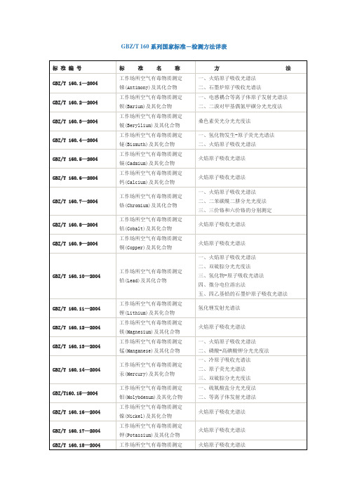
GBZT 160系列国家标准-检测方法详表
三、异丁醛的热解吸-气相色谱法
四、甲醛的酚试剂分光光度法
五、糠醛的苯胺分光光度法
GBZ/T 160.55—2004
工作场所空气有毒物质测定
脂肪族酮类(Aliphatic ketones)化合物
一、丙酮、丁酮和甲基异丁基甲酮的溶剂解吸-气相色谱法
二、丙酮、丁酮、甲基异丁基甲酮和双乙烯酮的热解吸-气相色谱法
三、三价铬和六价铬的分别测定
GBZ/T 160.8—2004
工作场所空气有毒物质测定
钴(Cobalt)及其化合物
火焰原子吸收光谱法
GBZ/T 160.9—2004
工作场所空气有毒物质测定
铜(Copper)及其化合物
火焰原子吸收光谱法
GBZ/T 160.10—2004
工作场所空气有毒物质测定
铅(Lead)及其化合物
GBZ/T 160.42—2004
工作场所空气有毒物质测定
芳香烃类(Aromatichydrocarbons)化合物
一、苯、甲苯、二甲苯、乙苯和苯乙烯的溶剂解吸-气相色谱法
二、苯、甲苯、二甲苯、乙苯和苯乙烯的热解吸-气相色谱法
三、苯、甲苯和二甲苯的无泵型采样-气相色谱法
GBZ/T 160.43—2004
工作场所空气有毒物质测定
醇类(Alcohols)化合物
一、甲醇、异丙醇、丁醇、异戊醇、异辛醇、糠醇、二丙酮醇、丙烯醇、乙二醇和氯乙醇的溶剂解吸-气相色谱法
二、甲醇的热解吸-气相色谱法
三、二氯丙醇的变色酸分光光度法
GBZ/T 160.49—2004
工作场所空气有毒物质测定
硫醇类(Mercaptans)化合物
GBZ/T160.15—2004
SMT各岗位培训资料
MPM培训资料1.1 工作职责1.1.1PCB的来料检查1.1.2保证锡浆印刷质量,2D检测1.1.3锡浆厚度的测试和表格的填写1.1.4每小时按时核对样板1.1.5协助拉后核对好物料1.1.6遇到品质问题或机器突发问题及时通知相关人员1.1.75S1。
2 需要掌握的文件1。
2。
1 PCB的操作指引 DI—43-01051.2.2锡浆搅拌机的操作与检查指引 DI-43-00821.2.3存储箱及烘烤箱指引 DI—43—00111.2.4MPM印刷机器指引 DI—43—00171.2.5送板机操作指引 DI—43-00841.2.6金属刮刀维护指引 DI—43-00871.2.7MPM参数设定指引 FP—M—0101.2.8PCB印刷后的检查指引 DW—60-00661.2.9丝网跟踪记录 FP—I-0291.2.10机器预防性保养记录表 FP—M-0211.2.11锡浆管理登记表 FL—R—0031.3 工作关键控制重点1.3。
1 根据工作指引操作,正确选择钢网,MPM支撑架,刮刀,锡浆以及PCB等;。
1.3.2 使用锡浆时的注意事项:有效期、解冻时间、批号有铅与无铅之分,不要使用过期锡浆.填好相关使用标签记录.1.3。
3 印刷品质.每班正常生产前应检查刚开始2片PCB印刷效果,特别注意大IC、BGA和片位较小的一些元件印锡质量,及时测试锡浆厚度和2D检测,按时核对好样板及表格的填写.1。
3。
4 在生产之前及转产时.要检查送板系统和当前程序是否一致.1.3.5 如果由于机器故障或没有物料等原因而停拉超过10钟, 则需要将丝网上的锡浆刮掉并把它放到密封瓶里,不要和没用过的锡浆混合,等到生产的时候再用,若停拉超过30分钟,则需要清洁丝网和刮刀1.3.6 避免少锡和多锡的现象,锡浆使用超过24小时需报废处理1。
3。
7 PCB开封必须有记录(〈〈湿度敏感元件时间记录表〉> ),超过时间,需要烘烤储存箱的温度25正负5摄氏度。
贴片发光二极管 0603蓝光 1608 SMD LED 灯珠中英文参数资料

230°C Max. 260°C Max.
焊接时间 Soldering time 10 sec. Max. 10 sec. Max.
条件 Condition
参考下图
参考下图
有铅回焊(Lead Solder)
手工焊接 Hand Soldering
温度 Temperature
350°C Max.
焊接时间 Soldering time 3 sec. Max. (one time only)
编制 Prepared by
洸子其确认
CONFIRMATION
审核
核准
Checked by
Approved by
市场部 Market Dept.
确认 Confirmed by
客户确认
CUSTOMER CONFIRMATION
审核
核准
Checked by
Approved by
确认 Confirmed by
30 150 9 100
-40ºC To +85ºC -40ºC To +85ºC
ReflowSoldering:260ºC Hand Soldering : 350ºC
单位 Unit mA mA
V mW °C °C for 10sec. for 3sec.
(2) 样品光电参数 Initial Electrical/Optical Characteristics (TA=25±5ºC)
Keep away from water, moisture in order to protect the LEDs.
(6) 须采取适当防护措施,以防包装箱跌落或受到强力撞击造成对产品的损伤.
SMT电子元件认识
培训资料一.SMT元器件的设计﹑开发﹑生产﹐为SMT的发展提供了物料保证。
常将其分为SMT组件(SMC 含表面安装电阻﹑电容﹑电感)和SMT器件(SMD﹐包含表面安装二极管﹑三极管﹑集成电路等)。
我们常接触的元器件有﹕1﹑表面安装电阻电阻在电子线路中用表示﹐以英文字母R代表﹐其基本单位为奥姆﹐符号为Ω。
换算关系有﹕1兆欧(MΩ)=1000千欧(KΩ)=1000000欧(Ω)。
表面安装电阻的主要参数有﹕阻值﹑电功率﹑误差﹑体积﹑温度系数和材料类型等。
表面安装电阻阻值大小一般丝印于组件表面﹐常用三位数表示。
三位数表示的阻值大小为﹕第一﹑二位为有效数字﹐第三位为在有效数字后添0个数﹐单位为奥姆。
如﹕103 表示10KΩ10000Ω101 表示100Ω124 表示120KΩ120000Ω但对于阻值小的电阻有如下表示6R8…………………….6.8Ω2R2…………………….2.2Ω109…………………….1.0Ω有时还会遇到四位数表示的电阻如﹕3301…………………..3300Ω(3.3KΩ)1203…………………..120000Ω(120KΩ)3302…………………..33000Ω(33KΩ)4702…………………..47000Ω(47KΩ)表面安装电阻常用电功率大小有1/10﹐1/8﹐1/4﹐1W。
一般用”2012”型电阻为1/ 10W,”3216”型号为1/8W。
电阻阻值误差是组件的生产过程中不可能达到绝对精确﹐为了判定其合格与否﹐常统一规定其上﹑下限﹐即误差范围对其进行检测。
电阻常用误差等级有±1%﹐±5%﹐±10%等﹐分别用字母M﹑J ﹑K代表。
体积大小常用长﹑宽尺寸表示﹐有公制和英制两种表示﹐它们对应关系为﹕体积类型长宽(公制/英制) (毫米mm/密耳mil) (毫米mm/密耳mil)电容容值用直接表示法和三位数表示法。
其中三位数表示法指﹕第一二位为有效数字﹐第三位表示在有效数字后添”0”的个数﹐且单位为皮法(PF)。
DN3
电阻焊机一、简介电阻焊(点焊)属接触焊,其基本原理是焊件在压力作用下,通过焊接电流,依靠电阻热来焊接工件。
焊机进行焊接时,启动开关按下后,电磁阀动作,压缩空气推动气缸运动,电极头压紧工件,延时之后,控制器中的可控硅导通,焊接过程开始,变压器初级电路接通,次级电路通过工件完成焊接,经过维持、休止时间,电磁阀换向,电极头抬起,完成一个工作循环。
二、分类目前我公司主要生产悬挂式电阻焊机和固定式电阻焊机。
控制器产品有XD-160系列悬挂式电阻焊机控制器、ZD-100型座式电阻焊机控制器。
XD-160系列控制器专为悬挂式电阻焊机配套使用,配套变压器为悬挂式变压器160KVA,有XD-160型、XD-160B型、XD-160F型三种控制器。
XD-160型控制器,带面板显示,同体式。
XD-160B型控制器及XD-160F型控制器是不带面板显示,B型为同体式,F型为分体式,此两种控制器必须与编程器配合使用,编程器又分为数字式与汉显式两种。
ZD-100型控制器专为座式电阻焊机配套使用,配套变压器可以是DN-35、DN-75、DN-100、DN-150、DN-200多种型号。
悬挂式电阻焊机DN3系列悬挂式点焊机的焊接变压器,一般都是悬挂在空中,通过柔性电缆与焊钳或反作用式焊枪相连结,这种变压器决定了悬挂式点焊机可以使点焊在一定空间内的任意位置进行。
此外,悬挂式点焊机的焊钳、焊枪有多种结构形式供选择,所以悬挂式点焊机对不便移动的大型工件或形式复杂、必须把工件卡在胎具上点焊的工件,适应性很强。
在汽车车身点焊、大型板、箱体件点焊工艺中,悬挂点焊机有广泛的用途,是不可缺少的焊接设备。
悬挂式变压器由于次级电压较高,还可以作多点焊机的焊接变压器,在二次回路不超过2.5米的焊接中可获得满意的焊接质量(板厚根据焊机的额定功率而定)。
一、组成DN3系列悬挂式电阻焊机由悬挂式变压器、控制器、水冷电缆、焊钳、弹簧平衡器组成。
另外,焊装生产线还需要吊装变压器用的衍架、吊环、滑车等。
DO-160
DO160电磁兼容测试系统RTCA DO-160《机载设备环境条件与测试规程》是由RTCA(航空无线电技术委员会)下属的SC135特别委员会起草制定的,DO-160规定的测试是为满足联邦航空管理局(FAA)或者其他国际规定对安装在商业航空器上设备的要求而进行的典型测试。
DO-160包括26个部分和三个附件,包括有:温度、高度、振动、沙/尘、电源输入、射频敏感度、雷击和静电放电等测试内容,但是只有15至23节和25节与电磁兼容相关。
其中的第22节为“雷电感应瞬变敏感度”,第23节为“雷电直接效应”,这两类测试是DO-160的特色内容,充分考虑到了实际工作的雷电环境对航空飞行器的影响。
DO-160涵盖了航空电气电子设备(航空电子学)的标准步骤和环境测试标准,适用对象包括了所有的航空飞行器,从轻型到重型,从小型到大型,如小型通用航空器、商业喷气式飞机、直升机、区域喷气式飞机和巨型喷气式飞机。
它提供了一整套实验室测试方法以判定被测对象在模拟的环境条件下是否满足规定的性能指标要求。
目前,DO-160已更新至G版本(2010年12月发布)。
DO-160的制定和修正与RTCA的欧盟版本:EUROCAE相配合,作为横跨大西洋的两个组织的合作成果,DO-160F与它的欧洲版本EUROCAE ED-14F 完全一致。
DO-160中提供的建议和方法经常被用作政府部门及企业决策的依据,也是美国联邦航空局(FAA)许多技术标准指令的基础。
该标准在国际航空领域有着极大的影响力和广泛应用,目前我国很多飞机项目的设计和验证均参照DO-160。
RTCA DO-160标准规定了航空机载设备的环境条件和试验程序,其中与EMC相关的测试项目有九个章节。
爱邦电磁依据该标准,结合丰富的EMC测试经验,面向航空领域提供专业的测试系统集成业务。
测试系统可以分为如下几部分:1. 射频能量发射(RTCA DO-160 Sec 21)2. 射频敏感度(RTCA DO-160 Sec 20)3. 电源线音频信号及感应信号敏感度(RTCA DO-160 Sec 18&19)4. 电压尖峰测试(RTCA DO-160 Sec 17)磁场效应、电源输入和静电放电测试(RTCA DO-160 Sec 15、16、25)均有专用的仪器实现测试,不需要系统集成。
MT160说明书
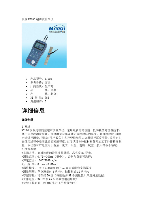
美泰MT160超声波测厚仪∙产品型号:MT160∙参考价格:面议∙厂商性质:生产商∙品牌:美泰∙产地:北京∙3I 指数:768∙典型用户:0详细信息详细介绍1 概述MT160仪器是智能型超声波测厚仪,采用最新的高性能、低功耗微处理器技术,基于超声波测量原理,可以测量金属及其它多种材料的厚度,并可以对材料的声速进行测量。
可以对生产设备中各种管道和压力容器进行厚度测量,监测它们在使用过程中受腐蚀后的减薄程度,也可以对各种板材和各种加工零件作精确测量。
本仪器可广泛应用于石油、化工、冶金、造船、航空、航天等各个领域。
2 技术参数*显示方法:高对比度的段码液晶显示,高亮度EL背光;*测量范围:0.75~300mm(钢中),公制与英制可选择;*声速范围:1000~9999 m/s:*分辨率:0.1mm /0.01mm*示值精度:±(0.5%H+0.04)mm H为被测物实际厚度*测量周期:单点测量时4次/秒、扫描模式10次/秒;*存储容量:可存储20组(每组最多99个测量值)厚度测量数据。
*工作电压:3V(2节AA尺寸碱性电池串联)*持续工作时间:约100小时(不开背光时)*外形尺寸:150×74×32 mm*整机重量:245g3 主要功能*适合测量金属(如钢、铸铁、铝、铜等)、塑料、陶瓷、玻璃、玻璃纤维及其他任何超声波的良导体的厚度;*可配备多种不同频率、不同晶片尺寸的双晶探头使用;*具有探头零点校准、两点校准功能, 可对系统误差进行自动修正;*已知厚度可以反测声速,以提高测量精度;*具有耦合状态提示功能;*有EL背光显示,方便在光线昏暗环境中使用;*有剩余电量指示功能,可实时显示电池剩余电量;*具有自动休眠、自动关机等节电功能;*小巧、便携、可靠性高,适用于恶劣的操作环境,抗振动、冲击和电磁干扰;*带RS232接口,支持现场打印机;4 工作原理本超声波测厚仪对厚度的测量,是由探头产生超声波脉冲透过耦合剂到达被测体,一部分超声信号被物体底面反射,探头接收由被测体底面反射的回波,精确地计算超声波的往返时间,并按下式计算厚度值,再将计算结果显示出来。
SD160
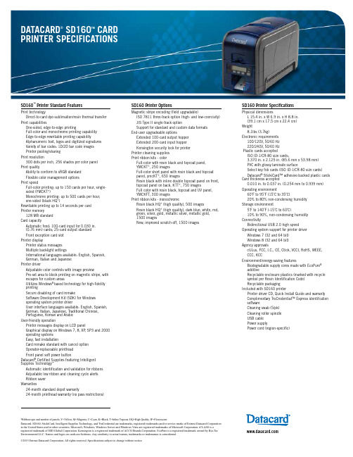
SD160™ Printer Standard FeaturesPrint technologyDirect-to-card dye-sublimation/resin thermal transfer Print capabilitiesO ne-sided, edge-to-edge printingFull-color and monochrome printing capabilityEdge-to-edge rewritable printing capabilityAlphanumeric text, logos and digitized signaturesVariety of bar codes: 1D/2D bar code imagesPrinter pooling/sharingPrint resolution300 dots per inch, 256 shades per color panelPrint qualityAbility to conform to sRGB standardFlexible color management optionsPrint speedFull-color printing: up to 150 cards per hour, single-sided (YMCKT*)Monochrome printing: up to 500 cards per hour,one-sided (black HQ*)Rewritable printing up to 14 seconds per cardPrinter memory128 MB standardCard capacityA utomatic feed: 100-card input for 0.030 in.(0.76 mm) cards; 25-card output standardFront exception card slotPrinter displayPrinter status messagesMultiple backlight settingsInternational languages available: English, Spanish,German, Italian and JapanesePrinter driverAdjustable color controls with image previewP re-set area to block printing on magnetic stripe, with escapes for custom areasU tilizes Windows® based technology for high-fidelityprintingSecure disabling of card remakeS oftware Development Kit (SDK) for Windowsoperating system printer driverUser interface languages available: English, Spanish, German, Italian, Japanese, Traditional Chinese,Portuguese, Korean and ArabicUser-friendly operationP rinter messages display on LCD panelG raphical display on Windows 7, 8, XP, SP3 and 2000operating systemsEasy, fast installationCard remake standard with cancel optionOperator-replaceable printheadFront panel soft power buttonDatacard® Certified Supplies featuring Intelligent Supplies Technology™Automatic identification and validation for ribbonsAdjustable low ribbon and cleaning cycle alertsRibbon saverWarranties24-month standard depot warranty24-month printhead warranty (no pass restrictions)SD160 Printer OptionsMagnetic stripe encoding (field upgradable)ISO 7811 three-track option (high- and low-coercivity)JIS Type II single-track optionSupport for standard and custom data formatsEnd-user upgradeable optionsExtended 100-card output hopperExtended 200-card input hopperKensington security lock for printerPrinter cleaning suppliesPrint ribbon kits - colorFull-color with resin black and topcoat panel,YMCKT*, 250 imagesFull-color short panel with resin black and topcoatpanel, ymcKT*, 650 imagesResin black with inline double topcoat panel on front,topcoat panel on back, KTT*, 750 imagesFull color with resin black, topcoat and UV panel,YMCKFT, 300 imagesPrint ribbon kits - monochromeResin black HQ* (high quality), 500 imagesResin black HQ* (high quality), dark blue, white, red,green, silver, gold, metallic silver, metallic gold,1500 imagesNew, improved scratch-off, 1500 imagesSD160 Printer SpecificationsPhysical dimensionsL 15.4 in. x W 6.9 in. x H 8.8 in.(39.1 cm x 17.5 cm x 22.4 cm)Weight8.1lbs (3.7kg)Electronic requirements100/120V, 50/60 Hz220/240V, 50/60 HzPlastic cards acceptedISO ID-1/CR-80 size cards;3.370 in. x 2.125 in. (85.6 mm x 53.98 mm)PVC with glossy laminate surfaceSelect key fob cards (ISO ID-1/CR-80 size cards)Datacard® StickiCard™ adhesive-backed plastic cardsCard thickness accepted0.010 in. to 0.037 in. (0.254 mm to 0.939 mm)Operating environment60˚F to 95˚F (15˚C to 35˚C)20% to 80% non-condensing humidityStorage environment5˚F to 140˚F (-15˚C to 60˚C)10% to 90%, non-condensing humidityConnectivityBidirectional USB 2.0 high speedOperating system support for printer driverWindows 7 (32 and 64 bit)Windows 8 (32 and 64 bit)Agency approvalscULus, FCC, I.C., CE, Ctick, VCCI, RoHS, WEEE,CCC, KCCEnvironment/energy-saving featuresBiodegradable supply cores made with EcoPure®additiveR ecyclable enclosure plastics (marked with recyclesymbol per Resin Identification Code)Recyclable packagingIncluded with SD160 printerPrinter driver CD, Quick Install Guide and warrantyComplimentary TruCredential™ Express identifcationsoftwareCleaning swab (5/pk)Cleaning roller spindleUSB cablePower supplyPower cord (region-specific)Datacard, SD160, StickiCard, Intelligent Supplies Technology, and TruCredential are trademarks, registered trademarks and/or service marks of Entrust Datacard Corporation in the United States and/or other countries. Microsoft, Windows, Windows Server and Windows Vista are registered trademarks of Microsoft Corporation. iCLASS is a registered trademark of HID Global Corporation. Kensington is a registered trademark of ACCO Brands Corporation. EcoPure is a registered trademark owned by Bio-Tec Environmental LLC. Names and logos on cards are fictitious. Any similarity to actual names, trademarks or tradenames is coincidental.©2015 Entrust Datacard Corporation. All rights reserved. Specifications subject to change without notice.*Ribbon type and number of panels; Y=Yellow, M=Magenta, C=Cyan, K=Black, T=Inline Topcoat, HQ=High Quality, IF=Flourescent.。
派士数控转台技术文件AWUP160技术协议中英文-吴
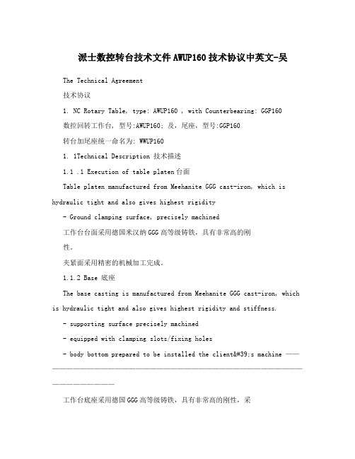
派士数控转台技术文件AWUP160技术协议中英文-吴The Technical Agreement技术协议1. NC Rotary Table, type: AWUP160 , with Counterbearing: GGP160数控回转工作台, 型号:AWUP160; 及,尾座,型号:GGP160转台加尾座统一命名为: WWUP1601. 1Technical Description 技术描述1.1 .1 Execution of table platen台面Table platen manufactured from Meehanite GGG cast-iron, which is hydraulic tight and also gives highest rigidity- Ground clamping surface, precisely machined工作台台面采用德国米汉纳GGG高等级铸铁,具有非常高的刚性。
夹紧面采用精密的机械加工完成。
1.1.2 Base 底座The base casting is manufactured from Meehanite GGG cast-iron, which is hydraulic tight and also gives highest rigidity and stiffness.- supporting surface precisely machined- equipped with clamping slots/fixing holes- body bottom prepared to be installed the client's machine ———————————————————————————————————————————————工作台底座采用德国GGG高等级铸铁,具有非常高的刚性,采用独特的液压夹紧技术具有夹紧速度快,扭矩大,制动性强,平稳性高,抗倾覆力矩强的特点。
DO-160E(部分1)中文版
RTCA Inc1828 L street, NW, Suite 805Washington, DC 20036RTCA/DO-160E机载设备的环境条件和测试程序第22节闪电诱发的瞬态敏感性注意事项:有关测量程序的信息在第1、2、3节。
附录A可以查到实验的环境。
Data of issue: 替代:RTCA/DO-160D 2004年12月9日SC-135制定22.0 闪电诱发的瞬态敏感性……………….………………………………...…22-1 22.1 测试目的……………………………………………………………………22-1 22.2 定义………………………….…………….…………………………..……22-1 22.3 分类………………………….…………….…………………………..……22-2 22.3.1 波形指示(第一、三字符)…………….………………………………22-3 22.3.2 测试等级指示(第二、四和五字符)…………………..………………22-4 22.4 测试的总要求……………………………………………....………………22-4 22.5 测试程序…………….………………………………………….…..………22-8 22.5.1 插针注入测试…………….………………………………………………22-8 22.5.1.1 程序---发生器标定…………….…………………………………...…22-10 22.5.1.2 程序---测试顺序…………….……………………………...…………22-10 22.5.2 电缆束测试…………….……………………………………………..…22-11 22.5.2.1 电缆感应测试…………….…………………………………...………22-12 22.5.2.1.1 程序---发生器性能测试…………….………………………………22-12 22.5.2.1.2 程序---测试顺序…………….………………………………………22-12 22.5.2.2 接地端注入…………….………………….………………………..…22-13 22.5.2.1.1 程序---发生器性能验证…………….………………………………22-13 22.5.2.1.2 程序---测试顺序…………….………………………………………22-14 表格清单:表22-1 测试要求…………….……………………………………..……………22-15 表22-2 插针注入的测试等级……………………………..…….………………22-17 表22-3 电缆束的单次电击响应的测试等级…………………...………………22-17 表22-4电缆束的多次电击响应的测试等级…………….……………...………22-18 表22-5电缆束的多次爆炸响应的测试等级……………………………………22-19 图例清单图22-1 安装图—总体图…………….……………………………….…………22-20 图22-2 电流波形图1…………….……………………………………..………22-20 图22-3 电压波形图2…………….………………….………………….………22-22 图22-4 电压/电流波形图3…………….…………………………..……………22-21图22-5电压波形图4…………….………………………………………………22-22 图22-6电压/电流波形图5…………….…………………….………..…………22-22 图22-7 多次电击条件应用…………….…………………………………..……22-23 图22-8 多次爆炸条件应用…………….……………………………………..…22-23 图22-9 LISN输入阻抗特性…………….………………………………….……22-24 图22-10 单插针的插针注入标定结构图……………………….………………22-25 图22-11 插针注入标定结构图,电源插针-电缆感应法…………….…………22-26 图22-12插针注入标定结构图,电源插针-接地端注入法…………….………22-27 图22-13单插针的插针注入测试结构图…………….…………………………22-28 图22-14插针注入测试结构图,电源插针-电缆感应法…………….…………22-29 图22-15 插针注入测试结构图,电源插针-接地端注入法…………….………22-30 图22-16 电缆感应测试的典型的发生器性能验证结构图…………….………22-31 图22-17 典型的电缆束测试结构图…………….………………………………22-31 图22-18接地端注入测试的典型的发生器性能验证结构图………….….……22-32 图22-19典型的接地端注入测试结构图…………….…………………….……22-3222.0 闪电诱发的瞬态敏感性22.1 测试目的这些测试方法和程序应用理想化的波形来测试设备的承受闪电诱发的电气瞬态的能力。
SMT-钢网印刷资料

SMA Introduce
Mount
AOI
Reflow
Screen Printer
Screen Printer 内部工作图
SMA Introduce
Squeegee
Solder paste
Stencil
STENCIL PRINTING
Screen Printer
SMA Introduce
Screen Printer 的基本要素:
SMA Introduce
菱形刮刀 拖裙形刮刀
聚乙烯材料 或类似材料
金属பைடு நூலகம்
Squeegee Stencil
菱形刮刀
10mm 45度角
Squeegee Stencil
拖裙形刮刀
45-60度角
Screen Printer
SMA Introduce
Squeegee的压力设定:
第一步:在每50mm的Squeegee长度上施加1kg的压力。
Screen Printer
无铅锡膏熔化温度范围:
无铅焊锡化学成份
48Sn/52In 42Sn/58Bi 91Sn/9Zn 93.5Sn/3Sb/2Bi/1.5Cu 95.5Sn/3.5Ag/1Zn 93.3Sn/3.1Ag/3.1Bi/0.5Cu 99.3Sn/0.7Cu 95Sn/5Sb 65Sn/25Ag/10Sb 96.5Sn/3.5Ag 97Sn/2Cu/0.8Sb/0.2Ag
• 减少所印之锡膏厚度 • 提升印着的精准度. • 调整锡膏印刷的参数.
Screen Printer
SMA Introduce
锡膏丝印缺陷分析:
问题及原因
对
策
• 4.膏量不足 INSUFFICIENT PASTE
