SM2E470LC中文资料
SM2算法芯片
SM2算法芯片用户手册(UART接口)注意:用户在实际使用时只需通过UART口控制SM2算法芯片即可,控制协议及使用参考示例见下面QQ:1900109344(算法芯片交流)目录1. 概述 (2)2. 基本特征 (2)3. 通信协议 (2)3.1. 物理层 (2)3.2. 链路层 (3)3.2.1. 通讯数据包定义 (3)3.2.2. 协议描述 (3)3.3. 数据单元格式 (4)3.3.1. 命令单元格式 (4)3.3.2. 应答单元格式 (4)3.4. SM2算法操作指令 (5)3.4.1. SM2_Sign SM2签名 (5)3.4.2. SM2_Verify SM2验证 (5)3.4.3. SM2_Enc SM2加密 (6)3.4.4. SM2_Dec SM2解密 (6)3.5. SM2_GetPairKey 产生SM2密钥对 (7)3.6. SM2算法公钥导入 (7)3.7. 校验/修改Pin指令 (8)3.8. SM2算法使用示例 (9)1.概述本文档适用于使用SM2算法芯片进行终端产品开发的用户。
终端开发者通过Uart口发命令的方式操作SM2算法芯片进行数据交换,产品应用开发。
通过阅读本文档,终端开发者可以在无需考虑算法实现细节情况下,迅速完成产品开发。
2.基本特征芯片的基本特征见下表:串口波特率 115200 bps(默认)供电电源 DC 3.3V,5V通讯接口 UART3.通信协议3.1.物理层SM2算法芯片采用系统供电方式,电压5V或者3.3V。
算法芯片串口与系统MCU串口相连,异步全双工通讯,波特率默认为115200bps。
数据格式为1位起始位、8位数据位和1位停止位,无校验位。
系统MCU向SM2算法芯片发送命令时,在同一个命令内,相连两个发送字符之间的间隔不应大于10个字符时间,否则芯片可能会认为命令超时导致无任何响应。
3.2.链路层3.2.1.通讯数据包定义通信数据包如下图所示:STX(0x02) Len_Hi Len_Low Data LRC ETX(0x03)通讯数据包项目、长度、含义说明对应见下表:通讯数据包项目含义一览表序号 项 目 长度(字节)说明1 数据包头(STX) 1 常量:0x022 数据单元长度(Len) 2 需传输的数据单元Data部分的长度,高字节在前,低字节在后。
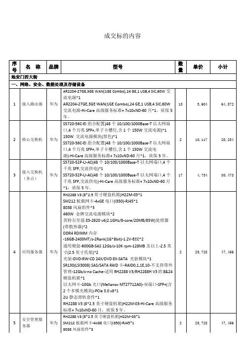
成交标的内容
40,700
40,700
11
网络防病毒软件
360
360天擎终端管理系统:防病毒的病毒查杀引擎包括云查杀引擎、AVE、QEX、QVM等引擎,支持多引擎的协同工作对病毒、木马、恶意软件、引导区病毒、BIOS病毒等进行查杀,提供主动防御系统防护等功能。客户端系统默认支持Windows XP/VISTA/WIN7/WIN8/WIN10,含五年年升级服务;包括20个服务器端授权许可和300个客户端授权许可,质保5年。
"
5
680
3,400
20
高清红外室外球机
大华
DH-SD-6C3230U-HN:"30倍光学变倍,
支持H.265编码,实现超低码流传输
信噪比达到55dB;支持隐私遮挡,最多24块区域,同时最多有8块区域在同一个画面;宽动态效果,加上图像降噪功能,完美的白天/夜晚图像展现
内置150米红外灯补光,采用倍率与红外灯功率匹配算法,补光效果更均匀;支持24V±25%宽电压输入
质保5年。
4
29,962
119,848
7
A类入侵检测系统
华为
NIP6650D交流主机(8GE电+4GE光,2交流电源,含知识库升级服务12个月)*1
300GB 10K RPM SAS硬盘插卡,用于1U机架型网关设备*1
伸缩滑道*1
NIP6650D交流主机(8GE电+4GE光,2交流电源,含知识库升级服务12个月)-Hi-Care高级服务标准+ 7x10xND-60月*1,质保5年。
以太网卡-10Gb光口(Mellanox MT27712A0)-双端口-SFP+(含2个多模光模块)-PCIe 3.0 x8*1
sSpec编号与CPU型号

sSpec编号与CPU型号sSpec编号与CPU型号以及步进编码对应表数码电子2008-12-29 19:12:53 阅读348 评论0 字号:大中小订阅Intel? Core2 Quad Mobile ProcessorsSpec#CPU Speed Processor#Code Name Core s Bus Speed Mfg Tech Stepping Cache Size SLB5G 2.26 GHz Q9100Penryn41066 MHz45 nm E012 MB SLGEJ 2.00 GHz Q9000Penryn41066 MHz45 nm E0 6 MBIntel? Core2 Duo Mobile ProcessorsSpec#CPU Speed Processor#Code Name Core s Bus Speed Mfg Tech Stepping Cache Size SL3BX 2.53 GHz T9400Penryn21066 MHz45 nm C0 6 MB SLB3R 2.26 GHz P8400Penryn21066 MHz45 nm M0 3 MB SLB3S 2.40 GHz P8600Penryn21066 MHz45 nm M0 3 MB SLB43 2.80 GHz T9600Penryn21066 MHz45 nm C0 6 MB SLB46 2.53 GHz T9400Penryn21066 MHz45 nm C0 6 MB SLB47 2.80 GHz T9600Penryn21066 MHz45 nm C0 6 MB SLB4E 2.53 GHz P9500Penryn21066 MHz45 nm C0 6 MB SLB4M 2.26 GHz P8400Penryn21066 MHz45 nm M0 3 MB SLB4N 2.40 GHz P8600Penryn21066 MHz45 nm M0 3 MB SLB53 2.00 GHz P7350Penryn21066 MHz45 nm M0 3 MB SLB63 2.26 GHz SP9300Penryn21066 MHz45 nm C0 6 MB SLB64 2.40 GHz SP9400Penryn21066 MHz45 nm C0 6 MB SLB65 1.60 GHz SL9300Penryn21066 MHz45 nm C0 6 MB SLB66 1.86 GHz SL9400Penryn21066 MHz45 nm C0 6 MB SLG8X 2.00 GHz P7370Penryn21066 MHz45 nm M0 3 MB SLGE4 2.66 GHz T9550Penryn21066 MHz45 nm E0 6 MB SLGE6 2.66 GHz P9600Penryn21066 MHz45 nm E0 6 MB SLGES 2.93 GHzP8700Penryn21066 MHz45 nm M0 3 MB SLA3M 2.40 GHz T7700Merom2800 MHz65 nm E1 4 MB SLA3N 2.20 GHz T7500Merom2800 MHz65 nm E1 4 MB SLA3P 2.00 GHz T7300Merom2800 MHz65 nm E1 4 MB SLA3R 1.60 GHz L7500Merom2800 MHz65 nm L2 4 MB SLA3S 1.40 GHz L7300Merom2800 MHz65 nm E1 4 MB SLA3T 2.00 GHz T7250Merom2800 MHz65 nm M0 2 MB SLA3U 1.80 GHz T7100Merom2800 MHz65 nm M0 2 MB SLA43 2.40 GHz T7700Merom2800 MHz65 nm E1 4 MB SLA44 2.20 GHz T7500Merom2800 MHz65 nm E1 4 MB SLA45 2.00 GHz T7300Merom2800 MHz65 nm E1 4 MBSLA4A 1.80 GHz T7100Merom2800 MHz65 nm M0 2 MB SLA75 2.60 GHz T7800Merom2800 MHz65 nm G0 4 MB SLADL 2.40 GHz T7700Merom2800 MHz65 nm G0 4 MB SLADM 2.20 GHz T7500Merom2800 MHz65 nm G0 4 MB SLAEB 1.60 GHz T5470Merom2800 MHz65 nm M0 2 MB SLAF6 2.60 GHz T7800Merom2800 MHz65 nm G0 4 MB SLAF7 2.40 GHz T7700Merom2800 MHz65 nm G0 4 MB SLAF8 2.20 GHz T7500Merom2800 MHz65 nm G0 4 MB SLAP9 2.10 GHz T8100Penryn2800 MHz45 nm M0 3 MB SLAPA 2.40 GHz T8300Penryn2800 MHz45 nm M0 3 MB SLAPR 2.40 GHz T8300Penryn2800 MHz45 nm M0 3 MB SLAPS 2.10 GHz T8100Penryn2800 MHz45 nm M0 3 MB SLAPT 2.10 GHz T8100Penryn2800 MHz45 nm M0 3 MB SLAPU 2.40 GHz T8300Penryn2800 MHz45 nm C0 3 MB SLAPV 2.50 GHz T9300Penryn2800 MHz45 nm C0 6 MB SLAPW 2.60 GHz T9500Penryn2800 MHz45 nm C0 6 MB SLAQG 2.50 GHz T9300Penryn2800 MHz45 nm C0 6 MB SLAQH 2.60 GHz T9500Penryn2800 MHz45 nm C0 6 MB SLAUU 2.10 GHzT8100Penryn2800 MHz45 nm M0 3 MB SLAX G 2.10 GHz T8100Penryn2800 MHz45 nm M0 3 MB SLAYP 2.10 GHz T8100Penryn2800 MHz45 nm M0 3 MB SLAYQ 2.40 GHz T8300Penryn2800 MHz45 nm M0 3 MB SLAYX 2.60 GHz T9500Penryn2800 MHz45 nm C0 6 MB SLAYY 2.50 GHz T9300Penryn2800 MHz45 nm C0 6 MB SLAYZ 2.10 GHz T8100Penryn2800 MHz45 nm M0 3 MB SLAZA 2.60 GHz T9500Penryn2800 MHz45 nm C0 6 MB SLAZB 2.50 GHz T9300Penryn2800 MHz45 nm C0 6 MB SLAZC 2.40 GHz T8300Penryn2800 MHz45 nm M0 3 MB SLAZD 2.10 GHz T8100Penryn2800 MHz45 nm M0 3 MB SLB5Q 1.20 GHz SU9300Penryn2800 MHz45 nm M0 3 MB SLB6E 2.00 GHz T5800Merom2800 MHz65 nm M0 2 MB SLGHN 1.40 GHz SU9400Penryn2800 MHz45 nm M0 3 MB SL9SD 2.33 GHz T7600Merom2667 MHz65 nm B2 4 MB SL9SE 2.16 GHz T7400Merom2667 MHz65 nm B2 4 MB SL9SF 2.00 GHz T7200Merom2667 MHz65 nm B2 4 MB SL9SG 1.83 GHz T5600Merom2667 MHz65 nm B2 2 MB SL9SH 1.66 GHz T5500Merom2667 MHz65 nm B2 2 MB SL9SJ 2.33 GHz T7600Merom2667 MHz65 nm B2 4 MBSL9SL 2.00 GHz T7200Merom2667 MHz65 nm B2 4 MBSL9SM 1.50 GHz L7400Merom2667 MHz65 nm B2 4 MBSL9SN 1.33 GHz L7200Merom2667 MHz65 nm B2 4 MBSL9SP 1.83 GHz T5600Merom2667 MHz65 nm B2 2 MBSL9SQ 1.66 GHz T5500Merom2667 MHz65 nm B2 2 MB SL9U3 1.83 GHz T5600Merom2667 MHz65 nm L2 2 MB SL9U4 1.66 GHz T5500Merom2667 MHz65 nm L2 2 MB SL9U7 1.83 GHz T5600Merom2667 MHz65 nm L2 2 MB SL9U8 1.66 GHz T5500Merom2667 MHz65 nm L2 2 MB SLA4D 2.00 GHzT5750Merom2667 MHz65 nm M0 2 MB SLA4E 1.83 GHz T5550Merom2667 MHz65 nm M0 2 MB SLA4F 1.66 GHz T5450Merom2667 MHz65 nm M0 2 MB SLA9S 1.50 GHz T5250Merom2667 MHz65 nm M0 2 MBSL9VP 1.60 GHz T5200Merom2533 MHz65 nm B2 2 MBSL9WE 1.73 GHz T5300Merom2533 MHz65 nm L2 2 MB SLA2U 1.20 GHz U7600Merom2533 MHz65 nm L2 2 MB SLA2V 1.06 GHz U7500Merom2533 MHz65 nm L2 2 MB SLV3W 1.33 GHz U7600Merom2533 MHz65 nm M0 2 MB SLV3X 1.20 GHz U7500Merom2533 MHz65 nm M0 2 MBIntel? Pentium? Dual-Core Mobile ProcessorsSpec# CPU Speed Processor#Code Name Core s Bus Speed Mfg Tech Stepping Cache Size SLAVG 2.00 GHz T3200Merom2667 MHz65 nm M0 1 MB SLA4H 1.86 GHz T2390Merom2533 MHz65 nm M0 1 MB SLA4J 1.73 GHz T2370Merom2533 MHz65 nm M0 1 MB SLA4K 1.60 GHz T2330Merom2533 MHz65 nm M0 1 MB SLAEC 1.46 GHz T2310Merom2533 MHz65 nm M0 1 MB SL9VZ 1.86 GHz T2130Merom2533 MHz65 nm D0 1 MBSL9VY 1.73 GHz T2080Merom2533 MHz65 nm D0 1 MBSL9VX 1.60 GHz T2060Merom2533 MHz65 nm D0 1 MBIntel? Celeron? Mobile ProcessorsSpec# CPU Speed Processor#Code Name Core s Bus Speed Mfg Tech Stepping Cache Size SLGAS 1.20 GHz723N/A2800 MHz45 nm M0 1 MB SLB6J 1.66 GHz T1600Merom2667 MHz65 nm M0 1 MB SLB6H 1.83 GHz T1700Merom2667 MHz65 nm M0 1 MB SLB6M 2.00 GHz575Conroe L1667 MHz65 nm M0 1 MB SLB6L 2.16 GHz585Conroe L1667 MHz65 nm M0 1 MB SL8X W 1.06 GHz423Conroe L1533 MHz65 nm C0 1 MBSL9L8 1.20 GHz443Conroe L1533 MHz65 nm D0 1 MBSL8W2 1.46 GHz410Conroe L1533 MHz65 nm C0 1 MBSL9WN 1.60 GHz520Conroe L1533 MHz65 nm A1 1 MB SL8VZ 1.60 GHz420Conroe L1533 MHz N/A C0 1 MB SL9WT 1.60 GHz520Conroe L1533 MHz65 nm B2 1 MB SL92F 1.73 GHz430Conroe L1533 MHz65 nm C0 1 MB SLA2G 1.73 GHz530Conroe L1533 MHz65 nm A1 1 MBSL9KV 1.73 GHz430Conroe L1533 MHz65 nm D0 1 MBSL9VA 1.73 GHz530Conroe L1533 MHz65 nm A1 1 MB SLA2F 1.86 GHz540Conroe L1533 MHz65 nm A1 1 MBSL9KW 1.86 GHz440Conroe L1533 MHz65 nm D0 1 MB SLA2E 2.00 GHz550Conroe L1533 MHz65 nm A1 1 MB SL9KX 2.00 GHz450Conroe L1533 MHz65 nm D0 1 MB SLA2D 2.13 GHz560Conroe L1533 MHz65 nm A1 1 MB Intel? Atom ProcessorsSpec# CPU Speed Processor#Code Name Core s Bus Speed Mfg Tech Stepping Cache Size SLB2H 1.33 GHz Z520Silverthorne1533 MHz45 nm C0512 KB SLG9Y 1.60 GHz330N/A2533 MHz45 nm C0 1 MB SLB73 1.60 GHz N270Silverthorne1533 MHz45 nm C0512 KB SLB6Z 1.60 GHz230Silverthorne1533 MHz45 nm C0512 KB SLB6P 1.60 GHz Z530Silverthorne1533 MHz45 nm C0512 KB SLB2M 1.86 GHz Z540Silverthorne1533 MHz45 nm C0512 KB SLB6Q800 MHz Z500Silverthorne1400 MHz45 nm C0512 KB SLB2C 1.10 GHz Z510Silverthorne1400 MHz45 nm C0512 KB。
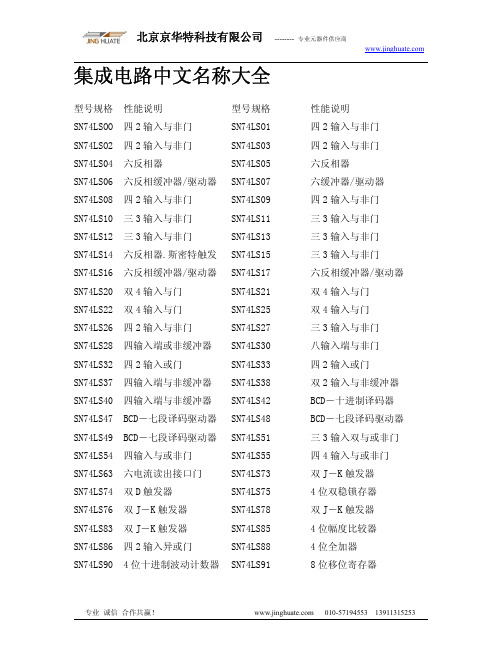
集成电路IC芯片中文名称大全
专业 诚信 合作共赢!
010-57194553 13911315253
北京京华特科技有限公司 -------- 专业元器件供应商
SN7407 六缓冲器/驱动器
SN74HC03
SN7414 六缓冲器/驱动器
SN74HC04
SN7416 六反相缓冲器/驱动器 SN74HC05
SN74LS126
SN74LS133 13 输入与非门
SN74LS132
SN74LS137 地址锁存 3-8 线译码器 SN74LS136
SN74LS139 双 2-4 线译码-转换器 SN74LS138
SN74LS147 10-4 线优先编码器 SN74LS145
SN74LS153 双 4 选 1 数据选择器 SN74LS148
专业 诚信 合作共赢!
010-57194553 13911315253
北京京华特科技有限公司 -------- 专业元器件供应商
SN74LS92 12 分频计数器
SN74LS93
SN74LS96 5 位移位寄存器
SN74LS95
SN74LS273
SN74LS283 4 位二进制全加器
SN74LS276
SN74LS293 4 位二进制计数器
SN74LS280
SN74LS365 六缓冲器带公用启动器 SN74LS290
SN74LS367 六总线三态输出缓冲器 SN74LS295
SN74LS373 8D 锁存器 SN74LS375 4 位双稳锁存器 SN74LS386 四 2 输入异或门 SN74LS393 双 4 位二进制计数器 SN74LS574 8 位 D 型触发器
SN74LS155 双 2-4 线多路分配器 SN74LS151
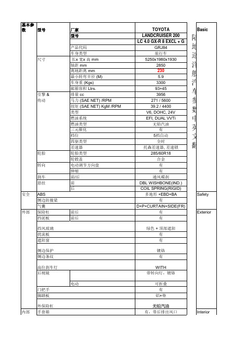
LC 4.0 GXR 陆地巡洋舰进口车参数中英文对照翻译
MAKE MODEL NAME
SEAT MATERIAL Fr. SEAT
Rr. SEAT
Fr. SEAT BELT POWER SEAT LUMBER SUPPORT VERTICAL SEAT ADJUSTER Rr. SEAT BELT HEAD REST SPLIT FOLDABLE SEAT CENTRE ARMREST 3RD ROW
FABRIC 3PELRx2+PT+FL WITH (DRIVER) WITH WITH 3PELRx6 3 (2nd ROW)+3 (3 ROW) 60:40+RECLINING +SLIDE WITHOUT 50:50 TRANSVERSE WITH WITHOUT WITH DAY/NIGHT D+P D+P WITH ILLUMINATION 8 INTERMITTENT INTERMITTENT WITH WITH SMART ENTRY +PUSH START ELECTRICAL WITH WITHOUT WITH+SCUFF PLATE ILLUM. AM/FM 9" DA,CD /MP3,USB,AUX,BT 6 SPK GLASS INTEGRATED WITH FR AUTO, RR MAN/WITH WITH WITH (FF+RR)* BI LED2+3 (LOW) + HALOGEN (HIGH) WITHOUT WITHOUT WITH (1-WAY TYPE INCORPORATED ENGINE IN KEY) IMMOBILISER+ALARM WITH * WITH LIFT UP TYPE WITH FLOOR +DOOR MOUNTED/HARD CHROME+SILVER WITH WITH WITH CHROME WITH
TPS24700 01 10 11 EVM 用户指南说明书
TPS24700EVM-001TPS24701EVM-002Using the TPS24700EVM-001,TPS24701EVM-002,TPS24710EVM-003and the TPS24711EVM-004User's GuideLiterature Number:SLUU459January2011User's GuideSLUU459–January2011 TPS24700/01/10/11Evaluation Module(TPS24700EVM-001, TPS24701EVM-002,TPS24710EVM-003and theTPS24711EVM-004)This User’s Guide describes the setup and operation of the TPS24700EVM-001,TPS24701EVM-002, TPS24710EVM-003and the TPS24711EVM-004system test boards.1IntroductionThis User’s Guide describes the features of the TPS24700/01/10/11EVM.Also provided are theschematic,layout and list of materials.2DescriptionThe EVM is a3-V to20-V module using the TPS24700/01/10/11hot-swap controller with externalMOSFET.At power on,the output is power limited to control inrush current and protect the MOSFET.On an over-current condition,the controller interrupts power to the load at high speed and signals load status.Operating current,fault current and fault timer settings are hardware programmable.2.1Applications•Server–Plug-In Circuit Boards–RAID/Disk Drive•Telecom–ATCA–Micro-ATCA•General Hot Plug2.2Features•Board design covers input/output from3-V to20-V but is factory set for12-V operation.The customer can change components to operate at other voltages and currents.•Board design for50-A steady state max output.The EVM will be set up for a12-V,25-A nominal application.The datasheet design examples show how to select components for other operating setpoints.•Latch-off or re-try controller by part number.•Input/output out of operating range transient voltage protections.•Support components to be0603size where permitted by power dissipation or component ratings.•2-oz copper,4layer.•On-board ENABLE input(slide switch).2TPS24700/01/10/11Evaluation Module(TPS24700EVM-001,SLUU459–January2011 TPS24701EVM-002,TPS24710EVM-003and the TPS24711EVM-004)Submit Documentation Feedback©2011,Texas Instruments Incorporated Schematic3SchematicFigure 1.3SLUU459–January 2011TPS24700/01/10/11Evaluation Module (TPS24700EVM-001,TPS24701EVM-002,TPS24710EVM-003and the TPS24711EVM-004)Submit Documentation Feedback©2011,Texas Instruments IncorporatedOvervoltage Protection 4Overvoltage ProtectionInput protection for the TPS24700A and MOSFET consists of a15-V TVS and0.1-µF and47-µFcapacitors located close to the VIN pins.The TVS is active at16.5V S is Vishay SMAJ15A,400W,SMA package.Output protection is a fixed47-µF capacitor and a parallel0.1-µF capacitor located at the output terminals.A schottky diode on the output clamps negative going transitions.Diode MBRS3100T3,3A,100V.5ENABLE SignalSlide switch to operate ENABLE signal.The Enable signal is externally pulled to VIN through a resistor divider to set the UV to10-V.A0.1-µF capacitor will be used to help de-bounce the Enable switch.6Test PointsTest points are located on the board edge.Table1.Test PointsNAME DESCRIPTIONENUV Enable Signal4.3-V REF 4.3VPG Power Good,Signal,Low TrueFLT Fault,Signal,Low TrueSENSE Sense Resistor Voltage LowGND Scope Ground Test PointGND Scope Ground Test PointGND Scope Ground Test PointGND Scope Ground Test PointVOUT Output VoltageCT Fault Timer CapacitorPROG Program VoltageSET Current Limit Set PointGATE Gate SignalVIN Input Voltage Power Supply4TPS24700/01/10/11Evaluation Module(TPS24700EVM-001,SLUU459–January2011 TPS24701EVM-002,TPS24710EVM-003and the TPS24711EVM-004)Submit Documentation Feedback©2011,Texas Instruments Incorporated Jumpers 7JumpersNone8Indicator LEDSA4.3-V Zener is used to control the voltage applied to the EN signal.It is also used to limit the voltage range on the LEDs.A bipolar signal transistor is used to turn on the LED while keeping the PG and FLT signals less than0.3-V active.Table2.Indicator LED ColorsSIGNAL LED COLORPG GreenFLT Red9Disable Power LimitingPower limiting can be disabled by leaving the PROG pin open(no programming resistor).The soft-start time can be controlled by a gate capacitor and series1-kΩresistor.See Not Installed.10Not Installed•D6is installed if the VGS needs to be limited.The zener voltage rating set VGS max.•R19,C9installed if the soft start is not controlled by power limiting but by gate current and the selected C9Where C=I x T/V.Example,for10-ms start on a12-V board,C=30µA x10ms/25V,C=12nF.5 SLUU459–January2011TPS24700/01/10/11Evaluation Module(TPS24700EVM-001,TPS24701EVM-002,TPS24710EVM-003and the TPS24711EVM-004) Submit Documentation Feedback©2011,Texas Instruments IncorporatedEVM Assembly Drawings and Layout 11EVM Assembly Drawings and LayoutFigure2.Board Topyer16TPS24700/01/10/11Evaluation Module(TPS24700EVM-001,SLUU459–January2011 TPS24701EVM-002,TPS24710EVM-003and the TPS24711EVM-004)Submit Documentation Feedback©2011,Texas Instruments Incorporated EVM Assembly Drawings and Layoutyer2Figure5.Board Bottom7 SLUU459–January2011TPS24700/01/10/11Evaluation Module(TPS24700EVM-001,TPS24701EVM-002,TPS24710EVM-003and the TPS24711EVM-004) Submit Documentation Feedback©2011,Texas Instruments IncorporatedList of Materials 12List of MaterialsTable3.List of Materials(1)(2)(3)(4)REF-004-003-002-001DESCRIPTION PART NUMBER MFRDESC1,C6,Capacitor,ceramic,100V,X7R,10%,0.1µF,STD STD 4444C7,C80805C9Capacitor,ceramic,100V,X7R,10%,0.1µF,STD STD 00000805C2Capacitor,ceramic,100V,X7R,10%,1000pF,STD STD 11110603C3,C5Capacitor,aluminum,80VDC,±20%,68µF,EEVFK1K680Q Panasonic 22220.670inch x0.750inchC4Capacitor,ceramic,16V,X7R,10%,68nF,STD STD 111106031111D1Diode,[uni-]directional TVS,1500W,SMC SMCJ18A-13-F Diodes1111D2Diode,Zener,4.3V,SOT23MMBZ5229B Motorola1111D3Diode,Schottky,3A,40V,SMC MBRS330T3G On Semi1111D4Diode,LED,green,0.114inch x0.049inch LN1371G PanasonicD5Diode,LED,ultra bright red,0.114inch x0.049LN1271RAL Panasonic 1111inchD6Diode,Zener,planar power,500mW,8.2V,BZT52C8V2-7Vishay 0000SOD-123J1,J2,Lug,copper,35A,0.380inch x1.020inch CX35-36Panduit 4444J3,J4Q1,Q2MOSFET,N-channel,25V,37A,1.3mΩ,QFN CSD16401Q5A-R Ciclon 22225x6mm2222Q3,Q4Bipolar,PNP,40V,200mA,SOT23MMBT3906LT1On Semi1111R1Resistor,chip,1/16W,1%,133kΩ,0603STD STDR11,Resistor,chip,1/16W,5%,10kΩ,0603STD STD 2222R15R12,Resistor,chip,1/16W,5%,20kΩ,0603STD STD 2222R16R13,Resistor,chip,1/16W,1%,1kΩ,0603STD STD 2222R170000R19Resistor,chip,1/16W,1%,1kΩ,0603STD STDR14,Resistor,chip,1/10W,5%,300Ω,0805STD STD 2222R181111R2Resistor,chip,1/16W,1%,22kΩ,0603STD STD1100R3Resistor,chip,1/16W,1%,75kΩ,0603STD STDR4Resistor,metal strip,0.01Ohms,2W,1%,0.01LCR-LRF2512-IRC 0000Ω,251201-R010-FR5Resistor,power metal strip,3W,±x1%,0.001Ω,WSR-3Vishay Dale 111145271111R8Resistor,chip,0.5W,1%,499Ω,2512STD STD2222R9,R10Resistor,chip,1/16W,1%,10Ω,0603Std Std(1)These assemblies are ESD sensitive,ESD precautions shall be observed.(2)These assemblies must be clean and free from flux and all e of no clean flux is not acceptable.(3)These assemblies must comply with workmanship standards IPC-A-610Class2.(4)Ref designators marked with an asterisk('**')cannot be substituted.All other components can be substituted with equivalentMFG's components.8TPS24700/01/10/11Evaluation Module(TPS24700EVM-001,SLUU459–January2011 TPS24701EVM-002,TPS24710EVM-003and the TPS24711EVM-004)Submit Documentation Feedback©2011,Texas Instruments Incorporated List of MaterialsTable3.List of Materials(1)(2)(3)(4)(continued)REF-004-003-002-001DESCRIPTION PART NUMBER MFRDESS1Switch,SPDT,slide,PC mount,500mA,0.40009.03201.02EAO 1111inch x0.100inchTP1,Test point,white,thru hole,0.125inch x0.1255012KeystoneTP2,inchTP3,TP4,TP5,TP6,TP7,14141414TP8,TP9,TP10,TP11,TP12,TP13,TP14U1 2.5V to20V Positive Voltage Power-Limiting TPS24700DGK TI 0001Hotswap Controller,VSSOP-8U1 2.5V to20V Positive Voltage Power-Limiting TPS24701DGK TI 0010Hotswap Controller,VSSOP-8U2 2.5V to20V Positive Voltage Power-Limiting TPS24710DGS TI 0100Hotswap Controller,VSSOP-10U2 2.5to20V Positive Voltage Power-Limiting TPS24711DGS TI 1000Hotswap Controller,VSSOP-101111--PCB,4.82inch x3.3inch x0.062inch PCB Any4444Bumpons,cylindrical,black SJ5514-03M4444Screw,panhead#10-320.500inch4444Washer,flat#104444Washer,split M54444Nut,hex#10-329 SLUU459–January2011TPS24700/01/10/11Evaluation Module(TPS24700EVM-001,TPS24701EVM-002,TPS24710EVM-003and the TPS24711EVM-004) Submit Documentation Feedback©2011,Texas Instruments IncorporatedEvaluation Board/Kit Important NoticeTexas Instruments(TI)provides the enclosed product(s)under the following conditions:This evaluation board/kit is intended for use for ENGINEERING DEVELOPMENT,DEMONSTRATION,OR EVALUATION PURPOSES ONLY and is not considered by TI to be a finished end-product fit for general consumer use.Persons handling the product(s)must have electronics training and observe good engineering practice standards.As such,the goods being provided are not intended to be complete in terms of required design-,marketing-,and/or manufacturing-related protective considerations, including product safety and environmental measures typically found in end products that incorporate such semiconductor components or circuit boards.This evaluation board/kit does not fall within the scope of the European Union directives regarding electromagnetic compatibility,restricted substances(RoHS),recycling(WEEE),FCC,CE or UL,and therefore may not meet the technical requirements of these directives or other related directives.Should this evaluation board/kit not meet the specifications indicated in the User’s Guide,the board/kit may be returned within30 days from the date of delivery for a full refund.THE FOREGOING WARRANTY IS THE EXCLUSIVE WARRANTY MADE BY SELLER TO BUYER AND IS IN LIEU OF ALL OTHER WARRANTIES,EXPRESSED,IMPLIED,OR STATUTORY,INCLUDING ANY WARRANTY OF MERCHANTABILITY OR FITNESS FOR ANY PARTICULAR PURPOSE.The user assumes all responsibility and liability for proper and safe handling of the goods.Further,the user indemnifies TI from all claims arising from the handling or use of the goods.Due to the open construction of the product,it is the user’s responsibility to take any and all appropriate precautions with regard to electrostatic discharge.EXCEPT TO THE EXTENT OF THE INDEMNITY SET FORTH ABOVE,NEITHER PARTY SHALL BE LIABLE TO THE OTHER FOR ANY INDIRECT,SPECIAL,INCIDENTAL,OR CONSEQUENTIAL DAMAGES.TI currently deals with a variety of customers for products,and therefore our arrangement with the user is not exclusive.TI assumes no liability for applications assistance,customer product design,software performance,or infringement of patents or services described herein.Please read the User’s Guide and,specifically,the Warnings and Restrictions notice in the User’s Guide prior to handling the product.This notice contains important safety information about temperatures and voltages.For additional information on TI’s environmental and/or safety programs,please contact the TI application engineer or visit /esh.No license is granted under any patent right or other intellectual property right of TI covering or relating to any machine,process,or combination in which such TI products or services might be or are used.FCC WarningThis evaluation board/kit is intended for use for ENGINEERING DEVELOPMENT,DEMONSTRATION,OR EVALUATION PURPOSES ONLY and is not considered by TI to be a finished end-product fit for general consumer use.It generates,uses,and can radiate radio frequency energy and has not been tested for compliance with the limits of computing devices pursuant to part15 of FCC rules,which are designed to provide reasonable protection against radio frequency interference.Operation of this equipment in other environments may cause interference with radio communications,in which case the user at his own expense will be required to take whatever measures may be required to correct this interference.EVM Warnings and RestrictionsIt is important to operate this EVM within the input voltage range of3V to20V and the output voltage range of3V to20V. Exceeding the specified input range may cause unexpected operation and/or irreversible damage to the EVM.If there are questions concerning the input range,please contact a TI field representative prior to connecting the input power.Applying loads outside of the specified output range may result in unintended operation and/or possible permanent damage to the EVM.Please consult the EVM User's Guide prior to connecting any load to the EVM output.If there is uncertainty as to the load specification,please contact a TI field representative.During normal operation,some circuit components may have case temperatures greater than50°C.The EVM is designed to operate properly with certain components above50°C as long as the input and output ranges are maintained.These components include but are not limited to linear regulators,switching transistors,pass transistors,and current sense resistors.These types of devices can be identified using the EVM schematic located in the EVM User's Guide.When placing measurement probes near these devices during operation,please be aware that these devices may be very warm to the touch.Mailing Address:Texas Instruments,Post Office Box655303,Dallas,Texas75265Copyright©2011,Texas Instruments IncorporatedIMPORTANT NOTICETexas Instruments Incorporated and its subsidiaries(TI)reserve the right to make corrections,modifications,enhancements,improvements, and other changes to its products and services at any time and to discontinue any product or service without notice.Customers should obtain the latest relevant information before placing orders and should verify that such information is current and complete.All products are sold subject to TI’s terms and conditions of sale supplied at the time of order acknowledgment.TI warrants performance of its hardware products to the specifications applicable at the time of sale in accordance with TI’s standard warranty.Testing and other quality control techniques are used to the extent TI deems necessary to support this warranty.Except where mandated by government requirements,testing of all parameters of each product is not necessarily performed.TI assumes no liability for applications assistance or customer product design.Customers are responsible for their products and applications using TI components.To minimize the risks associated with customer products and applications,customers should provide adequate design and operating safeguards.TI does not warrant or represent that any license,either express or implied,is granted under any TI patent right,copyright,mask work right, or other TI intellectual property right relating to any combination,machine,or process in which TI products or services are rmation published by TI regarding third-party products or services does not constitute a license from TI to use such products or services or a warranty or endorsement e of such information may require a license from a third party under the patents or other intellectual property of the third party,or a license from TI under the patents or other intellectual property of TI.Reproduction of TI information in TI data books or data sheets is permissible only if reproduction is without alteration and is accompanied by all associated warranties,conditions,limitations,and notices.Reproduction of this information with alteration is an unfair and deceptive business practice.TI is not responsible or liable for such altered rmation of third parties may be subject to additional restrictions.Resale of TI products or services with statements different from or beyond the parameters stated by TI for that product or service voids all express and any implied warranties for the associated TI product or service and is an unfair and deceptive business practice.TI is not responsible or liable for any such statements.TI products are not authorized for use in safety-critical applications(such as life support)where a failure of the TI product would reasonably be expected to cause severe personal injury or death,unless officers of the parties have executed an agreement specifically governing such use.Buyers represent that they have all necessary expertise in the safety and regulatory ramifications of their applications,and acknowledge and agree that they are solely responsible for all legal,regulatory and safety-related requirements concerning their products and any use of TI products in such safety-critical applications,notwithstanding any applications-related information or support that may be provided by TI.Further,Buyers must fully indemnify TI and its representatives against any damages arising out of the use of TI products in such safety-critical applications.TI products are neither designed nor intended for use in military/aerospace applications or environments unless the TI products are specifically designated by TI as military-grade or"enhanced plastic."Only products designated by TI as military-grade meet military specifications.Buyers acknowledge and agree that any such use of TI products which TI has not designated as military-grade is solely at the Buyer's risk,and that they are solely responsible for compliance with all legal and regulatory requirements in connection with such use. TI products are neither designed nor intended for use in automotive applications or environments unless the specific TI products are designated by TI as compliant with ISO/TS16949requirements.Buyers acknowledge and agree that,if they use any non-designated products in automotive applications,TI will not be responsible for any failure to meet such requirements.Following are URLs where you can obtain information on other Texas Instruments products and application solutions:Products ApplicationsAudio /audio Communications and Telecom /communicationsAmplifiers Computers and Peripherals /computersData Converters Consumer Electronics /consumer-appsDLP®Products Energy and Lighting /energyDSP Industrial /industrialClocks and Timers /clocks Medical /medicalInterface Security /securityLogic Space,Avionics and Defense /space-avionics-defense Power Mgmt Transportation and /automotiveAutomotiveMicrocontrollers Video and Imaging /videoRFID Wireless /wireless-appsRF/IF and ZigBee®Solutions /lprfTI E2E Community Home Page Mailing Address:Texas Instruments,Post Office Box655303,Dallas,Texas75265Copyright©2011,Texas Instruments IncorporatedTPS24700EVM-001TPS24701EVM-002。
恒银机具
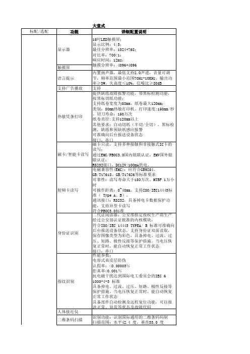
审计
监控系统
报警系统 广告灯箱
主控制系统
现金循环机芯
钞票识别能力 加钞方式 网络接口 密码锁组件 防窥屏
UPS
维护功能
清机管理 系统诊断 系统配置 日常维护 日志操作 使用帮助 整机尺寸 重量 运行环境 通讯
定制菜单功能
输入电压范围:162-286Vac; 输入频率范围:40Hz; 输出电压范围:220Vac+10%(电池模式); 输出频率范围:50+1Hz(电池模式); 输出电压波形:方波。 支持 支持 支持 支持 支持 支持 支持
100M/1000M以太网卡支持TCP/IP协议 输入具有过欠压保护,过流保护; 输出具有过欠压保护、过流保护、短路保护 及过温保护等功能; 整机基本指标 输入电压范围:90~286VAC; 用电要求 输入频率范围:47~63Hz; 具备分级启动控制; 具备断电重启控制; 输入直流电压220VDC; 输出12VDC及24VDC。 电磁兼容性 满足国标标准。 保险柜 保险柜公安部检验报告 整机 PBOC3.0 level2检测报告 整机 EMV2000 level2认证 整机 整机公安部检验报告(GB/T18789.1-2013) 磁卡/智能卡读卡 PBOC3.0 level1检测报告/EMV2000 level1认 器 证 非接触IC卡读卡器PBOC3.0检测报告 安全及产品认证 射频卡读写 身份证识别 二代身份证阅读器相关证书及检测报告 密码键盘PCI认证证书/密码键盘PCI 4.0认证 加密键盘 /密码键盘银联卡受理终端产品安全认证/密 码键盘商用密码产品型号证书 国密算法 商用密码产品销售许可证 国密算法 商用密码产品生产定点单位证书
设备功能
设备功能
发卡
存折补登机加密键盘磁卡只读,支持多种接触和非接触式IC卡的 读写; 通过EMC/PBOC3.0国内银联认证,EMV国外银 联认证; RS232接口,DC12V/100mA供电。 水平吸入式磁条读写方式,并可用于存折打 印,自动纠偏、自动矫正、自动对齐、自动 调整打印厚度、平推、自动进折;支持打印 存折最大宽度为245mm。 打印头 ≥24针机械式打印头,并且可更换打 印头单针寿命达到6亿次以上;支持断针补 偿,支持打印头过热自动降速保护 打印字体:汉字字体:,内设GB18030标准字 库,并具有银行及其他行业所需的各种特殊 符号 字符放大,黑体,斜体,中空,上标,下标, 旋转,反白,上划线,下划线 打印速度:ASCⅡ文字≥400字/秒(高速); 汉字≥268字/秒(高速),信函体≥130字/ 通过银联认证,支持DES,3DES算法,防尘, 防暴; 按键寿命:2000000次,可扩展2片4键功能 键; 通讯类型:串口; MTBF>20000H; MTTR<30min; 符合HDT标准规范,支持HDT摄像机与模拟摄 像机自适应接入; 支持4路高清720P全实时或1080P非全实时编 码; 支持HDMI与VGA同时输出,分辨率最高可达 1920*1080P; 支持4路同步回放; 1个RJ45 10M/100M自适应以太网口; 满足 满足 英特尔凌动双核,低功耗无风扇设计; 配备6个USB口,6个COM口; 配置1个1000Mbps自适应网口; 双核1.86GHZ 四线程; 内存DDR3 2GB; 硬盘500GB 大容量钞箱,循环钞箱容量3000张,可配钞 箱数最多4个(含1个只存/回收钞箱、3个可 配置的存取款循环钞箱); 自动计数功能,能够确定每个钞箱的纸币张 数,提高后期记账及配钞工作的效率; 支持第五套人民币15版100元,05版100元、 50元、20元、10元,99版100元、50元、20元 、10元,第四套人民币100元、50元、10元; 单笔出钞张数最大值200张,验钞模块采用多 种伪钞鉴别技术和手段,能识别各种伪钞、 验钞识别速度8张/秒,出/存钞速度为8张/ 秒; 整叠入钞,整叠出钞 网卡:一个,100M/1000M以太网卡支持 TCP/IP协议,以及银行要求的所有接口。 配备分离式机械钥匙及机械密码锁,密码可 调。 3M防窥膜
卓亚电力 SMG2000E 数字双钳相位伏安表 产品说明书(手册)

SMG2000E数字双钳相位伏安表产品说明书(手册)武汉卓亚电力自动化有限责任公司WHHAN ZHUOYA ELECTRIC POWER AUTOMATION CO.,LTD企业官网: 联系电话:************声明版权所有© 2020武汉卓亚电力自动化有限责任公司本使用说明书所提及的商标与名称,均属于其合法注册公司所有。
本说明书受著作权保护,所撰写的内容均为卓亚电力公司所有。
本使用说明书所提及的产品规格或相关参数,未经许可,任何单位或个人不得擅自仿制、复制、修改、传播或出版。
本使用说明书所提到的产品规格和资讯仅供参考,如有内容更新,恕不另行通知。
可随时查阅官方网站:。
本使用说明书仅作为产品使用指导,所有陈述、信息等均不构成任何形式的担保。
服务承诺感谢您使用卓亚电力公司的产品。
在您初次使用该仪器前,以便正确使用仪器,请您详细阅读此使用说明书,充分发挥其功能,并确保仪器及人身安全。
我们深信优质、系统、全面、快捷的服务是事业发展的基础。
经过多年的不断探索和进取,我们形成了“重质量、重客户"的服务理念。
以更好的产品质量,更完善的售后服务,全力打造技术领先、质量领先、服务领先的电力试验产品品牌企业。
为客户提供满意的售前、售中及售后服务!安全要求为了避免可能发生的危险,请阅读下列安全注意事项。
本产品请使用我公司标配的附件。
防止火灾或电击危险,确保人生安全。
在使用本产品进行试验之前,请务必详细阅读产品使用说明书,按照产品规定试验环境和参数标准进行试验。
2使用产品配套的保险丝。
只可使用符合本产品规定类型和额定值的保险丝。
产品输入输出端子、测试柱等均有可能带电压,试验过程中在插拔测试线、电源插座时,会产生电火花,请务必注意人身安全!请勿在仪器无前(后)盖板的情况下操作仪器/仪表。
试验前,为了防止电击,接地导体必须与真实的接地线相连,确保产品正确接地。
试验中,测试导线与带电端子连接时,请勿随意连接或断开测试导线。
E-Chain系列产品说明书

Features & BenefitsDirt-repellent contoured exteriorCable-friendly, smooth interior with modularinterior separationLateral glide surfaces for side mounted operationLarge pins for long service lifeDouble stop dog for long unsupported lengthTapered insertion point for easy assemblyIntergrated strain relief possibleSnap-open, hinged to left or right, accessible fromSeries 240 snap-open along the inner radius canbe combined with Series 250 snap-open alongthe outer radiusEasy to assemble and disassembleOther Installation MethodsE-Chain System ® E2 Medium Series 200/240/250Installation DimensionsLong Travels -Gliding®200240250Legend.98P D F : w w w .i g u s .c o m /e -c h a i n -p d f s S p e c s /C A D /R F Q : w w w .i g u s .c o m /e -c h a i n s R o H S i n f o : w w w .i g u s .c o m /R o H S4.178If the unsupported lengthis exceeded, the E-Chain ®/Tube must glide on itself. This requires a guide trough.Design, Chapter 1Details of material properties³ Chapter 1S = Length of travel R = Bending radius H = Nominal clearanceheightD = Overlength E-Chain ®radius in final position K = π • R + safety bu er H F = Required clearanceheightHRI = Trough inner height H 2 = *Mounting height D 2 = Overlength - longtravels, gliding K 2 = *Add-on*If the mounting bracket location is set lowerF °Technical DataSpeed / acceleration FL G max. 65.6 ft/s (20 m/s) / max. 656 ft/s 2 (200 m/s 2)Speed / acceleration FL Bmax. 9.84 ft/s (3 m/s) / max. 19.69 ft/s 2 (6 m/s 2)Gliding speed / acceleration (maximum) max. 32.81 ft/s (10 m/s) / max. 164 ft/s 2 (50 m/s 2)Material - permitted temperature igumid G / -40°F (-40°C) up to +248°F (+120° C)Flammability Class, igumid GVDE 0304 IIC UL94 HBR 2.17 (55) 2.95 (75) 3.94 (100) 4.92 (125) 5.91 (150) 6.89 (175) 7.87 (200)8.66 (225)9.84 (250)H 5.71 (145) 7.28 (185) 9.25 (235) 11.22 (285) 13.19 (335) 15.16 (385) 17.13 (435) 19.09 (485) 21.06 (535)D 4.92 (125)5.91 (150)6.69 (170)7.68 (195) 8.66 (220) 9.65 (245) 10.63 (270) 11.61 (295) 12.60 (320)K10.87 (276) 13.62 (346) 16.30 (414)19.53 (496)22.76 (578)25.98 (660)29.21 (742) 32.05 (814) 36.22 (920).341.01.6701.344.03 1.64 3.28 6.564.728.202.69FL BFL G3.28 6.5613.129.8416.41F i l l w e i g h t l b s /f tUnsupported length in ft FL B / FL GLength of travel S in ft5.386.72DHH - 1.38 (35)R +61.81(46)S/2S1.38(35)Moving EndFixed EndFL GFL BHH FS (FL G )S (FL B )Short travel, unsupported lengthO FL B = unsupported with permitted sagO FL G = unsupported with straight upper runFurther information ³ Design, Chapter 1The required clearance height: H F = H + .98 in. (25 mm) (with 1.01 lbs/ft (1.5 kg/m) fill weight.Please consult igus ® if space is particularly restricted.U n s u p p o r t e d E-Chains ® feature positive camberover short travels. This must be accounted for when specifying the clearance height. Please refer to Installation dimensions for further details.Short Travels - Unsupported+4For long travels with lowered mounting heightLong travel lengths from 32.8 ft. (10 m) to max. 328 ft. (100 m)S/2SD 2K 2S/2H R IH 2RGuide trough with glide barGuide trough without glide barTotal length of guide troughFixed endMoving end = offset fixed pointIn case of travels between 13 ft. (4m) and 32.8 ft. (10m) we recommend a longer unsupported length.R 2.17 (55) 2.95 (75) 3.94 (100) 4.92 (125) 5.91 (150) 6.89 (175) 7.87 (200) 8.66 (225) 9.84 (250)H 2 — — 3.94 (100) 3.94 (100) 3.94 (100) 3.94 (100) 3.94 (100)3.94 (100)3.94 (100)D 2+25 — — 14.96 (380) 17.32 (440) 23.23 (590)29.72 (755)37.40 (950) 40.94 (1040)44.49 (1130)K 2— — 25.35 (644) 28.98 (736) 39.84 (1012) 48.90 (1242) 57.95 (1472) 63.39 (1610) 70.63 (1794)6CL——8.03 (204)9.61 (244)14.33 (364)19.84 (504)26.54 (674)29.69 (754)31.65 (804)For center mount applications:Chain length: = s /2 +K 2+4Pitch per link: = 1.81” (46 mm)Links per ft (m): = 6.63 (22)For center mount applications:Chain length = s /2 +KRSeries 240 - Snap-open along the inner radius RR•Stackable •Stackable® E2 Medium Strain relief for steel mounting bracketsClip-on connection is not possible with steel mounting brackets. In this case, the tiewrap plates must be bolted directly into separate bore holes in front of the mounting bracket. Alternatively the tiewrap plates 20XX-ZB can be also used here. Details chapter 10Option 1:Tiewrap plates as an individual partAvailable as an individual component, can be fixed onto a mounting bracket with the use of a profile rail.Tiewrap n DimensionDimensionPlates Number C Bof Teeth 2020-ZB 3 1.18 (30) .59 (15)2030-ZB 4 1.57 (40) .79 (20)2040-ZB 5 1.97 (50) 1.18 (30)2050-ZB 6 2.36 (60) 1.57 (40)2070-ZB 8 3.15 (80) 2.36 (60)2090-ZB 9 3.54 (90) 2.76 (70)2100-ZB 10 3.94 (100) 3.15 (80)2125-ZB124.72 (120)3.94 (100)For more information please refer to strain relief section of Chapter 10Cable tiewraps as individual partsCable tiewraps Width x Length Maximum ØTensile Strength100 pieces/bag in. (mm) in. (mm) lbs (N)CFB-001.19 x 5.91 (4.8 x 150)1.42 (36)50 (222)。
渔翁pcie密码卡技术参数

渔翁pcie密码卡技术参数渔翁PCIe密码卡是一种用于数据安全保护的硬件设备,采用PCI Express(PCIe)接口,具备高速传输和可靠性的特点。
本文将详细介绍渔翁PCIe密码卡的技术参数,以帮助用户更好地了解和选择该产品。
1. 接口类型:PCIe接口,支持多种PCIe规格,如PCIe2.0 x1、PCIe 2.0 x4等,可根据实际需求选择合适的规格。
2. 加密算法支持:渔翁PCIe密码卡支持多种常见的加密算法,包括DES、3DES、AES等。
这些加密算法具备较高的安全性和性能,能够有效保护数据的机密性和完整性。
3. 计算能力:渔翁PCIe密码卡具备强大的计算能力,可快速执行各种加密和解密操作。
其高效的硬件设计和优化的算法实现,保证了高速、低延迟的数据处理能力。
4. 存储容量:渔翁PCIe密码卡内置存储芯片,提供足够的存储容量,可存储密钥、证书等关键数据。
同时,支持外部存储设备的连接,可扩展存储容量,满足大规模数据管理的需求。
5. 支持接口:渔翁PCIe密码卡支持多种接口标准和协议,包括PC/SC、PKCS#11等,与各种应用软件和系统平台兼容性良好。
用户可以方便地将其集成到现有系统中,实现安全数据处理的需要。
6. 安全认证:渔翁PCIe密码卡通过了多项安全认证,如FIPS140-2等级认证,确保产品的安全性和可信度。
用户可以放心使用该产品,保护敏感数据的安全。
7. 功能特点:渔翁PCIe密码卡支持多种附加功能和特性,如随机数生成、哈希计算等。
这些功能可以为用户提供更全面的数据安全保护方案。
8. 适用领域:渔翁PCIe密码卡适用于各种领域的数据安全保护需求,包括金融、电子商务、政府机构等。
用户可以根据实际应用情况选择合适的规格和配置,满足不同领域的要求。
综上所述,渔翁PCIe密码卡是一种功能强大、安全可靠的硬件设备,具备高速传输、多种加密算法支持和灵活的接口特性。
它可以帮助用户实现数据的高效加密和解密,保护敏感数据的安全。
entech4700中文说明手册
《entech4700中文说明手册》一、引言在当今信息技术迅猛发展的时代,各种新型设备层出不穷,其中entech4700作为一款领先的技术产品备受关注。
本文将从使用入手,逐步深入探讨entech4700的功能、特点和应用,帮助读者更好地理解和使用这一产品。
二、基本介绍1. entech4700是什么?entech4700是一款高性能的信息技术产品,具有出色的稳定性和良好的用户体验。
它不仅具备快速响应的特点,还拥有先进的数据处理能力,适用于各种领域的应用场景。
2. entech4700的主要功能entech4700集成了多项先进的技术,包括但不限于数据处理、图像识别和语音交互等功能。
它的多样化功能使其在商业、科研和日常生活中都能发挥重要作用。
三、详细探讨1. entech4700在商业领域的应用在商业领域,entech4700可以帮助企业快速、精准地分析市场数据和客户需求,从而提升企业的竞争力和运营效率。
它还可以用于智能安防系统、智能供应链管理等领域。
2. entech4700在科研领域的应用在科研领域,entech4700的数据处理和图像识别功能能够大大提高科研人员的工作效率,特别是在医学影像诊断、科学实验数据分析等方面发挥重要作用。
3. entech4700在日常生活中的应用在日常生活中,entech4700可以作为智能家居控制中心,实现智能家电的联动控制和人机交互。
它还可以应用于智能健康管理、智能出行等场景。
四、总结回顾在本文中,我们对entech4700进行了深入探讨,包括其基本介绍、商业应用、科研应用和日常生活中的应用。
通过本文的阅读,读者可以更全面、深刻地了解entech4700的功能和应用场景,并可以更好地利用这一技术产品。
五、个人观点与理解作为作者,我个人认为entech4700作为一款前沿的信息技术产品,将会在未来发展中扮演越来越重要的角色。
它不仅具有强大的功能和应用价值,而且将会对我们的生活带来深远的影响。
E470 Series 3 SMETS2 100 mm User Manual
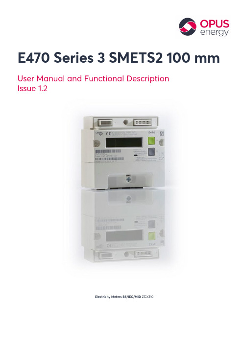
E470 Series 3 SMETS2 100 mm User Manual and Functional DescriptionIssue 1.2Electricity Meters BS/IEC/MID ZCX310Table of Contents1Safety (3)1.1Safety information (3)1.2Meter Operator Code of Practice (3)1.3Safety regulations (3)2Physical description (4)2.1Meter construction (4)3Meter Displays (5)3.1Display and navigation structure (5)3.2Display examples (5)3.2.1Time/date displays (5)3.2.2Total registers (5)3.2.3Rate registers (7)3.2.4Instantaneous values (7)3.2.5MID displays (8)3.2.6Charge displays (8)3.3Credit mode status displays (8)3.3.1Credit mode balance (8)3.3.2Customer PIN enabled but not entered (9)3.3.3Load limit exceeded (9)3.4Debt management displays (9)3.4.1Payment based debt displays (9)3.4.1Time based debt displays (10)Copyright © 2019 Opus Energy Ltd - All rights reserved.The information in this document is the property of Opus Energy Ltd. Please do not copy or communicate the content to a third party, or use it for any other purpose without Opus Energy’s express written consent.1Safety1.1Safety informationThe following symbols are used to draw your attention to the relevant danger level, i.e. the severity and probability of any danger, in the individual sections of this document.DangerThis symbol is used to indicate a possible dangerous situation which could result in severe physical injury or death.WarningThis symbol is used to indicate a possible dangerous situation which could result in minor physical injury or material damage.NoteThis symbol is used to indicate general details and other useful information.In addition to the danger level, safety information also describes the type and source of the danger, its possible consequences, and measures for avoiding the danger.1.2 Meter Operator Code of PracticeThe E470 must be installed in accordance with the Meter Operation Code of Practice Agreement(MOCOPA®), defining safety, technical and business interface requirements regarding the provision of meter operation services.For more information see https:///.1.3 Safety regulationsThe following safety regulations must be observed at all times:•Local safety regulations must be observed and shall take precedence over these regulations in the event of a conflict. Only technically qualified and appropriately trained personnel are authorised to install the meters.•Meters that have been dropped must not be installed, even if no damage is apparent, but must be returned to the service and repair department (or the manufacturer) for testing. Internal damage may result in malfunctions or short-circuits.• The meters must not be cleaned under running water or with compressed air. Water ingress can cause short-circuits.•The meter terminal cover should be secured in place before any load is supplied.2Physical description2.1Meter constructionThis document doesn’t include a description of the internal construction of the meter. Opening the meter after delivery isn’t permitted. If it is opened the meter’s calibration and certification will automatically be rendered void.The meter case is made of antistatic polycarbonate plastic glass filled 10%. The top part of the meter houses an intimate communications hub interface (ICHI).The middle part of the meter – the meter faceplate area – comprises the user interface with the liquid crystal display (LCD) display, the metrology (measurement) light emitting diode (LED) and the display buttons A and B.The lower part of the meter – the terminal area – is protected by a removable terminal cover. It includes the main electricity ingress and egress terminals and auxiliary connections.Figure 1 Front view of meter1 Intimate communications hub interface (ICHI)2 Display button A3 Display button B4 Metrology LED (red)5 Faceplate: see Figure 4 for details6 Terminal cover7 Terminal cover sealing point: wire rope and ferrule8Meter case sealing (left and right side): ultrasonic stakes printed withthe manufacturer’s name (L+G) and the year of manufacture 9 LCD10 ICHI sealing: secured by comms hub screw109 87123 4 5 63Meter Displays3.1Display and navigation structureThe E470 SMETS2 meter has a display structure that provides end users with information relating to the meter’s operation.3.2Display examplesThe following section details the typical displays that the meter supports and includes the following:•Time/date displays•Total register displays•Rate register displays•Instantaneous value displays3.2.1Time/date displaysThe date is shown in the format DD.MM.YY.D a t e01.01.10The time is shown in the format HH:MM:SS T i m e00:00:003.2.2Total registersThe following display formats are for total energy registers. The examples show 5 significant figures and no decimal places – just like it’ll appear on the meter display.Total active import energyimportTotal active export energyexportT O T A Total active energy (sum) (import + export)T O T A Total active energy (net) (import – export)T O T A L(i n d.)Q100000kvarhTotal reactive energy quadrant 1 (import inductive)T O T A L(c a p.)Q200000kvarhTotal reactive energy quadrant 2 (import capacitive)T O T A L(i n d.)Q300000kvarhTotal reactive energy quadrant 3 (export inductive)T O T A L(c a p.)Q400000kvarhTotal reactive energy quadrant 4 (export capacitive)Total reactive import energy (kvarh)Total reactive export energy (kvarh)T O T A L A p p I m p o r t00000kvarhTotal apparent import energy (kVah): +VA (QI+QIV)T O T A L A p p E x p o r t00000kvarh Total apparent export energy (kVah): +VA (QII+QIII)export importexport importimport export3.2.3Rate registersThe meter displays time of use (TOU) rates and block rated registers.TOU Rate xx - active import energy (kWh)(rates 1 to 48)Block xx TOU Rate xx – active import energy (kWh)(Block 01 to 04, TOU Rate 01 to 08)The import and export representation arrow is for Active energy only3.2.4Instantaneous valuesThe meter displays instantaneous values for power, power factor, voltage, current, frequency and meter balance.P o w e r A c t i v e00000.00kWInstantaneous Active Power (kW)P o w e r R e a c t i v e00000.00kvarInstantaneous Reactive Power (kvar)P o w e r A p p a r e n t00000.00kVAInstantaneous Apparent Power (kVA)P o w e r F a c t o r00000.000Power FactorV o l t a g e0000.0VVoltage (V)C u r r e n t0000.00A Current (A)import importMains Frequency (Hz)F r e q u e n c y0000.0HzMeter Balance (Credit Mode)C r e d i t M o d e B a l£0.003.2.5MID displaysThe meter can display the approved and calculated checksums (CRC).Approved CRCA P P R X X X X X X X XM I D C R CCalculated CRCC A L C X X X X X X X XM I D C R C3.2.6Charge displaysThe meter can display the standing charge.Standing charge (pounds and pence)S t a n d i n g C h a r g e£0.003.3Credit mode status displaysThe following section details the displays that the user can see when in the credit mode of operation.3.3.1Credit mode balanceMeter in credit mode: Supply On, Credit meter balance shown.Credit mode balanceimport3.3.2Customer PIN enabled but not enteredDisplay when customer PIN enabled but not entered. Supply status could be any one of the following: off, arm or on.PIN enabled but not entered3.3.3Load limit exceededDisplay when customer has exceeded load limit. Supply status armed.When load limit is exceeded the supply control switchbox symbol flashes3.4Debt management displaysThe meter supports two types of debt collection: payment based and time based (see below).3.4.1Payment based debt displays3.4.1.1Debt remainingWhere the meter is set up to perform payment based debt collection, it will display the amount of debt that the customer has outstanding.D E B T3R E M A I N I N G£15.10Debt remaining3.4.1.1Debt collection percentageThe meter will display that amount of debt to be collected from each top-up performed (detailed as a percentage per payment).D E B T3%P E R P M N T10%Debt remaining percentage per paymentimport import3.4.1.1Maximum debt collection per weekThe meter will detail the maximum amount of debt that it’s able to collect per week from the payment top-ups received.Maximum debt collection per weekD E B T3M A X P E R W K£50.003.4.1.1Debt amount paidThe meter will detail the total amount of debt that’s been paid, based on the payments that the meter has processed.Amount of debt paidD E B T3A M N T P A I D£20.123.4.1 Time based debt displays3.4.1.1Debt remainingWhere the meter is set up to perform time based debt collection, it will display the amount of debt that the customer has outstanding.Amount of debt remainingD E B T1R E M A I N I N G£20.123.4.1.1Debt collection intervalThe meter will display the amount of debt to be collected, detailing the time-period for each collection and the amount of money to be collected at each interval.Debt collection period (One hour or one day)D E B T1/1440min£00.403.4.1.1Debt collection not configuredThe meter will display a ‘not configured’ notification if it hasn’t been set up to collect a time based debt.Debt collection not configuredD E B T1N O T C O N F I G£00.00D000058620 en a – E470 Series 3 SMETS2 100 mm – ZCX310 – User Manual and Functional Description Updated On:28/06/2019Version:1.2 11113.4.1.1Debt amount paidThe meter will detail the total amount of debt paid, based on the payments already processed by the meter.D E B T1A M N T P A I D£15.10Amount of debt paid。
渔翁信息PCI-E加密卡

渔翁信息PCI-E加密卡一、产品介绍渔翁PCI-E密码卡系列产品是渔翁信息技术股份有限公司独立自主研发,在国内率先采用PCI-E总线技术的高速密码设备,遵循国家密码管理局关于PCI-E 密码卡的相关技术规范,通过国家密码管理局鉴定。
产品全面支持SM1、SM2、SM3、SM4、SM9等国密算法以及3DES、AES192、AES256、RSA、SHA1等多种国际标准算法,保证敏感数据的机密性、真实性、完整性和抗抵赖性。
目前已广泛应用于签名验证服务器、IPSec/SSL VPN网关、等安全设备以及电子印章管理、安全公文传输等软件系统,市场前景广阔。
二、功能特点1.密钥生成支持国密SM2算法密钥对的生成、支持RSA密钥对生成、支持对称密钥的生成。
2.密钥存储默认存储64对SM2密钥对和64对RSA密钥对,支持存储1024个对称密钥,可根据客户需求扩展。
3.密钥销毁支持销毁SM2密钥对、RSA 密钥对和通信密钥,且销毁后通过任何技术均无法恢复。
4.密钥更新支持非对称密钥对和对称密钥的更新功能。
5.密钥备份和恢复支持设备内部密钥以密文形式备份至设备外部存储,并采用门限秘密共享机制确保密钥备份安全,备份密钥可恢复到相同型号的其他加密卡设备中。
6.真随机数生成采用经国密局批准使用的物理噪声源产生器生成真随机数,确保密钥安全。
7.非对称加解密支持国密SM2椭圆曲线密码算法加解密,密钥长度为256位;支持RSA算法加解密。
8.对称加解密支持国密SM1、SM4对称算法加解密;支持DES、3DES、AES、AES192、AES256等算法加解密。
9.完整性运算支持国密SM3杂凑算法,支持SHA算法确保数据完整性。
10.签名/签名验证支持非对称算法的私钥对数据进行签名,使用对应的公钥进行签名验证。
11.身份识别支持使用非对称算法的公钥进行用户身份鉴别。
12.开发支持支持微软PKCS#11接口、JCE接口等标准接口;支持用户定制接口的开发;支持《密码设备应用接口规范》国家标准接口;支持多进程、多线程调用。
E470中文说明书_2013

警告图标. 当探测器的坐标旋转了90度,进入控制面板进行修改.
显示单元正在充电. 指示电源适配器接入.
沙漏. 显示单元正在处理任务中.
外接设备. 表示有外部设备接入, 例如,投影仪. Bluetooth®. 蓝牙,表示蓝牙功能已启用. 图标边上的数字表示连接了几个蓝牙单元. 通过热敏打印机打印报告,热敏打印机是选件.
见。
3. 按OK键保存数据.
用条形码保存数据文件
条形码扫描器是单独销售的. 第一次测量某设备后, 贴一张条码标签在设备 上,把标签上相应的条形码序号输入到文件名称中. 下一次检查该设备时,使用 条形码阅读机直接读取条码即可。
1. 扫描机器的的条形码. 2. 输入文件名. 3. 按 OK 保存数据. 所有的数据连同条
带箭头的功能键图标表示包含子菜单
6
用户界面 显显示显单显元显
状态栏
状态栏涵盖了一些附加信息, 如警告信号, 当前时间和蓝牙连接状况等.
测量单位. 可以在参数设置中更改 测量单位.
状态栏上也有一些文字信息: • 选定的图标功能描述. • 提示信息.
状态栏可能出现的图标 警告图标. 按警告图标
对应的功能键,得到详细的警告信息.
Fredrik Eriksson Quality Manager, Damalini AB Damalini AB, PO Box 149, SE-431 22 Mölndal, Sweden Phone: +46 31 708 63 00, E-mail: info@ Web:
介绍
Damalini AB
Damalini AB 研发, 生产,销售 基于激光技术的Easy-Laser®品牌的激光对中 仪和激光几何测量系统
MMSZ4702资料
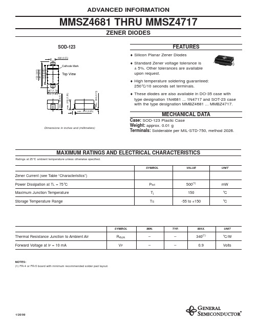
ADVANCED INFORMATION
MMSZ4681 THRU MMSZ4717
ZENER DIODES
SOD-123
.022 (0.55)
FEATURES
♦ Silicon Planar Zener Diodes ♦ Standard Zener voltage tolerance is ± 5%. Other tolerances are available upon request. ♦ High temperature soldering guaranteed: 250°C/10 seconds set terminals.
1.0 1.0 1.0 1.5 2.0 2.0 2.0 3.0 3.0 4.0 5.0 5.1 5.7 6.2 6.6 6.9 7.6 8.4 9.1 9.8 10.6 11.4 12.1 12.9 13.6 14.4 15.2 16.7 18.2 19.0 20.4 21.2 22.8 25.0 27.3 29.6 32.6
1/20/99
元器件交易网
MMSZ4681 THRU MMSZ4717
ELECTRICAL CHARACTERISTICS
TA = 25°C unless otherwise specified Zener Voltage(1) VZ @ IZT = 50µA (Volts) Type Marking Code Nominal Min Max Max Reverse Current IR (µA)
2.00 1.00 0.80 7.50 7.50 5.00 4.00 10.0 10.0 10.0 10.0 10.0 10.0 1.00 1.00 1.00 1.00 0.05 0.05 0.05 0.05 0.05 0.05 0.05 0.05 0.05 0.01 0.01 0.01 0.01 0.01 0.01 0.01 0.01 0.01 0.01 0.01
联想 ThinkPad E470、E470c 和 E475安全、保修和设置指南

ThinkPad® 计算 机
电源线
交流电源适配器
文档
+
:打开“截图工具”程序
:音量控制
TrackPoint 指点设备
初始设置
• 指点 • 左键单击 • •
使用指点杆 移动指针。 按左单击按键 选择或打开某 项。 滚动 按住点状滚动条 同时在水平 或垂直方向上向指点杆施加压力。 右键单击 按右单击按键 显示快捷菜 单。
轨迹板
• 指点 • • •
用一根手指滑过轨迹板表面以移动 指针。 左键单击 按左键单击区域 选择或打开某 项。 滚动 将两根手指放在轨迹板上,沿垂直 或水平方向移动手指。 右键单击 按右键单击区域 显示快捷菜 单。
2. 按电源按键以开启计算机。然后,按照屏幕上的说明完成初始设置。
有关使用轨迹板触摸手势的详细信息,请参阅计算机的《用户指南》。
产品。
合规性信息
可从以下网址获得最新的合规性信息: /compliance
电子辐射声明
本设备经过测试,证实符合 B 类数字设 备限制。本产品的《用户指南》提供适用 于本设备的完整 B 类合规性声明。有关 其他信息,请参阅“访问《用户指南》 ” 。
恢复解决方案
您的计算机可能未附带 Windows 全套恢 复光盘或恢复 U 盘。要恢复 Microsoft® Windows 操作系统,请参阅《用户指 南》中的恢复信息。如需其他信息,请参 阅本文档后面的“访问《用户指南》。
常规电池声明
危险 Lenovo 提供的用于产品的电池已经过兼 容性测试,并应该仅用核准的部件进行更 换。非 Lenovo 指定的电池或经过拆卸 或改装的电池不在保修范围之内。 电池使用不当或错误操作可能导致电池过 热、漏液或爆炸。为避免可能造成的伤 害,请注意以下几点: • 请勿打开、拆开或维修任何电池。 • 请勿挤压或刺穿电池。 • 请勿使电池短路、接触水或其他液体。 • 使电池远离儿童。 • 使电池远离火源。 如果电池损坏,或发现从电池中流出异物 或电池引线上堆积异物,请停止使用电 池。 请在室温下存放可充电电池或含有可充电 电池的产品,并将电池充至大约 30% 到 50% 的电量。建议每年对电池充电一次 以防止过量放电。 请勿将电池丢入以掩埋方式处理的垃圾 中。处理电池时,请遵守当地的法令或法 规。
