HLMP-K105-LK001中文资料
G105-1单螺杆泵
G105-1单螺杆泵
G105-1单螺杆泵技术参数技术参数:单级,由齿轮变速、电磁调速电机加齿轮变速或无级变速电机加齿轮变速时的性能参数.流量:380-252-189m3/h;扬程:80-44-29m;功率:0.75-
37kw;转速:500-960r/min;口径:20-135MM;温度:-15-200℃。
G105-1单螺杆泵是按迥转啮合容积式原理工作的新型泵种,主要工作部件是偏心螺杆(转子)和固定的衬套(定子)。
由于该二部件的特殊几何形状,分别形成单独的密封容腔,介质由轴向均匀推行流动,内部流速低,容积保持不变,压力稳定,因而不会产生涡流和搅动。
每级泵的输出压力为0.6MPa,扬程60m(清水),自吸高度一般在6m,适用于输送介质温度80℃以下(特殊要求可达150℃)。
<br />G105-1单螺杆泵因定子选用多种弹性材料制成,所以这种泵对高粘度流体的输送和含有硬质悬浮颗粒介质或含有纤维介质的输送,有一般泵种所不能胜任的特点。
其流量与转速成正比。
传动可采用联轴器直接传动,或采用调速电机,三角带,变速箱等装置变速。
<br />G105-1单螺杆泵零件少,结构紧凑,体积小,维修简便;转子和定子是G105-1单螺杆泵的易损件,结构简单,便于装拆。
海利普HLP-SK100系列说明书(中文版)
HLP-SK100系列使用说明书
系列
型号
输入电源
输入电 输出电 额定功 适用电 净重/ 流/A 流/A 率/KW 机/KW KG
3×380-440V50/60Hz 175 180
HLP-SK100009043
90 90
3×440-480V50/60Hz 154 160
3×380-440V50/60Hz 206 215
130
7.4 菜单选择
131
7.5 加减速选择
132
第8章 选配件规格
133
8.1 键盘外引安装配件
133
8.1.1 外引键盘通讯电缆
133
8.1.2 键盘外引安装步骤
133
第9章 EMC性能描述
135
9.1 EMC 电磁兼容性
135
9.2 射频干扰开关的使用
135
第10章 故障报警及处理
136
10.1 故障列表
75 75
3×440-480V50/60Hz 113 130
3×380-440V50/60Hz 140 147 75 75
3×440-480V50/60Hz 121 130 HLP-SK100007543
3×380-440V50/60Hz 166 177
90 90 3×440-480V50/60Hz 133 160
HLP-SK100011043
110 110 60
3×440-480V50/60Hz 183 190
3×380-440V50/60Hz 251 260
HLP-SK100013243
132 132
3×440-480V50/60Hz 231 240
3×380-440V50/60Hz 304 315
HLP-C100系列海利普变频器参考资料
HLP-C100系列海利普变频器参考资料1. 产品概述HLP-C100系列海利普变频器是一款高性能的变频器,广泛应用于各种工业自动化控制系统中。
该系列变频器具有稳定可靠、高效能、易操作等特点。
2. 技术参数- 输入电压:220V/380V- 额定功率:1.5kW-315kW- 频率范围:0Hz-400Hz- 输出电流:根据不同型号而定3. 产品特点- 整机结构紧凑,体积小,安装方便。
- 具备过流、过载、过压、欠压等多重保护功能,保证设备的安全运行。
- 支持多种控制方式,如键盘控制、外部信号控制、RS485通信控制等。
- 高效能的PWM控制方式,提供稳定的输出电流和电压。
- 具备良好的动态特性,响应速度快,能够满足各种工况的需求。
- 具有良好的抗干扰能力,适用于复杂的工业环境。
- 支持多种编码器接口,方便与其他设备进行联动控制。
4. 安装和调试- 安装前,请确保电源和电机的接线正确无误。
- 安装过程中,请注意保持变频器的通风良好,避免高温环境。
- 连接控制信号时,请确保信号线的可靠性和正确性。
- 安装完成后,请进行相关参数的设置和调试。
5. 故障排除- 变频器故障常见原因包括过载、过热、电源异常等,请根据具体的故障表现进行排查。
- 在排除故障时,请务必断开电源,并由专业人员进行处理。
- 如有需要,可参考附带的故障代码手册进行故障诊断。
6. 维护保养- 变频器使用一段时间后,应及时清洁设备表面和通风口,避免灰尘堆积影响散热效果。
- 定期检查电源线和控制线的连接状态,确保接触良好。
- 如发现异味、异常噪音等情况,请立即停机检查,并由专业人员进行维修。
以上是HLP-C100系列海利普变频器的参考资料,希望对您有所帮助。
如需进一步了解,请参考产品说明书或联系我们的技术支持团队。
HL-1说明书
HL-1 开发板使用说明书 慧净电子-做人人都买得起的 51 单片机开发板
3.6 利用定时器和蜂鸣器唱歌.......................................................................... 3.7 模数转换 ADC 的应用......................................................................... 3.8 继电器的应用........................................................................ 3.9 DS18B20 温度测量显示实验...................................................................... 3.10 1602 字符液晶显示................................................................................... 3.11 EEPROM AT24C02 实验......................................................................... 3.12 串口通讯实验............................................................................................ 联系方式...................................................................................................................
HLMP-K105-KL001中文资料
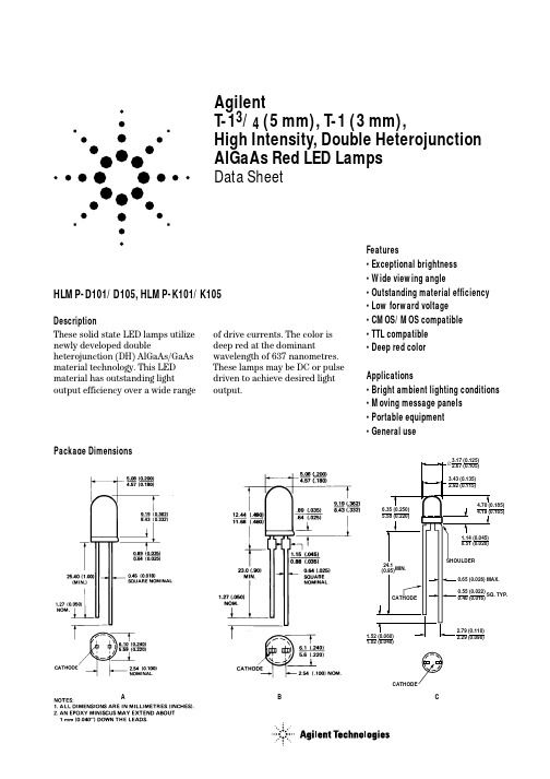
AgilentT-13/4 (5 mm), T-1 (3 mm),High Intensity, Double Heterojunction AlGaAs Red LED LampsData SheetHLMP-D101/D105, HLMP-K101/K105DescriptionThese solid state LED lamps utilize newly developed doubleheterojunction (DH) AlGaAs/GaAs material technology. This LED material has outstanding lightoutput efficiency over a wide rangeFeatures• Exceptional brightness • Wide viewing angle• Outstanding material efficiency • Low forward voltage • CMOS/MOS compatible • TTL compatible • Deep red colorApplications• Bright ambient lighting conditions • Moving message panels • Portable equipment • General useof drive currents. The color is deep red at the dominantwavelength of 637 nanometres.These lamps may be DC or pulse driven to achieve desired light output.Package DimensionsA B CSelection GuideLuminous IntensityIv (mcd) at 20 mA2θ1/2[1]Package Package Description Device HLMP-Min.Typ.Max.Degree Outline T-1 3/4 Red Tinted Diffused D10135.270.0–65AD101-J00xx35.270.0–65AD101-JK0xx35.270.0112.865AT-1 3/4 Red Untinted Non-diffused D105138.0240.0–24BD105-M00xx138.0240.0–24BD105-NO0xx200.0290.0580.024BT-1 Red Tinted Diffused K10122.045.0–60CK101-100xx22.045.0–60CK101-IJ0xx22.045.070.460CT-1 Red Untinted Non-diffused K10535.265.0–45CK105-J00xx35.265.0–45CK105-KL0xx56.4110.0180.445CNote:1. θ1/2 is the off axis angle from lamp centerline where the luminous intensity is 1/2 the on-axis value.Part Numbering SystemHLMP - x x xx - x x x xxMechanical Option00: Bulk01: Tape & Reel, Crimped Leads02: Tape & Reel, Straight LeadsA1: Right Angle Housing, Uneven Leads, T1A2: Right Angle Housing, Even Leads, T1B1: Right Angle Housing, Uneven Leads, T-1 3/4B2: Right Angle Housing, Even Leads, T-1 3/4DD, UQ: Ammo PackColor Bin Options0: Full Color Bin DistributionMaximum Iv Bin Options0: Open (no max. limit)Others: Please refer to the Iv Bin TableMinimum Iv Bin OptionsPlease refer to the Iv Bin TableLens Type01: Tinted, Diffused05: Untinted, NondiffusedColor Options1: AlGaAs RedPackage OptionsD: T-1 3/4K: T-1Absolute Maximum Ratings at T A = 25°CParameter ValuePeak Forward Current[1,2]300 mAAverage Forward Current[2]20 mADC Current[3]30 mAPower Dissipation87 mWReverse Voltage (I R = 100 µA) 5 VTransient Forward Current (10 µs Pulse)[4]500 mALED Junction Temperature110°COperating Temperature Range-20 to +100°C Storage Temperature Range-55 to +100°C Wave Soldering Temperature [1.59 mm (0.063 in.) from body]250°C for 3 seconds Lead Solder Dipping Temperature [1.59 mm (0.063 in.) from body]260°C for 5 seconds Notes:1.Maximum I PEAK at f = 1 kHz, DF = 6.7%.2.Refer to Figure 6 to establish pulsed operating conditions.3.Derate linearly as shown in Figure 5.4.The transient peak current is the maximum non-recurring peak current the device can withstand without damaging the LED die and wire bonds. It isnot recommended that the device be operated at peak currents beyond the Absolute Maximum Peak Forward Current.Electrical/Optical Characteristics at T A = 25°CSymbol Description Min.Typ.Max.Unit Test ConditionV F Forward Voltage 1.8 2.2V I F = 20 mAV R Reverse Breakdown Voltage 5.015.0V I R = 100 µAλp Peak Wavelength645nm Measurement at Peakλd Dominant Wavelength637nm Note 1∆λ1/2Spectral Line Halfwidth20nmτS Speed of Response30ns Exponential TimeConstant, e-t/T SC Capacitance30pF V F = 0, f = 1 MHzRθJ-PIN Thermal Resistance260[3]°C/W Junction to Cathode Lead210[4]290[5]ηV Luminous Efficacy80Im/W Note 2Notes:1.The dominant wavelength, λd, is derived from the CIE chromaticity diagram and represents the color of the device.2.The radiant intensity, I e, in watts per steradian, may be found from the equation I e = l V/ηV, where I V is the luminous intensity in candelas and ηV isluminous efficacy in lumens/watt.3.HLMP-D101.4.HLMP-D105.5.HLMP-K101/-K105.Figure 3. Relative luminous intensity vs. dc forward current.Figure 4. Relative efficiency vs. peak forward current.Figure 7. Relative luminous intensity vs. angular displacement. HLMP-D101.Figure 8. Relative luminous intensity vs. angular displacement. HLMP-K101.Intensity Bin LimitsIntensity Range (mcd)Color Bin Min.Max.Red I24.839.6J39.663.4K63.4101.5L101.5162.4M162.4234.6N234.6340.0O340.0540.0P540.0850.0Q850.01200.0R1200.01700.0S1700.02400.0T2400.03400.0U3400.04900.0V4900.07100.0W7100.010200.0X10200.014800.0Y14800.021400.0Z21400.030900.0Maximum tolerance for each bin limit is ± 18%.Mechanical Option MatrixMechanical Option Code Definition00Bulk Packaging, minimum increment 500 pcs/bag01Tape & Reel, crimped leads, minimum increment 1300 pcs (T-1 3/4)/1800 pcs (T-1) 02Tape & Reel, straight leads, minimum increment 1300 pcs (T-1 3/4)/1800 pcs (T-1) A1Right Angle Housing, uneven leads, minimum increment 500 pcs/bagA2Right Angle Housing, even leads, minimum increment 500 pcs/bagB1Right Angle Housing, uneven leads, minimum increment 500 pcs/bagB2Right Angle Housing, even leads, minimum increment 500 pcs/bagDD Ammo Pack, straight leads in 2K incrementUQ Ammo Pack, horizontal leads in 2K incrementNote:All categories are established for classification of products. Products may not be available in all categories. Please contact your local Agilent representative for further clarification/information./semiconductors For product information and a complete list of distributors, please go to our web site.For technical assistance call:Americas/Canada: +1 (800) 235-0312 or (916) 788-6763Europe: +49 (0) 6441 92460China: 10800 650 0017Hong Kong: (+65) 6756 2394India, Australia, New Zealand: (+65) 6755 1939 Japan: (+81 3) 3335-8152 (Domestic/Interna-tional), or 0120-61-1280 (Domestic Only) Korea: (+65) 6755 1989Singapore, Malaysia, Vietnam, Thailand, Philippines, Indonesia: (+65) 6755 2044 Taiwan: (+65) 6755 1843Data subject to change.Copyright © 2004 Agilent Technologies, Inc. Obsoletes 5968-1440ENovember 12, 20045988-2230EN。
lk培训手册

LK PLC 培训手册
2. 高可靠性
提供冗余系统的解决方案,支持电源冗余、CPU 冗余、以太网冗余、总线冗余 具备良好的电磁兼容性,现场到系统、通道与通道间采用隔离措施 具有通信故障时的输出保持或输出预置功能 低功耗无风扇设计,模块运行中无过热现象
3. 易用性和易维护性
模块支持带电插拔,更换时无需中断系统运行,新模块将自动进行数据的初始化设置, 并快速与 CPU 建立通信
二、LK-PLC 特点
1. 高性能
配置工业级 100MHz/266MHz/533MHz 处理器,拥有纳秒级(13ns)的处理速度 系统 I/O 容量大,数字量 I/O 最多可达 57344 点,模拟量 I/O 最多可达 3584 点 具有大容量内存。用于程序,最大 16MB;用于数据,最大 64MB+1MB 掉电保持区 强大的模拟量处理功能
模块智能化程度高,可实现强大的自诊断功能 编程软件符合 IEC61131-3 国际标准,具有 IL、LD、FBD、SFC、ST 五种编程语言 灵活的 SD 存储卡,使系统维护更加方便、快捷 背板上设计有防混销,以避免插错模块 外形小巧,易于安装。既可分散,也可集中
4. 开放性和灵活性
支持多种通信协议,如 TCP/IP、PROFIBUS-DP、MODBUS、DeviceNet、自由口等协 议
采用开放式设计,可为各类 HMI 软件提供标准接口 强大的扩展能力 提供普通和高速两种不同类型、不同成本的 I/O 模块
5. 设计新颖
微型化设计,结构紧凑,大大节省了系统的安装空间 独特的接线端子设计,接线端子固定在背板上,独立于 I/O 模块
LK 冗余系统包括支持冗余功能的 CPU 模块、PROFIBUS-DP 通信接口模块、本地背板 (双 CPU 插槽)、扩展背板和普通的 I/O 模块组成,两个 CPU 之间的数据同步通过高速背 板总线,无需专门的同步模块。
科隆流量计选型手册

OPTIFLUX 系列及其它技术数据表电磁流量计OPTIFLUX 1300 / 2300 / 4300 / 5300 / 6300 电磁流量计,拥有强大的自诊断功能,有各种安装接口,有各种衬里和电极材料,最高精度可达0.15%,重复性0.06% OPTIFLUX 2100 / 4100 电磁流量计(IFM 4080 升级换代产品,有自诊断功能)K300 一体型电磁流量计/ K 450K + F 电磁流量计高压电磁流量计科隆电磁流量计经济型K 300(一体型)模拟量K 450(一体或分体型)模拟量(带显示)特殊型OPTIFLUX 4040 C 两线制TIDALFLUX 4110 PF 非满管BATCHFLUX 5015 C 灌装式卫生型常用型W FOPTIFLUX 6300 C1. 性能简介1- 52. 常用产品2.1 OPTIFLUX 2300 / 4300 电磁流量计62.1 .1I FC 300 信号转换器6- 162.2 OPTIFLUX 2100 / 4100 电磁流量计172.2 .1I FC 100 信号转换器17- 2021- 22232425263. 经济型30- 313 .2K450K + F 电磁流量计32- 334. 选型与安装4.1传感器口径选择34- 354 .2电极形式 / 材料选择364.3衬里材料的选择374.4传感器在管线上的安装38- 416. 原理及标定证书44目录2.3 OPTIFLUX 2000/4000传感器2.4 IFS / 4000-HP 高压传感器2.5 IFM 3100K +F 电磁流量计2.6 OPTIFLUX 1300夹持型电磁流量计2.7 OPTIFLUX 5300 S W 陶瓷型夹持式电磁流量计2.7.1 OPTIFLUX 5300 FL 法兰型272.8 OPTIFLUX 6300 卫生接口型电磁流量计28- 293.1 K 300 一体型电磁流量计5. 产品选型编码42- 431. 性能简介OPTIFLUX 2300 / 4300 W(可选 C + F + R)DN 10 ~ 3000OPTIFLUX (一体)(墙挂分体)2100 / 4100 C + W DN 10 ~ 1200详细数据见P 6详细数据见P 17OPTI FLUX 2000(橡胶)/ OPTI FLUX 4000(四氟、PFA )+ / -0.3%±1mm / s (取决于传感器)OPTI FLUX 2000(橡胶)/ OPTI FLUX 4000(四氟、PFA )0.2% - 0.3%(液体中最多含30% 的固体成份)IFM 3100 / 3300 C + W1. 性能简介仪表性能同OPTIFLUX4100,传感器见M 900,见P 24K 300DN 10 ~ 300K 300≤1%详细数据见P 30DN 50 ~ 300M 900+ / -0.3% ±1mm / s(取决于传感器)K 4501. 性能简介DN 10 ~ 450 IFS4000≤0.5%DN 10 ~ 150 OPTIFLUX 1300 OPTIFLUX 10000.3%1. 性能简介OPTIFLUX 5300OPTIFLUX 63001. 性能简介OPTIFLUX 4040TIDALFLUX 4110 PFIFC 300 信号转换器1 图形显示器,背光(白)2 第1 行和第2 行用于显示不同的测量变量,大字体格式显示时只显示一个变量3 第三行显示条形图4 光感应键,无需打开盖就可操作信号转换器5 蓝色条显示:·测量模式时显示仪表位号·设置模式时显示菜单/ 功能名称6 X 指示有键按动7 指示红外线输出工作,此时4 光感应键失效8 连接KROHNE GDC 总线的插座9 光电感应接口,用于无线传送数据(输入/ 输出)IFC 300 显示 / 操作和调整键IFC 300 C 和IFC 300 F 的o 显示器可以隔90旋转2.1 IFC 300 信号转换器2.1 IFC 300 信号转换器使用特点·工厂设置(有二个记忆芯片,一个在机内,另一个在机芯外的底板上)·可以存储3组设定数据,factrory settings 为工厂设定数据用户不能更改(传感器的GK 值、满量程、零点、线圈阻值、温度等)机外底板上的记忆芯片机内记忆芯片·更换转换器时无需设置数据,直接从机芯外的底板上取出工厂设定数据。
LK PLC产品知识介绍

数字量输出模块
8 型号:LK710/LK720 8 16或8通道, 8 输出信号类型:24VDC晶体管输出,0.5A / 继电器输出,2A;
数字量I/O模块
模拟量I/O模块
模拟量输入模块
8 型号:LK410/LK411/LK430/LK441 8 8或6通道 8 分辨率:16位 8 信号输入:电压、电流、RTD、TC、mV信号
操作站 操作站
系统组成
8 两套热备CPU
冗余环形以太网
8 两个同步模块(光纤)
从机
主机
8 通讯接口模块 8 I/O模块
同步光纤 冗余PROFIBUS-DP
系统功能
8 电源冗余 8 CPU冗余 8 以太网冗余 8 总线冗余 8 双背板冗余
远程 I /O
远程 I /O
冗余系统——特点
集成的冗余功能
透明的编程 PLC硬件配置和程序的编写与单机系统相同 工程下载到主机后,系统自动备份给从机
背板
本地背板:为主背板,用于安装CPU模块、高 速或普通I/O模块、通信接口模块、特殊功能 模块。本地背板包括单CPU插槽背板和冗余 CPU插槽背板。 扩展背板:用于安装通信接口模块、普通I/O 模块、特殊功能模块。
CPU模块
CPU模块是系统的核心,用于执行程 序,处理本地I/O模块和过程数据,通过现 场总线控制分布式I/O。
LK冗余——单机架冗余
操作站 操作站
系统组成
8 1个冗余CPU插槽的本地背板
冗余环形以太网
8 两个支持冗余系统的CPU模块 8 通讯接口模块 8 I/O模块
冗余主站
系统功能
冗余PROFIBUS-DP
8 电源冗余 8 CPU冗余 8 以太网冗余 8 总线冗余
科泰公司产品说明基本配置介绍
公司产品及基本配置介绍 公司产品及基本配置介绍 产品
上海科泰电源股份有限公司 —销售服务中心
版本编号:VO.0904-03
Logo
公司产品及基本配置介绍
1、K系列机组型号说明; 2、K系列柴油发电机组及基本配置; 3、K系列小功率柴油发电机组及基本配置; 4、特殊用途柴油发电机组; 5、8000系列控制屏及配套件; 6、自动负载切换屏(ATS); 7、机组随机配置
SHANGHAI COOLTECH POWER A NTA855-G1 NTA855-G1A NTA855-G2A NTA855-G4 NTAA855-G7 KTA19-G3 KTA19-G4 KTAA19-G5 KTAA19-G6 KTAA19-G7 KTA38-G2 KTA38-G2A KTA38-G5
上海科泰电源股份有限公司
SHANGHAI COOLTECH POWER CO., LTD
Logo
基本说明
4、ATS SMVS、SMVE(将淘汰,ATYS代替),海外室外使用的KK系列可选 项 5、开关 ABB标准配置,S系列3极(最大1600A)、F系列3极固定式(最大 4000A) 增加了F系列4极固定式、F系列抽屉式、E系列及施耐德MT、MW系 列开关选项 6、车载 增加了工程抢险车车辆目录 7、其他 圆形油箱可选项
上海科泰电源股份有限公司
SHANGHAI COOLTECH POWER CO., LTD
Logo
KJ系列机组 KJ系列机组
KJ系列31-450KVA
上海科泰电源股份有限公司
SHANGHAI COOLTECH POWER CO., LTD
Logo
KJ系列机组 KJ系列机组
JOHN DEERE发动机型号含义 1 2 3 4 5 6 CD 4 039 D 123456 4 039 D F 1、生产地代码 CD- 法国萨兰SARAN TO-DUBUQUE,LOWA美国爱德华州迪比克 RG-WATERLOO,LOWA美国爱德华州沃特卢 2、气缸数 3 、4 或 6 3、排气量 (升) 4、进气方式 D – 自然进气 T—涡轮增压, A—涡轮增压加中冷, 水对空 H—涡轮增压加中冷, 空对空 5、柴油机系列号 123456 6、用户代码 F(OEM) 7、设计序号 123(三位数,未用)
HLMP-BL01-S0TYY中文资料
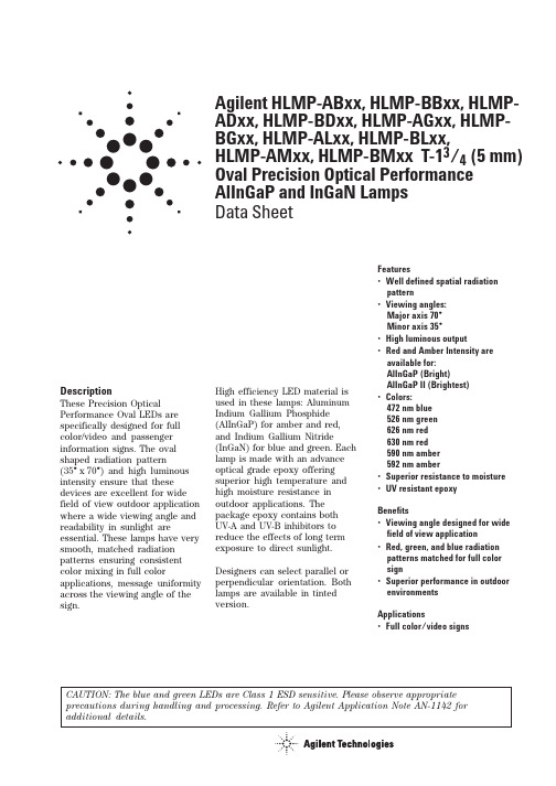
Agilent HLMP-ABxx, HLMP-BBxx, HLMP-ADxx, HLMP-BDxx, HLMP-AGxx, HLMP-BGxx, HLMP-ALxx, HLMP-BLxx,HLMP-AMxx, HLMP-BMxx T-13/4 (5 mm)Oval Precision Optical Performance AlInGaP and InGaN Lamps Data SheetFeatures•Well defined spatial radiation pattern•Viewing angles:Major axis 70°Minor axis 35°•High luminous output•Red and Amber Intensity are available for:AlInGaP (Bright)AlInGaP II (Brightest)•Colors:472 nm blue 526 nm green 626 nm red 630 nm red 590 nm amber 592 nm amber•Superior resistance to moisture •UV resistant epoxyBenefits•Viewing angle designed for wide field of view application•Red, green, and blue radiation patterns matched for full color sign•Superior performance in outdoor environments Applications•Full color/video signsDescriptionThese Precision O ptical Performance Oval LEDs are specifically designed for full color/video and passenger information signs. The oval shaped radiation pattern(35°x 70°) and high luminous intensity ensure that these devices are excellent for wide field of view outdoor application where a wide viewing angle and readability in sunlight areessential. These lamps have very smooth, matched radiation patterns ensuring consistent color mixing in full colorapplications, message uniformity across the viewing angle of the sign.High efficiency LED material is used in these lamps: Aluminum Indium Gallium Phosphide (AlInGaP) for amber and red,and Indium Gallium Nitride(InGaN) for blue and green. Each lamp is made with an advance optical grade epoxy offering superior high temperature and high moisture resistance in outdoor applications. The package epoxy contains both UV-A and UV-B inhibitors to reduce the effects of long term exposure to direct sunlight.Designers can select parallel or perpendicular orientation. Both lamps are available in tinted version.CAUTION: The blue and green LEDs are Class 1 ESD sensitive. Please observe appropriate precautions during handling and processing. Refer to Agilent Application Note AN-1142 for additio nal details.Table 1. Device Selection Guide for AlInGaP IIColor and Luminous Luminous ForwardDominant Intensity,Intensity,Voltage,LeadsWavelength I v (mcd) at I v (mcd) at V f (V)with Leadframe Package Part Numberλd (nm) Typ.20 mA Min.20 mA Max.Max.Stand-offs Orientation Drawing HLMP-AD06-P00xx Red 630880 2.4No Parallel A HLMP-AD06-P0Txx Red 630880 2.6No Parallel A HLMP-AD16-P00xx Red 630880 2.4Yes Parallel B HLMP-AD16-P0Txx Red 630880 2.6Yes Parallel B HLMP-AD16-RS0xx Red 63015002500 2.6Yes Parallel B HLMP-AD16-RSTxx Red 63015002500 2.6Yes Parallel B HLMP-AD16-RU0xx Red 63015004200 2.4Yes Parallel B HLMP-AD16-RUTxx Red 63015004200 2.6Yes Parallel B HLMP-AD16-ST0xx Red 63019003200 2.4Yes Parallel B HLMP-AD16-STTxx Red 63019003200 2.6Yes Parallel B HLMP-AL06-L00xx Amber 592400 2.4No Parallel A HLMP-AL06-L0Rxx Amber 592400 2.6No Parallel A HLMP-AL06-N00xx Amber 592680 2.4No Parallel A HLMP-AL06-N0Rxx Amber 592680 2.6No Parallel A HLMP-AL16-N00xx Amber 592680 2.4Yes Parallel B HLMP-AL16-N0Rxx Amber 592680 2.6Yes Parallel B HLMP-AL16-PSRxx Amber 5928802500 2.6Yes Parallel B HLMP-AL16-QR0xx Amber 59211501900 2.4Yes Parallel B HLMP-AL16-QRRxx Amber 59211501900 2.6Yes Parallel B HLMP-BD06-P00xx Red 630880 2.4No Perpendicular C HLMP-BD06-P0Txx Red 630880 2.6No Perpendicular C HLMP-BD06-RS0xx Red 63015002500 2.4No Perpendicular C HLMP-BD06-RSTxx Red 63015002500 2.6No Perpendicular C HLMP-BD16-P00xx Red 630880 2.4Yes Perpendicular D HLMP-BD16-P0Txx Red 630880 2.6Yes Perpendicular D HLMP-BD16-RU0xx Red 63015004200 2.4Yes Perpendicular D HLMP-BD16-RUTxx Red 63015004200 2.6Yes Perpendicular D HLMP-BD16-ST0xx Red 63019003200 2.4Yes Perpendicular D HLMP-BD16-STTxx Red 63019003200 2.6Yes Perpendicular D HLMP-BL06-N00xx Amber 592680 2.4No Perpendicular C HLMP-BL06-N0Rxx Amber 592680 2.6No Perpendicular C HLMP-BL06-QRKxx Amber 59211501900 2.4No Perpendicular C HLMP-BL06-QRSxx Amber 59211501900 2.6No Perpendicular C HLMP-BL16-N00xx Amber 592680 2.4Yes Perpendicular D HLMP-BL16-N0Rxx Amber 592680 2.6Yes Perpendicular D HLMP-BL16-PS0xx Amber 5928802500 2.4Yes Perpendicular D HLMP-BL16-PSRxx Amber 5928802500 2.6Yes Perpendicular DTable 2. LED IndicatorsDevice Selection Guide for AlInGaPColor and Luminous LuminousDominant Intensity,Intensity,LeadsWavelength I v (mcd) at I v (mcd) at with Leadframe Package Part Numberλd (nm) Typ.20 mA Min.20 mA Max.Stand-offs Orientation Drawing HLMP-AG01-K00xx Red 626310No Parallel A HLMP-AG11-KN0xx Red 626310880Yes Parallel B HLMP-AL01-K00xx Amber 590310No Parallel A HLMP-AL01-LP0xx Amber 5904001150No Parallel A HLMP-AL01-NR0xx Amber 5906801900No Parallel A HLMP-AL11-KN0xx Amber 590310880Yes Parallel B HLMP-AL11-NR0xx Amber 5906801900Yes Parallel B HLMP-BG01-LM0xx Red 626400520No Perpendicular C HLMP-BG01-MN0xx Red 626520880No Perpendicular C HLMP-BG11-KN0xx Red 626310880Yes Perpendicular D HLMP-BL01-NR0xx Amber 5906801900No Perpendicular C HLMP-BL11-KN0xx Amber 590310880Yes Perpendicular D HLMP-BL11-NR0xx Amber 5906801900Yes Perpendicular DTable 3. Device Selection Guide for InGaNColor and Dominant Luminous Intensity,Leads with Leadframe Package Part Number Wavelength λd (nm) Typ. Iv (mcd) at 20 mA Min.Stand-offs Orientation Drawing HLMP-AB01-J00xx Blue 472240No Parallel A HLMP-BB11-J00xx Blue 472240Yes Perpendicular D HLMP-BB11-K00xx Blue 472310Yes Perpendicular D HLMP-BM11-L00xx Green 526400Yes Perpendicular D HLMP-BM11-Q00xx Green 5261150Yes Perpendicular D HLMP-AB11-J00xx Blue 472240Yes Parallel B HLMP-AM01-Q00xx Green 5261150No Parallel A HLMP-BB01-J0Bxx Blue 472240No Perpendicular C HLMP-BB11-KN0xx Blue 472310Yes Perpendicular D HLMP-BM01-L00xx Green 526400No Perpendicular C Tolerance for intensity range limit is ±15%.Part Numbering SystemHLMP-X X X X - X X X XXMechanical Options00: Bulk PackagingDD: Ammo PackYY: Flexi-Bin; Bulk PackagingZZ: Flexi-Bin; Ammo PackColor Bin0: No Color Bin LimitationR: Color Bins 1, 2, 4, and 6 with V F max of 2.6 VT: Red Color with V F max of 2.6 VB: Color bin 2 and 3 onlyK: Color bins 2 and 4 onlyS: Color bins 2 and 4 with VF max of 2.6 VMaximum Intensity Bin0: No Iv Bin LimitationMinimum Intensity BinTint Option1 or 6: Matching Color TintsStandoff Option0: Without1: WithColorB: 472 nm BlueD: 630 nm RedG: 626 nm RedL: 590 or 592 nm AmberM: 526 nm GreenPackageA: 5 mm 35° x 70° Oval, ParallelB: 5 mm 35° x 70° O val, PerpendicularPackage Dimensions5.00 ±(0.197 ±8.71 ± 0.200.50 ± 0.10SQ. TYP.5.00 ±(0.197 ±5.00 ±(0.197 ±5.00 ±(0.197 ±ABCDNOTES:1. ALL DIMENSIONS ARE IN MILLIMETERS (INCHES).2. LEADS ARE MILD STEEL, SOLDER DIPPED.3. TAPERS SHOWN AT TOP OF LEADS (BOTTOM OF LAMP PACKAGE) INDICATE AN EPOXY MENISCUS THAT MAY EXTEND ABOUT 1 mm (0.040 IN.) DOWN THE LEADS.4. RECOMMENDED PC BOARD HOLE DIAMETERS:– LAMP PACKAGES A AND C WITHOUT STAND-OFFS: FLUSH MOUNTING AT BASE OF LAMP PACKAGE = 1.143/1.067 mm (0.044/0.042 IN.).– LAMP PACKAGES B AND D WITH STAND-OFFS: MOUNTING AT LEAD STAND-OFFS.Absolute Maximum Ratings at T A = 25˚CParameter Blue and Green Red and Amber DC Forward Current[1]30 mA50 mAPeak Pulsed Forward Current[2]100 mA100 mAAverage Forward Current30 mA30 mAReverse Voltage (I R = 100 µA) 5 VReverse Voltage (I R = 10 µA) 5 VPower Dissipation120 mW120 mWLED Junction Temperature130°C130°COperating Temperature Range–40°C to +80°C–40°C to +100°C Storage Temperature Range–40°C to +100°C–40°C to +120°C Wave Soldering Temperature[3]250°C for 3 seconds250°C for 3 seconds Notes:1.Derate linearly from Figure 7.2.Duty Factor 30% KHz.3.1.59 mm (0.060 in.) below body.Electrical/Optical Characteristics at T A = 25°CParameter Symbol Min.Typ.Max.Units Test Conditions Typical Viewing AngleMajor2θ1/270degMinor35Forward Voltage V F V I F = 20 mARed (λd = 626 nm) 2.0 2.4Red (λd = 630 nm)Option xx0xx 2.2 2.4Option xxTxx 2.3 2.6Amber (λd = 590 nm) 2.0 2.4Amber (λd = 592 nm)Option xx0xx 2.2 2.4Option xxRxx, xxSxx 2.3 2.6Blue (λd = 472 nm) 3.5 4.0Green (λd = 526 nm) 3.5 4.0Reverse VoltageAmber, Red V R520V I R = 100 µABlue, Green5–I R = 10 µAPeak Wavelength Peak of Wavelength of Amber (λd = 592 nm)λpeak594nm Spectral Distribution Red (λd = 630 nm)639at I F = 20 mABlue (λd = 472 nm)470Green (λd = 526 nm)524Spectral Halfwidth Wavelength Width Amber (λd = 592 nm)∆λ1/217nm at Spectral Distribution Red (λd = 630 nm)171/2 Power Point at Blue (λd = 472 nm)35I F = 20 mAGreen (λd = 526 nm)47Capacitance V F = 0, F = 1 MHz Amber, Red C40pFBlue, Green43Luminous Efficacy Emitted Luminous Amber (λd = 592 nm)ηv500lm/W Power/Emitted Radiant Red (λd = 630 nm)155Power at I F = 20 mA Blue (λd = 472 nm)75Green (λd = 526 nm)520Thermal Resistance RΘJ-PIN240°C/W LED Junction-to-Cathode LeadNotes:1.2θ1/2 is the off-axis angle where the luminous intensity is 1/2 the on-axis intensity.2.The radiant intensity, I e in watts per steradian, may be found from the equation I e = I v/ηv where I v is the luminous intensity in candelas and ηv isthe luminous efficacy in lumens/watt.3.The luminous intensity is measured on the mechanical axis of the lamp package.4.The optical axis is closely aligned with the package mechanical axis.5.The dominant wavelength, λd, is derived from theCIE Chromaticity Diagram and represents the color of the lamp.6.For Options -xxRxx, -xxSxx and -xxTxx, max. forward voltage (Vf) is 2.6 V. Refer to Vf bin table.Figure 1. Relative intensity vs. wavelength.Figure 2. Blue, green forward current vs.forward voltage.WAVELENGTH – nmR E L A T I V E I N T E N S I T Y1.00.500.40.30.20.10.60.70.80.9030251510I F – F O R W A R D C U R R E N T – m AV F – FORWARD VOLTAGE – V2.42.83.2 3.6520 2.6 3.0 3.4Figure 3a. Amber, red forward current vs.forward voltage.Figure 4. Blue, green relative luminous intensity vs. forward current.1.50.5I N T E N S I T Y N O R M A L I Z E D A T 20 m AI F – FORWARD CURRENT – mA01020301.051525C U R R E N T – m AV F – FORWARD VOLTAGE – V Figure 3b. Forward current vs. forward voltage for option -xxTxx red, and option -xxRxx and -xxSxx amber.D C F O R W A R D C U R RE N T – m AFORWARD VOLTAGE – VFigure 6. Blue, green maximum forward current vs. ambient temperature.Figure 7. Amber, red maximum forward current vs. ambient temperature.I F – F O R W A R D C U R R E N T – m A0T A – AMBIENT TEMPERATURE – °C40804020102060301005152535I F – F O R W A R D CU R R E N T – m AT A – AMBIENT TEMPERATURE – °CFigure 5. Amber, red relative luminous intensity vs. forward current.R E L A T I V E I N T E N S I T Y (N OR M A L I Z E D A T 20 m A )FORWARD CURRENT – mAFigure 8. Spatial radiation pattern – 35 x 70 degree lamps.R E L A T I V E I N T E N S I T Y – %1000VERTICAL ANGULAR DISPLACEMENT – DEGREES8060507020501030404020-10-30-50903010-20-40R E L A T I V E I N T E N S I T Y – %1000HORIZONTAL ANGULAR DISPLACEMENT – DEGREES8060507020501030404020-10-30-50903010-20-40Intensity Bin Limits (mcd at 20 mA)Bin Name Min.Max.G 140180H 180240J 240310K 310400L 400520M 520680N 680880P 8801150Q 11501500R 15001900S 19002500T 25003200U19002500Tolerance for each bin limit is ±15%.Amber Color Bin Limits (nm at 20 mA)Bin Name Min.Max.1584.5587.02587.0589.54589.5592.06592.0594.5Tolerance for each bin limit is ± 0.5 nm.Notes:1.All bin categories are established for classifi-cation of products. Products may not beavailable in all bin categories. Please contact your Agilent representative for further information.2. Vf bin table only available for those numbers with options -xxRxx, -xxSxx, -xxTxx.Blue Color Bin Limits (nm at 20 mA)Bin Name Min.Max.1460.0464.02464.0468.03468.0472.04472.0476.05476.0480.0Tolerance for each bin limit is ± 0.5 nm.Green Color Bin Limits (nm at 20 mA)Bin Name Min.Max.1520.0524.02524.0528.03528.0532.04532.0536.05536.0540.0Tolerance for each bin limit is ±0.5 nm.Vf Bin Table [2]Bin Id Min.Max.VA 2.0 2.2VB 2.2 2.4VC2.4 2.6/semiconductors For product information and a complete list of distributors, please go to our web site.For technical assistance call:Americas/Canada: +1 (800) 235-0312 or (916) 788-6763Europe: +49 (0) 6441 92460China: 10800 650 0017Hong Kong: (+65) 6756 2394India, Australia, New Zealand: (+65) 6755 1939 Japan: (+81 3) 3335-8152(Domestic/Interna-tional), or 0120-61-1280(Domestic Only) Korea: (+65) 6755 1989Singapore, Malaysia, Vietnam, Thailand, Philippines, Indonesia: (+65) 6755 2044 Taiwan: (+65) 6755 1843Data subject to change.Copyright © 2004 Agilent Technologies, Inc. August 27, 20045988-9224EN。
LK电阻焊机控制器使用说明书

L K 电阻焊机控制器使用说明书天津七所高科技有限公司二零零四年七月1 简介LK控制器以PHILIPS 80C592为核心芯片,对焊接电流进行同步恒流控制,可以广泛应用于各种单相悬挂式、固定式及一体化式电阻点焊机。
LK控制器具有单、连点焊接功能及CAN数据总线接口,可用在流水线上进行自动焊接;焊接加热脉冲可设定为单脉冲及多个脉冲,配合16种焊接规范,以满足对不同材料、厚度的高质量焊接要求;CAN数据总线接口,应用于焊机联网系统,实现焊装生产线上焊机的集中控制和数据采集、参数修改、故障报警的生产管理;此外,LK控制器还具有焊接电流自动补偿、电极磨损和寿终监视功能以及傻瓜式的中文大屏幕液晶显示,可方便地了解焊接过程中各种参数、故障情况。
本控制器由控制器主体及编程监视器组成,各部分名称请参见“控制箱主体及编程监视器图”。
2 特点2.1 焊接过程由微机进行闭环控制,在电网电压波动及焊接负载变化的情况下,均能保证焊接电流的恒定。
2.2 控制方式有恒流方式、恒压方式及恒相位方式。
2.3 焊接循环中,如预压、加压、预热、焊接、回火、冷却、保持、休止等各工序中的时间长度由程序设定,无误差。
2.4 可带二把焊钳,每把焊钳7个焊接规范,1个修磨规范;或一把焊钳,10/16个规范。
2.5 单点和连点焊接功能,且有多脉冲选择,焊接脉冲数最多可达9个。
2.6 电极磨损焊接电流自动补偿功能,可依据焊点数的增加自动增加焊接电流,平台阶数可达10个;同时,还可根据焊点数及时告之电极需修磨或更新。
2.7 具有焊接压力控制功能,对配有比例阀接口的控制器,可在不同规范中设定不同的焊接压力,不仅可实现锻压功能还可实现焊接过程的压力变化控制。
2.8 功率因数自适应,适合不同的主机。
2.9 傻瓜式编程及较强的显示和自检功能,采用大屏幕汉字液晶显示器,编程菜单化,可显示焊接电流、周波数、控制角及导通角等参数值;同时自动检测诸如可控硅直通、变压器(可控硅)过热等故障。
KT105中文资料
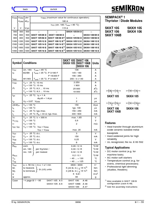
© by SEMIKRON 0898B 1 – 55V RSM V RRM (dv/I TRMS (maximum value for continuous operation)V DRM dt)cr 180 AI TAV (sin. 180; T case = 80 °C)VVV/µs115A500700900130015001700190040060080012001400160018005005005001000100010001000–SKKT 105/06 D SKKT 105/08 D SKKT 105/12 E SKKT 105/14 ESKKT 105/16 E SKKT 105/18 E–SKKT 106/06 DSKKT 106/08 D 1)SKKT 106/12 E1)SKKT 106/14 E 1)SKKT 106/16 E1)SKKT 106/18 E 1)SKKH 105/04 D–SKKH 105/08 DSKKH 105/12 ESKKH 105/14 E SKKH 105/16 E SKKH 105/18 E–SKKH 106/06 DSKKH 106/08 DSKKH 106/12 E SKKH 106/14 E SKKH 106/16 E SKKH 106/18 ESymbol ConditionsSKKT 105SKKH 105SKKT 106SKKT 106B SKKH 106UnitsITAV I D I RMS sin. 180;T case = 85 °C B2/B6T amb = 35 °C;P 3/180 FP 16/200 FW1/W3T amb = 35 °C;P 3/180 F 106145 / 180190 / 260200 / 3 x 140A A A A I TSMi 2t T vj = 25 °C; 10 ms T vj = 130 °C; 10 msT vj = 25 °C; 8,3 ... 10 ms T vj = 130 °C; 8,3 ... 10 ms 2 2501 90025 00018 000A A A 2s A 2s t gd t gr T vj = 25 °C;I G = 1 Adi G /dt = 1 A/µs V D = 0,67 . V DRM12µs µs (di/dt)cr t q I H I L T vj = 130 °CT vj = 130 °CT vj = 25 °C; typ./max.T vj = 25 °C; R G = 33 Ω; typ./max.150typ. 100150 / 250300 / 600A/µs µs mA mA V TV T(TO)r TI DD ; I RD T vj = 25 °C; I T = 300 A T vj = 130 °CT vj = 130 °CT vj = 130 °C;V RD = V RRMV DD = V DRM max. 1,650,92max. 20V V m ΩmA V GT I GT V GD I GD T vj = 25 °C; d.c.T vj = 25 °C; d.c.T vj = 130 °C; d.c.T vj = 130 °C; d.c.31500,256V mA V mA R thjcR thch T vj T stg cont.sin. 180per thyristor / rec. 120per module0,28 / 0,140,30 / 0,150,32 / 0,160,2 / 0,1– 40 ... + 130– 40 ... + 125°C/W °C/W °C/W °C/W °C °C V isol M 1M 2a w a. c. 50 Hz; r.m.s; 1 s/1 min to heatsink to terminals approx.3600 / 30005 (44 lb. in.) + 15 %2)3 (26 lb. in.) + 15 %2)5 . 9,8195V~Nm Nm m/s 2gCase→ page B 1 – 95SKKT 105:A 5SKKT 106: A 46SKKH 105:A 6SKKT 106B: A 48SKKH 106: A 47SEMIPACK ® 1Thyristor / Diode Modules SKKT 105SKKH 105SKKT 106SKKH 106SKKT 106BFeatures•Heat transfer through aluminium oxide ceramic isolated metal baseplate•Hard soldered joints for high reliability•UL recognized, file no. E 63 532Typical Applications•DC motor control (e.g. for machine tools)•AC motor soft starters•Temperature control (e.g. for ovens, chemical processes)•Professional light dimming (studios, theaters)1)Also available in SKKT 106 B configuration (case A 48)2)See the assembly instructionsSKKT 106SKKT 106BSKKH 105SKKH 106© by SEMIKRON© by SEMIKRON B 1 – 57© by SEMIKRON© by SEMIKRON SKKT 19 . . . 105Case A 5SEMIPACK ® 1IEC 192-2: A 77 A JEDEC: TO-240 AAUL recognized, file no. E 63 532SKKT 20/ . . . 106/Case A 46SEMIPACK ® 1IEC 192-2: A 77 A JEDEC: TO-240 AADimensions in mmDimensions in mmSKKD 26 . . . 100Case A 10SKNH 56 . . . 91Case A 7SKKH 26 . . . 105Case A 6SKKL 56 . . . 105Case A 9SKND 46 . . . 81Case A 19SKMT 92Case A 72SKKE 81Case A 12SKKH 27 . . . 106Case A 47SKKT 20 B . . . 106 B Case A 48SKKL 42 . . . 106Case A 59。
HLMP-2735中文资料

LED Light Bars Technical DataFeatures•Large Bright, Uniform Light Emitting Areas•Choice of Colors •Categorized for Light Output •Yellow and Green Categorized for Dominant Wavelength•Excellent ON-OFF Contrast •X-Y Stackable•Flush Mountable•Can be Used with Panel and Legend Mounts• Light Emitting Surface Suitable for Legend Attachment per Application Note 1012•HLCP-X100 Series Designed for Low Current Operation •Bicolor Devices Available Applications•Business MachineMessage Annunciators •Telecommunications Indicators•Front Panel Process Status Indicators•PC Board Identifiers•Bar Graphs DescriptionThe HLCP-X100 and HLMP-2XXXseries light bars are rectangularlight sources designed for avariety of applications where alarge bright source of light isrequired. These light bars areconfigured in single-in-line anddual-in-line packages that containeither single or segmented lightemitting areas. The AlGaAs RedHLCP-X100 series LEDs usedouble heterojunction AlGaAs ona GaAs substrate. The HERHLMP-2300/2600 and YellowHLMP-2400/2700 series LEDshave their p-n junctions diffusedinto a GaAsP epitaxial layer on aGaP substrate. The Green HLMP-2500/2800 series LEDs use aliquid phase GaP epitaxial layeron a GaP substrate. The bicolorHLMP-2900 series use acombination of HER/Yellow orHER/Green LEDs.HLCP-A100, -B100, -C100,-D100, -E100, -F100, -G100,-H100HLMP-2300, -2350, -2400,-2450, -2500, -2550, -2600,-2620, -2635, -2655, -2670,-2685, -2700, -2720, -2735,-2755, -2770, -2785, -2800,-2820, -2835, -2855, -2870,-2885, -2950, -2965Selection GuideLight Bar Part Number Corresponding Size ofPackage Panel and HLCP-HLMP-Light Emitting AreasOutlineLegend Mount Part No. HLMP-AlGaAs HER Yellow Green A1002300240025008.89 mm x 3.81 mm 1A 2599(.350 in. x .150 in.)B10023502450255019.05 mm x 3.81 mm 1B 2598(.750 in. x .150 in.)D1002600270028008.89 mm x 3.81 mm 2D 2898(.350 in. x .150 in.)E1002620272028208.89 mm x 3.81 mm 4E 2899(.350 in. x .150 in.)F100263527352835 3.81 mm x 19.05 mm 2F 2899(.150 in. x .750 in.)C1002655275528558.89 mm x 8.89 mm 1C 2898(.350 in. x .350 in.)G1002670277028708.89 mm x 8.89 mm 2G 2899(.350 in. x .350 in.)H1002685278528858.89 mm x 19.05 mm 1H 2899(.350 in. x .750 in.)295029508.89 mm x 8.89 mm Bicolor I 2898(.350 in. x .350 in.)296529658.89 mm x 8.89 mm BicolorI2898(.350 in. x .350 in.)Number of Light Emitting AreasPart Numbering SystemHLCP- xx xx-xx x xxHLMP-xx xx-xx x xxMechanical Options[1]00: No mechanical optionColor Bin Options[1,2]0: No color bin limitationB: Color bins 2 & 3 (applicable for yellow devices only)C: Color bins 3 & 4 only (applicable for green devices only)Maximum Intensity Bin[1,2]0: No maximum intensity bin limitationMinimum Intensity Bin[1,2]0: No minimum intensity bin limitationDevice Specific Configuration[1]Refer to respective data sheetColor[1]x1: AlGaAs Red (applicable for HLCP-x100 only)23: High Efficiency Red24: Yellow25: Green26: High Efficiency Red27: Yellow28: Green29: Bicolor (High Efficiency Red/Yellow) OR (High Efficiency Red/Green) Notes:1. For codes not listed in the figure above, please refer to the respective data sheet or contact your nearest Agilent representativefor details.2. Bin options refer to shippable bins for a part-number. Color and Intensity Bins are typically restricted to 1 bin per tube(exceptions may apply). Please refer to respective data sheet for specific bin limit information.Package DimensionsNOTES:1. DIMENSIONS IN MILLIMETRES (INCHES). TOLERANCES ±0.25 mm (±0.010 IN.) UNLESS OTHERWISE INDICATED.2. FOR YELLOW AND GREEN DEVICES ONLY.Internal Circuit DiagramsAbsolute Maximum RatingsHER Yellow GreenAlGaAs Red HLMP-2300/HLMP-2400/HLMP-2500/ ParameterHLCP-X1002600/29XX2700/29502800/2965Series Series Series Series Average Power Dissipated per LED Chip37 mW[1]135 mW[2]85 mW[3]135 mW[2] Peak Forward Current per LED Chip45 mA[4]90 mA[5]60 mA[5]90 mA[5] Average Forward Current per LED Chip15 mA25 mA20 mA25 mADC Forward Current per LED Chip15 mA[1]30 mA[2]25 mA[3]30 mA[2] Reverse Voltage per LED Chip 5 V 6 V[6]Operating Temperature Range–20°C to +100°C[7]–40°C to +85°C–20°C to +85°C Storage Temperature Range –40°C to +85°CWave Soldering Temperature250°C for 3 seconds1.6 mm (1/16 inch) below BodyNotes:1.Derate above 87°C at 1.7 mW/°C per LED chip. For DC operation, derate above 91°C at 0.8 mA/°C.2.Derate above 25°C at 1.8 mW/°C per LED chip. For DC operation, derate above 50°C at 0.5 mA/°C.3.Derate above 50°C at 1.8 mW/°C per LED chip. For DC operation, derate above 60°C at 0.5 mA/°C.4.See Figure 1 to establish pulsed operation. Maximum pulse width is 1.5 mS.5.See Figure 6 to establish pulsed operation. Maximum pulse width is 2 mS.6.Does not apply to bicolor parts.7.For operation below –20°C, contact your local Agilent sales representative.Electrical/Optical Characteristics at T A = 25°CAlGaAs Red HLCP-X100 SeriesParameter HLCP-Symbol Min.Typ.Max.Units Test ConditionsA100/D100/E100I V37.5mcd I F = 3 mA Luminous Intensityper Lighting Emitting B100/C100/F100/G100615mcdArea[1]H1001230mcdPeak WavelengthλPEAK645nmDominant Wavelength[2]λd637nmForward Voltage per LED V F 1.8 2.2V I F = 20 mA Reverse Breakdown Voltage per LED V R515V I R = 100 µA Thermal Resistance LED Junction-to-Pin RθJ-PIN250°C/W/LEDParameter HLMP-Symbol Min.Typ.Max.Units Test Conditions2400/2700/2720IV 620mcd IF= 20 mALuminous Intensityper Lighting Emitting2450/2735/2755/2770/2950[3]1338mcd Area[1]27852670mcdPeak WavelengthλPEAK583nmDominant Wavelength[2]λd585nmForward Voltage per LED VF 2.1 2.6V IF= 20 mAReverse Breakdown Voltage per LED[5]VR 615V IR= 100 µAThermal Resistance LED Junction-to-Pin RθJ-PIN 150°C/W/LEDHigh Efficiency Red HLMP-2300/2600/2900 SeriesParameter HLMP-Symbol Min.Typ.Max.Units Test Conditions2300/2600/2620IV 623mcd IF= 20 mALuminous Intensityper Lighting Emitting2350/2635/2655/2670/2950[3]1345mcd Area[1]2965[4]1945mcd26852280mcdPeak WavelengthλPEAK635nmDominant Wavelength[2]λd626nmForward Voltage per LED VF 2.0 2.6V IF= 20 mAReverse Breakdown Voltage per LED[5]VR 615V IR= 100 µAThermal Resistance LED Junction-to-Pin RθJ-PIN 150°C/W/LEDYellow HLMP-2400/2700/2950 SeriesHigh Performance Green HLMP-2500/2800/2965 SeriesParameter HLMP-Symbol Min.Typ.Max.Units Test Conditions2500/2800/2820IV 525mcd IF= 20 mALuminous Intensityper Lighting Emitting2550/2835/2855/28701150mcd Area[1]2965[4]2550mcd288522100mcdPeak WavelengthλPEAK565nmDominant Wavelength[2]λd572nmForward Voltage per LED VF 2.2 2.6V IF= 20 mAReverse Breakdown Voltage per LED[5]VR 615V IR= 100 µAThermal Resistance LED Junction-to-Pin RθJ-PIN 150°C/W/LEDNotes:1.These devices are categorized for luminous intensity. The intensity category is designated by a letter code on the side of the package.2.The dominant wavelength, λd , is derived from the CIE chromaticity diagram and is the single wavelength which defines the color of thedevice. Yellow and Green devices are categorized for dominant wavelength with the color bin designated by a number code on the side of the package.3.This is an HER/Yellow bicolor light bar. HER electrical/optical characteristics are shown in the HER table. Yellow electrical/opticalcharacteristics are shown in the Yellow table.4.This is an HER/Green bicolor light bar. HER electrical/optical characteristics are shown in the HER table. Green electrical/opticalcharacteristics are shown in the Green table.5.Does not apply to HLMP-2950 or HLMP-2965.Figure 1. Maximum Allowable Peak Current vs. Pulse Duration.Figure 4. Forward Current vs. Forward Voltage.Figure 5. Relative Luminous Intensity vs. DC Forward Current.AlGaAs RedFor a detailed explanation on the use of data sheet information and recommended soldering procedures,see Application Notes 1005, 1027, and 1031.HER, Yellow, GreenIntensity Bin Limits (mcd)HLMP-2300/2600/2620 Annunciators (.2 x .4 HER/AlGaAs), HLCP-A100/D100/E100IV Bin Category Min.Max.A 3.00 5.60B 4.508.20C 6.8012.10D10.1018.50E15.3027.80F22.8045.50G36.9073.80Notes:1. Minimum category A for Red L/C AlGaAs (-A100/-D100/-E100).2. Minimum category C for HER (-2300/-2600/-2620).HLMP-2350/2635/2655/2670 Annunciators (.2 x .8 HER/AlGaAs), HLCP-B100/C100/F100/G100 (.4 x .4 HER/AlGaAs)IV Bin Category Min.Max.A 5.4010.90B9.0016.00C13.1024.00D19.7036.10E29.6054.20F44.9088.80G71.90143.80Notes:1. Minimum category A for Red L/C AlGaAs (-B100/-C100/-F100/-G100).2. Minimum category C for HER (-2350/-2635/-2670).HLMP-2685/HLCP-H100 Annunciators (.4 x .8 HER/AlGaAs) IV Bin Category Min.Max.A10.8022.00B18.0027.10C22.0040.80D33.3061.10E50.0091.80F75.10150.00G121.70243.40Notes:1. Minimum category A for Red L/C AlGaAs (-H100).2. Minimum category C for HER (-2685).HLMP-2400/2700/2720 Annunciators (.2 x .4 Yellow)IV Bin Category Min.Max.C 6.1011.20D9.2016.80E13.8025.30F20.7041.40G33.6067.20HLMP-2450/2735/2755/2770 Annunciators (.2 x .8 Yellow & .4 x .4 Yellow) IV Bin Category Min.Max.C13.0022.00D18.0033.00E27.0050.00F40.5081.00G65.60131.20HLMP-2785 Annunciators (.4 x .8 Yellow)IV Bin Category Min.Max.C26.0044.40D36.0066.00E54.0099.00F81.00162.00G131.40262.80HLMP-2500/2800/2820 Annunciators (.2 x .4 Yellow)IV Bin Category Min.Max.C 5.6010.20D8.4015.30E12.6023.10F18.9037.80G30.6061.20H49.5097.90I80.10158.40HLMP-2550/2835/2855/2870 Annunciators (.2 x .8/.4 x .4 Green) IV Bin Category Min.Max.C11.3020.60D17.0031.00E25.4046.50F38.1076.20G61.60123.20H99.81197.67I161.73320.21HLMP-2885 Annunciators (.4 x .8 Green)IV Bin Category Min.Max.C22.2040.80D33.4061.20E50.1091.90F75.10150.30G121.10242.20H196.10383.50I313.70613.60HLMP-2950 Bi-Color Annunciators (.4 x .4 HER/Yellow) IV Bin Category Min.Max.Red Iv CategoriesC11.3020.60D17.0031.00E25.4046.50F38.1076.20G61.60123.20Yellow Iv CategoriesC13.0022.00D18.0033.00E27.0050.00F40.5081.00G65.60131.20HLMP-2965 Bi-Color Annunciators (.4 x .4/.2 x .8 HER/Green) IV Bin Category Min.Max.Red Iv CategoriesD19.7036.10E29.6054.20F44.9088.80G71.90143.80Green Iv CategoriesB7.5013.90C11.3020.60D17.0031.00E25.4046.50F38.1076.20G61.60123.20H100.00200.00Notes:1. Minimum category D for LPE Green (-2965).2. In green mode, the devices are to be color binned into standard color bins, perTable 2. (-2685).Color CategoriesNote:All categories are established for classification of products. Products may not be available in all categories. Please contact your local Agilent representatives for further clarification/information.I AVG I v TIME AVG =I TESTwhere:I TEST =3 mA for AlGaAs Red(HLMP-X000 series)20 mA for HER,Yellow and Green (HLMP-2XXX series)Example:For HLMP-2735 series ηI PEAK = 1.18 at I PEAK = 48 mA12 mA I v TIME AVG =20 mA= 25 mcd[][]ElectricalThese light bars are composed of two, four, or eight light emitting diodes, with the light from each LED optically scattered to form an evenly illuminated light emitting surface.The anode and cathode of each LED is brought out by separate pins. This universal pinoutarrangement allows the LEDs to be connected in three possible configurations: parallel, series, or series parallel. The typical forward voltage values can be scaled from Figures 4 and 9.These values should be used to calculate the current limiting resistor value and typical power consumption. Expected maximum V F values for driver circuit design and maximum power dissipation,may be calculated using the following V F MAX models:AlGaAs Red HLCP-X100 series V F MAX = 1.8 V + I Peak (20 Ω)For: I Peak ≤ 20 mAV F MAX = 2.0 V + I Peak (10 Ω)For: 20 mA ≤ I Peak ≤ 45 mA HER (HLMP-2300/2600/2900),Yellow (HLMP-2400/2700/2900)and Green (HLMP-2500/2800/2900) seriesV F MAX = 1.6 + I Peak (50 Ω)For: 5 mA ≤ I Peak ≤ 20 mA V F MAX = 1.8 + I Peak (40 Ω)For: I Peak ≥ 20 mAThe maximum power dissipation can be calculated for any pulsed or DC drive condition. For DC operation, the maximum powerdissipation is the product of the maximum forward voltage and the maximum forward current. For pulsed operation, the maximum power dissipation is the product of the maximum forward voltage at the peak forward current times the maximum average forward current. Maximum allowable power dissipation for any given ambient temperature and thermal resistance (R θJ-A ) can be deter-mined by using Figure 2 or 7. The solid line in Figure 2 or 7 (R θJ-A of 600/538 C/W) represents a typical thermal resistance of a device socketed in a printed circuitboard. The dashed lines represent achievable thermal resistances that can be obtained through improved thermal design. Once the maximum allowable power dissipation is determined, the maximum pulsed or DC forward current can be calculated.OpticalSize of Light Surface Area Emitting Area Sq. Metres Sq. Feet 8.89 mm x 8.89 mm 67.74 x 10–6729.16 x 10–68.89 mm x 3.81 mm 33.87 x 10–6364.58 x 10–68.89 mm x 19.05 mm 135.48 x 10–61458.32 x 10–63.81 mm x 19.05 mm72.85 x 10–6781.25 x 10–6The radiation pattern for these light bar devices is approximately Lambertian. The luminoussterance may be calculated using one of the two following formulas:I v (cd)L v (cd/m 2) =A (m 2)πI v (cd)L v (footlamberts) =A (ft 2)Refresh rates of 1 kHz or faster provide the most efficientoperation resulting in the maxi-mum possible time average luminous intensity.The time average luminousintensity may be calculated using the relative efficiency character-istic of Figure 3 or 8, ηI PEAK , and adjusted for operating ambient temperature. The time average luminous intensity at T A = 25°C is calculated as follows:(ηI PEAK ) (I v Data Sheet)(1.18) (35 mcd)The time average luminous intensity may be adjusted for operating ambient temperature by the following exponential equation:I v (T A) = I V (25°C)e[K (T –25°C)]Color KAlGaAs Red–0.0095/°CHER–0.0131/°C Yellow–0.0112/°C Green–0.0104/°CExample:I v (80°C) = (25 mcd)e[-0.0112 (80-25)] = 14 mcd.MechanicalThese light bar devices may beoperated in ambient temperaturesabove +60°C without deratingwhen installed in a PC boardconfiguration that provides athermal resistance pin to ambientvalue less than 280°C/W/LED. SeeFigure 2 or 7 to determine themaximum allowed thermalresistance for the PC board,RθPC-A, which will permitnonderated operation in a givenambient temperature.To optimize device opticalperformance, specially developedplastics are used which restrictthe solvents that may be used forcleaning. It is recommended thatonly mixtures of Freon (F113)and alcohol be used for vaporcleaning processes, with animmersion time in the vapors ofless than two (2) minutesmaximum. Some suggested vaporcleaning solvents are Freon TE,Genesolv DES, Arklone A or K. A60°C (140°F) water cleaningprocess may also be used, whichincludes a neutralizer rinse (3%ammonia solution or equivalent),a surfactant rinse (1% detergentsolution or equivalent), a hotwater rinse and a thorough airdry. Room temperature cleaningmay be accomplished with FreonT-E35 or T-P35, Ethanol,Isopropanol or water with a milddetergent.For further information onsoldering LEDs please refer toApplication Note 1027.A/semiconductorsFor product information and a complete list ofdistributors, please go to our web site.For technical assistance call:Americas/Canada: +1 (800) 235-0312 or(916) 788-6763Europe: +49 (0) 6441 92460China: 10800 650 0017Hong Kong: (+65) 6756 2394India, Australia, New Zealand: (+65) 6755 1939Japan: (+81 3) 3335-8152 (Domestic/Interna-tional), or 0120-61-1280 (Domestic Only)Korea: (+65) 6755 1989Singapore, Malaysia, Vietnam, Thailand,Philippines, Indonesia: (+65) 6755 2044Taiwan: (+65) 6755 1843Data subject to change.Copyright © 2004 Agilent Technologies, Inc.Obsoletes 5962-7197EJuly 8, 20045988-2221EN。
LK系列可编程控制器-和利时

用自动化改进人们的工作、生活和环境Automation for Better LifeLK系列可编程控制器—— 公共事业行业解决方案水处理行业 (1)水处理行业自动化专家...................................................................................................3净水厂........................................................................................................................5污水处理厂..................................................................................................................9城市污水泵站............................................................................................................13中水回用..................................................................................................................16水处理行业典型业绩 (20)水利水电行业 (23)泵站综合监控系统......................................................................................................24闸门综合监控系统......................................................................................................28水电站综合监控系统...................................................................................................32水利水电行业典型业绩 (34)地铁行业 (35)地铁BAS系统 ..................................................................................................................36地铁行业典型业绩 (38)隧道行业 (39)隧道行业典型业绩 (41)附录 (42)LK系列可编程控制器...................................................................................................42LE系列可编程控制器...................................................................................................46人机界面..................................................................................................................49组态软件..................................................................................................................51安全栅 / 信号隔离器/浪涌保护器.................................................................................53工业以太网交换机 (55)目 录目 录CONTENT水处理类,BOD5去除率可达到45%~75%。
北京落木源 IGBT驱动器TX-KA105产品手册

BEIJING LMY ELECTRONICS CO.,LTDTX-KA105三段式保护的特大功率IGBT 驱动芯片 TX-KA105 产品手册BEIJING LMY ELECTRONICS CO.,LTDTX-KA105目录一.概述 ....................................................................................................................... 3 二、原理框图 ............................................................................................................... 3 三、电气参数 (3)3.1 极限参数 ...................................................................................................... 3 3.2 驱动特性 ...................................................................................................... 4 3.3 工作条件 ...................................................................................................... 4 3.4 短路保护性能 .............................................................................................. 5 3.5 对驱动电源的要求 ...................................................................................... 5 四、波形图 . (5)4.1 三段式保护波形图 ...................................................................................... 5 4.2 关于三段式驱动保护的说明 ...................................................................... 6 五、尺寸结构 (6)5.1 外形尺寸 ...................................................................................................... 6 5.2 引脚说明 ...................................................................................................... 7 六、应用电路说明 . (7)6.1 驱动器低压信号侧的连接说明 (7)6.1.1 输入信号Vs ....................................................................................... 7 6.1.2 报警信号连接 ................................................................................... 7 6.2 驱动器高压侧与驱动电源的连接 .............................................................. 8 6.3 驱动器高压侧的输出连接 .. (8)6.3.1 驱动输出功率的计算 ....................................................................... 8 6.3.2 与IGBT 的连接 .................................................................................. 8 6.4 保护参数的设置 (9)6.4.1 盲区时间Tblind 的设置 ................................................................... 9 6.4.2 短路保护阈值Vn 的设置 ................................................................. 9 6.5 驱动芯片的测试方法 .................................................................................. 9 6.6 应用连接图 .................................................................................................. 9 七、相关产品信息 .. (10)7.1 TX ‐PD107 DC ‐DC 模块电源 ..................................................................... 10 7.2 TX ‐DA105D2 特大功率IGBT 驱动板 ........................................................ 10 7.3 TX ‐QP102 .................................................................................................... 10 八、常见问题 ............................................................................................................. 10 九、其它说明: (10)BEIJING LMY ELECTRONICS CO.,LTDTX-KA105TX-KA105 特大功率IGBT 驱动器一.概述∙特大功率IGBT 单管驱动器,最大输出功率15W ,电流40A ,最大输出电荷40uC 。
高压低容量LKHM-110P和LKH-120 P多段中心力泵应用说明说明书
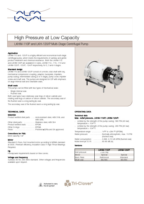
TECHNICAL DATAMaterialsProduct wetted steel parts...Acid-resistant steel,AISI316L andAISI329LOther steel parts:.........Stainless steel,AISI304Product wetted seals:......EPDM.Other O-rings:...........EPDM. Finish:................Polished≤32Ra and3A approved. Connctions for FSS:6mm tube/Rp1/8"MotorStandard C-Face,foot mounted motor according to NEMA standard at3500.Premium efficiency,insulation Class F.High Thrust Bearings Required.HpHorsepower requirements based on flow curves.Voltage and frequency3phase,60Hz,230-460v standard.Other voltages and frequencies available upon request.OPERATING DATATechnical dataMax.outlet pressure,LKHM-110/P,LKHM-120/P:-Limited by the strength of the pump casing:580PSI(40bar) temperature<104°F.-Limited by the strength of the pump casing:290PSI(20bar) temperature>104°F.Temperature range:........14°F to+284°F(EPDM).Water pressure:..........Normally atmospheric,max.15PSI(flushed seal).Water consumption:.......0.066-0.13US GPM(flushed seal) Noise level(at3.3ft:.......60-80dB(A).VersionsLKHM-110/P LKHM-120/P Inlet pressure>145PSI-Motor SpecialSpecial Back Plate Reinforced Standard Shaft seal SIC/SIC SIC/SICDimensions(in)LKHM-112MotorSize5Hp7.5Hp10Hp15HpB 4.50 5.507.008.25C 6.507.137.407.32E 2.99 2.99 2.99 2.99F8.358.359.139.13G10.3014.2014.2019.00H 5.51 5.51 5.51 5.51M7.508.508.5010.00Q8.8610.8711.1412.64R 3.39 3.39 3.39 3.39S12.0014.6016.1018.70U 5.83 5.83 6.61 6.61Weight(lbs)146.00197.00222.00315.00LKHM-114MotorSize15Hp20Hp25Hp30HpB8.2510.009.5011.00C10.5910.5911.7711.77E 6.26 6.26 6.26 6.26F9.1310.0810.8310.83G19.0019.0020.0020.00H 5.51 5.51 5.51 5.51M10.0010.0011.0011.00Q12.6412.6414.4914.49R 3.39 3.39 3.39 3.39S18.7019.4023.9023.90U 6.617.568.358.35Weight(lbs)347.00397.00478.00509.00LKHM-113MotorSize10Hp15Hp20HpB7.008.2510.00C9.068.988.98E 4.65 4.65 4.65F9.139.1310.08G14.2019.0019.00H 5.51 5.51 5.51M8.5010.0010.00Q12.8014.2914.29R 3.39 3.39 3.39S16.1018.7019.40U 6.61 6.617.56Weight(lbs)238.00331.00381.00LKHM-122/PSterling-motorhp(in)40/50/60A9.69B12.01C16.18E 3.27F min.10.24F max.15.16G21.02H10.43K26.5M12.52P min.26.02P max.30.94Q10.16R 4.45S27.56T7.87U8.66Z min.23.03Z max.27.95Weight(lbs)816/816/860LKHM-123/PSterling-motorhp(in)40/50/6075/100 A9.6915.31B12.0112.2/13.7 C18.4616.69E 5.557.76F min.10.2415.79F max.15.1618.19G21.0225.2H10.4310.43K26.515.98M12.5229.65P min.26.0231.93P max.30.9434.33Q12.4424.33R 4.45 4.45S27.5633/35T7.879.8U8.66Z min.23.0329.4/30.6 Z max.27.9531.8/33 Weight(lbs)853/853/8971274/1307LKHM-124/PSterling-motorhp40/50/6075/100 A9.6915.31B12.0112.2/13.7 C14.6516.69E7.767.76F min.10.2415.79F max.15.1618.19G21.0225.2H10.4310.43J12.5215.98K26.529.65P min.26.0231.93P max.30.9434.33Q20.6724.33R 4.45 4.45S27.5633/35T7.879.8U8.66Z min.23.0329.4/30.6 Z max.27.9531.8/33 Weight(lbs)891/891/9351274/1307Connections(in)LKHM-112,LKHM-113,LKHM-114Dl2"Tri-ClampDll1½"M l0.827M ll0.827VolumetricFlowOptionsA.Special motor for inlet pressure higher than 145PSI (only LKH-110).B.Motor for other voltage and/or frequencyC.Flushed shaft seal.D.Impeller with reduced diameter.E.Counter flanges,seal rings and bolts for flanged connections (industrial version).F .Product wetted seals of Buna (NBR),or Fluorinated rubber (FPM).G.Rotating seal ring of Silicon Carbide.H.Surface roughness,product wetted parts:unpolished,32Ra,micro inches (0.8mm),or higher finishes Note!For further details,see also instruction manual.OrderingPlease state the following when ordering:-Pump size.-Version,sanitary or industrial.-Connections.-Impeller diameter.-Motor size.-Voltage and frequency.-Flow,pressure and temperature.-Density and viscosity of the product.-Options.ESE00266ENUS 1505Alfa Laval reserves the right to change specifications without prior notification.ALFA LAVAL is a trademark registered and owned by Alfa LavalCorporate AB.©Alfa LavalHow to contact Alfa Laval Contact details for all countriesare continually updated on our website.Please visit to access the information direct.。
- 1、下载文档前请自行甄别文档内容的完整性,平台不提供额外的编辑、内容补充、找答案等附加服务。
- 2、"仅部分预览"的文档,不可在线预览部分如存在完整性等问题,可反馈申请退款(可完整预览的文档不适用该条件!)。
- 3、如文档侵犯您的权益,请联系客服反馈,我们会尽快为您处理(人工客服工作时间:9:00-18:30)。
AgilentT-13/4 (5 mm), T-1 (3 mm),High Intensity, Double Heterojunction AlGaAs Red LED LampsData SheetHLMP-D101/D105, HLMP-K101/K105DescriptionThese solid state LED lamps utilize newly developed doubleheterojunction (DH) AlGaAs/GaAs material technology. This LED material has outstanding lightoutput efficiency over a wide rangeFeatures• Exceptional brightness • Wide viewing angle• Outstanding material efficiency • Low forward voltage • CMOS/MOS compatible • TTL compatible • Deep red colorApplications• Bright ambient lighting conditions • Moving message panels • Portable equipment • General useof drive currents. The color is deep red at the dominantwavelength of 637 nanometres.These lamps may be DC or pulse driven to achieve desired light output.Package DimensionsA B CSelection GuideLuminous IntensityIv (mcd) at 20 mA2θ1/2[1]Package Package Description Device HLMP-Min.Typ.Max.Degree Outline T-1 3/4 Red Tinted Diffused D10135.270.0–65AD101-J00xx35.270.0–65AD101-JK0xx35.270.0112.865AT-1 3/4 Red Untinted Non-diffused D105138.0240.0–24BD105-M00xx138.0240.0–24BD105-NO0xx200.0290.0580.024BT-1 Red Tinted Diffused K10122.045.0–60CK101-100xx22.045.0–60CK101-IJ0xx22.045.070.460CT-1 Red Untinted Non-diffused K10535.265.0–45CK105-J00xx35.265.0–45CK105-KL0xx56.4110.0180.445CNote:1. θ1/2 is the off axis angle from lamp centerline where the luminous intensity is 1/2 the on-axis value.Part Numbering SystemHLMP - x x xx - x x x xxMechanical Option00: Bulk01: Tape & Reel, Crimped Leads02: Tape & Reel, Straight LeadsA1: Right Angle Housing, Uneven Leads, T1A2: Right Angle Housing, Even Leads, T1B1: Right Angle Housing, Uneven Leads, T-1 3/4B2: Right Angle Housing, Even Leads, T-1 3/4DD, UQ: Ammo PackColor Bin Options0: Full Color Bin DistributionMaximum Iv Bin Options0: Open (no max. limit)Others: Please refer to the Iv Bin TableMinimum Iv Bin OptionsPlease refer to the Iv Bin TableLens Type01: Tinted, Diffused05: Untinted, NondiffusedColor Options1: AlGaAs RedPackage OptionsD: T-1 3/4K: T-1Absolute Maximum Ratings at T A = 25°CParameter ValuePeak Forward Current[1,2]300 mAAverage Forward Current[2]20 mADC Current[3]30 mAPower Dissipation87 mWReverse Voltage (I R = 100 µA) 5 VTransient Forward Current (10 µs Pulse)[4]500 mALED Junction Temperature110°COperating Temperature Range-20 to +100°C Storage Temperature Range-55 to +100°C Wave Soldering Temperature [1.59 mm (0.063 in.) from body]250°C for 3 seconds Lead Solder Dipping Temperature [1.59 mm (0.063 in.) from body]260°C for 5 seconds Notes:1.Maximum I PEAK at f = 1 kHz, DF = 6.7%.2.Refer to Figure 6 to establish pulsed operating conditions.3.Derate linearly as shown in Figure 5.4.The transient peak current is the maximum non-recurring peak current the device can withstand without damaging the LED die and wire bonds. It isnot recommended that the device be operated at peak currents beyond the Absolute Maximum Peak Forward Current.Electrical/Optical Characteristics at T A = 25°CSymbol Description Min.Typ.Max.Unit Test ConditionV F Forward Voltage 1.8 2.2V I F = 20 mAV R Reverse Breakdown Voltage 5.015.0V I R = 100 µAλp Peak Wavelength645nm Measurement at Peakλd Dominant Wavelength637nm Note 1∆λ1/2Spectral Line Halfwidth20nmτS Speed of Response30ns Exponential TimeConstant, e-t/T SC Capacitance30pF V F = 0, f = 1 MHzRθJ-PIN Thermal Resistance260[3]°C/W Junction to Cathode Lead210[4]290[5]ηV Luminous Efficacy80Im/W Note 2Notes:1.The dominant wavelength, λd, is derived from the CIE chromaticity diagram and represents the color of the device.2.The radiant intensity, I e, in watts per steradian, may be found from the equation I e = l V/ηV, where I V is the luminous intensity in candelas and ηV isluminous efficacy in lumens/watt.3.HLMP-D101.4.HLMP-D105.5.HLMP-K101/-K105.Figure 3. Relative luminous intensity vs. dc forward current.Figure 4. Relative efficiency vs. peak forward current.Figure 7. Relative luminous intensity vs. angular displacement. HLMP-D101.Figure 8. Relative luminous intensity vs. angular displacement. HLMP-K101.Intensity Bin LimitsIntensity Range (mcd)Color Bin Min.Max.Red I24.839.6J39.663.4K63.4101.5L101.5162.4M162.4234.6N234.6340.0O340.0540.0P540.0850.0Q850.01200.0R1200.01700.0S1700.02400.0T2400.03400.0U3400.04900.0V4900.07100.0W7100.010200.0X10200.014800.0Y14800.021400.0Z21400.030900.0Maximum tolerance for each bin limit is ± 18%.Mechanical Option MatrixMechanical Option Code Definition00Bulk Packaging, minimum increment 500 pcs/bag01Tape & Reel, crimped leads, minimum increment 1300 pcs (T-1 3/4)/1800 pcs (T-1) 02Tape & Reel, straight leads, minimum increment 1300 pcs (T-1 3/4)/1800 pcs (T-1) A1Right Angle Housing, uneven leads, minimum increment 500 pcs/bagA2Right Angle Housing, even leads, minimum increment 500 pcs/bagB1Right Angle Housing, uneven leads, minimum increment 500 pcs/bagB2Right Angle Housing, even leads, minimum increment 500 pcs/bagDD Ammo Pack, straight leads in 2K incrementUQ Ammo Pack, horizontal leads in 2K incrementNote:All categories are established for classification of products. Products may not be available in all categories. Please contact your local Agilent representative for further clarification/information./semiconductors For product information and a complete list of distributors, please go to our web site.For technical assistance call:Americas/Canada: +1 (800) 235-0312 or (916) 788-6763Europe: +49 (0) 6441 92460China: 10800 650 0017Hong Kong: (+65) 6756 2394India, Australia, New Zealand: (+65) 6755 1939 Japan: (+81 3) 3335-8152 (Domestic/Interna-tional), or 0120-61-1280 (Domestic Only) Korea: (+65) 6755 1989Singapore, Malaysia, Vietnam, Thailand, Philippines, Indonesia: (+65) 6755 2044 Taiwan: (+65) 6755 1843Data subject to change.Copyright © 2004 Agilent Technologies, Inc. Obsoletes 5968-1440ENovember 12, 20045988-2230EN。
