Nero MediaStreaming for MCE 使用手册
nero使用说明

[autorun]
icon =cdrom.ico
然后再将一自己制作的cdrom.ico图标文件也拖入CD-R的根目录中一并刻录,以后在Windows 资源管理器中显示的就是cdrom.ico图标的样子了。
好好研究以下文章,就会明白的。
1.使用向导窗口
如果我们使用最新版的Nero,那它为我们提供了一个向导窗口,大家只要选择“开始”→“程序”→ahead Nero→Nero Express,就可以启动它。
在其中可以选择刻录机,也选择刻录盘片类型,然后顺着向导操作就可以了,非常方便。相信对于初学者很有帮助,在熟悉了它的操作之后,再切换到Nero-Burning Rom窗口操作肯定会更容易上手。
7.用Nero保存光盘信息
如果拿到一张光盘,很想将它保存下来,但发现通过直接拷贝法不行。可以用Nero的保存轨道功能把它保存下来:将CD光盘放入光驱后,然后选择“刻录机”菜单下的“保存轨道”命令,在打开的“保存轨道”窗口中选择欲保存的轨道。然择一个存放文件夹,Nero就会把选中光盘上轨道信息保存为NRG文件。
小提示
Nero-Burning ROM也支持把音乐CD转换成mp3Pro文件。不过,其内置的mp3Pro编码器在未注册之前最多只能够使用30次。
3.利用Nero批量转换mp3Pro文件
现在时下时尚给MP3文件减肥,而且越来越多的播放器支持mp3Pro格式的音乐了。但现成还是无法找到一个批量转换mp3Pro格式文件的转换软件(很多都提供转换功能,但一次只能够转换一首)。而Nero-Burning ROM中就带有mp3Pro编码器,利用它可以轻松把硬盘上的WAV文件批量转换成mp3Pro格式的文件。启动Nero后,选择“附加选项”→“文件编码”命令,在打开的“文件编码”窗口中单击“添加”按钮选择欲转换的文件,然后再在“输出格式”中选择“mp3PRO (*.mp3)”选项,再单击一下“目标文件夹”旁边的按钮选择一下输出文件夹,最后按下“继续”按钮即可批量转换。
nero7使用说明
用NERO7刻录DVD? 家用DVD机播放的那种(2010-07-01 16:47:59)转载标签:it如何刻录能够自动播放的DVD光盘1、文件整理建立一个文件夹,专门存放要刻录的影片DVDrip的avi文件和字幕文件、nfo文件,以及下面的文件。
2、提取WMedia Player 6.4播放器可以在电脑的软件目录中找到,一般在:C:Program FilesWindows Media Player路径下,只有5KB大小,最适合刻录进CD-R光盘中作为播放器使用。
因为这个播放器不需要安装,是Windows系统的自带播放器,而且体积相当小。
将这个文件拷贝到存放影视文件的文件夹中。
当然,你也可以使用Media Player Classic作为播放器使用,这个播放器也是不需要安装就可以使用的,体积约700k。
3、打开资源管理器的显示扩展名的功能点击资源管理器菜单的“工具”-->“文件夹选项”,选择“查看”选项卡,取消“隐藏已知文件类型的扩展名”的选项前的对号。
4、建立autorun控制程序在存放影视文件的文件夹中右键新建一个文本文件,内容如下:[AutoRun]open=mplayer2.exe 电影文件名icon=mplayer2.exe,0其中,“电影文件名”请自行修改为你要刻录的影视文件的avi文件的文件名,且必须为包含.avi扩展名的格式。
保存此文件,关闭后修改文件名为“autorun.inf”5、刻录将刚才的保存有autorun.inf 、mplayer2.exe、电影文件、字幕文件等的文件夹中的所有文件放在光盘的根目录下一起刻入光盘。
这样你再次插入此光盘的时候,电脑就会自动播放了。
家用DVD是可以读DVD-R盘的。
帮你查了一下资料:刻录小知识:1.+R与-R 区别:规格制定者不同:具有技术优势的厂商不同寻址的方式不同:DVD-R 使用低频寻址方式,DVD+R 使用高频摆动沟槽的相位调变寻址方式所需的母盘不同:染料一般没有差别生产的过程不同:DVD-R 在成型后,需要用专用的预写机预写,DVD+R 则不需要2.+R与-R 特性:+R 是利用相位变换来记录数据,这种方式有助于提高盘的的刻录速度,-R 是利用打孔的方式来记录数据,理论上刻录速度的提高会困难一些,但是其刻录兼容性会高于+R 。
洛雷斯4通道LCDDVR与预装硬盘的快速设置指南说明书
Now with ArrayQuiCk STaRT GuiDEW W W.L O R E X C C T V.C O MSystem Contents:PaCkaGE CONTENTS, iNSTaLLaTiON GuiDE, NaViGaTiON & CONTROLSTimeunder 30 minutes under 15 minutes under 60Hand ToolsHardwareSkills - IntermediateadvancedSkills - AdvancedIntermediate advanced☠ aTTENTiON:Broadband router and computers are required for local and remote monitoring iNSTRuCTiONS:for detailed setup information, please refer to your user’s manual.SOFTWaREREQuiREMENTS:for Lorex client software requirements, please refer to Lorex client software ☠ aTTENTiON:*number of channels,cameras and hard drive capacity may vary by model. check your MOUSE:LEFT BUTTON• Double click in viewing mode to display camera in RECOMMENDED FOR EaSY uSE aND NaViGaTiONRECOMMENDED FOR uSE FROM a DiSTaNCE*STEP 1 - SET uP YOuR MONiTOR FiRSTconnect the first camera to the cH1 input. follow the same steps to connect the additional cameras.CONNECT CaMERaS TO THE MONiTOR:connect one end of the ethernet cable to one of the router’s (not included) Lan ports and the other end to monitor’s network port located at the bottom of the monitor. see picture below showing a generic Lan/wan connection.CONNECT THE ETHERNET CaBLE:connect the mouse to the ps2 port of the monitor.CONNECT THE MOuSE:WAN (WIDEAREA NETWORK)LAN (LOCAL AREA NETWORK)TO YOUR COMPUTERTO YOUR MONITORBACK OF THE ROUTER SHOWNMOuSE CONTROL aVaiLaBLE1. Connect the Female BNC end of the supplied 60’ extension cable to the camera. Connect the male Power end of the extension cable to the camera.2. Connect the Female end of the supplied 60’ extension cable to an open BNC camera input on the back of the System. Connect the female Power end of the extension cable to one of end of the 4 in one power adaptor.1connect one end of the power adaptor to the monitor, the other end to an electrical outlet. this unit powers on once it is plugged in to the power outlet.CONNECT POWER CaBLE:IMPORTANT NOTE: The ends of the extension cable are NOT the same - one end has a Male power port, and the other has a Female power port. Before permanently running the Camera Extension Cable, make sure that the cable has been oriented between the Camera and the unit correctly34521. access the main menu setup screens, and navigate to the main menu - externaL device - tcp/ip setup - ip setup option.2. record the mac address of your system. this information is necessary for the ddns setup process.3. confirm that the dHcp mode is set to automatic. this will allow your system to lease an ip address from your router. if the system is not set to automatic, change the setting in the dHcp setup menu and click detect ip.4. the ip port is 50000 by default.STEP 2 - SET uP LOCaL ViEWiNG ON YOuR PCRETRiEVE SYSTEM iNFORMaTiON:RECORD THE iP aND MaC aDDRESSES iN THE SECTiON BELOW:note: the system will lease networking information from your router. if you wish to set your information manually, then set the dHcp mode to manuaL. please consult your Hardware manual for further menu options.insert the Lorex cLient 2.2 software cd into your local computer’s cd rom drive and proceed with the installation.iNSTaLL SOFTWaRE:(on your local computer for local viewing)follow the installation screens to complete Lorex client 2.2 software installation.LOREX CLiENT 2.2 SOFTWaRE:(on your local computer for local viewing)for Lorex client software requirements, please refer to the software user manual.12345123close the cd menu screen. a Lorex client icon will appear on your desktop.LOREX CLiENT 2.2 SOFTWaRE:(on your local computer for local viewing)double-click the Lorex cLient 2.2 software icon on your desktop to run the program.RuN THE LOREX CLiENT 2.2 SOFTWaRE:(on your local computer)4THIS STEP RELATES TO REMOTE VIEWING OVER THE LAN (LOCAL AREA NETWORK)STEP 2 - SET uP LOCaL ViEWiNG ON YOuR PCCONTiNuEDCongratulations! Youhave completed Stepsuccessfully. You cannow view and playbackimages on your localcomputer over the LocalArea Network (LAN).5ADMIN681. once you see the registered site, press the save button.2. click the oK button. you will be asked to key in the user id andpassword.user id: By default is adminpassword: Leave it blankLOREX CLiENT 2.2 iRS SETuP - REGiSTERiNG SiTE(on your local computer for local viewing)129123457STEP 3 - SET uP iNTERNET REMOTE SECuRiTY MONiTORiNGvisit /support to view tHe router configuration guideCOMPLETE NEW aCCOuNT iNFORMaTiON:1. for product License select the L15Ld420 / L17Ld420 series from the drop down menu.2. for product code enter the monitor’s mac address (recorded in step 2, section 1).3. for urL reQuest enter a unique urL name (e.g. tomsmith). note: urL name should not be more than 15 characters.12312345STEP 3 - SET uP iNTERNET REMOTE SECuRiTY MONiTORiNGENTER DDNS SET-uP ON YOuR SYSTEM:6• set the ddns enaBLe to on• domain - enter the ddns domain name from the registration email sent to you(e.g. )• user name - enter the user name from the registration email sent to you (e.g. tomsmith)• password - By default is left blank• ddns status - indicates the status of ddns connection.• click on register - this will register your system with Lorex ddns. if the information you haveENaBLE DDNS SETTiNGS:788follow the installation screens to complete Lorex client 2.2software installation.LOREX CLiENT 2.2 SOFTWaRE:(on your remote computer)123459close the cd menu screen. a Lorex client icon will appear on your desktop.LOREX CLiENT 2.2 SOFTWaRE:(on your remote computer for remote viewing)double-click the Lorex cLient 2.2 software icon on your desktop to run the program.RuN THE LOREX CLiENT 2.2 SOFTWaRE:(on your local computer)10CONTiNuEDSTEP 3 - SET uP iNTERNET REMOTE SECuRiTY MONiTORiNGCONTiNuEDCongratulations! You have completed Step successfully. You can now view and playback images on your remote computer over the internet.click on the “registering site” button to add a new site to your system.LOREX CLiENT 2.2 iRS SETuP - REGiSTERiNG SiTE(on your remote computer for remote viewing)1. once you see the registered site, press the save button.2. click the oK button. you will be asked to key in the user id and password. user id : By default is admin password : Leave it blankLOREX CLiENT 2.2 iRS SETuP - REGiSTERiNG SiTE(on your remote computer for remote viewing)121. click the H.264 viewer screen (as shown in the picture) and press the connect button to connect to the remote Live site.ViEW CaMERaS REMOTELY:(on your remote computer for remote viewing)123451112131415RECOMMENDED TiPStilt the monitor up to loacte your monitor’s connections.LOCaTE MONiTOR CONNECTiONS:DiSPLaY CONFiGuRaTiON / FuNCTiON iCONSthe system provides a storage calculator to calculate the amount of recording time available on your Hard drive, based on the system recording settings.click on the menu icon to enter main menu. on the main menu, click on the record menu. on the record menu, click onrecord set up.RECORD SETuP (storage calculator):1. [QuaLity]: set up the recording picture qualityQuality level: normal / High / Highest. data size of image in paL system is a little bigger than ntsc system, but the total recording time is same.2. [frame rate]: adjust recording frame rate.3. [pre aLarm record]: displays the amount of time included from the pre recording (in seconds).4. [Hdd remaining]: indicates Hdd capacity remaining by size (gB). / indicates total Hdd capacity (gB).5. [remain time]: indicates Hdd capacity remains by time. (d- days, H- hours, m- minutes).1234510formatting tHe new Hard drive:the new Hard drive must be formatted. if a new Hard drive is detected, the system will prompt you to format the drive. please refer to the system’s user manual for Hdd installation.HDD iNSTaLLaTiON:the system comes with a pre-installed Hard drive, however the unit will work with a replacement single sata Hard drive (up to 500gB).note: make sure that the system is off and the power cable has been disconnected before changing the Hard drive. for detailed instructions, check the user’s manual.TiP ON CaMERa MOuNTiNG:note: test the cameras prior to selecting a permanent mounting location by temporarily connecting the cameras and cables toyour system.RECOMMENDED TiPS CONTiNuEDnote: you must have an active internet connection to the system to be able to perform remote viewing or playback. remote access is dependant on your connection speed, internet traffic and other network factors - the speed is normally 1~2 fps (frames per second). this may impact the audio and ptZ functions.for faster playback, it is recommended to download previously recorded video using the backup function and play it back using Backup player 2.2 software - refer to the user manual for details. regardless of the network playback speed, video is being recorded on your system in real time, and can be viewed when you are at the system or through the backup player.TiP ON REMOTE ViEWiNG aND PLaYBaCk OVER THE iNTERNET (WaN):11 LOREX CLiENT 2.2 iNTERNET REMOTE SOFTWaRE (iRS)1. LOREX iRS SETuPsetting up irs is necessary in order to use the H.264 viewer.2. LOREX H.264 ViEWERremote monitoring software recommended for internet remote monitoring. H.264 video compressiontechnology allows for efficient data transfer over the internet. you can view your system remotely whileconsuming less bandwidth.3. LOREX SEaRCHsearch for recorded data to playback from a remote location.4. LOREX BaCkuPcreate a backup of your recorded data from a remote location.5. LOREX PLaYERplayback data that has been backed up either from the system using a usB thumbdrive or from thebackup software.6. LOREX REMOTE SETuPconfigure the system remotely (e.g. change recording settings or schedules).1PRODuCT SuPPORT it’s all on the Web for detailed setup information, please refer to your user’s manual. for additional information about determining your ip address, configuring your router, and port forwarding, please visit our website /support and clickconsumer guides section or view guides from the cd included with your system.emailsupport:*********************toll free technical support :north america: 1-888-42 Lorex (1-888-425-6739)toll free technical support :international (outside of north america): +800-425-6739-0(example: from the uK, dial 00 instead of +)Lorex international website - 。
SyncUP使用手册
根据从 Dolby Laboratories 取得的授权制造。“Dolby”和双 D 符号是 Dolby Laboratories 的商标。属于未公开发布的机密作品 。版权所有 1998-2009 Dolby Laboratories。保留所有权利。 根据取得的授权制造,符合以下美国专利以及其他美国和世界范围已发专利和待批专利的规定:5,451,942;5,956,674;5,9 74,380;5,978,762;6,487,535。DTS 及其符号是注册商标,DTS Digital Surround 和 DTS 徽标是 DTS, Inc. 的商标,版权 所有 © DTS, Inc.。保留所有权利。
52
52 53 53
4
创建和编辑
创建幻灯片 个性化幻灯片 创建照片和视频专辑 创建播放列表 照片的常规编辑
55
55 56 58 59 60
4
5
从光盘和设备导入
设置设备 从音频 CD 翻录
61
61 63
6
发布
刻录到光盘 上载到社区
64
64 65
5
1
祝您有个成功的开始
关于此应用程序
SyncUP 桌面应用程序让您可以在以前从未到过的地方享受移动同步体验。利用 SyncUP,您 可以方便地播放音乐文件,并管理和创建播放列表。还可以方便地使用内置播放器在计算机上 播放照片和视频。通过利用 iTunes 资料库整合功能,您无需同时运行两个应用程序,便可以 播放 iTunes 播放列表和管理媒体内容。 SyncUP 还允许您创建自己的照片和视频专辑合集。您可以在幻灯片放映模式下预览所有合集。 可以优化手机或相机中不够完美的照片或视频。还可以预编辑 PC 上的照片或原始视频片断并 按照您想要的方式获得它们。 SyncUP 可自动将视频压缩成仅占其原始存储空间大小一部分的剪辑,并将原始分辨率降低至 专用于在手机上观看的视频分辨率,还可将视频的编码格式转换成您手机支持的格式。您不需 要考虑文件格式、编码解码器和视频分辨率。 您还可以翻录音乐 CD,并与您拥有的其他移动设备共享,使您无论身处何地都可以享受音乐 带来的愉悦。您还可将高品质的 AVC 和 MPEG- 4 内容快速上传到您最喜欢的网络社区, 与家人和朋友分享。
Nero 7说明手册

Nero 7 Premium 7.2.3.2b感谢tienan投递使用Nero 可让您以轻松快速的方式制作您专属的CD 和DVD.不论您是所要刻录的是资料CD、音乐CD、Video CD、Super Video CD、DDCD 或是DVD,所有的程序都是一样的.使用鼠标将文件从文件浏览器拖曳至编辑窗口中,开启刻录对话框,然后激活刻录作业.7.2.3.2b更新情况:- Nero Burning ROM and Nero Express crashed after the DEMO version had expired.- Bad, scratchy sound when encoding files to mp3 using the 'standard' settings- Multisession was not automatically selected when burning to the image recorder- UNC support of Nero did not work anymore, so continuing a multi session CD with UNC paths did not work- Nero Burning ROM did not use the selected partition to create a boot CD- Nero Express crashed under Windows 98 when adding protected WMA files to a compilation- Nero Burning ROM had graphical problems under Windows 98 when changing the menu options any kind of animation- It was possible to select the ISO file system view in the folder panel of the compilation, although a UDF compilation was chosen- Error message was shown when starting to convert Audio CDs to Nero Digital Audio官方中文版,不带雅虎工具条。
Nero刻录软件使用教程及各种光盘刻录解决方法
Nero刻录软件使用教程及各种光盘刻录解决方法(图文)文章来源:网络阅读: 632次更新时间:2010-8-13 21:26:47“刻好光盘后不能光驱启动怎么办?”解决办法:1。
必须按照光盘制作方法正确操作,确保制作的光盘镜像ISO能用虚拟机加载成功进行安装。
2。
必须正确使用Nero刻录软件的选项,并配置相应的刻录机(CD或DVD)。
以下这篇《刻录光盘不求人——Nero刻录軟件使用教程》节选,仅供参考。
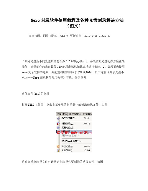
映像文件(ISO)的刻录打开NERO主界面,点击主菜单里的刻录器中的刻录映像文件,如图这时会弹出选择文件对话框让你选择你要刻录的映像文件,如图单击刻录即可只要是对刻录机稍稍有所了解的朋友相信都不会对NERO这一款刻录软件感到陌生,NERO是一款德国公司出品的非常出色的刻录软件,它支持数据光盘、音频光盘、视频光盘、启动光盘、硬盘备份以及混合模式光盘刻录,操作简便并提供多种可以定义的刻录选项,同时拥有经典的 Nero Burning ROM 界面和易用界面 Nero Express,如图视频编辑与刻录可以说是一对密不可分的兄弟,因为视频编辑制作最终的结果大多是把视频文件刻录到光盘做成VCD、DVD的,但是很多对视频编辑感兴趣的朋友对于刻录还只是停留在初级阶段,只知道刻刻数据和VCD其它就不甚了解了,下面我就以用得最广泛的NREO软件作为工具向朋友们说说我的刻录心得,以供大家参考。
现在NERO最新版本支持雅马哈刻录机的 [email=DiscT@2]DiscT@2[/email] 功能。
它可让您以轻松快速的方式制作您专属的 CD 和 DVD.不论您是所要刻录的是资料CD、音乐 CD、Video CD、Super Video CD、DDCD 或是 DVD,所有的程序都是一样的,使用鼠标将档案从档案浏览器拖曳至编辑窗口中,开启刻录对话框,然后激活刻录。
NREO有独特的文件侦测功能,它可以让您可以放一百二十个心,因为您几乎不可能出错。
NERO使用教程-详解(图)
选中某个轨道之后,可以点击下面的“播放”按钮预览视频文Байду номын сангаас。
都调整完毕以后,再编辑一下光盘属性--右键点击左上窗口那个光盘图标,选“属性”。
需要着重说明的是“菜单”设置页。如果勾选“启动菜单”项,那么这张碟片插入VCD播放机之后将出现一个启动选单(菜单)。这个可以根据具体情况决定。如果刻录的是整盘只有一段的电影碟,就没有必要弄什么选单,因为没有什么需要选择的。倘若刻录的是象本例这样存在多个视频段落的碟片,就可以根据自己的喜好决定是否加启动选单。
熟悉了刻录数据光盘,让我们再来了解用Nero如何刻录其他格式的光盘:选择“文件-新建”,在出现的菜单中就可以选择我们要刻录的各种类型的CD了。包括音频CD、混合模式CD、CD拷贝、VCD、超级视频CD、只读CD(启动)等。
选择“VCD”可以制作VCD光盘。通常来说,我们在刻录VCD光盘时是把该光盘用于一般的家用VCD机上,为了使光盘符合VCD机的标准。Create Standard Compliant CD“创建符合标准的光盘”是必须勾选的。由于家用VCD机大都只能认ISO 9660的国际标准,因此在这里我们要ISO 1级的文件/目录名长度和ISO 9660的字符集,并且不要选取“放宽ISO限制”。这一切都设定好后就可以按“新建”按钮进入VCD节目的编辑了。Nero可支持的影像文件格式有.dat和.mpg,但都必须是标准的MPEG-1编码。我们要注意的是把影像文件拖到光盘面板下方的音轨窗口,而不是完成刻录后存放.dat文件的mpegav目录,这点很重要!
然后点击右上的“新建”按钮
在右边的文件浏览器窗口中,找到已经准备好的视频文件。选中之后,用鼠标拖拽到左下的视频轨道窗口中。
NOONTEC A6 Pro多媒體播放機 说明书

6
按此鍵可實現向下的功能,在檔目錄或設置功能表中,可向 下移動游標,在圖片放大後,可向下移動圖片。播放視頻檔 時,可對外掛的字幕位置進行向下移動 按此鍵進行向左操作,在檔目錄中,可返回上級目錄,設置 功能表中向左移動游標,在圖片放大後,向左移動圖片。播 放視頻檔時,可對外掛的字幕進行縮小 按此鍵實現向右功能,在設置功能表中向右移動游標,在圖 片放大後,向右移動圖片。播放視頻檔時,可對外掛的字幕 進行放大 按此鍵,從當前播放狀態向後快退, 再重複按此鍵,選擇快退速度 按此鍵,從當前播放狀態向前快進, 再重複按此鍵,選擇快進速度
包裝清單..................................................... 3 前視圖 ........................................................ 4 側視圖 ........................................................ 4 後視圖 ........................................................ 5 遙控器按鍵說明 ......................................... 6
基本操作 ................................................................................... 9
播放前的準備 ............................................. 9 網路共用多媒體檔.................................... 13
Infineon iMOTION MCETool V2 用户手册说明书

User Manual Please read the Important Notice and Warnings at the end of this document <Revision 1.4><2017-07-27>AN2017-02MCETool V2User ManualMCETool V2User ManualiMOTION ™programming,debugging and tuning toolQuality requirement category:IndustryFeatures•Programming of RAM,Flash and OTP memory for IRMCKxxx and IRMCFxxx devices•Debugging via standard JTAG interface•Tuning of motor parameters via virtual UART•All interfaces are galvanically isolated• 3.3VDC output voltage to target•Internal generation of OTP programming voltage•USB interface to PC for power and data•Ships with all required cablesSupported Devices•iMOTION ™IRMCK099•iMOTION ™IRMCx100series•iMOTION ™IRMCx300series•iMOTION ™2.0Devices (virtual UART only)DescriptionMCETOOLV2(formerly ‘IR Cable V2’)is designed to program and debug IRMCK099/IRMCx100/IRMCx300series iMOTION ™motor control ICs on the user’s target board (final application board)or on IRMCx evaluation boards.The MCETOOLV2can also be used for motor and inverter board parameter tuning via the UART to USB interface.Infineon provides the respective PC tools (MCEProgrammer &MCEDesigner)for download on the /imotion-software web page.Tools are delivered as a part of Installer package (e.g.“99Series Installer”and “100Series Installer”)Table of contentsTable of contents1Introduction (3)2Software installation for MCETOOLV2 (5)2.1MCE Programmer,MCE Designer and CP210x driver installation (5)2.2Software installation step by step (6)3Getting Started (8)3.1Using MCETOOLV2with MCE Programmer (8)3.1.1PC port configuration (8)3.1.2Target device programming (9)3.2Using MCETOOLV2with MCE Designer (10)3.2.1PC port configuration (10)3.2.2Programming target device (11)1IntroductionMCETOOLV2(in some older documents named ‘IR Cable V2’)is designed to program IRMCK099/IRMCx100/IRMCx300series digital motor control ICs on the user’s target board (final application board)or on corresponding Evaluation Kits,to enable engineers to design the application code during development.MCETOOLV2contains the following basic configuration and functions:•Power:5V DC power supply (Powered through USB Mini B type interface)•PC interface:USB to virtual communication port with baud rate of up to 256Kbps•Isolated 3.3V DC Output for target•Isolated output interface:o 8Pin JTAGo 4Pin UART Figure 1Picture of MCETOOLV2Function description1.Isolated UART port2.Isolated JTAG port3.Green LED1:Indicates when Vpp is enabled during programming the target4.Yellow LED:When blinking indicates that MCETOOLV2is powered and MCU is working.5.Switch SW1:Provides 3.3V to target board,and provides program voltage Vpp when programming OTP.6.PC USB cable port for UART operation7.PC USB cable port for JTAG operation8.Red LED6:Indicates presence of 5V USB power supply.When MCETOOLV2connects to PC,this LED shows that the MCETOOLV2has been powered from 5V USB power.42135678To use as an isolated USB to UART converter,PC USB cable plugs in to“USB-UART”,and the UART output port is used.The pinout for UART connector(J2)is as shown in figure belowFigure2UART Connector pinoutTo use as an isolated USB to JTAG converter,PC USB cable plugs in to“USB-JTAG”,and the JTAG output port is used.The pinout for JTAG connector(J3)is as shown in figure belowFigure3JTAG Connector pinoutSwitch SW1is used to power target from isolated DC-DC converted on MCETOOLV2.If switch is in upward position,target is powered from MCETOOLV2and if it’s in downward position,target is powered from external source.The MCETOOLV2is supported by following software tools:•MCE Programmer(v3.0.1.9and above)•MCE Designer(v1.2.0.0and above)2Software installation for MCETOOLV2MCETOOLV2is supported by MCE Programmer as well as by MCE Designer and needs CP210x virtual com port drivers to communicate with PC.The installation procedure for MCE Programmer,MCE Designer and CP210x virtual com port drivers is as follows.2.1MCE Programmer,MCE Designer and CP210x driver installationMCE Programmer,MCE Designer and CP210x drivers are available for download from the Infineon website and are also part of the software package Infineon-99series-kit-mce-installer-SW-v02_02-EN.exe(or higher version)in “99Series Installer”or Infineon-100serieskitmceinstaller-SW-v03_05-EN.exe(or higher version)in“100Series Installer”which contains the following support items for MCETOOLV2:•Pre-Requisite software•MCE Programmer software•MCE Designer software•CP2102driver.Note:The following description is based on the use of the all-in-one installation package“Infineon-99series-kit-mce-installer-SW-v02_02-EN”.The installation procedure might differ slightly ifindividual installation files are used for the software tools above.2.2Software installation step by stepStep1:Double click the“Infineon-99series-kit-mce-installer-SW-v02_02-EN.exe”file.Installation process will check if the PC already has the software:“Microsoft Visual C++Runtime11.0”and“ Framework 3.5”or above version.If there is no such software,the installation will install them,otherwise it will go to the next step.Figure4Pre-Requisites software installationStep2:After the pre-requisite software installs,it will install MCE Designer,MCE Programmer and other packaged application software.Figure5MCE Designer,MCE Programmer and other software installationPress“Next”to select the install path,the default path is C:\Program Files\iMotion.This will overwrite previously installed files.The user can select a different path to preserve an earlier version of Infineon-99series-kit-mce-installer-SW-v02_02-EN.Then press“Next”and start the Infineon-99series-kit-mce-installer-SW-v02_02-EN software installation.Step3:The driver installation dialog will launch during Infineon-99series-kit-mce-installer-SW-v02_02-EN installation.If the PC has installed the CP210x chip driver before,press“Cancel”to cancel the operation, otherwise follow the prompt to finish unpacking and installing the driver.Figure6C210x chip driver installationsStep4:After CP210x chip driver installation the following dialog“IRMCK099Series iMotion Design Kit Support”successfully installed will appear.Check/Uncheck boxes to visit iMotion support site and view release notes and press“Finish”to exit the installation wizard.Figure7Installation completed dialog3Getting Started3.1Using MCETOOLV2with MCE Programmer3.1.1PC port configurationWhen MCETOOLV2is used for the first time or the COM port number has changed,configure the connection port and the baud rate.If there is no connection or the configuration has problem,MCE Programmer will prompt warning information.Launch MCE Programmer and select“Tools—>IR Cable V2Serial Port Setup”.Choose the right serial port and set the baud rate to“57600bps(IRCable V2default)”.Figure8Configuring the connection portNote:If there is no MCETOOLV2connection to the PC or the configuration is mismatched,the following error messages will appear.Please reconfigure the port settings.Figure9Open COM port failed/Port configured incorrectly3.1.2Target device programmingSelect desired operation for MCETOOLV2from drop-down list,select.bin file and click“Download”or“Program +Verify”button(depending upon desired operation)Figure10Select desired programming optionAnd wait for desired operation to finish.Figure11Programming completeSwitch SW1is used to power target from isolated DC-DC converted on MCETOOLV2.If switch is in upward position,target is powered from MCETOOLV2and if it’s in downward position,target is powered from external source.When Programmming OTP,switch in upward position is required.3.2Using MCETOOLV2with MCE Designer3.2.1PC port configurationLaunch MCE Designer,open desired configuration file(with extension.irc)Figure12Configuration file selectionHighlight or click child window with title“System–XXX.irc”and select“Preferences—>Connection”.Select proper com port from drop down list and press“OK”button.Figure13Com port selection3.2.2Programming target deviceHighlight or click child window with title“System–XXX.irc”and select“Tools—>Load Target”.Select desired firmware file(with.bin extension)using“Browse..”button,press“Open”button in file selection dialog and then “OK”button in“Load Target”dialog.Figure14Firmware file selectionWait for programming to finish.Figure15Programming in progressFigure16Programming completeWhen configuration file is loaded or MCETOOLV2is used for the first time or the COM port number has changed, configure the connection port.If there is no connection or the configuration has problem,MCE Designer will prompt warning information.In this case,highlight or click child window with title“System–XXX.irc”and select“Preferences—>Connection”.Select proper com port from drop down list and press“OK”.Revision historyRevision historyMajor changes since the last revisionVersion number Revision date Revision description1.32017-03-01First Release1.42017-07-27 1.Box figure updated2.Document title updated3.Software download link updated4.Interface illustration updatedTrademarks of Infineon Technologies AGµHVIC™,µIPM™,µPFC™,AU-ConvertIR™,AURIX™,C166™,CanPAK™,CIPOS™,CIPURSE™,CoolDP™,CoolGaN™,COOLiR™,CoolMOS™,CoolSET™,CoolSiC™, DAVE™,DI-POL™,DirectFET™,DrBlade™,EasyPIM™,EconoBRIDGE™,EconoDUAL™,EconoPACK™,EconoPIM™,EiceDRIVER™,eupec™,FCOS™,GaNpowIR™, HEXFET™,HITFET™,HybridPACK™,iMOTION™,IRAM™,ISOFACE™,IsoPACK™,LEDrivIR™,LITIX™,MIPAQ™,ModSTACK™,my-d™,NovalithIC™,OPTIGA™, OptiMOS™,ORIGA™,PowIRaudio™,PowIRStage™,PrimePACK™,PrimeSTACK™,PROFET™,PRO-SIL™,RASIC™,REAL3™,SmartLEWIS™,SOLID FLASH™, SPOC™,StrongIRFET™,SupIRBuck™,TEMPFET™,TRENCHSTOP™,TriCore™,UHVIC™,XHP™,XMC™Trademarks updated November2015Other TrademarksAll referenced product or service names and trademarks are the property of their respective owners.。
罗杰流媒体播放器快速入门指南说明书

STEP 5:On-screen setupand activationFollow the instructions onyour TV screen.Activate your streamingplayer by using yourcomputer or smartphoneto link to a Roku account.Common questionsWhy do I need to create a Roku account?Before you can start streaming, channels must be downloaded and installed onyour streaming player. Y ou’ll need a Roku account to access the Roku ChannelStore, manage your subscriptions, view your purchase history, and add a paymentmethod. For more info, visit /whyaccountWhy do I need to enter a credit card?Saving a payment method makes it easy to rent or buy movies on demand,subscribe to popular services, and enroll in free trials. Charges will not be madewithout your authorization. For more information, visit /paymenthelpWhat should I do if my streaming player is not connecting to my wireless network?Y our streaming player connects to your wireless network the same as your laptop orsmartphone. If these other devices can access the internet, then your streaming playershould be able to do the same. Make sure to select the same network name, and enterthe same password you use with the other devices. Remember that passwords are case-sensitive and easy to enter incorrectly. For more help, visit /wirelessCan I take my Roku streaming player with me when I travel?Y es. Y ou can bring your streaming player and watch your favorite entertainmentwhen you travel. Remember to also bring a USB power adaptor (like your phonecharger), remote, and any cables you use to connect your streaming player athome. Make sure your destination has a good internet connection. Y ou may need acomputer or smartphone to help connect your streaming player to a new wirelessnetwork. For more details, visit /travelwithrokuNOTE: Roku does not charge for activation support – beware of scams.4What’s includedSTEP 1:Connect to TVHDTVs:Plug your streaming player into an HDMI® port on your TV . 4K and HDR TVs:T o stream 4K or HDR, choose an HDMI port that supports HDCP 2.2.For help determining which port supports HDCP 2.2, visit /hdcpSTEP 2:Connect to powerFor the best streaming experience, use the included USB power cable, power extender cable and power adaptor to connect your streaming player to a wall outlet.STEP 3:Power on TV and select inputUse your TV remote to power on your TV ands elect the input you used to connect your streaming player.For help on how to select the correct input, visit /selectinputSTEP 4:Insert batteriesOn the back side of the remote, slide open the battery cover . Insertincluded Duracell® batteries placing the negative (-) ends in first.Y our remote should pair with your streaming player automatically. For help pairing your remote, visit /remotehelpDoesn’t fit?Order a free HDMI extender cable at /HDMIOr use the included USB power cable to connect to the USB port on your TV .NOTE: See a red light on your streaming player? That means theUSB port on your TV is not providing enough power. Use the included power adaptor instead. For help, visit /lowpowerRoku®Streaming Stick®+USB power cablewith long-range wireless receiverPower adaptorTwo AAADuracell® batteriesRemoteUSB power extender cableFREE。
思科 MCE 平台使用指南说明书
如何使用MY CISCO ENTITLEMENTS (MCE)適用於MCE 使用者的逐步指南2020 年8 月前言目的對象文件更新時間2020 8© 2020 思科和/或其附屬機構。
保留所有權利。
一種帳戶類型,可讓您在同一個位置,輕鬆跨組織檢視、儲存及管理所有資產和權利,思科客戶和合作夥伴獲得的下列權限:使用權限、技術支援權限、軟體下載權限、授CCO ID 網域代表企業或組織在網際網路上的身分,以電子郵件地址詞彙表字詞定義智慧型帳戶(SA)也可用來整合使用者的存取管理作業。
虛擬帳戶(VA)SA 內的子資料夾,有助於您在內部整理資產和權利。
資產硬體/裝置、軟體、訂閱和服務。
權利權管理權限、軟體版本升級權限、硬體更換權限、內容存取權限等等。
CCO ID 是用於 網站的個人登入資訊。
您可以使用CCO ID 報名訓練課程、活動、計畫和促銷活動,以及存取其他工具和內容。
網域**************為例,網域是「 」。
全部檢視| 全面管理| 全方位保障使用者在MCE 中可查看的資產和權利個人化檢視會有所有不同,視其個別的SA 和VA 存取權限而定。
使用您的CCO ID 和密碼登入客戶名稱+ 標誌預設登陸頁面為「Account Overview」如果您可以存取多個SA ,則該平台將:1.顯示所有SA 清單及其SA 網域識別碼(首次登入時)附註:智慧型帳戶選取項目已儲存,下次登入時將設為預設值登入後,您可以2.選取其中一個SA ,以查看該SA 的資產。
3.按SA 名稱/帳戶網域識別碼搜尋SA ,或從清單中選取。
4.在所選的SA 中選取VA ,以查看該VA 的資產。
設定檔與智慧型帳戶不相符13241234已經有智慧型帳戶?已經有智慧型帳戶?設定檔與智慧型帳戶不相符如果您沒有智慧型帳戶的存取權,且您的電子郵件網域也不符合思科資料庫內的任何現有SA 網域,您可以:1.建立新的智慧型帳戶。
2.在不用智慧型帳戶的情況下繼續前往入口網站。
新颖通道微音频预置器、EQ、压缩器、SILK操作手册说明书

Newton ChannelMic Preamp, EQ, Compressor, SILKOperations Manual1.Read these instructions.2.Keep these instructions.3.Heed all warnings.4.Follow all instructions.5.Do not use this apparatus near water.6.Clean only with a dry cloth.7.Do not block any ventilation openings. Install in accordance with themanufacturer’s instructions.8.Do not install near any heat sources such as radiators, heat registers,stoves, or other apparatus (including amplifiers) that produce heat.9.Do not defeat the safety purpose of the polarized or grounding-typeplug. A polarized plug has two blades with one wider than the other.A grounding-type plug has two blades and a third grounding prong.The wide blade or the third prong are provided for your safety. If theprovided plug does not fit into your outlet, consult an electrician forreplacement of the obsolete outlet.10. Protect the power cord from being walked on or pinched particularly atplugs, convenience receptacles, and the point where they exit from theapparatus.11. Only use attachments/accessories specified by the manufacturer.12. Use only with a cart, stand, tripod, bracket, orthe apparatus. When a cart is used, use cautionavoid injury from tip-over.13. when unused for long periods of time.14. Refer all servicing to qualified service personnel. Servicing is requiredwhen the apparatus has been damaged in any way, such as power-supply cord or plug is damaged, liquid has been spilled or objects have fallen into the apparatus, the apparatus has been exposed to rain ormoisture, does not operate normally, or has been dropped.15. This apparatus shall not be exposed to dripping or splashing, and noobject filled with liquids, such as vases or beer glasses, shall be placed on the apparatus.16. Do not overload wall outlets and extension cords as this can result in a risk of fire or electric shock.17. This apparatus has been designed with Class-I construction and must be connected to a mains socket outlet with a protective earthingconnection (the third grounding prong).18. This apparatus has been equipped with a rocker-style AC mains power switch. This switch is located on the rear panel and should remainreadily accessible to the user.19. The MAINS plug or an appliance coupler is used as the disconnect device, so the disconnect device shall remain readily operable.20. N OTE: This equipment has been tested and found to comply with the limits for a Class B digital device, pursuant to part 15 of the FCC Rules. These limits are designed to provide reasonable protection against harmful interference in a residential installation. This equipment generates, uses, and can radiate radio frequency energy and, if not installed and used in accordance with the instructions, may cause harmful interference to radio communications. However, there is no guarantee that interference will not occur in a particular installation. If this equipment does cause harmful interference to radio or television reception, which can be determined by turning the equipment o and on, the user is encouraged to try to correct the interference by one or more of the following measures:•Reorient or relocate the receiving antenna.•Increase the separation between the equipment and the receiver.•Connect the equipment into an outlet on a circuit different from that to which the receiver is connected.•Consult the dealer or an experienced radio/TV technician for help.CAUTION: Changes or modifications to this device not expressly approved by Rupert Neve Designs LLC, could void the user's authority to operate the equipment under FCC rules.21. This apparatus does not exceed the Class A/Class B (whichever is applicable) limits for radio noise emissions from digital apparatus as set out in the radio interference regulations of the Canadian Department of Communications.ATTENTION — Le présent appareil numérique n’émet pas de bruits radioélectriques dépassant las limites applicables aux appareils numériques de class A/de class B (selon le cas) prescrites dans le réglement sur le brouillage radioélectrique édicté par les ministere des communications du Canada.22. Exposure to extremely high noise levels may cause permanent hearing loss. Individuals vary considerably in susceptibility to noise-induced hearing loss, but nearly everyone will lose some hearing if exposed tosufficiently intense noise for a period of time. The U.S. Government’s Occupational Safety and Health Administration (OSHA) has specifiedthe permissible noise level exposures shown in the following chart.According to OSHA, any exposure in excess of these permissible limitscould result in some hearing loss. To ensure against potentially dangerous exposure to high sound pressure levels, it is recommended that all persons exposed to equipment capable of producing highsound pressure levels use hearing protectors while the equipment is in operation. Ear plugs or protectors in the ear canals or over the ears must be worn when operating the equipment in order to preventpermanent hearing loss if exposure is in excess of the limits set forth here:Important Safety InstructionsWARNING — To reduce the risk of fire or electric shock, do notexpose this apparatus to rain or moisture.Duration, per day in hoursSound Level dBA, SlowResponse Typical Example 890Duo in small club 692495Subway Train3972100 Typical music via head phones 1.51021105Siren at 10 m distance 0.5 1100.25 or less 115Loudest parts at a rock concertThe lightning flash with arrowhead symbol within an equilateral triangle is intended to alert the user to the presence of uninsulated "dangerous voltage" within the product's enclosure, that may be of sufficient magnitude to constitute a risk of electric shock to persons.Le symbole éclair avec point de flèche à l'intérieur d'un triangle équilatéral est utilisé pour alerter l'utilisateur de la présence à l'intérieur du coffret de "voltage dangereux" non isolé d'ampleur suffisante pour constituer un risque d'éléctrocution.The exclamation point within an equilateral triangle is intended to alert the user of the presence of important operating and maintenance (servicing) instructions in the literature accompanying the appliance.Le point d'exclamation à l'intérieur d'un triangle équilatéral est employé pour alerter les utilisateurs de la présence d'instructions importantes pour le fonctionnement et l'entretien (service) dans le livret d'instruction accompagnant l'appareil.This symbol indicates that this product must not be disposed of with other waste. Instead, it is your responsibility to dispose of your waste equipment by handing it over to a designated collection point for the recycling of waste electrical andelectronic equipment. The separate collection and recycling of your waste equipment at the time of disposal will help conserve natural resources and ensure that it is recycled in a manner that protects human health and the environment. For moreinformation about where you can drop off your waste equipment for recycling, please contact your local city recycling office or the dealer from whom you purchased the product.Table of ContentsIntroductionBlock Diagram Newton Front Panel Newton Rear PanelNewton FeaturesSpecifications Limited Warranty 1 1 2 3 4 7 11N e w t o n C h a n n e l B l o c k D i a g r a mRupert Neve Designs Newton ChannelThank you for purchasing the Rupert Neve Designs Newton Channel. We hope you enjoy using this product as much as we have enjoyed designing and building it. The Newton Channel features Class-A analog signal paths, a 3-band discrete EQ section, a VCA compressor and custom Rupert Neve Designs transformer coupled outputs with variable SILK. The Newton Channel is designed to provide users with an intuitive, high-quality channel strip that is useful in a wide variety of recording and mixing applications.1N e w t o n C h a n n e l F r o n t P a n e l2N e w t o n C h a n n e l R e a r P a n e l3e v BNewton Channel Front Panel FeaturesMic Gain12-position rotary switch that controls the microphone preamp gain in 6dB steps. For line level input signals, set the Mic Gain to the “0dB” position.48VPush-button switch that illuminates RED when +48V Phantom Power is engaged.Ø (Polarity)Push-button switch that illuminates AMBER when engaged and inverts the phase of the preamp signal. TRIM31-detent potentiometer that allows the user to adjust the preamp gain within a range of +/- 6dB.HPFPush-button switch that illuminates GREEN when the variable high pass filter is engaged.FREQ31-detent potentiometer that allows the user to adjust the cutoff frequency of the variable high pass filter within a range of 20 Hz to 250 Hz.EQ INPush-button switch that illuminates GREEN when the EQ section is engaged.LF31-detent potentiometer that controls the amount of boost or cut for the low frequency shelf within a range of +/- 12dB.60/150Push-button switch that selects between the two available low frequency shelf frequencies: 60Hz (OUT) and 150Hz (IN).MID FREQ31-detent potentiometer that controls the frequency of the midband peaking EQ within a range of 220Hz to7kHz.MID31-detent potentiometer that controls the amount of boost or cut for the MID FREQ peaking EQ within a range of +/-12dB.8K/16KPush-button switch that selects between the two available high frequency shelf frequencies: 8kHz (OUT) and 16kHz (IN).4Newton Channel Front Panel Features (continued)HF31-detent potentiometer that controls the amount of boost or cut for the high frequency shelf within a range of +/-12dB.COMP INPush-button switch that illuminates GREEN when the compressor section is engaged.THRESHOLD31-detent potentiometer that controls the compressor threshold range from +20dBu to -30dBu. When the input signal rises above the set threshold level, compression begins with a soft-knee at a 2:1 ratio.RELEASE31-detent potentiometer that controls the compressor release time. The overall timing range available is 50mS (FAST) to 500mS (SLOW).GAIN31-detent potentiometer that controls the compressor make-up gain within a range of -6dB to +20dB.PRE EQPush-button switch that routes the compressor section ahead of the EQ section when engaged.SILKIlluminated push-button switch that toggles through the three available SILK modes: OFF, RED, and BLUE. RED enhances harmonic content in high mid and high frequencies. BLUE enhances harmonic content in low and low mid frequencies.TEXTURE31-detent potentiometer that controls the amount of SILK harmonics added within the transformer output stage when SILK is engaged.GR and OUT Metering8-segment LED meters that indicate compressor gain reduction (dB) and output level (dBu).POWERLED that illuminates GREEN when the Newton Channel is powered ON.5Newton Channel Rear Panel FeaturesPOWERIEC AC power inlet with integrated power switch. 100-240VAC at 50/60Hz. 35 Watts maximum AC power con-sumption.GROUND LIFTSlide switch that lifts XLR Pin 1 from chassis ground on the MAIN OUT and the -6dB OUT to help isolate from ground interference.-6dB OUTBalanced XLR output utilizing the center tap of a custom Rupert Neve Designs transformer.MAIN OUTBalanced XLR output utilizing a custom Rupert Neve Designs transformer.LINK1/4” TRS jack that allows two Newton Channel compressors to be linked together for stereo compressor operation. ONL Y INTENDED FOR USE WITH OTHER NEWTON CHANNEL LINK JACKS.INPUTBalanced XLR-1/4” TRS combo jack input that can be used for MIC or LINE level signals.6SpecificationsNote: All measurements typical, all measurements recorded using 25ft. XLR output cablesInput Impedance 8900 ohmsInput to Line Output (No Features Engaged, Un-weighted)Maximum Input Level +23.6 dBuNoise (Un-weighted)Line Out (Unity Gain) -102 dBu -6dB Line Out (Unity Gain) -107 dBu Line Out (+30dB Gain) -95 dBu Equivalent Input Noise @ +30dB Gain (EIN) -125 dBuMaximum Output Level @ 1kHz +23.6 dBuFrequency Response<10Hz to 30 kHz +/- 0.1 dB <5Hz to 70 kHz +/- 0.25 dB <5Hz to 140 kHz -3 dB THD+N BW (<10Hz to 22 kHz) 0 dBu at 1 kHz 0.0013 % +20 dBu at 1 kHz 0.0007 %Input to Line Output (Equalizer Engaged)Noise (BW <10 Hz to 22 kHz) -90 dBu THD+N @ 0 dBu (EQ Flat) 0.003% Input to Line Output (Compressor Engaged)Noise @ 0dB Make-Up Gain (BW <10 Hz to 22 kHz) -91 dBu THD+N @ 0 dBu (EQ Flat) 0.005% Compressor SectionAttack Time (fixed) 20mS Release Time (variable) 50mS (fast) to 500mS (slow) Product Dimensions (W x D x H) 19” (48.3 cm) x 8.125” (20.63 cm) x 1.75” (4.5 cm) Shipping Dimensions (W x D x H) 24” (61 cm) x 13” (33 cm) x 4” (10.2 cm) ShippingWeight 9 lbs. (4.1 kg)78M i c P r e a m p F r e q u e n c y R e s p o n s e G r a p h Z S O U R C E =150 o h m s , -45d B u I n p u t S i g n a l M e a s u r e m e n t s w e e p s t a k e n a t +6d B , +24d B , +42d B , a n d 60d B G A I N9E QF r e q u e n c y R e s p o n s eG r a p h10C o m p r e s s o r R a t i o S w e ep Z S O U R C E =150 o h m s , M e a s u r e m e n t s w e e p s t a k e n a t +10, 0, -10, -20, a n d -30d B u T h r e s h o l dPRODUCT WARRANTYRupert Neve Designs warrants this product to be free from defects in materials and workmanship for a period of three (3) years from date of purchase, and agrees to remedy any defect identified within such three year period by, at our option, repairing or replacing the product.LIMITATIONS AND EXCLUSIONSThis warranty, and any other express or implied warranty, does not apply to any product which has been improperly installed, subjected to usage for which the product was not designed, misused or abused, damaged during shipping, damaged by any dry cell battery, or which has been altered or modified in any way. This warranty is extended to the original end user purchaser only. A purchase receipt or other satisfactory proof of date of original purchase is required before any warranty service will be performed. THIS EXPRESS, LIMITED WARRANTY IS IN LIEU OF ALL OTHER WARRANTIES, EXPRESS OR IMPLIED, TO THE EXTEND ALLOWED UNDER APPLICABLE STATE LAW. I N NO EVENT SHALL RUPERT NEVE DESI GNS BE LI ABLE FOR ANY SPECI AL, I NCI DENTAL, OR CONSEQUENTIAL DAMAGES RESULTING FROM THE USE OF THIS PRODUCT. Some states do not allow the exclusion or limitation of consequential damages or limitations on how long an implied warranty lasts, so this exclusion may not apply to you.WARRANTY SERVICEIf you suspect a defect in this product, please contact our support staff for troubleshooting by phone (512-847-3013)oremail(**********************).Ifitisdeterminedthatthedeviceismalfunctioning,wewillissuea Return Material Authorization and provide instructions for shipping the device to our service department.Rupert Neve DesignsPO Box 1969Wimberley TX 78676tel: +1 512-847-3013fax: +1 512-847-8869775-00043 Rev A11。
MediaScanner类的调用流程说明
MediaScanner类的调用流程说明在MediaScanner.java文件的MediaScanner类前面有如下对扫描过程的说明。
原文和翻译如下:1.原文Internal service helper that no-one should use directly.The way the scan currently works is:- The Java MediaScannerService creates a MediaScanner (this class), and callsMediaScanner.scanDirectories on it.- scanDirectories() calls the native processDirectory() for each of the specified directories.- the processDirectory() JNI method wraps the provided mediascanner client in a native'MyMediaScannerClient' class, then calls processDirectory() on the native MediaScannerobject (which got created when the Java MediaScanner was created).- native MediaScanner.processDirectory() (currently part of opencore) callsdoProcessDirectory(), which recurses over the folder, and callsnative MyMediaScannerClient.scanFile() for every file whose extension matches.- native MyMediaScannerClient.scanFile() calls back on Java MediaScannerClient.scanFile,which calls doScanFile, which after some setup calls back down to native code, callingMediaScanner.processFile().- MediaScanner.processFile() calls one of several methods, depending on the type of thefile: parseMP3, parseMP4, parseMidi, parseOgg or parseWMA.- each of these methods gets metadata key/value pairs from the file, and repeatedlycalls native MyMediaScannerClient.handleStringTag, which calls back up to its Javacounterparts in this file.- Java handleStringTag() gathers the key/value pairs that it's interested in.- once processFile returns and we're back in Java code in doScanFile(), it callsJava MyMediaScannerClient.endFile(), which takes all the data that's beengathered and inserts an entry in to the database.In summary:Java MediaScannerService callsJava MediaScanner scanDirectories, which callsJava MediaScanner processDirectory (native method), which callsnative MediaScanner processDirectory, which callsnative MyMediaScannerClient scanFile, which callsJava MyMediaScannerClient scanFile, which callsJava MediaScannerClient doScanFile, which callsJava MediaScanner processFile (native method), which calls native MediaScanner processFile, which callsnative parseMP3, parseMP4, parseMidi, parseOgg or parseWMA, which callsnative MyMediaScanner handleStringTag, which callsJava MyMediaScanner handleStringTag.Once MediaScanner processFile returns, an entry is inserted in to the database.2.译文不能直接使用内部服务助手。
Reflecmedia Dual LiteRing Controller用户指南说明书

Reflecmedia User GuideDual LiteRing Controller IntroductionThe Reflecmedia Dual LiteRing Controller is designed specifically for the Reflecmedia Dual LiteRing & allows the user total control over the power source and litering output.The Reflec media Dual LiteRing must ALWAYS be powered & controlled with the Reflecmedia Dual LiteRing Controller. Other controllers may damage the LiteRing and invalidate product Warranty.Toggle switch Intensity buttons3 pin XLR – to LiteRingIndicator LEDsLCD display 4 pin XLR – DC powerBattery holderStainless steel pin either side to attach belt loopsConnecting the Dual LiteRing to the Dual LiteRing ControllerThe LiteRing is fitted with a 3 pin XLR plug on the end of a flying lead. Insert this into the 3 pin XLR socket on the LiteRing Controller, ensuring that the plug is latched to prevent accidental removal.Always connect the LiteRing to the LiteRing Controller before connecting power or switching the controller on.Once connected, always stow any excess cable neatly.If the 3 pin XLR plug or socket is damaged, return the unit to your Reflecmedia dealer for repair.Powering the Dual LiteRing & Dual LiteRing ControllerThe Dual LiteRing Controller is tolerant of a wide range of input voltages, from 7.5 to 12Vdc.It is recommended for Studio use that the Reflecmedia 12V mains adapter (RM5224) is used to provide power; this is provided in our LiteRing Kit’s.The 12V mains adapter is fitted with a 4 pin XLR plug on the end of a flying lead.Insert this into the 4 pin XLR socket on the LiteRing Controller side as shown, ensuring that the plug is latched to prevent accidental removal.Once connected, always stow any excess cable neatly.3 pin XLR to LiteRing4 pin XLR – DC power inFor more freedom in use, the LiteRing Controller may be powered from a battery. This reduces the number of cables needed and allows the unit to be more mobile and flexible.Industry standard batteries of the Sony NP-F Mini DV pattern, as used on many Sony mini DV cameras have been chosen.The low power consumption of the LiteRing allows many hours of use between battery charges.Ensure that your battery is fully charged and slide it into the battery mount fitted on the rear face of the controller housing. Note that the battery needs to be pressed towards the mount whilst sliding towards the battery holder contacts to allow the latch to engage.To remove the battery, ensure that he controller is switched off (i.e. toggle switch in the centre-off position), depress the locking tab and slide the battery out of its holder.The ‘default’ supply is from the XLR / mains input. If the mains input AND battery are connected then the unit will automatically run from the XLR / mains input. For safety reasons, because of the many battery technologies available, the LiteRing Controller will not charge the battery, even if connected!NB – Reflecmedia do not provide batteries but these are available from many sources.If the XLR plug, socket or M-DV battery adapter is damaged, return the unit to your Reflecmedia dealer for repair.Operating the Dual LiteRing & Dual LiteRing ControllerOnce the LiteRing and power supply are connected to the LiteRing Controller , the LiteRing is ready for operation.The toggle switch on the face of the controller allows the user to switch between different LiteRing colours, Blue or Green.Note – The controller will remember the last dimmer setting for the Blue & Green channelsindependently, even when disconnected from the power source, to allow the user fast set up and change over between LiteRing colours.Indicator LEDs will glow to confirm to the user which channel is in operationThe intensity of the LiteRing is altered by depressing the two arrow shaped buttons.SONY NP-F Mini DV type Battery holderUP = Green LiteRing Centre = OFF DOWN = Blue LiteRingBattery attachedThe ‘UP’ arrow increases the LiteRing intensity; the ‘DOWN’ arrow decreases the LiteRing intensity.The light output can be very finely controlled in 256 discreet steps (i.e. values of 0 to 255).The chosen output level is shown on the upper left of the LCD display, along with an approximation of the output as a % (0 – 100%) on the upper right.The LCD display will also indicate the actual supply voltage present, bottom right, and the source ofthe supply, bottom left. The display will indicate BX to warn the user that the battery voltage has dropped below 7V and will require charging soon.Mounting the Litering ControllerWhen powered by battery the LiteRing Controller will sit on a flat surface in an ‘upright position. Additionally, the LiteRing Controller may be hung from a belt or similar. A velcro stip or similar can be threaded behind the metal bars on either side of the controller housing.NOTE – Never hang the controller on the camera user or other person unless the controller is powered by the MDV battery. There is a risk that the user may trip on the mains power supply. M = XLR / mains input B = Mini DV battery input BX = Mini DV battery input – low battery voltage warning (6V)‘Digital’ output level000 to 255 Approximate % output level 0 to 100% UP = Increase LiteRing intensity DOWN = Blue LiteRing intensityActual input Voltage (dc)Further user informationCautionThe Dual LiteRing, Dual LiteRing Controller and Reflecmedia mains power supply contain sensitive electronic components. For your own safety and to ensure reliable operation of the products, never open, modify or tamper with the product in any way.Opening, modifying or tampering with Reflecmedia products in any way will invalidate the product warranty.Never use the Dual LiteRing, Dual LiteRing Controller and Reflecmedia mains power supply with any other product.Always check that the products are in good condition before use. For your safety, do not use products that show signs of damage to the external housing, fittings, switches or cables etc.Before physically removing the Reflecmedia mains power supply from the outlet, switch off at the wall outlet.Always switch off the controller (i.e. toggle switch to centre position) before inserting or removing:a)the battery (Sony NP-F type)b)the LiteRing cable (XLR3 type)c)the power in cable XLR4 type)Always ensure that the Reflecmedia mains power supply is OFF before inserting or removing the power in cable to the controller.Never use a Dual Litering that has a broken, cracked or missing light diffuser.Always tidy loose cables and stow safely when using the Dual LiteRing, Dual LiteRing Controller and Reflecmedia mains power supply.Please visit our website at to view video clips that demonstrate how to set up the LiteRing kit in a Chromakey studioIn the unlikely event, faulty products should be returned to Reflecmedia for service or repair.SpecificationsModel: Reflecmedia Dual Litering ControllerPart number: RM4251DUse: For use only in photographic/film studios and similarlocations under reliable supervision Manufacturer: Reflecmedia LtdManufacturing location: UKElectrical input: 7.5 – 12VDC4 pin XLR. Pin 1 0V, Pin 4 +V7.5Vdc via SONY NP-F MDV battery mount Electrical output: Max 0.45A, 22.1VDCMax overall power consumption: 12W maximumElectric insulation class: IIIEnvironmental rating: IP30, Dry locations.Maximum ambient temperature t a: 50o CMaximum surface tempertaure t c @ t a: 80o CDisposal: Return to Reflecmedia for disposalDo not dispose of as houshold waste!User Information: Refer to User Guide。
Dako Mounting Media用户手册说明书
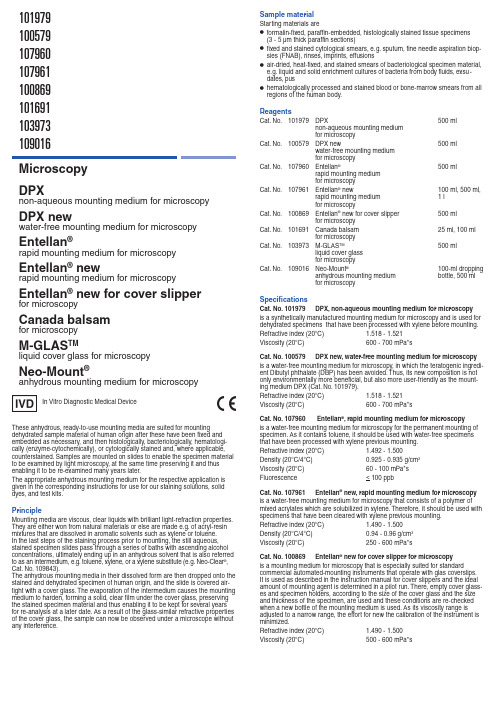
These anhydrous, ready-to-use mounting media are suited for mountingdehydrated sample material of human origin after these have been fi xed and embedded as necessary, and then histologically, bacteriologically, hematologi-cally (enzyme-cytochemically), or cytologically stained and, where applicable, counterstained. Samples are mounted on slides to enable the specimen material to be examined by light microscopy, at the same time preserving it and thus enabling it to be re-examined many years later.The appropriate anhydrous mounting medium for the respective application is given in the corresponding instructions for use for our staining solutions, solid dyes, and test kits.PrincipleMounting media are viscous, clear liquids with brilliant light-refraction properties. They are either won from natural materials or else are made e.g. of acryl-resin mixtures that are dissolved in aromatic solvents such as xylene or toluene.In the last steps of the staining process prior to mounting, the still aqueous, stained specimen slides pass through a series of baths with ascending alcohol concentrations, ultimately ending up in an anhydrous solvent that is also referred to as an intermedium, e.g. toluene, xylene, or a xylene substitute (e. g. Neo-Clear ®, Cat. No. 109843).The anhydrous mounting media in their dissolved form are then dropped onto the stained and dehydrated specimen of human origin, and the slide is covered air-tight with a cover glass. The evaporation of the intermedium causes the mounting medium to harden, forming a solid, clear fi lm under the cover glass, preserving the stained specimen material and thus enabling it to be kept for several years for re-analysis at a later date. As a result of the glass-similar refractive properties of the cover glass, the sample can now be observed under a microscope without any interference.Microscopy DPXnon-aqueous mounting medium for microscopyDPX newwater-free mounting medium for microscopyEntellan ®rapid mounting medium for microscopyEntellan ® newrapid mounting medium for microscopyEntellan ® new for cover slipper for microscopy Canada balsam for microscopyM-GLAS TMliquid cover glass for microscopyNeo-Mount ®anhydrous mounting medium for microscopy101979100579107960107961100869101691103973109016In Vitro Diagnostic Medical DeviceSample materialStarting materials are • formalin-fi xed, paraffi n-embedded, histologically stained tissue specimens (3 - 5 µm thick paraffi n sections) • fi xed and stained cytological smears, e. g. sputum, fi ne needle aspiration biop- sies (FNAB), rinses, imprints, effusions • air-dried, heat-fi xed, and stained smears of bacteriological specimen material, e. g. liquid and solid enrichment cultures of bacteria from body fl uids, exsu - dates, pus•hematologically processed and stained blood or bone-marrow smears from all regions of the human body.ReagentsCat. No. 101979 DPX 500 ml non-aqueous mounting medium for microscopy Cat. No. 100579 DPX new 500 ml water-free mounting medium for microscopyCat. No. 107960 Entellan ® 500 ml rapid mounting medium for microscopy Cat. No. 107961 Entellan ® new 100 ml, 500 ml, rapid mounting medium 1 l for microscopyCat. No. 100869 Entellan ® new for cover slipper 500 ml for microscopy Cat. No. 101691 Canada balsam 25 ml, 100 ml for microscopyCat. No. 103973 M-GLAS TM 500 ml liquid cover glass for microscopyCat. No. 109016 Neo-Mount ® 100-ml dropping anhydrous mounting medium bottle, 500 ml for microscopySpecifi cationsCat. No. 101979 DPX, non-aqueous mounting medium for microscopy is a synthetically manufactured mounting medium for microscopy and is used for dehydrated specimens that have been processed with xylene before mounting. Refractive index (20°C) 1.518 - 1.521Viscosity (20°C) 600 - 700 mPa*s Cat. No. 100579 DPX new, water-free mounting medium for microscopy is a water-free mounting medium for microscopy, in which the teratogenic ingredi-ent Dibutyl phthalate (DBP) has been avoided. Thus, its new composition is not only environmentally more benefi cial, but also more user-friendly as the mount-ing medium DPX (Cat. No. 101979).Refractive index (20°C) 1.518 - 1.521Viscosity (20°C) 600 - 700 mPa*s Cat. No. 107960 Entellan ®, rapid mounting medium for microscopyis a water-free mounting medium for microscopy for the permanent mounting of specimen. As it contains toluene, it should be used with water-free specimens that have been processed with xylene previous mounting.Refractive index (20°C) 1.492 - 1.500Density (20°C/4°C) 0.925 - 0.935 g/cm 3Viscosity (20°C) 60 - 100 mPa*sluorescence< 100 ppb Cat. No. 107961 Entellan ® new, rapid mounting medium for microscopyis a water-free mounting medium for microscopy that consists of a polymer of mixed acrylates which are solubilized in xylene. Therefore, it should be used with specimens that have been cleared with xylene previous mounting. Refractive index (20°C) 1.490 - 1.500Density (20°C/4°C) 0.94 - 0.96 g/cm 3Viscosity (20°C) 250 - 600 mPa*s Cat. No. 100869 Entellan ® new for cover slipper for microscopy is a mounting medium for microscopy that is especially suited for standardcommercial automated-mounting instruments that operate with glas coverslips. It is used as described in the instruction manual for cover slippers and the ideal amount of mounting agent is determined in a pilot run. There, empty cover glass-es and specimen holders, according to the size of the cover glass and the size and thickness of the specimen, are used and these conditions are re-checked when a new bottle of the mounting medium is used. As its viscosity range is adjusted to a narrow range, the effort for new the calibration of the instrument is minimized.Refractive index (20°C) 1.490 - 1.500Viscosity (20°C) 500 - 600 mPa*sResultThe use of these anhydrous, ready-to-use mounting media results in completelyairtight specimen slides, the structure and stain pattern of which remains pre-served over the long term, enabling them to be microscopically re-analyzed at a later date.Trouble-shootingOil-drop-shaped artefacts on the slide•When exchanging one anhydrous mounting medium in a cover slipper for another, e. g. when switching from DPX to DPX new, it is absolutely imperative to rinse the entire injection system of the cover slipper with the solvent xylene before using the new mounting medium. Only then can the new mounting medium be used.Turbidity of the slides•As a measure to ensure that the specimen slides retain optimal optical proper- ties and their transparency, in all cases a mounting medium must be used that is based on the solvent/intermediate used for the clarification process. The Neo-Mount ® mounting medium is, for example, not compatible with xylene and hence should be used only in combination with the intermediate Neo-Clear ®.No color stability over longer storage times• A minimum quality of the solvents must be observed.T echnical-grade solvents may have a relatively high water content, which may result in incomplete dehydration and hence in the stained specimen becoming turbid or decolorized.• A minimum quality and staining-dye content must be observed to ensure that the staining pattern of the specimens remains stable over the long term. Air bubbles and inclusions• In all cases a mounting medium must be used that is based on the solvent / intermediate used for the clarification process.• The volume of the mounting medium applied to the specimen must be care- fully monitored (to avoid too much or too little mounting medium).• The drying times for the specimens must be observed.The specimens must be completely dehydrated before microscopy with im- mersion oil, i. e. always allow the specimens to dry completely and mount thoroughly.•The evaporation of the solvent after mounting must be borne in mind, and specimen slides must be dried for at least 20 - 30 min.Technical notesThe microscope used should meet the requirements of a medical diagnostic laboratory.When using automated-mounting instruments, please follow the instructions for use supplied by the supplier of the system and software.Remove surplus immersion oil before fi ling.DiagnosticsDiagnoses are to be made only by authorized and trained personnel. Valid nomenclatures must be used.Further tests must be selected and implemented according to recognized methods.Suitable controls should be conducted with each application in order to avoid an incorrect result.StorageCat. Nos. 101979, 100579, 107960, 107961, 100869, 103973, 109016:Store the listed mounting media at +15 °C to +25 °C.Cat. No. 101691:Store the Canada balsam for microscopy at +5 °C to +30 °C.Shelf-lifeCat. Nos. 101979, 100579, 107960, 107961, 100869, 103973, 109016:The listed mounting media can be used until the stated expiry date.After fi rst opening of the bottle, the contents can be used up to the stated expiry date when stored at +15 °C to +25 °C.Cat. No. 101691:The Canada balsam for microscopy can be used until the stated expiry date.After opening the bottle the fi rst time and subsequent storage of the tightly re-closed bottle at +5°C to +30 °C, the medium can be used up to the printed expiry date.Additional instructionsFor professional use only.In order to avoid errors, the application must be carried out by qualifi ed personnel only.National guidelines for work safety and quality assurance must be followed.Microscopes equipped according to the standard must be used.Protection against infectionEffective measures must be taken to protect against infection in line with labora-tory guidelines.Cat. No. 101691 Canada balsam for microscopyis a commonly used mounting medium for microscopy to prepare permanent slides. It is produced from the resin of the balsam fi r tree and its use can be combined with xylene-containing specimens.Refractive index (20°C) 1.515 - 1.530Density (20°C/4°C) 0.980 g/cm 3Viscosity (20°C) 3000 mPa*s Cat. No. 103973 M-GLAS TM , liquid cover glass for microscopyis used in cytology instead of a cover glass to ensure that the stained specimens are homogenously covered. A few drops are applied onto the specimen, taking care that the mounting medium is evenly distributed over the specimen material. After the solvent has evaporated, a solid, protective lacquer fi lm remains that ensures that the specimen material is preserved.Refractive index (20°C) 1.490 - 1.500Density (20°C/4°C) 0.980 g/cm 3Viscosity (20°C) 500 - 600 mPa*sluorescence < 250 ppb Cat. No. 109016 Neo-Mount ®, anhydrous mounting medium for microscopyis an extremely color-stable mounting medium for microscopy, which is pro-duced with solvents based on mixtures of aliphatic hydrocarbons. It contains an aromatic-free substitute for xylene, thus, Neo-Mount ® needs to be combined with Neo-Clear ® (Cat. No. 109843) exclusively. Xylene must be avoided in the mount-ing step, as it will cause the slides to become cloudy and streaked. The applica-tion of Neo-Mount ® is not recommended in fl uorescence microscopy for clinical diagnostics. In addition, by placing the dehydrated slides on fi lter paper for ap-prox. 1 minute prior mounting, any excess of Neo-Clear ® could be circumvented, as air bubbles might arise under the coverslip. The same precondition should also be met when mounting specimens using cover-slip machines; in this area, Neo-Clear ® can be most effi ciently eliminated by incubation of the slides for one minute in an empty slide rack.Refractive index (20°C) 1.417 - 1.465Viscosity (20°C) 250 - 350 mPa*s Also required:Cat. No. 100974 Ethanol denatured with about 1 l, 2.5 l 1 % methyl ethyl ketone for analysis EMSURE ®Cat. No. 108297 Xylene (isomeric mixture) for analysis 2.5 l, 4 l EMSURE ® ACS,ISO,Reag. Ph Eur Cat. No. 109843 Neo-Clear ® (xylene substitute) 5 l, 25 lfor microscopySample preparationThe sampling must be performed by qualifi ed personnel.All samples must be treated using state-of-the-art technology.All samples must be clearly labeled.Suitable instruments must be used for taking samples and their preparation. Fol-low the manufacturer’s instructions for application / use.The specimen material is processed, stained (and counterstained where ap-plicable), and mounted according to the instructions for use of our staining solu-tions, solid dyes, and test kits.Histological and cytological specimens must be completely dehydrated before mounting. In the last stage, either xylene or a xylene substitute should be used to prevent the occurrence of turbidity due to aqueous solutions.Hematological and bacteriological specimens must be dries completely before microscopy using immersion oil, i. e. allow specimen slides to dry thoroughly or, if necessary, cover with a cover glass, otherwise the microscopic image will become turbid.Reagent preparationAll listed anhydrous mounting media are ready-to-use, dilution of the mounting media is not necessary.When exchanging one anhydrous mounting medium in a cover slipper foranother, e. g. when switching from DPX to DPX new, it is absolutely imperative to rinse the entire injection system of the cover slipper with the solvent xylene be-fore using the new mounting medium. Only then can the new mounting medium be used.If this is not done, oil-drop-shaped artefacts will form on the slide.ProcedureThe mounting medium must contain the same solvent, used for the water-clearing procedure to obtain the optimal optical properties and transparency of the slides.All mounting procedures should be carried out in a fume hood.The slides are mounted by dropping approx. 0.2 ml of the listed mounting me-dium onto the horizontal slide using a glass rod, which will fi ll the space between slide and cover glass. As soon as a homogeneous distribution of the solution is guaranteed, gently add a clean cover glass and avoid air bubbles. Allow this setup to dry and harden for about 20 - 30 min in a horizontal position.When pre-treated in the correct manner, the color of the specimens remains stable for at least fi ve years.The use of immersion oil is recommended for the analysis of stained slides with a microscopic magnifi cation >40x.Other IVD productsCat. No. 100496 Formaldehyde solution 4%, 350 ml and buffered, pH 6.9 (approx. 10% Formalin 700 ml (in bottle solution) with wide neck), for histology 5 l, 10 l,10 l Titripac ®Cat. No. 101646 P AS staining kit 2x 500 mlfor detection of aldehyde and mucosubstancesCat. No. 102480 Eosin-Phloxine solution, alcoholic 500 ml, 1 l for microscopyCat. No. 105174 Hematoxylin solution modifi ed acc. to Gill III 500 ml, 1 l, 2.5 l for microscopyCat. No. 109204 Giemsa’s azur eosin methylene blue 100 ml, 500 ml,solution 1 l, 2.5 l for microscopy Cat. No. 111609 Histosec ® pastilles 1 kg, 10 kg (4x soldifi cation point 56-58°C 2.5 kg), 25 kg embedding agent for histology Cat. No. 111885 Gram-color stain set 1 setfor the Gram staining methodCat. No. 115161 Histosec ® pastilles (without DMSO) 10 kg (4x 2.5 kg), soldifi cation point 56-58°C 25 kgembedding agent for histologyInstructions for disposalThe package must be disposed of in accordance with the current disposal guidelines.Used solutions and solutions that are past their shelf-life must be disposed of as special waste in accordance with local guidelines. Information on dis-posal can be obtained under the Quick Link “Hints for Disposal of Microscopy Products” at . Within the EU the currently applica-ble REGULATION (EC) No 1272/2008 on classification, labelling and packaging of substances and mixtures, amending and repealing. Directives 67/548/EEC and 1999/45/EC, and amending Regulation (EC) No 1907/2006 applies.Auxiliary reagentsCat. No. 100974 Ethanol denatured with about 1 l, 2.5 l1 % methyl ethyl ketone for analysis EMSURE ®Cat. No. 100983 Ethanol absolute for analysis EMSURE ® 1 l, 2.5 l, 5 l ACS, ISO, Reag. Ph Eur Cat. No. 104699 Immersion oil 100-ml droppingfor microscopy bottle, 100 ml,500 ml Cat. No. 108297 Xylene (isomeric mixture) for analysis 2.5 l, 4 l EMSURE ® ACS,ISO,Reag. Ph Eur Cat. No. 109843 Neo-Clear ® (xylene substitute) 5 l, 25 lfor microscopyHazard classifi cationCat. Nos. 101979, 100579, 107960, 107961, 100869, 101691, 103973, 109016Please observe the hazard classifi cation printed on the label and the information given in the safety data sheet.The safety data sheet is available on the website and on request.Main components of the productsCat. No. 101979CAS-No 9003-53-6 in 70 % (w/w) xylene Cat. No. 100579Copolymer in 70 % (w/w) xylene Cat. No. 107960Mixed acrylate in 75 % (w/w) toluene 1 l = 0.93 kgCat. No. 107961Polymer of mixed acrylates in 60 % (w/w) xylene 1 l = 0.95 kg Cat. No. 100869Polymer of mixed acrylates in 60 % (w/w) xylene 1 l = 0.95 kg Cat. No. 101691CAS-No 8007-47-41 l = 0.98 kgCat. No. 103973Polymer of mixed acrylates in 73.3 % (w/w) toluene 1 l = 0.91 kg Cat. No. 109016Polymer of mixed acrylates in 64 % (w/w) Shellsol 140/165Status: 2016-03-31Merck KGaA, 64271 Darmstadt, Germany T el. +49(0)6151 72-2440EMD Millipore Corporation, 290 Concord Road, Billerica,MA 01821, USA, Tel. +1-978-715-4321Consult instructions for useTemperature limitationUse byYYYY -MM-DD Caution, consultaccompanying documentsManufacturer Catalog number Batch code。
麦当劳马腊器操作手册说明书

Telephone: 818-3596
Distributed by:
H&K International 1343 South Henderson Avenue
Dallas, TX 75223 U.S.A.
Telephone: (214) 818-3500
Corrections of such defects by repair or replacement shall constitute fulfillment of all company obligations to the purchaser.
H&K shall not be liable for loss, damages, or expenses arising from the misuse, abuse, alteration, accident or improper installation of the Marinator such as:
This manual is for the exclusive use of licensees and employees of McDonald’s Systems Inc.
Page 2 of 13
Marinator Operations Manual
Warnings
STORE MANAGERS-
DO NOT OPERATE OR SERVICE THE MARINATOR WITHOUT FIRST READING THIS MANUAL.
USE CAUTION WHEN SETTING UP, OPERATING OR CLEANING THE MARINATOR TO AVOID CONTACT WITH HEATED SURFACES.
NeroHistory手册
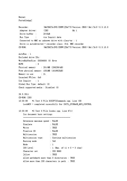
BernatPortableAppZRecorder: <MATSHITA DVD/CDRW UJDA775>Version: CB03 - HA 1 TA 0 - 8.3.13.0 Adapter driver: <IDE> HA 1Drive buffer : 2048kBBus Type : via Inquiry dataConnected to MMC as unknown drive with class-nr : 1Drive is autodetected - recorder class: Std. MMC recorderCD-ROM: <MATSHITA DVD/CDRW UJDA775>Version: CB03 - HA 1 TA 0 - 8.3.13.0AutoRun : 1Excluded drive IDs:WriteBufferSize: 83886080 (0) ByteBUFE : 0Physical memory : 2014MB (2062564kB)Free physical memory: 1581MB (1619928kB)Memory in use : 21Uncached PFiles: 0x0Use Inquiry : 1Global Bus Type: default (0)Check supported media : Disabled (0)26.5.2011CD-ROM (ISO)18:03:09 #1 Text 0 File SCSIPTICommands.cpp, Line 450LockMCN - completed sucessfully for IOCTL_STORAGE_MCN_CONTROL18:03:09 #2 Text 0 File Isodoc.cpp, Line 6714Iso document burn settings------------------------------------------Determine maximum speed : FALSESimulate : FALSEWrite : TRUEFinalize CD : FALSEMultisession : TRUEMultisession type: : Continue multisessionBurning mode : TAOMode : 1ISO Level : 1 (Max. of 11 = 8 + 3 char)Character set : ISO 9660Joliet : TRUEAllow pathdepth more than 8 directories : TRUEAllow more than 255 characters in path : TRUEWrite ISO9660 ;1 file extensions : TRUE18:03:09 #3 Text 0 File Burncd.cpp, Line 3309MATSHITA DVD/CDRW UJDA775防烧坏保护已激活18:03:10 #4 ISO9660GEN -11 File Geniso.cpp, Line 3349First writeable address = 0 (0x00000000)18:03:10 #5 ISO9660GEN -11 File Geniso.cpp, Line 3349First writeable address = 359844 (0x00057DA4)18:03:10 #6 Text 0 File ThreadedTransferInterface.cpp, Line 1027 Removed 2 run-out blocks from end of track 0. Length: 600 -> 598.18:03:10 #7 Text 0 File Burncd.cpp, Line 3639Turn on Track-At-Once, using CD-R/RW media18:03:10 #8 Text 0 File ThreadedTransferInterface.cpp, Line 1027 Removed 2 run-out blocks from end of track 6. Length: 600 -> 598.18:03:15 #9 Text 0 File FilesystemSettingsValidator.cpp, Line 142 FS Settings: using validator 'CUDFSettingsValidatorCD'ParamMode = 'automatic', changing UDF partition type from 'physical' to 'physical'Changing UDF revision from '1.02' to '1.02'18:03:15 #10 Text 0 File ThreadedTransferInterface.cpp, Line 1027 Removed 2 run-out blocks from end of track 6. Length: 600 -> 598.18:03:15 #11 Phase 41 File dlgbrnst.cpp, Line 1767Compilation will not fit onto a blank disc18:03:18 #12 Text 0 File DlgWaitCD.cpp, Line 311很遗憾,您的多区段光盘已满。
mce遥控助手使用方法收藏
mce遥控助手使用方法收藏mce 遥控助手使用方法收藏最近搞了套htpc,遥控器+接收器是用的惠普的全套,用了下遥控器发现部分按键无法使用,看来只能是找个软件定义一下按键了。
网上搜了一大通,终于找到一款的软件:lm remote keymap 可以自定义遥控器的各个按键,还是先介绍一下这个软件吧。
优点:功能强大,使用方便,通用(rc6标准遥控器都支持)缺点:没有帮助文档网上搜了下,也没找到帮助类似的文档,只能自己摸索着找找使用方法了。
现在把摸索的结果同大家分享一下。
呵呵软件安装完毕后,打开,弹出窗口中共有5栏内容,依次如下:遥控器配置文件----------是负责修改配置文件的,选择遥控器和设置遥控器两个选项中的内容可以不用改动ir devices---------应该是选择遥控设备了,这个也可以保持默认音量osd外观-----是调节音量时显示的显示的进度条外观按钮osd外观-----可以保持默认菜单osd外观-----可以保持默认下面我们所做的,就是修改遥控器的配置文件,在下拉列表框中我们可以看到有“键盘模式”等多个配置文件,这个是已经配置好的按键定义文件,“+”号表示新建配置文件,“-”号表示删除列表框中选定的配置文件,“编辑”自然就是编辑选定的配置文件了。
下面我们以“键盘模式”为例,说明我们如何自己定义遥控器按键。
首先在列表框中选定“键盘模式”,然后点击右侧的“编辑”按钮,会弹出编辑遥控器按键的对话框。
对话框左侧对应的是真实遥控器上的按键,中间是左侧图中各个按键的功能列表(即遥控器上的每个按键都是列表中的一项,项的名字就是遥控器按键的名字,不过遥控器按键上部分是使用的符号表示),右侧是当前编辑的配置文件说明和按键的动作定义。
下面详细说明一下左中右三个部分。
首先,是左边的遥控器图片。
用鼠标点击图片上遥控器的每个按键,当前选定的按键会变绿,中间部分该按键对应的项也会自动选中(按键定义也自动展开)。
- 1、下载文档前请自行甄别文档内容的完整性,平台不提供额外的编辑、内容补充、找答案等附加服务。
- 2、"仅部分预览"的文档,不可在线预览部分如存在完整性等问题,可反馈申请退款(可完整预览的文档不适用该条件!)。
- 3、如文档侵犯您的权益,请联系客服反馈,我们会尽快为您处理(人工客服工作时间:9:00-18:30)。
Nero MediaStreaming for MCE 使用手冊Nero AG版權及商標資訊本手冊及其所有內容受著作權保護,且為 Nero AG 之財產。
保留所有權利。
本手冊所包含的內容受國際著作權法的保護。
未經 Nero AG 明確的書面許可,不得重製、傳送、或複製本手冊中的任何部分。
所有商標名稱及商標均為其各別擁有者之財產。
Nero AG 拒絕任何超出合法保證協議的賠償要求。
對於手冊內容之正確性,Nero AG 不負任何責任。
所附軟體之內容或手冊之內容如有變更,恕不預先通知。
此處所列出的商標僅做為資訊用途。
版權所有© 2007 Nero AG 及其授權者。
保留所有權利。
REV 2目錄第 3 頁目錄1 一般資訊 4 1.1 手冊慣例4 1.2 關於 Nero MediaStreaming - MCE 外掛程式 4 2 技術資訊5 2.1 MCE PC 的系統需求 5 2.1.1 作業系統 5 2.1.2 顯示器設定 5 2.1.3 音效設定 5 2.1.4 DirectX 5 2.1.5 媒體伺服器 5 2.1.6 瀏覽器5 3 安裝 Nero MediaStreaming6 4 Windows® Media Center 中的 Nero MediaStreaming7 4.1 啟動 Nero MediaStreaming 7 5 Nero MediaStreaming 啟動畫面 9 6 [電視頻道] 畫面 10 7 [音樂] 畫面 118 [影片] 畫面 129 [集合] 畫面 13 10 [相片] 畫面 14 11 索引 15 12聯絡資訊16第 4 頁1.1 手冊慣例為了讓手冊發揮最大的功效,請注意下列慣例:符號意義表示警告、必須嚴格遵守的指定條件或指示。
表示其他資訊或建議。
1. 啟動 …行首之編號表示要求執行某個動作。
請依照指定的順序執行這些動作。
Æ 表示中間的結果。
Î表示結果。
確定 表示程式介面中所出現的文字段落或按鈕。
以粗體表示。
章節 表示參照其他章節。
章節會以連結之形式執行並以紅色加底線表示。
[…]表示輸入命令的鍵盤捷徑。
1.2 關於 Nero MediaStreaming - MCE 外掛程式利用 Nero MediaStreaming,您可以在區域 (無線) 網路上,使用 Windows® XP Media Cen-ter Edition (MCE) 的 MCE 介面將集合中的音樂和影片檔案以及目前正在播放的電視節目,在不同的電腦之間即時傳送。
在這個過程中,Nero MediaHome 可以做為媒體伺服器,而用戶端的電腦上只須要有 Nero MediaStreaming 外掛程式即可。
如此一來,您就可以從連接至電視盒的 MCE 電腦存取另一台電腦上的媒體檔案,並擷取存放在該處電腦上的影片。
如果將 Xbox 連接至電視盒,您也可以利用此功能來連接至含有媒體檔案的遠端 MCE 電腦,將影片顯示在電視螢幕上。
如果將 MCE 電腦連接至電視連接器,您也可以存取遠端 MCE 電腦上的影片集合,或是從其他 MCE 用戶端 (例如筆記型電腦) 存取目前的電視節目。
第 5 頁2.1 MCE PC 的系統需求2.1.1 作業系統Windows Vista™ Media CenterWindows ® XP Media Center Edition 2005 Rollup 2Windows® Media Center Edition 2005 之後的版本,必須從網路更新 Nero MediaStrea-ming,請於所指定之日期至 下載。
請注意,任何 Windows ® XP Media Center Edition 2005 的自動更新均不包含 Media Cen-ter Edition Rollup 2。
您可能必須另行下載並安裝。
2.1.1.1 處理器至少 1.6 GHz 或同等級處理器, 256 MB RAM2.1.2 顯示器設定顯示卡需支援重疊顯示,最低配備為 8MB 影像記憶體、800x600 像素解析度,和 16 位元彩色設定。
但建議使用 24 位元或 32 位元全彩設定。
建議安裝最新版且經 WHQL 認證之裝置驅動程式。
2.1.3 音效設定相容於 16 位元 Microsoft® Windows® 的音效卡及喇叭。
建議安裝最新版且經 WHQL 認證之裝置驅動程式。
2.1.4 DirectXMicrosoft® DirectX 9.0 (含) 以上版本。
2.1.5 媒體伺服器區域網路中至少有一台電腦安裝 Nero MediaHome 伺服器。
2.1.6 瀏覽器Microsoft ® Internet Explorer 5.0 (含) 以上版本。
安裝Nero MediaStreaming第 6 頁3 安裝 Nero MediaStreaming安裝 Nero 7 時,如果電腦上已安裝 Windows Vista™ Media Center 或 Windows® XP Media Center Edition 2005 Rollup 2 (或更新版本),則會同時自動安裝 Nero MediaStreaming MCE 外掛程式。
如果是自訂安裝,您可以選擇不安裝 Nero MediaStreaming。
在此情況下,您可以在稍後利用 Nero ProductSetup 來安裝 Nero MediaStreaming。
要 安裝 Nero MediaStreaming,請執行下列步驟:1. 關閉所有非必要的 Windows® 應用程式,並關閉所有正在執行的防毒軟體。
2. 開啟 Nero StartSmart。
3. 在 Nero StartSmart 延伸區域中選取 [Nero Toolkit] > [Nero ProductSetup]。
Æ 會出現 Nero ProductSetup 畫面。
4. 選取 [設定] 功能表圖示。
5. 按一下 [變更] 按鈕。
Æ 會顯示 Nero 7 安裝精靈的初始畫面 – 自訂安裝。
6. 按一下 [特殊應用程式] 項目前方的 [+] 圖示。
7. 會開啟 [特殊應用程式] 項目。
8. 在 Nero 應用程式清單中的 [Nero MediaStreaming 外掛程式] 項目上按一下。
Æ 開啟快顯功能表。
9. 選擇 [此功能],所有子功能將會安裝在本機硬碟上。
Æ 該選項現在已不再是紅色 X,而是如其他反白選取的應用程式一樣,以磁碟機圖示表示。
10. 按一下 [下一步] 按鈕。
Æ 會顯示「安裝 Nero 7」畫面,並且持續告知您安裝程序的進度。
接著會自動出現 [設定]畫面。
11. 按一下 [下一步] 按鈕。
Æ 出現對話方塊,告知您必須重新啟動 Windows®。
12. 按一下 [是] 按鈕。
Î 電腦會重新啟動。
Nero MediaStreaming 已安裝完成,並再次顯示 Nero StartSmart。
第 7 頁4 Windows® Media Center 中的 Nero MediaStreaming在 MCE 電腦上,當 Nero 套件安裝完成後,就會自動在 [其他程式] 選單內顯示 Nero Media-Streaming 外掛程式。
本節將說明如何利用電腦鍵盤及滑鼠來控制 Nero MediaStreaming。
如果是使用遙控器來操作 Windows Media Center,請參閱遙控器的操作指示及程式中的指示。
4.1 啟動 Nero MediaStreaming要開始使用 Nero MediaStreaming,必須滿足下列條件:必須在網路中至少一台電腦上安裝 Nero MediaHome。
必須啟動 Nero MediaHome 伺服器。
MediaHome 伺服器上含有所需媒體檔案的磁碟機和資料夾必須為已分享。
關於使用 Nero MediaHome 的詳細資訊,請參考相關使用手冊,手冊的 PDF 檔可於 取得。
要啟動 Nero MediaStreaming,請執行下列步驟:1. 啟動 Microsoft® Windows Media Center Edition。
Æ 會出現 Media Center 的啟動畫面。
2. 如果您使用的是 Windows® XP,請按一下 [更多程式] 按鈕。
Æ 會顯示 [Nero MediaStreaming] 功能表圖示。
3. 如果您使用的是 Windows Vista™:1. 按一下 [線上媒體] 按鈕。
2. 按一下 [程式] 按鈕。
Æ 會顯示 [程式庫]。
3. 按一下 [Nero 外掛程式] 按鈕。
Æ 會顯示 [Nero MediaStreaming] 功能表圖示。
如果您使用的是 Windows Vista™,則 [Nero 外掛程式] 按鈕通常會出現在起始畫面中。
但是,如果您有安裝額外的 MCE 外掛程式,則可能會隱藏該按鈕。
第 8 頁4. 按一下 [Nero MediaStreaming] 功能表圖示。
Æ 會出現 [Nero MediaStreaming] 畫面,開始搜尋 Nero MediaHome 伺服器並顯示所找到的伺服器。
5. 在所需的伺服器上按兩下。
Î 會顯示 [Nero MediaHome] 畫面,提供所選 Nero MediaHome 伺服器上所有媒體類型的按鈕。
Nero MediaStreaming 啟動畫面第 9 頁5 Nero MediaStreaming 啟動畫面[Nero MediaHome] 畫面中包含下列輸入選項:功能表圖示 電視頻道開啟 [電視頻道] 畫面,顯示可以觀看的電視頻道供您選擇 (請參閱〈[電視頻道] 畫面〉)。
音樂開啟 [音樂] 畫面,您可以在此選擇要播放的音樂 (請參閱〈[音樂] 畫面〉)。
影片開啟 [影片] 畫面,您可以在此選擇要播放的影片 (請參閱〈[影片] 畫面〉)。
集合開啟 [集合] 畫面,您可以在此選擇要播放的媒體集合 (請參閱〈[集合] 畫面〉)。
相片 開啟 [相片] 畫面,您可以在此選擇要播放的相片 (請參閱〈[相片] 畫面〉)。
按鈕 方向鍵 上下瀏覽畫面上的功能表圖示。
左側的數字代表眾多按鈕中剛選擇的按鈕。
用來播放各種媒體的 Windows® XP Media Center 控制列會顯示在畫面下方。