ACT-F1M32T-080F14I中文资料
横河PLC-FA-M3概述
FA-M3 主单元
顺控 CPU 模块
光纤 FA-总线 2 模块
电源 模块
顺控 CPU (最多3个槽位)) 辅助单元 1
系统配置
上级通信
- 通过以太网与工作站或个人电脑连接
工作站或个人电脑
以太网 FA-M3
- 通过个人电脑链接模块与图形显示控制面板连接
工作站或个人电脑
FA-M3
调制解调器模块
公共电话线
外形尺寸٠FA-M3 符合的标准......................................................................................................39
Yokogawa Electric Corporation
GS 34M6A01-01C © 版权所有 2006 年 1 月
通用技术规格٠电源规格........................................................................................ 5 性能规格 ................................................................................................................. 6 FA-M3 Value /FA-M3 Value II 的顺控 CPU 模块性能规格 ...........................9, 10 梯形图顺序基本指令/ ...........................................................................................11 梯形图顺序应用指令.............................................................................................12
施耐德产品型号说明

NS630N NS630N NS630H NS630N NS630N NS630H NS630N NS630H NS630H NS630N NS630H NS630L NS630N NS630L NS630L NS630H NS630L NS630L NS630H NS630L NS630L NS630L
NS630N NS630N NS630N
施耐德电气公司宣传培训部-施耐德介绍- 06/2000
2
变压器与断路器配合选用推荐表(续)
变压器容量 并联数量 N*KVA 变压器 额定电流 In(A) 变压器 短路电 压 Ucc% 4 4 4 6 6 6 6 6 6 6 6 6 6 6 6 6 6 6 6 6 6 6 进线 短路电流 KA 进线断路器 最小分断能力 KA 进线断路 器型号 出线 短路电流 KA 出线断路器 型号 〈 =100A NS100N NS100H NS100H NS100N NS100H NS100H NS100N NS100H NS630H NS100H NS100H NS100L NS100H NS100L NS100L NS100H NS100L NS100L NS100H NS100L NS100L NS100L 160A 250A 400A 630A
Lcs=75%Lcu;
框架电流 08:800A 10:1000A 12:1250A 16:1600A 20:2000A
可由客户自已加装的附件: 辅助开关(OF)选件 门框(CDP) 瞬动欠压脱扣器(MN)
说明:
断路器的额定值与框架电流等级相同 MCH,MX/XF电压等级有AC200V及AC380V两种选择 (MX与XF必须选择相同的电压等级)
12
Masterpact D 空气断路器选型表 MD16-2
CTU样本

CTU空气断路器和负荷开关产品目录施耐德电气善用其效尽享其能全球能效管理专家施耐德电气为世界100多个国家提供整体解决方案,其中在能源与基础设施、工业过程控制、楼宇自动化和数据中心与网络等市场处于世界领先地位,在住宅应用领域也拥有强大的市场能力。
致力于为客户提供安全、可靠、高效的能源,施耐德电气2011年的销售额为224亿欧元,拥有超过130,000名员工。
施耐德电气助您——善用其效,尽享其能!施耐德电气在中国1987年,施耐德电气在天津成立第一家合资工厂梅兰日兰,将断路器技术带到中国,取代传统保险丝,使得中国用户用电安全性大为增强,并为断路器标准的建立作出了卓越的贡献。
90年代初,施耐德电气旗下品牌奇胜率先将开关面板带入中国,结束了中国使用灯绳开关的时代。
施耐德电气的高额投资有力地支持了中国的经济建设,并为中国客户提供了先进的产品支持和完善的技术服务,中低压电器、变频器、接触器等工业产品大量运用在中国国内的经济建设中,促进了中国工业化的进程。
目前,施耐德电气在中国共建立了53个办事处,28家工厂,7个物流中心,1个研修学院,3个研发中心,1个实验室,700多家分销商和遍布全国的销售网络。
施耐德电气中国目前员工数近28,000人。
通过与合作伙伴以及大量经销商的合作,施耐德电气为中国创造了成千上万个就业机会。
施耐德电气能效管理平台凭借其对五大市场的深刻了解、对集团客户的悉心关爱,以及在能效管理领域的丰富经验,施耐德电气从一个优秀的产品和设备供应商逐步成长为整体解决方案提供商。
今年,施耐德电气首次集成其在建筑楼宇、IT、安防、电力及工业过程和设备等五大领域的专业技术和经验,将其高质量的产品和解决方案融合在一个统一的架构下,通过标准的界面为各行业客户提供一个开放、透明、节能、高效的能效管理平台,为企业客户节省高达30%的投资成本和运营成本。
转变p为了更好的改变带给电力生活前所未有的高效无忧目录概述 (6)功能和特性 (12)推荐安装方式 (35)尺寸和连接 (46)电路图 (61)附加特性 (66)选型指南 (68)相关产品简介 (81)随着我国供电系统的发展,从住宅小区配电间、箱式变电站,到输变电站和城农网改造,现代配电网络正发生着变化:供电网络规模不断扩大;配电系统保护日益复杂;供电可靠性、连续性要求不断提高;电力管理难度更大;用户的需求不断从电力供给转向电力服务……CTU系列低压断路器,为输配电系统量身定做,全面满足上述供电系统需求:●秉承施耐德电气一贯出色品质,经典的高可靠、免维护、高环境适应性设计!●零飞弧、完善锁定、双重绝缘、人性化操作,提供最高等级的安全!●经典的保护功能和基础的测量功能,实现最简约的选择!CTU系列低压断路器基于供配电客户需求进行全新设计,引领先进供电系统应用理念:●两进线一母联自动投切系统,实现低压系统智能切换!●独特合环控制功能,避免线路切换产生停电或晃电!●全新环保设计,贯穿产品寿命每一阶段!转变,为更可靠、更高效、更智能的配电网络应用而改变,我们为现在和将来而设想:现代供配电网络——能否通过优化电网管理,使系统运行维护更加便捷、高效;能否通过完备应用,带给用户更多价值、服务!高标准的环境适应性CTU系列低压断路器所具备的高环境适应能力,可以保障配电系统在剧烈环Array境变化或严酷环境条件下依然稳定运行,例如建筑领域常用的箱式变电站,无空调环境的地下配电室,或空间狭小的安装环境。
A-T CONTROLS INC Fitting Series FFTM3 FFTM3C 商品说明书
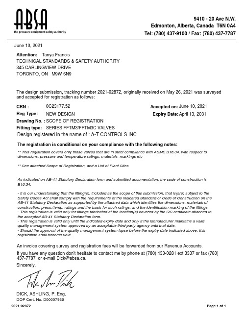
9410 - 20 Ave N.W.Edmonton, Alberta, Canada T6N 0A4Tel: (780) 437-9100 / Fax: (780) 437-7787June 10, 2021SERIES FFTM3/FFTM3C VALVESTORONTO, ON M9W 6N9345 CARLINGVIEW DRIVE CRN :Drawing No. :Accepted on:0C23177.52Reg Type:NEW DESIGNApril 13, 2031June 10, 2021Design registered in the name of : A-T CONTROLS INCExpiry Date:SCOPE OF REGISTRATION Fitting type:Attention:The design submission, tracking number 2021-02872, originally received on May 26, 2021 was surveyed and accepted for registration as follows:Sincerely,DICK, ASHLING, P. Eng.TECHNICAL STANDARDS & SAFETY AUTHORITY Tanya FrancisIf you have any question don't hesitate to contact me by phone at (780) 433-0281 ext 3337 or fax (780)****************************.The registration is conditional on your compliance with the following notes:** This registration covers only those valves that are in strict compliance with ASME B16.34, with respect to dimensions, pressure and temperature ratings, materials, markings etc ** See attached Scope of Registration, and a List of Plant SitesAs indicated on AB-41 Statutory Declaration form and submitted documentation, the code of construction is B16.34.- It is our understanding that the fitting(s), included as the scope of this submission, that is(are) subject to the Safety Codes Act shall comply with the requirements of the indicated Standard or Code of Construction on the AB-41 Statutory Declaration as supported by the attached data which identifies the dimensions, materials of construction, press./temp. ratings and the basis for such ratings, and the identification marking of the fittings.- This registration is valid only for fittings fabricated at the location(s) covered by the QC certificate attached to the accepted AB-41 Statutory Declaration form.- This registration is valid only until the indicated expiry date and only if the Manufacturer maintains a valid quality management system approved by an acceptable third-party agency until that date.- Should the approval of the quality management system lapse before the expiry date indicated above, this registration shall become void.DOP Cert. No. D0*******An invoice covering survey and registration fees will be forwarded from our Revenue Accounts.Page 1 of 12021-02872**** Ball Valves Series FFTM3/FFTM3C Class 150, 300 & 600** See attached Scope of Registration and List of Plant SitesABSASAFETY CODES ACT - PROVINCE OF ALBERTASee acceptance letter for conditions of registration.ASHLING DICK, P . Eng.2021-06-10Date:By:This stamp and signature have been affixed electronically to this registered design as required by Section 20(1) of the Pressure Equipment Safety Regulation, in accordance with the Electronic Transactions Act.2021-02872ACCEPTED:0C23177.520C23177.5Technical Standards and Safety Authority Boilers and Pressure Vessels SafetyProgramTHIS IS PART OF CRNABSASAFETY CODES ACT - PROVINCE OF ALBERTASee acceptance letter for conditions of registration.ASHLING DICK, P . Eng.2021-06-10Date:By:This stamp and signature have been affixed electronically to this registered design as required by Section 20(1) of the Pressure Equipment Safety Regulation, in accordance with the Electronic Transactions Act.2021-02872ACCEPTED:0C23177.520C23177.5Technical Standards and Safety Authority Boilers and Pressure Vessels SafetyProgramTHIS IS PART OF CRNBody Materials: ASTM A216 WCB & A351 CF8MABSASAFETY CODES ACT - PROVINCE OF ALBERTASee acceptance letter for conditions of registration.ASHLING DICK, P . Eng.2021-06-10Date:By:This stamp and signature have been affixed electronically to this registered design as required by Section 20(1) of the Pressure Equipment Safety Regulation, in accordance with the Electronic Transactions Act.2021-02872ACCEPTED:0C23177.520C23177.5Technical Standards and Safety Authority Boilers and Pressure Vessels SafetyProgramTHIS IS PART OF CRNABSASAFETY CODES ACT - PROVINCE OF ALBERTASee acceptance letter for conditions of registration.ASHLING DICK, P . Eng.2021-06-10Date:By:This stamp and signature have been affixed electronically to this registered design as required by Section 20(1) of the Pressure Equipment Safety Regulation, in accordance with the Electronic Transactions Act.2021-02872ACCEPTED:0C23177.52April 13, 2021A-T CONTROLS INC9955 INTERNATIONAL BLVDCINCINNATI OH 45246USWorkorder Type: Registration - Fitting(Conventional)Workorder No: 8005180Your Reference No.:Registered to: A-T CONTROLS INCDear PETE VEZEY,Technical Standards and Safety Authority (TSSA) is pleased to inform you that your submission has been reviewed and registered as follows:CRN : 0C23177.5Main Design No.: Ball Valves Series FFTM3/FFTM3C Class 150, 300 & 600 - See Scope of Registration & List of Plant SitesExpiry Date: Apr 13, 2031Please be advised that a valid quality control system must be maintained for the fitting registration to remain valid until the expiry date.The stamped copy of the approved registration and the invoice are mailed separately (There will be no hard copies for electronic submissions). Should you have any questions or require further assistance, please contact a CustomerServiceAdvisorat1.877.682.TSSA(8772)*********************************.Wewillbehappyto assist you. When contacting TSSA regarding this file, please refer to the Service Request number provided above.Yours truly,Wendy DuEngineer, BPVTel. : +1 416-734-3566Email:************Date:C.R.N.:April 13, 2021.0C23177.5Technical Standards and Safety AuthorityBoilers andPressure Vessels Safety ProgramREGISTEREDSigned:- See stamped Scope of Registration & List of Plant SitesApril 13, 20310C23177.5Technical Standards and Safety Authority Boilers and Pressure Vessels SafetyProgramTHIS IS PART OF CRNBody Materials: ASTM A216 WCB & A351 CF8MTHIS IS PART OF CRN 0C23177.5Technical Standards and Safety Authority Boilers and Pressure Vessels SafetyProgramDate:Account #:Journal #:35231June 18, 202178138TECHNICAL STANDARDS & SAFETY AUTHORITY 345 CARLINGVIEW DRIVE TORONTO ON M9W 6N9TSSAApplication for Design RegistrationThe design, as detailed in your, 0C23177.5 - A-T CONTROLS INC, for a Fitting is accepted for registration as follows:A-T CONTROLS, INC.CRN:0C23177.51Registered To:Drawing #:Scope of Registration Drawing Revision:N/ARe:Attn:Reviewer's Notes:Scope of Registration: Ball Valves Series FFTM3/FFTM3C Class 150, 300 & 600 - See Scope of Registration &List of Plant SitesAs required by CSA B51 4.2.1, this registration expires on 13-Apr-2031. This CRN is valid until the expiry date as long as the Manufacturer maintains a valid quality control program verified by an acceptable third-party agency until that date. Should the certification of the quality control program lapse before the expiry date, this registration shall become void. Any additional conditions of registration stated in TSSA CRN# 0C23177.5 registration shall apply to BC registration.This design was registered based on a technical review performed by the province of initial registration in accordance with the Association of Chief Inspectors policy on reciprocal recognition of design review.Contact me if you have any questions. The invoice for registration will be forwarded under separate :Emilia Tam*******************************Design AdministrationInspection and Technical ServicesMunicipal Relations508-401York AveWinnipeg, Manitoba Canada R3C 0P8T 204-945-3373 F 204-948-2089.mb.ca/itsm_main14 June 2021TSSA345 Carlingview DriveToronto, ON M9W 6N9Dear Tanya FrancisRe: Reciprocal CRN Registration in ManitobaYour application indicates that a CRN has been received in another Canadian Jurisdiction, and therefore your CRN has been registered in Manitoba as follows:File Number: 74-R1571CRN: 0C23177.54Scope: SOR: Ball Valve Series FFTM3 / FFTM3C Class 150, 300 & 600 and List of Plant Sites Manufacturer: A-T Controls IncExpiry Date: 13 April 2031Please find attached invoice for registration.As indicated by the Regulatory Reconciliation and Cooperation Table and the Reconciliation Agreement for the Canadian Registration Number (CRN) for Pressure Equipment, a CRN issued in any Canadian Jurisdiction will be accepted for use in Manitoba.In accordance with Steam and Pressure Plants Regulation and CSA B51, it is the manufacturer’s responsibility to file a Manufacturers Data Report, including partial data reports, with our office, prior to shipping pressure equipment to Manitoba.Please contact ****************.ca for any questions or concerns.Inspection and Technical ServicesMunicipal Relations508 - 401 York Avenue, Winnipeg Manitoba R3C 0P8T (204) 945-3373 | F (204) 948-2089。
MEMORY存储芯片MT29F32G08CBADAWP中文规格书

Electrical Specifications – AC Characteristics and Operating Conditions AC Characteristics: Command, Data, and Address Input (3.3V)Notes: 1.Operating mode timings meet ONFI timing mode 5 parameters.2.Timing for t ADL begins in the address cycle, on the final rising edge of WE#, and endswith the first rising edge of WE# for data input.AC Characteristics: Command, Data, and Address Input (1.8V) Note 1Notes: 1.Operating mode timings meet ONFI timing mode 4 parameters.2.Timing for t ADL begins in the address cycle on the final rising edge of WE#, and endswith the first rising edge of WE# for data input.4Gb, 8Gb, 16Gb: x8, x16 NAND Flash Memory Electrical Specifications – AC Characteristics and Operating ConditionsElectrical Specifications – DC Characteristics and Operating Conditions DC Characteristics and Operating Conditions (3.3V)Notes: 1.Measurement is taken with 1ms averaging intervals and begins after V CC reachesV CC(MIN).2.I OL (R/B#) may need to be relaxed if R/B pull-down strength is not set to full.3.V OH and V OL may need to be relaxed if I/O drive strength is not set to full.DC Characteristics and Operating Conditions (1.8V)Notes: 1.Typical and maximum values are for single-plane operation only. If device supports dual-plane operation, values are 20mA (TYP) and 40mA (MAX).2.Values are for single-die operations. Values could be higher for interleaved-die opera-tions.3.Measurement is taken with 1ms averaging intervals and begins after V CC reachesV CC(MIN).4.Test conditions for V OH and V OL.5.DC characteristics may need to be relaxed if R/B# pull-down strength is not set to full.。
电子保护断路器系列CT F-Frame 产品说明说明书

The Series C T F-Frame is equipped with the 210+ electronic trip unit and features LSI and LI protection settings. The F-Frame breaker is NEMA T, UL T and CSA T listed.Design flexibility• Three frames cover ampere range from 40 A to 225 A, reducing stock requirements and providing more flexibility than thermal-magnetic breakers• Each trip unit includes seven ampere ratingsand 10 protection profiles• Two protection types, LI and LSI, offer options for adjust-ability and coordination of systemsDesign savings• Uses accessories available on current F-Frame breaker• Same physical dimensions and terminal locations as thermal- magnetic and 310+ electronic F-Frame breakers• Available for aftermarket replacement of any F-Frame when electronic trip units are preferred• Reduced cost from F-Frame 310+ offering of electronic trip unit• Three trip units cover ampere range from 40 A to 225 A, reducing in-house stock and offering more flexibility Easy-to-use 210+ trip unit• Two simple rotary dials adjust settings for amperage and protection levels• Status indication LED notifies the user of operational statusA full range of accessories• In addition to using the same internal accessories as the standard F-Frame, the FDE with 210+ offers various handle locks, plug-in adapters and handle mechanisms• Includes same shunt tripand undervoltage release accessory options as other FD breakers, and the same left-hand side auxiliary and bell alarm contact options • A special 1A/1B auxiliary contact can be installed on the right-hand side; this contact must be factory installed• Uses a functional test kit in common with the 310+ and ACB Digitrip E (MTST230V); a new cable is included in the test kit to test 210+ trip unitsSeries C F-Frame molded-case circuitbreaker with 210+ electronic trip unitFDE 210+ trip unit features• No rating plug required •Factory-installed only; non-interchangeable •Available with LI or LSI protection profiles •Three frames with wide ampere ranges: 40–100 A, 70–150 A and 100–225 A •Fixed long time delay (10 sec at 6 x I r )• Thermal memory •Sealable clear cover to comply with UL and CSA requirements•Optional wire seal for cover (Cat. No. 5108A03H01)•Adjustable short-time delay pickup (LSI): 2–10 x I r•Multiple SD time delayoptions (LSI): INST , 150 ms, 300 ms and I 2t response •Adjustable Instantaneous pickup (LI): 2–12 x I n • Status indicator LED • Push-to-trip button •Optional self-powered plug-in test kit(Cat. No. MTST230V)FDE 210+ ordering guidelinesAvailable featuresA Internal accessories are listed with Underwriters Laboratories (UL) for factory installation. They arenot listed with UL for field installation. Any one internal accessory may be mounted in the left pole. Only a specially built 1A/1B auxiliary switch may be factory mounted in the right pole.FDE, HFDE and FDCE ratings and ampere rangesSpecification Description Breaker typeFDEHFDEFDCE AShort-circuit current ratings (kA rms) AC 50–60 Hz NEMA UL 489240 Vac 65100200480 Vac 3565100600 Vac 182525Number of poles 333Adjustable Long-time pickup CSA 22.2 No. 5225 A A = 100, B = 110, C = 125, D = 150, E = 175, F = 200,G = 225150 A B A = 70, B = 80, C = 90,D = 100,E = 110,F = 125,G = 150100 A A = 40, B = 50, C = 60,D = 70,E = 80,F = 90,G = 100Protection types LI, LSI Dimensions in inches (mm)H W DThree-pole 6.00 (152.4) 4.13 (104.9) 3.38 (85.9)Weight (approximate) lbs (kg) 4.5 (2.0) 4.5 (2.0)4.5 (2.0)A Contact Eaton for availability.B 150 A frame only available in protection style LI.ReferencesDocumentPublication numberTechnical data TD01203013E FAQ MZ01203001ELI trip unit controls LI protection settingsA A S position on 225 A frame set to breakeroverride value of 2400 A.LSI trip unit controlsLSI protection settingsTo learn more, visit /210plusEaton is a registered trademark.All other trademarks are property of their respective owners.Eaton1000 Eaton Boulevard Cleveland, OH 44122United States © 2015 EatonAll Rights Reserved Printed in USAPublication No. PA012010EN / Z16957September 2015Follow us on social media to get the latest product and support information.。
A-T Controls F8R Series 三件件球阀说明书

F8RM-20151006Copyright 2013 A-T Controls, Inc.Triac F8R Series Firesafe 3-piece ball valves are the finest quality 3-piece valves on the market. The high quality investment castings feature a fully machined bore. The superior live-loaded packing system is accomplished with Belleville washers, Grafoil packing and a unique primary pyramidal stem seal. This advanced sealing system provides protection against stem leaks experienced by ordinary ball valves.Easy to Automate!See automated data sheets for pre-sized assembliesPneumaticElectricCincinnati, Ohio FAX (513) 247-5462********************Lock Saddle Belleville WasherGlandGrafoil Packing Pyramidal (45°)Stem & Stem SealRTFE seats are standard, but various options are available for seat materials. The 50/50 STFE seat option is excellent for services that call for highertemperatures and more difficult applications including steam. Call us for details.C E R T I F I E DSERIES F 8R 3-Piece Firesafe*1/4” THRU 2” - 4 PCS.* 2-1/2”- 6 PCS.9955 International Blvd.Cincinnati, Ohio PHONE (513) 247-5465FAX (513) 247-5462********************A-T Controls reserves the right to change product designs and technical/dimensional specifications without notice.High Performance, Regular Port 3-Piece Ball ValveISO 5211 Mounting PadNOTE: Dotted line shows the rating for valve body. Solid line shows the rating for valve seat. Both ratings need to be considered when determining the limitation of the valve for specific application.Consult factory for other seat materials.1500 & 2000 psi WOG by size 1/4” to 2-1/2”TEMPERATURE IN °F (°C)P R E S S U R E I N P S I GPRESSURE IN BAR2000(-18)-20(-28)0100(38)600400800500(260)(149)200300(93)400(204)13.8027.841.455.2110.368.982.796.5124.1151.7137.9600(316)Pressure vs. Temperature ChartNOTE: For other seatTHREADED ENDENDSOCKET WELDBUTT WELDENDF8RDA-20151006Copyright 2013 A-T Controls, Inc.Cincinnati, Ohio FAX (513) 247-5462********************Other options available - call for detailsActuators are sized based on clean/clear fluid.Lock Saddle Belleville WasherGlandGrafoil Packing Pyramidal (45°)Stem & Stem SealAPI 607 - 6th EditionC E R T I F I E DSERIES F 8R 3-Piece FiresafeF8RSR-20151006Copyright 2013 A-T Controls, Inc.Other options available - call for detailsActuators are sized based on clean/clear fluid.Cincinnati, Ohio FAX (513) 247-5462********************Lock Saddle Belleville WasherGlandGrafoil Packing Pyramidal (45°)Stem & Stem SealAPI 607 - 6th EditionC E R T I F I E DSERIES F 8R 3-Piece FiresafeF8REL-20151006Copyright 2013 A-T Controls, Inc.SAMPLE PART #options.Other options available - call for detailsActuators are sized based on clean/clear fluid.NOTE: Heater and thermostat standard (2) auxiliary switches standardLock Saddle Belleville WasherGlandGrafoil Packing Pyramidal (45°)Stem & Stem SealCincinnati, Ohio FAX (513) 247-5462********************Manual and automated valve assemblies for gas burner management applicationsand safety shutoffVarious Seat MaterialsPTFE, RTFE, 50/50 STFE, 25% CTFE, Delrin,PEEK, UHMWPE, TFM-1600Operator OptionsQuarter-turn Gear OperatorsSpring Return “Deadman” HandlesOval handles, TEE HandlesSpecials and SolutionsSteam JacketsStem ExtensionsV-ported Control ValvesMulti-port Valve SolutionsFugitive Emissions Bonnets (TSM’s)Oxygen CleaningLockout BracketsVented Balls“No Play” Mounting Kits• FM ApprovedValves and AssembliesSpecial SeatsBalls and Seal DesignsFloor MountedDamper DrivesFusible LinkAssembliesLockoutMounting KitsSpecialMulti-Port ValvesSteam JacketedValvesLimit SwitchesMounted on Manual Valves180º ActuatorsStem ExtensionsDual ValveAssembliesCincinnati, Ohio 45246FAX (513) 247-5462********************。
法国溯高美低压产品介绍
熔断器开关 Fuserbloc 32 – 1250 A
• Fuserbloc 32 – 1250 A
主要特点:
• 模块化设计,每极1个模块 • 63A 以下导轨固定 • IP2 (熔断器盖和端子盖) • 试验位子为标准配置 ( 400A以下 ) • 1 至 21 极 • 直接操作 • 正面柜外操作 • 侧面操作 (左侧和右侧) • 可设置辅助触点 • 熔断指示 • 背面连接
正常 / 应急控制 器
ATyS 6
ATyS 3
ATyS C20/C30/C40
SWITCHING RANGE GB 10/2005
ATyS 系列电流等级
ATyS 3:
ATyS 3s : 125 – 1800A,3P/4P 10个电流等级 ATyS 3e : 2000 – 3200A,3P/4P 3个电流等级
SWITCHING RANGE GB 10/2005
熔断器开关 Fuserbloc CD 25 – 32 A
Disconnectable Neutral
GB/DIN:
25A 和 32A (熔断器尺寸: 10x38 和 14x51) 3 极和 3极+ 开关或固定中心极
附件:
• 直接和柜外手柄 • 可断开中性极 • 熔断器熔断指示( DIN 尺寸14x51) • U 型辅助触点模块 • 模块化辅助触模块 • 2x2 可设置 U 型辅助触点
SWITCHING RANGE GB 10/2005
熔断器开关
FUSERBLOC 系列 25 – 1250 A
SWITCHING RANGE GB 10/2005
熔断器开关 Fuserbloc CD 25 – 32 A
TeSys F 3P (3 NO) 电源接触器数据表说明书

Product datasheetCharacteristicsLC1F185U7TeSys F contactor - 3P (3 NO) - AC-3 - <= 440 V 185 A - coil 240 V ACPrice* : 564.59 GBPMainRange TeSys Product nameTeSys F Product or component type Contactor Device short name LC1F Contactor application Resistive load Motor control Utilisation categoryAC-4AC-1AC-3Poles description3P Power pole contact composition 3 NO[Ue] rated operational voltage <= 460 V DC<= 690 V AC 50/60 Hz[Ie] rated operational current 275 A (at <40 °C) at <= 440 V AC-1185 A (at <55 °C) at <= 440 V AC-3Motor power kW90 kW at 380...400 V AC 50/60 Hz (AC-3)100 kW at 415 V AC 50/60 Hz (AC-3)100 kW at 440 V AC 50/60 Hz (AC-3)110 kW at 500 V AC 50/60 Hz (AC-3)110 kW at 660...690 V AC 50/60 Hz (AC-3)55 kW at 220...230 V AC 50/60 Hz (AC-3)33 kW at 400 V AC 50/60 Hz (AC-4)[Uc] control circuit voltage240 V AC 40...400 HzComplementary[Uimp] rated impulse withstand voltage 8 kV Overvoltage categoryIII[Ith] conventional free air thermal current275 A (at 40 °C)Rated breaking capacity1480 A conforming to IEC 60947-4-1i s c l a i m e r : T h i s d o c u m e n t a t i o n i s n o t i n t e n d e d a s a s u b s t i t u t e f o r a n d i s n o t t o b e u s e d f o r d e t e r m i n i n g s u i t a b i l i t y o r r e l i a b i l i t y o f t h e s e p r o d u c t s f o r s p e c i f i c u s e r a p p l i c a t i o n s[Icw] rated short-time withstand current1500 A 40 °C - 10 s920 A 40 °C - 30 s740 A 40 °C - 1 min500 A 40 °C - 3 min400 A 40 °C - 10 minAssociated fuse rating200 A aM at <= 440 V315 A gG at <= 440 VAverage impedance0.33 mOhm - Ith 275 A 50 Hz[Ui] rated insulation voltage1000 V conforming to IEC 60947-4-11500 V conforming to VDE 0110 group CPower dissipation per pole12 W AC-325 W AC-1Mounting support PlateStandards IEC 60947-1JIS C8201-4-1EN 60947-1IEC 60947-4-1EN 60947-4-1Product certifications LROS (Lloyds register of shipping)ULCSABVCBDNVRMRoSRINAABSConnections - terminals Control circuit: screw clamp terminals 1 cable(s) 1…4 mm²flexible without cable endControl circuit: screw clamp terminals 2 cable(s) 1…4 mm²flexible without cable endControl circuit: screw clamp terminals 1 cable(s) 1…4 mm²flexible with cable endControl circuit: screw clamp terminals 2 cable(s) 1…2.5 mm²flexible with cable endControl circuit: screw clamp terminals 1 cable(s) 1…4 mm²solid without cable endControl circuit: screw clamp terminals 2 cable(s) 1…4 mm²solid without cable endPower circuit: bar 2 cable(s) - busbar cross section: 25 x 3 mmPower circuit: lugs-ring terminals 1 cable(s) 150 mm²Power circuit: connector 1 cable(s) 150 mm²Power circuit: bolted connectionTightening torque Control circuit: 1.2 N.mPower circuit: 18 N.mControl circuit voltage limits Operational: 0.85...1.1 Uc 40...400 Hz (at 55 °C)Drop-out: 0.35...0.55 Uc 40...400 Hz (at 55 °C)Inrush power in VA1070 VA 40...400 Hz cos phi 0.9 (at 20 °C)Hold-in power consumption in VA9.9 VA 40...400 Hz cos phi 0.9 (at 20 °C)Heat dissipation8…9.8 WOperating time35 ms closing (at Uc)130 ms opening (at Uc)Mechanical durability10 McyclesMaximum operating rate2400 cyc/h 55 °CCompatibility code LC1FMotor power range30…50 kW at 200…240 V 3 phases55…100 kW at 200…240 V 3 phases55…100 kW at 380…440 V 3 phases55…100 kW at 480…500 V 3 phases110…220 kW at 480…500 V 3 phasesMotor starter type Direct on-line contactorContactor coil voltage240 V AC standardEnvironmentIP degree of protection IP2x front face with shrouds conforming to IEC 60529IP2x front face with shrouds conforming to VDE 0106Protective treatment THAmbient air temperature for operation-5…55 °CAmbient air temperature for storage-60…80 °CPermissible ambient air temperature-40…70 °Caround the deviceOperating altitude3000 m withoutHeight174 mmWidth168.5 mmDepth181 mmProduct weight 4.65 kgOffer SustainabilitySustainable offer status Green Premium productREACh Regulation REACh DeclarationEU RoHS Directive CompliantEU RoHS DeclarationMercury free YesRoHS exemption information YesChina RoHS Regulation China RoHS declarationProduct out of China RoHS scope. Substance declaration for your informationEnvironmental Disclosure Product Environmental ProfileCircularity Profile End of Life InformationWEEE The product must be disposed on European Union markets following specific waste collection andnever end up in rubbish binsContractual warrantyWarranty18 monthsProduct datasheetLC1F185U7Dimensions DrawingsDimensions and DrawingsLC1 F115 to F330(1)Power terminal protection shroudX1 (mm) = Minimum electrical clearance according to operating voltage and breaking capacity.TeSys F reversing contactors and changeover contactor pairs, vertically mountedNOTE: For customer assembly, with mechanical interlock (MI) LA9 F, fixing recommended on AM1 EC uprights (please consult your Regional Sales Office). 2 x LC1 identical or different ratings (LC1 F115 to F630 and F800).Assembly A(1)Mechanical interlock shaft.(2)For assembly of contactors of different ratings only.(3) 4 x Ø6.5 for LC1 F115 to F225.(7)Assembly B(4) 4 x Ø6.5 for LC1 F265.(5)Mechanical interlock guide bracket.(7)Assembly C(6) 4 x Ø8.5 for LC1 F400, F500 or 4 x Ø10.5 for LC1 F630 and F800.(7)Only 3P for F800.(8)In this case, G4 is greater than G5.Assembly C(7)Product datasheetLC1F185U7 Connections and SchemaConnections and Schema2, 3, and 4-pole ContactorsLC1 F115 to F630, F1250(coil LX1 F )LC1 F115 to F630 , F1250 (coil LX4 F )LC1 F115 to F265 (coil LX9 F )LC1 F800 (coil LX8 F / )。
艾特顿199031电源速调器说明书

Eaton 199031Eaton Moeller® series Rapid Link - Speed controllers, 8.5 A, 4 kW, Sensor input 4, Actuator output 2, 400/480 V AC, PROFINET, HAN Q4/2, with fanAllgemeine spezifikationEaton Moeller® series Rapid Link Speed controller199031195 mm270 mm 220 mm 3.64 kgIEC/EN 61800-5-1 UL approval CE RoHS UL 61800-5-14015081970896RASP5-8424PNT-4120001S1Product NameCatalog NumberProduct Length/Depth Product Height Product Width Product Weight Certifications Catalog Notes EANModel Code3 fixed speeds and 1 potentiometer speedcan be switched over from U/f to (vector) speed control Connection of supply voltage via adapter cable on round or flexible busbar junction480 VIs the panel builder's responsibility. The specifications for the switchgear must be observed.400 V AC, 3-phase480 V AC, 3-phaseMeets the product standard's requirements.4 kW500 VMeets the product standard's requirements.-40 °C380 VIGBT inverterKey switch position OFF/RESETControl unitInternal DC linkKey switch position AUTOKey switch position HANDPTC thermistor monitoringThermo-click with safe isolationPC connectionSelector switch (Positions: REV - OFF - FWD)FanTwo sensor inputs through M12 sockets (max. 150 mA) for quick stop and interlocked manual operation2 Actuator outputs0 Hz200 %, IH, max. starting current (High Overload), For 2 seconds Generation Change RA-SP to RASP5Elektromagnetische Verträglichkeit (EMV)Generationentausch RAMO4 zu RAMO5Generationswechsel RASP4 zu RASP5Generation Change RASP4 to RASP5Firmware Update RASP 4.0Anschluss von Frequenzumrichtern an Generatornetze Generationentausch RA-SP zu RASP4.0Generationenwechsel RA-SP zu RASP5Generation change from RA-MO to RAMO 4.0Configuration to Rockwell PLC Rapid Link 5 Generationentausch RA-MO zu RAMO4.0Configuration to Rockwell PLC for Rapid LinkGeneration change RAMO4 to RAMO5Generation change from RA-SP to RASP 4.0MN034004_DEMN040003_DERapid Link 5 - brochureDA-SW-USB Driver DX-COM-STICK3-KITDA-SW-Driver DX-CBL-PC-3M0DA-SW-drivesConnectDA-SW-drivesConnect - installation helpDA-SW-drivesConnect - InstallationshilfeDA-SW-USB Driver PC Cable DX-CBL-PC-1M5Material handling applications - airports, warehouses and intra-logistics ETN.RASP5-8424PNT-4120001S1.edzIL034093ZUDE | Rapid Link 5Sortimentskatalog Antriebstechnik-DEMains voltage - max10.11 Short-circuit ratingRated operational voltage10.4 Clearances and creepage distancesOutput at quadratic load at rated output voltage - max Output voltage - max10.2.3.1 Verification of thermal stability of enclosures Ambient storage temperature - minMains voltage - minFitted with:Output frequency - minStarting current - max Anmerkungen zur AnwendungBenutzerhandbücherBroschüreneCAD model Installationsanleitung InstallationsvideosKatalogeevery 20 seconds, Power section10 kA40 °CPROFINET, optional5 HP500 Hz8 kHz, 4 - 32 kHz adjustable, fPWM, Power section, Main circuitParameterization: drivesConnectParameterization: FieldbusInternal and on heat sink, temperature-controlled Fan Parameterization: drivesConnect mobile (App) Parameterization: Keypad-10 °C≤ 0.6 A (max. 6 A for 120 ms), Actuator for external motor brakeDoes not apply, since the entire switchgear needs to be evaluated.8.5 ADoes not apply, since the entire switchgear needs to be evaluated.Does not apply, since the entire switchgear needs to be evaluated.Speed controller ramo5_v36.dwgrasp5_v36.stpeaton-bus-adapter-rapidlink-speed-controller-dimensions.eps eaton-bus-adapter-rapidlink-speed-controller-dimensions-003.eps eaton-bus-adapter-rapidlink-speed-controller-dimensions-002.eps eaton-bus-adapter-rapidlink-speed-controller-dimensions-004.epsRated conditional short-circuit current (Iq)Ambient operating temperature - maxCommunication interfaceAssigned motor power at 115/120 V, 60 Hz, 1-phase Output frequency - maxSwitching frequencyFeaturesAmbient operating temperature - minBraking currentNumber of HW-interfaces (serial TTY)10.6 Incorporation of switching devices and components Nominal output current I2N10.2.6 Mechanical impact10.3 Degree of protection of assembliesProduct category mCAD model ZeichnungenRadio interference classC1: for conducted emissions onlyC2, C3: depending on the motor cable length, the connected load, and ambient conditions. External radio interference suppression filters (optional) may be necessary.Heat dissipation capacity Pdiss0 WRated control voltage (Uc)24 V DC (-15 %/+20 %, external via AS-Interface® plug) 400/480 V AC (external brake 50/60 Hz)Assigned motor power at 460/480 V, 60 Hz, 3-phase5 HPNumber of HW-interfaces (RS-422)Mains current distortion120 %ProtocolPROFINET IO10.9.2 Power-frequency electric strengthIs the panel builder's responsibility.Overvoltage categoryIIIDegree of protectionNEMA 12IP65Ambient storage temperature - max70 °CRated impulse withstand voltage (Uimp)2000 VConnectionPlug type: HAN Q4/2Overload currentAt 40 °CFor 60 s every 600 sFunctionsFor actuation of motors with mechanical brake3 fixed speeds1 potentiometer speedOutput at linear load at rated output voltage - max4 kWMains voltage tolerance380 - 480 V (-10 %/+10 %, at 50/60 Hz)Leakage current at ground IPE - max3.5 mAConverter typeU converter10.2.2 Corrosion resistanceMeets the product standard's requirements.Supply frequency50/60 Hz10.2.4 Resistance to ultra-violet (UV) radiationMeets the product standard's requirements.10.2.7 InscriptionsMeets the product standard's requirements.Shock resistance15 g, Mechanical, According to IEC/EN 60068-2-27, 11 ms, Half-sinusoidal shock 11 ms, 1000 shocks per shaftApplication in domestic and commercial area permittedYesNumber of inputs (analog)Number of phases (output)310.12 Electromagnetic compatibilityIs the panel builder's responsibility. The specifications for the switchgear must be observed.10.2.5 LiftingDoes not apply, since the entire switchgear needs to be evaluated.Number of HW-interfaces (RS-485)1Number of HW-interfaces (industrial ethernet)Efficiency98 % (η)System configuration typeCenter-point earthed star network (TN-S network)AC voltagePhase-earthed AC supply systems are not permitted.10.8 Connections for external conductorsIs the panel builder's responsibility.ProtectionFinger and back-of-hand proof, Protection against direct contact (BGV A3, VBG4)Braking voltage400/480 V AC -15 % / +10 %, Actuator for external motor brakeApplication in industrial area permittedYesClimatic proofingIn accordance with IEC/EN 50178< 95 %, no condensation10.9.3 Impulse withstand voltageIs the panel builder's responsibility.Overload current IL at 150% overload12.7 AInput current ILN at 150% overload7.8 ANumber of HW-interfaces (RS-232)Number of inputs (digital)4Current limitationAdjustable, motor, main circuit0.8 - 8.5 A, motor, main circuitCable lengthC2 ≤ 5 m, maximum motor cable lengthC3 ≤ 25 m, maximum motor cable lengthC1 ≤ 1 m, maximum motor cable length10.5 Protection against electric shockDoes not apply, since the entire switchgear needs to be evaluated.Mounting positionVerticalMains switch-on frequencyMaximum of one time every 60 seconds10.13 Mechanical functionThe device meets the requirements, provided the information in the instruction leaflet (IL) is observed.10.9.4 Testing of enclosures made of insulating materialIs the panel builder's responsibility.Heat dissipation per pole, current-dependent Pvid0 WElectromagnetic compatibility1st and 2nd environments (according to EN 61800-3)Resolution0.1 Hz (Frequency resolution, setpoint value)Assigned motor power at 460/480 V, 60 Hz5 HPRelative symmetric net voltage tolerance10 %Rated operational current (Ie)8.5 A at 150% overload (at an operating frequency of 8 kHz and an ambient air temperature of +40 °C)Number of outputs (analog)Rated operational power at 380/400 V, 50 Hz, 3-phase4 kWNumber of HW-interfaces (USB)Operating modeU/f controlSynchronous reluctance motorsPM and LSPM motorsBLDC motorsSensorless vector control (SLV)Rated frequency - min45 HzDelay time< 10 ms, On-delay< 10 ms, Off-delayNumber of outputs (digital)2Power consumption95 W10.2.3.2 Verification of resistance of insulating materials to normal heatMeets the product standard's requirements.10.2.3.3 Resist. of insul. mat. to abnormal heat/fire by internal elect. effectsMeets the product standard's requirements.Number of HW-interfaces (other)Rated frequency - max66 HzVibrationResistance: 10 - 150 Hz, Oscillation frequencyResistance: 57 Hz, Amplitude transition frequency on accelerationResistance: According to IEC/EN 60068-2-6Resistance: 6 Hz, Amplitude 0.15 mmShort-circuit protection (external output circuits)Type 1 coordination via the power bus' feeder unit, Main circuit10.7 Internal electrical circuits and connectionsIs the panel builder's responsibility.Braking torque≤ 30 % (I/Ie)Adjustable to 100 % (I/Ie), DC - Main circuitRelative symmetric net frequency tolerance10 %10.10 Temperature riseThe panel builder is responsible for the temperature rise calculation. Eaton will provide heat dissipation data for the devices.Number of HW-interfaces (parallel)Assigned motor power at 230/240 V, 60 Hz, 1-phase5 HPInterfacesSpecification: S-7.4 (AS-Interface®)Max. total power consumption from AS-Interface® power supply unit (30 V): 250 mANumber of slave addresses: 31 (AS-Interface®)Number of phases (input)3Eaton Konzern plc Eaton-Haus30 Pembroke-Straße Dublin 4, Irland © 2023 Eaton. Alle Rechte vorbehalten.Eaton ist eine eingetragene Marke.Alle anderen Warenzeichen sind Eigentum ihrer jeweiligenBesitzer./socialmedia51.6 W at 25% current and 0% speed 53.8 W at 25% current and 50% speed 60.9 W at 50% current and 0% speed 64 W at 50% current and 90% speed 65.4 W at 50% current and 50% speed 85.1 W at 100% current and 0% speed 94 W at 100% current and 50% speed 95.3 W at 100% current and 90% speed 2Max. 2000 mAbove 1000 m with 1 % performance reduction per 100 mHeat dissipation at current/speed Number of interfaces (PROFINET)Altitude。
全自动相变仪Formastor-FII功能与性能指标简介
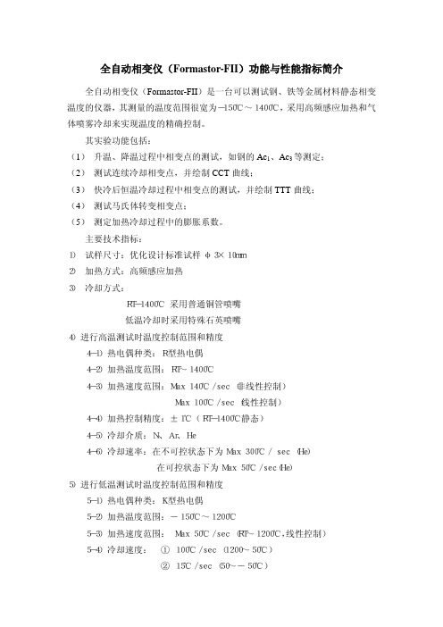
全自动相变仪(Formastor-FII)功能与性能指标简介全自动相变仪(Formastor-FII)是一台可以测试钢、铁等金属材料静态相变温度的仪器,其测量的温度范围很宽为-150℃~1400℃,采用高频感应加热和气体喷雾冷却来实现温度的精确控制。
其实验功能包括:(1) 升温、降温过程中相变点的测试,如钢的Ac1、Ac3等测定;(2) 测试连续冷却相变点,并绘制CCT曲线;(3) 快冷后恒温冷却过程中相变点的测试,并绘制TTT曲线;(4) 测试马氏体转变相变点;(5) 测定加热冷却过程中的膨胀系数。
主要技术指标: 1) 试样尺寸:优化设计标准试样φ3×10mm 2) 加热方式:高频感应加热 3) 冷却方式: RT-1400℃ 采用普通铜管喷嘴 低温冷却时采用特殊石英喷嘴 4)进行高温测试时温度控制范围和精度 4-1)热电偶种类:R型热电偶 4-2)加热温度范围:RT~1400℃ 4-3)加热速度范围:Max 140℃/sec (非线性控制) Max 100℃/sec (线性控制) 4-4)加热控制精度:±1℃(RT-1400℃静态) 4-5)冷却介质:N、Ar、He 2 4-6)冷却速率:在不可控状态下为Max 300℃/ sec (He) 在可控状态下为Max 50℃/sec(He) 5)进行低温测试时温度控制范围和精度 5-1)热电偶种类:K型热电偶 5-2)加热温度范围:-150℃~1200℃ 5-3)加热速度范围: Max 50℃/sec (RT~1200℃,线性控制) 5-4)冷却速度: ① 100℃/sec (1200~50℃) ② 15℃/sec (50~-50℃) ③ 1.5℃/sec (-50~-100℃) ④ 0.8℃/sec (-100~-150℃) 5-5) 温度控制精度:①±1℃(室温~1200℃静态) ②±5℃(室温~-150℃静态) 5-6) 冷却介质:①真空,惰性气体(RT~1200℃) ② He (RT~-150℃) 6)膨胀测量 6-1)检测系统: 差动相变测定系统 6-2)测量范围: 4 挡 0.5, 0.2, 0.1, 0.05mm /±5V 6-3)测量精度: ±1.0% 6-4)输出电压: ±5V 6-5)稳定性:室温下 1μ/4hours(室温变化小于5%) 低温时 5μ/20minutes(室温变化小于5%) 7)真空系统性能 7-1)机械泵: 162 (50Hz) / 197 (60 Hz) l /min. 7-2)扩散泵: 360 L /sec ( Dia. 3 inches) 7-3)排气速率: Max. 1.3 x 10⁻² Pa / 15 min. 7-4)可得真空度: Order of 10-3 Pa 7-5)真空阀门: 气动控制系统 8)软件要求 8-1)给出常用设定参数或输入自己想要的测试参数,自动控制测试过程的进行 8-2)除了给出纸张记录曲线还能自动给出数字化CCT 图、TTT 图曲线 8-3)所有数据和excel 数据兼容 全自动相变仪(Formastor-FII)操作规程一、开机步骤1、打开总电源;2、打开循环水泵电源;3、打开压缩空气和冷却气体的气阀开关;4、扳动主设备面板上的“MAIN”开关,使其处于“开”状态;5、扳动主设备面板上的“CONTROL”开关,使其处于“开”状态;6、启动操作台上的电脑;7、点击主设备面板上“RP ON/OFF”按钮,启动机械泵;8、点击主设备面板上“DP ON/OFF”按钮,等待30分钟后,启动扩散泵;二、连续冷却转变试验(即CCT试验)的操作步骤注:一般冷却气体为氮气,热电偶类型为R型。
三菱FX2N控制器,FX1N系列PLC产品介绍,FX1s系列,fx2nc控制器

三菱控制器介绍与型号,三菱控制器详细规格FX2N控制器产品介绍:FX2n系列是FX系列PLC家族中最先进的系列。
由于FX2n系列具备如下特点:最大范围的包容了标准特点、程式执行更快、全面补充了通信功能、适合世界各国不同的电源以及满足单个需要的大量特殊功能模块,它可以为你的工厂自动化应用提供最大的灵活性和控制能力。
FX2N控制器交流电源、24V直流输入类型:模型I/O总数输入输出尺寸 mm(英寸)(宽)x(厚)x(高)数目类型数目类型FX2N-16MR-00116 8 漏型8 继电器130x87x90(5.12x3.4x3.5)FX2N-16MT 晶体管FX2N-32MR-00132 16 漏型16 继电器150x87x90(5.9x3.4x3.5)FX2N-32MT 晶体管FX2N-48MR-00148 24 漏型24 继电器182x87x90(7.2x3.4x3.5)FX2N-48MT 晶体管FX2N-64MR-00164 32 漏型32 继电器220x87x90(8.7x3.4x3.5)FX2N-64MT 晶体管FX2N-80MR-00180 40 漏型40 继电器285x87x90(11.2x3.4x3.5)FX2N-80MT 晶体管FX2N-128MR-001128 64 漏型64 继电器350x87x90(13.8x3.4x3.5)FX2N-128MT 晶体管24V直流电源、24V直流输入类型:模型I/O总数输入输出尺寸 mm(英寸)(宽)x(厚)x(高)数目类型数目类型FX2N-32MR-D32 16 漏型16 继电器150x87x90(5.9x3.4x3.5)FX2N-32MT-D 晶体管FX2N-48MR-D48 24 漏型24 继电器182x87x90(7.2x3.4x3.5)FX2N-48MT-D 晶体管FX2N-64MR-D64 32 漏型32 继电器220x87x90(8.7x3.4x3.5)FX2N-64MT-D 晶体管FX2N-80MR-D80 40 漏型40 继电器285x87x90(11.2x3.4x3.5)1200 注:1. 表示适用电机容量足以使用三菱标准4极电机时的最大适用容量。
Cutler-Hammer AT3 自动转换开关商品介绍 说明书

Product DescriptionThe Cutler -Hammer ா AT3 Automatic Transfer Switch from Eaton’s electri-cal business is designed to provide unmatched performance, reliability and versatility for critical standby power applications. AT3 switches are equipped with the high-performance ATC-300 digital transfer controller for rock-solid monitoring, status reporting and transfer control operation. Superior design and robust construction make the AT3the industry benchmark for critical and distributed power systems.Electrical RatingsI Ratings 30 – 1000 amperes.I 2, 3 or 4-poles.I Up to 600 Vac, 50/60 Hz.I NEMA ா 1, 3R, 12, open.I Suitable for emergency and standby systems (all loads).I UL ா 1008 listed.ICSA ா C22.2 No. 178 certified.Industrial Design HighlightsI Double-throw, mechanicallyinterlocked transfer mechanism.I High withstand and closing ratings.ISeismic Zone 4 qualified (BOCA ா, CBC, IBC, UBC ா).Standard FeaturesIAuxiliary relay contacts:I Source 1 Present 2NO & 2NC I Source 2 Present 2NO & 2NC ISwitch position indication contacts:I Source 1 Position 1NO & 1NC I Source 2 Position 1NO & 1NCISource 1 & Source 2 sensing:I Undervoltage/under frequency I Overvoltage/over frequency I 3-phase rotation protectionI 3-phase voltage unbalance/loss I Pre-transfer signal contacts 1NO/1NC.I Go to Emergency (Source 2).I Seven field programmable time delays.ILCD-based display for program-ming, system diagnostic and Help message display.IMimic diagram with source available and connected LED indication.I Time-stamped history log.I System test pushbutton.IProgrammable plant exerciser —OFF , daily, 7, 14, 28-day interval selectable run time 0 – 600 min-utes no load/load with failsafe.ISafe manual operation under full load with permanently affixed operating handle.Optional FeaturesISuitable for Use as Service Equipment in the standard enclosure size.IAvailable TVSS surge suppres-sion for power/controller, engine start circuit, phone and cable connections.I Integrated distribution panels.IField-selectable multi-tap trans-former panel permits operation on a wide range of system voltages.I Integral overcurrent protection.I Space heater with thermostat.I Ammeter — load side.IStainless steel cover for controller.Service Entrance EquipmentThe AT3 transfer switch is available as rated as Suitable for Use as Service Equipment in the standard enclosure size. Cutler-Hammer Service Equip-ment rated transfer switches with integral overcurrent protection may be installed at the point of ServiceEntrance without the need for separate upstream disconnect devices and additional power connections.Eaton Electrical Inc.1000 Cherrington Parkway Moon Township, PA 15108United States tel: 1-800-525-2000©2005 Eaton Corporation All Rights Reserved Printed in USAPub. No. PA01602002E / Z2897April 2005CSA is a registered trademark of the Canadian Standards Association. Cutler -Hammer is a federally registered trademark of Eaton Corporation. NEMA is the registered trademark and service mark of the National Electrical Manufacturers Association. UL is a federally registered trademark of Underwriters Laboratories Inc. BOCA is a registered trademark of Building Officials and Code Administrators International, Inc. Uniform BuildingCode (UBC) is a trademark of the International Conference of Building Officials (ICBO).Table 1. UL 1008 Withstand and Close-On Ratings (kA)ᕃ240 Vac.Switch Rating Amperes UL 1008 3-Cycle “Any Breaker” Rating Rating When Used With Upstream Fuse240 Vac 480 Vac 600 Vac Maximum Fuse Rating Fuse Type 600 Vac30 – 100 150150 – 225 225100100100100656565 ᕃ6525252525 200 400 400 400J, T J, T J, T J, T 200200200200 300 400 600100100100656565252525 400 6001200J, T J, T J, T 200200200 800100065 655050252516001600L L200200Table 2. Wall Mount Transfer Switch Standard Terminal Data for Power Cable ConnectionsNote: All terminals suitable for copper or aluminum conductors.Note: For alternate terminal sizes, contact Eaton.Switch Rating Amperes Breaker Frame Line Side (Normal and Standby Source)LoadConnection Neutral Connection 30 – 100 150 – 225 150 – 225 225 – 300HFD HFD HKD HKD (1) #14 – 1/0(1) #6 – 300(1) #3 – 350(1) #3 – 350(1) #14 – 1/0(1) #6 – 300(1) #6 – 360(1) #6 – 350(3) #14 – 1/0(3) #4 – 300(3) #4 – 350(3) #4 – 350 400 600 600HLD HLD HMDL (1) 4/0 – 600(2) 3/0 – 350(2) #1 – 500(2) #1 – 500(2) #1 – 500(2) #1 – 500(6) 250 – 350(6) 250 – 350(12) 4/0 – 500 600 (4-pole) 800 8001000NB HMDL HNB HNB(3) 3/0 – 400(3) 3/0 – 400(4) 4/0 – 500(4) 4/0 – 500(3) 3/0 – 400(3) 3/0 – 400(4) 4/0 – 500(4) 4/0 – 500(3) 3/0 – 400(12) 4/0 – 500(12) 4/0 – 500(12) 4/0 – 500Table 4. AT3 Transfer Switch Catalog Numbering SystemFD = 200 and 225 amperes, LD = 600 amperes, MD = 800 amperes for 240/120 Vac single-phase, 3-wire and 208Y/120 Vac 3-phase, 4-wire systems only.Table 3. Dimensions in Inches (mm) and Approximate Shipping in Lbs. (kg)ᕄ240/120 volt, single-phase, 3-wire or 208 volt, 3-phase, 4-wire systems only.ᕅWith multi-tap voltage selection panel.Switch TypeAmperesEnclosure Gutter Space Bolt PatternWeight Lbs. (kg)A (Height)B (Width)C (Depth)D (Width)E (Depth)G (Horizontal)H (Vertical)HFD ᕄHFD ᕄHFD ᕅ30 – 100150 – 225 30 – 10047.74 (1213.0)47.74 (1213.0)47.74 (1213.0)20.81 (528.6)20.81 (528.6)20.81 (528.6)17.22 (437.0)17.22 (437.0)17.22 (437.0)8.00 (203.2)8.00 (203.2)8.00 (203.2)4.00 (101.6)4.00 (101.6)4.00 (101.6)10.75 (273.0)10.75 (273.0)10.75 (273.0)46.44 (1180.0)46.44 (1180.0)46.44 (1180.0)232 (105)232 (105)240 (190)HFD ᕅHFD ᕄHKDHKD150150 – 225150 – 22530047.74 (1213.0)35.61 (904.0)48.00 (1219.2)56.00 (1422.4)20.81 (528.6)20.06 (509.5)20.81 (528.6)20.81 (528.6)17.22 (437.0)13.34 (339.0)18.40 (467.4)18.40 (467.4)8.00 (203.2)8.00 (203.2)8.00 (203.2)8.00 (203.2)4.00 (101.6)4.00 (101.6)4.00 (101.6)4.00 (101.6)10.75 (273.0)10.75 (273.0)11.00 (279.4)11.00 (279.4)46.44 (1180.0)34.31 (904.0)45.50 (1155.7)53.50 (1358.9)240 (190)150 (68)305 (138)295 (134)HLD HLD ᕄHMDL40060060053.00 (1346.0)64.00 (1625.6)76.74 (1949.2)25.81 (655.6)25.81 (655.6)25.81 (655.6)18.40 (467.4)18.40 (467.4)19.50 (495.3)8.00 (203.2)8.00 (203.2)8.00 (203.2)4.00 (101.6)4.00 (101.6)4.00 (101.6)16.00 (406.4)16.00 (406.4)16.00 (406.4)51.50 (1308.0)62.50 (1588.0)75.15 (1908.8)425 (193)475 (214)480 (218)HMDL ᕄHNB 800800 – 100076.74 (1949.2)76.74 (1949.2)25.81 (655.6)25.81 (655.6)19.50 (495.3)19.50 (495.3)8.00 (203.2)8.00 (203.2) 4.00 (101.6)4.00 (101.6)16.00 (406.4)16.00 (406.4)75.15 (1908.8)75.15 (1908.8)510 (232)540 (245)Typical (225 – 1000 A) Vertical Design Transfer Switch Equipment (Door Open and Deadfront Cover Removed)Power Panel NormalPower Source Molded Case Switch VoltageSelection Panel (Domestic)Emergency Power Source Molded Case SwitchMotorBrake BoardTransfer Mechanism Indicator Wheel Manual Operating Handle NeutralConnections Load Lugs (T op Entry)Service Disconnect。
FANUC I系列硬件结构-文档资料
FANUC-16i (一体型系统)
FANUC-18i (分离型系统)
FANUC—21i系统 26
1. FANUC—16i/18I/21i系统特点
(1)通过使用高速RISC处理器,可以在进行纳米插补的同时, 以适合于机床性能的最佳进给速度进给加工。 (2)超高速伺服串行通信(FSSB)。
(3)丰富的网络功能。
CNC单元
2
显示装置与操作面板
FANUC—OC 系统的主要控制功能
具有丰富的加工功能 具有刀具寿命管理、极坐标插补、圆柱插补、多边形加
工等特有的控制功能,并且提供了专用的定制型用户宏
程序,从而能够容易地实现一些特殊的机械加工。
CNC控制伺服轴数
最大为6轴
联动伺服轴数
最大为4轴
主轴控制数和驱动装置 一个模拟量主轴或2个串行数字主轴
FANUC Series 0i Mate - MODEL B
0i Mate - MODEL B 是一款具有很高性价比 的CNC系统.该系统功能强大, 最多可控制三轴.
・售价低廉的功能包提供了很多高效的 CNC功能
・最大控制轴数
3 轴 (MB)
2 轴 (TB)
・最大控制主轴电机数
1个
・可连接的伺服电机 αCi , β/ βi伺服电机
列的FANUC Series O-MC,用于平面磨床系列的FANUC Series
3
O-GSC,用于内、外磨床系列的FANUC Series O-GCC。
FANUC—OD 系 统的 主要 控制 功能
取消了特有的加工功能 如极坐标插补、圆柱插补、多边形加工等特 有的
控制功能。
CNC控 制 伺 服 轴 数
采用α 系列驱动
NAMUR接口1 4英寸和1 2英寸高流气动阀G1 4英寸和G1 2英寸用于控制空气驱动器应用说明书

aerospace climate control electromechanical filtrationfluid & gas handling hydraulics pneumatics process control sealing & shieldingD2D1"2""4"MFTD4D3Ra 3.2Description of ApplicationsControl of single or double acting pneumatic actuators, in safe or dangerous areas.NAMUR Interfaces 1/4" & 1/2"Th e interface design is conform to the NAMURstandard and to the VDI/VDE 3845 recommendations of the actuator industry. It allows a compact design of the actuator/valve unit. In case of a 3/2 function,the air of the actuator spring chamber also fl owsthrough the pilot valve (re-breather function).Th is prevents corrosion of the actuator springs.Market DescriptionProcess industriesChemical, Petrochemical industries Oil & GasWater & Sewage Pulp & Paper Food & BeveragePharmaceutical industryPowder Dosing-Transportation Air DryersF T D1 D2 D3 D4 min. M mm mm mm Mm mm M5 1/4 32 24 8 12 M5 M6 1/2 45 40 10 16 M6F: 2 mounting holes - T: 2 actuators control port - M: 2 holes for dowel pins● High fl ow: 1.250 l/min (1/4"), 3.000 l/min (1/2")● Compact design ● Long life expectancy● N3x series compatible with any Parker Lucifer coil(ATEX or not) of electrical group 2 (8/9 W coils)● Fail safe standard● Reduced inventory (3/2 & 5/2 functions with the samevalve on 341Nx5 series)● Mechanical part of the valve ATEX certifi ed accordingstandard EN 13463-1 & -5Function: 3/2 , 5/2, 3/2 <=> 5/2 and 5/3 valves.Manual override: Standard on all versions.Design: Solenoid operated spool valve with combined spring and air return & external air pressure operated versions.Mounting:For direct mounting on NAMUR interface ¼" & ½".Mounting position: I ndifferent.Material specifi cations: Aluminium body. Internal parts from stainless steel.Sealing material from NBR.Range of admissible pressure drop: Δp min. = see table. Δp max. = 10 bar.Media:Dry or lubricated air.Fluid temperature: Min. 0°C Max. + 50°C Ambient temperature: -10°C to +50°CElectrical part: N0x series are compatible with 22mm coil 496131 / 496482 / 496637 SeriesN3x series are compatible with 32/37/40 mm coils part of electrical group 2 (8/9W), including 481865 / 495870 / 495905 Series.Solenoid duty: 100% ED.Voltage: 481865 coil: 12 VDC , 24 VDC , 48 VDC , 110VDC, 24 V / 50 AC, 48 V / 50 AC,110 V / 50 AC, 220-230V/50 AC, 115 V / 60 Hz AC, 230 V / 60 AC.Voltage tolerance: ± 10% of nominal for 481865 coil.Class of insulation material: Class F for 481865 coil.Standards:Mechanical ATEX conform to EN 13463-1 & -5.Customer Value PropositionGeneral Information1313135135135135135G1/4" SeriesSolenoid Operated VersionsN03-N05 Series with 22 mm Coil3/2 Solenoid operated - Combined spring & air return (monostable)1/4 7 1250 2.5 10 10 50 NBR 331N03 - 496131 3 3 300 11/4 7 1250 2.5 10 10 50 NBR 331N03 - 496482 3 3 300 11/4 7 1250 2.5 10 10 50 NBR 331N03 - 496637 3 3 30015/2 Solenoid operated - Combined spring & air return (monostable)1/4 7 1250 2.5 10 10 50NBR 341N03 - 496131 3 3 300 21/4 7 1250 2.5 10 10 50 NBR 341N03 - 496482 3 3 300 2 1/47 1250 2.5 10 1050NBR 341N03 - 496637 3 3 30023/2 <=> 5/2 with conversion plate - Solenoid operated Combined spring & air return (monostable)1/4 7 1250 2.5 10 10 50NBR 341N05 - 496131 3 3 310 3 1/4 7 1250 2.5 10 10 50 NBR 341N05 - 496482 3 3 310 3 1/47 1250 2.5 10 1050NBR 341N05 - 496637 3 3 31035/2 Solenoid operated and return (bistable)1/47 1250 2.5 10 10 50NBR 347N03 - 496131 3 3 430 41/4 7 1250 2.5 10 10 50 NBR 347N03 - 496482 3 3 430 4 1/47 1250 2.5 10 1050NBR 347N03 - 496637 3 3 43045/3 W1 closed in center position - Solenoid operated and return1/4 7 1250 2.5 10 10 50NBR 342N03 - 496131 3 3 430 41/4 7 1250 2.5 10 10 50 NBR 342N03 - 496482 3 3 430 4 1/47 1250 2.5 10 1050NBR 342N03 - 496637 3 3 43045/3 W3 exhausted in center position Solenoid operated and return (bistable)1/4 7 1250 2.5 10 10 50NBR 343N03 - 496131 3 3 430 41/4 7 1250 2.5 10 10 50 NBR 343N03 - 496482 3 3 430 4 1/47 1250 2.5 10 1050NBR 343N03 - 496637 3 3 4304Please consult the "How to Order" part at the end of each coil chapter.Dimensions Reference 3Dimensions Reference 4404040403232322222222232326767676767505050505013 13 13 13 13 13 13 13 44 44 44 222236.536.5G1/4" (2x)G1/4" (3x)G1/4" (3x)G1/4" (3x)M5M5M5M52323232336,52424242423232323868610290 121414101212344355513332227.27.27.27.2Dimensions Reference 1Dimensions Reference 2131351351352440403232879738381313 19.519.513132222 24243232DIN 43650ADIN 43650A G1/8"G1/8"2222 1001302323232324 24 14 12245533G1/4" (3x)G1/4" (3x)M5M52222327.27.5Solenoid Operated VersionsN33-N35 Series with 32 / 37 / 40 mm CoilAdmissible Max. admissible differential fl uidPort size Orifi ce Q N pressure temperatureSeat Reference Consumption Weight Elect. Dim. (bar) (ºC)disc number Power (g) Group Ref.(Watt) max. Min. = 0ºC G mm L/min min DC= AC~ Air & Valve Housing Coil DC AC Neutral gases3/2 <=> 5/2 with conversion plate - Solenoid operated Combined spring & air return (monostable)1/4 7 1250 2.5 10 10 50NBR 341N35 2995 481865 9 8 480 2 5 1/4 7 1250 2.5 10 10 50 NBR - 2995 495870 9 8 700 - 2 1/47 1250 2.5 10 1050NBR - - 495905 8 8 740 - 25/2 Solenoid operated and return (bistable)1/47 1250 2.5 10 10 50NBR 347N33 2995 481865 9 8 750 2 6 1/4 7 1250 2.5 10 10 50 NBR - 2995 495870 9 8 1190 2 - 1/47 1250 2.5 10 1050NBR - - 495905 8 8 1270 2 -5/3 W1 closed in center positionSolenoid operated and return (bistable)1/4 7 1250 2.5 10 10 50NBR 342N33 2995 481865 9 8 750 2 6 1/4 7 1250 2.5 10 10 50 NBR - 2995 495870 9 8 1190 2 - 1/47 1250 2.5 10 1050NBR - - 495905 8 8 1270 2 -Please consult the "How to Order" part at the end of each coil chapter.Dimensions Reference 5Dimensions Reference 61313513513540404032323213 13 13 13131344 22 22 22 22 86868623232323232324 24 24 355133G1/4" (2x)G1/4" (3x)G1/4" (3x)G1/8G1/8G1/8M5M5M52222227.27.27.2External Pressure Air Operated Series 5xx N03 SeriesAdmissible Max. admissible differential fl uidPort size Orifi ce Q N pressure temperatureSeat Reference Consumption Weight Dimensions (bar) (ºC)disc number Power (g) Reference(Watt) max. Min. = 0ºC G mm L/min min DC= AC~ Air & Valve Housing Coil DC AC Neutral gases3/2 External pressure air operatedCombined spring & air return (monostable)External pressure supply 2.5 to 10 bar1/4 7 1250 2.5 10 10 50 NBR 531N03 - w/o - - 21075/2 external pressure air operatedCombined spring & air return (monostable)External pressure supply 2.5 to 10 bar1/47 1250 2.5 10 1050NBR 541N03 - w/o - - 21085/2 external pressure air operatedExternal pressure air return (bistable)External pressure supply 2.5 to 10 bar1/47 1250 2.5 10 1050NBR 547N03 - w/o - - 24095/3 W1 closed in center position - External pressure air operatedExternal pressure air return (bistable)External pressure supply 2.5 to 10 bar1/47 1250 2.5 10 1050NBR 542N03 - w/o - - 2409Dimensions Reference 7Dimensions Reference 8Dimensions Reference 913135135Solenoid Operated VersionsN34 Series with 32 / 37 / 40 mm CoilAdmissible Max. admissible differential fl uidPort size Orifi ce Q N pressure temperatureSeat Reference Consumption Weight Elect. Dim. (bar) (ºC)disc number Power (g) Group Ref.(Watt) max. Min. = 0ºC G mm L/min min DC= AC~ Air & Valve Housing Coil DC AC Neutral gases3/2 Solenoid operatedCombined spring & air return (monostable)1/2 12 3000 2.5 10 10 50NBR 331N34 2995 481865 9 8 910 2 10 1/2 12 3000 2.5 10 10 50 NBR - 2995 495870 9 8 1130 2 - 1/212 3000 2.5 10 1050NBR - - 495905 8 8 1170 2 -5/2 Solenoid operatedCombined spring & air return (monostable)1/2 12 3000 2.5 10 10 50NBR 341N34 2995 481865 9 8 900 2 11 1/2 12 3000 2.5 10 10 50 NBR - 2995 495870 9 8 1120 2 - 1/212 3000 2.5 10 1050NBR - - 495905 8 8 1160 2 -5/2 Solenoid operated and return (bistable)1/212 3000 2.5 10 10 50NBR 347N34 2995 481865 9 8 1240 2 12 1/2 12 3000 2.5 10 10 50 NBR - 2995 495870 9 8 1680 2 - 1/212 3000 2.5 10 1050NBR - - 495905 8 8 1760 2 -Please consult the "How to Order" part at the end of each coil chapter.Dimensions Reference 10Dimensions Reference 11Dimensions Reference 1213135External Pressure Air Operated Series5 xx N04 SeriesAdmissible Max. admissibledifferential fl uidPortsize Orifi ce QNpressure temperatureSeat ReferenceConsumptionWeightDimensions(bar)(ºC)disc number Power (g)Reference(Watt)max. Min. = 0ºCG mm L/min min DC= AC~ Air & Valve Housing Coil DC ACNeutralgases3/2 External pressure air operatedCombined spring & air return (monostable)External pressure supply 2.5 to 10 bar1/2 1230002.510 10 50 NBR531N04 - w/o - - 620 135/2 external pressure air operatedCombined spring & air return (monostable)External pressure supply 2.5 to 10 bar1/2 12 3000 2.5 10 10 50 NBR541N04 - w/o - - 600 14 Dimensions Reference 13Dimensions Reference 14● Power: 3W● Insulation Class: F (155°C)● Degree of Protection: IP65 (with plug)● Duty Cycle: 100% ED ●Ambient Temperature:-10°C to 50°C3 different types are available:● Ref. 496131for a safe area without plug ● Ref. 496482for a safe area with plug ● Ref. 496637for an ATEX area Zone 22Coils and Spare Parts Informations 496637 coil series with connection 2P + G when mounted together with the supplied Pg9 plug (delivered with the coil) are suitable for use in dangerous areas (dust Zone 22) according to the European directive ATEX 94/9/C. Protection mode: Ex tD A22 IP65 - T95°CAvailable Safe area Safe area ATEX Voltageswithout DIN plug with DIN plug Zone 22 EX II 3DOrder Order Order Code Code Code12VDC 496131 C1 496482 C1 496637 C124VDC 496131 C2 496482 C2 496637 C2 48VDC 496131 C4 496482 C4 496637 C4 110VDC 496131 C5 496482 C5 496637 C5 24/50-60VAC 496131 P0 496482 P0 496637 P0 48/50-60VAC 496131 S4 496482 S4 496637 S4 110/50-60VAC 496131 P2 496482 P2 496637 P2 115/60VAC 496131 K8 496482 K8 496637 K8230/50-60VAC 496131 P9496482 P9496637 P9How to OrderThe housing kit is already included into the coil reference, so it’s not needed to add it in the order code:Valve Reference Number - Coil Reference - Voltage code = Order codeExample: 341N03 - 496131 C2Valves and coils may be ordered also separately.Coils 22 mm for N03-N05 SeriesSafe Area & ATEX Zone 22 Ref. 496131 / 496482 / 496637Th ese coils with connection for 2 P+G DIN 43650 B plug are encapsulated in synthetic material, conform to the IEC/CENELEC safety standards and comply with European low voltage directive73/23/EC .S a f e A r e a & A T E X Z o n e 22● Power: 8W (AC) 9W (DC)● Insulation Class: F (155°C)● Degree of Protection: IP65 (with plug)● Duty Cycle: 100% ED● Voltage Tolerance -10%/+10%● Ambient Temperature -40°C/+50°C◗ The application can be limited alsoby the temperature range of the valveAvailable Order Voltages Code 12VDC 481865 C1 24VDC 481865 C2 48VDC 481865 C4 110VDC 481865 C5 24/50VAC 481865 A2 48/50VAC 481865 A4 110/50VAC 481865 A5 220-230/50VAC 481865 3D 380/50VAC 481865 A9 24/60VAC 481865 B2 115/60VAC 481865 K8 230/60VAC481865 J3How to OrderThis coil must be used together with a housing kit which includes a nut, a plate, and a washer. Housing Kit Order Code: 2995Valve Reference Number - Housing Reference - Coil Reference - Voltage Code = Order CodeExample: 341N35 - 2995 - 481865 C2Coils 32 mm / 37 mm / 40 mm for N33-N34-N35 Series Safe Area Ref. 481865N3x series are compatible with any Parker Lucifer coil part of electrical group 2. Th at group includes many diff erent coils for safe areas or areas submitted to ATEX certifi cations. Th ese coils are of the 8/9W class. Th ese coils with connection for 2P+G DIN 43650 A plug are encapsulated in synthetic material, conform to the IEC/CENELEC safety standards and comply with European low voltage directive 73/23/EC.S a f e A r e adtCoils and Spare Parts Informations ●Power: 8W● Insulation Class: F (155°C)● Degree of Protection: IP67 (with 4538 housing)● Duty Cycle: 100%●Voltage Tolerance -10%/+10%● Ambient Temperature -40°C/+50°C ◗ The application can be limited alsoby the temperature range of the valveHow to OrderValve Reference Number - Housing Reference - Coil Reference - Voltage Code = Order CodeExample: 331N34 - 4538 - 481000C2Housing 4538This enclosure is dust and water proof. It corresponds to the protection degree IP67 according to IEC/EN60529. Corrosion resistant, the metallic housing offers good protection for the coil against shocks. It can be 360° orientable. This housing must be equipped with 481000 series coil.Material: galvanized passivated steel - Degree of protection IP67 according to IEC/EN 60529 - Electrical connection: cable connection by cable gland according to DIN46320. Cable with outer diameter 6.5-13.5 mm (M20x1.5) can be simply sealed using a rubber gland resilient sealing rings. The enclosure is internally and externally fi tted with grounding and earthing screw terminals.Coils 32 mm / 37 mm / 40 mm for N33-N34-N35 Series Safe Area Coil 481000 Series with 4538 Watertight and dust proof housing IP67 Ref. 481000Coil 481000 series is encapsulated in synthetic material. Electrical connection is made with screw terminals for wire up to 1.5 mm. Th is coil conforms to the IEC/CENELEC safety standards and complies with European low voltage directive 73/23/EC. It must be used with a metallic housing.S a f e A r e a●II 3 G - Ex nAC IIC T3 / T4● II 3 D - Ex tD A22 IP65 - T 195°C / T 130°C● Power: 8W (AC) 9W (DC)● Insulation Class: F (155°C)● Degree of Protection: IP65 (with plug)● Duty Cycle: 100% ED● Voltage Tolerance -10%/+10%●Ambient temperature◗ T3 (gaz) T 195°C (dust) -40°C/+65°C ◗ T4 (gaz) T 130°C (dust) -40°C/+50°C◗ The application can be limited alsoby the temperature range of the valveAvailable Order Voltages Code 24VDC 495870 C2 48VDC 495870 C4 110VDC 495870 C5 24/50VAC 495870 A2 48/50VAC 495870 A4 110/50VAC 495870 A5 220-230/50VAC495870 3DA T E X Z o n e 2-22How to OrderThis coil must be used together with a housing kit which includes a nut, a plate, and a washer. Housing kit order code: 2995Valve Reference Number - Coil Reference - Voltage code = Order codeExample: 331N34 - 2995 - 495870 A5Coils 32 mm / 37 mm / 40 mm for N33-N34-N35 Series ATEX Zone 2-22 Ref. 495870Th is coil with connection 2P+G - when mounted together with the supplied Pg 9 plug (delivered with the coil), is suitable for use in Gas and Dust dangerous areas (Zone 2-22), according to the European directive ATEX 94/9/C . Certifi cate LCIE 05 ATEX 6003 X - Protection mode: non sparking / limited energy solenoid0081II 3 G-DA T E X z o n e 1-21●II 2 G - Ex d mb IIC T4● II 2 D - Ex tD A21 IP67 - T 130°C● Insulation Class H (180°C)● Power: 8W (AC-DC)● Degree of Protection IP67● Duty Cycle 100%● Voltage Tolerance -10%/+10%● Ambient Temperature: -40°C/+65°C◗ The application can be limited alsoby the temperature range of the valveAvailable Order Voltages Code 24VDC 495905 C2 48VDC 495905 C4 110VDC 495905 C5 24/50VAC 495905 A2 48/50VAC 495905 A4 110/50VAC 495905 E5 220-230/50VAC 495905 3D115/60 495905 E5240/60 495905 B8Electric connection is done in the connection box on an easily accessible connector terminals.M20x1.5 Cable glandHow to OrderThe housing kit is already included into the coil reference, so it’s not needed to add it in the order code:Valve Reference Number - Coil Reference - Voltage code = Order codeExample: 347N33 - 495905 C2Coils 32 mm / 37 mm / 40 mm for N33-N34-N35 Series ATEX Zone 1-21 Ref. 495905Th is coil is suitable for use in Gas and Dust dangerous areas (Zone 1-21), according to the European directive ATEX 94/9/C . It’s also IECEx certifi ed according to the IECEx Scheme. Certifi cate LCIE 02 ATEX 6451 X - Protection modes: Explosionproof solenoids with fl ameproof enclosure / encapsulation "d mb"0081II 2 G/Dnct c io o n n bo ox al a l s.s .Available OrderOrder Voltages Code Code 6VDC 483371 C0 - 12VDC 483371 C1 - 24VDC 483371 C2 494040 C236VDC 483371 C3 - 48VDC 483371 C4 - 60VDC 483371 M3 - 110VDC 483371 C5 - 125VDC 483371 3N 494040 3N 220VDC 483371 C7 494040 C712/50VAC 483371 A1 - 24/50VAC 483371 A2 494040 A248/50VAC 483371 A4 - 110-115/50VAC 483371 OA 494040 OA 220-230/50 483371 3D 494040 3D24/60VAC 483371 B2 - 110-115/60VAC 483371 6J - 220-240/60VAC 483371 4K-380/50-440/60VAC -494040 5PHow to OrderThe housing kit is already included into the coil reference, so it’s not needed to add it in the order code:Valve Reference Number - Coil Reference - Voltage code = Order codeExample: 347N33 - 483371C2Coils 32 mm / 37 mm / 40 mm for N33-N34-N35 Series ATEX Solutions Zone 1-21 Ref. 483371 & 494040Th ese coils are suitable for use in Gas and Dust dangerous areas (Zone 1-21), according to the European directive ATEX 94/9/C. Protection mode:encapsulated electrical parts with increased safety.483371…DC: 24V / 400mA - 48V / 250mA 110V / 100mAAC: 24V / 630mA - 48V / 315mA 110/115V / 160mA 220/230V / 80mA494040…DC: 24V / 400mA - 125V / 80mA48V /220V - 63mAAC: 24V / 630mA - 48V / 315mA 110/115V / 160mA220/230V / 80mAA T E X Z o n e 1-21Reference 483371 or HZ06 494040 or HZ23Approval LCIE 02 ATEX 6011 X LCIE 02 ATEX 6013 X Type of Gas II 2 G - Ex e mb II T4 II 2 G - Ex e mb II T3 II 2 G - Ex e mb II T4 protection Dust II 2 D - Ex tD A21 T 130°C II 2 D - Ex tD A21 T 195°C II 2 D - Ex tD A21 T 130°C Degree of protection I P67 I P67 Ambiant temperature -40°C to +65°C -40°C to +90°C -40°C to +65°CThe application is limited also by the temperature range of the valveClass of insulation F (155°) H (180°) Electrical connection By special cable gland or M20x1.5 "Ex e" on screw terminals for wires up to 1.5 mm². Cables with outside diameter 6.5 mm to 13.5 mm can be simply sealed using the rubber gland with resilient sealing rings supplied. Elect. DC Pn (hot) 8 W 8 W Power P (cold) 20°C 9 W 9 W AC Pn (holding) 8 W 8 W 32 VA (9 W) 32 VA (9 W) Voltage tolerance Tolerance -10/ +10% of the nominal voltageSolenoid duty Continuous duty solenoid (ED 100%)Fuses: Both electrical 483371… and 494040… parts have to be connected in series with asafety fuse according to CEI 60127-3.Spare Parts Mounting Kit and AccessoriesExhaust Flow RegulatorsMaterial Body: Brass Filter element: Sintered bronze Spring: Stainless Steel Seal: NBRG1/8" Order code: 496551 G1/4" Order code: 496552 G1/2" Order code: 496553Kit for G1/4" Modelswithout conversion plate (N x 3 Series)Kit includes the 2 mounting screws M5 x 25 A2, the dowel pin M5 x 10 A2, the 2 O-rings NBR 15 x 2.5Order code: 496132Kit for G1/2" Models (N x 4 Series)Kit includes the 2 mounting screws M6 x 35 A2, the dowel pin M6 x 12 A2, the 2 O-rings NBR 24 x 3Order code: 496133Kit for G1/4" Modelswith conversion plate (N x 5 Series)Kit includes the 2 mounting screws M5 x 35 A2, the dowel pin M5 x 20 A2,the conversion plate equipped with its seals Order code:496742Connector for 32 mm CoilConnector DIN43650 AA Pg9 2P+E Order code: 486586Housing for 22 mm CoilPlastic nut with O-ring Order code: 3125Connector for 22 mm CoilConnector DIN43650 AB Pg9 2P+E Order code:481043NotesAEROSPACEKey Markets• Aircraft engines• Business & general aviation• Commercial transports• Land-based weapons systems• Military aircraft• Missiles & launch vehicles• Regional transports• Unmanned aerial vehiclesKey ProductsFlight control systems& compon ntsFluid conveyance systemsFluid metering delivery& atomization devicesFuel systems & componentsHydraulic systems & componentsInert nitrogen generating systemsPneumatic systems & components• Wheels & brakesCLIMATE CONTROLKey MarketsAgricultureAir conditioningFood, beverage & dairy• Life sciences & medicalPrecision coolingProcessingTransportationKey ProductsCO2 controlsElectronic controllersFilter driersHand shut-off valvesHose & fi ttingsPressure regulating valvesRefrigerant distributorsSafety relief valvesSolenoid valvesThermostatic expansion valvesFILTRATIONKey MarketsFood & beverageIndustrial machineryLife sciencesMarineMobile equipmentOil & gasPower generationProcessTransportationKey ProductsAnalytical gas generatorsCompressed air & gas fi ltersCondition monitoringEngine air, fuel & oil fi ltration& syst msHydraulic, lubrication& coolant fi ltersProcess, chemical, water& microfi ltration fi ltersNitrogen, hydrogen & zeroair g n ratorsELECTROMECHANICALKey MarketsAerospaceFactory automationFood & beverageLife science & medicalMachine tools• Packaging machinery• Paper machinery• Plastics machinery & converting• Primary metalsSemiconductor & electronics• TextileWire & cableKey Products• AC/DC drives & systemsElectric actuatorsGearheadsHuman machine interfacesIndustrial PCs• InvertersLinear motors, slides and stagesPrecision stages• Stepper motorsServo motors, drives & controlsStructural extrusionsPNEUMATICSKey Markets• Aerospace• Conveyor & material handling• Factory automation• Food & beverage• Life science & medical• Machine tools• Packaging machinery• Transportation & automotiveKey ProductsAir preparationCompact cylindersField bus valve systemsGrippersGuided cylindersManifoldsMiniature fl uidicsPneumatic accessoriesPneumatic actuators & grippersPneumatic valves and controlsRodless cylindersRotary actuatorsTie rod cylindersVacuum generators, cups & sensorsFLUID & GAS HANDLINGKey MarketsAerospaceAgricultureBulk chemical handlingConstruction machineryFood & beverageFuel & gas deliveryIndustrial machineryMobileOil & gasTransportationWeldingKey ProductsBrass fi ttings & valvesDiagnostic equipmentFluid conveyance systemsIndustrial hosePTFE & PFA hose, tubing& plastic fi ttingsRubber & thermoplastic hose& couplingsTube fi ttings & adaptersQuick disconnectsHYDRAULICSKey Markets• Aerospace• Aerial lift• Agriculture• Construction machinery• Forestry• Industrial machinery• Mining• Oil & gas• Power generation & energy• Truck hydraulicsKey Products• Diagnostic equipment• Hydraulic cylinders& accumulators• Hydraulic motors & pumps• Hydraulic systems• Hydraulic valves & controls• Power take-offs• Rubber & thermoplastic hose& couplings• Tube fi ttings & adapters• Quick disconnectsPROCESS CONTROLKey MarketsChemical & refi ningFood, beverage & dairyMedical & dentalMicroelectronicsOil & gasPower generationKey ProductsAnalytical sample conditioningproducts & systemsFluoropolymer chemical deliveryfi ttings, valves & pumpsHigh purity gas delivery fi ttings,valves & regulatorsInstrumentation fi ttings, valves& r gulatorsMedium pressure fi ttings & valvesProcess control manifoldsSEALING & SHIELDINGKey MarketsAerospaceChemical processingConsumerEnergy, oil & gasFluid powerGeneral industrialInformation technologyLife sciencesMilitarySemiconductorTelecommunicationsTransportationKey ProductsDynamic sealsElastomeric o-ringsEMI shieldingExtruded & precision-cut,fabricated elastomeric sealsHomogeneous & insertedlastom ric shap sHigh temperature metal sealsMetal & plastic retainedcomposit s alsThermal management Parker’s Motion & Control TechnologiesAt Parker, we’re guidedby a relentless drive to helpour customers become moreproductive and achievehigher levels of profi tabilityby engineering the bestsystems for their require-ments. It means looking atcustomer applications frommany angles to fi nd newways to create value.Whatever the motion andcontrol technology need,Parker has the experience,breadth of product and globalreach to consistently deliver.No company knows moreabout motion and controltechnology than Parker.For further info call00800 27 27 5374.AE – UAE, Dubai Tel: +971 4 8127100********************AR – Argentina, Buenos Aires Tel: +54 3327 44 4129AT – Austria, Wiener Neustadt Tel: +43 (0)2622 23501-0*************************AT – Eastern Europe, Wiener NeustadtTel: +43 (0)2622 23501 900****************************AU – Australia, Castle Hill Tel: +61 (0)2-9634 7777AZ – Azerbaijan, Baku Tel: +994 50 2233 458****************************BE/LU – Belgium, Nivelles Tel: +32 (0)67 280 900*************************BR – Brazil, Cachoeirinha RS Tel: +55 51 3470 9144BY – Belarus, Minsk Tel: +375 17 209 9399*************************CA – Canada, Milton, Ontario Tel: +1 905 693 3000CH – Switzerland, Etoy Tel: +41 (0)21 821 87 00*****************************CL – Chile, Santiago Tel: +56 2 623 1216CN – China, Shanghai Tel: +86 21 2899 5000CZ – Czech Republic, Klecany Tel: +420 284 083 111*******************************DE – Germany, Kaarst Tel: +49 (0)2131 4016 0*************************DK – Denmark, Ballerup Tel: +45 43 56 04 00*************************ES – Spain, Madrid Tel: +34 902 330 001***********************FI – Finland, Vantaa Tel: +358 (0)20 753 2500parker.fi ****************FR – France, Contamine s/ArveTel: +33 (0)4 50 25 80 25************************GR – Greece, Athens Tel: +30 210 933 6450************************HK – Hong Kong Tel: +852 2428 8008HU – Hungary, Budapest Tel: +36 1 220 4155*************************IE – Ireland, Dublin Tel: +353 (0)1 466 6370*************************IN – India, MumbaiTel: +91 22 6513 7081-85IT – Italy, Corsico (MI)Tel: +39 02 45 19 21***********************JP – Japan, Tokyo Tel: +81 (0)3 6408 3901KR – South Korea, Seoul Tel: +82 2 559 0400KZ – Kazakhstan, Almaty Tel: +7 7272 505 800****************************LV – Latvia, Riga Tel: +371 6 745 2601************************MX – Mexico, Apodaca Tel: +52 81 8156 6000MY – Malaysia, Shah Alam Tel: +60 3 7849 0800NL – The Netherlands, OldenzaalTel: +31 (0)541 585 000********************NO – Norway, Ski Tel: +47 64 91 10 00************************NZ – New Zealand, Mt Wellington Tel: +64 9 574 1744PL – Poland, Warsaw Tel: +48 (0)22 573 24 00************************PT – Portugal, Leca da Palmeira Tel: +351 22 999 7360**************************RO – Romania, Bucharest Tel: +40 21 252 1382*************************RU – Russia, Moscow Tel: +7 495 645-2156************************SE – Sweden, Spånga Tel: +46 (0)8 59 79 50 00************************SG – Singapore Tel: +65 6887 6300SK – Slovakia, Banská Bystrica Tel: +421 484 162 252**************************SL – Slovenia, Novo Mesto Tel: +386 7 337 6650**************************TH – Thailand, Bangkok Tel: +662 717 8140TR – Turkey, Istanbul Tel: +90 216 4997081************************TW – Taiwan, Taipei Tel: +886 2 2298 8987UA – Ukraine, Kiev Tel +380 44 494 2731*************************UK – United Kingdom, WarwickTel: +44 (0)1926 317 878********************US – USA, Cleveland Tel: +1 216 896 3000VE – Venezuela, Caracas Tel: +58 212 238 5422ZA – South Africa,Kempton ParkTel: +27 (0)11 961 0700*****************************Parker WorldwideEuropean Product Information Centre Free phone: 00 800 27 27 5374(from AT, BE, CH, CZ, DE, EE, ES, FI, FR, IE, IL, IS, IT, LU, MT, NL, NO, PT, SE, SK, UK)E d . 2010-06-08Parker Hannifi n Ltd. Tachbrook Park DriveTachbrook Park, Warwick CV34 6TU United KingdomTel.: +44 (0) 1926 317 878Catalogue 1101/UK - 06/2010 - TMCZ© 2010 Parker Hannifi n Corporation.All rights reserved.。
飞剪控制功能规格书

控制功能规格书飞剪一、控制设备飞剪系统控制的设备包括:飞剪前辊道(E2)、飞剪前侧导板(HSG2)、飞剪(CS)、废料收集箱、精轧机除磷箱(DES3)、精轧除磷辊道(E3)。
二、工艺过程描述1.剪前辊道安装在热卷箱与飞剪之间,用于将由热卷箱输送来的中间坯料运输到飞剪之间,中间坯料进入精轧机前,剪前辊道线速度与热卷箱开卷速度保持同步,中间坯料进入精轧机后,剪前辊道线速度与F1速度保持同步。
2.飞剪前侧导板用于对中,运送轧件进入飞剪进行剪切。
3.飞剪安装在热卷箱与精轧机列之间。
用于对运行中的中间坯不规则的头部和尾部进行剪切。
切头时将中间坯切成凸形圆弧形,以减少中间坯咬入精轧机架时的冲击载荷,切尾时将中间坯尾部切成后凸形,以减短常在热连轧机中出现的长长的“燕尾”。
飞剪由两台直流电动机串连驱动。
电动机功率为2×500KW,额定转速为900rpm。
电动机经电机联轴器,主减速机(速比I=21.9),主联轴器与下转鼓相联接,上转鼓与下转鼓之间通过同步齿轮相互传动。
传动侧下同步齿轮设有副齿轮,副齿轮与主齿轮之间用弹簧撑开,用以消除齿轮付之间的传动间隙,而实现无隙啮合,以保证上、下剪刃相互位置的准确和减少齿轮付的冲击。
在主电机和主减速机之间设有制动器,制动器的作用主要是保证在剪刃停止时,保持其位置准确,而每次剪切后的制动主要由电气来完成。
转鼓飞剪主要由上、下剪鼓相向同步运转,而装在剪鼓上的两对剪刃对中间坯实行剪切。
在上、下转鼓上分别安装了切头用剪刃和切尾用剪刃,每个转鼓上的两个剪刃成90度布置,按剪时的转动方向看,切尾剪刃在前,切头剪刃在后。
这种布置方法可以使需要剪切时剪鼓的启动角增大。
剪刃下有承载刀座,剪刃刀座侧面还设有垫板,在剪刃的背面有7个角楔块籍蝶形弹簧组的弹力使剪刃被夹紧在转鼓上。
上、下转鼓啮合运行时,上下剪刃间的间隙完全依赖与安装或装配位置来保证。
在制造时应保证剪刃槽互成90度的相对位置和刃槽与同步齿轮的相对位置的一致性。
ACT变频器说明书6功能码参数详解

主频率给定通道 A 频率与辅助频率给定通道 B 频率相比较,取较小者作为变频器的最终给定频率。 6:A与B切换
该功能与 F7 组参数中 X1~X8 功能的第 32 号功能项配合使用,当 F1.04 =6,并且 X 端子功能选择 32 时,X 端子有效,频率给定源从 A 切换到 B;X 端子无效时,频率源又回到 A。
见功能码F6.00~F6.05定义。 4:AI2 模拟给定(0~10V/20mA)
频率设置由AI2端子模拟电压/电流确定,输入范围:DC 0~10V/20mA(CN16跳线选择)。相关设定 见功能码F6.06~F6.11定义。 5:脉冲给定
频率设置由端子脉冲频率确定(只能由X6输入,见F7.05定义),输入脉冲信号规格:高电平范围 15~30V;频率范围0~50kHz。相关设定见功能码F6.12~F6.17定义。 6:简易 PLC 设定
即无速度传感器矢量控制运行方式,可用于高性能通用可变速驱动的场所。 2:保留
注意:
PG 是指光电测速脉冲编码器。 1. 选择矢量控制方式时,在第一次运行前,首先要进行电机自动整定过程,以获取正确的电机参数。一旦电机自动 整定过程正常执行完毕后,整定的电机参数将存贮在控制板内部,供以后的控制运行使用。 2. 要正确设置转速调节器的参数,以保证良好的稳态、动态控制性能。转速调节器参数的设置及调整,请参见F4 参数组的有关使用说明。 3. 选择矢量控制方式时,要注意一台变频器只能驱动一台电机;并且变频器容量与电机容量的等级不可相差过大, 电机的功率等级可以比变频器小两级或大一级,否则可能导致控制性能下降,或驱动系统无法正常运行。
- 1、下载文档前请自行甄别文档内容的完整性,平台不提供额外的编辑、内容补充、找答案等附加服务。
- 2、"仅部分预览"的文档,不可在线预览部分如存在完整性等问题,可反馈申请退款(可完整预览的文档不适用该条件!)。
- 3、如文档侵犯您的权益,请联系客服反馈,我们会尽快为您处理(人工客服工作时间:9:00-18:30)。
General DescriptionUtilizing Intel’s SmartVoltage Boot Block Flash Memory SmartDie™, the ACT–F1M32 is a high speed, 32 megabit CMOS flash multichip module (MCM)designed for full temperature range military, space, or high reliability applications.The ACT-F1M32 consists of four high-performance Intel X28F800BV 8 Mbit (8,388,608bit) memory die. Each die contains separately erasable blocks, including a hardware lockable boot block (16,384bytes), two parameter blocks (8,192 bytes each), and 8 main blocks (one block of 98,304bytes and seven blocks of 131,072 bytes) This defines the boot block flash family architecture.The command register is written by bringing WE to a logic low level (V IL ), while CE is low and OE is high (V IH ). Reading isFeaturesBlock Diagram – CQFP(F14)Block Diagram – CQFP(F14)s 4 Low Voltage/Power Intel 1M x 8 FLASH Die in OneMCM Packages Overall Configuration is 1M x 32s +5V Operation (Standard) or +3.3V (Consult Factory)s Access Times of 80, 100 and 120 nS ( 5V V CC ) s +5V or +12V Programing s Erase/Program Cycles q 100,000 Commercialq 10,000 Military and Industrial s Sector Architecture (Each Die)q One 16K Protected Boot Block (Bottom Boot Block Standard, Top Boot Block Special Order )q Two 8K Parameter Blocks q One 96K Main Blockq Seven 128K Main Blockss Single Block Erase (All bits set to 1)s Hardware Data Protection Feature s Independent Boot Block Lockings MIL-PRF-38534 Compliant MCMs Available s Packaging – Hermetic Ceramicq 68 Lead, .94" x .94" x .180" Dual-Cavity SmallOutline Gull Wing, Aeroflex code# "F14" (Drops into the 68 Lead JEDEC .99"SQ CQFJ footprint)s Internal Decoupling Capacitors for Low Noise Operations Commercial, Industrial and Military Temperature RangesCIRCUIT TECHNOLOGYStandard ConfigurationPin Description I/O 0-31Data I/O A 0–19Address Inputs WE Write Enables CE 1-4Chip Enables OE Output Enable WP Write Protect RP Reset/Powerdown V CC Power SupplyGND Ground NCNot ConnectedPin Description I/O 0-31Data I/O A 0–19Address Inputs WE 1-4Write Enable CE 1-4Chip Enables OE Output Enable RP Reset/Powerdown V CC Power SupplyGND Ground NCNot Connected1Mx81Mx81Mx81Mx8CE 4OE A 0 – A 19I/O 0-7I/O 8-15I/O 16-23I/O 24-318888CE 3WE 4WE 3WE 2WE 1CE 1CE 2RP 1Mx81Mx81Mx81Mx8CE 4OE A 0 – A 19I/O 0-7I/O 8-15I/O 16-23I/O 24-318888CE 3WE CE 1CE 2WP RPOptional Configuration/act1.htmBoot BlockFLASH Multichip ModuleACT–F1M32 High Speed 32 Megabitaccomplished by chip Enable (CE) and Output Enable (OE) being logically active. Access time grades of 80nS, 100nS and 120nS maximum are standard.The ACT–F1M32 is packaged in a hermetically sealed co-fired ceramic 68 lead, .94" SQ Ceramic Gull Wing CQFP package. This allows operation in a military environment temperature range of -55°C to +125°C.The ACT–F1M32 provides program and erase capability at 5V or 12V and allows reads with Vcc at 5V or 3.3V(Not tested). Since many designs read from flash memory a large percentage of the time, read operation using 3.3V can provide great power savings. Consult the factory for 3.3V tested parts. In applications where read performance is critical, faster access times are obtainable with the 5V V CC part detailed herein.For program and erase operations, 5V Vpp operation eliminates the need for in system voltage converters. The 12V Vpp operation provides reduced (approx 60%) program and erase times where 12V is available in the system. For design simplicity, however, connect Vcc and Vpp to the same 5V ±10% source.Each block can be independently erased and programmed 100,000 times at commercial temperature or 10,000 times at extended temperature.The boot block is located at either the bottom (Standard) or the top (Special Order) of the address map in order to accommodate different microprocessor protocols for boot code location. Locking and unlocking of the boot block is controlled by WP and/or RP.Intel's boot block architecture provides a flexible solution for the different design needs of various applications. The asymmetrically-blocked memory map allows the integration of several memory components into a single flash device. The boot block provides a secure boot PROM; the parameter blocks can emulate EEPROM functionality for parameter store with proper software techniques; and the main blocks provide code and data storage with access times fast enough to execute code in place, decreasing RAM requirements.For Detail Information regarding the operation of the 28F800BV Memory die, see the Intel datasheet (order number 290539-002).General Description, Cont’d, SmartDie™ is a Trademark of Intel CorporationAbsolute Maximum RatingsParameter Range UnitsCase Operating Temperature Range-55 to +125°C Storage Temperature Range-65 to +150°C Voltage on Any Pin with Respect to GND (except V CC, V PP, A9and RP) (1) -2.0 to +7.0V Voltage on Pins A9or RP with Respect to GND (except V CC, V PP, A9 and RP) (1,2) -2.0 to +13.5VV PP Program Voltage with Respect to GND during Block Erase/ and Word/Byte Write (1,2) -2.0 to +14.0VVcc Supply Voltage with Respect to Ground (1)-2.0 to +7.0VOutput Short Circuit Current (3)100mA Notes:1. Minimum DC voltage is -0.5V on input/output pins. During Transitions, inputs may undershoot to -2.0V for periods < 20nS. Maximum DC voltage on input/output pins is Vcc + 0.5V, which may overshoot to Vcc + 2.0V for periods < 20nS.2. Maximum DC voltage on Vpp may overshoot to +14.0V for periods < 20nS. Maximum DC voltage on RP or A9 may overshoot to V CC + 0.5V for periods <20nS3. Output shorted for no more than 1 second. No more than one output shorted at one time.NOTICE: Stresses above those listed under "Absolute Maximums Rating" may cause permanent damage. These are stress rating only. Operation beyond the "Oper-ation Conditions" is not recommended and extended exposure beyond the "Operation Conditions" may effect device reliability.Recommended Operating ConditionsSymbol Parameter Minimum Maximum Units V CC5V Power Supply Voltage (10%)+4.5+5.5V3.3V Power Supply Voltage (±0.3V) (Consult Factory)+3.0+3.6VV IH Input High Voltage (3.3V & 5V V CC)+2.0V cc + 0.5V V IL Input Low Voltage (3.3V & 5V V CC)-0.5+0.8V T A Operating Temperature (Military)-55+125°CCapacitance(f = 1MHz, T A = 25°C)Symbol Parameter Maximum UnitsC AD A0 – A19Capacitance 50pFC OE OE Capacitance50pFC CE CE Capacitance20pFC RP RP Capacitance50pFC WE WE Capacitance60pFC WP WP Capacitance50pFC I/O I/O0 – I/O31 Capacitance20pF Capacitance Guaranteed by design, but not tested.DC Characteristics – CMOS Compatible(T A = -55°C to +125°C, V CC = +4.5V to + 5.5V(5V Operation), or +3.0V to +3.6V(3.3V Operation), Unless otherwise specified)Parameter Sym Conditions +3.3V V CC(1)Typical+5.0V V CCStandard Units Min Max Min MaxInput Load Current I IL V CC = V CC Max., V IN = V CC or GND-1+1-1+1µA Output Leakage Current I LO V CC = V CC Max., V IN = V CC or GND-10+10-10+10µA Vcc Standby Current I CCS V CC = V CC Max., CE = RP = WP = V CC ± 0.2V440600µA Vcc Deep Power-Down Current I CCD V CC = V CC Max., V IN = V CC or GND, RP = GND ± 0.2V3232µAVcc Read Current I CCR V CC = V CC Max., CE = GND, f = 10MHz (5V), 5MHz (3.3V),I OUT = 0 mA, Inputs = GND ± 0.2V or V CC ± 0.2V120260mAVcc Write Current I CCW1V PP = V PPH1 (at 5V), Word Write in Progress (x32)120200mAI CCW2V PP = V PPH2 (at 12V), Word Write in Progress (x32)100180mA Vcc Erase Current I CCE1V PP = V PPH1 (at 5V),Block Erase in Progress120180mAI CCE2V PP = V PPH2 (at 12V),Block Erase in Progress100160mA Vcc Erase Suspend Current I CCES CE = V IH, Block Erase Suspend3248mA V PP Standby Current I PPS V PP < V PPH26060µAV PP Deep Power Down Current I PPD RP = GND ± 0.2V 4040µA V PP Read Current I PPR V PP > V PPH 2800800µA V PP Write Current I PPW 1V PP = V PPH 1 (at 5V), Word Write in Progress (x32)120120mA I PPW 2V PP = V PPH 2 (at 12V), Word Write in Progress (x32)100100mA V PP Erase CurrentI PPE 1V PP = V PPH 1 (at 5V), Block Erase in Progress 120100mA I PPE 2V PP = V PPH 2 (at 12V), Block Erase in Progress 10080mA V PP Erase Suspend Current I PPES V PP = V PPH , Block Erase Suspend in Progress 800800µA RP Boot Block Unlock Current I RP RP = V HH , V PP = 12V22mA Output Low Voltage V OL V CC = V CC Min., I OL = 5.8 mA (5V), 2 mA (3.3V)0.450.45V Output High VoltageV OH 1V CC = V CC Min., I OH = -2.5 mA 0.85 x V CC 0.85 x V CC V V OH 2V CC = V CC Min., I OH = -100 µA V CC - 0.4V V CC - 0.4V V V PP Lock-Out VoltageV PPLK Complete Write Protection 0.0 1.50.0 1.5V V PP (Program/Erase Operations)V PPH 1V PP = at 5V 4.5 5.5 4.5 5.5V V PP (Program/Erase Operations)V PPH 2V PP = at 12V 11.412.611.412.6V V CC Erase/Write Lock Voltage V LKO Locked Condition0 2.00 2.0V RP Unlock VoltageV HHBoot Block Write/Erase, V PP = 12V11.412.611.412.6V Notes:1. Performance at V CC = +4.5V to +5.5V is guaranteed. Performance at V CC = +3.3V is typical (Not tested).AC Characteristics – Write/Erase/Program Operations – WE Controlled(T A = -55°C to +125°C, V CC = +4.5V to + 5.5V(5V Operation), or +3.0V to +3.6V(3.3V Operation), Unless otherwise specified)ParameterSymbolJEDEC Standard +3.3V V CC (2)Typical +4.5V to +5.5V V CCUnits120nS Min Max 80nSMin Max 100nS Min Max 120nS Min Max Write Cycle Timet AVAV 12080100120nS RP High Recovery to WE Going Low t PHWL 1.5.45.45.45µS CE Setup to WE Going Lowt ELWL 0000nS Boot Block Unlock Setup to WE Going High (1)t PHHWH 200100100100nS V PP Setup to WE Going High (1) t VPWH 200100100100nS Address Setup to WE Going High t AVWH 90606060nS Data Setup to WE Going High t DVWH 70606060nS WE Pulse Widtht WLWH 90606060nS Data Hold Time from WE High t WHDX 0000nS Address Hold Time from WE High t WHAX 0000nS CE Hold Time from WE High t WHEH 0000nS WE Pulse Width Hight WHWL 30202020nS Duration of Word Write Operation (1) (x32)t WHQV 16666µS Duration of Erase Operation (Boot) (1)t WHQV 20.30.30.30.3Sec Duration of Erase Operation (Parameter) (1)t WHQV 30.30.30.30.3Sec Duration of Erase Operation (Main) (1)t WHQV 40.60.60.60.6Sec V PP Hold from Valid SRD (1)t QVVL 0000nS RP V HH Hold from Valid SRD (1)t QVPH 0nS Boot Block Lock Delay (1)t PHBR200100100100nS Notes:1. Guaranteed by design, not tested.2. Performance at V CC = +4.5V to +5.5V is guaranteed. Performance at V CC = +3.3V is typical (Not tested).DC Characteristics – CMOS Compatible(T A = -55°C to +125°C, V CC = +4.5V to + 5.5V(5V Operation), or +3.0V to +3.6V(3.3V Operation), Unless otherwise specified)ParameterSym Conditions+3.3V V CC (1)Typical +5.0V V CC Standard UnitsMinMax MinMaxAC Characteristics – Write/Erase/Program Operations, CE Controlled (T A = -55°C to +125°C, V CC = +4.5V to + 5.5V(5V Operation), or +3.0V to +3.6V(3.3V Operation), Unless otherwise specified)ParameterSymbolJEDECStandard+3.3VV CC(2)Typical+4.5V to +5.5V V CCUnits 120nSMin Max80nSMin Max100nSMin Max120nSMin MaxWrite Cycle Time t AVAV12080100120nS RP High Recovery to CE Low t PHEL 1.5.45.45.45µS WE Setup to CE Going Low t WLEL0000nS Boot Block Unlock Setup to CE Going High (1)t PHHEH200100100100nS V PP Setup to CE Going High (1)t VPEH200100100100nS Address Setup to CE Going High t AVEH90606060nS Data Setup to CE Going High t DVEH70606060nS CE Pulse Width t ELEH90606060nS Data Hold Time from CE High t EHDX0000nS Address Hold Time from CE High t EHAX0000nS WE Hold Time from CE High t EHWH0000nS CE Pulse Width High t EHEL20202020nS Duration of Word Write Operation (1) (x32)t EHQV16666µS Duration of Erase Operation (Boot) (1)t EHQV20.30.30.30.3Sec Duration of Erase Operation (Parameter) (1)t EHQV30.30.30.30.3Sec Duration of Erase Operation (Main) (1)t EHQV40.60.60.60.6Sec V PP Hold from Valid SRD (1)t QVVL0000nS RP V HH Hold from Valid SRD (1)t QVPH0000nS Boot Block Lock Delay (1)t PHBR200100100100nS NOTES:1. Sampled, but not 100% tested.2. Performance at V CC = +4.5V to +5.5V is guaranteed. Performance at V CC = +3.3V is typical (Not Tested).AC Characteristics – Read Only Operations(T A = -55°C to +125°C, V CC = +4.5V to + 5.5V(5V Operation), or +3.0V to +3.6V(3.3V Operation), Unless otherwise specified)ParameterSymbolJEDECStandard+3.3VV CC(2)Typical+4.5V to +5.5V V CCUnits 120nSMin Max80nSMin Max100nSMin Max120nSMin MaxRead Cycle Time t AVAV12080100120nS Address to Output Delay t AVQV12080100120nS CE to Output Delay t ELQV12080100120nS RP to Output Delay t PHQV 1.5.45.45.45µS OE to Output Delay t GLQV65404040nS CE to Output in Low Z (1)t ELQX0000nS CE to Output in High Z (1)t EHQZ55303030nS OE to Output in Low Z (1)t GLQX0000nS OE to Output in High Z (1)t GHQZ45303030nS Output Hold from Address, CE, or OE Change,Whichever Occurs First (1)t OH0000nSNotes:1. Guaranteed by design, but not tested.2. Performance at V CC = +4.5V to +5.5V is guaranteed. Performance at V CC = +3.3V is typical (Not Tested).AC Waveforms for Write and Erase Operations, WE ControlledA IN A INAddressesOECEDataWEV PPRPD IN Valid SRDD IND INV IHV ILV IHV IL V IHV ILV IHV ILV IHV ILV IHV IL V PPLK V ILV PPH 2V PPH 1t AVAVt AVWH t WHAXt ELWL t WHEHt WHWLt WLWHt WHDX t DVWHt VPWHt WHQV1,2,3,4t PHWLHigh ZAC Test CircuitV IHV ILWP6.5VV HHt PHHWHt QVPHt QVVLWrite Program or Erase Setup Command Power-up Standby Valid Address & Data (Program)or Erase Confirm CommandAutomated Programor Erase DelayRead Status Register DataWrite Read ArrayCommandV CC WriteDevice Under TestC LR2R1V CCTest Configuration Component ValuesTest ConfigurationC L (pF)R1(Ω)R2(Ω)3.3V Standard Test 509907705V Standard Test50580390NOTES:C L includes jig capacitance.O UTParameter Typical Units Input Pulse Level 0 – 3.0V Input Rise and Fall5nS Input and Output Timing Reference Level1.5VAC Waveforms for Write and Erase Operations, CE ControlledA IN A INAddressesOEWEDataCEV PPRPD IN Valid SRDD IND INV IHV ILV IHV ILV IHV ILV IHV ILV IHV IL V PPLK V ILV PPH 2V PPH 1t AVAVt AVEH t EHAXt WLEL t EHWHt EHELt ELEHt EHDX t DVEHt VPEHt EHQV1,2,3,4t PHELHigh ZV IHV ILWP6.5VV HHt PHHEHt QVPHt QVVLWrite Program or Erase Setup Command Power-up Standby Valid Address & Data (Program)or Erase Confirm CommandAutomated Programor Erase DelayRead Status Register DataWrite Read ArrayCommandV CC WriteAC Waveform For Read OperationsAddressesOECEDataWERPV IHV ILV IHV IL V IHV ILV IHV ILV OHV OLV IHV ILStandbyDevice and Address SelectionOutputs Enabled Data ValidStandbyAddresses StableValid Outputt PHQVt AVQVt ELQXt GLQX t ELQV t GLQVt OHt GHQZt EHQZt AVAVHigh ZHigh ZV IHV ILPin Numbers & Functions68 Pins — Dual-Cavity CQFP (Standard Configuration)Pin #Function Pin #Function Pin #Function Pin #Function 1GND 18GND 35OE 52GND 2CE 319I/O 836CE 253I/O 233A 520I/O 937A 1754I/O 224A 421I/O 1038WP 55I/O 215A 322I/O 1139NC 56I/O 206A 223I/O 1240NC 57I/O 197A 124I/O 1341A 1858I/O 188A 025I/O 1442A 1959I/O 179RP 26I/O 1543V PP 60I/O 1610I/O 027V CC 44I/O 3161V CC 11I/O 128A 1145I/O 3062A 1012I/O 229A 1246I/O 2963A 913I/O 330A 1347I/O 2864A 814I/O 431A 1448I/O 2765A 715I/O 532A 1549I/O 2666A 616I/O 633A 1650I/O 2567WE 17I/O 734CE 151I/O 2468CE 4Consult Factory for Special order (Optional Configuration): Pin 38 - WE 2, Pin 39 - WE 3, Pin 40 - WE 4 and Pin 67 - WE1"F14" — CQFP Dual-Cavity Flat PackageAll dimensions in inches0.0150.990 SQ ±.0100.940 SQ ±.0100.800 REFSee Detail “A”±.002Pin 60Pin 44Pin 43Pin 27Pin 26Pin 10Pin 90.750MAXPin 610.1800.01R Detail “A”.008+.002.040.010±.008-.001Ordering InformationModel Number Screening Speed Package ACT–F1M32B–080F14C Commercial (0°C to +70°C)80 nS CQFP ACT–F1M32B–100F14C Commercial (0°C to +70°C)100 nS CQFP ACT–F1M32B–120F14C Commercial (0°C to +70°C)120 nS CQFP ACT–F1M32B–080F14I Industrial (-40°C to +85°C)80 nS CQFP ACT–F1M32B–100F14I Industrial (-40°C to +85°C)100 nS CQFP ACT–F1M32B–120F14I Industrial (-40°C to +85°C)120 nS CQFP ACT–F1M32B–080F14M Military (-55°C to +125°C)80 nS CQFP ACT–F1M32B–100F14M Military (-55°C to +125°C)100 nS CQFP ACT–F1M32B–120F14M Military (-55°C to +125°C)120 nS CQFP ACT–F1M32B–080F14Q DESC Drawing PendingMIL-PRF-38534 Compliant80 nS CQFPACT–F1M32B–100F14Q DESC Drawing PendingMIL-PRF-38534 Compliant100 nS CQFPACT–F1M32B–120F14Q DESC Drawing PendingMIL-PRF-38534 Compliant 120 nS CQFPC I R C U I T T E C H N O L O G YPart Number BreakdownACT–F1M32B–080F14MAeroflex CircuitTechnologyMemory TypeS = SRAMF = FLASH EEPROME = EEPROMD = Dynamic RAMMemory Depth, LocationsPinout OptionsMemory Width, BitsB = Bottom Boot Block (Standard),T= Top Boot Block (Special Order) Memory Speed, ns (+5V V CC)Package Type & SizeSurface Mount PackagesF14 = .94" SQ 68 Lead\Dual-Cavity CQFPC = Commercial Temp, 0°C to +70°CI = Industrial Temp, -40°C to +85°CT = Military Temp, -55°C to +125°CM = Military Temp, -55°C to +125°C, Screened * Q = MIL-PRF-38534 Compliant/SMD if applicableScreening*Screened to the individual test methods of MIL-STD-883Aeroflex Circuit Technology35 South Service RoadPlainview New York 11830Telephone: (516) 694-6700FAX: (516) 694-6715Toll Free Inquiries: (800) 843-1553Specifications subject to change without notice/act1.htm E-Mail: sales-act@。