TFS112F中文资料
LOC112中文资料
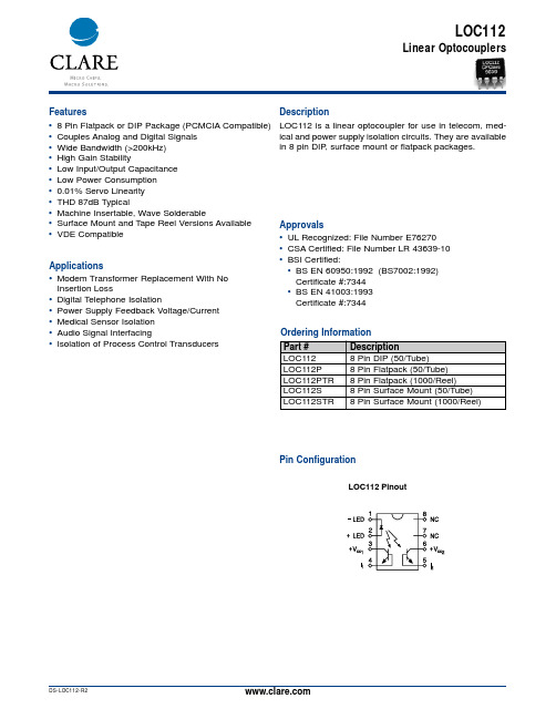
LOC112Linear OptocouplersApplicationsFeaturesDescriptionApprovalsOrdering Information Pin ConfigurationLOC112 is a linear optocoupler for use in telecom, med-ical and power supply isolation circuits. They are available in 8 pin DIP , surface mount or flatpack packages.•Modem Transformer Replacement With No Insertion Loss•Digital Telephone Isolation•Power Supply Feedback Voltage/Current •Medical Sensor Isolation •Audio Signal Interfacing•Isolation of Process Control Transducers•UL Recognized: File Number E76270•CSA Certified: File Number LR 43639-10•BSI Certified:•BS EN 60950:1992 (BS7002:1992)Certificate #:7344 •BS EN 41003:1993Certificate #:7344•8 Pin Flatpack or DIP Package (PCMCIA Compatible)•Couples Analog and Digital Signals •Wide Bandwidth (>200kHz)•High Gain Stability•Low Input/Output Capacitance •Low Power Consumption •0.01% Servo Linearity •THD 87dB Typical•Machine Insertable, Wave Solderable•Surface Mount and Tape Reel Versions Available •VDE CompatibleLOC112 PinoutÐLED +LED +V cc 1I1NC NC +V cc 2I 2LOC112Absolute Maximum Ratings are stress ratings. Functionaloperation of the device at these or any other conditionsbeyond those indicated in the operational sections of thisdata sheet is not implied. Exposure of the device to theabsolute maximum ratings for an extended period maydegrade the device and effect its reliability.Absolute Maximum Ratings (@ 25o C)Electrical Characteristics1 LOC111 and LOC112 Bins D,E,F,G.2Derate Linearly 6.67 mW/°CK3 Sorted BinsBin A= 0.550-0.605 Bin B= 0.606-0.667 Bin C= 0.668-0.732 Bin D= 0.733-0.805 Bin E= 0.806-0.886 Bin F= 0.887-0.974 Bin G= 0.975-1.072 Bin H= 1.073-1.179 Bin I= 1.180-1.297 Bin J= 1.298-1.426•The LOC110/LOC111/LOC112 are shipped in anti-static tubes of 50 pieces. Each tube will contain one K3 sorted bin.•Bin designation marked on each device (A-J).•Orders for the LOC110 product will be shipped using bins available at the date of the order. Any bin (A-J) can be shipped.•For customers requiring selected bins D E F G we offer part num-bers LOC111 or LOC112.LOC112Performance Data*The Performance data shown in the graphs above is typical of device performance. For guaranteed parameters not indicated in the written specifications, please contact our application department.LOC112Dimensionsmm (inches)Mechanical DimensionsCPC7581 Mechanical DimensionsDimensionsmm(inches)CLARE LOCATIONSClare Headquarters78 Cherry Hill DriveBeverly, MA01915Tel: 1-978-524-6700Fax: 1-978-524-4900Toll Free: 1-800-27-CLARE Clare Micronix Division145 ColumbiaAliso Viejo, CA92656-1490 Tel: 1-949-831-4622Fax: 1-949-831-4628SALES OFFICES AMERICASAmericas HeadquartersClare78 Cherry Hill DriveBeverly, MA01915Tel: 1-978-524-6700Fax: 1-978-524-4900Toll Free: 1-800-27-CLARE Eastern RegionClareP.O. Box 856Mahwah, NJ 07430Tel: 1-201-236-0101Fax: 1-201-236-8685Toll Free: 1-800-27-CLARE Central RegionClare Canada Ltd.3425 Harvester Road, Suite 202 Burlington, Ontario L7N 3N1 Tel: 1-905-333-9066Fax: 1-905-333-1824Western RegionClare1852 West 11th Street, #348 Tracy, CA95376Tel: 1-209-832-4367Fax: 1-209-832-4732Toll Free: 1-800-27-CLARE CanadaClare Canada Ltd.3425 Harvester Road, Suite 202 Burlington, Ontario L7N 3N1 Tel: 1-905-333-9066Fax: 1-905-333-1824EUROPEEuropean HeadquartersCP Clare nvBampslaan 17B-3500 Hasselt (Belgium)Tel: 32-11-300868Fax: 32-11-300890FranceClare France SalesLead Rep99 route de Versailles91160 ChamplanFranceTel: 33 1 69 79 93 50Fax: 33 1 69 79 93 59GermanyClare Germany SalesActiveComp Electronic GmbHMitterstrasse 1285077 ManchingGermanyTel: 49 8459 3214 10Fax: 49 8459 3214 29ItalyC.L.A.R.E.s.a.s.Via C. Colombo 10/AI-20066 Melzo (Milano)Tel: 39-02-95737160Fax: 39-02-95738829SwedenClare SalesComptronic ABBox 167S-16329 SpångaTel: 46-862-10370Fax: 46-862-10371United KingdomClare UK SalesMarco Polo HouseCook WayBindon RoadTauntonUK-Somerset TA2 6BGTel: 44-1-823 352541Fax: 44-1-823 352797ASIA PACIFICAsian HeadquartersClareRoom N1016, Chia-Hsin, Bldg II,10F, No. 96, Sec. 2Chung Shan North RoadTaipei, Taiwan R.O.C.Tel: 886-2-2523-6368Fax: 886-2-2523-6369Worldwide Sales OfficesSpecification: DS-LOC112-R2©Copyright 2001, Clare, Inc.All rights reserved. Printed in USA.02/23/01Clare cannot assume responsibility for use of any circuitry otherthan circuitry entirely embodied in this Clare product. No circuitpatent licenses nor indemnity are expressed or implied. Clarereserves the right to change the specification and circuitry, with-out notice at any time. The products described in this documentare not intended for use in medical implantation or other direct lifesupport applications where malfunction may result in direct phys-ical harm, injury or death to a person.。
STS2011中文使用说明书

第一章简介§1.1 软件简介SuperTestSystem2011是一款试验机通用测控软件【下面简称STS2011软件】,该软件前身是电液伺服万能试验机测控软件(即WAW系列软件)。
STS2011不是WAW 系列软件基础上的完善升级,而是再全新设计理念及软件框架下重新研发新软件。
STS2011软件具有先进的设计理念,STS2011基于多核多线程处理器对线程进行序列化设计,更加合理利地应用了多核计算机系统资源优势。
STS2011软件可以适用于多种类型的试验机,例如数显式试验机、屏显式试验机、电液伺服万能试验机、电液伺服压力试验机、电子万能试验机、卧式拉力试验机、弯曲试验机等对各种材料进行拉伸、压缩、弯曲等各种试验。
软件可支持任意的测控卡、控制器系统【需驱动支持】。
STS2011具有二次开发平台,并提供示例源代码支持二次开发应用。
STS2011软件具有超前的开放性、强大的兼容性,同时还延续了早期版本的稳定性、可靠性,操作简单,界面友好。
§1.2 主要功能特点描述该测控软件用于试验机进行各种金属及非金属的试验,按照相应标准完成实时测量与显示、实时控制及数据处理、结果输出等各种功能。
主要功能、特点描述总结如下:(1)人性化的软件界面设计,让界面活起来。
具有切换界面皮肤功能,多种界面风格可选,可根据不同的审美观选择自己喜欢的风格,高级用户还可自行设计个性化的风格;(2)基于多核多线程处理器对线程进行序列化设计,更加合理利用多核计算机系统资源优势。
在硬件支持的条件下,在Windows操作系统下采样周期及控制周期均可突破毫秒级限制。
(3)特色并发执行。
可实现试验控制操作、试样信息输入、数据分析同步并发执行,互不干扰,试验中即可以进行数据处理和试样信息的添加修改,并可以试验中打开以前试验数据进行分析比对操作。
(4)特色的试验过程分析模式。
试验过程中即可随时分析该次试验采集的试验数据。
试验过程中可以进行数据处理分析打印。
MX23A34SF1;MX23A26SF1;MX23A36SF1;MX23A18SF1;MX23A12SF1;中文规格书,Datasheet资料

•Insulation resistance: 100M ohm min. •Life time: 50 times •Applicable wire : Position of using wire is specified. Cable type Conductive area A.W.G No. Sheath diameter AVSS, AVS(partially) 0.3 to 1.25mm2 #22 to #16 1.6dia. to 2.2dia. mm
Part Number MX23A12SF1 MX23A12XF1 MX23A12NF1 MX23A18SF1 MX23A18XF1 MX23A18NF1 MX23A18NF2 MX23A26SF1 MX23A26XF1 MX23A26NF1 MX23A26NF2 MX23A34SF1 MX23A34XF1 MX23A34NF1 MX23A34NF2 M23S05K351 M120-55780
■Socket Contact Materials/Finishes Copper alloy/Sn plating
Rear cover Grommet Socket housing
Seal ring Front cap
Pin insulator
Pin contact
Crimp tool
Hand crimping tool CT160-3B-MX23 Semi automatic applicator 350-MX23-2 Contact release jig ET-MX23
mx23a34sf1;mx23a26sf1;mx23a36sf1;mx23a18sf1;mx23a12sf1;中文规格书,datasheet资料 componentsproduct information connector new 1/7 mb-0094-2 june 2006 jae pmk div. proprietary. copyright 2006,japanaviation electronics industry, ltd. features general specifications mx23a series compact type low-profiled waterproof connector contacts:12 ,18, 26, 34 pos. (pin side 2types: reverse standard**excluding 12 pos.) contact resistance: 10m ohm max.?dielectric withstanding voltage: ac 1000 vr.m.s minute)?operating temperature: -40 to+125 deg. (includingtemperature rise caused powerdistribution)?current rating: 3a?insulation resistance: 100m ohm min.?life time: 50 times?applicable wire usingwire specified.low profiled type boardmounting height socketconnector height 22.2mmmax. double fin structure highreliability socketcontact largechamfer front-edgeside preventgrommet from damaging. incomplete insertion socketcontact itshousing can frontcap mounting process. full water poof grommet socketcontact crimping area reducesize. water pro
道尔斯特电气产品说明书

南京道尔斯特电气有限公司地址:南京市秦淮区中山东路448号普华大厦4层QQ :2148984411 网址:回 传我希望了解道尔斯特电气的以下产品我希望了解更多的信息关于:姓名:公司:部门:地址/邮政编码:电话号码/传真:电子邮件:样本工业防雷PDU系列样本数显表/液晶表系列样本温湿度控制系列样本智能隔离器/安全栅系列工业交换机选型手册Product Catalog2022.1版精益求精KEEP IMPROVING样本工业交换机系列样本超级电容缓冲装置系列百兆工业级光电转换器支持2个百兆电口、1个百兆光口光口SC/ST/FC 可选,距离可选可选24V/220V 电源输入工业IP40防护等级支持导轨式/壁挂式安装● ●●●●产品简介DST-MC-3系列工业级百兆光电转换器,支持百兆电口到百兆光口的转换。
冗余电源设计,宽电压范围输入,并提供过载和反接保护。
强抗电磁干扰能力,完全满足苛刻的工业应用环境。
交换机参数IEEE 标准IEEE 802.310BaseT EthernetIEEE 802.3u 100BaseT(X) and 100BaseFX Fast Ethernet IEEE 802.3x Flow Control(流量控制)交换特性MAC 地址表2K 数据包缓存1Mbit 处理方式存储转发接口RJ45端口数2个百兆电口百兆光口1个百兆光口,单模/多模可选,SC/ST/FC 可选,单纤/双纤可选百兆光口传输距离多模2km,单模20km/40km/60km/120km 可选LED 指示灯电源、电口、光口电源24V 输入4针端子,双电源;24VDC 电源支持范围为12~36VDC 220V 输入4针端子,单电源;220V 电源支持范围为85~264VAC/77~300VDC 电源功耗最大3瓦电源保护反接保护、过载保护环境属性工作温度-40~75°C 储存温度-40~85°C相对湿度5~95% (无凝霜)物理特性外壳IP40金属外壳安装方式默认导轨安装,可选壁挂安装尺寸30(W) x 125(H) x 88(D) mm认证EMIFCC Part 15. CISPR(EN55022) class A EMSEN 61000-4-2(ESD)Level 3EN 61000-4-3(RS)Level 3EN 61000-4-4(EFT)Level 3EN 61000-4-5(Surge)Level 3EN 61000-4-6(CS)Level 3EN 61000-4-8机械IEC60068-2-6(震动) IEC60068-2-27(冲击) IEC60068-2-32(自由跌落)质保期MTBF 380000h 保修期5年0102配置型号产品描述DST-MC-2TX/1MC 百兆工业级光电转换器,2个百兆电口,1个百兆SC 光口,多模双纤2公里,24V 双电源DST-MC-2TX/1SC百兆工业级光电转换器,2个百兆电口,1个百兆SC 光口,单模双纤20公里,24V 双电源配置型号产品描述机架插卡式光电转换器每个机箱支持16个卡槽,板卡支持1个电口、1个光口百兆板卡或者千兆板卡可混插机箱双电源供电● 产品简介DST-MC-16系列机架插卡式光电转换器,标准2U 机箱,共支持16个插槽。
MS4120F、MS4620F、MS8120F、S2024-F和S20230-F快速作用双位置驱动器

PRODUCT DATAPut Bar Code Here63-2584-10MS4120F; MS4620F; MS8120F; S2024-F; S20230-F Fast-Acting, Two-Position ActuatorsAPPLICATIONThe MS4120F , MS4620F , MS8120F , S2024-F , and S20230-F Fast-Acting, T wo-Position Actuators are spring return direct coupled actuators (DCA) for on/off damper control. The actuator accepts an on/off signal from a single-pole, single-throw (spst) controller. Reversible mounting allows actuator to be used for either clockwise (cw) or counterclockwise (ccw) spring rotation.Designed to operate reliably in smoke control systemsrequiring Underwriter’s Laboratories Inc. UL555S ratings up to 350°F .APPLICABLE LITERATURE—Specification Data Sheet63-2592—Motor/Actuator Selection Guide for Damper Applications63-8419—Engineering Manual of Automatic Control (also called The Gray Manual)77-1100—Direct Coupled Actuator Quick Selection Guide 63-8553—Damper T orque Calculator63-8437FEATURES•175 lb-in. (20 Nm) minimum driving torque at 350°F (176°C).•Reversible mounting facilitates use in either clockwise (cw) or counterclockwise (ccw) spring rotation.•Integral spring return ensures level of return torque.•Stainless steel internal spring.•Fifteen-second spring return timing.•No special cycling required during long-term holding. (See Operation section.)•No audible noise during holding.•Patent pending design eliminates need for limit switches to reduce power consumption.•Models available for 24, 120, and 230 Vac applications.•Ninety-five degree angle of rotation.•Actuator holds rated torque at reduced power level.•Die-cast aluminum housing.•Housing design allows flush mounting to damper.•Self-centering shaft adapter (SCSA), patent pending.•Designed to operate reliably in smoke control systems requiring Underwriter’s Laboratories Inc. UL555S ratings up to 350°F.MS4120F, MS4620F, MS8120F•High temperature Teflon ® lead wires.•Models available with integral high temperature (350°F) SPST position-indicating switches (7°, 85° stroke).S2024-F, S20230-F•Double-insulation rating.•High-temperature, halogen-free, silicone-free leadwires.•Models available with integral high temperature (350°F)SPDT position-indicating switches (7°, 85° stroke).MS4120F; MS4620F; MS8120F; S2024-F; S20230-F FAST-ACTING, TWO-POSITION ACTUATORS63-2584—102SPECIFICATIONSModels: See Tables 1, 2, and 3.Table 1. Models.aInternal switches are designed to pass UL555Srequirements (at 350°F).Dimensions: See Fig. 1.Device Weight:MS4120F , MS4620F , S20230-F: 7.5 lb (3.4 kg)MS8120F , S2024-F: 6.25 lb (2.8 kg)Stroke: 95° ± 3°, mechanically limited.Electrical Ratings:Power Input:MS4120F: 120 Vac ±10%, 60 Hz.MS4620F ,S; S20230-F: 230 Vac ±10%, 50/60 Hz.MS8120F ,S; S2024-F: 24 Vac +20%, -10%, 50/60 Hz (Class 2).Power Consumption:MS4120F: Driving: 0.35A, 35W. Holding: 0.15A, 10W.MS4620F ,S; S20230-F:Driving: 0.20A, 35W. Holding: 0.14A, 10W.MS8120F ,S; S2024-F: Driving: 45 VA. Holding: 10 VA.Electrical Connections:Lead Wires:MS4120F , MS4620F , MS8120F: 1m T eflon wire.MS4620S, MS8120S, S2024-F , S20230-F: 1m halogen-free, silicone-free wire.T wo integral 3/8 in. flexible conduit connections.Timing (At Rated Torque and Voltage):Drive Open: 15 seconds typical.Spring Close: 15 seconds typical.Auxiliary Switches:Dry ContactRatings (maximum load): 250 Vac, 5A resistive.Settings (fixed): 7° nominal stroke, 85° nominal stroke.Torque Rating (at Rated Voltage):T ypical Holding (minimum at 350°F): 175 lb-in. (20 Nm).Spring Return (minimum at 350°F): 175 lb-in. (20 Nm).Stall Maximum (fully open at 75°F): 425 lb-in. (48.0 Nm).350°F Minimum Driving: 175 lb-in. (20 Nm).Design Life (at Rated Voltage): 30,000 full stroke cycles.Minimum Damper Shaft Length:1 in. (25 mm); 3-1/4 (83 mm) recommended.Cycling Requirements:Prolonged holding-period (1 year) testing of these actuators has been performed with no spring return failures. The actuator and the internal spring are designed to require no special cycling during long-term holding.Honeywell recommends following all local, state and national codes for periodic testing of the entire smoke control system. Refer to National Fire Protection Association (NFP A) National Fire Codes®: NFP A90A, NFP A92A and NFP A92B for your application.NFP A recommends periodic examination of each fire/smoke damper (semi-annually or annually) to ensure proper performance.Mounting: Self-centering shaft adapter.Round Damper Shafts: 0.5 to 1.06 in.Square Damper Shafts: 1/2 to 3/4 in.Actuator can be mounted with shaft in any position.IMPORTANT•Honeywell does not recommend using linkages with these actuators because side-loading of the output hub reduces actuator life.•3/4 in. or greater shaft diameter recommended.Noise Rating at 1m (Maximum):Driving or Spring Return: 70 dBA.Holding: 20 dBA (no audible noise).Vibration:Not suitable for high vibration applications (Example installa-tion environment: T ruck Trailers or Railroad Cars)Acceptable Vibration Levels 0.6g at 30 to 300 Hz.Temperature Ratings:Ambient: -40°F to 130°F (-40°C to 55°C).Shipping and Storage: -40°F to 140°F (-40°C to 60°C).IMPORTANTThe actuator is designed to meet UL555S standards at 350°F (176°C). The actuator must be tested with the damper to achieve this rating.NOTE:The actuator is designed to operate for 30 min-utes during a one-time excursion to 350°F (176°C).Humidity Ratings: 5% to 95% RH noncondensing.Environmental Protection Ratings:NEMA2 and IP54 when mounted on a horizontal shaft and the base of the actuator below the shaft.Accessories:205649 Mounting Bracket (not supplied with actuator).Approvals: See Table 4.Controller Type:MS4120F: Line voltage (120 Vac), 2-position, spst (Series 40).MS4620F ,S; S20230-F: Line voltage (230 Vac), 2-position, spst (Series 40).MS8120F ,S; S2024-F: Low voltage (24 Vac), 2-position, spst (Series 80).ModelVoltage in Vac Internal Auxiliary Switches MS4120F1006120None MS4120F1204120 2 SPST a MS4620F1005230None MS4620F1203230 2 SPST a MS8120F100224None MS8120F120024 2 SPST a S2024-F (MS8120S1006)24NoneS20230-F (MS4620S1009)230S2024-F-SW2 (MS8120S1204)242 SPDT a S20230-F-SW2 (MS4620S1207)230MS4120F; MS4620F; MS8120F; S2024-F; S20230-F FAST-ACTING, TWO-POSITION ACTUATORS363-2584—10Table 4. Approvals.a Plenum applications require that conductors be enclosed inconduit (see Wiring section for conduit details).Fig. 1. Dimensional drawing of actuator in in. (mm).Table 2. Actuator Selection (MS Series)M Electrical MotorS Fail Safe Function (Spring Return)41120 Vac 2-position Control; Reversible MountSpring Return 46230 Vac 2-position Control; Reversible MountSpring Return 8124 Vac 2-position Control; Reversible MountSpring Return20175 lb-in. (20 Nm)F Fire and Smoke (US)1No Feedback0No Auxiliary Switches 2T wo Auxiliary SwitchesXX System Controlled NumbersM S 4120F 12XXTable 3. Actuator Selection (S20 Series).S Fail Safe Function (Spring Return)2020 Nm (175 lb-in.)2424 Vac 2-position Control; Reversible Mount Spring Return230230 Vac 2-position Control; Reversible MountSpring ReturnF Fire and Smoke ActuatorNo Auxiliary Switches-SW2T wo Auxiliary SwitchesS 2024-F -SW2MS4120F MS4620F,MS8120F S20230-FS2024FUL/cULXX UL873 Plenum Rating, File No. E4436; Guide No. XAPX.a X XCE X X C-TICKXXXMS4120F; MS4620F; MS8120F; S2024-F; S20230-F FAST-ACTING, TWO-POSITION ACTUATORS63-2584—104INSTALLATIONWhen Installing this Product...1.Read these instructions carefully. Failure to followthem could damage the product or cause a hazardous condition.2.Check the ratings given in the instructions and on the product to make sure the product is suitable for your application.3.Installer must be a trained, experienced service technician.4.After installation is complete, check out product operation as provided in these instructions.WARNINGElectrical Power Hazard.Line voltage can cause death or serious injury and short equipment circuitry.Disconnect power supply before installation.Low voltage can shock individuals or short equipment circuitry.Disconnect power supply before installation.IMPORTANTAll wiring must agree with applicable codes, ordinances and regulations.Locationsecures it flush to a damper box (see Fig. 2).NOTE:When mounted correctly, these slots allow theactuator to float without rotating relative to the damper shaft.Tightly securing actuator to damper housing can damage actuator.Mount actuator to allow it to float along its vertical axis.PreparationBefore mounting the actuator onto the damper shaft, determine the:—Damper/valve opening direction for correct spring return rotation. The actuator can be mounted to provide clockwise or counterclockwise spring return.—Damper shaft size (see Specifications section).Determine Appropriate Mounting OrientationSee Fig. 2 for mounting orientation.NOTES:—Actuators are shipped in the fully closed position.—An arrow molded into the hub points to tick marks on the label to indicate the hub rotary position.—See Fig. 3 for proper mounting to a square damper shaft.Fig. 2. Spring Return DCA mounting orientation.Fig. 3. Proper mounting to square damper shaft.Measure Damper/Valve Shaft LengthIf the shaft is less than three inches in length, the shaft coupling must be located between the damper/valve andactuator housing. If the shaft length is more than three inches, the shaft coupling may be located on either side of the actuator housing.If the coupling must be moved from one side of the actuator to the reverse, follow these instructions (see Fig. 4):1.Remove the retainer clip from the shaft coupling and setit aside for later use.2.Remove shaft coupling from one side of the actuator.3.Replace the shaft coupling on the opposite side of theactuator aligning it based on the stroke labelling.4.Replace the retainer clip on the shaft coupling using thegroove of the coupling.MS4120F; MS4620F; MS8120F; S2024-F; S20230-F FAST-ACTING, TWO-POSITION ACTUATORS563-2584—10Fig. 4. Mounting shaft coupling to actuator opposite side.MountingImproper shaft coupling tightening causes device malfunction.Tighten shaft coupling with proper torque to preventdamper shaft slippage.Using actuator as shaft bearing causes device damage.Use actuator only to supply rotational torque. Avoid any side loads to actuator output coupling bearings.T o mount actuator, proceed as follows:1.Place actuator over damper shaft; and hold mountingbracket in place. See Fig. 5.2.Mark screw holes on damper housing.3.Remove actuator and mounting bracket.4.Drill or center-punch holes for mounting screws (or useno.10 self-tapping sheet metal screws).NOTE:If necessary, use a field-fabricated steel baseplate secured with sheet metal screws.5.Turn damper blades to desired normal (closed) position.6.Place actuator and mounting bracket back into position and secure bracket to damper box with sheet metal screws.7.Using 10mm wrench, tighten shaft coupling securely onto damper shaft using minimum 120 lb-in., maximum 180lb-in. torque.Fig. 5. Mounting actuator to damper housing.MS4120F; MS4620F; MS8120F; S2024-F; S20230-F FAST-ACTING, TWO-POSITION ACTUATORS63-2584—106Manual PositioningThe actuator can be operated with no power present. Use this feature during installation or to move and lock the damper or valve shaft position when there is no power.T o operate the manual positioning:1.If the power is on, turn it off.2.Insert supplied hex wrench (key) as shown in Fig. 6.3.Rotate key in the direction indicated on the cover.4.Once the desired position is reached, hold the key toprevent the spring return from moving the actuator.NOTE:No detente for fire and smoke actuators. If keyis released, actuator will return to spring closed position.Fig. 6. Manual positioning.WIRINGSee Fig. 7 through 11 for typical wiring diagrams.WARNINGElectrical Power Hazard.Line voltage can cause death or serious injury and short equipment circuitry.Disconnect power supply before installation.Disconnect all power supplies before installation.Motors with auxiliary switches can have more than one disconnect.IMPORTANT1.All wiring must comply with local electrical codes, ordinances and regulations.2.Voltage and frequency of transformer used with MS8120F ,S and S2024-F must correspond with the characteristics of power supply and actuator.NOTE:The conduit fittings are designed for use with 3/8in. reduced-wall steel or aluminum flexible con-duit.Fig. 7. Typical 24 Vac wiring (MS Series).Fig. 8. Typical 120 Vac wiring (MS Series).Fig. 9. Typical 230 Vac wiring (MS Series).MS4120F; MS4620F; MS8120F; S2024-F; S20230-F FAST-ACTING, TWO-POSITION ACTUATORS763-2584—10Fig. 10. Typical 24 Vac wiring (S20 Series).Fig. 11. Typical 230 Vac wiring (S20 Series).MS4120F; MS4620F; MS8120F; S2024-F; S20230-F FAST-ACTING, TWO-POSITION ACTUATORS63-2584—108OPERATIONThe actuators are designed for use in Smoke ControlSystems. If power fails, the actuator spring returns to the 0° position. The actuator mounts flush with the damper box. The actuator drives from 0° to 95° and spring returns back to 0°.The actuators are operated by an spst two-position controller. When using an spst two-position controller, the actuator drives to the damper fully open position when controller contact makes and spring returns to the damper fully closed position when controller contact breaks. The actuator drops to holding power level on detection of stall, independent of hub position.CyclingThe actuator and the internal spring are designed so that no special cycling during long-term holding is required.Honeywell recommends following all local, state, and national codes for periodic testing of the entire smoke control system. Refer to National Fire Protection Association (NFP A) National Fire Codes ®: NFP A90A, NFP A92A, and NFP A92B for your application.Auxiliary SwitchesSome models include auxiliary switches (see Table 1).SPST Switches (Table 5)See Fig. 7 through 9 for SPST auxiliary switch wiring.Table 5. SPST Auxiliary Switch Operation.NOTE:Both sets of contacts are open when the actuatoris between 7° and 85°.SPDT Switches (Fig. 12)See Fig. 10 through 12 for SPDT auxiliary switch wiring.Fig. 12. SPDT auxiliary switch operation.CHECKOUTMS4120F (120 Vac model)1.Check damper position.2.Connect 120 Vac to the black and white leadwires to drive the damper to the open position. The actuator should drive the damper.3.If the actuator does not run, remove power for at least two seconds.4.If the actuator spring returns, allow it to close entirely, then return to step 2.5.If the actuator does not spring return, verify that the actuator is properly installed. See Installation section.6.If the actuator is correctly installed but neither runs nor spring returns, replace the actuator.MS4620F; S20230-F (230 Vac models)1.Check damper position.2.Connect 230 Vac to the blue and brown leadwires to drive the damper to the open position. The actuator should drive the damper.3.If the actuator does not run, remove power for at least two seconds.4.If the actuator spring returns, allow it to close entirely, then return to step 2.5.If the actuator does not spring return, verify that the actuator is properly installed. See Installation section.6.If the actuator is correctly installed but neither runs nor spring returns, replace the actuator.MS8120F; S2024-F (24 Vac models)1.Check damper position.2.Connect 24 Vac to the red and black leadwires to drive the damper to the open position. The actuator should drive the damper.3.If the actuator does not run, remove power for at least two seconds.4.If the actuator spring returns, allow it to close entirely, then return to step 2.5.If the actuator does not spring return, verify that the actuator is properly installed. See Installation section.6.If the actuator is correctly installed but neither runs nor spring returns, replace the actuator.Switch Wire Color MakesBreaks (degrees from fully closed position)7°blue less than 7greater than 785°yellowgreater than 85less than 85MS4120F; MS4620F; MS8120F; S2024-F; S20230-F FAST-ACTING, TWO-POSITION ACTUATORSD Montageanweisung NL Installatievoorschrift SF AsennusohjeF Instructions d’Installation DK Installasjonsinstruks S Installations InstrukionerI Istruzioni per I’Installazione N Installationsinstrukioner E Instrucciones de montage963-2584—10MS4120F; MS4620F; MS8120F; S2024-F; S20230-F FAST-ACTING, TWO-POSITION ACTUATORS63-2584—1010MS4120F; MS4620F; MS8120F; S2024-F; S20230-F FAST-ACTING, TWO-POSITION ACTUATORS1163-2584—10MS4120F; MS4620F; MS8120F; S2024-F; S20230-F FAST-ACTING, TWO-POSITION ACTUATORSAutomation and Control SolutionsHoneywell International Inc.1985 Douglas Drive North Golden Valley, MN 55422 ® U.S. Registered T rademark© 2012 Honeywell International Inc. 63-2584—10 M.S. Rev. 03-12 Printed in United StatesT eflon® is a registered trademark of the E.I. du Pont de Nemours and Company.National Fire Codes® is a registered trademark of the National Fire Protection Association (NFP A).。
2008年Ford自动变速箱组件目录说明书

1622008 AUTOMATIC TRANSMISSION KIT & COMPONENTS CATALOG ©2008 PARKER HANNIFIN CORP. ALL RIGHTS RESERVED3790103008397797405R55N / 5R55S / 5R55WRWD 5 SpeedA544510034070670Input ShaftO.Dr. Ring GearO.Dr. CenterShaft783Center SupportInterm. BandDirect DrumForward ClutchForward PlanetReverse BandReverse DrumLow Sprag310037179520036178530311914363912911913910896904896437490996V.B.Parts741E414494765-6370Case313321320Valve Body917747765746322420002OHK Kit004Master L/Steels Kit 006Master 030External Seal Kit1632008 AUTOMATIC TRANSMISSION KIT & COMPONENTS CATALOG ©2008 PARKER HANNIFIN CORP . ALL RIGHTS RESERVEDRWD 5 Speed5R55N / 5R55S / 5R55W862981971961560961971985879565126106146861*229964974877564285872962972104124552894Intermediate Sprag690074266Park Gear264847Park Pawl Assy995-1995-2995-3995916-2916-3919922915916-2916-3919922916263EDA181554770Ext. Hsg.781493305678Output ShaftO.Dr. Band StrutInterm. Band Strut268841Internal Linkage991-2991-3994799991-4761P-4991072410992Yoke1642008 AUTOMATIC TRANSMISSION KIT & COMPONENTS CATALOG©2008 PARKER HANNIFIN CORP. ALL RIGHTS RESERVED*Prefix Letter ‘T’ denotes Toledo-Trans Kit (TTK) Brand Transmission Kits *Prefix Letter ‘B’ denotes Bryco Brand Transmission Kits002.............T16002AP......Overhaul Kit, 5R55N (With Bonded Pistons) 1999-Up ..............................................................1..........002.............T16002GP......Overhaul Kit, 5R55S/5R55W (With Bonded Pistons) 2002-Up..................................................1..........004.............T16004AP......Master L/Steels Kit, 5R55N (With Bonded Pistons) 1999-Up ....................................................1..........004.............T16004GP......Master L/Steels Kit, 5R55S/5R55W (With Bonded Pistons) 2002-Up .......................................1..........006.............T16006AP......Master W/Steels Kit, 5R55N (With Bonded Pistons) 1999-Up...................................................1..........006.............T16006GP......Master W/Steels Kit, 5R55S/5R55W (With Bonded Pistons) 2002-Up ......................................1..........E300...........45019............Gasket, 5R55N Bottom Pan (Plastic With Silicon Bead) OE Style (With Large Holes) 1999-Up 1..........XW4Z-7A191CA D305...........45097668......Gasket, 5R55N/5R55S/5R55W Extension Housing To Case 1999-Up......................................1..........XW4Z-7086-AA A309..........41217............Gasket, 5R55N/5R55S/5R55W Pump Bolt Washer...................................................................AR ........A310..........45097667......Gasket, 5R55N/5R55S/5R55W Pump 1999-Up..........................................................................1..........XW4Z-7A136AB A311...........1988096........O-Ring, 5R55N/5R55S/5R55W Pump Cover 1999-Up ...............................................................1..........XW4Z-7A248AA A313..........1994747........O-Ring, 5R55N Inner Pump Gear 1999-Up.................................................................................1..........F77Z-7L323AA E320...........45097692......Gasket, 5R55N Valve Body Separator Plate To Case 1999-Up ................................................1..........XW4Z-7D100-BF E320...........45097738......Gasket, 5R55S/5R55W Valve Body Separator Plate To Case (Upper) 2002-Up......................1..........1L2Z-7Z490AB-1A070..........70243V..........Seal, 5R55N/5R55S/5R55W Front (No Flange) (Rubber Coated) 1999-Up ..............................1..........F77Z-7A248AA D072...........70083............Seal, 5R55N Linkage 1999-Up ..................................................................................................1..........D5AZ-7B498A D074...........70283............Seal, 5R55N Rear 2WD 2000-Up ...............................................................................................1..........XW4Z-7052AA D074...........70205............Seal, 5R55S/5R55W Rear (W/Long Boot) 2WD 2002-Up .........................................................1..........F6UZ-7052A D074...........70282............Seal, 5R55S/5R55W Extension Housing 4X4 2002-Up .............................................................1..........1L2Z-7052BA175.............6358..............Ring Kit, 5R55N/5R55S/5R55W (2 Metal 4PTFE 2 Torlon Rings) 1999-Up ...............................1..........A178..........45060279......Ring, 5R55N, 5R55W, 5R55S Pump Support (Lock-Up) 1999-Up .............................................1..........B181...........TAW- 2212....Ring, 5R55N, 5R55W, 5R55S Forward Clutch Cylinder 1999-Up .............................................2..........D184...........45060265......Ring, 5R55N, 5R55W, 5R55S Output Shaft 1999-Up.................................................................1..........A179..........30308............Ring, 5R55N, 5R55W, 5R55S Overdrive Brake Drum 1999-Up.................................................2..........B179...........30308P ..........Ring, 5R55N, 5R55W, 5R55S Direct Clutch (Center Support) 1999-Up Torlon .........................2..........119.............45082NR........Friction Module, 5R55N 1999-Up................................................................................................1..........119.............45082LR........Friction Module, 5R55S/5R55W 2002-Up...................................................................................1..........E010...........45040N ..........Filter, 5R55N (3/8” Tall Pick-up Tube) 1999-Up ..........................................................................1..........XW4Z-7A098BB E010...........F-340.............Filter, 5R55S/5R55W (2 1/4” Tall Pick-Up Tube) 2002-Up..........................................................1..........1L2Z-7A098AC5R55N / 5R55S / 5R55WRWD 5 Speed1652008 AUTOMATIC TRANSMISSION KIT & COMPONENTS CATALOG ©2008 PARKER HANNIFIN CORP. ALL RIGHTS RESERVEDB022...........45090............Band, 5R55N Overdrive/Intermediate (Hi-Energy) 1999-Up......................................................2..........XW4Z-7D034BA 030.............45030G..........Bushing Kit, 5R55N/5R55S/5R55W 1999-Up.............................................................................1..........A034..........31530............Bushing, 5R55N/5R55S/5R55W Pump Cover 1999-Up .............................................................1..........A036..........31531............Bushing, 5R55N/5R55S/5R55W Overdrive Sun Gear 1999-Up................................................1..........A036..........45039............Bushing, 5R55N/5R55S/5R55W Stator (Front) 1999-Up ...........................................................1..........A037..........31532............Bushing, 5R55N/5R55S/5R55W Stator (Rear) 1999-Up............................................................1..........A046..........31533............Bushing, 5R55N/5R55S/5R55W Coast Clutch Drum e 56036A................................................................................................................................1..........B211...........45176A..........Washer, 5R55N/5R55S/5R55W Pump To Coast Clutch Drum .063" (Plastic) 1999-Up.............1..........F7TZ-7D014TA B211...........45176B ..........Washer, 5R55N/5R55S/5R55W Pump To Coast Clutch Drum .071" (Plastic) 1999-Up.............1..........F7TZ-7D014MA B211...........45176C ..........Washer, 5R55N/5R55S/5R55W Pump To Coast Clutch Drum .075" (Plastic) 1999-Up.............1..........F7TZ-7D014NA B211...........45176D ..........Washer, 5R55N/5R55S/5R55W Pump To Coast Clutch Drum .079" (Plastic) 1999-Up.............1..........F7TZ-7D014PA B211...........45176E ..........Washer, 5R55N/5R55S/5R55W Pump To Coast Clutch Drum .083" (Plastic) 1999-Up.............1..........F7TZ-7D014RA B211...........45176F ..........Washer, 5R55N/5R55S/5R55W Pump To Coast Clutch Drum .087" (Plastic) 1999-Up.............1..........F7TZ-7D014SA C232...........45145............Washer, 5R55N/5R55S/5R55W Bearing to Forward Hub (Solid Bronze) 1999-Up .................1..........FOTZ-7D090A D263...........45077............Washer, 5R55N/5R55S/5R55W Parking Gear To Case 1999-Up ..............................................1..........D4ZZ-7B368-AD410...........D56955J ........Switch, 5R55N Neutral Safety (12 Prong Connector) 1999-Up ...............................................1..........XW4Z-7F293AA E922...........33991............Nut, 5R55N/S/W Band 1999-Up .................................................................................................2..........380850-SRWD 5 Speed5R55N / 5R55S / 5R55W。
112F1中文资料

H
N4 7 N3 5 N2 3 N1 1 8 6 4 2
8
6
4 3
Par t No.
10.5max.
7
5
1
DATE CODE
TDK
2
ø0.5
Weight: 2g Dimensions in mm
ELECTRICAL CHARACTERISTICS
Part No. 123G∗1E 124H1E 133G1E 134H1E
ET constant (V-µs) min. 25 25 25 15 15 15 12 12 12
Refer to Winding form and pin numberings.
Specifications which provide more details for the proper and safe use of the described product are available upon request. All specifications are subject to change without notice.
KP Series KP-27, -35, -51, -148 Types
SHAPES AND DIMENSIONS
7.3max. 6 4 2 7.1max. 8min. ø0.5 5±0.2
WINDING FORM AND PIN NUMBERINGS
A
N2 5 3 6±0.2 6 4 2
B
N3 5 N2 3 N1 1 6 4 2
KP Series KP-27, -35, -51, -148 Types
SHAPES AND DIMENSIONS
10.5max. 12max. 4±0.6 7.5±0.25
854_伺服液位计-Enraf

浮子材质:AISI 316,重量:223 g,最大压力:2 barg,直径:140 mm 浮子材质:AISI 316,重量:223 g,最大压力:2 barg,直径:110 mm 浮子材质:AISI 316,重量:223 g,最大压力:2 barg,直径:90 mm
多功能测量浮子 —— 测量液位、界面和伺服密度
技术指标 —— 854 ATG
测量指标 量程
液位测量精度 界面测量精度 密度测量精度 温度测量精度 灵敏度 重复性 波动积分时间 最大浮子运动速度 (最大液面跟踪速度) 机械指标 安装法兰 外形尺寸 重量 电缆进口 使用环境 操作压力 环境温度 防护等级 安全性
材料指标 伺服机构腔体部分以及端盖 测量鼓室 外壳表面处理 测量磁鼓及磁鼓轴 测量钢丝 O 型圈 电器性能 电源 频率范围和功率 绝缘电压和雷电保护 通讯类型 通讯类型 通讯协议 电缆 与 PET 通讯 可选择项 报警输出 密度测量 液位模拟量输出 输入板
其他数据通讯类型
:标准 27m :可选 37m,
35m,此时测量钢丝可达 150m :≤ ± 0.4mm :≤ ± 2 mm :≤ ± 3 kg/m3(经过现场标定后 ≤ ± 1 kg/m3) :± 0.1°C :± 0.1mm :± 0.1mm :可在 0.5~10 秒之间 3 点可编程 :40mm/s
通讯电缆和电源电缆
通讯电缆 2 x 1.5mm2 屏蔽双绞通讯电缆(建议采用铠装电缆) 推荐的国产电缆型号:DJYPC3Y32/SA (90) 1x2x1.5,铠装通讯电缆
电源电缆 2 x 1.5mm2 电力电缆 推荐的国产电缆型号:KVV32/SA (90) 2x1.5
型号代码 0815.345 0815.344 0815.343 0815.175 0815.173 0815.171 型号代码 0815.350 0815.355
F107F112F121涡轮风扇发动机

起动点火
系 统 起动和点火同时完成。1个装有固体药柱的点火器,也是起动器。利用固体火药燃烧产生的火焰和燃气进行点火和起动。火焰从起动器喷出后直接进入燃烧室点火,而燃气从起动器喷出直接冲击高压涡轮。火药燃烧时间规定为6s,变化范围为5~9s。
支承系统 低压轴由1、2、5和6号轴承支承。1号是滚珠轴承,放在第1级风扇后面,通过第1级静子叶片传力。2号轴承在低压压气机后面,5号轴承在低压涡轮前面,6号轴承在低压涡轮后端,它们均为滑油润滑的滚棒轴承。高压轴套在低压轴上,由3和4号轴承支承。3号轴承放在前面,是滚珠轴承,放在高压压气机叶轮和附件传动斜齿轮之间。4号轴承在高压涡轮之前。
控制系统 机械液压式。控制起动、加速、减速和稳态转速。
燃油系统 由1个增压和高压泵组件、1个机械液压式计量计算机和1个燃油切断活门组成。根据弹体制导系统来的电压信号调节慢车和最大转速。
滑油系统 完全独立的系统,由1个压力泵、3个回油元件、1个0.615L的滑油箱、1个油滤和燃油-滑油散热器组成。3个回油元件分布在两个涡轮端轴承集油槽内和1个齿轮箱内。
F107-WR-400/402 同F107-WR-101,1976年6月5日首次装于“战斧”上,由A-6A飞机空中发射。
F112-WR-100 它是F107-WR-103的美国空军编号。
F121-WR-100 为威廉斯国际公司目前最小的发动机,用于AGM136空中发射导弹。
F112-WR-100
厂 商 威廉斯国际公司
生产现状 生产
装机对象 F107-WR-100 AGM-86A。
F107-WR-101 AGM-86B。
F107-WR-102 AGM-109。
F107-WR-103 AGM-86C。
福特(Ford)新一代福斯特(Focus)ST性能版车型介绍说明书

N EWS/fordofeurope /FordEuRELEASE AT 09:00 CET ON FEBRUARY 18, 2019All-New Ford Focus ST Blends Track-Day Performance,B-road Fun and Everyday Usability Without Compromise•Ford Performance-developed all-new Focus ST enhanced with advanced sports technologies will go on sale in the summer in five-door and wagon body styles•Powerful, free-revving powertrains include 280 PS, 420 Nm, 2.3-litre EcoBoost petrol with twin-scroll turbo and anti-lag; 190 PS 2.0-litre EcoBlue diesel with 400 Nm from 2,000 rpm•First Ford front-wheel drive electronic limited-slip differential improves traction and stability.Rev-matching offered for short-shift six-speed manual gearbox. Seven-speed auto available •Selectable Drive Modes a first for Focus ST, adjusting features including Electronic Brake Booster and fastest Ford electric power-assisted steering to match performance to scenario •Comfort and driving experience optimised with Recaro sports seats and advanced independent rear suspension configuration with available Continuously Controlled DampingCOLOGNE, Germany, Feb. 18, 2019 – Ford today revealed the all-new Focus ST – developedby Ford Performance to deliver nimble hot-hatchback thrills in a stylish, comfortable andpractical family car.The all-new Focus ST builds on the class-leading driving dynamics of the fourth generationFocus in five-door and wagon body styles. Ford’s new C2 architecture is enhanced with unique suspension, braking and powertrain configurations for the most responsive and agile Focus ST driving experience ever – on road and track.A new engine line-up makes available to drivers up to 12 per cent more power and 17 per centmore torque compared with the previous generation Focus ST. Ford’s 280 PS 2.3-litre EcoBoost petrol and 190 PS 2.0-litre EcoBlue diesel engines* both deliver a broad spread of power andtorque across the rev-range, for fast-revving sports performance.Ford’s first application of an electronic limited-slip differential (eLSD) for a front-wheel drivevehicle further enhances as standard the cornering and stability of the EcoBoost-poweredvariant – sharpening responses to changing grip levels and driver inputs using computer-controlled pre-emptive actuation.A choice of six-speed manual or quick-shifting new seven-speed automatic transmissions is offered, and Selectable Drive Modes technology is introduced to the Focus ST for the first time, enabling drivers to adjust the vehicle’s character to suit the driving scenario. Continuously Controlled Damping (CCD) – standard for five-door EcoBoost variants – enhances the shortlong arm (SLA) independent rear suspension configuration for ultimate refinement.“Intelligent technologies like eLSD and CCD make our all-new Focus ST the most ‘Jekyll and Hyde’ yet, able to switch from refined tourer to focussed performance car at the push of a button,” said Leo Roeks, Ford Performance director, Europe. “We’ve incorporated learnings from programmes including our Ford GT supercar and the acclaimed Focus RS to develop a mid-size performance car with a degree of flexibility that’s unique in its segment.”The all-new Focus ST will be manufactured with best-ever craftsmanship and quality following a €600 million investment at Ford’s Saarlouis assembly facility, Germany.Responsive power deliveryA new generation of Ford’s 2.3-litre EcoBoost all-aluminium engine is the most powerful ever offered for a Focus ST. Using advanced turbocharging technology to deliver 280 PS power at 5,500 rpm and 420 Nm of torque from 3,000 rpm to 4,000 rpm, it is also the most free-revving Focus ST engine ever, and supports anticipated 0-100 km/h (0-62 mph) acceleration in less than 6 seconds.Engine response is enhanced using a low-inertia twin-scroll turbocharger, which scavenges exhaust gas energy more effectively using separated channels to minimise interference between gas pulses. An electronically actuated waste-gate allows closer control of boost pressures for optimised engine performance. In addition, a unique exhaust system that reduces back pressure, bespoke air intake system and optimised intercooler further improve breathing. Innovative anti-lag technology developed for the Ford GT supercar and F-150 Raptor pick-up is introduced to the Focus ST, for immediate power delivery in Sport and Track Drive Modes.Anti-lag keeps the throttle open when the driver lifts off the accelerator pedal, alleviating the reversal of air flow from the turbocharger to maintain compressor wheel speed and enabling boost pressure to build faster on demand.Ford’s 190 PS 2.0-litre EcoBlue is the most powerful diesel engine ever offered for a Ford Focus model, delivering peak power at 3,500 rpm and 400 Nm of torque between 2,000 rpm and3,000 rpm – and 360 Nm from 1,500 rpm – for immediate and linear acceleration.A low-inertia variable geometry turbocharger; steel pistons for less expansion when hot; and an integrated intake system with innovative mirror-image porting for optimised combustion help to deliver a diesel powertrain that produces 10 per cent more power and more than twice as much torque as the 2.0-litre Duratec ST petrol engine in the first generation Focus ST.The Focus ST’s six-speed manual transmission enables more urgent gear-changes and provides a sportier feel with a shift-throw reduction of 7 per cent compared with the standard all-new Focus. Ford’s new rev-matching technology that debuted on the new Ford Mustang is also introduced as part of an optional Performance Pack for 2.3-litre EcoBoost manual models. Delivering smoother, faster downshifts, the technology is accompanied by a shift indicator light, and uses the engine’s electronic control system to briefly “blip” the throttle as the driver engages a lower gear – matching the engine rotation speed to that of the gear that is being selected. Rev-matching enables less-experienced performance drivers to benefit from the seamless, momentum-maintaining gearshifts delivered by the “heel-and-toe” driving technique, while also enabling experienced performance drivers to deactivate the system if they prefer.A new seven-speed variant of Ford’s latest intelligent automatic transmission family complements the rewarding, engaging and sporty 2.3-litre EcoBoost driving experience. Gear differentiation is optimised for performance, and Adaptive Shift Scheduling – which assesses individual driving styles to optimise gearshift timings – is enhanced to offer more flexibility and the ability to differentiate between road and track use. Drivers can select gears manually using steering wheel-mounted paddle-shifters.“The EcoBoost petrol and EcoBlue diesel powertrains have unique characters, but are equally charismatic,” Roeks said. “The Focus ST’s sporty ‘pops and bangs’ soundtrack perfectly matches the car’s feisty performance and is an essential part of the ST experience.”Intuitive dynamics enhanced with technologyBuilding on accomplished Ford Focus driving dynamics, the new Focus ST was developed to blend B-road fun-to-drive, legitimate track-day performance, and everyday usability better than any vehicle in its class.The SLA suspension configuration helps optimise the vehicle’s responses to driver inputs without sacrificing comfort, and includes a unique geometry for wagon models that repositions the dampers helping the vehicle remain nimble and responsive even when fully loaded. The agile and energetic character of the standard Focus is retained using the original spring specifications, with damping stiffness increased up to 20 per cent at the front and 13 per cent at the rear, and ride height reduced by 10 mm, to improve road-holding and response in performance driving scenarios.Ford’s sophisticated CCD technology every 2 milliseconds monitors suspension, body, steering and braking inputs to adjust damping responses for outstanding ride quality and driving dynamics.The driving experience is further enhanced using eLSD technology for Focus ST2.3 litre EcoBoost models. Incorporated into the transmission, the system uses hydraulically activated clutches to limit the engine torque delivered to a wheel that has reduced traction on the road surface, and redistributes up to 100 per cent of available torque to the wheel with more traction to counteract wheelspin that can hamper acceleration through, and out of, corners.The Borg Warner-developed technology is faster to deploy and offers greater precision than a traditional mechanical LSD. The system can pre-emptively adjust torque distribution using inputs from powertrain and vehicle dynamics sensors, rather than responding to wheelspin as it occurs, and can apply differential locking gradually for fine-tuning performance.Focus ST 2.0-litre EcoBlue models feature Torque Vectoring Control technology, which improves road holding and reduces understeer by applying brake force to the inside front wheel when cornering.The all-new Focus ST steals Ford’s fastest-steering-response crown from the acclaimed Fiesta ST. The electric power-assisted steering (EPAS) system is 15 per cent faster than the standard Focus, requiring just two turns lock-to-lock.Class-leading connected feel is supported by unique steering knuckle geometry, with a rod attachment point 9 mm further forward and 6.5 mm higher than the standard Focus for sharper responses. New Steering Torque Disturbance Reduction software for EPAS also helps reducetorque steer, making it even easier to deploy with precision the Focus ST’s power and torque via bespoke-specification Michelin Pilot Sport 4S tyres.Larger front and rear brake components provide the foundation for a high performance braking system with improved stopping power and fade resistance. Front disc dimensions have grown to 330 mm x 27 mm and feature dual-piston callipers. Rear discs now measure 302 mm x 11 mm. Focus ST braking performance was verified using the same demanding test procedures as the Ford GT supercar, and achieved almost four-times the fade resistance performance of the previous generation Focus ST in testing.The C2 architecture’s Electric Brake Booster (EBB) further demonstrates its advantages in the Focus ST application. The technology builds brake pressure faster than a hydraulic system for a more connected, confident and consistent pedal feel across a broader range of operating conditions. For the Focus ST, this means the system can both mitigate for changes in braking behaviour experienced during high performance driving, and can adjust the braking feel and dynamics to match the selected Drive Mode.In addition, Slippery/Wet, Normal, Sport and – for models equipped with the Performance Pack – Track Drive Modes adjust eLSD, CCD, EPAS, throttle mapping, automatic transmission shift scheduling, electronic stability control, electronic sound enhancement (ESE) and climate settings to suit the driving scenario. A dedicated “Sport” button on the flat-bottomed steering wheel gives direct access to Sport mode, and an additional “Mode” button allows drivers to quickly scroll through the Drive Mode options.“Selecting Track mode instantly makes braking response more direct and edgy; introduces higher steering efforts for more feedback; tunes the throttle to be more aggressive; instructs the eLSD to deliver maximum traction; and gives drivers more leeway within the ESC system,” said David Put, Ford Performance vehicle dynamics. “Drivers can have full confidence in the Focus ST’s ability to deliver on the track.”The traditional Focus ST gauge cluster benefits from a contemporary execution inspired by the Ford GT supercar. Digital turbocharger boost pressure, oil pressure and oil temperature gauges are now displayed in a bespoke Ford Performance screen on the 4.2-inch, TFT colour instrument display. Launch Control for consistently fast standing starts on track is also delivered via the Performance Pack for 2.3-litre EcoBoost models.Developed for form and functionDeveloped to be as comfortable as it is fun-to-drive, the all-new Focus ST exploits the class-leading roominess and exceptional refinement of the standard Focus range, and features an upscale interior that balances everyday practicality and a true sporty driving experience.Ford Performance engineers fine-tuned the positioning of supportive Recaro front seats to complement the connected and in-control feel for the driver, while ESE technology amplifies genuine engine and exhaust noise in Sport and Track modes – heightening the sports driving sensation and delivering additional feedback to assist performance drivers.Tuned engine mounts and an isolated subframe – alongside available CCD technology – increase refinement for all occupants. Generous front shoulder room and best-in-class rear knee clearance combine with maximum 1,653-litre wagon luggage capacity and a boot space that can comfortably accommodate a large dog crate, for maximum comfort and practicality.In addition to the sports steering wheel and Ebony coloured Recaro seats with a choice of high-quality cloth, leather, or partial leather and Miko Dinamica materials, the unique Focus ST interior intensifies the sporty atmosphere with an ST-embossed aluminium gear knob and scuff plates; alloy pedals; metallic hexagonal and satin silver decorative elements; and metal grey stitching for the seats, door inserts and centre console soft side pads.The Focus ST builds on the premium, sporting Focus silhouette with subtle, functional styling changes and unique alloy wheel designs. Revised upper and lower front grille designs are optimised for increased cooling capability, and bold signature lower wing elements channel air in to the air-curtain inlets for improved aerodynamic performance.A larger, more steeply angled rear roof spoiler increases downforce to support the Focus ST’s driving dynamics. A twin exit tailpipe configuration borders the aggressively styled rear diffuser element, and improves practicality by delivering the towing capability that was prevented by the centre-exit tailpipes of the previous generation Focus ST. The Performance Pack also adds red brake callipers.Exterior colour options chosen to emphasise the Focus ST’s dynamic styling include exclusive Ford Performance Blue and Orange Fury, alongside Frozen White, Magnetic grey, Race Red, Ruby Red and Shadow Black. Bold alloy wheel options include 18-inch Dark Sparkle and Magnetite designs, with a 19-inch wheel also offered in Magnetite.The Focus ST also benefits from the comprehensive range of sophisticated Ford driver assistance technologies that have helped the all-new Focus win 13 awards and a 5-star safety rating since going on sale in 2018.Seamlessly integrated technologies that enable an intuitive, stress-reducing and refined driving experience include:•Adaptive Cruise Control now enhanced with Stop & Go, Speed Sign Recognition and Lane-Centring for effortlessly negotiating stop-start traffic•Ford’s Adaptive Front Lighting System with new camera-based predictive curve light and sign-based light that pre-adjust headlamp patterns for improved visibility by monitoringbends in the road and – for the first time in the industry – road signs•Active Park Assist 2 that operates gear selection, acceleration and braking in addition to steering, to enable fully-automated manoeuvres at the push of a button •Ford’s first Head-up display to be offered in Europe, helping drivers focus their attention on the road ahead•Evasive Steering Assist, a segment-first technology that helps drivers steer around stopped or slower vehicles to help avoid collisionsFord’s SYNC 3 connectivity system allows drivers to control audio, navigation and climate functions plus connected smartphones using simple voice commands supported by an 8-inch colour touchscreen. The system provides Apple CarPlay and Android Auto™ compatibility free of charge, and available FordPass Connect embedded modem technology turns the vehicle into a mobile WiFi hotspot with connectivity for up to 10 devices“Our target was to deliver an all-new Focus ST that is as effortless to drive day-to-day as the rest of the Focus line-up,” Roeks said. “The model’s comprehensive range of technologies means customers gain exhilarating ST performance without sacrifice.”The all-new Focus ST will go on sale across Europe in summer 2019.# # #Android and Android Auto are trademarks of Google Inc.*Officially homologated fuel-efficiency and CO2 emission figures will be published closer to on-sale date. Anticipated fuel-efficiency and CO2 emission figures from:Powertrain and body style Anticipated CO2 emissionscombined (g/km) Anticipated fuel efficiency combined (l/100 km)2.3-litre EcoBoost petrol, 5-door,6-speed manual175 7.62.3-litre EcoBoost petrol, wagon,6-speed manual176 7.62.3-litre EcoBoost petrol, 5-door,7-speed automatic182 8.02.3-litre EcoBoost petrol, wagon,7-speed automatic183 8.02.0-litre EcoBlue diesel, 5-door,6-speed manual124 4.82.0-litre EcoBlue diesel, wagon,6-speed manual124 4.8The declared Fuel/Energy Consumptions, CO2 emissions and electric range are measured according to the technical requirements and specifications of the European Regulations (EC) 715/2007 and (EC)692/2008 as last amended. Fuel consumption and CO2 emissions are specified for a vehicle variant and not for a single car. The applied standard test procedure enables comparison between different vehicle types and different manufacturers. In addition to the fuel-efficiency of a car, driving behaviour as well as other non-technical factors play a role in determining a car's fuel/energy consumption, CO2 emissions and electric range. CO2 is the main greenhouse gas responsible for global warming.From 1 September 2017, certain new vehicles will be type-approved using the World Harmonised Light Vehicle Test Procedure (WLTP) according (EU) 2017/1151 as last amended, which is a new, more realistic test procedure for measuring fuel consumption and CO2 emissions. From 1 September 2018 the WLTP will fully replace the New European Drive Cycle (NEDC), which is the current test procedure. During NEDC Phase-out, WLTP fuel consumption and CO2 emissions are being correlated back to NEDC. There will be some variance to the previous fuel economy and emissions as some elements of the tests have altered i.e., the same car might have different fuel consumption and CO2 emissions.About Ford Motor CompanyFord Motor Company is a global company based in Dearborn, Michigan. The company designs, manufactures, markets and services a full line of Ford cars, trucks, SUVs, electrified vehicles and Lincoln luxury vehicles, provides financial services through Ford Motor Credit Company and is pursuing leadership positions in electrification, autonomous vehicles and mobility solutions. Ford employs approximately 199,000 people worldwide. For more information regarding Ford, its products and Ford Motor Credit Company, please visit .Ford of Europe is responsible for producing, selling and servicing Ford brand vehicles in 50 individual markets and employs approximately 53,000 employees at its wholly owned facilities and approximately 67,000 people when joint ventures and unconsolidated businesses are included. In addition to Ford MotorCredit Company, Ford Europe operations include Ford Customer Service Division and 24 manufacturing facilities (16 wholly owned or consolidated joint venture facilities and eight unconsolidated joint venture facilities). The first Ford cars were shipped to Europe in 1903 – the same year Ford Motor Company was founded. European production started in 1911.Contact: Kim BennsFord of Europe+44 (0) 126 840 4837***************。
特勒斯特两复合

TROESTER GmbH & Co. KGTROESTER GmbH & Co. KG , Am Brabrinke 1-4, 30519 Hannover / Germany, Phone +49 -511-8704-0, Fax +49-511-86 40 28, E-mail info@troester.de, Internet www.troester.de Commercial Register Hannover HRA 13712, General Partner: TROESTER GmbH, HRB 6516, Managing Directors: Dr. Peter Schmidt (President), Dipl.-Ing. Bernd PielstickerCommerzbank AG (BLZ 250 400 66) 180009300 SWIFT: COBA DE FF 250 , IBAN: DE28250400660180009300报价单No. 40003006-1Your ref.SpecificationOur ref.Date102195 06.02.20071 Co-Extrusion Calender System with 1 Mini Roller Head units for innerliner production 带一个小型机头的内衬层双复合挤出压延系统 consisting of:有以下部分组成:1 Extruder QSM 120/k-16 D as upper machine, 1个QSM 120/k-16 D 上挤出机 1 Extruder QSM 250/k-16 D as lower machine, 1个QSM 250/k-16 D 下挤出机1 Special duplex wide extrusion head 120/250 – 1000 1个120/250 ---1000型专用双复合宽口挤出机头 1 2-Roll calender KDI 400 1个KDI 400型两辊压延机1 Mini Roller Head units for strip application 1个小型垫胶挤出机头 1 Downstream and Electrical equipment 1个辅线电气设备for your factory in Quingdao, People's Republic of Chinadesigned according to the following specification. 根据下述规格设计TROESTER GmbH & Co. KG Rubber machinery division - Sales Department -QuotationNo. 40003006-1Quingdao Sailun Tyre 青岛赛轮轮胎Economic & Technological Development Zone 经济技术开发区(High-Tech Industrial Park), (高科技产业园) 266500 QingdaoPeople's Republic of China 中华人民共和国TROESTER GmbH & Co. KG · P.O.B. 890180 · D-30514 Hannover D-30514 HannoverDirect correspondence toMr. Stefan Böttcher Tel. Ext.06.02.200706.02.2007ContentsA. TERMS & CONDITIONS (4)1. Scope of supply (4)2. Time of delivery (4)3. Delivery terms (4)4. Payment terms (4)5. Price validity (4)6. Guarantee (4)7. Supplementary Conditions of the Quotation (4)8. Liability, consequential damages (5)9. Proviso (5)B. PRICE LIST (6)C. TECHNICAL DESCRIPTION (9)1.0 Co-Extrusion Calender System with 2 Mini Roller Head units (9)1.1 1 Pin-type extruder QSM 120/k-16 D with feed roll - upper machine - (9)1.2 1 Pin-type extruder QSM 250/k-16 D with feed roll - lower machine - (11)1.3 1 Special duplex wide extrusion head type 120/250/1000 (13)1.4 1 Temperature control unit for special wide extrusion head and extruder (15)1.5 1 Central grease lubrication system for the extrusion unit (16)1.6 1 2-Roll Roller Head calender 400 x 1300 mm, type KDI 400 (16)1.7 1 Temperature control unit for the calender (18)1.8 1 Edge trim return conveyor (DRAWINGS ONLY) (19)1.9 1 Moveable steel base plate for 2-Roll calender KDI400 (19)2.0 Extrusion unit for production of shoulder strips (19)2.1 1 Pin-type extruder QSM 90/k-16 D with feed roll (19)2.2 1 Preform head type WBK 90 / 290 (21)2.3 1 Temperature control unit for extruder, special wide extrusion head and calender (22)2.4 1 Two-roll calender Ø 200 x 350 mm (23)2.5 1 Edge trim return conveyor (drawings only) (24)2.6 1 Steel baseplate and supporting frame (24)2.7 1 Shoulder strip transfer roller conveyor (25)4.0 Downstream equipment (25)4.1 1 Assembly conveyor unit (25)4.2.1 1 Strip application unit for 2 shoulder strips (26)4.2.2 1 Laminating unit for 2 shoulder strips (27)4.3 2 Dancer Roll (preloaded design) (27)5.0 Electrical equipment (27)6.0 Engineering and Technical documentation (32)7.0 Set of spare parts (33)8.0 Costs for delivery CIF Quingdao seaport (33)9.0 Supervision of installation, commissioning, startup and training (33)06.02.2007A. TERMS & CONDITIONS 条款&条件1. Scope of supply 供货范围1 Co-Extrusion Calender System with2 Mini Roller Head units and downstream equipment1个带2个小型辊子头单元和下辅设备的双复合挤出压延机系统2. Time of delivery 交货时间approx.8…9 months CIF Quingdao seaport约8-9个月 CIF青岛港3. Delivery terms 交货条款CIF Quingdao seaport, including seaworthy packing, duty unpaid and incl. insuranceCIF青岛港,包括海运包装、未付的税款和保险费4. Payment terms 支付条款Our calculations are based on the following payment terms: 我们将基于如下支付条款进行计算100 % of the export contract value by means of an irrevocable documentary letter of credit to be opened by the buyers bank in favour of the exporter and payable with the sellers bank as follows: 100 %的出口合同价格,通过买方银行开户存款上不可取消的客观文字决定,由出口商获利并可由卖方银行按如下方式支付details to be discussed 细节有待商议5. Price validity 报价有效性The quotation is valid for 3 months from the date of this quotation. 报价单从签订之日起3个月内有效6. Guarantee 保证The guarantee period for free replacement of faulty parts the defects of which are due to wrong design, construction or installation is 12 months and starts from date of commissioning. It ends max.18 months after delivery. 从试车之日算起,保证期12个月,在期限内免费更换由于设计错误造成的不适当器件,并进行构建或安装。
STMicroelectronics STTH112高压超快速矩阵电容器数据手册说明书
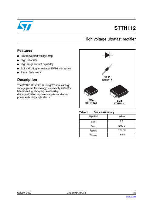
October 2009Doc ID 9343 Rev 51/8STTH112High voltage ultrafast rectifierFeatures■Low forwarded voltage drop ■High reliability■High surge current capability■Soft switching for reduced EMI disturbances ■Planar technologyDescriptionThe STTH112, which is using ST ultrafast high voltage planar technology, is specially suited for free-wheeling, clamping, snubbering,demagnetization in power supplies and other power switching applicationsTable 1.Device summarySymbol Value I F(AV) 1 A V RRM 1200 V T j (max) 175 °C V F (max)1.65 VElectrical characteristics STTH1122/8Doc ID 9343 Rev 51 Electrical characteristicsAbsolute ratings (limiting values)Symbol ParameterValue Unit V RRM Repetitive peak reverse voltage 1200V V (RMS)Voltage rms850VI F(AV)Average forward currentTl = 85°C δ =0.5DO-411ATl = 115°C δ =0.5SMA Tl = 125°C δ =0.5SMBI FSMForward surge current t = 8.3 ms DO-4120ASMA 18SMBT stg Storage temperature range- 50 + 175°C T jMaximum operating junction temperature+ 175°CTable 2.Thermal parametersSymbolParameterValue UnitR th (j-l)Junction to leadL = 10 mmDO-4145°C/W SMA 30SMB25R th (j-a)Junction to ambient L = 10 mm DO-41110Table 3.Static electrical characteristicsSymbol ParameterTests conditions Min.Typ.Max.Unit I RReverse leakage currentV R = 1200 VT j = 25 °C 5µAT j = 125 °C 50V FForward voltage dropI F = 1 A T j = 25 °C1.9V T j = 125 °C 1.17 1.65T j = 150 °C1.101.55Table 4.Dynamic electrical characteristicsSymbol ParameterTests conditionsMin.Typ.Max.Unit t rr Reverse recovery time I F = 0.5 AI rr = 0.25 A I R = 1A T j = 25 °C 75ns t fr Forward recovery time I F = 1 AdI F /dt = 50 A/µs V FR = 1.1 x V FmaxT j = 25 °C500ns V FPForward recovery voltage30VSTTH112Electrical characteristicsDoc ID 9343 Rev 53/8Figure 1.Conduction losses versus averageFigure 2.Forward voltage drop versusFigure 3.Relative variation of thermal impedance junction ambient versus Figure 4.Relative variation of thermalimpedance junction ambient versusFigure 5.Relative variation of thermal impedance junction ambient versus Figure 6.Thermal resistance junction to ambient versus copper surfaceElectrical characteristics STTH112 Figure 7.Thermal resistance junction to ambient versus copper surface under each lead4/8Doc ID 9343 Rev 5STTH112Package informationDoc ID 9343 Rev 55/82 Package information●Epoxy meets UL 94, V0●Band indicates cathode●Bending method (DO-41): see Application note AN1471In order to meet environmental requirements, ST offers these devices in different grades ofECOPACK ® packages, depending on their level of environmental compliance. ECOPACK ® specifications, grade definitions and product status are available at: . ECOPACK ® is an ST trademark.Table 5.SMA dimensionsRef.DimensionsMillimeters Inches Min.Max.Min.Max.A1 1.90 2.450.0750.094A20.050.200.0020.008b1.25 1.650.0490.065c0.150.400.0060.016D 2.25 2.900.0890.114E4.805.350.1890.211E1 3.95 4.600.1560.181L0.751.500.0300.059ECLE1DA1A2bPackage informationSTTH1126/8Doc ID 9343 Rev 5Table 7.DO-41 (plastic) dimensionsRef.DimensionsMillimeters Inches Min.Max.Min.Max.A4.075.200.1600.205B 2.04 2.710.0800.107C 25.41D0.710.860.0280.034ØD ØBACCSTTH112Ordering informationDoc ID 9343 Rev 57/83 Ordering information4 Revision historyTable 8.Ordering informationOrder code Marking Package Weight Base qty Delivery Mode STTH112STTH112DO-41 0.34 g 2000Ammopack STTH112A H12SMA 0.068 g 5000Tape and reel STTH112U U12SMB 0.11 g 2500Tape and reel STTH112RLSTTH112DO-410.34 g5000Tape and reelTable 9.Document revision historyDate RevisionChangesJan-20032Initial release.22-Jun-20053New value of T j = 150 °C added to table 2.Dimensions A1 E and D updated in T able 4. Data sheet reformatted. No other technical changes.20-Mar-20074Reformatted to current standards. Updated dimensions and footprints for SMA and SMB packages.30-Sep-20095Updated table 7 package dimensions.STTH112Please Read Carefully:Information in this document is provided solely in connection with ST products. STMicroelectronics NV and its subsidiaries (“ST”) reserve the right to make changes, corrections, modifications or improvements, to this document, and the products and services described herein at any time, without notice.All ST products are sold pursuant to ST’s terms and conditions of sale.Purchasers are solely responsible for the choice, selection and use of the ST products and services described herein, and ST assumes no liability whatsoever relating to the choice, selection or use of the ST products and services described herein.No license, express or implied, by estoppel or otherwise, to any intellectual property rights is granted under this document. If any part of this document refers to any third party products or services it shall not be deemed a license grant by ST for the use of such third party products or services, or any intellectual property contained therein or considered as a warranty covering the use in any manner whatsoever of such third party products or services or any intellectual property contained therein.UNLESS OTHERWISE SET FORTH IN ST’S TERMS AND CONDITIONS OF SALE ST DISCLAIMS ANY EXPRESS OR IMPLIED WARRANTY WITH RESPECT TO THE USE AND/OR SALE OF ST PRODUCTS INCLUDING WITHOUT LIMITATION IMPLIED WARRANTIES OF MERCHANTABILITY, FITNESS FOR A PARTICULAR PURPOSE (AND THEIR EQUIVALENTS UNDER THE LAWS OF ANY JURISDICTION), OR INFRINGEMENT OF ANY PATENT, COPYRIGHT OR OTHER INTELLECTUAL PROPERTY RIGHT. UNLESS EXPRESSLY APPROVED IN WRITING BY AN AUTHORIZED ST REPRESENTATIVE, ST PRODUCTS ARE NOT RECOMMENDED, AUTHORIZED OR WARRANTED FOR USE IN MILITARY, AIR CRAFT, SPACE, LIFE SAVING, OR LIFE SUSTAINING APPLICATIONS, NOR IN PRODUCTS OR SYSTEMS WHERE FAILURE OR MALFUNCTION MAY RESULT IN PERSONAL INJURY, DEATH, OR SEVERE PROPERTY OR ENVIRONMENTAL DAMAGE. ST PRODUCTS WHICH ARE NOT SPECIFIED AS "AUTOMOTIVE GRADE" MAY ONLY BE USED IN AUTOMOTIVE APPLICATIONS AT USER’S OWN RISK.Resale of ST products with provisions different from the statements and/or technical features set forth in this document shall immediately void any warranty granted by ST for the ST product or service described herein and shall not create or extend in any manner whatsoever, any liability of ST.ST and the ST logo are trademarks or registered trademarks of ST in various countries.Information in this document supersedes and replaces all information previously supplied.The ST logo is a registered trademark of STMicroelectronics. All other names are the property of their respective owners.© 2009 STMicroelectronics - All rights reservedSTMicroelectronics group of companiesAustralia - Belgium - Brazil - Canada - China - Czech Republic - Finland - France - Germany - Hong Kong - India - Israel - Italy - Japan - Malaysia - Malta - Morocco - Philippines - Singapore - Spain - Sweden - Switzerland - United Kingdom - United States of America8/8Doc ID 9343 Rev 5Mouser ElectronicsAuthorized DistributorClick to View Pricing, Inventory, Delivery & Lifecycle Information:S TMicroelectronics:STTH112RL STTH112U STTH112A。
爱立信PDG22F0025TFFL电源防护模具电路保护器说明书
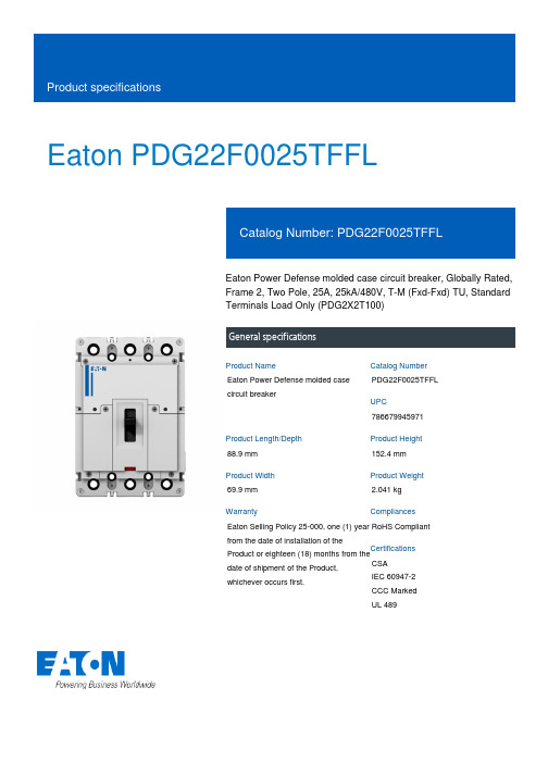
Eaton PDG22F0025TFFLEaton Power Defense molded case circuit breaker, Globally Rated, Frame 2, Two Pole, 25A, 25kA/480V, T-M (Fxd-Fxd) TU, Standard Terminals Load Only (PDG2X2T100)General specificationsEaton Power Defense molded case circuit breakerPDG22F0025TFFL 78667994597188.9 mm 152.4 mm 69.9 mm 2.041 kg Eaton Selling Policy 25-000, one (1) year from the date of installation of theProduct or eighteen (18) months from thedate of shipment of the Product,whichever occurs first.RoHS Compliant CSAIEC 60947-2CCC MarkedUL 489Product NameCatalog Number UPCProduct Length/Depth Product Height Product Width Product Weight WarrantyCompliancesCertifications25 AComplete breaker 2Two-polePD2 Global Class A T-M (Fxd-Fxd) TU600 Vac600 VStandard Terminals Load Only25 kAIC at 480 Vac 25 kAIC Icu/ 20 kAIC Ics/ 52.5 kAIC Icm @440V (IEC) 25 kAIC @480V (UL) 14 kAIC @600V (UL/CSA)18 kAIC Icu/ 15/13 kAIC Ics/ 37.8 kAIC Icm @525V South Africa (IEC)35 kAIC Icu/ 35 kAIC Ics/ 73.5 kAIC Icm @240V (IEC) 10 kAIC Icu @250 Vdc20 kAIC Icu/ 20 kAIC Ics/ 42 kAIC Icm @480V Brazil (IEC) 10 kAIC Icu @125 Vdc 35 kAIC @240V (UL)25 kAIC Icu/ 25 kAIC Ics/ 52.5 kAIC Icm @380-415V (IEC)Eaton Power Defense PDG22F0025TFFL 3D drawing Consulting application guide - molded case circuit breakers Amperage Rating Circuit breaker frame type Frame Number of poles Circuit breaker type Class Trip Type Voltage rating Voltage rating - max TerminalsInterrupt rating Interrupt rating range3D CAD drawing packageApplication notesBrochuresPower Defense technical selling bookletPower Defense molded case circuit breaker selection posterPower Defense brochurePower Defense molded case circuit breakers - Frame 2 product aid CatalogsMolded case circuit breakers catalogCertification reportsEU Declaration of Conformity - Power Defense molded case circuit breakersPDG4 CB reportPDG4 CCC certificationPDG2 CB reportPower Defense Declaration concerning California’s Proposition 65 Installation instructionsPower Defense Frame 2 screw terminal_end cap kit, 225A, 2 pole instructions - IL012257EN H01Power Defense Frame 2 multi wire connector kit -PDG2X3(2)(4)TA2253W instructions - IL012243EN H01Power Defense Frame 2/3/4/5/6 voltage neutral sensor module wiring instructions – IL012316ENPower Defense Frame 2 multi wire connector kit -PDG2X3(2)(4)TA2256W instructions - IL012242EN H01Power Defense Frame 2 PDG2 and PDC(E)9 breaker instructions -IL012106ENPower Defense Frame 2 tunnel terminal kits - PDG2X1TA225K instructions- IL012239EN H01Power Defense Frame 2 terminal kit - PDG2X3(2)(4)TA225RF instructions - IL012245EN H01Power Defense Frame 2 tunnel terminal (aluminum), 50A, 2 pole instructions - IL012236EN H02Power Defense Frame 2 global terminal shield, 2 pole - IL012330EN Power Defense Frame 1 IEC and Frame 2 Rotary Mechanism with NFPA Handle Attachment Instructions (IL012260EN).pdfPower Defense Frame 2 box terminal (steel), 100A, 2 pole instructions - IL012234EN H02Power Defense Frame 2 clamp terminal (steel), 20A, 2 pole instructions - IL012246EN H02Power Defense Frame 2 terminal kit - PDG2X3(2)(4)TA150RF instructions - IL012244EN H01Power Defense Frame 2 locking devices and handle block instructions - IL012149ENPower Defense Frame 1-2-3-4 IP door barrier assembly instructions - IL012278ENPower Defense Frame 2 tunnel terminal (aluminum), 150A, 2 pole instructions - IL012238EN H02Power Defense Frame 2 tunnel terminal (aluminum), 100A, 2 pole instructions - IL012237EN H02Power Defense Frame 2 global interphase barrier 2 pole – IL012324ENInstallation videosPower Defense Frame 2 TMTU Aux, Alarm, ST and UVR Animated Instructions.rhPower Defense Frame 2 withTMTU, Shunt Trip_UVR Animated Instructions.rhMultimediaPower Defense Frame 3 Variable Depth Rotary Handle Mechanism Installation How-To VideoEaton Power Defense for superior arc flash safetyPower Defense Frame 5 Trip Unit How-To VideoPower Defense Frame 6 Trip Unit How-To VideoPower Defense BreakersPower Defense Frame 2 Variable Depth Rotary Handle Mechanism Installation How-To VideoPower Defense molded case circuit breakersSpecifications and datasheetsEaton Specification Sheet - PDG22F0025TFFLTime/current curvesPower Defense time current curve Frame 2 - PD2Warranty guidesSelling Policy 25-000 - Distribution and Control Products and ServicesWhite papersMaking a better machineMolded case and low-voltage power circuit breaker healthIntelligent circuit protection yields space savingsSingle and double break MCCB performance revisitedMolded case and low-voltage breaker healthSafer by design: arc energy reduction techniquesEaton Corporation plc Eaton House30 Pembroke Road Dublin 4, Ireland © 2023 Eaton. All Rights Reserved. Eaton is a registered trademark.All other trademarks areproperty of their respectiveowners./socialmedia。
Hoffman Enclosures 机械室内外冷却器说明 说明书
Shipping Weight (kg) 12 21
Standard Product T20 Series
Full
BTU/Hr. @ Max.
Load
60 Hz Max.
60 Hz Max.
Shipping
Shipping
Catalog Number
Voltage
Hz
Phase
Ambient Temp.
Thermal Management: Air Conditioners
Air Conditioners
SEPFApXHire((C7c7-6o603n30))d144i82t21i22o--n226e20r1s10
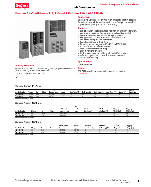
TheArimr Caol Mndaintiaogneemrsent
Outdoor Air C00-4,000 BTU/Hr.
Air Conditioners
2
Subject to change without notice
PH (763) 422-2211 • FX (763) 422-2600 •
© 2009 Hoffman Enclosures Inc. Spec-00181 E
Thermal Management: Air Conditioners
Air Conditioners
4
Subject to change without notice
PH (763) 422-2211 • FX (763) 422-2600 •
© 2009 Hoffman Enclosures Inc. Spec-00181 E
Air Conditioners
Subject to change without notice
SureSAS112f产品彩页
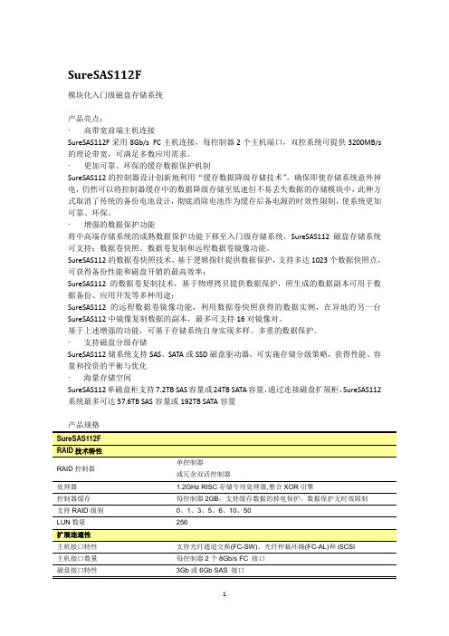
SureSAS112F模块化入门级磁盘存储系统产品亮点:∙高带宽前端主机连接SureSAS112F采用8Gb/s FC主机连接,每控制器2个主机端口,双控系统可提供3200MB/s 的理论带宽,可满足多数应用需求。
∙更加可靠、环保的缓存数据保护机制SureSAS112的控制器设计创新地利用“缓存数据降级存储技术”,确保即使存储系统意外掉电,仍然可以将控制器缓存中的数据降级存储至低速但不易丢失数据的存储模块中,此种方式取消了传统的备份电池设计,彻底消除电池作为缓存后备电源的时效性限制,使系统更加可靠、环保。
∙增强的数据保护功能将中高端存储系统的成熟数据保护功能下移至入门级存储系统,SureSAS112磁盘存储系统可支持:数据卷快照、数据卷复制和远程数据卷镜像功能。
SureSAS112的数据卷快照技术,基于逻辑指针提供数据保护,支持多达1023个数据快照点,可获得备份性能和磁盘开销的最高效率;SureSAS112的数据卷复制技术,基于物理拷贝提供数据保护,所生成的数据副本可用于数据备份、应用开发等多种用途;SureSAS112的远程数据卷镜像功能,利用数据卷快照获得的数据实例,在异地的另一台SureSAS112中镜像复制数据的副本,最多可支持16对镜像对。
基于上述增强的功能,可基于存储系统自身实现多样、多重的数据保护。
∙支持磁盘分级存储SureSAS112储系统支持SAS、SATA或SSD磁盘驱动器,可实施存储分级策略,获得性能、容量和投资的平衡与优化∙海量存储空间SureSAS112单磁盘柜支持7.2TB SAS容量或24TB SATA容量,通过连接磁盘扩展柜,SureSAS112系统最多可达57.6TB SAS容量或192TB SATA容量产品规格RAID控制器单控制器或冗余双活控制器处理器 1.2GHz RISC存储专用处理器,整合XOR引擎控制器缓存每控制器2GB,支持缓存数据的掉电保护,数据保护无时效限制支持RAID级别0、1、3、5、6、10、50LUN数量256主机接口特性支持光纤通道交换(FC-SW)、光纤仲裁环路(FC-AL)和iSCSI主机接口数量每控制器2个8Gb/s FC 接口磁盘接口特性3Gb或6Gb SAS 接口外形尺寸2U 高19英寸机架设备(8.9cm H×44.7cm W×54.0cm D) 重量27.2 kg 支持硬盘容量600GB (6Gb/s SAS,15krpm) 2TB (SATA, 7200rpm) * 可订货配置请以产品调整方案为准 支持最大硬盘数量96 风扇和电源双冗余、热插拔最大缓存突发读I/O 速率 264,000 IOPS 温度5ºC - 40ºC 湿度10% - 90% (非凝结环境) 功率436W(最大持续功率) 支持操作系统 Windows 2003/2008 Linux Novell NetWare VMware IBM AIXHP-UXSUN SolarisSGI-IRIX光纤设备支持 Brocade EmulexLSI QLogic 数据卷快照 1023数据卷复制 1023数据卷镜像可创建最多16个远程镜像对; 支持同步和异步镜像支持硬盘数量单柜支持12个SAS 或SATA 硬盘 支持硬盘容量 600GB (6Gb/s SAS,15krpm) 2TB (SATA, 7200rpm)* 可订货配置请以产品调整方案为准风扇和电源双冗余、热插拔 外形尺寸 2U 高19英寸机架设备(8.9cm H×44.7cm W×54.0cm D)。
OUSAF22技术参数表
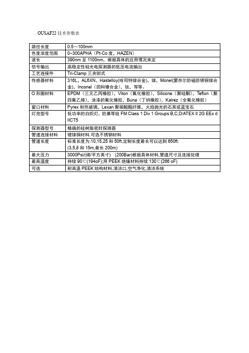
耐高温PEEK结构材料,清洁口,空气净化,清洁系统
O形圈材料
EPDM(三元乙丙橡胶),Viton(氟化橡胶),Silicone(聚硅酮),Teflon(聚四氟乙烯),涂漆的氟化橡胶,Buna(丁纳橡胶),Kalrez(全氟化橡胶)
窗口材料
Pyrex耐热玻璃,Lexan聚碳酸酯纤维,火焰抛光的石英或蓝宝石
灯泡型号
低功率的白炽灯,防暴等级FM Class 1Div1 Groups B,C,D/ATEX II 2GEExd IICT5
探测器型号
精确的硅树脂密封探测器
管道连接材料
镀镍铜材料.可选不锈钢材料
管道长度
标准长度为:10,15,25和50ft.定制长度最长可以达到650ft.
(3,5,8和15m,最长200m)
最大压力
3000Psi/(磅/平方英寸) (200Bar)根据具体材料,管道尺寸及连接处理
最高温度
持续90℃(194oF);用PEEK绝缘材料持续130℃(266oF)
OUSAF22技术参数表
路径长度
0.5~100mm
色度浓度范围
0~300APHA(Pt-Co度,HAZEN)
波长
390nm至11ቤተ መጻሕፍቲ ባይዱ0nm,根据具体的应用情况来定
信号输出
高稳定性硅光电探测器的低压电流输出
工艺连接件
Tri-Clamp三夹钳式
传感器材料
316L,AL6XN,Hastelloy(哈司特镍合金),镍,Monel(蒙奈尔防磁防锈铜镍合金),Inconel(因科镣合金),钛,等等。
- 1、下载文档前请自行甄别文档内容的完整性,平台不提供额外的编辑、内容补充、找答案等附加服务。
- 2、"仅部分预览"的文档,不可在线预览部分如存在完整性等问题,可反馈申请退款(可完整预览的文档不适用该条件!)。
- 3、如文档侵犯您的权益,请联系客服反馈,我们会尽快为您处理(人工客服工作时间:9:00-18:30)。
______________________________________________________________________________________________________ VI TELEFILTER Vectron International, Inc. Potsdamer Straße 18 267 Lowell Road D 14 513 TELTOW / Germany Hudson, NH 03051 / USA Tel: (+49) 3328 4784-52 / Fax: (+49) 3328 4784-30 Tel: (603) 598-0070 Fax: (603) 598-0075Measurement condition Ambient temperature: 23 °C Input power level: 10 dBmTerminating impedances for input: 800 Ω || -12,0 pF for output: 1,1 k Ω || -12,2 pFCharacteristicsRemark:Reference level for the relative attenuation a rel of the TFS 112 F is the minimum of the pass band attenuation a min . The minimum of the pass band attenuation a min is defined as the insertion loss a e . The reference frequency f c is the arithmetic mean value of the upper and lower frequencies at the 30 dB filter attenuation level relative to the insertion loss a e .D a t atyp. value tolerance / limit____________________________________________________________________________________________________Insertion loss a e = a min - 14,0 dB(reference level)____________________________________________________________________________________________________ Reference frequency f c (30 dB-BW) 112,32 MHz ± 60 kHz____________________________________________________________________________________________________1.5 dB bandwidth BW min. 360 kHz3 dB bandwidthBW min. 500 kHz____________________________________________________________________________________________________Relative attenuationa rel f c ± 800 kHz f c ± 1.6 MHz - 30 dB f c ± 1.6 MHz f c ± 10 MHz - 40 dB____________________________________________________________________________________________________ Group delayGD Ripple f c ± 150 kHz max 300 ns____________________________________________________________________________________________________Operating temperature range0 °C ... + 70 °C Storage temperature range- 45 °C ... + 85 °C ____________________________________________________________________________________________________ Input power level - max. + 10 dBm____________________________________________________________________________________________________ Permissible DC voltage V DC -12 V Permissible AC voltage V pp -10 V ____________________________________________________________________________________________________ Temperature coefficient of frequencyTC f *) - 0,036pm/K² - ______________________________________________________________________________________________________ Frequency inversion temperature T o 5°C______________________________________________________________________________________________________*) ∆f(Hz) = TC f (ppm/K²) x (∆T)² x f To (MHz)Generated:Checked / approved:______________________________________________________________________________________________________ VI TELEFILTER Vectron International, Inc. Potsdamer Straße 18 267 Lowell Road D 14 513 TELTOW / Germany Hudson, NH 03051 / USA Tel: (+49) 3328 4784-52 / Fax: (+49) 3328 4784-30 Tel: (603) 598-0070 Fax: (603) 598-0075Construction, pin connection and 50 Ω - matching network(All dimensions in mm)TFS112F tft L9______________________________________________________________________________________________________ VI TELEFILTER Vectron International, Inc. Potsdamer Straße 18 267 Lowell Road D 14 513 TELTOW / Germany Hudson, NH 03051 / USA Tel: (+49) 3328 4784-52 / Fax: (+49) 3328 4784-30 Tel: (603) 598-0070 Fax: (603) 598-0075Stability characteristicsAfter the following tests the filter shall meet the whole specification:1. Shock: 500g, 18 ms, half sine wave, 3 shocks each plane;DIN IEC 68 T2 - 272. Vibration: 10 Hz to 500 Hz, 0,35 mm or 5g respectively, 1 octave per min, 10 cycles per plan, 3 plans;DIN IEC 68 T2 - 63. Damp heat: 25 °C to 55°C / 95% r.H. / 10 cycles (cycle)DIN IEC 68 - 2 – 30 Db4. Resistance tosolder heat (reflow): max. 2 times reflow process;for temperature conditions refer to the attached "Air reflow temperature conditions" on page 4;PackingTape & Reel: IEC 286 - 3, with exception of value for N and minimum bending radius; tape type II , embossed carrier tape with top cover tape on the upper side;max. pieces of filters per reel: 1700Real of empty components at start: min 300 mm Real of empty components at start including leader:min 500 mmTrailermin 300 mmCOVER TAPETape (all dimensions in mm)W : 24 ± 0,3Po : 4 ± 0,1Do : 1,5 + 0,1 E : 1,75 ± 0,1F : 11,5 ± 0,1G (min) : 0,6P2 : 2 ± 0,1P1 : 12 ± 0,1D1(min) : 1,5Ao : 7,1 ± 0,2Bo : 13,9 ± 0,2D1 : 1,5 + 0,1NW 1W 2Reel (all dimensions in mm):A : 330W1 : 24,4 +2W2 (max) : 30,4N (min) : >= 60C : 13 + 0,5- 0,2The minimum bending radius is 45 mm. The mounting surface of the filters faces the bottom side of the embossed carrier tape. The marking of the filters is able to read if the view is directed on the upper side of the carrier tape with the sprocket holes on the right side of the tap______________________________________________________________________________________________________VI TELEFILTER Vectron International Inc. Potsdamer Straße 18 267 Lowell Road D 14 513 TELTOW / Germany Hudson, NH 03051 / USA Tel: (+49) 3328 4784-52 / Fax: (+49) 3328 4784-30 Tel: (603) 598-0070 Fax: (603) 598-0075 E-Mail: tft@ E-Mail: vti@VI TELEFILTER reserves the right to make changes to the product(s) and/or information contained herein without notice. No liability isAir reflow temperature conditions1st and 2nd air reflow profileName:pre-heating periods main-heating periods peak temperature Temperature: 150 °C - 170 °C over 200 °C 255 °C ± 5 °CTime:60 sec. - 90 sec.20 sec. - 25 sec.Tolerance of temperatures: ± 5 °C time / sec. temperature / °C time / sec. temperature / °C 0 23 140 160 10 34 150 161 20 46 160 164 30 60 170 170 40 80 180 180 50 103 190 205 60 121 195 230 70 134 200 255 80 143 205 230 90 150 210 205 100 154 215 180 110 156 220 165 120 158 230 140 130 159 240 120。