CCNA(Stand-ALONE)Lab 27-Standard Access Lists
NVIDIA Jetson AGX Orin系列产品数据手册说明书

P3701 | NVIDIA JETSON AGX ORIN SERIESDATASHEETDiscover the most powerful AI computer for energy-efficient autonomous machines.NVIDIA ® Jetson AGX Orin ™ series modules deliver up to 275 TOPS of AI performance with power configurable between 15W and 60W. This gives you more than 8X theperformance of Jetson AGX Xavier ™ in the same compact form-factor for robotics and other autonomous machine use cases.These system-on-modules support multiple concurrent AI application pipelines with an NVIDIA Ampere architecture GPU, next-generation deep learning and visionaccelerators, high-speed IO, and fast memory bandwidth. Now, you can develop solutions using your largest and most complex AI models to solve problems such as natural language understanding, 3D perception, and multi-sensor fusion.Jetson runs the NVIDIA AI software stack, and use case-specific application frameworks are available, including NVIDIA Isaac ™ for robotics, DeepStream for vision AI, and Riva for conversational AI. You can also save significant time with NVIDIA Omniverse ™ Replicator for synthetic data generation (SDG), and with NVIDIA TAO Toolkit for fine-tuning pretrained AI models from the NGC ™ catalog.Jetson ecosystem partners offer additional AI and system software, developer tools, and custom software development. They can also help with cameras and other sensors, as well as carrier boards and design services for your product.Jetson Orin modules are unmatched in performance and efficiency for robots and other autonomous machines, and they give you the flexibility to create the next generation of AI solutions with the latest NVIDIA GPU technology. Together with the world-standard NVIDIA AI software stack and an ecosystem of services and products, your road to market has never been faster.Jetson AGX Orin 32GB>1792-core NVIDIA Ampere architecture GPU with 56 tensor cores >2x NVDLA v2.0>8-core Arm® Cortex®-A78AE v8.2 64-bit CPU>32GB 256-bit LPDDR5 >64GB eMMC 5.1 >PVA v2.0Power>Voltage input 5V, 7V-20V >Module Power: 15W - 40WKey FeaturesJetson AGX Orin 64GB>2048-core NVIDIA Ampere architecture GPU with 64 tensor cores >2x NVDLA v2.0>12-core Arm® Cortex®-A78AE v8.2 64-bit CPU>64GB 256-bit LPDDR5 >64GB eMMC 5.1 >PVA v2.0Power>Voltage input 5V, 7V-20V >Module Power: 15W - 60WNVIDIA JETSON AGX ORIN SERIES MODULES TECHNICAL SPECIFICATIONS* Virtual channel-related camera information for Jetson AGX Orin is not final and subject to change.Refer to the Software Features section of the latest NVIDIA Jetson Linux Developer Guide for a list of supportedfeatures.。
5G考试题库
网上大学5G题库1、()属于5GC的基本功能模块答案:ABC A、AMF B、SMF C、UPFD、RFS2、“满足商用要求”网管指标有答案:ABCD A、1)接入类B、2)保持类C、3)移动性D、4)运维类3、360度全景VR直播演示方案中需要以下哪个设备答案:ABCD A、1)5GNR B、2)360全景摄像头C、3)显示屏D、4)TUE4、3GPP R16 5G语音业务会支持哪些技术?答案:ABD A、EPSFBB、VoNRC、CSFBD、SRVCC5、4/5G链路预算的主要差异答案:ACD A、1)最大带宽不同B、2)所处频段不同C、3)基站天线端口数不同D、4)终端天线端口数不同6、4G双锚点方案需要考虑的因素有?答案:CD A、4GRRU容量评估B、CPRI接口光模块容量评估C、到核心网路由的互联互通D、基站IP 地址是否新增7、5GNR版本包包含哪些版本文件答案:BC A、产品tar文件B、产品平台版本包C、基础包pkg文件D、RRU版本包8、5GNR覆盖能力提升主要依靠:答案:ABC A、MassiveMIMO B、终端能力加强C、大带宽D、30k的子载波间隔9、5GNR可以采用哪些方式来增强上行覆盖()答案:BC A、增加SDL频段B、载波聚合C、增加SUL频段D、以上均可10、5GNR目前支持的BWP带宽包括()答案:BD A、30MHz B、60MHz C、70MHz D、100MHz11、5GQcellR8139F1821T35机型的哪些通道支持5G?答案:AB A、7&8B、5&6C、3&4D、1&212、5GQCell安装时,PB与pRRU之间可以使用哪些物理介质连接?答案:ABC A、光电复合缆缆B、CAT6A网线C、CAT6网线D、CAT5E网线13、5GTUE支持的下行流数是答案:ABCD A、3 B、1 C、4 D、214、5GSA组网方式下BBU使用单板有答案:ABDE A、vPD B、vFC C、vbpc1 D、vBPc5 E、VSWc215、5G大容量保障启动前,为提高效率且保证保障顺利进行,哪些准备工作需要外场提前完成?答案:ABCD A、站点建设或改造B、单站基础性能优化C、覆盖摸底测试D、大话务参数部署16、5G大容量保障时,PM实时查询的粒度为?答案:BCD A、1s B、10sC、30sD、1分钟17、5G大容量保障时,档位分为几档?答案:BD A、20UE B、50UE C、100UE D、200UE18、5G大容量保障时,高话务档位参数按照哪些维度进行分类?答案:BCD A、1)站型B、2)带宽C、3)档位D、4)帧结构19、5G大容量保障时,高话务档位参数按照那些维度进行分类?答案:BCD A、站型B、带宽C、档位D、帧结构20、5G大容量保障时,基线参数按照哪些维度进行分类?答案:BCDA、档位B、站型C、带宽D、帧结构21、5G大容量保障时,使用的用户容量档位有哪几档?答案:ACA、200UEB、100UEC、50UED、20UE22、5G单验前,需要提前准备的工具有哪列?答案:ABCD A、带倾角功能的罗盘 B、数字万用表 C、测试笔记本 D、电子地图23、5G单验时,BBU侧验收包括哪些项?答案:ABCD A、机柜测硬件布放顺序 B、BBU单板安装验收C、光纤安装验收D、GPS安装验收24、5G单验时,站点状态核查包括哪些项目?答案:ABCD A、告警确认B、单板运行状态检查C、时钟状态检查D、小区状态检查25、5G的三大业务场景包括()答案:ABC A、URLLC B、eMMBC、mMTCD、BOB26、5G的上行物理信号包括()答案:ACD A、DM-RS B、CSI-RSC、PT-RSD、SRS27、5G定义的三个应用场景()答案:ACD A、eMBB B、eMTCC、mMTCD、uRLLC28、5G定义哪几种RRC状态答案:ABC A、RRC_CONNECTED B、RRC_IDLE C、RRC_INACTIVE D、RRC_ACTIVE29、5G独立组网的优势有答案:ABCD A、对现有2G/3G/4G网络无影响B、不影响现网2G/3G/4G用户C、可快速部署,直接引入5G新网元,不需要对现网改造D、引入5GC,提供5G新功能新业务30、5G规范定义了哪三种业务场景答案:BCD A、NB-IOT B、eMBBC、mMTCD、uRLLC31、5G核心网SMF的功能包括答案:BC A、移动性管理 B、IP地址分配C、会话管理与计费D、外部网关管理32、5G基础覆盖优化可通过哪些手段调整()答案:ABCD A、下倾角B、方位角C、pssSssPwr功率配置D、站高33、5G商用BBU—V9200交换板VSW的主要功能是:答案:BCD A、处理3GPP规定的物理层协议和帧协议B、控制管理基带单元C、提供传输接口D、提供系统时钟34、5G商用ITBBU—V9200的安装方式为答案:ABCD A、1)19英寸机柜安装B、2)挂墙安装 C、3)室外一体化机柜安装D、4)龙门架安装35、5G时隙类型中,上行自包含类型里存在()信道答案:ABCD A、PDCCH B、GP C、SRS D、PUSCH36、5G实验局组网总体原则下面哪些正确?答案:ABD A、先宏站后室分B、优先采用低频C、优先采用NSA D、CU/DU建议合设37、5G实验网阶段测试工作所需工具主要包含()答案:ACDE A、LMTB、TEMSC、DSPMonitorD、CRTE、CXT/CXA38、5G使用的主要编码方式是()答案:AC A、Polar B、TurboC、LDPCD、FMO39、5G试验网阶段测试优化工作所需工具主要包含答案:ABCDE A、LMT,B、罗德扫频仪,C、DSPMonitor,D、CRT,E、CXT40、5G室分的关键技术包括答案:ABCD A、1)超密组网 B、2)虚拟nTnR C、3)动态虚拟小区D、4)MEC增值服务方案41、5G室分建设的特征的数字化指答案:ABC A、网络结构数字化,B、运维数字化,C、业务数字化,D、建设数字化42、5G网管自定义方式配置权值时,涉及的参数包括答案:ABCD A、子波束索引B、水平及垂直波瓣宽度C、方位角D、下倾角43、5G网络建议使用4TRPAD或高频小站的用处是:答案:ABC A、热点覆盖 B、补盲覆盖C、建设难度大成本高解决方案 D、价格便宜44、5G小微站产品都有哪些类型答案:AB A、PAD B、iMacro C、Nanocell D、Qcell E、DAS45、5G站点开通,帧结构类型一般配置为答案:AD A、5ms单周期B、2.5ms单周期C、5ms双周期D、2.5ms双周期46、5G支持的参考信号有哪些答案:ABD A、SRS B、CSI-RS C、CRSD、DMRS47、5G支持的参考信号有哪些?答案:ABD A、DMRS B、SRS C、CRSD、CSI-RS48、5G支持的子载波间隔有()答案:ABCD A、15K B、30K C、60KD、120K49、5G智能网络规划需要依托的4G现网数据包括:答案:ABCD A、4G 网络数据统计B、4GMR数据C、4G现网站点数据库D、电子地图50、5NNR版本包包含那些版本文件?答案:AC A、产品tar文件B、平台版本包C、基础包pkg文件D、RRU版本包51、64TR产品推荐应用于以下哪些场景:答案:AB A、密集城区B、一般城区C、郊区D、农村52、8槽位VBPc5单板的三个MCS片的地址分别是答案:ACE A、192.254.8.16 B、192.254.8.32 C、192.254.8.48 D、192.254.8.64E、192.254.8.8053、A9611可以使用哪种电源线供电答案:CD A、2*4mm2 B、2*6mm2C、2*10mm2D、2*16mm254、A9631A有哪几款户外直流电源线缆规格可选?答案:BCD A、2*4mm2B、2*6mm2C、2*10mm2D、2*16mm255、AAPC现网当前的版本配置为SP03版本,下列哪些配置可能导致AAPC 的失败?答案:ABCD A、同一个任务内协同小区间缺少Xn配置B、协同小区间未配置邻区关系C、服务小区的初始权值的配置值未在权值库中 D、协同小区的初始权值配置值未在权值库中56、AAPC支持多种波束组合的权值寻优,支持下列哪几种波束个数组合的寻优。
英文版CCNA上面的单词
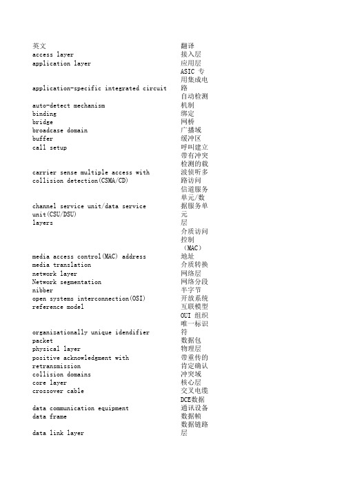
英文翻译access layer接入层application layer应用层application-specific integrated circuit ASIC 专用集成电路auto-detect mechanism自动检测机制binding绑定bridge网桥broadcase domain广播域buffer缓冲区call setup呼叫建立carrier sense multiple access with collision 带有冲突检测的载波侦听多路访问channel service unit/data service unit(CSU/DS信道服务单元/数据服务单元layers层media access control(MAC) address 介质访问控制(MAC)地址media translation介质转换network layer网络层Network segmentation网络分段nibber半字节open systems interconnection(OSI) reference m开放系统互联模型organizationally unique idendifier OUI 组织唯一标识符packet数据包physical layer物理层positive acknowledgment with retransmission带重传的肯定确认collision domains冲突域core layer核心层crossover cable交叉电缆data communication equipment DCE数据通讯设备data frame数据帧data link layer数据链路层data terminal equipment DTE数据终端设备datagram数据报de-encapsulation解封装desktop layer桌面层distribution layer分配层encapsulation封装层ethernet以太网flow control流量控制frame帧full duplex全双工half duplex半双工hierarchy层次hop count跳数hub集线器layered architecture层次化的体系结构presentation layer表示层protocol data units PDUs 协议数据单元reference model参考模型registered jack已注册的的插座(RJ)连接器rolled cable反转电缆router protocols被动路由协议routers路由器session layer会话层simplex单工state transitions状态转换straight-through cable直通电缆switches交换机thicknet粗缆网thinnet细览网three-way handshake三次握手transparent bridging透明网桥transport layer传输层tunneling隧道技术unshielded twisted-pair UTP 非屏蔽双绞线window窗口workgroup layer工作组层address resolution protocol ARP 地址解析协议bit位broadcast address广播地址byte字节calss a network A类网络class b network B类网络class c netword C类网络connectionless无连接的connection-oriented面向连接的Domain Name service DNS 域名服务network access layer网络接入层network address网络地址network address translation NAT 网络地址转换network file system NFS 网络文件系统node address节点地址octet八位位组outside network外部网络port address translation PAT 端口地址转换port number端口号process/application layer过程/应用层dynamic host configuration protocol动态主机配置协议DHCPfile transfer protocol FTPfully qualified domain name FQDN 完全合格域名hierarchical address分层寻址host address主机地址host-to-host layer主机到主机层inside control message protocol ICMP 因特网控制信息协议internet layer因特网层internet protocol因特网协议 IPip address IP地址logical address逻辑地址multicast组播nulticast group组播组RARP server RARP服务器reverse address resolution protocol RARP 反向地址解析协议sequencing排序simple mail transfer protocol SMTP 简单邮件传输协议simple network management protocol SNMP 简单网络管理协议software address软件地址telnet远程登录transmission control protocol TCP 传输控制协议transmission control protocol/internet protoc传输控制协议/因特网协议trivial file transfer protocol TFTP 简单文件传输协议user datagram protocol UDP 用户数据报协议virtual circuit虚电路x windows X windows。
阿尔伦-布拉德利 Stratix 5700 工业 managed Ethernet 交换机说明书

Stratix 5700Industrial Managed Ethernet SwitchThe wide deployment of EtherNet/IP™ in industrial automation means that there is a growing demand to manage the network properly.Integtrating new machine-level networks into an existing plant network requires convergence.With more devices connected on the same Ethernet network than ever before, an industrial managed switch can help you simplify your network infrastructure. Adding a managed switch to your network architecture can also help make the process of adding new machines easier. The Allen-Bradley® Stratix 5700™ is a compact, scalable Layer 2 managed switch with embedded Cisco technology for use in applications with small isolated, to complex networks. With integration into Studio 5000 Automation Engineering and Design Environment™, you canleverage FactoryTalk® View faceplates and Add-on Profiles for simplified configuration and monitoring.By choosing a switch co-developed by Rockwell Automation and Cisco, your Operations Technology (OT) and Information Technology (IT) professionals leverage tools and technology that are familiar to them. This collaboration can also help to reduce configuration time and cost.Features and Benefits:Advanced Networking Features• Integrated Device Level Ring (DLR) connectivity helps optimize the network architecture and provide consolidated network diagnostics • Integrated Network Address Translation (NAT) provides 1:1 IP address mapping helping to reduce commissioning time • Power over Ethernet (PoE) versions provide power to devices over Ethernet minimizing cabling • Security features, including access control lists, help ensure that only authorized devices, users and traffic can access the network • Secure Digital (SD) card provides simplified device replacementOptimized integration:• Studio 5000® Add-on Profiles (AOPs) enable premier integration into the Rockwell Automation Integrated Architecture® system • Predefined Logix tags for monitoring and port control • FactoryTalk® View faceplates enable status monitoring and alarming • Built-in Cisco® Internet Operating System (IOS) helps provide secure integration with enterprise networkDesigned and Developed for EtherNet/IP Automation ApplicationsNetwork Address TranslationMachine integration onto a plant network architecture can be difficult as machine builder IP-address assignments rarely match the addresses of the end-user network. Also, network IP addresses are often unknown until the machine is being installed. The Stratix 5700 with Network Address Translation (NAT) is a Layer 2 implementation that provides “wire speed” 1:1 translations ideal for automation applications where performance is critical.NAT allows for:• Simplified integration of IP-addressmapping from a set of local,machine-level IP addresses to theend user’s broader plant network• OEMs to deliver standard machinesto end users without programmingunique IP addresses• End users to more simply integratethe machines into the larger network192.168.1.4192.168.1.4MACHINE 1MACHINE 2Private Network Private NetworkSwitch Reference ChartAllen-Bradley Stratix 5700 Industrial Ethernet SwitchSwitch Selection TableFE - Fast Ethernet GE - Gigabit EthernetPublication ENET-PP005F-EN-E – April 2016Copyright ©2016 Rockwell Automation, Inc. All Rights Reserved. Printed in USA.Supersedes Publication ENET-PP005E-EN-E – March 2015EtherNet/IP is a trademark of the ODVA.Cisco is a trademark of Cisco Systems, Inc.Allen-Bradley, CompactLogix, Factory Talk, Integrated Architecture, Kinetix, LISTEN. THINK. SOLVE., Powerflex, Rockwell Automation, Rockwell Software, Stratix 5700, Studio 5000, Studio 5000 Automation Engineering and Design Environment are trademarks of Rockwell Automation, Inc.Glossary of TermsAccess Control Lists allow you to filter network traffic. This can be used to selectively block types of traffic to provide traffic flow control or provide a basic level of security for accessing your network.CIP port control and fault detection allows for port access based on Logix controller program or controller mode (idle/fault). Allows secure access to the network based on machine conditions.CIP SYNC (IEEE1588) is the ODVAimplementation of the IEEE 1588 precision time protocol. This protocol allows very high precision clock synchronization across automation devices. CIP SYNC is an enabling technology for time-critical automation tasks such as accurate alarming for post-event diagnostics, precision motion and high precision first fault detection or sequence of events.Device Level Ring (DLR) allows direct connectivity to a resilient ring network at the device level.DHCP per port allows you to assign a specific IP address to each port, confirming that the device attached to a given port will get the same IP address. This feature allows for device replacement without having to manually configure IP addresses.Encryption provides network security by encrypting administrator traffic during Telnet and SNMP sessions.EtherChannel is a port trunking technology. EtherChannel allows grouping several physical Ethernet ports to create one logical Ethernet port. Should a link fail, the EtherChannel technology will automatically redistribute traffic across the remaining links.Ethernet/IP (CIP) interface enables premier integration to the Integrated Architecture with Studio 5000 AOP , Logix tags and View Faceplates.FlexLinks provides resiliency with a quick recovery time and load balancing on a redundant star network.IGMP Snooping (Internet Group Management Protocol) constrains the flooding of multicast traffic by dynamically configuring switch ports so that multicast traffic is forwarded only to ports associated with a particular IP multicast group.* Separate SW IOS requiredKey Software FeaturesMAC ID Port Security checks the MAC ID of devices connected to the switch to determine if it is authorized. If not the device is blocked and the controller receives a warning message. This provides a method to block unauthorized access to the network.Network Address Translation (NAT) provides 1:1 translations of IP addresses from one subnet to another. Can be used to integrate machines into an existing network architecture.Port Thresholds(Storm control & Traffic Shaping)allows you to set both incoming and outgoing traffic limits. If a threshold is exceeded alarms can be set in the Logix controller to alert an operator. Power over Ethernet (PoE) provides electrical power along with data on a single Ethernet cable to end devices.QoS – Quality of Service (QoS) is the ability to provide different priority to different applications, users, or data flows, to help provide a higher level of determinism on your network.REP (Resilient Ethernet Protocol) – A ring protocol that allows switches to be connected in a ring, ring segment or nested ring segments. REP provides network resiliency across switches with a rapid recovery time ideal for industrial automation applications.Smartports provide a set of configurations to optimize port settings for common devices like automation devices, switches, routers, PCs and wireless devices. Smartports can also be customized for specific needs.SNMP Simple Network Management Protocol (SNMP) is a management protocol typically used by IT to help monitor and configure network-attached devices.Static and InterVLAN Routing bridges the gap between layer 2 and layer 3 routing providing limited static and connected routes across VLANs.STP/RSTP/MST Spanning Tree Protocol, is a feature that provides a resilient path between switches. Used for applications that requires a fault tolerant network.VLANs with Trunking is a feature that allows you to group devices with a common set of requirements into network segments. VLANs can be used to provide scalability, security and management to your network.802.1x Security is an IEEE standard for access control and authentication. It can be used to track access to network resources and helps secure the network infrastructure.。
CCNA实验手册[北京亚威教育]
![CCNA实验手册[北京亚威教育]](https://img.taocdn.com/s3/m/16a2b117866fb84ae45c8dd2.png)
1
亚威 CCNA 实验手册
实验一、配置 STP 与 VTP
环境: 三台交换机, 形成一个全互连结构, sw3 为 2950, sw1 和 sw2 为 2900xl; 要求:设置 sw3 为 VTP server,设置 sw1 和 sw2 为 VTP client,域名为 cisco, 密码为:cisco,在 server 创建 vlan 10(name:aa)和 vlan20(name:bb);设 置 sw3 为 vlan1 的根桥,sw1 为 vlan10 的根桥,sw2 为 vlan20 的根桥;
启用 trunk 端口
sw1 的配置: sw1(config)#interface fa0/23 sw1(config-if)#switchport trunk encapsulation dot1q 封装干道协议 sw1(config-if)#switchport mode trunk 启用 trunk 模式 sw1(config-if)# sw1(config)#interface fa0/24 sw1(config-if)#switchport trunk encapsulation dot1q sw1(config-if)#switchport mode trunk
2
亚威 CCNA 实验手册
sw3(config)#vtp domain cisco 设置域名 Changing VTP domain name from NULL to cisco sw3(config)#vtp password cisco 设置密码 Setting device VLAN database password to cisco sw1 的配置: sw1#vlan database 进入 vlan 数据库 sw1(vlan)#vtp client 启用 VTP client 模式 Setting device to VTP CLIENT mode. sw1(vlan)#vtp domain cisco 作用到 cisco 域中 Changing VTP domain name from NULL to cisco sw1(vlan)#vtp password cisco 设置密码与 server 端相同 Setting device VLAN database password to cisco. sw1(vlan)#exit 使配置生效 In CLIENT state, no apply attempted. Exiting.... sw2 的配置: sw2#vlan database sw2(vlan)#vtp client Setting device to VTP CLIENT mode. sw2(vlan)#vtp domain cisco Changing VTP domain name from NULL to cisco sw2(vlan)#vtp password cisco Setting device VLAN database password to cisco. sw2(vlan)#exit sw2# 步骤二、启用干道端口 sw3 的配置: sw3(config)#interface fa0/23 sw3(config-if)#switchport mode trunk sw3(config-if)#interface fa0/24 sw3(config-if)#switchport mode trunk
CCNA 实验手册
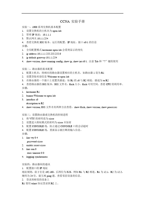
CCNA 实验手册实验一:1900系列交换机基本配置1.设置交换机的主机名为open-lab2.管理IP地址:10.1.1.13.默认网关10.1.1.2544.查看交换机IOS版本,运行的配置,IP地址,接口e0/1的信息步骤:1.全局配置模式hostname open-lab会看到显示的变化2.ip address 10.1.1.1 255.255.255.03.ip default-gateway 10.1.1.2544.show version, show running-config, show ip, show int e0/1. 注意Tab和“?”键的使用实验二:路由器的基本配置1.配置主机名:将相应的路由器设置相应的主机名,如路由器1设为R12.设置登陆欢迎信息Welcome to open-lab3.在路由器的一个接口上设置其描述,如R1的s0与R2相连,描述为to R24.查看路由器的IOS版本,IOS文件名,flash大小,flash可用空间。
查看CPU的利用率。
步骤:1.hostname R12.banner Welcome to open-lab3.interface s0description to R24.show version; IOS文件名有两种方法查看:show flash, show version; show processes实验三:设置路由器或交换机的控制进程1.将VTY的密码设为cisco2.设置进入特权模式的密码为cisco并加密3.配置CONSOLE线,防止通过CONSOLE口的会话超时4.配置CONSOLE线,重新显示被打断的输入信息。
步骤:1.line vty 0 4password cisco2.enable secret cisco3.line con 0exec-timeout 0 04.logging synchronous实验四:路由器间的通讯1.配置接口的IP地址地址规则:前2位是192.168,后两位为X.X。
MIPI_DSI_Specification_v1b_8320061508

MIPI Alliance Standard for Display Serial InterfaceV1.0MIPI Board approved 5 April 2006* Caution to Implementers *This document is a MIPI Specification formally approved by the MIPI Alliance Board of Directors per the process defined in the MIPI Alliance Bylaws. However, the Display Working Group has identified certain technical issues in this approved version of the specification that are pending further review and which may require revisions of or corrections to this document in the near future. Such revisions, if any, will be handled via the formal specification revision process as defined in the Bylaws.A Release Notes document has been prepared by the Display Working Group and is available to all members. The intent of the Release Notes is to provide a list of known technical issues under further discussion with the working group. This may not be an exhaustive list; its purpose is to simply catalog known issues as of this release date. Implementers of this specification should be aware of these facts, and take them into consideration as they work with the specification.Release Notes for the Display Serial Interface Specification can be found at the following direct, permanent link:https:///members/file.asp?id=4844MIPI Alliance Standard for Display Serial InterfaceVersion 1.00a – 19 April 2006MIPI Board Approved 5-Apr-2006Further technical changes to DSI are expected as work continues in the Display Working GroupNOTICE OF DISCLAIMER12The material contained herein is not a license, either expressly or impliedly, to any IPR owned or controlled 3by any of the authors or developers of this material or MIPI. The material contained herein is provided on 4an “AS IS” basis and to the maximum extent permitted by applicable law, this material is provided AS IS 5AND WITH ALL FAULTS, and the authors and developers of this material and MIPI hereby disclaim all 6other warranties and conditions, either express, implied or statutory, including, but not limited to, any (if7any) implied warranties, duties or conditions of merchantability, of fitness for a particular purpose, of8accuracy or completeness of responses, of results, of workmanlike effort, of lack of viruses, and of lack of 9negligence.10ALSO, THERE IS NO WARRANTY OF CONDITION OF TITLE, QUIET ENJOYMENT, QUIET11POSSESSION, CORRESPONDENCE TO DESCRIPTION OR NON-INFRINGEMENT WITH REGARD 12TO THIS MATERIAL OR THE CONTENTS OF THIS DOCUMENT. IN NO EVENT WILL ANY13AUTHOR OR DEVELOPER OF THIS MATERIAL OR THE CONTENTS OF THIS DOCUMENT OR 14MIPI BE LIABLE TO ANY OTHER PARTY FOR THE COST OF PROCURING SUBSTITUTE15GOODS OR SERVICES, LOST PROFITS, LOSS OF USE, LOSS OF DATA, OR ANY INCIDENTAL, 16CONSEQUENTIAL, DIRECT, INDIRECT, OR SPECIAL DAMAGES WHETHER UNDER17CONTRACT, TORT, WARRANTY, OR OTHERWISE, ARISING IN ANY WAY OUT OF THIS OR18ANY OTHER AGREEMENT, SPECIFICATION OR DOCUMENT RELATING TO THIS MATERIAL, WHETHER OR NOT SUCH PARTY HAD ADVANCE NOTICE OF THE POSSIBILITY OF SUCH1920DAMAGES.21Without limiting the generality of this Disclaimer stated above, the user of the contents of this Document is further notified that MIPI: (a) does not evaluate, test or verify the accuracy, soundness or credibility of the2223contents of this Document; (b) does not monitor or enforce compliance with the contents of this Document;24and (c) does not certify, test, or in any manner investigate products or services or any claims of compliance 25with the contents of this Document. The use or implementation of the contents of this Document may26involve or require the use of intellectual property rights ("IPR") including (but not limited to) patents,27patent applications, or copyrights owned by one or more parties, whether or not Members of MIPI. MIPI does not make any search or investigation for IPR, nor does MIPI require or request the disclosure of any2829IPR or claims of IPR as respects the contents of this Document or otherwise.30Questions pertaining to this document, or the terms or conditions of its provision, should be addressed to: 31MIPI Alliance, Inc.32c/o IEEE-ISTO33445 Hoes Lane34Piscataway, NJ 0885435Attn: Board SecretaryContents3637Version 1.00 – 13 April 2006 (i)381Overview (8)391.1Scope (8)401.2Purpose (8)412Terminology (Informational) (9)422.1Definitions (9)432.2Abbreviations (10)442.3Acronyms (10)453References (Informational) (13)463.1DBI and DBI-2 (Display Bus Interface Standards for Parallel Signaling) (13)473.2DPI and DPI-2 (Display Pixel Interface Standards for Parallel Signaling) (13)3.3DCS (Display Command Set) (14)48493.4CSI-2 (Camera Serial Interface 2) (14)503.5D-PHY (MIPI Alliance Standard for Physical Layer) (14)514DSI Introduction (15)524.1DSI Layer Definitions (16)534.2Command and Video Modes (17)4.2.1Command Mode (17)54554.2.2Video Mode Operation (17)564.2.3Virtual Channel Capability (18)5DSI Physical Layer (19)57585.1Data Flow Control (19)595.2Bidirectionality and Low Power Signaling Policy (19)605.3Command Mode Interfaces (20)615.4Video Mode Interfaces (20)625.5Bidirectional Control Mechanism (20)5.6.1Clock Requirements (21)64655.6.2Clock Power and Timing (22)666Multi-Lane Distribution and Merging (23)676.1Multi-Lane Interoperability and Lane-number Mismatch (24)686.1.1Clock Considerations with Multi-Lane (25)696.1.2Bi-directionality and Multi-Lane Capability (25)706.1.3SoT and EoT in Multi-Lane Configurations (25)717Low-Level Protocol Errors and Contention (28)727.1Low-Level Protocol Errors (28)737.1.1SoT Error (28)747.1.2SoT Sync Error (29)757.1.3EoT Sync Error (29)7.1.4Escape Mode Entry Command Error (30)76777.1.5LP Transmission Sync Error (30)787.1.6False Control Error (31)797.2Contention Detection and Recovery (31)807.2.1Contention Detection in LP Mode (32)817.2.2Contention Recovery Using Timers (32)7.3Additional Timers (34)82837.3.1Turnaround Acknowledge Timeout (TA_TO) (34)847.3.2Peripheral Reset Timeout (PR_TO) (35)7.4Acknowledge and Error Reporting Mechanism (35)85868DSI Protocol (37)878.1Multiple Packets per Transmission (37)888.2Packet Composition (37)898.3Endian Policy (38)908.4General Packet Structure (38)8.4.2Short Packet Format (40)92938.5Common Packet Elements (40)948.5.1Data Identifier Byte (40)958.5.2Error Correction Code (41)968.6Interleaved Data Streams (41)978.6.1Interleaved Data Streams and Bi-directionality (42)988.7Processor to Peripheral Direction (Processor-Sourced) Packet Data Types (42)998.8Processor-to-Peripheral Transactions – Detailed Format Description (43)1008.8.1Sync Event (H Start, H End, V Start, V End), Data Type = xx 0001 (x1h) (43)1018.8.2Color Mode On Command, Data Type = 00 0010 (02h) (44)1028.8.3Color Mode Off Command, Data Type = 01 0010 (12h) (44)1038.8.4Shutdown Peripheral Command, Data Type = 10 0010 (22h) (44)8.8.5Turn On Peripheral Command, Data Type = 11 0010 (32h) (44)1041058.8.6Generic Short WRITE Packet, 0 to 7 Parameters, Data Type = xx x011 (x3h and xBh) (44)1068.8.7Generic READ Request, 0 to 7 Parameters, Data Type = xx x100 (x4h and xCh) (44)1078.8.8DCS Commands (45)1088.8.9Set Maximum Return Packet Size, Data Type = 11 0111 (37h) (46)1098.8.10Null Packet (Long), Data Type = 00 1001 (09h) (46)8.8.11Blanking Packet (Long), Data Type = 01 1001 (19h) (46)1101118.8.12Generic Non-Image Data (Long), Data Type = 10 1001 (29h) (47)1128.8.13Packed Pixel Stream, 16-bit Format, Long packet, Data Type 00 1110 (0Eh) (47)8.8.14Packed Pixel Stream, 18-bit Format, Long packet, Data type = 01 1110 (1Eh) (48)1131148.8.15Pixel Stream, 18-bit Format in Three Bytes, Long packet, Data Type = 10 1110 (2Eh) (49)1158.8.16Packed Pixel Stream, 24-bit Format, Long packet, Data Type = 11 1110 (3Eh) (50)1168.8.17DO NOT USE and Reserved Data Types (50)1178.9Peripheral-to-Processor (Reverse Direction) LP Transmissions (51)1188.9.1Packet Structure for Peripheral-to-Processor LP Transmissions (51)1198.9.2System Requirements for ECC and Checksum and Packet Format (51)1208.9.3Appropriate Responses to Commands and ACK Requests (52)1218.9.4Format of Acknowledge with Error Report and Read Response Data Types (53)1228.9.5Error-Reporting Format (53)8.10Peripheral-to-Processor Transactions – Detailed Format Description (54)1231248.10.1Acknowledge with Error Report, Data Type 00 0010 (02h) (55)1258.10.2Generic Short Read Response with Optional ECC, Data Type 01 0xxx (10h – 17h) (55)8.10.3Generic Long Read Response with Optional ECC and Checksum, Data Type = 01 1010 126127(1Ah) 551288.10.4DCS Long Read Response with Optional ECC and Checksum, Data Type 01 1100 (1Ch)..56 1298.10.5DCS Short Read Response with Optional ECC, Data Type 10 0xxx (20h – 27h) (56)1308.10.6Multiple-packet Transmission and Error Reporting (56)1318.10.7Clearing Error Bits (56)1328.11Video Mode Interface Timing (56)1338.11.1Traffic Sequences (57)1348.11.2Non-Burst Mode with Sync Pulses (58)1358.11.3Non-Burst Mode with Sync Events (58)1368.11.4Burst Mode (59)1378.11.5Parameters (60)1388.12TE Signaling in DSI (61)1399Error-Correcting Code (ECC) and Checksum (63)1409.1Hamming Code for Packet Header Error Detection/Correction (63)1419.2Hamming-modified Code for DSI (63)9.3ECC Generation on the Transmitter and Byte-Padding (67)1421439.4Applying ECC and Byte-Padding on the Receiver (67)9.5Checksum Generation for Long Packet Payloads (68)14414510Compliance, Interoperability, and Optional Capabilities (70)14610.1Display Resolutions (70)14710.2Pixel Formats (71)14810.3Number of Lanes (71)14910.4Maximum Lane Frequency (71)15010.5Bidirectional Communication (71)15110.6ECC and Checksum Capabilities (72)15210.7Display Architecture (72)15310.8Multiple Peripheral Support (72)154Annex A (Informative) Contention Detection and Recovery Mechanisms (73)A.1PHY Detected Contention (73)155156A.1.1Protocol Response to PHY Detected Faults (73)MIPI Alliance Standard for Display Serial Interface 1571 Overview158The Display Serial Interface (DSI) specification defines protocols between a host processor and peripheral 159160devices that adhere to MIPI Alliance specifications for mobile device interfaces. The DSI specification 161builds on existing standards by adopting pixel formats and command set defined in MIPI Alliance 162standards for DBI-2 [2], DPI-2 [3], and DCS [1].1.1 Scope163Interface protocols as well as a description of signal timing relationships are within the scope of this 164165specification.166Electrical specifications and physical specifications are out of scope for this document. In addition, legacy interfaces such as DPI-2 and DBI-2 are also out of scope for this specification. Furthermore, device usage 167168of auxiliary buses such as I2C or SPI, while not precluded by this specification, are also not within its 169scope.1.2 Purpose170171The Display Serial Interface specification defines a standard high-speed serial interface between a 172peripheral, such as an active-matrix display module, and a host processor in a mobile device. By 173standardizing this interface, components may be developed that provide higher performance, lower power, 174less EMI and fewer pins than current devices, while maintaining compatibility across products from 175multiple vendors.2 Terminology (Informational)176177The MIPI Alliance has adopted Section 13.1 of the IEEE Standards Style Manual, which dictates use of the 178words “shall”, “should”, “may”, and “can” in the development of documentation, as follows:179The word shall is used to indicate mandatory requirements strictly to be followed in order to conform to the standard and from which no deviation is permitted (shall equals is required to).180181The use of the word must is deprecated and shall not be used when stating mandatory requirements; must is 182used only to describe unavoidable situations.183The use of the word will is deprecated and shall not be used when stating mandatory requirements; will is 184only used in statements of fact.185The word should is used to indicate that among several possibilities one is recommended as particularly 186suitable, without mentioning or excluding others; or that a certain course of action is preferred but not 187necessarily required; or that (in the negative form) a certain course of action is deprecated but not 188prohibited (should equals is recommended that).189The word may is used to indicate a course of action permissible within the limits of the standard (may 190equals is permitted).191The word can is used for statements of possibility and capability, whether material, physical, or causal (can 192equals is able to).193All sections are normative, unless they are explicitly indicated to be informative.2.1 Definitions194195Forward Direction: The signal direction is defined relative to the direction of the high-speed serial clock. 196Transmission from the side sending the clock to the side receiving the clock is the forward direction.197Half duplex: Bidirectional data transmission over a Lane allowing both transmission and reception but 198only in one direction at a time.199HS Transmission: Sending one or more packets in the forward direction in HS Mode. A HS Transmission 200is delimited before and after packet transmission by LP-11 states.201Host Processor: Hardware and software that provides the core functionality of a mobile device.Lane: Consists of two complementary Lane Modules communicating via two-line, point-to-point Lane 202203Interconnects. A Lane is used for either Data or Clock signal transmission.204Lane Interconnect: Two-line point-to-point interconnect used for both differential high-speed signaling 205and low-power single ended signaling.206Lane Module: Module at each side of the Lane for driving and/or receiving signals on the Lane.207Link: A complete connection between two devices containing one Clock Lane and at least one Data Lane. 208LP Transmission: Sending one or more packets in either direction in LP Mode or Escape Mode. A LP 209Transmission is delimited before and after packet transmission by LP-11 states.Packet: A group of two or more bytes organized in a specified way to transfer data across the interface. All 210211packets have a minimum specified set of components. The byte is the fundamental unit of data from which 212packets are made.213Payload: Application data only – with all Link synchronization, header, ECC and checksum and other 214protocol-related information removed. This is the “core” of transmissions between host processor and 215peripheral.216PHY: The set of Lane Modules on one side of a Link.217PHY Configuration: A set of Lanes that represent a possible Link. A PHY configuration consists of a 218minimum of two Lanes: one Clock Lane and one or more Data Lanes.219Reverse Direction: Reverse direction is the opposite of the forward direction. See the description for 220Forward Direction.221Transmission: Refers to either HS or LP Transmission. See the HS Transmission and LP Transmission 222definitions for descriptions of the different transmission modes.223Virtual Channel: Multiple independent data streams for up to four peripherals are supported by this 224specification. The data stream for each peripheral is a Virtual Channel. These data streams may be 225interleaved and sent as sequential packets, with each packet dedicated to a particular peripheral or channel. 226Packet protocol includes information that directs each packet to its intended peripheral.227Word Count: Number of bytes.2.2 Abbreviations228229e.g. Forexample2.3 Acronyms230231AM Active matrix (display technology)232ProtocolAIP ApplicationIndependent233ASP Application Specific Protocol234BLLP Blanking or Low Power intervalPixel235perBPP Bits236Turn-AroundBTA Bus237InterfaceCSI CameraSerial238DBI Display Bus InterfaceDI Data239Identifier240DMA Direct Memory Access241DPI Display Pixel InterfaceDSIDisplay Serial Interface242 DT Data Type243 ECC Error-Correcting Code 244 EMI Electro Magnetic interference 245 EoTEnd of Transmission246 ESD Electrostatic Discharge 247 FpsFrames per second248 HS High Speed 249 ISTOIndustry Standards and Technology Organization250 LLP Low-Level Protocol 251 LP Low Power 252 LPI Low Power Interval 253 LPS Low Power State (state of serial data line when not transferring high-speed serial data) 254 LSBLeast Significant Bit255 Mbps Megabits per second256 MIPI Mobile Industry Processor Interface 257 MSBMost Significant Bit258 PE Packet End 259 PF Packet Footer 260 PH Packet Header 261 PHY Physical Layer 262 PI Packet Identifier 263 PPI PHY-Protocol Interface 264 PS Packet Start 265 PT Packet Type 266 PWB Printed Wired Board267 QCIFQuarter-size CIF (resolution 176x144 pixels or 144x176 pixels)268 QVGA Quarter-size Video Graphics Array (resolution 320x240 pixels or 240x320 pixels)269RAM Random Access Memory270271RGB Color presentation (Red, Green, Blue)272SLVS Scalable Low Voltage Signaling273SoT Start of Transmission274SVGA Super Video Graphics Array (resolution 800x600 pixels or 600x800 pixels) 275VGA Video Graphics Array (resolution 640x480 pixels or 480x640 pixels)VSA Vertical276ActiveSync277WVGA Wide VGA (resolution 800x480 pixels or 480x800 pixels)278CountWC Word3 References (Informational)279280[1] MIPI Alliance Standard for Display Command Set, version 1.00, April 2006281[2] MIPI Alliance Standard for Display Bus Interface, version 2.00, November 2005[3] MIPI Alliance Standard for Display Parallel Interface, version 2.00, September 2005282283[4] MIPI Alliance Standard for D-PHY, version 0.65, November 2005284Design and Analysis of Fault Tolerant Digital System by Barry W. Johnson285Error Correcting Codes: Hamming Distance by Don Johnson paper286Intel 8206 error detection and correction unit datasheet287National DP8400-2 Expandable Error Checker/Corrector datasheetMuch of DSI is based on existing MIPI Alliance standards as well as several MIPI Alliance standards in 288289simultaneous development. In the Application Layer, DSI duplicates pixel formats used in MIPI Alliance 290Standard for Display Parallel Interface [3] when it is in Video Mode operation. For display modules with a 291display controller and frame buffer, DSI shares a common command set with MIPI Alliance Standard for 292Display Bus Interface [2]. The command set is documented in MIPI Alliance Standard for Display 293Command Set [1].3.1 DBI and DBI-2 (Display Bus Interface Standards for Parallel Signaling)294295DBI and DBI-2 are MIPI Alliance specifications for parallel interfaces to display modules having display 296controllers and frame buffers. For systems based on these specifications, the host processor loads images to 297the on-panel frame buffer through the display processor. Once loaded, the display controller manages all 298display refresh functions on the display module without further intervention from the host processor. Image 299updates require the host processor to write new data into the frame buffer.300DBI and DBI-2 specify a parallel interface; that is, data is sent to the peripheral over an 8-, 9- or 16-bit-301wide parallel data bus, with additional control signals.302The DSI specification supports a Command Mode of operation. Like the parallel DBI, a DSI-compliant 303interface sends commands and parameters to the display. However, all information in DSI is first serialized 304before transmission to the display module. At the display, serial information is transformed back to parallel 305data and control signals for the on-panel display controller. Similarly, the display module can return status 306information and requested memory data to the host processor, using the same serial data path.3.2 DPI and DPI-2 (Display Pixel Interface Standards for Parallel Signaling)307DPI and DPI-2 are MIPI Alliance specifications for parallel interfaces to display modules without on-panel 308309display controller or frame buffer. These display modules rely on a steady flow of pixel data from host 310processor to the display, to maintain an image without flicker or other visual artifacts. MIPI Alliance 311specifications document several pixel formats for Active Matrix (AM) display modules.312Like DBI and DBI-2, DPI and DPI-2 are specifications for parallel interfaces. The data path may be 16-, 31318-, or 24-bits wide, depending on pixel format(s) supported by the display module. This specification 314refers to DPI mode of operation as Video Mode.Some display modules that use Video Mode in normal operation also make use of a simplified form of 315316Command Mode, when in low-power state. These display modules can shut down the streaming video 317interface and continue to refresh the screen from a small local frame buffer, at reduced resolution and pixel318depth. The local frame buffer shall be loaded, prior to interface shutdown, with image content to be319displayed when in low-power operation. These display modules can switch mode in response to power-320control commands.3.3 DCS (Display Command Set)321322DCS is a specification for the command set used by DSI and DBI-2 specifications. Commands are sent 323from the host processor to the display module. On the display module, a display controller receives andinterprets commands, then takes appropriate action. Commands fall into four broad categories: read 324325register, write register, read memory and write memory. A command may be accompanied by multiple 326parameters.3.4 CSI-2 (Camera Serial Interface 2)327CSI-2 is a MIPI Alliance standard for serial interface between a camera module and host processor. It is 328329based on the same physical layer technology and low-level protocols as DSI. Some significant differencesare:330331•CSI-2 uses unidirectional high-speed Link, whereas DSI is half-duplex bidirectional Link332•CSI-2 makes use of a secondary channel, based on I2C, for control and status functions333CSI-2 data direction is from peripheral (Camera Module) to host processor, while DSI’s primary data334direction is from host processor to peripheral (Display Module).3.5 D-PHY (MIPI Alliance Standard for Physical Layer)335MIPI Alliance Standard for D-PHY [4] provides the physical layer definition for DSI. The functionality 336337specified by the D-PHY standard covers all electrical and timing aspects, as well as low-level protocols, 338signaling, and message transmissions in various operating modes.4 DSI Introduction339340DSI specifies the interface between a host processor and a peripheral such as a display module. It builds on 341existing MIPI Alliance standards by adopting pixel formats and command set specified in DPI-2, DBI-2 342and DCS standards.343Figure 1 shows a simplified DSI interface. From a conceptual viewpoint, a DSI-compliant interface 344performs the same functions as interfaces based on DBI-2 and DPI-2 standards or similar parallel display 345interfaces. It sends pixels or commands to the peripheral, and can read back status or pixel information 346from the peripheral. The main difference is that DSI serializes all pixel data, commands, and events that, in 347traditional or legacy interfaces, are normally conveyed to and from the peripheral on a parallel data bus 348with additional control signals.349From a system or software point of view, the serialization and deserialization operations should be 350transparent. The most visible, and unavoidable, consequence of transformation to serial data and back to 351parallel is increased latency for transactions that require a response from the peripheral. For example, 352reading a pixel from the frame buffer on a display module will have a higher latency using DSI than DBI. 353Another fundamental difference is the host processor’s inability during a read transaction to throttle the 354rate, or size, of returned data.355356Figure 1 DSI Transmitter and Receiver Interface4.1 DSI Layer Definitions357Application Processor Peripheral358Figure 2 DSI Layers359360A conceptual view of DSI organizes the interface into several functional layers. A description of the layers 361follows and is also shown in Figure 2.362PHY Layer: The PHY Layer specifies transmission medium (electrical conductors), the input/output 363circuitry and the clocking mechanism that captures “ones” and “zeroes” from the serial bit stream. This part 364of the specification documents the characteristics of the transmission medium, electrical parameters for 365signaling and the timing relationship between clock and Data Lanes.366The mechanism for signaling Start of Transmission (SoT) and End of Transmission (EoT) is specified, as 367well as other “out of band” information that can be conveyed between transmitting and receiving PHYs. 368Bit-level and byte-level synchronization mechanisms are included as part of the PHY. Note that the 369electrical basis for DSI (SLVS) has two distinct modes of operation, each with its own set of electrical 370parameters.371The PHY layer is described in MIPI Alliance Standard for D-PHY [4].372Lane Management Layer: DSI is Lane-scalable for increased performance. The number of data signals 373may be 1, 2, 3, or 4 depending on the bandwidth requirements of the application. The transmitter side of the 374interface distributes the outgoing data stream to one or more Lanes (“distributor” function). On the receiving end, the interface collects bytes from the Lanes and merges them together into a recombined data 375376stream that restores the original stream sequence (“merger” function).Protocol Layer: At the lowest level, DSI protocol specifies the sequence and value of bits and bytes 377378traversing the interface. It specifies how bytes are organized into defined groups called packets. The 379protocol defines required headers for each packet, and how header information is generated and interpreted.The transmitting side of the interface appends header and error-checking information to data being 380381transmitted. On the receiving side, the header is stripped off and interpreted by corresponding logic in the 382receiver. Error-checking information may be used to test the integrity of incoming data. DSI protocol also383documents how packets may be tagged for interleaving multiple command or data streams to separate384destinations using a single DSI.385Application Layer: This layer describes higher-level encoding and interpretation of data contained in the386data stream. Depending on the display subsystem architecture, it may consist of pixels having a prescribed387format, or of commands that are interpreted by the display controller inside a display module. The DSI 388specification describes the mapping of pixel values, commands and command parameters to bytes in the389packet assembly. See MIPI Alliance Standard for Display Command Set [1].4.2 Command and Video Modes390391DSI-compliant peripherals support either of two basic modes of operation: Command Mode and Video392Mode. Which mode is used depends on the architecture and capabilities of the peripheral. The mode393definitions reflect the primary intended use of DSI for display interconnect, but are not intended to restrict 394DSI from operating in other applications.Typically, a peripheral is capable of Command Mode operation or Video Mode operation. Some Video 395396Mode displays also include a simplified form of Command Mode operation in which the display may 397refresh its screen from a reduced-size, or partial, frame buffer, and the interface (DSI) to the host processor398may be shut down to reduce power consumption.Mode3994.2.1 Command400Command Mode refers to operation in which transactions primarily take the form of sending commands401and data to a peripheral, such as a display module, that incorporates a display controller. The display 402controller may include local registers and a frame buffer. Systems using Command Mode write to, and readfrom, the registers and frame buffer memory. The host processor indirectly controls activity at the 403404peripheral by sending commands, parameters and data to the display controller. The host processor can also 405read display module status information or the contents of the frame memory. Command Mode operationrequires a bidirectional interface.406407Operation4.2.2 VideoMode408Video Mode refers to operation in which transfers from the host processor to the peripheral take the form of409a real-time pixel stream. In normal operation, the display module relies on the host processor to provide410image data at sufficient bandwidth to avoid flicker or other visible artifacts in the displayed image. Video 411information should only be transmitted using High Speed Mode.412Some Video Mode architectures may include a simple timing controller and partial frame buffer, used to413maintain a partial-screen or lower-resolution image in standby or low-power mode. This permits the 414interface to be shut down to reduce power consumption.415To reduce complexity and cost, systems that only operate in Video Mode may use a unidirectional data416path.。
西蒙布线系统电缆手册

Product InnovationThe Siemon Company iscommitted to leading theindustry in development ofthe highest performance cablingproducts available. In 1998 Siemonwas the first manufacturer to offer a category 6solution. The TERA™connector was released in 1999, making it the first commercially available, standards recognized category 7 connector. Last year we were the first major manufacturer to offer two different small form factor fiber connectors — theMT-RJ and the LC. Our commitment to product innovation is evident in the resources we allocate to research and development. In fact, The Siemon Company spends a higher percentage of revenue on R&D than either IBM or Hewlett Packard.QualityThe Siemon Company is driven by our commitment to quality, which has resulted in ISO 9001, ISO 9002, and ISO 14001 certification. We look at quality from two perspectives: internal and external. We complete vigorous internal assessments to ensure that we are performing within the scope of our plan.Through a program of operator ownership all employees are responsible for the quality of their own work — and have the authority to control it. We practice procedures to make sure that the customer is happy the first time, all the time.Service and SupportOur products are only as good as the people who stand behind them. The Siemon Company is dedicated to offering our customers the best product support available. Our highly trained Technical Support Department is available for product and installation assistance. Many of our Technical Support staff are BICSI RCDD or RCDD/LAN Specialist certified — a designation for individuals who demonstrate expertise in the design, integration, and implementation of telecommunications transport systems and their related infrastructure components. Our commitment extends to the field as well. Every Siemon Certified Installer SM is required to attend a rigorous week long training course covering standards, installation practices and system design. Our installers must also attend recertification classes every two years.A large staff of knowledgeable Customer Service Representatives is available to assist with orders for customers around the world. When you purchase Siemon products, you can rest assured that you’ll receive the highest level of support available.H OME C ABLING 2-3F IBER P RODUCTS 4-11W ORK A REA 12-25S HIELDED P RODUCTS 26-29M ODULAR P A TCHING 30-33R ACKS AND C ABLE M ANAGEMENT 34-35P A TCH C ORDS ,P LUGS AND C ABLE36-39S210 AND S110 P RODUCTS40-41S66 P RODUCTS AND P ROTECTION42-43T OOLS AND T ESTERS44-45C OPPER AND F IBER C ABLE46-55S IEMON W ARRANTY 56Performance MarkingsMeets category 3 and class C requirements of ISO/IEC11801 (including amendments A.1 & A.2), ANSI/TIA/-EIA-568-B.1, B.2 and TSB67. Requirements are specifiedto an upper frequency limit of 16 MHz.Meets category 5 and class D requirements andrecommendations of ISO/IEC 11801 (includingamendments A.1 & A.2), ANSI/TIA/EIA-568-B.1, B.2,TSB67 and TSB95. Requirements are specified to anupper frequency limit of 100 MHz. This classification is asuperset of .Meets category 5e and additional class D require-ments of amendment 2 of ISO/IEC 11801, andANSI/TIA/EIA-568-B.1, B.2. Requirements are specifiedto an upper frequency limit of 100 MHz. Thisclassification is a superset of .Performance exceeds draft category 6 and class Especifications under development for edition 2 of ISO/IEC11801 and TIA PN-3727. Requirements are specified toan upper frequency limit of 250 MHz. This classificationis a superset of .Performance exceeds draft category 7 and class Fspecifications under development for edition 2 of ISO/IEC11801. Requirements are specified to an upper frequencylimit of 600 MHz. This classification is an electricalsuperset of .Safety Markings Communications Circuit Accessory Listed per Under-writers Laboratories Standard UL 1863 or Secondary Protectors for Communications Circuits Listed per Underwriters Laboratories Standard UL 497A, or non-metallic surface raceway and fittings Listed per UL 5A.Certification by Underwriters Laboratories to United States Standards and C22.2 Canadian Telecommuni-cations Standards.Certification by the Canadian Standards Association to C22.2 Canadian T elecommunications Standards.Electromagnetic Compatibility according to Article 10 of European Council Directive 89/336/EEC.Ordering Information Bulk project packs are the most economical andenvironmentally friendly way to purchase products forlarge projects. Less packaging means fewer packages toopen and less waste to clean up, which saves time andmoney. Bulk pack products are identified by the bulk packsymbol.ISO 9001, 9002 and 14001ᎮT H E P A N YHOME CABLING The Siemon Company is pleased to offer a complete line of cabling products tailored specifically to the residential market.Choose from a variety of high quality Siemon HomeCabling products designed to meet the voice,video,data,and audio requirements of today’s discriminatinghomeowner.A small sampling of these are shownhere.Please request our Residential CablingCatalog for a complete listing of our homeproducts.T H E P A N YTHE SIEMON COMPANYF I B E R P R O D U C T S 4T H E S I E M O N .C O M P A N YMT-RJ FIELD-INSTALLABLE CONNECTORSSiemon MT-RJ connectors pack all the benefits of duplex fiber optic performance into a compact “RJ”style design. Terminations are quick and easy, utilizing a proven no epoxy/no polish method, which greatlyreduces installation time. Siemon MT-RJ connectors feature two fibers factory-terminated to the ferrulewith protruding stubs engaged within a pre-installed splice mechanism. Just prep the cable and insert thefibers into the connecter to complete termination. The termination process requires the use of a VisualFault Locator (VFL) to provide a visual confirmation of the termination (see page 11).P ART #D ESCRIPTIONFC2-MT6MM . . . . . . . . . . . . . . MT-RJ duplex connector with pins (male), multimode 62.5/125µmFC2-MT5MM . . . . . . . . . . . . . . MT-RJ duplex connector with pins (male), multimode 50/125µmNote: Siemon MT-RJ connectors are compatible with 3.0mm round duplex jacketed or 900µm buffered fiber cables.FAST TERMINATIONProven no epoxy/no polish terminationmethod reduces installation time.HINGED LATCHEver reversed polarity on a duplexfiber termination? Siemon’s hingedlatch allows you to correct themistake. Simply defeat the integratedlatch, turn the connector upside down,and insert into adapter.SIDE STACKABLEMT-RJ MAX ™modules fit along side copper and multimedia outlets provid-ing high density and a clean appear-ance for fiber to the desk applications. MT-RJ PRODUCTS Typical insertion loss for multimode connectors is 0.3dB,well below the 0.75 dB maximumallowed by TIA/EIA-568-A andISO/IEC 11801Siemon MT-RJ adapterproducts are compatiblewith virtually all siemonwork area mountingsolutions Jumper combinations available in MT-RJ to MT-RJ, MT-RJ to SC and MT-RJ to STUse the Siemon MT-RJ Field Termination Kit toterminate connectors in the field (see page 11)Connectors and jumpersare available in62.5/125µm and 50/125µmoptionsHigher Density – MT-RJconnectors are about the sizeof a standard “RJ” style jackand about 1/3 the size of anSC duplex connector Use (X) to specify fiber type: 6 = 62.5/125µm MM (gray jacket), 5 = 50/125µm MM (orange jacket)Use (XX) to specify cable length: 01 = 1m (3.3 ft.), 03 = 3m (9.8 ft.), 05 = 5m (16.4 ft.)Notes: All jumpers are manufactured from OFNR riser grade cable that meets UL 1666; Insertion loss = 0.30dB typical; return loss = 20dB minimum;Custom lengths available upon request. Contact Customer Service Department for more information.MT-RJ JUMPERSSiemon MT-RJ jumpers are factory-terminated and 100% optically tested to assure optimumperformance. Jumpers comply with TIA/EIA-568-B.3 and ISO/IEC 11801 fiber performancespecifications and are available in MT-RJ to MT-RJ and hybrid MT-RJ to SC or ST options.P ART #D ESCRIPTIONFJ2R-MTMT(X)MM-(XX). . . . . . MT-RJ to MT-RJ jumper, multimode (62.5/125 or 50/125µm)FJ2R-MTSA(X)MM-(XX). . . . . . MT-RJ to ST jumper, multimode (62.5/125 or 50/125µm)FJ2R-MTSC(X)MM-(XX). . . . . . MT-RJ to SC jumper, multimode (62.5/125 or 50/125µm)T H E S I E M O N .C O M P A N Y5FIBER PRODUCTSLC FIELD-INSTALLABLE CONNECTORS Siemon LC connectors pack all the benefits of duplex fiber optic performance into a compact “RJ” style design.LC connectors are compatible with a wide variety of Siemon work area and telecommunications room solutions.Siemon LC connectors are field-installable, using the easy, fast, reliable LightSpeed ®termination system.LC multimode connectors terminate either 62.5/125 or 50/125µm fiber.LC JUMPERSSiemon LC jumpers are factory terminated and polished, assuring optimum performance. LC jumpers areguaranteed to meet TIA/EIA-568-B.3 and ISO/IEC 11801 fiber performance specifications, and are available inLC to LC and hybrid LC to SC or ST options. Both multimode and singlemode jumpers are available.D UPLEXFJ2-LCLC(X)MM-(XX). . . . . . . . LC to LC multimode,50/125 or 62.5/125µmFJ2-LCULCU-(XX). . . . . . . . . . . LC to LC singlemodeFJ2-LCSA(X)MM-(XX). . . . . . . . LC to ST multimode,50/125 or 62.5/125µmFJ2-LCUSAU-(XX). . . . . . . . . . . LC to ST singlemodeFJ2-LCSC(X)MM-(XX). . . . . . . . LC to SC multimode,50/125 or 62.5/125µmFJ2-LCUSCU-(XX). . . . . . . . . . . LC to SC singlemode S IMPLEX FJ1-LCULCU-(XX). . . . . . . . . . . LC to LC singlemode FJ1-LCUSAU-(XX). . . . . . . . . . . LC to ST singlemode FJ1-LCUSCU-(XX). . . . . . . . . . . LC to SC singlemodeUse (X) to specify multimode fiber type: 6 = 62.5/125µm fiber (gray jacket); 5 = 50/125µm fiber (orange jacket)Use (XX) to specify cable length: 01 = 1m (3.3 ft.), 03 = 3m (9.8 ft.), 05 = 5m (16.4 ft.)Notes: Multimode performance: 0.30dB typical insertion loss; 25dB typical return loss; Singlemode performance: 0.30dB typical insertion loss; 55dB minimum return loss;All jumpers and pigtails are manufactured using OFNR riser grade cable that meets UL 1666; All connectors include ceramic ferrules.HIGHER DENSITYLC connectors are about half the sizeof SC duplex connectors, providinggreater density.PERFORMANCE AND VARIETYSiemon offers a full line of high per-formance singlemode and multimodeLC products providing a completesolution for any installation.FAST TERMINATION LC multimode connectors terminate in just 2 minutes using our LightSpeed ®Termination Kit (with LC upgrade kit)greatly reducing installation time.LC PRODUCTSFactory terminated LC duplexjumpers comply with TIA/EIA568-B.3 and ISO/IEC 11801fiber performancespecifications All Siemon LC adapters are“universal” and supporteither singlemode ormultimode applicationsJumper combinationsavailable include LC to LC,LC to SC, and LC to ST Simplex LC connectors terminate buffered fiberwhich helps maintain properbend radius requirements intight spaces M ULTIMODEFC1-LC-MM-B80. . . . . . LC Simplex connector, multimode,buffered fiber, beige bootFC2-LC-MM-J80. . . . . . LC Duplex connector, multimode,jacketed fiber, beige bootS INGLEMODE FC1-LC-SM-B02. . . . . . . LC Simplex connector, singlemode,buffered fiber, white boot FC1-LC-SM-J02. . . . . . . LC Simplex connector, singlemode,jacketed fiber, white boot6T H E S I E M O N .C O M P A N Y F I B E R P R O D U C T SRACK MOUNT INTERCONNECT CENTER (RIC)Siemon RIC24, 36 and 48 enclosures have been enhanced to work exclusively with flat Quick-Pack ™adapter plates, simplifying ordering and stocking.Angled adapter plates are still available for compatibility with existing installations. Contact Siemon Customer Service for ordering e (XX) to specify color: 01 = black, 02 = whiteNotes: 1 RMS = 44.5mm (1.75 in.);All RIC products include laser-printable labels*, cable ties, rack-mounting hardware, and pre-installed fiber management clips;New RIC enclosures are only compatible with flat Quick-Pack ™adapter plates (see page 9).*Visit our web site or contact our Technical Support Department for labeling software.RACK MOUNT INTERCONNECT CENTER (RIC)P ART #D ESCRIPTION RIC24-F-(XX). . . . . . . . . . . 24/48/96-port Rack Mount Interconnect Center,2 RMSheight: 86.6mm (3.41 in.);width: 432mm (17.00 in.);depth: 380mm (14.95 in.)P ART #D ESCRIPTIONRIC36-F-(XX). . . . . . . . . . . 36/72/144-port Rack Mount Interconnect Center, 2 RMS height: 86.6mm (3.41 in.); width: 432mm (17.00 in.); depth: 380mm (14.95 in.)RIC48-F-(XX). . . . . . . . . . . 48/96/192-port Rack Mount Interconnect Center,3 RMS height: 133mm (5.25 in.);width: 432mm (17.00 in.);depth: 380mm (14.95 in.)RIC72-F-(XX). . . . . . . . . . . 72/144/288-port Rack Mount Interconnect Center, 4 RMSheight: 178mm (7.00 in.); width: 432mm (17.00 in.); depth: 380mm (14.95 in.)SLIDING TRAYTray slides out the front or the rear for optimum adapter/connector access. The tray latches in center position to prevent it from moving while mating and de-mating connectors.INTEGRATED LATCHESEnable easy snap-in installation and one-finger removal of adapter plates.ROTATING GROMMETS Facilitates loading and retaining jumpers while minimizing microbending stress when utilizing the sliding tray.Includes a front and rearlocking hasp for use withstandard paddle lock tolock doors in closedposition Rugged 12 gaugealuminum alloyconstruction coated withdurable paint finish Front labeling panel can be easily removed via two snap latches for maximumaccess to connectionsPlenty of space at the front to access and organize fiber Spring loaded quick-release hinges enable easy removal of front and rear doors, but only when hinges are defeated,preventing misplaced or damaged doorsT H E S I E M O N .C O M P A N Y 7WALL MOUNT INTERCONNECT CENTER (SWIC3)Siemon SWIC3 enclosures have been enhanced to work exclusively with flat Quick-Pack ™adapter plates, simplifying ordering and stocking. Angled adapter plates are still available for compatibility with existing installations. Contact Siemon Customer Service for ordering details.P ART #D ESCRIPTIONSWIC3G-(X)(X)-(XX)24/48/96-port Wall Mount Interconnect Center with integrated jumper guard. Includes dual-levelfiber managers, port designation labels and removable pocket, dust-proofing grommets, strainrelief hardware, cable ties, and mounting hardware.height: 311mm (12.25 in); width: 406mm (16 in); depth: 82.6mm (3.25 in)Use 1st (X) to specify type of lock on the enclosure (left) door: A = key lock A, C = thumb-turn latchUse 2nd (X) to specify type of lock on the guard (right) door: A = key lock A, B = key lock B, C = thumb-turn latchUse (XX) to specify color: 01 = black, 02 = whiteSWIC3-(X)-(XX). . . . . . . 24/48/96-port Wall Mount Interconnect Center. Includes dual-level fiber managers, port designa-tion labels and removable pocket, dust-proofing grommets, strain relief hardware, cable ties, andmounting hardware.height: 311mm (12.25 in); width: 311mm (12.25 in); depth: 82.6mm (3.25 in)Use (X) to specify type of lock on the enclosure: A = key lock A, C = thumb-turn latchUse (XX) to specify color: 01 = black, 02 = whiteNote: New SWIC3 products are only compatible with flat Quick-Pack ™adapter plates (see page 9).Optional splice traybracket available formounting multiple splicetrays Integrated hinged fiber guard provides jumper protection and management Quick-Pack ™adapter plates are available with SC, ST, FC, MT-RJ, or LC adapters Convenient labeling systemincludes removable clear labelholders for storing and protectingfiber documentation Doors on enclosure andjumper guard can beordered with independentkey lock or latchingoptions EASY ACCESSDoors on enclosures and jumper guard swing open a full 180°to provide complete front and side access.DUAL-LEVEL FIBER MANAGERSIncorporates two independent levels of storage to enable the fiber to be routed at levels that correspond to the adapters.SNAP-IN ADAPTER PLATES Utilizes same Quick-Pack ™adapter plates as RIC enclosures with integrated latches for snap-in installation and one finger removal.WALL MOUNT INTERCONNECT CENTER (SWIC3)FIBER PRODUCTS Dust-proofing grommets includedMINI WALL MOUNT INTERCONNECT CENTER (MINI-SWIC3)The Mini-SWIC3 enables the economical interconnection of fiber in locations where wall space is limited while stillproviding many of the popular, installer-friendly features of the SWIC3. By accepting two flat Quick-Pack ™adapter plates,the MINI-SWIC3 can accommodate from 6–48 fibers. Also included are dust-proofing grommets to provide protectionfrom contaminants and bend radius guides to ensure optimal storage of fiber slack.P ART #D ESCRIPTIONSWIC3-M-(XX). . . . . . . . . . . . . . 6/24/48-port Mini Wall Mount Interconnect Centerheight: 218.4mm (8.6 in.); width: 185.4mm (7.3 in.); depth: 82.6mm (3.25 in.)Use (XX) to specify color: 01 = black, 02 = whiteNote: The MINI-SWIC3 is only compatible with flat Quick-Pack ™adapter plates (see page 9).F I B E R P R O D U C T S 8T H E S I E M O N .C O M P A N YFIBER MANAGEMENT TRAY (FMT)Tray is 18-gauge steel with a black finish that matches CT ®and MAX ™patch panels Our patent pending dual fiber management clips are used to store slack fibers while maintaining minimum bend radius requirementsCT ®or MAX ™panels and tray available in 1, 2, and3 RMS and accommodate up to 96 fiber ports Fiber can berouted in from thesides or rear ofthe tray Rear coversecured by heavyduty magnets toenable keylessentry P ART #D ESCRIPTIONRMS H EIGHT W IDTH D EPTH CT-FMT-16-(X). . . . . . . . . . . . . . Fiber tray for 16-port CT ®Panel or MAX ™Panel. . . . . . . . 1 . . . . . . .43.2mm (1.7 in.) . . . . . .432mm (17 in.) . . . . . .254mm (10 in.)CT-FMT-24-(X). . . . . . . . . . . . . . Fiber tray for 24-port CT ®Panel or MAX ™Panel. . . . . . . . 2 . . . . . . . .86.4mm (3.4 in.) . . . . . .432mm (17 in.) . . . . . .254mm (10 in.)CT-FMT-32-(X). . . . . . . . . . . . . . Fiber tray for 32-port CT ®Panel or MAX ™Panel. . . . . . . . 2 . . . . . . . .86.4mm (3.4 in.) . . . . . .432mm (17 in.) . . . . . .254mm (10 in.)CT-FMT-48-(X). . . . . . . . . . . . . . Fiber tray for 48-port CT ®Panel. . . . . . . . . . . . . . . . . . . . 3 . . . . . . .129.5mm (5.1 in.) . . . . . .432mm (17 in.) . . . . . .254mm (10 in.)F IBER M ANAGEMENT T RAYS P REASSEMBLED TO CT ®P ANELSCT-FMTA-16-(X). . . . . . . . . . . . Fiber tray preassembled to a 16-port CT ®Panel . . . . . . . 1 . . . . . . .43.2mm (1.7 in.) . . . . . .432mm (17 in.) . . . . . .254mm (10 in.)CT-FMTA-24-(X). . . . . . . . . . . . Fiber tray preassembled to a 24-port CT ®Panel . . . . . . . 2 . . . . . . .86.4mm (3.4 in.) . . . . . .432mm (17 in.) . . . . . .254mm (10 in.)CT-FMTA-32-(X)*. . . . . . . . . . . Fiber tray preassembled to a 32-port CT ®Panel . . . . . . . 2 . . . . . . .86.4mm (3.4 in.) . . . . . .432mm (17 in.) . . . . . .254mm (10 in.)CT-FMTA-48-(X)*. . . . . . . . . . . Fiber tray preassembled to a 48-port CT ®Panel. . . . . . . . 3 . . . . . . .129.5mm (5.1 in.) . . . . . .432mm (17 in.) . . . . . .254mm (10 in.)Use (X) to specify inclusion of splice tray: blank = none, 1 = fusion, 2 = mechanical, 3 = fusion with sleeve*Note: FMT’s ordered with splice trays include: one 24 fiber splice tray with 16- and 24-port versions; two 24 fiber splice trays with 32- and 48-port versions.P RODUCT #D ESCRIPTIONFCP3-DWR. . . . . . . . . . . . . . . . . 6- to 72-port Fiber Connect Panel with sliding tray. Includes mounting brackets, housing/tray, fiber managers, grommets, label holders, and labelsheight: 43.2mm (1.7 in.); width: 482.6mm (19.0 in.); depth: 355.6mm (14.0 in.)FCP3-RACK . . . . . . . . . . . . . . . . 6- to 72-port Fiber Connect Panel with fixed tray. Includes mounting brackets,housing/cover, fiber managers and grommetheight: 43.2mm (1.7 in.); width: 482.6mm (19.0 in.); depth: 241.3mm (9.5 in.)Adapter couplers are available in ST, SC,MT-RJ, LC and FC SLIDING TRAY The FCP3-DWR (drawer version) features a tray that slides out from the front or rear, providing easy access to fiber connections even on fully loaded racks.FIXED TRAY Cover on the fixed tray version can be completely removed for easy access during cable routing.HIGH DENSITY When used with Siemon’s 24-port MT-RJ Quick-Packs,™FCP3 enclosures can accommodate up to 72 fibers in only 1 RMS on a 19 inch rack.FIBER CONNECT PANEL (FCP3)Optional splice trays can be mounted to manage and protect either mechanical or fusion splices Lanced tabs provideconvenient cableanchor points forincoming jacketedcables Rear fiber clipsmanage cable slackwhile maintainingminimum bendradius requirementsFront fiber clips manageup to 36 duplex fiberjumpers (72 fibers total)Label holder protects fiber jumpersand is readily removable via releaseof factory-installed snap-latches HIGH DENSITY The Fiber Management Tray can be used with Siemon’s MAX ™Patch Panels for higher density fiber and multimedia applications.FIBER ACCESS 2 and 3 RMS trays include a rear hinged door to provide convenient access to fiber.T H ES I E M O N.C O M P A N Y 9Use (XX) to specify Adapter Plate color: 01 = black, 02 = whiteAdd “C” for ceramic sleeve option on SC, ST, FC, and LC fiber adapters.Each adapter plate with icon pockets includes red, blue, color-matching, and clear icons with paper labels.All adapters are “universal” to support multimode and singlemode fiber applications.Angled Quick-Pack ™adaptor plates are still available for existing installations. Contact our Customer Service Department for ordering information.FLAT QUICK-PACK ™ADAPTER PLATESRIC-F-SA6-(XX). . . . . . . . . 3 duplex ST adapters (6 fibers) and icon pocketsRIC-F-SA8-(XX). . . . . . . . . 4 duplex ST adapters (8 fibers) and icon pocketsRIC-F-SA12-(XX). . . . . . . . 6 duplex ST adapters (12 fibers, not shown)RIC-F-SC6-(XX). . . . . . . . . 3 duplex SC adapters (6 fibers) and icon pockets RIC-F-SC8-(XX). . . . . . . . . 4 duplex SC adapters (8 fibers) and icon pocketsRIC-F-SC12-(XX). . . . . . . . 6 duplex SC adapters (12 fibers)RIC-F-LC(X)12-(XX). . . . . . 6 duplex LC adapters (12 fibers)and icon pockets Use (X) to specify LC adapter color: blank = beige, U = blueRIC-F-MT12-(XX). . . . . . . . 6 duplex MT-RJ adapters (12 fibers)and icon pockets RIC-F-MT16-(XX). . . . . . . . 8 duplex MT-RJ adapters (16 fibers)and icon pocketsRIC-F-MT24-(XX). . . . . . . . 12 duplex MT-RJ adapters (24 fibers)RIC-F-BLNK-(XX). . . . . . . . Blank adapter plateNote: all Siemon RIC, SWIC, MINI-SWIC and FCP3fiber enclosures have beenredesigned to work exclusively with flat Quick-Pack ™adapter plates.SPLICE TRAYSThese aluminum trays can be ordered with either fusion, mechanical or fusion with sleeve splice holders and come with a clear, snap-on polycarbonate cover. The standard tray holds up to 24splices. For tight areas, a mini-tray is available which accommodates up to 12 splices. Trays can be stacked for high-density applications.S TANDARD T RAY D IMENSIONSheight: 103mm (4.07 in.);width: 298mm (11.75 in.);depth: 8.13mm (0.32 in.)M INI T RAY D IMENSIONSheight: 103mm (4.07 in.);width: 179mm (7.06 in.);depth: 8.13mm (0.32 in.)M ASS /R IBBON T RAY D IMENSIONSheight: 103mm (4.07 in.);width: 179mm (7.06 in.);depth: 8.13mm (0.32 in.)P ART #D ESCRIPTIONTRAY-1. . . . . . . . . . . . . . . . . . . Standard splice tray for up to 24 bare fusion splices.TRAY-2. . . . . . . . . . . . . . . . . . . Standard splice tray for up to 12 mechanical splices.Compatible with Siemon ULTRAsplice,®Norland, and GTE Elastomeric splices.TRAY-2A. . . . . . . . . . . . . . . . . . Standard splice tray for up to 12 mechanical splices.Compatible with 3M Fibrlok ™splices.TRAY-2B. . . . . . . . . . . . . . . . . . Standard splice tray for up to 12 mechanical splices.Compatible with Siecor Camsplice ™and Lucent CSL splices.TRAY-3. . . . . . . . . . . . . . . . . . . Standard splice tray for up to 24 fusion splices with sleeve protection.TRAY-M-1. . . . . . . . . . . . . . . . . Mini splice tray for up to 12 bare fusion splices.TRAY-M-2. . . . . . . . . . . . . . . . . Mini splice tray for up to 6 mechanical splices.Compatible with Siemon ULTRAsplice,®Norland, and GTE Elastomeric splices.TRAY-M-2A . . . . . . . . . . . . . . . Mini splice tray for up to 6 mechanical splices.Compatible with 3M Fibrlok ™splices.TRAY-M-2B. . . . . . . . . . . . . . . . Mini splice tray for up to 6 mechanical splices.Compatible with Siecor Camsplice ™and Lucent CSL splices.TRAY-M-3. . . . . . . . . . . . . . . . . Mini splice tray for up to 24 fusion splices with sleeve protection.TRAY-R-4. . . . . . . . . . . . . . . . . Mass or ribbon splice tray for up to 144 fibers.Compatible with Siemon MASSsleeve ®splice protectors.TRAY-R-4A. . . . . . . . . . . . . . . . Mass or ribbon splice tray for up to 144 fibers.Compatible with heat shrink sleeves.Use (X) to specify type of splice holder: 1 = fusion, 2 = mechanical, 3 = fusion with sleeveFusion with sleeve splice holders can accommodate sleeve diameters from 1.5mm (0.059 in.) to 2mm (0.079 in.).Standard Fusion splice holders are designed for 900 micron buffered fibers or 250 micron coated fibers.F I B E R P R O D U C T S10T H ES I E M O N.C O M P A N YST AND SC FIBER CABLE ASSEMBLIES:JUMPERS AND PIGTAILSFor connecting fiber links, choose from simplex or duplex, multimode (62.5/125µm or 50/125µm) SC or ST,jumpers or pigtails. Assemblies are available in standard lengths of 1, 3, and 5 meters. Custom lengths are also available.Each and every terminated connector is optically tested so that you can be assured that 100% of the Siemon-built cable assemblies meet the stringent performance limits established by ANSI/TIA/EIA-568-B.3 and ISO/IEC 11801:1-2 2000.Use (X) to specify multimode fiber type/jacket color: – = 62.5/125µm fiber, orange jacket (Example: FJ2-SASA-MM-03);6 = 62.5/125µm fiber, gray jacket (Example: FJ2-SASA6MM-03);5 = 50/125µm fiber, orange jacket (Example: FJ2-SASA5MM-03)Use (XX) to specify cable length: 01 = 1m (3.3 ft.), 03 = 3m (9.8 ft.), 05 = 5m (16.4 ft.)Custom lengths and jacket colors are available upon request. Singlemode cable assemblies are also available.Contact our Customer Service Department for more information.Notes: All jumpers are manufactured from OFNR riser grade cable that meets UL 1666. All connectors use a ceramic ferrule.M ULTIMODE S IMPLEX J UMPERSFJ1-SASA(X)MM-(XX) . . . . . . . . . . ST-ST FJ1-SCSC(X)MM-(XX) . . . . . . . . . . SC-SC FJ1-SASC(X)MM-(XX) . . . . . . . . . . ST-SCM ULTIMODE D UPLEX J UMPERSFJ2-SASA(X)MM-(XX) . . . . . . . . . . ST-ST FJ2-SCSC(X)MM-(XX) . . . . . . . . . . SC-SC FJ2-SASC(X)MM-(XX) . . . . . . . . . . ST-SCST AND SC MULTIMODE CONNECTORSSiemon ST and SC connectors are designed for use with a variety of termination methods…epoxy, anaerobic adhesives, and Siemon’s exclusive LightSpeed ®adhesive system. LightSpeed ®is faster, more user-friendly, more secure, and more resistant to environmental extremes than the commonly used anaerobic adhesives. Time to terminate a Siemon ST or SC connector using the LightSpeed ®adhesive system and Siemon’s Automated Fiber Polisher (FPOL) is less than 2 minutes per end! The precision zirconia ceramic ferrules utilized in ST and SC multimode connectors enable a typical insertion loss performance of 0.5dB, using a manual polishing method, or 0.2dB using the Automated Fiber Polisher (FPOL).Add “B” to the end of part number for bulk pack (ST or SC simplex: 100/box; SC duplex: 50/box).Singlemode connectors are also available. Contact our Customer Service Department for more information.ᎮP ART #D ESCRIPTION FC1-SC-MM-J80. . . . . . . . . . . Jacketed fiber, beige boot FC1-SC-MM-J01. . . . . . . . . . . Jacketed fiber, black boot FC1-SC-MM-B80. . . . . . . . . . . Buffered fiber, beige bootP ART #D ESCRIPTIONFC1-SC-MM-01. . . . . . . . . . . . Jacketed/Buffered fibers,one black jacketed boot and one beige buffered bootFC1-SC-MM-80. . . . . . . . . . . . Jacketed/Buffered fiber,one beige jacketed boot and one beige buffered bootSC S IMPLEX C ONNECTORSSC simplex connectors employ an outer housing that is color-coded in accordance with TIA/EIA-568-B.3 and ISO/IEC 11801 requirements.P ART #D ESCRIPTION FC2-SC-MM-J . . . . . . . . . . . . . Jacketed fiber,one black boot and one beige bootP ART #D ESCRIPTIONFC2-SC-MM-B80. . . . . . . . . . . Buffered fiber, two beige boots FC2-SC-MM. . . . . . . . . . . . . . . Jacketed/Buffered fiber,one black and one beige jacketed boot; two beige buffered bootsSC D UPLEX C ONNECTORSDuplex SC connectors have been enhanced with new user-friendly features. SC connectors now have a duplexing clip,which allows each connector to be removed individually. In the event fiber polarity is reversed during termination,there’s no need to discard the connector. Simply remove connectors from the clip and switch to correct the mistake,saving valuable installation time and money. The duplexing clip also speeds troubleshooting. In the event there’s a fault with a single connection, an individual connector can be removed from the clip and re-terminated without disturbing the adjacent connector.P ART #D ESCRIPTION FC1-SA-MM-J80. . . . . . . . . . . Jacketed fiber, beige boot FC1-SA-MM-J01. . . . . . . . . . . Jacketed fiber, black boot FC1-SA-MM-B80. . . . . . . . . . . Buffered fiber, beige bootP ART #D ESCRIPTIONFC1-SA-MM-01. . . . . . . . . . . . Jacketed/buffered fiber, black jacketed boot andbeige buffered bootFC1-SA-MM-80. . . . . . . . . . . . Jacketed/buffered fiber, beige jacketed boot andbeige buffered bootST C ONNECTORSThe ST connector employs a rugged metal bayonet coupling ring with radial ramps which facilitate engagement to the studs of the mating adapter. T wo ST connectors are available for jacketed fiber, one with a beige boot and one with a black boot. The two colors enable easy identification of the fibers when terminating individual connectors to form a duplex jumper. A connector for buffered fiber is also available as well as a connector that includes all the components required to terminate either jacketed or buffered fiber.。
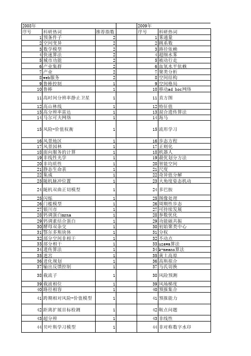
【国家自然科学基金】_空间依赖_基金支持热词逐年推荐_【万方软件创新助手】_20140731
107 108 109 110 111 112 113 114 115 116 117 118 119 120 121 122 123 124 125 126 127 128 129 130 131 132 133 134 135 136 137 138 139 140 141 142 143 144 145 146 147 148 149 150 151 152 பைடு நூலகம்53 154 155 156 157 158 159 160
独立成分分析法 状态空间方程 特征bagging 物理光学 焦移 点格局分析 灌丛 激光物理 演变态势 滤波正则化 渠道自动化 混合流体 淮河流域农业区 消费者行为 海马 波达方向 波束形成 油液泄漏 水价 死区效应 正定 正交空时分组码(ostbc) 模式空间分布 模仿 概念格修复 概念格 植被类型 梯形 本征正交分解 服务发现 有限时域差分法 有限分发 有源滤波器 有效菲涅耳数 最大似然法 暗视觉 智能空间 晶界 普适计算 明视觉 时间常数 时间-概率权衡 时空格局 时空切换 时滞 无线传感器嘲络 旅游小城镇 方程组 新疆 斑图 数理 数据依赖 数字版权管理 故障监测
衰落信道 表层土壤含水量 行星际磁场 血细胞 蟠变 蛋白质 虚拟现实建模语言 虚拟现实 蒸散 航空影像 自适应滤波 自然选择 自动优化 自主导航 脉冲星 背景灰度 聚类的离群 耦合时滞 耗散性 结构特点 经济增长 组织表达 组合导航系统 线性矩阵不等式 纹理分类 约束满足问题 粒子滤波 等离子体片 第二类nédélec棱有限元 第二类n6d6lec棱有限元 第一类nédélec二次棱有限元 空间表征 空间离群 空间电压矢量脉宽调制(svpwm) 空间点格局 空间数据中心 空时分组编码 移动自组网 移动机器人 秩序 种群生态 种子扩散 磁通量绳 磁尾 确定别名 石油 短命植物 知识可达性 皮层损害 电离层不均匀结构 电磁光束 生物功能 生存分析 环腺苷酸反应元件结合蛋白mrna
通信专业英文缩写名称简介
通信专业英文缩略语缩略语英语解释中文解释AAM/CMAdministrationModule/Communication Module管理和通信模块BBA BCCH Allocation BCCH分配BAM Back Administration Module后管理模块BCC BTS? Color Code基站色码BCCH Broadcast Control CHannel广播控制信道BCHBroadcast channel (transportchannel)广播信道(传输信道)BIE Base Station Interface Equipment基站接口设备BITSBuilding Integrated TimingSupply 大楼综合定时供给系统BM Basic Module基本模块BS Base Station基站BS1Abis Interface Abis接口BSC Base Station Controller基站控制器BSIU Base Station Interface Unit基站接口单元BSS Base Station Subsystem基站子系统BTS Base Transceiver Station基站收发信台CCA Cell Allocation小区分配CBCH Cell Broadcast Channel小区广播信道CC Country Code国家码CCCH Common Control Channel公共控制信道CCS Common Channel Signaling共路信令方式CDU Combiner and Divider Unit合分路单元CGI Cell Global Identification全球小区识别码CIC Circuit Identification Code电路识别码CRC Cyclic Redundancy Check循环冗余校验CS-1Code Scheme-1编码模式-1(s)CS-2Code Scheme-2编码模式-2(s)CS-3Code Scheme-3编码模式-3(s)CS-4Code Scheme-4编码模式-4(s)CTN Central Switching Network Board中央交换网板DDBF Database File数据库文件Destination (Signaling) Point目的信令点编码DPCCodeDRX Discontinuous Reception非连续接收DTX Discontinuous Transmission非连续性发射EE3M E3 Sub-Multiplexer E3子复用设备EAC External Alarm Collection外部告警采集ECSC Early Classmark Sending Control早期类标发送控制EDU Enhanced Duplexer Unit增强型双工单元增强型全速率语音编EFR Enhanced full rate speech code解码EST Establishment建立FFACCH Fast Associated Control Channel快速随路控制信道FBC Photoelectric Conversion Board光电转换板FBI Optical Fiber Interface Board光接口板FPU Frame Processing Unit帧处理单元全速率码变换器、全FTC Full Rate Transcoder速率变码器FTP File Transfer Protocol文件传输协议FUL Radio Signaling Link无线信令链路GGALM Alarm board告警板GCKS Clock source时钟板GCTN Central switching Network board中心交换网板GEMA Emergency Action board双机倒换板GFBI Fiber Interface board光纤接口板GLAP LAPD Protocol Process board LAPD协议处理板Inter-Module CommunicationGMC2模块通信板board,Module Communication and Control模块通信控制板GMCCboardGMEM Memory board数据库接口板GMPU Main Process Unit主处理单元GNET Switching Network board交换网板GNOD Node Communication Board节点通信板GOPT Local Optical Interface Board光纤通信板GPRS General Packet Radio Service通用分组无线业务GPS Global Position System全球定位系统Global System for MobileGSM全球移动通信系统CommunicationsGSM Signaling Switching Network信令交换网板GSNTBoardHHDLC High-level Data Link Control高级数据链路控制HO Handover切换High magnification Power高增益功放板HPAAmplifier boardHSN Hopping Sequence Number跳频序列号HW Highway母线IID IDentification/IDentity识别IND Indication指示IOMUiSite Operation and MaintenanceUnit操作维护单元板IP Internet Protocol互联网协议、网际协议LLAPDLink Access Protocol on theD-channel D信道上的链路访问协议LPN7Common Channel SignalingProcessing Board公共信道信令处理板MMA Mobile Allocation移动台(频率)分配MAIO Mobile Allocation Index Offset移动分配索引偏移MCC Mobile Country Code移动国家码MCK Main Clock board主时钟板MFU Microcell Frame Unit微蜂窝帧处理单元Multiplication and Management复用管理单元MMUUnit移动网编号、移动网MNC Mobile Network Code编码MS Mobile Station移动台(手机)MSC Mobile Switching Center移动交换中心MSM MSC Subrate channel Multiplexer MSC侧子复用板MTP Message Transfer Part消息传递部分NNCC Network Color Code网络色码NSS Network SubSystem网络子系统OOM Opration and Maintenance操作维护OMC Operation and MaintenanceCenter操作维护中心OML Operation and Maintenance Link操作与维护链路OMU Operation and Maintenance Unit操作维护单元OPC Originating Point Code源信令点编码PPb Pb Interface Pb接口PBCCH Packet Broadcast Control Channel分组广播控制信道PBGT Power Budget功率预算PBU Power Boost Unit功率增强单元PCCCH Packet Common Control Channel分组公共控制信道PCIC Packet Circuit Identity Code分组电路标识码PCM Pulse-Code Modulation脉冲编码调制PCU Packet Control Unit分组控制单元Plesiochronous? DigitalPDH准同步数字系列HierarchyPDTCH Packet Data Traffic Channel分组业务数据信道公用陆地移动(通信)PLMN Public Land Mobile Network网Power and Environment MonitoringPMU电源环境监测板UnitPSU Power Supply Unit供电单元PWC Secondary Power Supply Board二次电源板RRACH Random Access CHannel随机接入信道RSL Radio Signaling Link无线信令链路SSACCH Slow Associated Control Channel慢速随路控制信道SAPI Service Access Point Identifier业务接入点标识Signaling Connection Control信令连接控制部分SCCPPartSCU Simple Combiner Unit简单合路单元Stand-alone Dedicated ControlSDCCH独立专用控制信道ChannelSITE Site站点SM Sub-Multiplexer Interface子复用板Short Message Service CellSMBCB短消息业务小区广播BroadcastSMI Sub-Multiplexer Interface 子复用板SP Signaling Point信令点SS7Signaling System Number 7七号信令STP Signaling Transfer Point信令转接点TTA Timing Advance时间提前量TC Transcoder码变换器TCH Traffic CHannel业务信道TCSM Transcoder and Sub-Multiplexer码变换与子复用单元(器)TEI Terminal Equipment Identifier终端设备标识Transmission Extension powerTES传输扩展供电单元Supply unitTEU Transmission Extension Unit传输扩展单元TFO Tandem Free Operation免汇接运营Timing/Transmission and定时/传输管理单元TMUManagement Unit码变换器/速率适配TRAU Transcoder & Rate Adaptation Unit单元TRX Transceiver收发信机TS Timeslot时隙TSC Training Sequence Code训练系列号(编码)VVSWR Voltage Standing Wave Ratio电压驻波比WWS Workstation操作台?A, Asub A-interface A接口AC Alternating Current 交流AC Access Class (C0 to C15) 接入级别(C0到C15)ACCH Associated Control Channel 随路控制信道ACELP Algebraic code excitation linear prediction 代数码激励线性预测ACOM Antenna Combiner 天线合路器AGCH Access Grant Channel 接入允许信道AM/CM Administration Module/ Communication Module 管理和通信模块ANSI American National Standard Institute 美国国家标准组织APC Automatic Power Control 自动功率控制API Application Program Interface 应用程序接口APL Advanced Phase Locking 高级时钟锁相ARFCN Absolute Radio Frequency Channel Number 绝对射频信道号ASIC Application Specific Integrated Circuit 专用集成电路AuC Authentication Center 鉴权中心BBA BCCH Allocation BCCH分配BAM Back Administration Module 后管理模块BCC BTS Color Code 基站色码BCCH Broadcast Control CHannel 广播控制信道BCF Base Control Function 基本控制功能BCH Broadcast channel (transport channel) 广播信道BER Bit Error Rate 误码率BHCA Busy Hour Call Attempt 忙时尝试呼叫BIE Base station Interface Equipment (board) 基站接口设备(板)BIOS Basic Input Output System 基本输入输出系统BITS Building Integrated Timing Supply 大楼综合定时供给系统BM Basic Module 基本模块BP Burst Pulse 突发脉冲BQ Bad Quality 质量差BS Base Station 基站BS1 Abis Interface Abis接口BSC Base Station Controller 基站控制器BSIC Base Station Identity Code 基站识别码BSMU Base Station Interface Unit 基站接口单元BSS Base Station Subsystem 基站子系统BSSAP Base Station Subsystem Application Part 基站子系统应用部分BSSGP Base Station Subsystem GPRS Protocol 基站系统GPRS协议BSSMAP Base Station Subsystem Management Application Part 基站子系统管理应用部分BSSOMAP Base Station Subsystem Operation and Maintenance Application Part 基站子系统操作与维护应用部分BTS Base Transceiver Station 基站收发信台BTSM Base Transceiver Station Management BTS管理BVC BSSGP Virtual Connection BSSGP虚拟连接CCA Cell Allocation 小区分配CAMEL Customized Applications for Mobile network Enhanced Logic 移动网络增强逻辑的客户化应用CBA Cell Bar Access 小区禁止接入CBC Cell Broadcast Center 小区广播中心CBCH Cell Broadcast CHannel 小区广播信道CBCCH Cell Broadcast Control Channel 小区广播控制信道CBQ Cell Bar Qualify 小区禁止限制CBSM Cell Broadcast Short Message 小区广播短消息CC Country Code 国家码CC Calling Control 呼叫控制CC Connection Confirm 呼叫控制CCB Call Control Block 呼叫控制块CCBS Completion of Calls to Busy Subscribers 遇忙回呼CCCH Common Control Channel 公共控制信道CCH Control Channel 控制信道CCS Common Channel Signaling 共路信令方式CD Call Deflection 呼叫偏移CDB Cell Broadcast Database 小区广播数据库CDU Combining and Distribution Unit 合分路单元CELP Code Excited Linear Prediction 码激励线性预测CGI Cell Global Identity 小区全球识别码CI Cell Identity 小区识别CIC Circuit Identify Code 电路识别码CIC Carrier Interface Controller board 载频接口控制器CIR Carrier to Interference Ratio 载干比CKSN Ciphering Key Sequence Number 密钥序列号CKV Clock Drive board 时钟驱动板CM Connection Management 接续管理CPU Central Processing Unit 中央处理单元CR Connection Request 连接请求CRC Cyclic Redundancy Check 循环冗余校验CRO Cell Reselect Offset 小区重选偏移CS Coding Scheme (信道)编码方式CS-1 Code Scheme-1 编码模式-1(s)CS-2 Code Scheme-2 编码模式-2(s)CS-3 Code Scheme-3 编码模式-3(s)CS-4 Code Scheme-4 编码模式-4(s)CTN Central Switching Network Board 中央交换网板DDB DataBase 数据库DBF Database File 数据库文件DBMS Database Management System 数据库管理系统DC Direct Current 直流DCCH Dedicated Control Channel 专用控制信道DCL Diagnostic Control Link 诊断控制链路DDN Digital Data Network 数字数据网DL Downlink 下行链路DLC Data Link Connection 数据链路连接DLCEP Data Link Connection End Point 数据链路连接端点DLCEPI Data Link Connection End Point Identifier 数据链路连接端点标识DLCI Digital Link Connection Identity 数据链路连接标识DNS Domain Name Server 域名服务器DPC Destination (Signaling) Point Code 目的信令点编码DRDBMS Distributed Relational DBMS 分布式关系数据库管理系统DRX Discontinuous Reception (mechanism) 不连续接收DSC Downlink Signaling fault Count 下行信令故障计数DSP Digital Signal Processor 数字信号处理器DTAP Direct Transfer Application Part 直接传输应用部分DTMF Dual Tone Multi-frequency 双音多频(收号器)DTX Discontinuous transmission (mechanism) 不连续发送(机制)EE-Abis Enhanced Abis 增强型AbisE3M E3 Sub-Multiplexer 增强型E1子复用设备EA Early Allocation 预分配EAC External Alarm Collection 外部告警采集EC Emergency Call 紧急呼叫ECSC Early Classmark Sending Control 早期类标发送控制ECT Explicit Call Transfer 显示呼叫转移EDU Enhanced Duplexer Unit 增强型双工单元EFR Enhanced full rate speech code 增强型全速率语音编解码EIR Equipment Identity Register 设备识别寄存器EM Extended Measurement 扩展测量EMC Electromagnetic Compatibility 电磁兼容性EST Establishment 建立ETS European Telecommunication Standard 欧洲电信标准ETSI European Telecommunication Standard Institute 欧洲电信标准组织FFACCH Fast Associated Control CHannel 快速随路控制信道FBC Photoelectric Conversion Board 光电转换板FBI Optical Fiber Interface Board 光接口板FCCH Frequency Correction CHannel 频率校正信道FCS Frame Check Sequence 帧校验序列FDMA Frequency Division Multiple Access 频分多址FH Frequency Hopping 跳频FIR Finity Impulsion Response 有限冲击响应FN Frame Number 帧号FPU Frame Processing Unit 帧处理单元FR Frame Relay 帧中继FTAM File Transfer Access and manipulation 文件传输、接入及使用FTC Full Rate Transcoder 码变换板FTP File Transfer Protocol 全速率码变换器FUC Frame Unit Controller 帧单元控制器FUL Radio Signaling Link 无线信令链路GG-Abis GPRS Abis GPRS AbisGALM Alarm board 告警板GCKS Clock source 时钟板GCTN Central switching Network board 中心交换网板GEMA Emergency Message Automatic Transmission System 双机倒换板GFBI Fiber Interface board 光纤接口板GGSN Gateway GPRS Support Node 网关GPRS支持节点GLAP LAPD Protocol Process board LAPD协议处理板GMC2 Inter-Module Communication board 模块通信板GMCC Module Communication and Control board 模块通信控制板GMEM Memory board 数据库接口板GMM GPRS Mobility Management GPRS移动性管理GMPU Main Processing Unit 主处理单元GMSC Gateway Mobile Switching Center 关口局GMSK Gaussian Minimum Shift-frequency Keying 高斯滤波最小移频键控GNET Intra-module switching network board 交换网板GNOD Node Communication Board 节点通信板GOPT Local Optical Interface Board 光纤通信板GPRS General Packet Radio Service 通用分组无线业务GPS Global Position System 全球定位系统GPWS GSM Secondary Power board 二次电源板GSM, GSM900, GSM1800 Global System for Mobile communications 全球移动通信系统,900MHz的GSM系统,1800MHz的GSM系统GSN GPRS Support Node GPRS支持节点GSNT GSM Signaling Switching Network Board 信令交换网板GT Global Title 全局码GTP GPRS Tunnelling Protocol GPRS隧道协议HHC/HY COM Hybrid Combiner 混合桥型合路器HCS Hierarchical Cell Structure 小区分层结构HDLC High level Data Link Control 高级数据链路控制HDSL High speed Digital Subscriber Line 高速数字用户线HLR Home Location Register 归属位置寄存器HO Handover 切换HPA High magnification Power Amplifier board 高增益功放板HSC Hot Swap Controller 热倒换控制器HSN Hopping Sequence Number 跳频序列号HW Highway 高速通路IID IDentification/IDentity 识别IEC International Electrotechnical Commission 国际电工委员会IMEI International Mobile station Equipment Identity 国际移动终端设备标识IMSI International Mobile Station Identity 国际移动用户识别码IND Indication 指示IOMU iSite Operation and Maintenance Unit 操作维护单元板IP Internet Protocol 互联网协议ISDN Integrated Services Digital Network 综合业务数字网ISO International Standard Organization 国际标准化组织ISR Interrupt Service 中断服务程序ISUP Integrated Services Digital Network User Part/ISDN User Part (七号信令之)ISDN用户部分ITU International Telecommunication Union 国际电信联盟ITU-T International Telecommunication Union - Telecommunication Standardization Sector 国际电信联盟-电信标准部IWF Inter-working Function 互连功能J- -KLL2ML Layer 2 Management Link 层2管理链路L3MM Layer-3 Mobility Management 层三移动管理LA Location Area 位置区LAC Location Area Code 位置区码(LAC)LAI Location Area Identity 位置区标识LAP Link Access Protocol 协议处理板LAPD Link Access Protocol on the D-channel D信道上的链路访问协议LAPDMAIL LAPD Mail Box LAPD邮箱LAPDm Link Access Protocol on the Dm channel Dm信道上的链路访问协议LLC Logical Link Control 逻辑链路控制LMT Local Maintenance Terminal 本地维护终端LNA Low Noise Amplifier 低噪声放大器LPN7 Common Channel Signaling Processing Board 公共信道信令处理板MMA Mobile Allocation 移动台(频率)分配MAC Media Access Control 媒质接入控制MAIO Mobile Allocation Index Offset 移动分配索引偏移MAP Mobile Application Part 移动应用部分MBR Multiband Report 多频报告MCC Mobile Country Code 移动国家码MCK Main ClocK board 主时钟板MCP Multiple Communication-Protocol Processor 多重通信协议处理器MDC Message Discrimination 消息鉴别MDSL Medium Bit-rate Digital Subscriber Loop 中速数字用户环线MDT Message Distribution 消息分配ME Mobile Equipment 移动设备MFU Microcell Frame Unit 微蜂窝帧处理单元MM Mobility Management 移动性管理MMU Multiplication and Management Unit 复用管理单元MNC Mobile Network Code 移动网号MNS Mobile Network Signaling 移动网信令MR Measurement Result 测量结果MR Measurement Report 测量报告MRP Multiple Reuse Pattern 多重复用方式MRT Message Routing 消息路由MS Mobile Station 测量报告MSC Mobile services Switching Centre, Mobile Switching Centre 移动交换中心MSISDN Mobile Station International ISDN Number 移动台国际ISDN 号码MSM MSC Subrate channel Multiplexer MSC侧子复用板MT Mobile Terminal 移动终端MTBF Mean Time Between Failure 平均无故障时间MTP Message Transfer Part 消息传输部分NNC Network Control 网络控制NCC Network Color Code 网络色码NCH Notification Channel 通知信道NE Network Equipment 网络设备NM Network Management 网络管理NS Network Service 网络服务NSE Network Service Entity 网络服务实体NSS Network SubSystem 网络子系统OO&M, OM Operations & Maintenance 操作与维护OACSO Off Air Call Set up 不占用空中通道的呼叫启动OAM Operation Administration and Maintenance 运行管理和维护OMAP Operation and Maintenance Application Part 操作维护应用部分OMC Operations & Maintenance Centre 操作维护中心OML Operation and Maintenance Link 操作与维护链路OMU Operations & Maintenance Unit (board) 操作维护单元(板)OOP Object Oriented Programming 面向对象的程序设计OPC Originating Point Code 源信令点编码OPT Optic Interface board 光纤通信板OS Operation System 操作系统OSI Open System Interconnection 开放系统互连模型PPA Power Amplifier 功率放大器PAGCH Packet Access Grant Channel 分组接入允许信道PBCCH Packet Broadcast Control Channel 分组广播控制信道PBGT Power Budget 功率预算PBU Power Boost Unit 功率增强单元Pb Pb Interface Pb接口PbSL PCU-BSC Signaling Link PCU-BSC间信令链路PCCCH Packet Common Control Channel 分组公共控制信道PCH Paging CHannel 寻呼信道PCIC Packet Circuit Identity Code 分组电路标识码PCM Pulse-Code Modulation 脉冲编码调制PCU Packet Control Unit 分组控制单元PD Protocol Discrimination 协议识别码PDCH Packet Data Channel 分组数据信道PDH Plesiochronous Digital Hierarchy 准同步数字系列PDN Packet Data Network 分组数据网PDP Packet Data Protocol 分组数据协议PDTCH Packet Data Traffic Channel 分组业务数据信道PI Peripheral Interface 外设接口部件PIN Personal Identity Number 个人识别码PLL Phase Locked Loop 锁相环路PLMN Public Land Mobile Network 公用陆地移动网络PMU Power and Environment Monitoring Unit 电源环境监测板PNCH Packet Notification Channel 分组通知信道POMU Packet Operation & Maintenance Unit 分组操作维护单元PON Passive Optical Network 无源光网络PPCH Packet Paging Channel 分组寻呼信道PRACH Packet Random Access Channel 分组随机接入信道PSDN Public Switched Data Network 公用数据交换网PSI Packet System Information 分组系统消息PSK Phase Shift Keying 相移键控PSTN Public Switched Telephone Network 公用电话交换网PSU Power Supply Unit 供电单元PT Penalty Time 惩罚时间PTCCH Packet Timing advance Control Channel 分组定时提前控制信道PTM Point To Multipoint 点到多点PTM-M Point To Multipoint Multicast 点对多点广播PTM-SC Point to Multipoint Service Center 点到多点数据服务中心PTP Point To Point 点对点PWC Secondary Power Supply Board 电源控制板QQoS Quality of Service 业务质量RRACH Random Access Channel 随机接入信道RE Reestablishment 呼叫重建RF Radio Frequency 射频RLC Radio Link Control 无线链路控制RLM Radio Link Management 无线链路管理RPE-LTP Regular Pulse Excitation-Long Term Prediction 规则脉冲激励-长期预测RPPU Radio Packet Process Unit 无线分组处理单元RR Radio Resource 无线资源RSA Rivest-Shamir-Adleman 通用关键子密码方法RSL Radio Signaling Link 无线信令链路RTE Radio Test Equipment 天线测试设备RX Receiver/Reception 收信机/接收RXLEV Received signal level 接收信号等级RXQUAL Received Signal Quality 接收信号质量SSABM Set Asynchronous Balanced Mode 置异步平衡模式SACCH Slow Associated Control Channel 慢速随路控制信道SACCH/C4 Slow Associated Control Channel/SDCCH/4 慢速随路控制信道/SDCCH/4SACCH/C8 Slow Associated Control CHannel/SDCCH/8 慢速随路控制信道/SDCCH/8SACCH/T Slow Associated Control CHannel/Traffic channel 慢速随路控制信道/业务信道SACCH/TF Slow Associated Control Channel/Traffic channel Full rate 慢速随路控制信道/全速率业务信道SAP Service Access Point 服务接入点SAPI Service Access Point Identifier 业务接入点标识SCCP Signaling Connection Control Part 信令连接控制部分SCH Synchronization CHannel 同步信道SCMG SCCP Management SCCP管理SCU Simple combining Unit 简单合路单元SDCCH Stand-alone Dedicated Control CHannel 独立专用控制信道SDH Synchronous Digital Hierarchy 同步数字系列SDU Service Data Unit 业务数据单元SGSN Serving GPRS Support Node 服务GPRS支持节点SID Silence Descriptor 静噪指示SIG Signaling 信令SIM Subscriber Identity Module 用户识别卡SITE Site 站点SLM Signaling Link Management 信令链路管理SLS Signaling Link Selection 信令链路选择码SM Sub-Multiplexer Interface 子复用板SM-SC Short Message - Service Center 短消息中心SMBCB Short Message Service Cell Broadcast 短消息业务小区广播SMC Short Message Center 短消息中心SMI Sub-Multiplexer Interface 子复用板SMS Short Message Service 短消息业务SMS-GMSC Short Message Service - Gateway MSC 短消息关口MSC SMS-IWMSC Short Message Service Interworking MSC 短消息互联MSC SMSCB Short Message Service Cell Broadcast 短消息小区广播SMUX Sub-Multiplexer 子复用器SNDCP SubNetwork Dependent convergence Protocol 子网相关的收敛协议SOR Support Optimization Routing 支持优选路由SP Signaling Point 信令点SRM Signaling Route Management 信令路由管理SS Supplementary Service 补充业务SS7 Signalling System 七号信令SSN SubSystem Number 子系统号STM Signaling Traffic Management 信令业务管理STP Signaling Transfer Point 信令转接点TTA Timing Advance 定时提前量TAI Timing Advance Index 时间提前量索引TBF Temporary Block Flow 临时数据块流TC Transcoder 码变换器TCH Traffic Channel 业务信道TCH/F A full rate TCH 全速率业务信道TCH/F2.4 A full rate data TCH s) 全速率数据业务信道(s)TCH/F4.8 A full rate date TCH s) 全速率数据业务信道(s)TCH/F9.6 A full rate data TCH s) 全速率数据业务信道(s)TCH/FS A full rate Speech TCH 全速率话音业务信道TCI Terminal Interface board 终端接口板TCP Transmission Control Protocol 传输控制协议TCSM TransCoder & Sub-Multiplexer 码变换与子复用单元TDMA Time Division Multiple Access 时分多址TE Terminal Equipment 终端设备TEI Terminal Equipment Identifier 终端设备识别码TES Transmission Extension power Supply unit 传输扩展供电单元TEU Transmission Extension Unit 传输扩展单元TFI Transport Format Indicator 传输格式指示TFO Tandem Free Operation 免汇接运营TLLI Temporary Link Level Identity 临时链路等级标识TMSC Tandem Mobile Switching Centre 汇接移动交换中心TMSI Temporary Mobile Subscriber Identifier 临时移动用户标识符TMU Timing/Transmission and Management Unit 定时/传输管理单元TN Timeslot Number 时隙号TNI Terminal Network Interface 终端网络接口部件TO Temporary Offset 临时偏移TRAU Transcoder & Rate Adaptation Unit 码变换器/速率适配单元TRX Transceiver (board) 收发信机TS Timeslot 时隙TSC Training Sequence Code 训练系列号(编码)TUP Telephone User Part(SS7) 电话用户部分UUA Unnumbered Acknowledge 无编号证实UDP User Datagram Protocol 用户数据报协议UDT Unit Data 单位数据UI Unnumbered Information (frame) 无编号信息帧Um 空中接口USF Uplink State Flag 上行链路状态标识USSD Unstructured Supplementary Service Data 非结构化补充业务数据VVAD Voice Activity Detection 话音激活检测VBS Voice Broadcast Service 话音广播呼叫业务VEA Very Early Allocation 很早分配VGCS Voice Group Call Service 话音组呼业务VLR Visitor Location Register 拜访用户位置寄存器VM Voice Mailbox 语音邮箱VSAT Very Small Aperture Terminal 甚小天线卫星地球站WWDT Watchdog Timer 看门狗WS Workstation 操作台XxDSL x Digital Subscriber Line x数字用户线YZ爱尔兰表:某基站站型为S4/4/4。
PgvislCCNA认证基础-教学大纲
||生活|
一个人总要走陌生的路,看陌生的风景,听陌生的歌,然后在某个不经意的瞬间,你会发现,原本费尽心机想要忘记的事情真的就这么忘记了..
|-----郭敬明
Cisco
一、
(一)
思科网络技术学院项目(Cisco Networking Academy Program)是Cisco systems公司在全球范围内推出的一个主要面向初级网络工程技术人员的培训项目。本课程以Cisco网络学院CCNA课程的第一、二部分内容为主。主要讲述网络基本术语、模型、协议及Cisco路由器的基本操作,为全面学习CCNA认证课程打下一个良好的基础。
二、
第一
绪论
第一章
1.接入到互联网所需要的物理连接;
2.计算机的主要组成部件;
3.网卡及调制解调器的安装和故障排除;
4.网络连通性测试的基本步骤;
5.Web浏览器的配置和选择;
6.二进制;
7.二进制到十进制的转换;
8.十六进制;
9.IP地址及网络掩码的二进制表示;
10.IP地址及网络掩码的十进制表示。
9.广域网连接在实验室中的模拟
10.如何配置控制台(console)连接;
11.路由器内部组件的标记和描述;
12.路由器的物理特性;
13.路由器上的通用端口;
14.如何连接路由器的控制台端口、局域网端口和广域网端口。
第二章
1.建立超级终端会话;
2.登录到路由器;
3.在命令行界面下使用帮助功能;
4.对命令的错误进行故障排除;
14.常见的RIP配置问题
15.检验RIP的配置
16.RIP的故障排除
17.RIP的负载均衡
18.结合使用静态路由与RIP协议
华为5g网络优化工程师资格认证题库_导出版

A、FR1 频段在子载波间隔 SCS=15KHz 时.最大可用 RB 数目是 546 个 B、FR1 频段在子载波间隔 SCS=30KHz 时,最大可用 RB 数自是 270 个 C、FR2 在子载波间隔 SCS=60KHz 时,最大可用 RB 数目是 264 个 D、FR2 在子载波间隔 SCS=30KHz 时,最大可用 RB 数目是 528 个 答案:C 25.5G 小区中 UE 激活 BWP 带宽为 100RB,则相对应关联 CSI-RS 资源的最小 RB 数 是多少? A、32 B、24 C、100 D、64 答案:B 26.如果采用 32T32R,10OMHz 带宽,MU-MIMO8 流场景下,使用 ECPRI 接口所需要的 带宽是多少? A、25Gbps B、50gbps C、10gbps D、100gbps 答案:A 27.5G 协议规定了 gNodeB 支持多少个逻辑信道分组 A、4 B、8 C、12 D、16 答案:B 28.以下哪种 SCS 不允许用于 SSB? A、15KHz B、30KHz C、60KHz
1
A、1bit B、4bit C、2bit D、3bit 答案:C 6.以下信道或信号通常采用开环功控的是哪项? A、PRACH B、PUSCH C、PUCCH D、SRS 答案:A 7.以下哪个信号可以反映网络上行的覆盖﹖ A、CSI-RS B、SRS C、PDCCHDMRS D、PBCHDMRS 答案:B 8.以下关于华为 RAN3.1SA 小区上下文异常释放场景的描述,错误的是哪项? A、控制面不会被释放 B、依据信令携带的原因值判断是否为异常释放 C、可以由 gNodeB 或 AMF 触发 D、用户面会被释放 答案:A 9.以下哪条信令用于基站发起的释放 PDU 会话? A、PDUSessionResourceNotify B、PDUSessionResourceReleaseResponse C、PDUSessionResourceReleasemand D、UEContextReleasemand 答案:A
5G华为认证题库1000题

以下哪种NSA组网用户面的分流锚点在eNB侧()AA)Option3xB)Option3aC)Option3D)Option21个小区可以通过RRC信令给UE配置()个DL BWP。
BA)12B)4C)2D)85G核心网中,哪个网元的功能与LTE网络中MME的功能类似?()CA)PCFB)UPFC)AMFD)UDM5G网络中,最大的广播波束数量和频段相关,在sub 6G频段中,最大可使用的广播波束数量是多少个?()BA)64B)8C)3D)16在采用下列频谱来进行5G组网时,最可能出现上下行覆盖不平衡问题的是:()AA)3.3GHZB)1800MHzC)800MHzD)2.6GHz5G关于PDSCH资源映射的起始符号为{0,1,2,3},长度为3~14个符号,属于那种类型?()A)TypeDB)TypeBC)TypeAD)TypeC下列协议中,哪个协议可以用于5G NG-U接口进行用户面数据处理?BA)RRCB)GTP-UC)GTP-CD)TCP在5G R15版本中,可用于对用户数据进行信道编码的方案是:()CA)Polar码B)前向纠错码C)LDPC编码D)Turbo编码以下关于NR中PDSCH的DmRS说法错误的是?()DA)DMRS类型Type2:单符号最大支持6端口,双符号12端口B)Additional (Add)DMRS:额外DMRS,1~3符号,由高层参数UL-DMRS-add-pos配置有无和符号位置C)Front Loaded (FL)DMRS:前置DMRS,1~2符号,默认需要配置D)DMRS类型Type1:单符号最大支持4端口,双符号6端口5G空口中,控制面协议栈不包含以下哪个协议?()DA)RLCB)PDCPC)RRCD)SDAPE)E、MAC采用相同频段,在经过不同障碍物或介质时,会有不同的损耗效果,在下列覆盖场景中,mmWave穿透相同厚度的介质损耗最大的是:()AA)三合板门B)玻璃门窗C)水泥墙D)木门5G网络中给,PRACH信道长序列格式中的前导码格式共有几种()CA)6B)9C)4D)13下列信道中,属于逻辑信道的是:()DA)PBCHB)UL-SCHC)DL-SCHD)BCCH目前中国移动在5G网络中2.6G频段采用的时隙配置为()AA)8:2B)7:3C)4:1D)3:15G高频场景中,为了进行下行相位噪声跟踪和补偿,可能使用到的参考信号是:()AA)PT-RSB)SRSC)DMRSD)CSI-RS在5G网络中,当小区SCS参数μ取值为2时,下列关于时隙的说法,正确的是哪一个。
LTE英文名词缩写集锦

CDN CEPT CFI CFN CID CID CIF CMAS CMC CN CP CP CPICH CPICH Ec/No C-plane CQI CRC C-RNTI CRS CS CSFB CSG CSI CSI-IM CW DAI DC DCCH DCI DFT DFTS DiffServ DL DL DL-SCH DM-RS DPCCH DPCH DRB DRX DTCH DTT DTX DUT DwPTS E EAB EARFCN ECC ECCE
缩写 1xRTT AC AC ACI ACIR ACK ACL ACLR ACP ACRR ACS aGW AM AMBR AMC AMD AMN A-MPR ANR AP ARQ AS ASN.1 ATT AWGN B BCCH BCD BCH BPSK BS BSIC BSR BSS BTS BW C/I CA CACLR CAZAC CCCH CCCH SDU CCE CCO CCTrCH CDD CDF CDMA
全称 CDMA2000 1x Radio Transmission Technology Alternating Current Access Class (of the USIM) Adjacent Channel Interference Adjacent Channel Interference Ratio Acknowledgement (in HARQ protocols) Adjacent Channel Leakage Adjacent Channel Leakage power Ratio Adjacent Channel Power Adjacent Channel Rejection Ratio Adjacent Channel Selectivity E-UTRAN Access Gateway Acknowledged Mode Aggregate Maximum Bit Rate Adaptive Modulation and Coding AM Data Artificial Mains Network Additional Maximum Power Reduction Automatic Neighbour Relation Application Protocol Automatic Repeat Request Access Stratum Abstract Syntax Notation One Attenuator Additive White Gaussian Noise Bottom RF channel (for testing purposes) Broadcast Control Channel Binary Coded Decimal Broadcast Channel Binary Phase Shift Keying Base Station Base transceiver Station Identity Code Buffer Status Report Base Station System Base Transceiver Station Bandwidth Carrier-to-Interference Power Ratio Carrier Aggregation Cumulative ACLR Constant Amplitude Zero Auto-Correlation Common Control CHannel Common Control Channel SDU Control Channel Element Cell Change Order Coded Composite Transport Channel Cyclic delay diversity Cumulative Distribution Function Code Division Multiple Access
2021年CCNA笔记 EIGRP AND OSPF(一)

CCNA笔记 EIGRP and OSPF(一)Enhan ___d IGRP(EIGRP) and Open Shortest Path First(OSPF)EIGRP Features and OperationEIGRP是1种无分类(classless),增强的距离向量路由协议,和IGRP类似,EIGRP也使用AS,但是和IGRP不同的是,EIGRP在它的路由更新信息中要包含子网掩码的信息.这样,在我们设计的网络的时候,就允许我们使用VL ___和sum ___rization.EIGRP有时候也算是混合型路由协议,因为它同时具有了距离向量路和链路状态的一些特征:比如它不像OSPF那样发送链路状态包而发送传统的距离向量更新;EIGRP也有链路状态协议的特征比如它在相邻router启动的时候同步路由表,然后只在拓扑结构发生变化的时候发送1些更新.这样就使得EIGRP能够很好的在1个大型网络中工作.EIGRP支持的跳数多达255.EIGRP的主要特点如下: 1.通过PDMs(Protocol-Dependent Module)来支持IP,IPX和AppleTalk 2.有效的邻router的发现 3.通过可靠传输协议(Reliable Transport Protocol,RTP)进行通讯 4.通过扩散更新算法(Diffusing Update Algorithm,DUAL)来选择最佳路径Protocol-Dependent ModuleEIGRP的1大特点是它可以支持几种网络层协议:IP,IPX和AppleTalk等.能像EIGRP那样支持数种网络层协议的还有Intermediate System-to-Intermediate System(IS-IS)协议,但是这个协议只支持IP和Connectionless Network Servi___(CLNS).EIGRP通过PDMs来支持不同的网络层协议.每个EIGRP 的PDM保持1个单独的路由信息表来装载某种协议(比如IP)的路由信息.也就是有IP/EIGRP表,IPX/EIGRP的表和AppleTalk/EIGRP表Neighbor Discovery在运行了EIGRP的router彼此进行交换信息之前,它们首先必须成为邻居(neighbor).建立邻居关系必须满足以下3个条件:1.Hello信息或接受收ACK2.AS号匹配3.K值链路状态协议趋向于使用Hello信息来建立邻居关系,它不会像距离向量那样周期性的发送路由更新.为了保持邻居关系,运行了EIGRP的router必须持续从邻居那里收到Hellos如果不在1个AS内,router之间是不会共享路由信息的,也不会建立邻居关系.这样做的优点是在大型网络中可以减少特定某个AS 内路由信息的传播当EIGRP发现新邻居的时候,就开始通告整个路由表给别的router,当所有的router都知道新成员的加入,学习到新的路径以后,从那开始,路由表中有变动的部分才会传播给别的router.当router接收到邻居的更新以后,把它们保存在本地数据库表里看下几个术语: 1.可行距离(feasible distan ___):到达一个目的地的最短路由的度 2.后继(suessor):后继是一个直接连接的邻居router,通过它具有到达目的地的最短路由.通过后继router 将包转发到目的地 3.通告距离(reported distan ___):相邻router所通告的相邻router自己到达某个目的地的最短路由的度4.可行后继(feasible suessor):可行后继是一个邻居router,通过它可以到达目的地,不使用这个router是因为通过它到达目的地的路由的度比其他router高,但它的通告距离小于可行距离,因而被保存在拓扑表中,用做备择路由Reliable Transport Protocol(RTP)EIGRP使用一种叫做RTP的私有协议,来管理使用了EIGRP的router之间的通信,如RTP的名字,可靠(reliable)即为这个协议的关键.RTP负责EIGRP数据包到所有邻居的有保证和按顺序的传输.它支持多目组播或单点传送数据包的混合传输/出于对效率的考虑.只有某些E IGRP数据包被保证可靠传输.RTP确保在相邻router间正在进行的通信能够被维持.因此,它为邻居维护了一张重传表.该表指示还没有被邻居确认的数据包.未确认的可靠数据包最多可以被重传1 6次或直到保持时间超时,以它们当中时间更长的那个为限.EIGRP所使用的多目组播地址是224.0.0.10Diffusing Update Algorithm(DUAL)EIGRP使用DUAL来选择和保持到远端的最佳路径.它能使router 判决某邻居通告的一个路径是否处于循环状态,并允许router找到替代路径而无须等待其他router的更新.这样做有助于加快网络的汇聚.这个算法顾及以下几点: 1.备份的路由线路 2.支持VL ___ 3.动态路由恢复 4.没有发现线路的话发送查询寻找新路线Using EIGRP to Support Large NetworksEIGRP在大型网络中能够工作的很好,包含了很多优点比如: 1.在1个单独的router上可以支持多个AS 2.支持VL ___和sum ___rization 3.路由发现和保持Multiple AS只有AS号相同的router才能共享路由信息.把大型网络分成不同的AS,可以有效的加快汇聚.EIGRP的AD为90,而外部EIGRP(external EIGRP)的AD为170VL ___ Support and Sum ___rization之前说过EIGRP支持VL ___,也支持不连续子网.什么是不连续子网?,如下图:如图可以看到,2个子网172.16.10.0/24和172.16.20.0/24由10.3.1.0/24来连接,但是routerA和B认为它们只有网络172.16.0.0EIGRP支持在任何运行EIGRP的router上sum ___ry的手动创建,这样可以减少路由表的体积.EIGRP自动把网络sum ___rize到等级边界,如下图:Route Discovery and Maintenan ___ 类似一些链路状态的协议,EIGRP通过Hello信息来发现邻居;而它又和距离向量类似,使用传闻路由的机制,即不主动去发现,而是听从别人的信息.EIGRP使用一系列的表来存储信息: 1.邻居表,记录了邻居的一些信息 2.拓扑表,记录了网络中的拓扑状态 3.路由表,根据这个来做路由决定EIGRP MetricsEIGRP使用混合度,包含到4个方面: 1.带宽 2.延迟(delay) 3.负载(load) 4.可靠性(reliability) 5.最大传输单元( ___ximum tran ___ission unix,MTU)默认情况下EIGRP使用带宽和延迟来决定最佳路径Configuration EIGRP配置EIGRP,首先在全局配置模式下使用router eigrp [AS号]命令.接下来再使用work命令定义直接相连的网络.仍然可以像配置IGRP那样使用passive-inte ___ ___命令来禁止某个接口接收或发送Hello信息.并且记住EIGRP的AD是90来看1个配置实例,如图:Router Network Address Inte ___ ___ Address RouterA192.168.10.0 fa0/0 192.168.10.1 192.168.20.0 s0/0192.168.20.1 RouterB 192.168.20.0 s0/0 192.168.20.2 192.168.40.0 s0/1 192.168.40.1 192.168.30.0 fa0/0 192.168.30.1 RouterC 192.168.40.0 s0/0 192.168.40.2 192.168.50.0 fa0/0 192.168.50.1 配置RouterA:RouterA(config)#router eigrp 10 RouterA(config-router)#work 192.168.10.0 RouterA(config-router)#work 192.168.20.0 RouterA(config-router)#^Z RouterA# 记住配置EIGRP和配置IGRP十分类似,唯一不同的是EIGRP是无分类路由(classless routing)配置RouterB: RouterB(config)#router eigrp 10RouterB(config-router)#work 192.168.20.0 RouterB(config-router)#work 192.168.30.0 RouterB(config-router)#work 192.168.40.0 RouterB(config-router)#^Z RouterB#配置RouterC: RouterC(config)#router eigrp 10RouterC(config-router)#work 192.168.40.0 RouterC(config-router)#work 192.168.50.0 RouterC(config-router)#^Z RouterC#这样配置看上去好象没什么问题,EIGRP的AD比之前配置的RIPv1和IGRP的低,但是有个问题就是:增加了CPU的负担,而且占用了额外的带宽还有1点要注意的是自动sum ___rization,router默认会向分级边界进行sum ___rize.如下图:A的配置如下: A(config)#router eigrp 100 A(config-router)#w 172.16.0.0 A(config-router)#w 10.0.0.0A(config-router)#no auto-sum ___ryB的配置如下: B(config)#router eigrp 100 B(config-router)#w 172.16.0.0 B(config-router)#w 10.0.0.0B(config-router)#no auto-sum ___ry 使用no auto-sum ___ry 命令后,运行了EIGRP的router就不会相互进行通告Verifying EIGRP在刚才配置好的情况下使用show ip route命令查看路由信息,如下: RouterA#sh ip route (略) D 192.168.30.0/24[90/2172416] via 192.168.20.2, 00:04:36, Serial0/0 (略) 注意字母D代表DUAL,即代表EIGRP,AD为90show ip route eigrp命令只显示路由表中的EIGRP选项show ip eigrp neighbors:显示所有的EIGRP邻居show ip eigrp topology:显示EIGRP拓扑表条目,如下: RouterC#sh ip eigrp topology (略) P 192.168.40.0/24, 1 suessors, FD is 21469856 Via Connected, Serial0 (略) 注意前面的P代表passive状态,这样的状态是正常的如果看见的是A即active状态而不是P,说明router失去了到这个网络的路径并且在寻找替代路径Open Shortest Path First(OSPF) Basics在1个大型网络中,假如不是所有的设备都是Cisco的,EIGRP明显就不行,因为它是私有的.所以就可以使用OSPF协议或者路由redistribution(路由协议之间的翻译服务).OSPF使用Dijkstra算法,是1种链路状态协议.OSPF汇聚快速,支持多个耗费相同的路径.和EIGRP不同的是,OSPF只支持IP路由.OSPF也能够设计网络为层次化的,这样就把1个大的网络分割成几个小的网络,叫做区域(area).这是OSPF最好的设计方法.把OSPF设计成层次化的好处是:1.减少路由成本(overhead)2.加速汇聚3.把大网络分割成小的区域下面是1个典型的OSPF设计图,如下:注意这个图,BR为骨干router(backbone router,BR),连接到这个骨干的为区域0或者骨干区域(backbone area),OSPF必须要有个区域0所有的router应该尽可能的连接到这个区域.连接其他区域到骨干区域的为区域边界router(area border router,ABR),ABR必须至少有1个接口位于区域0中.OSPF运行在1个AS中,而且能够连接多个AS,连接多个AS的router为自治系统边界router(autonomous system boundary router,ASBR)模板,内容仅供参考。
CCNA(Stand-ALONE)Lab 25-Frame Relay Hub-and-Spoke Topology

CCNA(Stand-ALONE)Lab 25-Frame Relay Hub-and-Spoke Topology Objective:Learn to configure a hub-and-spoke topology.Lab Equipment:Router 1, Router 2, Router 3, and Router 4 fro m the eRouters menuBackground Reading:Lab Primer Lesson 9: Frame RelayYour co mpany’s corporate office is in Dallas, and its sales offices are in San Francisco, New York,and Tampa. You want to impleme nt a hub-and-spoke topology in which all of the sales offices con nect to the corporate office to send all data, including communica tions between sales offices.1. First, assign the host names of Dallas, San_Francisco, New_Yo rk, and Tampa to Router 1, Router 2, Router 3, and Router 4, re spectively.Dallas:San_Francisco:New_York:Tampa:2. Now, enter interface configuration mode for the serial 0 interfa ce on Dallas, and set the encapsulation type to Frame Relay. Be sure to enable the interface.Dallas(config)#interface serial 0Dallas(config-if)#encapsulation frame-relayDallas(config-if)#no shutdown3. Next, create a subinterface for the connection from Dallas to t he San Francisco sales office.Dallas(config-if)#exitDallas(config)#interface serial 0.100 point-to-pointDallas(config-subif)#4. Assign the subinterface the DLCI number for the connection fr om Dallas to San_Francisco, and configure the subinterface with t he appropriate IP address. Remember to enable the subinterface. Dallas(config-subif)#frame-relay interface-dlci 102Dallas(config-subif)#ip address 172.16.1.1 255.255.255.0Dallas(config-subif)#no shutdown5. Create a subinterface for the connection from Dallas to the sal es office in New York.Dallas(config-subif)#exitDallas(config)#interface serial 0.200 point-to-pointDallas(config-subif)#6. Add the correct DLCI for the connection from Dallas to New_Y ork, and configure the appropriate IP address for the subinterface. Remember to enable the subinterface.Dallas(config-subif)#frame-relay interface-dlci 103Dallas(config-subif)#ip address 172.16.2.1 255.255.255.0Dallas(config-subif)#no shutdown7. Create a subinterface for the connection from Dallas to the sal es office in Tampa.Dallas(config-subif)#exitDallas(config)#interface serial 0.300 point-to-pointDallas(config-subif)#8. Add the correct DLCI for the Dallas to Tampa connection, and configure the appropriate IP address for the subinterface. Remem ber to enable the subinterface.Dallas(config-subif)#frame-relay interface-dlci 104Dallas(config-subif)#ip address 172.16.3.1 255.255.255.0Dallas(config-subif)#no shutdown9. Access the serial 0 interface on San_Francisco, set the encaps ulation to Frame Relay,and enable the interface.San_Francisco(config)#interface serial 0San_Francisco(config-if)#encapsulation frame-relaySan_Francisco(config-if)#no shutdown10. Because subinterfaces are not necessary for single connection s, add the appropriate DLCI value.San_Francisco(config-if)#frame-relay interface-dlci 20111. Set the IP address for this interface, and enable the interface. San_Francisco(config-if)#ip address 172.16.1.2 255.255.255.0 San_Francisco(config-if)# no shutdown12. Access the serial 0 interface on New_York, and set the encap sulation to Frame Relay.New_York(config)#interface serial 0New_York(config-if)#encapsulation frame-relay13. Add the appropriate DLCI value.New_York(config-if)#frame-relay interface-dlci 30114. Set the IP address for this interface, and enable the interface. New_York(config-if)#ip address 172.16.2.2 255.255.255.0New_York(config-if)#no shutdown15. Access the serial 0 interface on Tampa, and set the encapsul ation to Frame Relay.Tampa(config)#interface serial 0Tampa(config-if)#encapsulation frame-relay16. Add the appropriate DLCI value.Tampa(config-if)#frame-relay interface-dlci 40117. configure the IP address for this interface, and enable the int erface.Tampa(config-if)#ip address 172.16.3.2 255.255.255.0Tampa(config-if)#no shutdown18. Now, all interfaces should be up and up. To confi rm this, co nnect to Dallas and try to ping each of the three sales offices. Dallas(config-subif)#exitDallas(config)#exitDallas#ping 172.16.1.2Dallas#ping 172.16.2.2Dallas#ping 172.16.3.2************************************************。
CCNA专业英文词汇全集(1—4)解析

CCNA专业英文词汇全集(1—4)CCNA专业英文词汇全集(1)CCNA为思科最基础的入门认证,其中,考试偏重网络概念和理论,对于初学者来说,不少专业英文术语难以理解,导致学员学习进度维难。
CISCO系列认证的原版教材,专业词汇出现频率积高,考生只要熟悉本文,相信学习起来一定事半功倍。
10BaseT-----原始IEEE802.3标准的一部分,1OBaseT是1OMb/s基带以太网规范,它使用两对双绞电缆(3类、4类或5类),一对用于发送数据另一对用于接收数据。
1OBaseT每段的距离限制约为100米。
参见Ethernet和IEEE 802.3。
1OOBaseT-----基于IEEE 802.3U标准,1OOBaseT是使用UTP接线的基带快速以太网规范。
当没有通信量出现时。
1OOBaseT在网络上发送链接脉冲(比1OBaseT中使用的包含更多信息)。
参见10BaseT、Fast Ethernet和IEEE 802.3。
100BaseTX-----基于IEEE 802.3U标准,100BaseTX是使用两对UTP或STP接线的10OMb/S 基带快速以太网规范。
第一对线接收数据;第二对线发送数据。
为确保正确的信号定时,一个100BaseTX网段不能超过100米长。
A&B bit signaling (A和B比特信令)-----用于T-1传输设备,有时称为"第24信道信令"。
在这一方案中,每个T-1于信道使用每个第六帧的一个比特来发送监控信令信息。
AAA-----身份验证(Authentication)、授权(Authorization)和统计(Accounting)Cisco开发的一个提供网络安全的系统。
奏见authentication。
authorization和accountingAAL ATM适应层-----数据链路层的一个与服务有关的子层,数据链路层从其他应用程序接受数据并将其带人ATM层的48字节有效负载段中。
一种零中频数字接收机镜像抑制新算法

一种零中频数字接收机镜像抑制新算法区洋;刘重军;邓单【摘要】首先提出在零中频接收机中由于I/Q信号不平衡导致产生镜像干扰信号的数学模型,然后根据复随机信号的二阶统计特性,详细推导提出一种零中频数字接收机镜像抑制算法,并对算法实现的运算量进行合理的简化和分析,仿真结果表明:镜像抑制算法能够有效地抑制宽带信号和窄带信号在零中频接收机中产生的镜像信号,同时算法实现复杂度低.【期刊名称】《移动通信》【年(卷),期】2018(042)006【总页数】6页(P80-85)【关键词】零中频;I/Q不平衡;镜像抑制;循环平稳【作者】区洋;刘重军;邓单【作者单位】京信软件科技(广州)有限公司,广东广州 510663;京信通信技术(广州)有限公司,广东广州 510663;广州番禺职业技术学院,广东广州 510663【正文语种】中文【中图分类】TN929.51 引言在传统数字通信系统中,无线电射频(RF)信号进入接收端天线,通过下变频技术将射频信号转换为中频(IF)信号,再利用IQ解调技术将中频信号转换为I/Q相互正交的两路基带信号。
随着技术的发展,无论是用户还是运营商对终端接收设备体积的要求越来越高,因此零中频技术也随之产生。
零中频技术的基本思想是将RF信号直接变为基带信号,不经过中频的调制解调,从而取消中频滤波器,减小接收端设备的体积以及降低成本[1-4]。
图1给出零中频技术的原理框图,在零中频接收机中,一方面由于本地晶振与发射端晶振偏差,会造成基带信号相位与增益不平衡,即图1中虚线框中的φ与g,其中φ为相位偏差,g为增益偏差;另一方面,I/Q通路上的混频器(MIX)、低通滤波器(LPF)、可变增益放大器(PGA)以及ADC器件不一致也会造成I/Q信号不平衡,即图1中的传递函数hi与hq,分别表示I路和Q路信号的幅度特性。
这两方面的因素最终会导致I/Q基带信号不平衡,在以载波频点为中心对称的位置上产生一个镜像干扰信号,从而影响信号的解调性能,如图2所示:图1 零中频技术的原理框图图2 镜像信号干扰示意图对于零中频数字接收机,目前学者主要研究方向是对镜像干扰做有效地抑制。
- 1、下载文档前请自行甄别文档内容的完整性,平台不提供额外的编辑、内容补充、找答案等附加服务。
- 2、"仅部分预览"的文档,不可在线预览部分如存在完整性等问题,可反馈申请退款(可完整预览的文档不适用该条件!)。
- 3、如文档侵犯您的权益,请联系客服反馈,我们会尽快为您处理(人工客服工作时间:9:00-18:30)。
CCNA(Stand-ALONE)Lab 27-Standard Access Lists Objective:Gain experience configuring standard access lists.Lab Equipment:Router 1, Router 2, and Router 4 from the eRo uters menuBackground Reading:Lab Primer Lesson 10: Access ListsIf you feel confident about configuring IP addresses and RIP, est ablish the configuration in the table below, and then continue wit h step 10.1. Connect to Router 1, assign it a host name of Router1, and s et the IP address on the Ethernet 0 interface to 24.17.2.1 255.2 55.255.240. Set the IP address on the serial 0 interface to 24.17.2.17 255.255.255.240. Remember to enable both interfaces. Router> enableRouter#config tRouter(config)#hostname Router1Router1(config)#interface ethernet0Router1(config-if)#ip address 24.17.2.1 255.255.255.240Router1(config-if)#no shutdownRouter1(config-if)#exitRouter1(config)#interface serial0Router1(config-if)#ip address 24.17.2.17 255.255.255.240Router1(config-if)#no shutdownRouter1(config-if)#exitRouter1(config)#exit2. Connect to Router 2, assign it a host name of Router2, and s et the IP address on the Ethernet 0 interface to 24.17.2.2 255.2 55.255.240. Remember to enable the interface.Router>enableRouter#config tRouter(config)#hostname Router2Router2(config)#interface ethernet0Router2(config-if)#ip address 24.17.2.2 255.255.255.240 Router2(config-if)#no shutdownRouter2(config-if)#exitRouter2(config)#exit3. From Router2, ping Router1’s Ethernet 0 interface to ens ure a connection exists.Router2#ping 24.17.2.14. Connect to Router 4, assign it a host name of Router4, and s et the IP address on the serial 0 interface to 24.17.2.18 255.255. 255.240. Then ping Router1’s serial 0 interface.Router>enableRouter#config tRouter(config)#hostname Router4Router4(config)#interface serial0Router4(config-if)#ip address 24.17.2.18 255.255.255.240Router4(config-if)#no shutdownRouter4(config-if)#exitRouter4(config)#exitRouter4#ping 24.17.2.175. Now that IP addresses have been configured on all interfaces, you need to implement a routing protocol to facilitate communica tion between Router2 and Router4. Enable Routing Information Pr otocol (RIP) on Router1, and add the network for Ethernet 0 and serial 0.Router1#config tRouter1(config)#router ripRouter1(config-router)#network 24.0.0.0Router1(config-router)#exitRouter1(config)#exit6. On Router2, enable RIP and add the network for Ethernet 0. Router2#conf tRouter2(config)#router ripRouter2(config-router)#network 24.0.0.0Router2(config-router)#exitRouter2(config)#exit7. On Router4, enable RIP and add the network for serial 0. Router4#conf tRouter4(config)#router ripRouter4(config-router)#network 24.0.0.0Router4(config-router)#exitRouter4(config)#exit8. Verify that you can ping Router2’s Ethernet 0 interface from R outer4.Router4#ping 24.17.2.29. Now, configure a standard access list to block Router4 from b eing able to ping Router2.You should configure this access list on Router2. First, connect to Router2 and enter global configuration mode.Router2#conf tRouter2(config)#10. Create access list 1 to block the single IP address 24.17.2.18. Here are three ways to accomplish this:Router2(config)#access-list 1 deny host 24.17.2.18ORRouter2(config)#access-list 1 deny 24.17.2.18 0.0.0.0ORRouter2(config)#access-list 1 deny 24.17.2.1811. Next, issue the access-list 1 permit any command.Router2(config)#access-list 1 permit any12. Now you need to apply the access list to the Ethernet 0 inter face. You must specify the direction of traffic flow upon which th e access list should apply. The in parameter configures the acces s list to apply to packets coming in from the network and traveli ng to the router. The out parameter configures the access list to apply to packets traveling from the router out the interface to th e network. In this scenario, you should use the in parameter. Router2(config)#interface ethernet0Router2(config-if)#ip access-group 1 inRouter2(config-if)#exitNote: This completes the Standard Access Lists lab. Please contin ue on to Lab 28: Verify Standard Access Lists without accessing t he Lab Navigator.**************************************************。