USB_SMART_BOARD问题精华集
USB故障不用怕 教你几招搞定问题

USB故障不用怕教你几招搞定问题ZDNet 存储时代频道更新时间:2007-07-09 作者:alfa整理来源:网络整理本文关键词:USB目前,USB设备像雨后春笋般涌现出来,但一方面由于人们对USB的特性了解不够,另一方面USB及配套技术目前还未完全成熟,导致了不少用户在使用USB设备的过程中遇到了各种各样的问题,比如:无法安装USB设备、USB 2.0设备的传输速度比较慢,以及出现无法通过正常故障排除过程解决的其他通讯问题。
一、解决USB故障的华山第一道如果你的USB设备在安装或使用时出现故障,首先要检查系统是否正确识别USB芯片组。
操作步骤如下:在Windows 2000/XP中(Windows 9x/Me的操作步骤基本类似),依次点击“开始→设置→控制面板→系统→硬件→设备管理器”,找到并双击“通用串行总线控制器”。
其中应当至少列出两类条目,一类是USB控制器,另一个是USB Root Hub(见图1)。
如果你的主板支持USB 2.0,并正常安装了驱动程序,一般会在此处显示USB 2.0 Root Hub。
小提示当中显示一个USB Root Hub条目,说明可使用2个USB端口。
比如上图显示了4个USB Root Hub条目,说明可以使用8个USB端口(通常可由BIOS设置控制可使用的USB端口数量)。
而USB 2.0 Root Hub是说明这8个USB端口均可支持USB 2.0。
如果Windows无法识别出USB控制器,或在“其他设备”中出现“USB控制器”,那么说明主板芯片组的驱动程序或USB 2.0的驱动程序没有安装成功。
建议大家到芯片组官方网站下载最新的驱动程序,并确认Windows能正确识别。
二、USB控制器故障的解决方案下面针对不同的USB控制器,提出相应的解决方案:1.Intel芯片组可能出现的故障:采用Intel 82371AB、EB、MB、SB和AB/EB系列南桥芯片,Windows有可能出现无法识别连接到系统的设备,或当系统出现屏幕保护、挂起、睡眠状态时,设备和计算机可能停止通讯等故障;采用Intel 82801AA、BA和BAM南桥芯片,可能会出现间歇通讯或连接问题。
图解USB协议之四 USB枚举失败常见原因分析
图解USB协议之四USB枚举失败常见原因分析本篇基于固件代码的开发及移植过程中可能引起的USB枚举失败的原因进行分析。
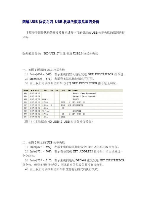
数据采集设备:“HD-USB12”全速/低速USB2.0协议分析仪一、如图1所示的USB枚举失败1)Index[666 - 668]:表示主机向默认地址发送GET_DESCRIPTOR指令包。
2)Index[670 - 671]:表示设备默认地址端点不可用。
3)由上我们可以推断出固件代码对GET_DESCRIPTOR指令包无响应。
(图1)(本数据由HD-USB12 USB协议分析仪采集)二、如图2所示的USB枚举失败1)Index[697 - 699]:表示主机向默认地址发送SET_ADDRESS指令包。
2)Index[701 - 703]:表示设备完成SET_ADDRESS指令后,给主机发送一个空应答。
3)Index[705 - 710]:表示主机向地址DEC=01重复发送SET_DESCRIPTOR 指令包,但设备无任何应答,因此该事务包设备并没有接收到。
4)由上我们可以推断出固件中设置地址的代码执行失败。
(图2)(本数据由HD-USB12 USB协议分析仪采集)三、如图3所示的USB枚举失败(图3为过滤掉IN + NAK及SOF包后的数据)1)Index[694 - 696]:表示主机向默认地址发送SET_ADDRESS指令包。
但设备对该指令答,无应答。
2)由上我们可以推断出固件代码对SET_ADDRESS指令包无响应或响应没发送空应答。
(图3)(本数据由HD-USB12 USB协议分析仪采集)四、设备发送给主机的描述信息不完整,如少发送接口或端点信息等导致枚举失败。
这要求分析所有采集到的数据才能发现问题。
由于数据量较大,就不用图片说明了。
以上是根据本人开发过程中曾经碰到的问题进行的总结分析,在实际情况中枚举失败的原因很多,不可能一一列出,但只要有一台总线协议分析设备能抓取数据进行分析是很容易找到原因的。
Windows系统中的常见USB设备问题及解决方法
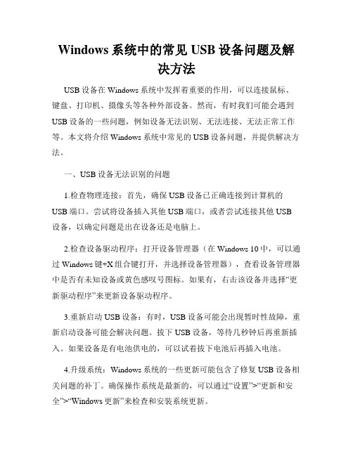
Windows系统中的常见USB设备问题及解决方法USB设备在Windows系统中发挥着重要的作用,可以连接鼠标、键盘、打印机、摄像头等各种外部设备。
然而,有时我们可能会遇到USB设备的一些问题,例如设备无法识别、无法连接、无法正常工作等。
本文将介绍Windows系统中常见的USB设备问题,并提供解决方法。
一、USB设备无法识别的问题1.检查物理连接:首先,确保USB设备已正确连接到计算机的USB端口。
尝试将设备插入其他USB端口,或者尝试连接其他USB 设备,以确定问题是出在设备还是电脑上。
2.检查设备驱动程序:打开设备管理器(在Windows 10中,可以通过Windows键+X组合键打开,并选择设备管理器),查看设备管理器中是否有未知设备或黄色感叹号图标。
如果有,右击该设备并选择“更新驱动程序”来更新设备驱动程序。
3.重新启动USB设备:有时,USB设备可能会出现暂时性故障,重新启动设备可能会解决问题。
拔下USB设备,等待几秒钟后再重新插入。
如果设备是有电池供电的,可以试着拔下电池后再插入电池。
4.升级系统:Windows系统的一些更新可能包含了修复USB设备相关问题的补丁。
确保操作系统是最新的,可以通过“设置”>“更新和安全”>“Windows更新”来检查和安装系统更新。
二、USB设备无法连接的问题1.检查USB端口:有时候,USB设备无法连接的问题可能是由USB端口损坏或松动引起的。
尝试将设备插入其他USB端口,或使用其他设备插入同一USB端口,以判断问题出在设备还是USB端口上。
2.检查USB线缆:USB线缆可能会因为长时间使用或折叠而受损,导致连接失败。
尝试使用其他USB线缆来连接USB设备,如果设备可以连接,则说明原先的USB线缆有问题。
3.检查电源供应:某些USB设备需要额外的电源供应才能正常工作。
确保USB设备的电源线已插入并连接到电源适配器或电源插座。
4.加强电源管理:在Windows系统中,USB端口默认启用电源管理以节约能源,但这可能导致某些USB设备无法连接。
DIY解决U盘和P3出现的问题
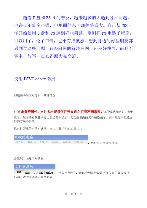
随着U盘和P3.4的普及,越来越多的人遇到各种问题。
也许盘不值多少钱,但里面的东西却关乎重大。
自己从2005年开始使用U盘和P3遇到好些问题,刚刚把P3重装了程序,可以用了,松了口气,也小有成就感。
想到身边的好些朋友都遇到过这些问题,有些问题的解决在网上还不好找到,而且不集中,故写一点心得跟大家交流。
使用USBCleaner软件问题由小到大可分以下几种情况:1.点击盘符属性,文件大小正常但打开U盘之后看不到东西。
这种情况可能是U盘中毒了,然而杀毒软件杀毒之后还是不显示,其实是里面的文件被隐藏了,而一般显示隐藏文件的方法不奏效。
这时打开我的电脑对话框,点击工具栏中的工具(T),然后点击文件夹选项会出现下面这个对话框,点击“查看”,可以看到高级设置下面罗列了好多选项,拖动右边的滚动条,直至看到,然后将那个对号取消掉,这时电脑提示“您已选择···是否显示这些文件?”,点“是”。
继续选择“显示所有文件和文件夹”前的圆圈,确定。
然后看看你的U盘里的东西是否出来了呢。
只需要把那些隐藏的文件重新拷贝一遍,改变文件的隐藏属性(在文件上右击,选择属性,取消属性一栏中的隐藏前的对号)。
为了防止做的不彻底,U盘上的病毒还在,我一般是把这些文件拷贝到电脑上,然后重新格式化U盘,再考回去。
2.U盘或P3.4里面的东西确实没办法挽救了,只需要拯救U盘,P3.4,却又无法格式化,电脑弹出“windows无法完成格式化”。
其实即使你的电脑里面安装了诸如360等软件阻止U盘自动运行,你把U盘插到电脑上的那一刻,盘上有的程序还是自动运行了。
这时,你应该在插U盘前就摁住shift键,插上U盘、P3.4后,会弹出格式化对话框,此时松开shift键再格式化就可以了(我用了几次,很奏效)。
3.由于p3.4升级失败造成机器瘫痪需要重装P3.4程序,但是电脑不读盘,根本不显示盘符,而且原来P3.4自带的驱动盘安装之后也搜索不到(一般是一直搜索,如果能搜到的话不会超过3分钟,我的用了不到1分钟检测到的)。
usb 问题解决方法
+usb_sbc2410_init();
}
3.内核配置
>让内核支持热插拔
General setup ---> Support for hot-pluggable devices
>USB驱动设置
Device Drivers --->Generic Driver Options
SCSI device support
---> SCSI generic support
Probe all LUNs on each SCSI device
以下是挂载usb设备后的显示:
[root@Emux /]# mount -t vfat -o iocharset=cp936 /dev/ub/a/part1 /mnt
[root@Emux /]# ls /mnt
4.移植小结
>如果想知道内核有没有识别出u盘的话可以执行命令:cat /proc/partitions ,看看插入USB前后分区信息有什么不同就知道了
+{
+unsigned long upllvalue = (0x78<<12)|(0x02<<4)|(0x03);
+printk("USB Control, (c) 2006 sbc2410\n");
+s3c_device_usb.dev.platform_data = &usb_sbc2410_info;
+static struct s3c2410_hcd_info usb_sbc2410_info = {
Intel USB4 评估坞站更新手册说明书

Intel USB4 Evaluation Dock Update ManualINFORMATION IN THIS DOCUMENT IS PROVIDED IN CONNECTION WITH INTEL® PRODUCTS. NO LICENSE, EXPRESS OR IMPLIED, BY ESTOPPEL OR OTHERWISE, TO ANY INTELLECTUAL PROPERTY RIGHTS IS GRANTED BY THIS DOCUMENT. EXCEPT AS PROVIDED IN INTEL'S TERMS AND CONDITIONS OF SALE FOR SUCH PRODUCTS, INTEL ASSUMES NO LIABILITY WHATSOEVER, AND INTEL DISCLAIMS ANY EXPRESS OR IMPLIED WARRANTY RELATING TO SALE AND/OR USE OF INTEL PRODUCTS, INCLUDING LIABILITY OR WARRANTIES RELATING TO FITNESS FOR A PARTICULAR PURPOSE, MERCHANTABILITY, OR INFRINGEMENT OF ANY PATENT, COPYRIGHT, OR OTHER INTELLECTUAL PROPERTY RIGHT.A "Mission Critical Application" is any application in which failure of the Intel Product could result, directly or indirectly, in personal injury or death. SHOULD YOU PURCHASE OR USE INTEL'S PRODUCTS FOR ANY SUCH MISSION CRITICAL APPLICATION, YOU SHALL INDEMNIFY AND HOLD INTEL AND ITS SUBSIDIARIES, SUBCONTRACTORS AND AFFILIATES, AND THE DIRECTORS, OFFICERS, AND EMPLOYEES OF EACH, HARMLESS AGAINST ALL CLAIMS COSTS, DAMAGES, AND EXPENSES AND REASONABLE ATTORNEYS' FEES ARISING OUT OF, DIRECTLY OR INDIRECTLY, ANY CLAIM OF PRODUCT LIABILITY, PERSONAL INJURY, OR DEATH ARISING IN ANY WAY OUT OF SUCH MISSION CRITICAL APPLICATION, WHETHER OR NOT INTEL OR ITS SUBCONTRACTOR WAS NEGLIGENT IN THE DESIGN, MANUFACTURE, OR WARNING OF THE INTEL PRODUCT OR ANY OF ITS PARTS.Intel may make changes to specifications and product descriptions at any time, without notice. Designers must not rely on the absence or characteristics of any features or instructions marked "reserved" or "undefined". Intel reserves these for future definition and shall have no responsibility whatsoever for conflicts or incompatibilities arising from future changes to them. The information here is subject to change without notice. Do not finalize a design with this information.The products described in this document may contain design defects or errors known as errata which may cause the product to deviate from published specifications. Current characterized errata are available on request. Contact your local Intel sales office or your distributor to obtain the latest specifications and before placing your product order. Copies of documents which have an order number and are referenced in this document, or other Intel literature, may be obtained by calling 1-800-548-4725, or goto: /design/literature.htm.All information provided related to future Intel products and plans is preliminary and subject to change at any time, without notice.Intel and the Intel logo are trademarks or registered trademarks of Intel Corporation or its subsidiaries in the United States and other countries.* Other names and brands may be claimed as the property of others.Copyright © 2020, Intel Corporation. All rights reserved.Important: Intel USB4 Evaluation Dock should be Powered off (No Power Supply must be Connected to the Board) when updating FW1.Equipment:1.1Dediprog SF600 (used to update the following components on the Intel USB4 EvaluationDock):Goshen Ridge: U8 – GR NVMDelta Bridge: UB10 – DB NVMUSB2.0 Hub: UB6 – USB2 HUB NVMFigure 1: Dediprog SF600SF600 SPI NOR Flash Programmer-Reference Link:https:///product/SF600-Link for downloading software:https:///download?productCategory=SPI+Flash+Solution&productName=SF600+SPI+NOR+Flash+Programmer&fileType=10Figure 2: Test ClipISP Testclip (SO8) (Compatible with SF100)Model Name: ISP-TC-8ISP Testclip (SO8) (Compatible with SF100)Reference Link: https:///product/ISP-TC-81.2Cypress MiniProg4 Program and Debug Kit CY8CKIT – 005 (used for updating thefollowing components):Cypress DMC (J5)Cypress CCG5(J4).Figure 3: Cypress MiniProg4 Program and Debug Kit CY8CKIT – 005-Reference Link: https:///product-detail/en/CY8CKIT-005/428-4713-ND/10314122?utm_medium=email&utm_source=oce&utm_campaign=3103_OCE20 RT&utm_content=productdetail_US&utm_cid=457843&so=64303907&mkt_tok=ey JpIjoiTURjNVlXVTBOekV4TW1aaSIsInQiOiJabjNuUjdzczgxZ0NCdWJBbExnR2k 3czkxNjhhZUVRcEFRdjlGSEZzeVZNNzdHcDRBSnEyYzhwa1F4QUJWS1NUeTJ wcEtXV1Z6d2tlbnpQbHUxamJCU1hqUHNhd3I4c1ZBaEd0WWtBUklLc0VsZ3F5T nc2eVRsYkZubXJrTm14dyJ9-Link for downloading software (Name of software: Download PSoC Programmer3.x.x.exe):https:///documentation/software-and-drivers/psoc-programmer-archiveNote: You need to create an account to able to download softwareNote: You need buy 5 Female to Male External Jumper for connecting.Figure 4: Female To Male Jumper-Reference Link: https:///GenBasic-Female-Solderless-Breadboard-Prototyping/dp/B077N7J6C4/ref=sr_1_7?dchild=1&keywords=male+to+female+jumper+wires&qid=1600894633&sr=8-7ponent Side and Back Side of Intel USB4 Evaluation DockFigure 5: Intel USB4 Evaluation Dock Component SideGR JTAG PA (UFP)DBR JTAGGR NVMCCG5 SWD Headers DMC SWD HeadersTMU CLKOUTFigure 6: Intel USB4 Evaluation Dock Back SideUB6 –USB2 HUB NVM UB10 – DB NVM Pin 0Pin 0Intel USB4 Evaluation Dock BKC File exampleGoshen Ridge: GR_4C_A0_rev9_ GATKES_BOARD.binDelta Bridge: DBR_CDR_ON_BOARD_rev1_NOSEC_sign.binFresco Hub: UB6_RegisterOnly_AddHeader_Merged_INTEL_1U5D_FL5801_1Q1_V02Cypress PD: DMC: CY7C65219‐40LQXIT_dmc_gatkex_creek_sha_3_3_0_1746_1_3_19_120W.hex CCG5: CYPD5235‐96BZXI_gatkex_3_3_1_39_2_8_0_nb.hex3.GoshenRidge FW UpdateExample file: GR_4C_A0_rev9_ GATKES_BOARD.bin-Step 1: Plug Dediprog SF600 flasher to PC-Step 2: Open Dediprog Engineering Application:o Go to Config Menu at the Top→Select Batch Operations(Top Left)→Check the Batch Operation Options is the same as Yellow Hightlight (see Figure 7) -→everything else leave as defaultFigure 7: Batch Operation Options- Step 3: Open U8 – NVM and take out the chip inside (see Figure 8)Figure 8: Chip inside U8 NVM- Step 4: Connect the SPI flash component to flasher (chip inside U8).Note: Make sure pin 0 of the chip is at the white line of the clip (see Figure 9)Figure 9: Connect the SPI Flash component to flasher (U8)- Step 5: Detect → choose First Chip number in the Memory list. (See Figure 10)- Note: If you do not see Memory list after Detect Chip → Please check the Connection between Chip and Test Clip-→Make sure they are connected correctlyPin 0Figure 10: Choose the chip from memory listNote: Majority of the time, the first component in the list is the correct chip.-Step 6: File load Goshen Ridge FW from BKC file bin file (See Figure 11), Select OKFigure 11: Load Intel USB4 Evaluation Dock bin file-Step 7: Batch-Step 8: Wait for all stages are PASS(see Figure 12), and Operation CompletelyFigure 12: All stages are PASSNote:-All stages are PASS only if you choose the correct chip in step 5.-In case you choose the wrong chip in step 5, you will see the following messageFigure 13: Error message after Batch when we choose the wrong chip Troubleshoot:-At Step 5: Detect → choose Second Chip number(W25Q168) of component in the list -Repeat Step 6 to Step 8-If Error:Programming Fail Message still occur→ At Step 5: Detect → choose Third Chip number (W25Q16CL)-Repeat Step 6 to Step 8-Step 9: Put the chip back to U8 GR NVM. Make sure pin 0 is on arrow position of U8 GR NVM .-Figure 14: Arrow Position of U8 GR NVM. Pin0 of Chip will go here4. Delta Bridge FW UpdateExample File: DBR_CDR_ON_BOARD_rev1_NOSEC_sign.bin Delta Bridge FW will be updated into UB10 componentFigure 15: Pin 0 at UB10While Dediprog SF600 flasher connected to PC and Dediprog application open:- Step 1: Connect the SPI flash component to flasher (UB10). Make sure the white linein the test clip connect to pin 0 (see Figure 16)Figure 16: Connect the SPI flash component to UB10-Step 2: Detect → choose First Chip number in the Memory list. (See Figure 17) -Note: If you do not see Memory list after Detect Chip→ Please check Connectionbetween Chip and Test Clip → Make sure they are connected correctlyFigure 17: Choose the chip from memory listNote: For most of the time, the first component in the list is a correct chip.-Step 3: File load Delta Bridge FW from BKC file bin file (See Figure 18)Figure 18: Load Intel USB4 Evaluation Dock bin file-NOTE:You may need to hold test clip to make sure test clip and chip connected. -Step 4: Batch-Step 5: Wait for all stages are PASS (see Figure 19) and Operation Completed.Figure 19: All stages are PASSNote:-All stages are PASS only if you choose the correct chip in step 2.-In the case you choose the wrong chip in step 2, you will see the following messageFigure 20: Error message after Batch when we choose the wrong chip-Troubleshoot:-At Step 3: Detect → choose Second Chip number (W25Q80) of component in the list -Repeat Step 3 to Step 5-If Error:Programming Fail Message still occur→ At Step 2: Detect → choose Third Chip number(W25Q80BL)-Repeat Step 3 to Step 55. Fresco Hub FW UpdateExample File:UB6_RegisterOnly_AddHeader_Merged_INTEL_1U5D_FL5801_1Q1_V02 Fresco Hub FW Update into UB6 componentFigure 21: Pin 0 at UB6While Dediprog SF600 flasher connected to PC and Dediprog application open:- Step 1: Connect the SPI flash component to flasher (UB6). Make sure the white line in the clip connect to bit 0.- Step 2: Detect → choose First Chip number in the Memory list. (See Figure 22) - Note: If you do not see Memory list after Detect Chip → Please check Connectionbetween Chip and Test Clip →Make sure they are connected correctlyFigure 22: Choose the chip from memory listNote: For most of the time, the first component in the list is the correct chip.-Step 3: File load Fresco USB Hub FW from BKC file bin file (See Figure 23)Figure 23: Load Intel USB4 Evaluation Dock bin file-NOTE:You may need to hold test clip to make sure test clip and chip connected. -Step 4: Batch-Step 5: Wait for all stages are PASS (see Figure 24), and Operation CompletelyFigure 24: All stages are PASSNote:-All stages are PASS only if you choose the correct chip in step 2.-In the case you choose the wrong chip in step 2, you will see the following messageFigure 25: Error message after Batch when we choose the wrong chip -Troubleshoot:-At Step 3: Detect → choose Second Chip number(W25Q168) of component in the list -Repeat Step 3 to Step 5-If Error: Programming Fail Message still occur→ At Step 2: Detect → choose Third Chip number(W25Q16CL)-Repeat Step 3 to Step 56. Cypress DMC FW UpdateExample DMC: CY7C65219‐40LQXIT_dmc_gatkex_creek_sha_3_3_0_1746_1_3_19_120W.hex Example CCG5: CYPD5235‐96BZXI_gatkex_3_3_1_39_2_8_0_nb.hex- Step 1: Plug Cypress MiniProg4 Program and Debug Kit CY8CKIT to the PC - Step 2: Connect MiniProg4 to DMC SWD connector (J5).Note: Only flash to the top five header pins of DMC SWD-- - - -Figure 26: DMC Headers (pin 6 to pin 10)-- Note: Make sure jumper connected to SWDIO pin of Cypress MiniProg4 connect toPin 10 at DMC header Cypress Minipro4 PinIntel USB4 Evaluation Dock DMCHeader PinSWDIO Pin 10 SWCLK Pin 9-CLK XRES Pin 8-XRES GND Pin 7-GND VTARG Pin 6-VDD-Step 3: Open Cypress PSOC programmerFigure 27: Cypress PSOC programmerNote: Make sure you see MiniProg4 in Port Selection-Step 4: Load file – DMC FW hex file (It may be inside PD folder from BKC file)Figure 28: Load file-Step 5: ProgramFigure 29: Select program on PSOC Programmer-Step 6: Wait until everything is PASSFigure 30: Wait until everything is PASSNote: If you see FAIL message, you may get the connection wrong between Cypress MiniProg4 and DMC header→ Check connection again at Step 2If connection between Cypress MiniProg4 and DMC header are correct but still get FAIL message→Close PSOC Programmer application and detach/attach MiniProg4 to host and reopen PSOC Programmer.7.Cypress CCG5 FW UpdateCCG5ABCCG5CDFigure 31: CCG5 SWD (J4) ConnectorWhile Cypress MiniProg4 Program and Debug Kit CY8CKIT connected to the PCand Cypress PSOC programmer open:Update CCG5 AB:-Step 1: Connect Cypress MiniProg4 to first CCG5 AB (J4) connectorCypress Minipro4 Pin Intel USB4 Evaluation Dock DMCHeader PinSWDIO Pin 10SWCLK Pin 9XRES Pin 8GND Pin 7VTARG Pin 6--Step 2: Load file – CCG5 FW hex file-Step 3: Program-Step 4: Wait until everything is PASSUpdate CCG5 CD:-Step 1: Connect Cypress MiniProg4 to first CCG5 CD (J4) connectorCypress Minipro4 Pin Intel USB4 Evaluation Dock DMCHeader PinSWDIO Pin 1SWCLK Pin 2XRES Pin 3GND Pin 4VTARG Pin 5-Step 2: Load file – CCG5 FW hex file (the same file for CCG5 AB update)-Step 3: Program-Step 4: Wait until everything is PASSNote: There is only 1 CCG5 file for CCG5 AB and CCG5 CDNote: If you see FAIL message, you may get connection wrong between CypressMiniProg4 and DMC header→ Check connection again at Step 1If connection between Cypress MiniProg4 and DMC header are correct but still get FAIL message→Close PSOC Programmer application and detach/attach MiniProg4 to host and reopen PSOC Programmer.-Step 5: Power Intel USB4 Evaluation Dock。
usb识别为未知设备设备描述符请求失败的解决方法
usb识别为未知设备设备描述符请求失败的解决方法当我们将USB设备连接到计算机时,通常会自动识别并安装驱动程序。
然而,有时候我们可能会遇到USB设备被识别为未知设备,设备描述符请求失败的问题。
这个问题可能出现在Windows、Mac或Linux系统中。
在本文中,我将介绍一些可能的解决方法来解决USB设备被识别为未知设备的问题。
1.检查USB连接和设备首先,要确保USB设备的连接良好。
可以尝试重新插拔设备,或者用不同的USB端口进行尝试。
有时候,USB接口可能损坏或松动导致设备无法正常工作。
另外,如果使用的是USB扩展坞、集线器或分线器,也可以尝试直接连接到计算机来排除这些设备可能引起的问题。
2.更新驱动程序设备描述符请求失败的原因可能是由于计算机没有正确的驱动程序来识别USB设备。
因此,尝试更新设备的驱动程序是解决问题的第一步。
可以通过以下步骤来更新驱动程序。
a.打开“设备管理器”b.在设备管理器中找到未知设备,通常可以在“通用串行总线控制器”或“其他设备”下找到。
c.鼠标右键点击未知设备并选择“属性”d.在属性窗口中,点击“驱动程序”选项卡e.选择“更新驱动程序”以自动搜索可用的驱动程序,或者选择“浏览计算机以查找驱动程序”以手动选择和安装驱动f.如果驱动程序已经是最新的,那么可以尝试卸载设备并重新启动计算机,让系统重新安装驱动程序。
3.禁用电源管理功能电源管理功能可能会导致USB设备无法正常工作。
尝试禁用电源管理功能可以解决USB设备被识别为未知设备的问题。
a.打开“设备管理器”b.在设备管理器中找到未知设备c.鼠标右键点击未知设备并选择“属性”d.在属性窗口中,点击“电源管理”选项卡e.取消勾选“允许计算机关闭此设备以节省电源”选项f.点击“确定”保存更改,并重新启动计算机。
4.清除USB驱动程序缓存USB驱动程序缓存可能会导致设备描述符请求失败的问题。
清除USB驱动程序缓存可以解决这个问题。
usb枚举apdu指令重复

usb枚举apdu指令重复USB枚举APDU指令重复的情况可能是由于设备或系统出现问题导致的。
以下是一个USB 枚举流程:1. 枚举流程:- 连接了设备的HUB在HOST查询其状态改变端点时返回对应的bitmap,告知HOST 某个PORT状态发生了改变。
- 主机向HUB查询该PORT的状态,得知有设备连接,并知道了该设备的基本特性。
- 主机等待设备上电稳定,然后向HUB发送请求,复位并使能该PORT。
- HUB执行PORT复位操作,复位完成后该PORT就使能了。
现在设备进入到defalut 状态,可以从Vbus获取不超过100mA的电流。
主机可以通过0地址与其通讯。
- 主机通过0地址向该设备发送get_device_descriptor标准请求,获取设备的描述符。
- 主机再次向HUB发送请求,复位该PORT。
- 主机通过标准请求set_address给设备分配地址。
- 主机通过新地址向设备发送get_device_descriptor标准请求,获取设备的描述符。
- 主机通过新地址向设备发送其他get_configuration请求,获取设备的配置描述符。
- 根据配置信息,主机选择合适配置,通过set_configuration请求对设备而进行配置。
这时设备方可正常使用。
2. GET_DESCRIPTOR:总线复位及向默认地址0发送GET_DESCRIPTOR指令包,请求设备描述。
如图一所示:- Index(4-5):表示USB插入总线复位。
- Index(7-8):表示主机向默认地址发送GET_DESCRIPTOR指令包,详细信息也抓出来了。
- Index(15-17):表示设备向主机发送设备描述数据Index(16)。
- Index(18-19):表示主机完成GET_DESCRIPTOR指令后,给设备发送一个空应答。
3. SET_ADDRESS:再次复位总线及向设备发送SET_ADDRESS指令包,设置设备地址。
USB无法识别故障解决方法
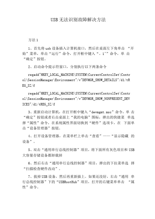
USB无法识别故障解决方法方法11、首先将usb设备插入计算机接口,然后在桌面左下角单击“开始”菜单,单击“运行”命令,打开框中键入“。
1^”命令,单击“确定”按钮。
2、启动命令提示符窗口,分别执行以下两条命令regadd"HKEY_LOCAL_MACHINE\SYSTEM\CurrentControlSet\Contr ol\SessionManager\Environment"/v"DEVMGR_SHOW_DETAILS"/d1/tR EG_SZ/fregadd"HKEY_LOCAL_MACHINE\SYSTEM\CurrentControlSet\Contr ol\SessionManager\Environment"/v"DEVMGR_SHOW_NONPRESENT_DEV ICES"/d1/tREG_SZ/f3、重新启动计算机,在打开框中键入“devmgmt.msc”命令,单击“确定”按钮或者右击桌面上“我的电脑”图标,弹出的快捷菜单选择“属性”命令,在系统属性界面切换到“硬件”选项卡,在下面单击“设备管理器”按钮。
4、打开设备管理器,在菜单栏上单击“查看”——“显示隐藏的设备”。
5、双击“通用串行总线控制器”项目,将下面所有灰色项目和USB 大容量存储设备都卸载掉6、然后右击“通用串行总线控制器”项目,弹出的下拉菜单选择“扫描检查硬件改动”。
7、拔掉USB设备,然后再重新插上。
如果还没好,右击“通用串行总线控制器”下的“USBRootHub”项目,打开的右键菜单单击“属性”命令。
7、打开的属性窗口切换到“电源管理”选项卡,去掉“允许计算机关闭此设备以节约电源”,单击“确定”按钮(依次对每个USBRootHub的属性进行修改)。
方法21、单击“开始”菜单,单击“运行”命令,在打开框中键入“regedit”命令,单击“确定”按钮。
PDIUSBD12开发的一些问题集合
同意上面的说法,
为了可靠,你可以把INF文件中和你想卸载的驱动程序相关的。INF,OEM*。INF和DERIVER下的驱动都删掉,也把注册表中的也删了。一定成功。
你可以先调试你的程序看到底调用了UNLOAD了没有?一般PNP硬件插入PC机,windows系统首先是在inf文件夹里搜索相应的.inf,所以你应当从控制面板里卸载driver,在把inf文件夹你的inf删除掉。
PDIUSBD12开发的一些问题集合.txt每个女孩都曾是无泪的天使,当遇到自己喜欢的男孩时,便会流泪一一,于是坠落凡间变为女孩,所以,男孩一定不要辜负女孩,因为女孩为你放弃整个天堂。朋友,别哭,今夜我如昙花绽放在最美的瞬间凋谢,你的泪水也无法挽回我的枯萎~~~PDIUSBD12开发的一些问题集合
3 外设再一次接收到GetDescriptor请求。主机分析描述符的信息。主机操作系统根据描述符信息寻找相应的设备驱动程序。
4 操作系统会继续发出GetConfiguration请求,读取设备的配置信息。要把外设的各个端点的配置情形回送到主机中。如果有多个配置信息,有多次请求发生。
5 在设备能通讯前,主机给外设一个SetConfiguration请求,主机根据整个系统的USB使用情况确认设备的哪一个配置有效,告诉其怎样工作,设备收到后调整有关配置,使设备能合理使用。
我是菜鸟,真心请教各位了谢谢
A:把windows\\inf目录下的oem*.inf打开,找到,你的那个,因为系统会吧它改名为oem*.inf,*是不确定的,然后把它删掉。要在没插硬件的时候。然后把windows\\system32\\drivers目录下你的的驱动程序也删掉,就行了,注册表不用管。
经过上面的调试后,USB外设可以发送和接收数据,设备如果不立即使用则会进入挂起状态,直到使用。
USB常见问题及解决方法

USB常见问题及解决方法如果是windows98系统,则必须要安装相应的硬件驱动才可以正常识别,不过正规的电子外设一般都带有驱动光盘,只要按照向导的提示完成安装即可。
如果是windowsXP系统出现这样的提示,第一有可能是产品本身的质量问题,先在其他的机器上尝试一下,如果另外几台电脑都不行,则可以肯定是硬件问题。
第二,如果其他机器上可以使用,则是系统的问题,最有可能的是将系统的智能识别usb设备的服务被人为禁用(默认是打开的),将其打开的方法是:控制面板---管理工具(经典视图下)--服务,然后查看Universal Plug and Play Device Host服务项目是否被禁用,禁用的话将其设置为启用。
基本上以上所说方法都试过后应该不会再有任何问题2.我的电脑也是联想的品牌机,出现了usb无法识别的情况。
按照上面的说的拔掉主机电源,按开机键几次来释放静电,然后开机就能识别U盘了。
3.静电引发系统“无法识别的USB设备”本人使用的联想扬天M6002计算机子近四年多来没有出现任何硬件故障,近日发现连接的移动硬盘系统显示“无法识别的USB设备”现象,通过开关移动硬盘或插拔连接的USB口总不能解决问题,但在别的电脑上使用却没有一点辨别问题,而本机系统始终出现“无法识别的USB设备”。
打开“设备管理器”的“通用串口总线控制器”发现有“unkown device”设备,怀疑驱动出现问题,卸载重装多次均不见效,故障依旧,但计算机的USB光电鼠标一直可以正常使用,不管插在那一个USB口上。
根据这种现象判定:一不可能是USB设备故障,因为移动硬盘在其它计算机上能正常使用;二USB接口与主板也不会有问题,因为USB鼠标能在任何一个USB口上正常使用。
难道是操作系统出现问题?为了彻底解开这个谜团,我进行了Ghost操作系统的安装,但完成后故障依旧。
这让我犯难了,这到底是什么原因致使的呀?后,在“设备管理器”的“通用串口总线控制器”中我逐个停用USB控制器设备,我发现一个奇怪的现象:只要停用“SiS PCI to USB Enhanced Host Controller”,卸载“unkown device”设备,进行扫描检测硬件改动能找到移动硬盘,但马上又是:“unkown device”设备。
usb识别为未知设备设备描述符请求失败的解决方法

usb识别为未知设备设备描述符请求失败的解决方法USB设备被识别为未知设备或设备描述符请求失败是一种常见的USB连接问题,它可能导致设备无法正常工作。
这种问题通常出现在Windows操作系统上,但也可能在其他操作系统上发生。
在遇到这种问题时,用户可以尝试一些解决方法来修复USB设备的识别问题。
下面我们将介绍一些常见的解决方法,希望能够帮助你解决USB设备未被识别的问题。
1.重新插拔USB设备当USB设备被识别为未知设备或设备描述符请求失败时,首先要尝试的是重新插拔USB设备。
有时由于连接问题或设备驱动程序问题,USB设备可能无法正确地被识别。
这时,将USB设备从电脑上拔下,然后再重新插上,可能会解决该问题。
在重新插拔USB设备之前,建议先关闭电脑,并点亮USB设备确保其断电状态,然后再进行插拔操作。
2.更换USB端口USB设备被识别为未知设备或设备描述符请求失败可能是由于USB 端口损坏或出现连接问题导致的。
因此,你可以尝试将USB设备插入另外一个USB端口,看看是否能够解决该问题。
如果USB设备能够在其他USB端口上正常工作,那么问题很可能是由于原来的USB端口出现了问题。
3.更新驱动程序设备描述符请求失败可能是由于设备驱动程序问题导致的。
检查你的USB设备是否配备了最新的驱动程序,如果没有,你可以尝试更新USB设备的驱动程序。
在Windows操作系统上,你可以通过设备管理器来更新设备驱动程序。
右击“此电脑”或“计算机”图标,选择“管理”,然后打开“设备管理器”,找到出现问题的USB设备,右击该设备,选择“更新驱动程序软件”,然后按照提示进行操作。
4.卸载并重新安装USB设备有时,USB设备的驱动程序可能出现问题,导致设备不能正常被识别。
你可以尝试先卸载USB设备的驱动程序,然后重新安装驱动程序来解决该问题。
在设备管理器中找到USB设备,右击该设备,选择“卸载设备”,然后重新插拔USB设备,系统会自动重新安装驱动程序。
Windows系统蓝屏错误解决方法
Windows系统蓝屏错误解决方法在使用Windows操作系统的过程中,经常会遭遇到蓝屏错误的情况。
当我们遇到这种情况时,可能会感到十分困扰和恼火。
但是,不用担心,本文将为大家介绍一些常见的Windows系统蓝屏错误,并提供相应的解决方法,帮助大家解决这一问题。
一、蓝屏错误1:DRIVER_POWER_STATE_FAILURE当您在电脑上看到蓝屏错误提示DRIVER_POWER_STATE_FAILURE时,这通常是由于设备驱动程序的问题引起的。
为了解决这个问题,您可以按照以下步骤进行操作:1. 更新驱动程序:打开设备管理器,找到出问题的设备,右键单击并选择“更新驱动程序”。
您可以选择让Windows自动更新驱动程序,也可以从厂商网站下载并手动安装最新的驱动程序。
2. 检查电源管理设置:有时,错误可能是由于电源管理设置不正确引起的。
打开“电源选项”设置,确保您的电脑在使用过程中能够正常进入和退出休眠状态。
3. 升级操作系统:如果您的电脑仍然遭遇DRIVER_POWER_STATE_FAILURE错误,尝试升级操作系统到最新版本或安装必要的更新补丁。
二、蓝屏错误2:MEMORY_MANAGEMENTMEMORY_MANAGEMENT蓝屏错误通常是由于系统内存问题引起的。
以下是一些解决方法:1. 运行内存诊断工具:Windows操作系统提供了一个内置工具,可以帮助您检查和修复内存问题。
在开始菜单中搜索“Windows内存诊断”,运行该工具进行诊断和修复。
2. 更换或重新插入内存条:有时,内存条可能会松动或损坏,导致蓝屏错误。
您可以尝试重新插入内存条或更换损坏的内存条,看看问题是否得到解决。
3. 检查内存设置:有时,内存设置不正确也会导致MEMORY_MANAGEMENT错误。
您可以通过进入BIOS设置来检查内存频率和时序是否正确,并根据需要进行调整。
三、蓝屏错误3:SYSTEM_THREAD_EXCEPTION_NOT_HANDLED当您看到SYSTEM_THREAD_EXCEPTION_NOT_HANDLED蓝屏错误提示时,这通常是由于软件或驱动程序冲突引起的。
计算机组装和维修中常见的USB设备问题及解决方法

计算机组装和维修中常见的USB设备问题及解决方法现代计算机中,USB(通用串行总线)设备是我们常见的硬件之一。
USB设备的普及和广泛应用使得我们的计算机功能更加强大和多样化。
然而,在计算机组装和维修过程中,我们经常会遇到一些与USB设备相关的问题。
本文将详细介绍这些问题以及相应的解决方法。
一、USB设备无法被识别或连接无法识别或连接USB设备是最常见的问题之一。
出现这种情况时,我们应该首先检查以下几个方面:1. 确保USB设备已正确连接:检查USB设备是否已正确插入计算机的USB口,也可以试着将USB设备插到其他可用的USB口上。
2. 检查USB线缆和接口:有时候,USB线缆或接口可能损坏或松动导致连接失败。
建议更换USB线缆或试着将USB设备插到其他电脑上测试。
3. 检查驱动程序:确保计算机已正确安装相关的驱动程序。
可以在设备管理器中检查USB设备的状态和驱动程序情况,并尝试更新驱动程序。
4. 检查USB设备是否兼容:有些USB设备可能不兼容某些计算机或操作系统。
在购买USB设备前,应该先查看其兼容性信息,并确保其与计算机系统匹配。
二、USB设备速度慢或无响应有时候,USB设备的传输速度会变慢,或者设备无法响应操作。
1. 检查USB接口和设备:首先检查USB设备是否有灰尘或污垢。
清洁USB接口和设备上的接点,确保良好的接触。
2. 适当使用USB扩展器:当USB接口不够时,我们可能会使用USB扩展器。
然而,过多的USB设备连接到扩展器可能会导致速度变慢或无响应。
在使用USB扩展器时,适量连接设备,并确保扩展器与计算机的连接稳定。
3. 关闭不必要的后台程序和服务:在计算机运行过程中,一些后台程序和服务可能占用过多的系统资源,影响USB设备的传输速度。
关闭不必要的后台程序和服务,可以提升USB设备的性能。
三、USB设备断开或频繁断开有时候,我们可能会遇到USB设备频繁断开的问题,这给我们的使用带来了很大的不便。
USB插入导致电脑蓝屏解决方法
USB插入导致电脑蓝屏解决方法1、拔掉usb诺基亚E66充电,只留小米充电,还是蓝屏。
2、换到机箱后排usb口,还是蓝屏。
3、关机状态下,连接usb,还是蓝屏。
(开始怀疑是连接线的问题)4、重启,F8,安全模式下不蓝屏。
但是没有彻底解决问题。
(证明不是连接线的问题)5、插入u盘一切正常,插入小米还是蓝屏。
(证明不是排线的问题)6、仔细研究蓝屏时的错误代码,0X00000035,no more irp stack locations,发现网上帖子挺多,但没有实用性的,都是罗列一顿其他错误代码与解决方法。
无意中,看到微软网站上的上述错误代码解决办法,但它在说明中是“当您尝试登录到域时,您可能会收到一条STOP 0x00000035 NO_MORE_IRP_STACK_LOCATIONS 错误消息”,半信半疑,决定试试。
7、通过邮箱下载了网页上一个热修复补丁,但解压缩安装,系统提示,补丁太旧没必要安装。
8、继续详细阅读微软页面说明,看到一个关于“修改DfsIrpStackSize注册表项”的办法。
操作步骤如下:单击开始、单击运行,键入regedit,然后单击确定。
找到并单击以下注册表子项:HKEY_LOCAL_MACHINE\SYSTEM\CurrentControlSet\Services\Mup\Parameters在右窗格中右键单击DfsIrpStackSize,然后单击修改。
注意如果不存在DfsIrpStackSize 注册表项,您必须创建它。
若要这样做,请按照下列步骤操作:在编辑菜单上指向新建,然后单击DWORD值。
键入DfsIrpStackSize,然后按ENTER 键。
在基数框中单击十进制、在数值数据框中键入10,然后单击确定。
退出注册表编辑器,重启电脑。
9、重启电脑之后,插入小米,等了五秒,没有蓝屏。
哈哈哈,终于成功。
10、电脑设备器中显示小米手机有黄色问号,小case,下载一个小米usb驱动,是导入更新驱动,非直接安装的。
LPC2148 USB QuickStart Board 用户指南说明书

Copyright 2012 © Embedded Artists ABLPC2148 USB QuickStart BoardUser’s GuideGet Up-and-Running Quickly andStart Developing on Day 1…Embedded Artists ABDavidshallsgatan 16SE-211 45 MalmöSweden************************Copyright 2005-2012 © Embedded Artists AB. All rights reserved.No part of this publication may be reproduced, transmitted, transcribed, stored in a retrieval system, or translated into any language or computer language, in any form or by any means, electronic, mechanical, magnetic, optical, chemical, manual or otherwise, without the prior written permission of Embedded Artists AB.DisclaimerEmbedded Artists AB makes no representation or warranties with respect to the contents hereof and specifically disclaim any implied warranties or merchantability or fitness for any particular purpose. Information in this publication is subject to change without notice and does not represent a commitment on the part of Embedded Artists AB.FeedbackWe appreciate any feedback you may have for improvements on this document. Please send your comments to ***************************.TrademarksAll brand and product names mentioned herein are trademarks, services marks, registered trademarks, or registered service marks of their respective owners and should be treated as such.Table of Contents1Document Revision History4 2Introduction5 2.1Contents5 2.2Features5 2.3ESD Precaution6 2.4CE Assessment6 2.5Other Products from Embedded Artists6 2.5.1Design and Production Services7 2.5.2OEM / Education / QuickStart Boards and Kits7 3Board Design8 3.1Mechanical Dimensions10 3.2Examples11 3.2.1JTAG11 3.2.2Reset12 3.2.3I2C13 3.2.4SPI14 3.2.5LEDs15 4Getting Started16 4.1Test program16 4.2Program Development16 5Further Information171 Document Revision History2 IntroductionThank you for buying Embedded Artists’ LPC2148 USB QuickStart Board based on NXP’s ARM7TDMI LPC2148 microcontroller.This document is a User’s Guide that describes the LPC2148 USB QuickStart Board design along with the accompanying software and program development tools. The document contains information on how to use and integrate the board in your own designs, including electrical and mechanical information.2.1 ContentsThe box received when ordering the LPC2148 USB QuickStart Board contains the following: ∙The LPC2148 USB QuickStart Board.In addition, the following is needed in order to start developing applications with the LPC2148 USB QuickStart Board:∙ A DC power supply, 5-10 volt, capable of providing at least 150 mA (more if external circuits need power from the 3.3 volt supply). The LPC2148 USB QuickStart Board does not containreverse polarity protection. Consult the schematic and the LD1117 datasheet for details about the voltage regulator.∙ A serial extension cable, DB9-male to DB9-female (DB9M-DM9F), for connecting the LPC2148 USB QuickStart Board to a PC.∙ A USB cable of type: B-to-A, both male connectors.∙An optional Prototype QuickStart Board to quickly get up-and-running with the hardware. See Embedded Artists’ homepage for more information about the Prototype QuickStart Board.∙An optional JTAG interface, for program development debugging.2.2 FeaturesEmbedded Artists’ LPC2148 USB QuickStart Board lets you get up-and-running quickly with NXÅ’s ARM7TDMI LPC2148 microcontroller. The small form factor board offers many unique features that ease your development.∙NXP ARM7TDMI LPC2148 microcontroller with 512 KByte program Flash and 32+8 KByte SRAM∙All LPC2148 I/O pins are available on connectors∙12.0000 MHz crystal for maximum execution speed and standard serial bit rates -Phase-locked loop (PLL) multiplies frequency with five; 5 x 12 MHz = 60 MHz ∙32.768kHz RTC crystal∙ESD/EMI protected RS232 channel with DSUB-9 connector-Both UART #0 and #1 connected-Signals available on expansion connector∙ 2 Kbit I2C E2PROM for storing non-volatile parameters∙Onboard low-dropout voltage and reset generation.-Generates +3.3V from a single +5V supply-+3.3V available for external circuits, up to 300 mA-Power supply: 5-10 VDC, at least 150 mA,or via USB connector∙Simple and automatic program download (ISP) via RS232 channel-Circuit that automatically controls the bootloader from RS232 channel ∙Dimensions: 59 x 39.5 mm-Small form factor for easy integration-Dual 2x16 pins I/O connectors-Four layer PCB (FR-4 material) for best noise immunity2.3 ESD PrecautionPlease note that the LPC2148 USB QuickStart Board come without anycase/box and all components are exposed for finger touches – and thereforeextra attention must be paid to ESD (electrostatic discharge) precaution.Make it a habit always to first touch the metal surface of the USBconnector for a few seconds with both hands before touching any otherparts of the board. That way, you will have the same potential as the board andtherefore minimize the risk for ESD.Note that Embedded Artists does not replace boards that have been damaged by ESD.2.4 CE AssessmentThe LPC2148 USB QuickStart Board is CE marked. See separate CE Declaration of Conformity document.The LPC2148 USB QuickStart Board is a class B product.EMC emission test has been performed on the LPC2148 USB QuickStart Board. The USB interface has been in use and also powered the device during the test. General expansion connectors where internal signals are made available have been left unconnected. Connecting other devices to the product via the general expansion connectors may alter EMC emission. It is the user’s responsibility to make sure EMC emission limits are not exceeded when connecting other devices to the general expansion connectors of the LPC2148 USB QuickStart Board.Due to the nature of the LPC2148 USB QuickStart Board– an evaluation board not for integration into an end-product – fast transient immunity tests and conducted radio-frequency immunity tests have not been executed. Externally connected cables are assumed to be less than 3 meters. The general expansion connectors where internal signals are made available do not have any other ESD protection than from the chip themselves. Observe ESD precaution.Note that the LPC2148 USB QuickStart Board can also be considered to be a component if integrated into another product. The CE mark on the LPC2148 USB QuickStart Board cannot be extended to include the new (user created) product. It is the user’s responsibility to make sure EMC emission limits are not exceeded and CE mark the final product.2.5 Other Products from Embedded ArtistsEmbedded Artists have a broad range of LPC1000/2000/3000/4000 based boards that are very low cost and developed for prototyping / development as well as for OEM applications. Modifications for OEM applications can be done easily, even for modest production volumes. Contact Embedded Artists for further information about design and production services.2.5.1 Design and Production ServicesEmbedded Artists provide design services for custom designs, either completely new or modification to existing boards. Specific peripherals and I/O can be added easily to different designs, for example, communication interfaces, specific analog or digital I/O, and power supplies. Embedded Artists has a broad, and long, experience in designing industrial electro nics in general and with NXP’sLPC1000/2000/3000/4000 microcontroller families in specific. Our competence also includes wireless and wired communication for embedded systems. For example IEEE802.11b/g (WLAN), Bluetooth™, ZigBee™, ISM RF, Ethernet, CAN, RS485, and Fieldbuses.2.5.2 OEM / Education / QuickStart Boards and KitsVisit Embedded Artists’ home page, , for information about other OEM / Education / QuickStart boards / kits or contact your local distributor.3 Board DesignThis chapter contains detailed information about the electrical and mechanical design of the LPC2148USB QuickStart Board. The schematic can be downloaded in pdf format from the support page, and isrecommended to have printed out while reading this chapter. A number of example circuits are alsopresented that will lower the threshold of start developing applications with the board.Besides the LPC2148 microcontroller from NXP, the board contains an USB interface, a 3.3V low-dropout voltage regulator, a 2 Kbit I2C E2PROM with reset generation, and an ESD/EMI protected RS232 serial channel. Both UART channels on the processor can use the RS232 interface. OnlyUART #0 is however connected to the DSUB-9 connector. A red LED is connected to the reset signaland lights when reset is active, i.e., the signal is low. Power can either be supplied via the expansionconnector or via the USB connector. Powering via the USB connector should only be used if theexternal power need is limited to 100-150 mA. If the board is powered from the USB interface jumper J6 must be inserted (see schematic above). Also note that it is not allowed to both power the boardfrom the USB interface and from an external source (+5V DC). The USB interface (typically on the PC-side) can get damaged in that case. The USB interface supports the Soft Connect functionality andvoltage sense (see LPC2148 User’s Manual for more information about these functions).The microcontroller crystal frequency is 12.0000 MHz. This frequency has been selected in order to allow maximum execution speed (5 x 12 MHz = 60 MHz, which is the maximum frequency). The on-chip UART peripheral includes a fractional baud rate generator that allow standard baud rates to begenerated form the 60 MHz base clock. The USB clock is also generated from the 60 MHz clockwithout any problems.The crystal frequency can be changed to any desired value for OEM orders, provided that theconditions in the LPC2148 datasheet are met. Current requirements are (but consult the most current datasheet for latest details):∙1-30 MHz if the on-chip phase-locked loop (PLL) is not used, or∙10-25 MHz if the PLL is to be used.The design has direct and automatic support for program Array downloading (via ISP) over the RS232 serial channel. TheRS232 signal DTR controls the reset signal to the LPC2148microcontroller. The RS232 signal RTS is connected to pinP0.14 in the LPC2148 microcontroller. This pin is sampled afterFigure Figure 1 - LPC2148 QuickStart Board ISP JumpersThe board interface connectors are placed in two 2x16 pin rows along the board edges. They are 1200 mil (30.48 mm) apart. Figure 2 below illustrates the two row connectors and their signals.Note that P0.26 and P0.27 are the USB signals and should normally be left unconnected, unless and external USB connector is implemented. Sometimes P0.23 is also used by the application and should also in this case be left unconnected.Figure 2 - LPC2148 QuickStart Board Interface Connectors3.1 Mechanical DimensionsFigure 3 below contains a drawing of the board that includes mechanical measures.Figure 3 - LPC2148 QuickStart Board Mechanical Dimensions3.2 ExamplesThis section contains a few sample / illustrative circuit examples that will help you to quickly get up-and-running with the board interface design. Detailed information about the on-chip peripheral units can be found in the LPC2148 User’s Manual.3.2.1 JTAGThe LPC2148 microcontroller contains a JTAG interface that can be used for debug purposes during program development. The circuit in Figure 4 below works for many JTAG interfaces on the market, including CrossConnect from Rowley Associates, J-link from Segger, Ulink from Keil, and Wiggler from MacRaigor.The signal RTCK on the LPC2148 microcontroller is sampled during reset. Jumper J5 drives the signal low. If the signal is found low, the JTAG interface is enabled. Pin P1.26-P1.31 then changes from being general I/O pins to dedicated JTAG pins.Note that many Wiggler JTAG interfaces do not work with a processor crystal frequency above about 10 MHz. If this is the case, the crystal frequency can be changed by desoldering the 12.0000 MHz crystal and replace it with another suitable one.LPC2148 QuickStart BoardFigure 4 – Example JTAG Interface3.2.2 ResetThe on-board I2C E2PROM (CAT1025) also contains a reset generator. The reset signal will be held active (i.e., low) until the supply voltages, +3.3V, is within margins. The reset duration is typically 200 mS (consult the CAT1025 datasheet for exact details). The output reset signal is an open-collector / open-drain output. An external reset source can also control the reset generator. Figure 5 below illustrate how an external push-button can generate a reset. Note that an external driver should be an open-collector / open-drain driver.LPC2148 QuickStart BoardFigure 5 – Example External Reset Push-button3.2.3 I2CThe LPC2148 microcontroller has an on-chip I2C communication channel (actually two, but one is used and the other is optional). The LPC2148 USB QuickStart Board has connected a 2 Kbit E2PROM to this bus. More peripheral units are easily connected to the two-wire I2C bus. Figure 6 below illustrates how a pin expander circuit (PCF8574) can be connected to the I2C bus.LPC2148 QuickStart BoardFigure 6 – Example I2C InterfaceNote that the pull-up resistors (which are always needed on I2C busses) are included on the LPC2148 USB QuickStart Board., and are hence not needed on the external circuit. The pull-up resistors are 3000 ohm each (see Fel! Hittar inte referenskälla. for complete board schematics).If using the second I2C channel do not forget to connect pull-up resistors to these signals also. Note that this must be done even if the I2C functionality is not used/enabled. Pins P0.11 and P0.14 are open-drain I/Os and must have pull-up resistors when configured as outputs. This is unfortunately easy to forget.3.2.4 SPIThe LPC2148 microcontroller also has two on-chip SPI serial communication channels. Figure 7 below illustrates how serial E2PROM chip, a shift register and a SD/MMC memory card are connected to the LPC2148 USB QuickStart Board. In the schematic below, signal SSEL (i.e, P0.7) has been pulled high. This is normally required when the SPI controller operates as a ‘master’, and ‘master’ operation is typically the normal operating mode. Note however that for the LPC214x series, SSEL is no longer required to be pulled high when operating as a SPI master. It can be used as a general purpose I/O. A good use for this pin is to use it as chip select for (one of) the SPI slave(s) to communicate with.In Figure 7 below, signal P0.30 is used as an example to control the chip select to the serial E2PROM chip, but for the LPC214x series, it could just as well have been the P0.7 (SSEL) pin (or any other pin). Note that one chip select signal is requires for each external chip that is connected to the SPI bus.LPC2148 QuickStart BoardFigure 7 – Example SPI Interface3.2.5 LEDsThe port pins of the LPC2148 microcontrollers have a 4 mA driving capacity, just enough to directly drive LEDs. Figure 8 below illustrates how current is sourced from / sink to the microcontroller to drive the LEDs. The resistors limit the current to about 4 mA. The preloaded test program (described in Section 4.1 ) outputs a running-zero on all the port pins (P0.4 – P0.31, P1.16 – P1.31, except the USB pins). A circuit like the one in Figure 8 below can be used to verify correct operation (use “active low” circuit).LPC2148 QuickStart BoardFigure 8 – Example LED Driving4 Getting Started4.1 Test programThe LPC2148 USB QuickStart Board comes preloaded with a test program. This program can be used to verify that the board operates correctly. A circuit, like the one found in Figure 8 above, can be used to attach LEDs to port pins P0.4 – P0.31, P1.16 – P1.31 (except the USB pins). Pins P0.0 – P0.1 are tested via the serial channel and pins P0.2 – P0.3 are tested via the I2C bus. Connect also a USB cable between the LPC2148 USB QuickStart Board and a PC. The PC will react to the connection and signal that it has found new hardware.The test program outputs a running-zero to the port pins, meaning that one LED at a time will light (in a running-one pattern). Also, a terminal program should be attached to the RS232 DSUB-9 connector. The test program will output test information regarding the I2C and E2PROM test. Also, theUART/RS232 channel can be tested by typing characters in the terminal program.The settings for the terminal program are: 38.4 kbps, 8 data bits, no parity bits, and one stop bit (i.e., 8N1).The output from the test program will look something like in Figure 9 below. Note that the picture below is just an example and not the actual output text.Figure 9 – Example Test Program Output4.2 Program DevelopmentConsult the QuickStart Program Development User’s Manual for more information about the QuickStart Build Environment from Embedded Artists, and program development for the ARM7 in general.5 Further InformationThe LPC2148 microcontroller is a complex circuit and there exist a number of other documents with a lot more information. The following documents are recommended as a complement to this document.[1]NXP LPC2148 Datasheet/products/lpc2000/datasheet/lpc2141.lpc2142.lpc2144.lpc2146.lpc2148.pdf[2]NXP LPC2148 User’s Manual/support/documents/microcontrollers/pdf/user.manual.lpc2141.lpc2142.lpc2144.lpc2146.lpc2148.pdf[3]NXP LPC2148 Errata Sheet/support/documents/microcontrollers/pdf/errata.lpc2148.pdf[4]ARM7TDMI Technical Reference Manual. Document identity: DDI0029G/pdfs/DDI0029G_7TDMI_R3_trm.pdf[5]ARM Architecture Reference Manual. Document identity: DDI0100EBook, Second Edition, edited by David Seal, Addison-Wesley: ISBN 0-201-73719-1Also available in PDF form on the ARM Technical Publications CD[6]ARM System Developer’s Guide – Designing and Optimizing System Software, by A.N. Sloss,D Symes, C. Wright. Elsevier: ISBN 1-55860-874-5[7]Embedded System Design on a Shoestring, by Lewin Edwards.Newnes: ISBN 0750676094.[8]GNU Manuals/manual/[9]GNU ARM tool chain for Cygwin[10]An Introduction to the GNU Compiler and Linker, by Bill Gatliff[11]LPC2000 Yahoo Group. A discussion forum dedicated entirely to the NXP’s LPC2xxx series ofmicrocontrollers./group/lpc2000/[12]The Insider’s Guide to the NXP’s ARM7-Based Microcontrollers, by Trevor Martin./arm/lpc2000book/index.htmlAlso note that there can be newer versions of the documents than the ones linked to here. Always check for the latest information / version.。
电脑开机故障汇总
电脑开机故障汇总故障提示:Cache Memory Bad,Do Not enable Cache解决方法:主板高速缓存损坏导致,找售后解决故障提示:Keyboard Not Found解决方法:可能是键盘没有插牢所致,或者主板上的USB、PS2接口损坏导致,可以将键盘插牢或更换接口故障提示:Bad of Missing Command解决方法:损坏或者丢失,使用U盘到正常电脑拷贝一个然后复制到本机引导分区故障提示:开机主机不停地响,系统反复重启解决方法:一般是显卡或内存没有插牢所致,关闭电源后,打开机箱将其插牢故障提示:Disk I/O Error,Replace Disk and Enter解决方法:系统的启动文件丢失,根据提示的丢失文件,从正常的电脑拷贝一个,进入PE 系统,然后复制该文件到引导分区故障提示:CMOS Batter State Low解决方法:CMOS电池已经没电,更换电池即可故障提示:CMOS Checksum Errordefaults loaded解决方法:也有可能是电池没有电所致,但是更换后还出现这个问题,有可能是CMOS数据错误或主板电容问题,找售后故障提示:CMOS Time&Date Not Set解决方法:开机时按住DEL进入BIOS然后设置时间和日期故障提示:Boot.ini非法解决方法:Boot.ini文件中的代码被更改,可以将下面的代码保存到c:\boot.ini中[boot loader]timeout=10default=multi(0)disk(0)rdisk(0)partition(1)\WINDOWS[operating systems]multi(0)disk(0)rdisk(0)partition(1)\WINDOWS="Microsoft Windows XP Professional" /NOEXECUTE=OPTIN /FASTDETECT故障提示:找不到hal.dll解决方法:如果重新编辑过boot.ini仍然无效的话,可以从正常的电脑拷贝该文件,如果内存条损坏,也会出现该问题故障提示:Check Your System On C ,The Type of the File System is Fat32解决方法:有的时候是非正常的关机或重启导致的,一般下次正常操作就不会出现该问题。
U盘量产导致USB鼠标键盘失灵怎么办?
U盘量产导致USB鼠标键盘失灵怎么办?导读:作为电脑资讯网站的小编,同行们的经验分析也不乏有精彩绝伦的篇章。
今日发现一小编在帮同事量产U盘后,自己台式机的USB鼠标和键盘都不能用了。
于是,他花了好长时间终于解决了这个问题。
我们一起来看看吧。
首先看看电脑出现的症状:1.进入windows xp滚动条之前,鼠标和键盘都正常,进入系统后,全部失灵2.进入PE维护系统,鼠标和键盘都正常,所以可以肯定:A.主机USB接口都是正常的B鼠标和键盘都是正常的那么出现的问题肯定是USB鼠标和键盘的驱动有关。
现在有头绪了,是一个好的开始。
比较幸运的是我的PE系统也上网,于是在度娘上查询了有关这个故障问题,搜寻的结果:原因:使用量产工具对U盘进行量产时,量产工具会加载自己的USB驱动,重启电脑,导致驱动冲突,USB鼠标和键盘都失灵了,所以重启前,请先卸载量产工具的携带的驱动。
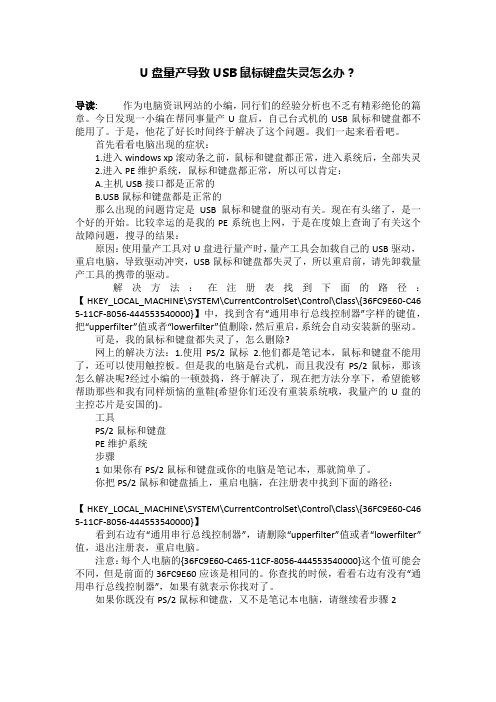
解决方法:在注册表找到下面的路径:【HKEY_LOCAL_MACHINE\SYSTEM\CurrentControlSet\Control\Class\{36FC9E60-C46 5-11CF-8056-444553540000}】中,找到含有“通用串行总线控制器”字样的键值,把“upperfilter”值或者“lowerfilter”值删除,然后重启,系统会自动安装新的驱动。
可是,我的鼠标和键盘都失灵了,怎么删除?网上的解决方法:1.使用PS/2鼠标 2.他们都是笔记本,鼠标和键盘不能用了,还可以使用触控板。
但是我的电脑是台式机,而且我没有PS/2鼠标,那该怎么解决呢?经过小编的一顿鼓捣,终于解决了,现在把方法分享下,希望能够帮助那些和我有同样烦恼的童鞋(希望你们还没有重装系统哦,我量产的U盘的主控芯片是安国的)。
工具PS/2鼠标和键盘PE维护系统步骤1如果你有PS/2鼠标和键盘或你的电脑是笔记本,那就简单了。
你把PS/2鼠标和键盘插上,重启电脑,在注册表中找到下面的路径:【HKEY_LOCAL_MACHINE\SYSTEM\CurrentControlSet\Control\Class\{36FC9E60-C46 5-11CF-8056-444553540000}】看到右边有“通用串行总线控制器”,请删除“upperfilter”值或者“lowerfilter”值,退出注册表,重启电脑。
终端-因USB口连接异常导致三星UE连接异常释放
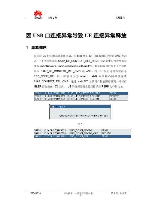
因USB口连接异常导致UE连接异常释放1 现象描述在进行UE性能测试时出现掉话,在eNB侧的S1口跟踪消息中看到eNB发起UE上下文释放请求S1AP_UE_CONTEXT_REL_REQ,该消息中可以看到原因值为radioNetwork:radio-connection-with-ue-lost。
核心网收到后发上下文释放命令S1AP_UE_CONTEXT_REL_CMD给eNB,待UE发出连接释放命令RRC_CONN_REL后(释放原因为other),eNB回给核心网释放完成S1AP_CONTEXT_REL_CMP。
通过webLMT上的用户性能跟踪发现,掉话前IBLER都收敛在10%以内,UE的管理界面上看到掉话前RSRP为-101左右。
图1图2eNB侧S1口的跟踪信息如图1所示,Uu口跟踪信息如图2所示。
2 告警信息无3 原因分析对于LTE系统中出现的掉话,常见的原因有以下几种:1、邻区漏配或者错误配置。
2、网络弱覆盖(超出了链路预算获得的最大路损得到的下行及上行的覆盖)。
3、切换导致的掉话。
切换过晚和乒乓切换等都可能会导致掉话。
4、上下行存在的干扰可能会引起掉话。
5、流程交互失败可能造成掉话,例如MIMO模式切换等。
6、其它异常原因,例如传输问题、eNB以及UE终端故障等。
接下来我们需要根据测试记录来进一步分析处理。
4 处理过程首先分析是否为邻区漏配或者错误配置引起的掉话。
如果掉话后UE马上重新接入,且UE重新接入的PCI与UE掉话时的PCI不一致,则可以怀疑是邻区错/漏配问题;站间切换时如果产生掉话,在eNB侧,观察eNB在收到UE上报的测量报告后如果没有处理,且同时X2口没有切换信令交互,也可以怀疑是邻区漏配的问题。
本次测试没有发现上述现象,而且,在webLMT上用命令LST EUTRANINTRAFREQNCELL查看同频邻区关系表没有出现漏配或者错配的情况,排除邻区漏配和错配的原因。
龙芯开发板软件应用常见问题
龙芯开发板软件应用常见问题龙芯开发板软件应用常见问题本文旨在记录龙芯开发板,上手调试以及软件编译过程中遇到的,属于非常规开发的问题(或特定知识点)及解决方法。
这些问题在龙芯官网和开发文档上没有提及或没有彻底解决,故此记录以便后续查阅。
目录1.开发板调试FAQ (3)1.1we can't locate root directory in super block! (3)1.2Can't assign requested address (3)1.3Unable to mount root fs on unknown-block (4)1.4The MEMSIZE is not supported (4)1.5如何判断PMON、kernel、FS是否成功加载 (5)1.6内核加载后控制台串口没有输出 (5)1.7上电后显示器花屏 (6)2.软件编译FAQ (7)2.1bin/sh: mipsel-linux-gcc: 未找到命令 (7)2.2bin/sh: pmoncfg: 未找到命令 (7)2.3'make menuconfig' requires the ncurses libraries. (8)1.开发板调试FAQ1.1we can't locate root directory in super block!用U盘加载方式引导开发板内核启动时可能会出现这个问题,原因是龙芯的PMON使用该加载方式时,会对存储器进行检查,要求存储器必须保留一段未分配的存储空间。
在制作内核U盘时,需要格式化U盘为ext2格式,此时可留出约5M的存储空间不要分配,如下图红色区域。
再在其它分区放入文件系统和内核即可。
1.2Can't assign requested address用网口tftp方式加载内核时可能会出现此问题,原因是PMON环境下开发板的网络端口没有配置成功。
- 1、下载文档前请自行甄别文档内容的完整性,平台不提供额外的编辑、内容补充、找答案等附加服务。
- 2、"仅部分预览"的文档,不可在线预览部分如存在完整性等问题,可反馈申请退款(可完整预览的文档不适用该条件!)。
- 3、如文档侵犯您的权益,请联系客服反馈,我们会尽快为您处理(人工客服工作时间:9:00-18:30)。
USB SMART BOARD 网上FAQ精华1
1USB SMART BOARD编译环境
PC机方面
D12TEST
1)操作系统Windows 98
2)要求安装VC++ 6.0WINNT DDK
EASY D12(EASYD12.DLL周立功公司技术支持文档)
1)VC 6.0,VB或C++ BUILDER 5.0
单片机方面
注对于51单片机的应用设计不高于24MHz的可以使用无源晶振30MHz以上建议使用有源晶
振对于USB Smart Board建议使用24MHz晶振
PHILIPS的源码(带smart_ic.asm的程序)
1) Keil C V4.0选择52以上单片机
说明:PHILIPS的源码里不带D12CI.C的文件smart_ic.asm为对D12操作的指令smart_ic.asm其实就是优化了的D12CI.C
USB51S库 V0.2版本(周立功公司技术支持文档)
1)要求Keil C V6.14以上选择52以上单片机
说明: USB51S库 V0.2版本Endpoint 1设置为中断传输方式Endpoint 2设置为批量传输方式
2问A0是命令口和数据口的地址线多地址/数据总线时接高电平但购买的D12 SMART套件印制板的A0好象只通过一10K的电阻接地固件程序中命令口和数据口的地址好象分别为0FF03 和
0FF02
答D12有两种数据总线方式多路地址/数据总线和单地址数据总线
多路地址/数据总线ALE接单片机的ALE脚这样使用MOVX指令可以与D12接口对D12的操作就像对RAM操作一样这时忽略A0的输入D12在ALE的下降沿是锁存地址信息奇数地址的输出为命令偶数地址的输出为数据
单地址数据总线ALE接地这是A0为1时使用MOVX输出的是命令A0为0时使用MOVX 输出的是数据
3问D12是否可以做主机用单片机控制来读取优盘的数据有没有可能
答不能因为D12不是USB Host 器件不能用来作为主机
4问D12能否产生中断对于控制传输的状态阶段IN读0长度数据OUT发送0长度数据给设备
答D12能产生中断
5问我发现只要是能正常工作就不会出现挂起的现象一旦挂起没有SOF那就无法正常工作是不是时序电路没什么用呢
答USB SMART BOARD的挂起的恢复是用硬件电路实现的D12检测到连续3次没有帧起始SOF
就将挂起脚置高至于测试的方法可以连接正常后把电脑进入休眠方式然后唤醒USB SMART
BOARD可以唤醒就说明是电路起作用了而上文所说的一旦挂起没有SOF那就无法正常工作
是连接不上的原因SMART BOARD与主机连接不上的时候D12检测到连续3次没有帧起始SOF
就挂起了并不能把原因和结果混淆了
6问我利用easyd12.dll中的WritePort1 ( )函数写smart板的端点1没有错误提示利用ReadPort2 ( )函数读端点2程序提示“数据响应失败”能帮我分析一下原因吗
答单片机的应答超时了ReadPort2 ( )函数读端点2 D12发送的是上一次的数据发送完数据才进
行中断请求输出当只在Endpoint 2 的IN中断中输出数据到D12是不可能产生中断的
7问原盘中附带的中文D12Test编译除了几个警告没有别的问题运行出现问题对话框的标题为Unkown Board. 测试D1D2工作正常测试扫描方式打印机方式循环读写方式都提示“请求数据传送失败”
答vc的程序是没问题的是usb51s的库是用于应用的已经把philips的厂商请求去掉了可能你
手上的smart board的板上的单片机的程序是usb51s库的demo程序就不回应philips的厂商请求所以pc的philips软件就识别固件程序就屏蔽了ep2了如果你把philips的hex代码写到58中就没问题了因为我们在用usb51s库开发自己的usb通信程序时没有必要加进philips的厂商请求
使用第三次技术支持文档的VC程序和MCU程序已经解决了这个问题
8问你的SMART 板的速度为什么只有5kB/s?
答当前速率单指发送或接收一次缓冲区数值字节数的速度时间统计单位为ms但如果发送或接收的时间小于1ms则不作统计因为时间统计的单位为1ms在1ms内发送或接收完毕的话在进行速度计算时会做成除数为0产生除法错误也就是端点2收发一次缓冲区的速度当然缓冲区的可以由一个64byte以内或多个64byte以上字节组成
平均速率指端点2的数据流量和总时间从按下开始按键开始的商
最大速率在传输过程中当前速率的最大值
具体内容请参考网站上的USB BUS里的PDIUSBD12速度测试报告
9问什么叫做“厂商ID请求”有什么作用在驱动源程序的什么部分出现厂商ID请求用来用于有特
殊要求的设备
答厂商请求是通过Endpoint 0发送一些USB1.1协议以外的指令例如可以发送设备特殊的命令在USB SMART BOARD的示范程序中用来传输版本号和对Endpoint 2操作的控制了
10问我用d12和51做的usb接口是自供电为何在windrive下得不到正确的描述符有时干脆看不到设备
答请在windrive下先建立一个inf文件安装后重新启动机器再进入windrive就可以看见了
11问谁能给我一个reg51.h
答reg51.h是keil C里的51单片机的SFR的说明文档在keil C的里带有。