Gems Simics 安装报告
multisim的安装与基本使用

Multisim 仪器仪表
Multisim 在仪器仪表栏下提供了 21 个常用仪器仪表,依次为数字 万用表、函数发生器、瓦特表、双通道示波器、四通道示波器、波特 图仪、频率计、字信号发生器、逻辑分析仪、逻辑转换器、IV 分析仪、 失真度仪、频谱分析仪、网络分析仪、Agilent 信号发生器、Agilent 万用表、Agilent 示波器,tektronix 示波器,电流检测器,LABVIEW 仪器,动态测量器
Multism 10 的安装(一)
1.主程序安装 将下载的自解压文件
NI_Circuit_Design_Suite_10_0.exe
解压到一个文件夹后,会自动出现如下界 面,选择执行Install NI Circuit Design Suite 10.0进行安装(安装序列号:F44G44444).
1. Circuit 选项 Show 栏目的显示控制如下: Labels 标签 RefDes 元件序号 Values 值 Attributes 属性 Pin names 管脚名字 Pin numbers 管脚数目 2.Workspace 环境 Sheet size 栏目实现图纸大小和方 向的设置; Zoom level 栏目实现电路工 作区显示比例的控制。 3.Wring 连线 Wire width 栏目设置连接线的线宽; Autowire 栏目控制自动连线的方式。 4.Font 字体 5.PCB 电路板 PCB 选项选择与制作电路板相关的 命令 。 6.Visibility 可视选项
Transfer(文件输出)菜单
转换到 Ultiboard 转换到其他 PCB 制版 将 Multisim 数据传给 Ultiboard 从 Ultiboard 传入数据 导出列表
Tools(工具)菜单
mSeries 系列产品安装指南说明书

Package ContentsThe mSeries package includes:●Power cables (2x)●Rack mounting bracket ears with screws●Ethernet cable●mSeries appliancemSeries rear and front panelsRear PanelFront Panel Console Console portUSB USB portsEth8 LAN port (not configured)Reset Reset switch Power indicatorSystem status indicatorHDD indicatorLCD keypad arrowsInstallation●Prepare the appliance for rack installation by fastening the bracket ears to the sides of the chassis using the provided hardware. ●Mount the appliance to your rack enclosure using the provided hardware. ●Connect the ethernet cable from your Internet modem or router to the farthest left port on the lower quad port module. ●Connect the ethernet cable from your LAN switch to the second port from the left on the lower quad port module. ●Plug in both power cables to a power source and connect them to the AC power inputs located on the rear panel. ●Review the power indicator on the front of the appliance. If the indicator is lit, the appliance is powered on. ●If the appliance is not powered on, toggle the power switch located on the rear panel.Connect to the applianceYou can connect to your appliance via the online C ommand Center portal at h ttps:///cmd . Alternatively, you can connect to your appliance from the local network, or directly using a monitor, keyboard, and mouse.Via Command CenterProvisioning a new mSeries appliance via Command Center is a convenient way to deploy and configure NG Firewall. To set up and manage your new appliance from Command Center follow these steps:1.Navigate your web browser to h ttps:///cmd.2.Log in with your Untangle Command Center account, or click C reate Account to set up an account.3.In Command Center, click A dd in the Appliances screen.4.Enter the serial number located on the side panel of your appliance.5.Click A dd to confirm the new appliance.6.After the appliance successfully adds to your account, you can select it from the list of appliances.7.Click R emote Access to connect to the administration of your new appliance.8.Continue to the setup wizard.Via network connectionAlternatively, you can connect to your NG Firewall management interface from the local area network. This is useful for example if your NG Firewall appliance cannot reach the Internet and you require local administration to configure the TCP/IP settings. To access theadministration from a local network follow these steps:1.Connect your management system to the network attached to the LAN port (Internal) of the appliance.2.Check the network status of your management system and confirm that you receive an IPv4 address in the subnet of192.168.2.0/24 (e.g. 192.168.2.100).3.In a browser, navigate to 192.168.2.1.4.Accept the SSL certificate notice in your browser and continue to the setup wizard.Via direct connectionIf neither of the previous options is available, you can connect to your appliance directly by attaching a display to the VGA port and a keyboard and mouse to any of the USB ports. At the menu on the bottom of the screen, click L aunch Client to open the administration in a browser and continue to the setup wizard.Configure the setup wizardWhen you connect to the administration for the first time, the setup wizard prompts you to configure the essential parameters to get your appliance up and running.Get StartedNG Firewall packages its premium features as apps. During your first login NG Firewall prompts you to install the recommended apps. If you do not have a license, some of the recommended apps run as a 14 day trial. The trial converts to a subscription once you apply a valid license. You can learn more about NG Firewall apps at h ttps:///untangle-ng-firewall/applications/.WarrantyThis appliance is covered by a one, two or three year manufacturer warranty based on the option chosen at the time of purchase. For a description of the warranty policy visit h ttp:///refund-return-policy.Support & DocumentationFor technical support availability, contact information, and troubleshooting tips visit h ttp://. Help resources are available in the online help system at h ttp://.。
solidworks与simmechanics的插件安装说明及仿真操作
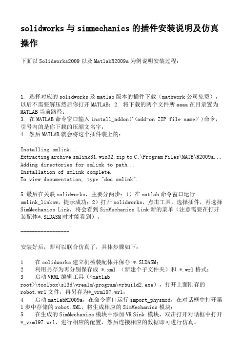
solidworks与simmechanics的插件安装说明及仿真操作下面以Solidworks2009以及MatlabR2009a为例说明安装过程:1. 选择对应的solidworks及matlab版本的插件下载(mathwork公司免费),以后不需要解压然后你打开MATLAB;2. 将下载的两个文件所aaaa在目录置为MATLAB当前路径;3. 在MATLAB命令窗口输入install_addon('<add-on ZIP file name>')命令,引号内的是你下载的压缩文名字;4. 然后MATLAB就会将这个插件装上的:Installing smlink...Extracting archive smlink31.win32.zip to C:\Program Files\MATB\R2009a... Adding directories for smlink to path...Installation of smlink complete.To view documentation, type "doc smlink".5.最后在关联solidworks,主要分两步:1)在matlab命令窗口运行smlink_linksw,提示成功;2)打开solidworks,点击工具,选择插件,再选择SimMechanics Link,将会看到SimMechanics Link新的菜单(注意需要在打开装配体*.SLDASM时才能看到)。
-----------------安装好后,即可以联合仿真了,具体步骤如下:1 在solidworks建立机械装配体并保存 *.SLDASM;2 利用另存为再分别保存成 *.xml (新建个子文件夹)和 *.wrl格式;3 启动VRML编辑工具(<matlabroot>\toolbox\sl3d\vrealm\program\vrbuild2.exe),打开上面刚存的robot.wrl文件,再另存为*_vrml97.wrl;4 启动matlabR2009a,在命令窗口运行import_physmod,在对话框中打开第1步中存储的robot.XML,将生成相应的SimMechanics模块;5 在生成的SimMechanics模块中添加VR Sink 模块,双击打开对话框中打开*_vrml97.wrl,进行相应的配置,然后连接相应的数据即可进行仿真。
IBM SUN等机器模拟软件simics的使用简介 OBP模拟
原文地址/thread-995802-1-1.html###IBM/SUN等机器模拟软件simics的使用简介& OBP模拟2010年07月19日星期一14:49simics是一款超级模拟器,可模拟多种CPU,比如可模拟Sun Blade 1500、Sun Fire 3800-680 0、Sun Enterprise 3500-6500等等,可模拟出多个CPU,硬盘,网卡....功能N强大,有兴趣的哥们可自行摸索如何配置模拟文件。
不仅如此,simics还可以同时模拟多台机器,而且这些机器通过一个虚拟的以太网链路连接在一起组成一个小网络环境。
Simics简要教程目录概览1. 安装简述2. 基本用法3. OBP模拟4. 在模拟机E6500上安装solaris10 u45. 构建虚拟网络6. 定制虚拟机型7. updating......o基本操作o保存模拟机的当前工作状态o模拟机和真机的文件对拷o调整模拟机的控制台窗口大小o向控制台发送字符o复制控制台信息o控制simics的CPU使用率o陆续上料ing......=======================================================1、安装简述1. Simics下载:google search2.Virtutech.Simics.v3.0.29注册文件:下载1:Virtutech.Simics.v3.0.29-License.zip (8.8 KB)下载2:Virtutech_Simics_3.0.29-keygen.zip (48.88 KB)安装注意点a、如果出现:「license中的用户与当前系统用户不匹配」的错误提示,请使用keygen文件生成一个License.b、badb0y:License中的用户名必须和当前系统的用户名一致,区分大小写c、月中井:「Terminal Server remote client not allowed」,请见41、42楼3.第三方组件:winpap 3.0simics安装包中自带,也可从下载。
适用于 HP-UX 的 HP Systems Insight Manager 6.0 安装与配置指南

Mitec Measuring Station RMS31 40 安装手册说明书
Power supply
11
GSM modem
12
Signal strength and antennas
12
Startup
13
General
13
Turning on the power
13
General information on settings
13
Manual settings (not normally needed)
Enclosure
21
Power supply
22
Measuring and communication
22
Measuring sensors
22
Mitec RMS40 and RMS31 measuring station
Mitec RMS40 and RMS31 measuring station
16
6 - Start measuring F5
17
Testing
18
Check sensors
18
Check communication
18
Verify system function
18
Geneasuring stations
21
Main parts
21
Current is normally regulated by the loop’s transmitter, but a break in the isolation amplifier’s secondary side can cause a voltage increase that damages the amplifier. Power over 24V is therefore not recommended unless the input is protected with a Zener diode of 10-12V.
Acme Packet 4500 Storage Expansion Module 安装指南说明书

Acme Packet 4500Storage Expansion Module Installation Guide Formerly Net-Net 4500April 2015Copyright © 2015, 2009 Oracle and/or its affiliates. All rights reserved.This software and related documentation are provided under a license agreement containing restrictions on use and disclosure and are protected by intellectual property laws. Except as expressly permitted in your license agreement or allowed by law, you may not use, copy, reproduce, translate, broadcast, modify, license, transmit, distribute, exhibit, perform, publish, or display any part, in any form, or by any means. Reverse engineering, disassembly, or decompilation of this software, unless required by law for interoperability, is prohibited.The information contained herein is subject to change without notice and is not warranted to be error-free. If you find any errors, please report them to us in writing.If this is software or related documentation that is delivered to the U.S. Government or anyone licensing it on behalf of the U.S. Government, then the following notice is applicable:U.S. GOVERNMENT END USERS: Oracle programs, including any operating system, integrated software, any programs installed on the hardware, and/or documentation, delivered to U.S. Government end users are "commercial computer software" pursuant to the applicable Federal Acquisition Regulation and agency-specific supplemental regulations. As such, use, duplication, disclosure, modification, and adaptation of the programs, including any operating system, integrated software, any programs installed on the hardware, and/or documentation, shall be subject to license terms and license restrictions applicable to the programs. No other rights are granted to the U.S. Government. This software or hardware is developed for general use in a variety of information management applications. It is not developed or intended for use in any inherently dangerous applications, including applications that may create a risk of personal injury. If you use this software or hardware in dangerous applications, then you shall be responsible to take all appropriate fail-safe, backup, redundancy, and other measures to ensure its safe use. Oracle Corporation and its affiliates disclaim any liability for any damages caused by use of this software or hardware in dangerous applications. Oracle and Java are registered trademarks of Oracle and/or its affiliates. Other names may be trademarks of their respective owners.Intel and Intel Xeon are trademarks or registered trademarks of Intel Corporation. All SPARC trademarks are used under license and are trademarks or registered trademarks of SPARC International, Inc. AMD, Opteron, the AMD logo, and the AMD Opteron logo are trademarks or registered trademarks of Advanced Micro Devices. UNIX is a registered trademark of The Open Group.This software or hardware and documentation may provide access to or information about content, products, and services from third parties. Oracle Corporation and its affiliates are not responsible for and expressly disclaim all warranties of any kind with respect to third-party content, products, and services unless otherwise set forth in an applicable agreement between you and Oracle. Oracle Corporation and its affiliates will not be responsible for any loss, costs, or damages incurred due to your access to or use of third-party content, products, or services, except as set forth in an applicable agreement between you and Oracle.About This GuideOverviewThe Acme Packet 3820 or Acme Packet 4500 Storage Expansion Module InstallationGuide describes how to install an Storage Expansion Module in your Acme Packet3820 or Acme Packet 4500 .Audience This guide is written for network administrators, and telecommunicationsequipment installers and technicians. It provides information related to hardwarecomponent installation. Only experienced and authorized personnel should performinstallation, configuration, and maintenance tasks.For information about Acme Packet 3820 or Acme Packet 4500 training, contact**********************************************************************This section contains a revision history for this document.Date DescriptionApril 2009•Initial ReleaseOctober 2013•Applied standard formatting and generalediting.April 2015 •Changed the copyright page to Oraclestandards for 2015.•Deleted a paragraph in the introduction to theStorage Expansion Module (SEM) Installationchapter suggesting that there may be revisionlevels to the motherboard that may notsupport the SEM.•Entered a note at the end of the installationchapter pointing out that after you install orreplace an SEM, you must format it.Acme Packet 4500 Storage Expansion Module Installation Guide iiiABOUT THIS GUIDEiv Acme Packet 4500 Storage Expansion Module Installation GuideAcme Packet 4500 Storage Expansion Module Installation Guide 5Storage Expansion Module Installation IntroductionThis document explains how to install the Storage Expansion Module in your Acme Packet 3820 or Acme Packet 4500.Shipped PartsThe following lists the contents of one Storage Expansion Module upgrade order.•Storage Expansion Module module•2 x mounting brackets•4 x pan head screws (M3 x 5mm)STORAGE EXPANSION MODULE INSTALLATION•4 x SEM screws (with washer) (4-40 x 1/4”)Installation Tools and Parts The following tools and parts are required to install an Storage Expansion Module in your Acme Packet 3820 or Acme Packet 4500.•#1 Phillips-head screwdriver•#2 Phillips-head screwdriver•ESD wrist strap•Cable labelsPreinstallationPerform the following logical and physical preparations before you install theStorage Expansion Module in your Acme Packet 3820 or Acme Packet 4500.Logical System Removal Be mindful of all systems and network entities that may be affected by removing a Acme Packet 3820 or Acme Packet 4500 from your network. In addition to routing calls around the Acme Packet 3820 or Acme Packet 4500, you must also prepare network monitoring and health systems to accommodate the loss of a network element.Specific procedures for removing the Acme Packet 3820 or Acme Packet 4500 from your network are beyond the scope of this document.Physical System Removal After logically removing the Acme Packet 3820 or Acme Packet 4500 from your network, the following procedures must be completed before you can install the Storage Expansion Module. These are:•Disconnection of all media network, management network, alarm and console cabling from the Acme Packet 3820 or Acme Packet 4500•Disconnection of all power and ground system cabling•Removal of the Acme Packet 3820 or Acme Packet 4500 from the equipment rackData Cabling Removal Labeling all existing data cables will ease reconnecting the Acme Packet 3820 orAcme Packet 4500 to the network.bel each cable noting which port on the Acme Packet 3820 or Acme Packet4500 it connects to.2.Attach the appropriate label to each cable.Remember to label all media network cables , maintenance cabling, and consoleand alarm cables.3.Disconnect all data cables from the Acme Packet 3820 or Acme Packet 4500.6 Acme Packet 4500 Storage Expansion Module Installation GuideSTORAGE EXPANSION MODULE INSTALLATION Acme Packet 4500 Storage Expansion Module Installation Guide 7Power and Ground Cabling Removal Take care in removing power from the Acme Packet 3820 or Acme Packet 4500.Refer to the Safety chapter in the Acme Packet 3820 or Acme Packet 4500 HardwareInstallation Guide for complete safety guidelines.The following is an overview of the power and ground cabling removal process.Please refer to the Acme Packet 3820 or Acme Packet 4500 Hardware InstallationGuide for detailed instructions.1.Shut off power to the Acme Packet 3820 or Acme Packet 4500 at the circuit breaker or power source.2.Remove the power cable(s) from the Acme Packet 3820 or Acme Packet 4500’s power supplies.3.Unscrew the two kep nuts that secure the grounding cable lug to the Acme Packet 4500 (this step is not valid for the Acme Packet 3820). 4.Remove the ground cable. Put the kep nuts in a safe place (this step is not valid for the Acme Packet 3820.Chassis Removal The Acme Packet 3820 or Acme Packet 4500 is heavy, and personal injury can resultwhile removing and installing the chassis in an equipment rack. To prevent injury or damage to the Acme Packet system, follow these guidelines:Caution To prevent personal injury, we recommend that two people lift and install the chassis into the equipment rack.•Follow your organization’s best practices for lifting and installing heavy components into an equipment rack.•Ensure that the Acme Packet 3820 or Acme Packet 4500 remains supported asyou remove it from the equipment rack.The following is an overview of the chassis removal process. Please refer to the AcmePacket 4500 Hardware Installation Guide for detailed instructions.e a workbench or other supportive surface, and place it nearby to set the Acme Packet 3820 or Acme Packet 4500 on after it is removed from the equipment rack.Support the chassis before and while removing it from the equipment rack.2.Remove the Acme Packet 3820 or Acme Packet 4500 from the rack. The number of points to unscrew depends upon whether the Acme Packetsystem is installed in a front- or center- mount configuration.3.Place the chassis on a workbench.Hardware Removal for Center-Mount Configurations The rack ears must be removed before you can open the chassis.STORAGE EXPANSION MODULE INSTALLATIONTo remove center-mount equipment rack hardware:1.Remove the left rack ear by unscrewing the three screws.2.Remove the right rack ear by unscrewing the three screws.3.Set the rack ears and screws aside.Hardware Removal for Front-Mount Configurations The chassis slides and rack ears must be removed before you can open the chassis. To remove front-mount equipment rack hardware:1.Remove the left chassis slide by unscrewing the three screws.2.Remove the left rack ear by unscrewing the three screws.3.Repeat steps 1 and 2 on the right side of the Acme Packet 3820 or Acme Packet4500.4.Set the rack ears and screws asideOpening the Chassis The chassis lid is secured to the chassis by 15 screws. Remove the screws and lift thechassis lid off the chassis.8 Acme Packet 4500 Storage Expansion Module Installation GuideSTORAGE EXPANSION MODULE INSTALLATION Acme Packet 4500 Storage Expansion Module Installation Guide 9Caution Before opening the Acme Packet 3820 or Acme Packet 4500, ground yourself using an ESD wrist strap or other comparable grounding system. Failure to do so could damage the Storage Expansion Module the Acme Packet 3820 or Acme Packet 4500.Note: Use a #2 Phillips-head screwdriver for all chassis cover and side screws.1.Unscrew the four countersunk screws on each side of the Acme Packet 4500 thathold the chassis cover to the chassis.LEFT SIDE RIGHT SIDE2.Set these screws aside.STORAGE EXPANSION MODULE INSTALLATION3.Unscrew the seven countersunk screws on the top of the Acme Packet 4500 thathold the chassis cover to the chassis. The following is an image of the top of thechassis.REAR FRONT4.Set the lid and screws aside.5.Lift the chassis lid off of the chassis and set aside.Storage Expansion Module InstallationOnce the Acme Packet 3820 or Acme Packet 4500 is open, the Storage ExpansionModule installation is straightforward. The Storage Expansion Module attacheselectrically to the Acme Packet 3820 or Acme Packet 4500 motherboard by astandard 2.5” SATA connector. In addition, it is secured to the motherboard by fourscrews.Caution Before handling the Storage Expansion Module, groundyourself using an ESD wrist strap or other comparablegrounding system. Failure to do so could damage the StorageExpansion Module or the Acme Packet 3820 or Acme Packet4500.Storage Expansion Module Preparation Before you can install the Storage Expansion Module, you must attach one mounting bracket to each side of the module. The mounting brackets are identical and can be attached to either side of the storage expansion module.10 Acme Packet 4500 Storage Expansion Module Installation Guide1.Screw one mounting bracket to one side of the storage expansion module with2 pan head screws. Ensure that the mounting bracket’s flange are on the top sideof the storage module, the side with the label.2.Repeat Step 1 for the other side of the storage expansion module.3.The storage expansion module with the mounting brackets attached resemblesthe following image:Storage Expansion Module Installation 1.Note the region on the Acme Packet 3820 or Acme Packet 4500 motherboardwhere the Storage Expansion Module attaches. In the photograph below, the Storage Expansion Module’s SATA connector is circled. The Storage ExpansionModule plugs into place here. Note the four standoffs where you will screw the storage expansion module to the chassis in step 5.2.Note the Storage Expansion Module’s SATA connector, circled in the followingphotograph.3.Place the Storage Expansion Module on the Acme Packet 3820 or Acme Packet4500 motherboard as shown in the photograph below. The Storage Expansion Module’s mounting flanges should initially be placed to the left of the fourstandoffs.4.Slide the Storage Expansion module to the right until the SATA connector seatscompletely into its mate. The holes in the mounting flanges should line up with the standoffs.5.Screw the Storage Expansion Module to the standoffs with 4 SEM screws (withwashers) as shown in the following image using a #1 Phillips screwdriver.PostinstallationAfter the Storage Expansion Module has been installed in the Acme Packet 3820 orAcme Packet 4500, you can close the chassis and reinstall it in the equipment rack. Attaching the Lid Use a #2 Phillips-head screwdriver for all chassis cover and side screws.1.Set the lid on top of the Acme Packet 3820 or Acme Packet 4500 chassis. Thestickers are positioned at the chassis rear.2.Screw the eight countersunk screws into the top of the Acme Packet 4500 to secure the chassis cover to the chassis. The following is an image of the top of the chassis without any screws.REAR FRONT3.Continue securing the chassis lid with four screws on each side.LEFT SIDE RIGHT SIDEInstalling the Chassis in the Rack Perform the reverse of the operations in the Physical System Removal section of this document:Please refer to the Acme Packet 3820 or 4500 Hardware Installation Guide for full rack installation procedures.Storage Expansion Module Validation We recommend that you validate the Storage Expansion Module (SEM) installation by running Acme Packet 3820 or Acme Packet 4500 diagnostics. All versions from nnCX_diags110.gz and later include the appropriate tests for validating the SEM. Please refer to the diagnostic’s documentation for more information.In the following procedure, after booting into diagnostics, the circled text represents a preliminary check that the system recognizes the Storage Expansion Module.Password: ******-> dc/boot/ - Volume is OK243 MB/code/ - Volume is OK245 MB/sata/ - Drive Present476940 MBStarting Diagnostic Executive...Comm Express MCH 945 Present.AHCI Support is Enabled.Acme Packet Net-Net 4500Diagnostic Executive Version 1.10Creation date: Nov 16 2009 11:08:02Board Level DiagnosticsDate & Time: TUE NOV 17 14:56:01 2009[diag_proc] ->Formatting the Storage Expansion Module After replacing the SEM, you must format it. Details on file system designs and the formatting procedure may be found in Chapter 9, File System Maintenance of the Maintenance and Troubleshooting Guide for your software release.。
Simics with Gems 安装笔记1

Simics with GEMS 安装笔记最后更新于:2010-5-7位置:自己笔记本注意事项:1)文中所有章节均标注了参考资料,其中“主要参考源”为首要参考资料,如果所列参考资料中出现冲突,则以“主要参考源”为准2)其中很多部分均为自己尝试的方法,因此在阅览本文时,最好同时阅读参考资料。
1安装Simics与GEMS本节如下内容将引导读者如何安装基本的Simics与GEMS组件,并编译通过。
1.1 安装原始Simics、GEMS主要参考资料:1)[1]中2.2/2.3 (主要参考源)2)[2]中一、二章此部分由于进行的较早,因此没有详细记录。
下面只记录几处容易出现错误的地方:1.2 安装操作系统主要参考资料:1)[2]中一、二章(主要参考源)2)[1]中2.4第一步:下载操作系统安装文件sol-9-905hw-ga-sparc-v1.isosol-9-905hw-ga-sparc-v2.iso我只能下载以上的OS版本,参考资料中的版本我均下载不到。
因此后续操作有些地方会出现细小的差别,需要特别注意。
第二步:操作系统安装1) cd $GEMS/Simics-3.0.23 /targets/serengeti2) vim abisko-sol9_cd-install1.Simics在if not defined cdrom_path 后面修改$cdrom_path= “sol-10-u2-ga-sparc-v1.iso_path”3) vim abisko-sol9_cd-install2.Simics在if not defined cdrom_path 后面修改$cd rom_path= “sol-10-u2-ga-sparc-v2.iso_path”4) cd ../../bin此步骤非常重要!以后每次从开机状态启动OS,均需要使用该路径($GEMS/Simics-3.0.23/bin)下的Simics文件5) ./Simics ../targets/serengeti/abisko-sol9-cd-install1.Simics当终端里提示出现”now exit Simics and continue with the abisko-sol9-cd-install2.Simics”时, 输入命令exit, 退出6) ./Simics ../targets/serengeti/abisko-sol9-cd-install2.Simics此处5)、6)两步骤中细节我已经记不清楚了。
simics使用手册
simics使用手册
Simics是一款模拟器,用于模拟真实硬件环境,以便进行软件和硬件的开
发和测试。
以下是Simics使用手册:
1. 安装Simics:首先需要下载和安装Simics软件。
可以从Simics官网或
其他可靠来源下载Simics安装包,按照安装向导的指引完成安装。
2. 创建虚拟机:在Simics中,可以通过创建虚拟机来模拟真实的硬件环境。
选择合适的虚拟机模板,配置虚拟机的硬件参数,如CPU、内存、磁盘等。
3. 加载操作系统:在虚拟机中加载操作系统镜像,以便进行软件测试和调试。
可以使用Simics提供的镜像管理工具加载操作系统镜像。
4. 配置网络环境:如果需要在虚拟机中进行网络通信,需要配置网络环境。
Simics支持多种网络协议,可以根据需要进行配置。
5. 运行和调试:在Simics中,可以通过仿真器进行虚拟机的运行和调试。
可以使用Simics提供的调试工具进行断点设置、寄存器查看、内存查看等
操作。
6. 导出和部署:如果需要在真实硬件上部署应用程序,可以将虚拟机的镜像导出并部署到真实硬件上。
Simics支持多种导出和部署方式,可以根据需
要进行选择。
以上是Simics使用手册的简要介绍,具体使用方法可以参考Simics官方文档或相关教程。
Magics使用说明书
1 配置环境
4.1 配置规格表
输入接口格式 INTERFACE OF INPUT
标准接口格式
STL 文件(*.stl)
支持接口格式
STEP 文件(*.stp/step) IGES 文件(*.igs/iges)
2 安装和注册 .............................................................................................................6 3 模块说明.................................................................................................................7 4 使用说明.................................................................................................................8
4.5 支撑参数详解........................................................................................................................ 29
4.5.1 公共............................................................................................................................. 29 4.5.2 基础支撑 ................................................................................................................................................ 31 4.5.3 支架支撑 ................................................................................................................................................ 32 4.5.4 点支撑 .................................................................................................................................................... 33 4.5.5 辅助支撑 ................................................................................................................................................ 34
Siemens S7-1200 PLC 安装指南说明书
T ABLE OF CONTENTS How To Use This User Guide (iv)Assumptions (iv)Contents of This Manual (iv)Installation Process Overview (v)Installation Preparation (v)Chapter 1—Introduction (1)Chapter Objective (1)Product Description (1)Features (1)Following Option (SXF) (2)Chapter 2—Getting Started (3)Chapter Objectives (3)What You Should Have (3)High and Low Power Drives (3)Chapter 3—Installation (9)Chapter Objectives (9)Installation Precautions (9)Environmental Considerations (9)Wiring Considerations (9)Preventing Electrical Noise Problems (10)Installation Overview (10)Series vs. Parallel Motor Wiring (11)Motor Configurations (12)Configuration of the Drive (19)Fan Connection (20)I/O Connections (20)OPTO1 (24)CW and CCW Limits (25)OPTO2 (25)O1—O4 Outputs (27)Encoder Connections (28)Incremental Encoder Connection (29)Absolute Encoder Connection (29)AC Power Connection (30)Transformers (30)Transformer Specifications (30)Power Ratings (31)Installation Verification (33)Input Conventions (33)Output Conventions (33)Fault Output Convention (34)Motor Test (34)Incremental Encoder Test (34)Absolute Encoder Test (35)Drive Mounting (35)Minimum Width (35)Minimum Depth (35)Attaching the Load (37)Contents iCouplings (37)Tuning (38)Resonance (38)Mid-Range Instability (38)Tuning Procedures (38)Motor Waveforms (40)Anti-Resonance (40)Chapter 4—Application Design (41)Chapter Objectives (41)Motion Profile Application Considerations (41)Preset Mode Moves (42)Incremental Mode Preset Moves (42)Absolute Mode Preset Moves (42)Continuous Mode Moves (43)Closed Loop Operation (44)Setting Encoder Resolution (45)Encoder Step Mode (45)Motion Programs and Sequences (56)Sequence Commands (56)Creating and Executing Sequences (58)Subroutines (59)Sequence Debugging Tools (63)High-Level Programming Tools (67)Complex Branching and Looping (70)Conditionals (71)Error Flag (75)Branching Using Variables and Boolean Logic (76)Motion Profiling Mode—On-the-Fly Changes (77)Interfacing to the SX (81)Programmable Inputs and Outputs (81)PLC Operation (94)Rotary vs. Linear Indexers (97)Chapter 5—SXF Follower (99)Chapter Objectives (99)What is Following? (99)Types of Following (100)Velocity Following (100)Position and Velocity Following (103)Recede and Advance While Following (115)Synchronization (132)Other Following Features (135)Following Equation and Command Summary (137)Chapter 6—Hardware Reference (143)Chapter Objectives (143)Environmental Specifications (143)Drive Electrical Specifications (143)I/O Electrical Specifications (144)Motor Electrical Specifications (147)Operational Specifications (147)Motor Current & Torque (148)Drive Dimensions (149)Motor Dimensions (150)DIP Switch Summary (152)Non-Compumotor—Drive/Motor Connection (155)Wiring Configurations.............................................................................................................................155, 156 Terminal Connections. (157)Non-Compumotor Motors—Setting Motor Current (158)Motor Performance Specifications (158)ii SX/SXF Indexer/Driver User GuideChapter 7—Maintenance & Troubleshooting (161)Chapter Objectives (161)Maintenance (161)Battery Maintenance (161)Drive Maintenance (161)Motor Maintenance (162)Common Problems and Solutions (163)Software Debugging Tips (165)Returning the System (167)Appendices (169)Command Listing (169)SX Example Programs (171)Appendix C—LVD Installation Instructions (175)Complying with the Low Voltage Directive (LVD) (175)Additional Installation Procedures for LVD Compliance (175)Table of Graphic Symbols and Warnings (177)Index (179)Contents iiiHow To Use This User GuideThis user guide is designed to help you install, develop, and maintain your system. Each chapterbegins with a list of specific objectives that should be met after you have read the chapter. Thissection is intended to help you find and use the information in this user guide. AssumptionsThis user guide assumes that you have the skills or fundamental understanding of the followinginformation.t Basic electronics concepts (voltage, switches, current, etc.)t Basic motion control concepts (torque, velocity, distance, force, etc.)Contents of This ManualThis user guide contains the following information.Chapter 1:IntroductionThis chapter provides a description of the product and a brief account of its specific features.Chapter 2:Getting StartedThis chapter contains a detailed list of items you should have received with your SX shipment. Itwill help you to become familiar with the system and ensure that each component functions properly.Chapter 3:InstallationThis chapter provides instructions for you to properly mount the system and make all electricalconnections. Upon completion of this chapter, your system should be completely installed and readyto perform basic operations. Tuning considerations and procedures are also provided.Chapter 4:Application DesignThis chapter will help you customize the system to meet your application’s needs. Importantapplication considerations are discussed. Sample applications are provided.Chapter 5:SXF FollowerThis chapter explains the SXF Following function and the SXF’s capability to support absolute andincremental encoders.Chapter 6:Hardware ReferenceThis chapter contains information on system specifications (electrical, dimensions, and perfor-mance). It may be used as a quick-reference tool for proper switch settings and connections.Chapter 7:TroubleshootingThis chapter contains information on identifying and resolving system problems.iv SX/SXF Indexer/Driver User GuideInstallation Process OverviewTo ensure trouble-free operation, pay special attention to the environment in which the SX equip-ment will operate, the layout and mounting, and the wiring and grounding practices used. Theserecommendations are intended to help you easily and safely integrate SX equipment into yourmanufacturing facility. Industrial environments often contain conditions that may adversely affectsolid-state equipment. Electrical noise or atmospheric contamination, may also affect the SXSystem.Developing Your ApplicationBefore you attempt to develop and implement your application, there are several issues that youshould consider and address.Recognize and clarify the requirements of your application. Clearly define what you expect the system todo.Assess your resources and limitations. This will help you find the most efficient and effective means ofdeveloping and implementing your application (hardware and software).Follow the guidelines and instructions outlined in this user guide. Do not skip any steps or procedures.Proper installation and implementation can only be ensured if all procedures are completed in the propersequence.Installation PreparationBefore you attempt to install this product, you should complete the following steps:Review this entire user guide. Become familiar with the user guide’s contents so that you can quickly findthe information you need.Develop a basic understanding of all system components, their functions, and interrelationships.Complete the basic system configuration and wiring instructions (in a simulated environment, not apermanent installation) provided in Chapter 2, Getting Started.Perform as many basic functions as you can with the preliminary configuration. You can only perform thistask if you have reviewed the entire user guide. You should try to simulate the task(s) that you expect toperform when you permanently install your application (however, do not attach a load at this time). Thiswill give you a realistic preview of what to expect from the complete configuration.After you have tested all of the system’s functions and used or become familiar with tll of the system’sfeatures, carefully read Chapter 3, Installation.After you have read Chapter 3 and clearly understand what must be done to properly install the system,you should begin the installation process. Do not deviate from the sequence or installation methodsprovided.Before you begin to customize your system, check all of the systems functions and features to ensure thatyou have completed the installation process correctly.The successful completion of these steps will prevent subsequent performance problems and allowyou to isolate and resolve any potential system difficulties before they affect your system’soperation.ConventionsTo help you understand and use this user guide effectively, the conventions used throughout this userguide are explained in this section.CommandsAll commands that you are instructed to enter are shown in capital letters. The symbol >, is the SXcommand prompt. The command is displayed in boldface. A delimiter (space or carriage return) isrequired after each command. A description is provided next to each command example.Command Description>MR Sets motor resolution to 25,000 steps/revThe system ignores command syntax that is not within the valid range for a specific command. A ?prompt will be returned by the drive when the last command entered was not understood, or aparameter limit was exceeded.Contents vMotorsS Series and SX Series motors are one in the same (interchangeable terms).Warnings & CautionsWarning and caution notes alert you to possible dangers that may occur if you do not follow instruc-tions correctly. Situations that may cause bodily injury are present as warnings. Situations that maycause system damage are presented as cautions. These notes will appear in bold face and the wordwarning or caution will be centered and in all capital letters. Refer to the examples shown below:WARNINGDo not touch the motor immediately after it has been in use for an extended period of time. The motormay be hot.CAUTIONSystem damage will occur if you power up the system improperly.Related Publicationst Current Parker Compumotor Motion Control Catalogt SX Indexer/Drive Software Reference Guidevi SX/SXF Indexer/Driver User Guide。
在simics中安装s

目录1介绍 (3)2准备 (3)3开始安装 (3)4配置CDE界面 (4)4.1 修改peanut-common.simics (4)4.2 修改peanut-setup.include (4)4.3 修改sunfire-6500-system.include (5)4.4 启动 (5)4.5 重新加载状态 (5)4.6 再次启动 (5)4.7 修改分辨率 (5)4.7.1存储设置状态 (6)4.7.2重启虚拟机 (6)4.8 安装中文包 (6)5常用操作 (7)5.1 图形界面下鼠标切换 (7)5.2 修改内存 (7)5.3 检查点(保存当前状态) (7)5.4 虚拟机和主机间文件复制 (7)5.4.1在虚拟机里操作 (7)5.4.2在simics中操作 (8)5.4.3虚拟光盘方式 (8)5.5 调整虚拟机的控制台窗口大小 (8)5.6 从simics向虚拟机的控制台发送字符串 (9)5.7 控制simics的CPU使用率 (9)1介绍使用Virtutech Simics 3.0.29在WIN XP(SP3)上安装solaris 10的sparc版本。
安装使用的系统光盘:sol-10-u8-ga-sparc-dvd.iso。
2准备根据simics\targets\sunfire (后续未做特殊说明,该目录简称为目录)下的peanut-sol10-cd-install1.simics中的定义,需要将光盘的名称改为:sol-10-u2-ga-sparc-v1.iso 。
然后将该光盘放在目录下。
在文件peanut-common.simics中的最前面增加一行:$memory_megs = 1024 ,即将使用的内存设置为1G。
3开始安装启动simics,新建会话,选择目录下的peanut-sol10-cd-install1.simics,开始系统的安装。
后续安装同solaris安装,不在这里详细说明。
Simics 安装
Simics 安装2011年04月27日星期三23:17Simics 是一种全系统仿真器(Simulator),最初由瑞典计算机科学研究院开发,后于1998年派生出Virtutech 公司进行商业化开发,在2010年2月被Intel 收购,之后集成到Intel 全资子公司Wind River 的产品线中。
Simics 支持IA、ARM、PowerPC、MIPS 四大主流CPU体系架构,其中尤以IA 和PowerPC 的支持最佳。
Simics 当前最新版本是4.4,支持Win32、Linux、Linux64 平台。
Simics 安装包文件名格式为:simics-pkg-<安装包编号>-4.<主版本号>.<次版本号>-<OS或类型>.<后缀名> 其中:安装包编号:xxxx 4位数字主版本号:0/2/4 (貌似只有偶数版本,学习 Linux?)次版本号:标志当前 build 版本 OS或类型:win32/linux/linux64,或者 src(源码包)后缀名:Windows 平台为 exe,linux/linux64 平台为 tar一个系统平台至少需要安装Simics-Base 和对应的板级支持包。
Simics 官方建议安装Linux64 平台版本以获得最佳的性能。
本文以Linux64 平台下的安装为例进行说明。
首先将Simics 安装包解压缩:XXX@YYY-ZZZ:~/Downloads/Simics$ tar xvf simics-pkg-1000-4.4.0-linux64.tar simics-4. 4-install/ simics-4.4-install/package-1000-4.4.0-linux64.tar.gz.tf simics-4.4-install/packa ge-1000-4.4.0-linux64.packageinfo.tf simics-4.4-install/tfdecode-linux64 simics-4.4-insta ll/installation-guide.pdf simics-4.4-install/install_simics_common.pm simics-4.4-install/in stall-simics.pl simics-4.4-install/SLA-1.3.rtf simics-4.4-install/SLA-1.3 XXX@YYY-ZZZ:~/ Downloads/Simics$ tar xvf simics-pkg-2071-4.4.0-linux64.tar simics-4.4-install/ simics-4 .4-install/package-2071-4.4.0-linux64.tar.gz.tf simics-4.4-install/package-2071-4.4.0-linu x64.packageinfo.tf simics-4.4-install/tfdecode-linux64 simics-4.4-install/installation-guid e.pdf simics-4.4-install/install_simics_common.pm simics-4.4-install/install-simics.pl sim ics-4.4-install/SLA-1.3.rtf simics-4.4-install/SLA-1.3执行安装程序:XXX@YYY-ZZZ:~/Downloads/Simics$ cd simics-4.4-install/ XXX@YYY-ZZZ:~/Downloads/ Simics/simics-4.4-install$ ./install-simics.plSimics 4.4 Installation Script =============================== You alr eady accepted a custom Simics Software License Agreement for Simics 4.4. This SLA ap plies as well to all the new packages you will install with this script. ============ =================== This script will install Simics and Simics add-on packages in a specified directory. By default, this directory is the same as for the previous install ation, or /opt/simics/simics-4.4 the first time. Encrypted packages only: If the file '$HOME/.simics-installer/4.4/tfkeys' exists, it will be searched for keys to use for package decoding. After a successful installation this file will be updated if any new keys have been used. Default alternatives are enclosed in square brackets ([ ]).安装程序会提示输入安装包密钥:-> Looking for Simics packages in current directory... Enter a decryption key for package package-1000-4.4.0-linux64.tar.gz.tf [Abort]: Enter a decryption key for package-2071-4.4.0-linux64.tar.gz.tf [Abort]:输入正确的密钥后,安装程序会提示安装Simics 到哪个目录。
Diamond Base Bench Scales 安装 维护手册说明书

Installation/Service ManualBench Scale BasesS E L E C T E D S C H E M A T I C S A N D P A R T S L I S T SM a n y p a r t s a v a i l a b l e o n l i n e . P l e a s e c a l l 800-225-2623 f o r p r o m p t s e r v i c e o n o t h e r p a r t s.I ntroduction (5)Diamond Base Bench Scales (6)Diamond Base Specs (6)Signal Cable Connections (6)Scale Setup (7)Overload Stop Adjustment (7)Cleaning Instructions (8)Torque Specification (8)Drawings and Parts List................................................10-11 Torsion Bases. (13)Torsion Base Specs (13)Leveling the Scale (13)Signal Cable Connections (13)Overload Stop Adjustments (13)Torque Specs (13)Drawings and Parts List................................................14-153600 Series QDT Bases (16)3600 Base Specs (16)Leveling the Scale (16)Signal Cable Connections (16)Replacing the Loadcell (16)Overload Stop Adjustments (17)Torque Specs (17)Drawings and Parts List................................................18-233700 Series Bases3700 Base Specs (25)Leveling the Scale (25)Signal Cable Connections (25)Overload Stop Adjustments (25)Torque Specs (25)Assy Drawings/ Parts, Outline Drawings.......................26-46Pages are numbered consecutively beginning with the cover page.3Bench Scale Bases Installation/Service ManualThis page left intentionally blank. 4Bench Scale Bases Installation/Service ManualWeigh-Tronix bench scales are divided into three types:•Diamond series bench scale analog bases•Torsion series bench scale analog bases•3600 series bench scale Quartzell bases•3700 series bench scale analog basesThis manual is divided into major sections dealing with each of these bench scale base types. There is some information which applies to all of the bases. This information is given below.Weigh-Tronix bench scale bases are available in stainless steel for use in sanitary or hostile environments and in painted carbon steel for use at less demanding sites. The Weigh-Tronix weight sensor is potted to provide corrosion resistance and to permit cleaning. A built-in bubble level and adjustable feet provide convenience in leveling the scale.Place the scale on a flat, rigid, vibration-free surface. For the diamond series or torsion series bench scales, lift the scale platform straight up, removing it from the frame. Figure 1 shows the diamond series scale. Figure 2 shows the torsion series bench scale. See Figure 3 for the 3600 series and Figure 4 for the 3700 series. Loosen each leveling-foot lock nut, as required. Adjust the leveling feet until the bubble level shows that the frame is level. All leveling feet must be in firm contact with the mounting surface. Make sure that the weight sensor signal cable is routed properly and will not interfere with platform movement. Tighten each leveling foot lock nut as required.5Bench Scale Bases Installation/Service Manual6Bench Scale Bases Installation/Service ManualTable 1Diamond Base SpecificationsPlatform Dimensions CapacityWeigh Bar Inches Centimeters lb kgOutput (mV/V)14 x 1435.56 x 35.563013.610.618 x 1845.72 x 45.725022.681.018 x 2445.72 x 60.96100/20050/1001.020 x 2050.80 x 50.8010045.351.024 x 2460.96 x 60.9620090.701.0Torque spec is 55 ft lbs for the mounting bolts Figure 1Platform Leveling AdjustmentsTable 2: Signal Cable Connections TerminalWire Desktop (NEMA IV)Color Description Connections 1GRN +Excitation B 2YEL*+Sense F 3WHT +Output C 4WHT/ORN Shield (Gnd)G 5RED -Output A 6BLU*-Sense E 7BLK -Excitation D*NotePins 1 and 2, and 6 and 7 are jumpered together when connected to a single cell analog base.Diamond Base Specs Signal CableConnections7Bench Scale Bases Installation/Service Manual Figure 2Overload stop adjustmentsThe overload stop bolts must be readjusted if either the weight sensor or any of the frame members are replaced. To adjust the overload stop bolts,refer to Figure 2 and proceed as follows:I.Lift the scale platform straight up off the frame, then replace it upside down on the five upper leveling feet. Adjust the height of the outer four to evenly support the platform. Adjust the center foot so there is a small gap (about the thickness of a sheet of paper) between it and the plat-form. Tighten all five lock nuts when adjustments are complete Scale Setup Overload stopadjustment8Bench Scale Bases Installation/Service ManualFigure 3Test weight placement for overloadstop bolt adjustment2.Refer to Figure 3 and place a test weight 102% of capacity in the center of one quadrant of the inverted platform. The weight indicator should display a reading above capacity.3.Refer to Figure 2 and loosen the stop bolt lock nut corresponding to the quadrant supporting the test weight. Adjust the overload stop bolt so that it contacts the upper frame member and the weight indicator reads less than the applied test weight. Tighten the stop bolt lock nut.4.Repeat steps 2 and 3 for each of the remaining corners of the scale.5.Remove the test weight and place the scale platform upright on the upper leveling feet. Be sure that the two static discharge wires extend straight out from the upper frame members. These static discharge wires must contact the inside corners of the platform when it is in place.6.Place 100% of capacity on the scale to verify correct operation in each corner and center of the platform.Lift the platform straight up off the frame. Thoroughly clean the frame but doNOT apply steam or high-pressure hot water directly to the Weigh Bar.Ensure no debris remains in the overload stop gaps. Thoroughly clean the platform and then place it back onto the frame.The torque specification for the weight sensor mounting bolts is 55 ft lbs.Cleaning Instructions Torque SpecificationThis page left intentionally blank.9 Bench Scale Bases Installation/Service ManualDIAMOND SERIES BASESMODEL 2020-100 (stainless) , 100 lb / 45 kg cap. , 20 “x 20” DeckMODEL 2424-200 (stainless) , 200 lb / 90 kg cap. , 24 “x 24” DeckASSEMBLY10Bench Scale Bases Installation/Service ManualDIAMOND SERIES BASESPARTS LISTNote:The above list reflects the “most commomly requested” parts for stainless version Bases only. Parts needed for Diamond Bench Scale Bases other than those listed,Call Weigh-Tronix Service 800-458-7062Note:Items 8 & 9 make up the foot with jam nut assembly PN 53296-0010This page left intentionally blank.Table 3T orsion Base SpecificationsCapacity lb kg8.75 x 8.75(22.23 x 22.23)638.75 x 8.75(22.23 x 22.23)12612 x 14(30.5 x 35.6)301512 x 14(30.5 x 35.6)603012 x 14(30.5 x 35.6)10045Torque spec is 80 in. lbs for the loadcell mounting boltsTorsion Base SpecsSignal Cable ConnectionsTable 4: Signal Cable ConnectionsWire TerminalColor Description 1Red +Excitation 2Red/White +Sense 3Green +Output 4Green/YellowShield (Gnd)5White -Output 6Black/White -Sense 7Black-ExcitationLeveling the scaleUse the leveling feet and the level bubble to level the scale platform. When the scale is level, tighten the jam nuts up against the scale base.Torque SpecsWeigh-Tronix specifies a torque of 80 (±5) in. lbs. on the loadcell mounting bolts.Platform Dimensions inches(cm)Overload Stop Adjustment The overload stop adjustment comes preset from the factory. No field adjustment is required.TORSION BASES STAINLESS6 lb, 12 lb / 9" x 9" BASE30 lb, 60 lb, 100 lb / 12" x 14" BASEASSEMBLYTORSION BASES STAINLESSPARTS LIST3600 Base Specs Signal Cable ConnectionsTable 53600 Base SpecificationsPlatform Dimensions CapacityInches Centimeters lb kg12 x 14*30.5 x 35.610512 x 14*30.5 x 35.6502512 x 14*30.5 x 35.61005012 x 14*30.5 x 35.61508018 x 1845.7 x 45.720011018 x 1845.7 x 45.7300160*Torque spec is 90 in. lbs for the Quartzell®mounting bolts. All others are 40 ft. lbs.Table 6: Signal Cable ConnectionsTerminal W-T Wire(NEMA IV)Color Description 1Red7.5 volts2Blue REC B3Yellow XMT B4—NOT USED5Black GRND6—NOT USED7Green XMT A8White REC AShell Drain wire SHIELDLeveling the scale Use the leveling feet to level the scale platform. When the scale is level,tighten the jam nuts up against the scale base.1.Remove the scale shroud and load bridge pad.2.Place your hand on the load bridge, near the two flat head screws or 9/16” bolts that hold the load bridge to the Quartzell®. Gently loosen thetwo screws or bolts with a torque wrench. DO NOT USE A “T”HANDLE ALLEN WRENCH. Doing so may cause damage to thecrystals in the Quartzell®. This damage is not covered by warranty.Remove the screws or bolts, remove the load bridge and the Quartzell®spacer.Replacing the Quartzell®Overload Stop AdjustmentsTorque SpecsWeigh-Tronix specifies a torque of 90 (±5) in. lbs. on the Quartzell mounting bolts of the 10 lb capacity base and 40 ft. lbs. on the other capacities.3.Set the scale on its side and remove the screws or bolts holding theQuartzell ® to the scale base.4.Unplug the Quartzell ® and reinstall the new Quartzell ®.5.Install the bottom bolts or screws and torque them to 90 in. lbs. (±5) forthe screws and 40 ft. lbs for the bolts. Set the scale on its feet. Reas-semble the spacer and the load bridge. Torque the screws to 90 in. lbs.(±5) and the bolts to 40 ft. lbs.6.Put the load bridge pad and shroud back on the scale.1.Place 102% of full scale capacity over each of the corners of the scale,one at a time.2.Adjust each screw until the displayed weight starts to go down. Do thisfor all corners. The center stop is normally preset at the factory. No field adjustment is required.3.Recalibrate the scale. Refer to the indicator Service Manual.3633T QDT BENCH BASE10 lb/5 kg cap. , 12" x 14" BASEASSEMBLY3633T QDT BENCH BASE10 lb/5 kg cap. , 12" x 14" BASEPARTS LIST* Center overload stops only. Stops are preset at factory and require no adjustments.3633T QDT BENCH BASE50 lb/25kg, 100 lb/50kg, 150 lb/80kg cap , 12" x 14" BASEASSEMBLY3633T QDT BENCH BASE50 lb/25kg, 100 lb/50kg, 150 lb/80kg cap , 12" x 14" BASEPARTS LIST* Item 34 is preset at factory. No field adjustment required.3635T QDT BENCH BASE 100 / 250 lb cap. , 18" x 18" BASEASSEMBLY3635T QDT BENCH BASE200 lb / 110 kg, 300 lb/160 kg cap. , 18" x 18" BASEPARTS LIST* Preset at factory, no adjustment required.This page left intentionally blank.3700 Base Specs Signal Cable ConnectionsTable 73700 Base SpecificationsPlatform Dimensions CapacityInches Centimeters lb kg10 x 10*25.4 x 25.410512 x 1430.5 x 35.6251212 x 1430.5 x 35.6502512 x 1430.5 x 35.61005018 x 18**45.7 x 45.7300160* Torque spec is 90 in. lbs for the loadcellmounting bolts.** Torque spec is 40 ft. lbs.All others are 95 in. lbs.Table 8: Signal Cable ConnectionsTerminal Wire(NEMA IV)Color Description 1Green+Excitation2—+Sense3White+Output4Drain wire Shield (Gnd)5Red-Output6—-Sense7Black-ExcitationLeveling the scale Use the leveling feet to level the scale platform. When the scale is level,tighten the jam nuts up against the scale base.Overload Stop Adjustments 1.Place 102% of full scale capacity over one of the corners of the scale.2.Adjust each screw until the displayed weight starts to go down. Do thisfor all for corners and the center stop.3.Recalibrate the scale. Refer to the indicator Service Manual.Torque Specs Weigh-Tronix specifies a torque of 90 (±5) in. lbs. on the loadcell mountingbolts.3733 BENCH BASE 10 lb/5 kg cap. , 10" x 10" BASEASSEMBLY3733 BENCH BASE10 lb/5 kg cap. , 10" x 10" BASEPARTS LIST* Preset at factory, no adjustment required.3733 BENCH BASE25 lb/12 kg, 50 lb/25 kg, 100 lb/50 kg cap.12" x 14" BASEASSEMBLY3733 BENCH BASE25 lb/12 kg, 50 lb/25 kg, 100 lb/50 kg cap.12" x 14" BASEPARTS LIST* Preset at factory, no adjustment required.3735 BENCH BASE 300 lb / 160 kg cap. , 18" x 18" BASEASSEMBLY3735 BENCH BASE300 lb / 160 kg cap. , 18" x 18" BASEPARTS LIST* Preset at factory, no adjustment required.3731LP BENCH BASE10 lb/5 kg, 25 lb/12kg, 50 lb/25 kg cap. , 10" x 10" BASEASSEMBLY3731LP BENCH BASE10 lb/5 kg, 25 lb/12kg, 50 lb/25 kg cap. , 10" x 10" BASEPARTS LIST* Preset at factory, no adjustment required.3733LP BENCH BASE 100 lb/50 kg, 250 lb/125 kg cap.14" x 14" BASEASSEMBLY3733LP BENCH BASE 100 lb/50 kg, 250 lb/125 kg cap.14" x 14" BASEPARTS LIST3735LP BENCH BASE 100 lb/50 kg, 250 lb/125 kg cap.18" x 18" BASEASSEMBLY3735LP BENCH BASE 100 lb/50 kg, 250 lb/125 kg cap.18" x 18" BASEPARTS LIST41 Bench Scale Bases Installation/Service Manual42Bench Scale Bases Installation/Service ManualBench Scale Bases Installation/Service Manual This page left intentionally blank.3731LP 10” x 10” BENCH BASE 44Bench Scale Bases Installation/Service Manual3733LP 14” x 14” BENCH BASE45Bench Scale Bases Installation/Service Manual3735LP 18” x 18” BENCH BASE 46Bench Scale Bases Installation/Service ManualThis page left intentionally blank.47 Bench Scale Bases Installation/Service ManualWeigh Bar® is a registered trademark of Weigh-Tronix Inc. September 19, 2006 BS_i.P65 PN 16783-0017S e2 Printed in USA Avery Weigh-Tronix USA1000 Armstrong Dr.Fairmont, MN 56031 USA Telephone: 507-238-4461 Facsimile: 507-238-4195e-mail:*************************** Avery Weigh-Tronix UKFoundry LaneSmethwick, West MidlandsEngland B66 2LPTel: +44 870 90 34343Fax: +44 121 224 8183Email:*******************Web site:Avery Weigh-Tronix Canada, ULC 217 Brunswick BoulevardPointe Claire, QC H9R 4R7 Canada Telephone: 514-695-0380Toll free: 800-561-9461Facsimile: 514-695-6820www.weigh-tronix.ca。
cadenceic610和mmsim61安装笔记
系统的考虑,按照道理来说应该是所有的linu x系统都能安装运行i c610的,只不过因为各个li nux组件实现不完全统一,所以在安装ic610的时候会出现各种问题,但是只要你有相关lin ux系统的知识,对于linux一些基本设计理念比较熟悉的话,应该都是可以通过调整系统来安装运行ic610的。
安装ic610的过程实际上就是一个根据ca dence给出的错误信息进行d ebug的过程,你把所有的bu g都解决了,软件也就自然能运行了。
现在已知可以运行ic610的系统r ehl,c entos,suse,ubun tu还有a rchli nux(我作证,呵呵)。
推荐使用的系统是rehl或是cent os,这两个应该是兼容性最好的,当然下面的安装过程还是以ar chlin ux为例来讲解的。
1 确认所用lin ux系统的tar版本在1.14以下,否则不能正常解压安装包。
----这一步基本废话,因为现在找的包应该是重新用高版本的tar打包过的,所以直接进行下面的就行了。
2下载安装包,包括:B ase_I C610_lnx86_1of5.tar- Base_IC610_lnx86_5o f5.ta r 五个t ar包,B ase_M MSIM61_lnx86_1o f2.ta r和Bas e_MMS IM61_lnx86_2of2.tar两个tar包,全部解压缩,将得到的IC610 cd1-cd5放在一个文件夹内,如/insta ll/ic610,将MMSIM的cd1和cd2放在另一个文件夹内,如/insta ll/mm sim。
----注意当然还要有ic610的lic ense了。
官方Colissimo模块安装指南(Magento2)说明书

Installation guide Official Colissimo Module for Magento (version 2)Table of contents1Installation (2)2Configuration (3)2.1Delivery modes (3)2.1.1La Poste Colissimo (3)2.1.2Configuring the delivery methods (3)2.2Advanced settings (3)2.2.1General settings (4)2.2.2Labels (4)2.2.3Return labels (4)2.2.4Pick-up point (5)2.2.5Mailbox collection (5)2.2.6Debugging and development (5)3Generating a delivery label (6)3.1Manual generation (6)3.2Automatic generation (7)3.3Return labels (7)4Interfaces (7)4.1Dashboard (7)4.2Shipments (8)4.2.1Scanning the delivery slip (8)4.3Delivery notes (9)4.4ColiShip (9)5Front-End (10)5.1Choosing a delivery mode (10)5.2Pickup Points (10)5.3Management in the customer account (11)6Miscellaneous (13)6.1HS code (13)6.2CRON tasks (13)6.3Non-authenticated tracking page (13)6.4Generating a Google Maps API key (13)6.5Configuring the delivery price methods (14)1InstallationThe module is available at the Magento Marketplace. We recommend installing it through the Marketplace to make updating easier. To find out which procedure to use to install a module from the Magento Marketplace, check the Magento documentation on the different steps:: https:///marketplace/user_guide/buyers/install-extension.html2ConfigurationOnce the module has been installed, two configuration entries are created in back-office. The first, "Delivery modes" (see 2.1), allows you to set the prices for the Colissimo delivery methods that will be available to the user. The second, "Advanced settings" (see 2.2), lets you configure the options for the module.2.1Delivery modesThe first part in the settings is found in: Shops -> Configuration -> Sales-> Delivery modes -> La Poste Colissimo.This part lets you configure the prices for the Colissimo delivery methods that the customer can see when ordering.2.1.1La Poste ColissimoThis button takes you to the advanced settings for the module (for more information on the advanced settings, see 2.2)2.1.2Configuring the delivery methodsThis part includes the price configuration for the different Colissimo delivery methods, which are as follows:Colissimo Domicile without signatureColissimo Domicile with signatureColissimo Collection PointColissimo ExpertThese 4 delivery methods are configured using the same structure:Activating the method: Makes the method available to the customer in the front-end at the time of the order.Name: Name of the method displayed for the customer at the time of the order.Free delivery: Makes this delivery method free, regardless of the destinations defined below.Configuration: This table allows you to set, for each geographic area, the delivery price for the customer depending on the weight. If one destination corresponds toseveral zones, the system will automatically choose the cheapest (see 6.5 forconfiguration help).2.2Advanced settingsThe second part in the settings is found in: Shops -> Configuration -> Sales->La Poste Colissimo Advanced Settings.This part allows you to set the options that will be used to run the Colissimo module, such as, for example, the APIs, delivery label management etc.2.2.1General settingsID: Colissimo identifier for using the APIs: monitoring the order status, generating Send and Return labels, retrieving pick-up points via the WebService and retrievingthe selected widget for the pick-up point.Password: Password for connecting to the API.Colissimo Box Access: Access to the La Poste company services management portal.2.2.2LabelsDelegate label generation to ColiShip?: Choose the labelling mode: via the module or via La Poste "ColiShip" service (If this option is enabled, a sample FMT file for theColiShip import is available by clicking on "Download a sample FMT file")IF ENABLED, LABELS WILL ONLY BE GENERATED VIA COLISHIP.Printing format for send labels: Choose the printing format for the send labels. This parameter is sent to the API when they are generated.Order status for generating labels: Order status that automatically generates a label once it is complete. Set to "No change" to disable automatic label generation.Order status after generating labels: Order status to be applied after generating a label.Send tracking email: Emails the link to the non-authenticated tracking page (see 6.3) for the order each time a delivery label is generated.Use Cash on Delivery?: If enabled, the generated labels will use Cash on Delivery mode.Use Colissimo insurance?: If enabled, the generated labels will use Colissimo insurance.Average preparation time: Your average preparation lead time for a delivery, in days.Recommendation level: Choose the recommendation levelGenerate the customs declaration (CN23)?: If active, each label that requires one will be accompanied by the corresponding CN23 form.Default HS code: Required for the CN23. Legal information. The value entered in this option is taken into account if it is not set at product level (see6.1)Parcel free of customs taxes and duties?: Only for shipments to the French DOM / TOM (Except St-Pierre-and-Miquelon)Type of shipment category: States the nature of the shipment (forinternational or overseas shipments subject to the CN23 declaration)2.2.3Return labelsPrinting format for return labels: Choose the printing format for return labels. This parameter is sent to the API when they are generated.Automatically create the return label when generating the return labelDisplay the name of the return service on the return label: Parameter sent to the API when the return label is generated. The name of the service (defined in thefollowing parameter) will be displayed on the return label.Name of the return serviceDisplay the order number on the return labelNumber of days for the return label purge (days):Return labels are stored in the database of the module, unlike send labels, which are stored and managed natively by Magento. This parameter prevents the module database from being overwritten by deleting return labels for which the lead time has expired.Create a return label available to the customer: Allows the customer to create his own return label through his personal account in the front-end (see 5.3).Send an email with the return label: E-mails the label as an attachment to the customer when the return label is generated.2.2.4Pick-up pointDisplay mode: Select the standard Colissimo display mode (Widget) and the customisable mode (WebService)Widget mode:Customise widget: If enabled, you can customise the font and font colour for the Colissimo widgetText colour in the address fieldText colour in the list of pick-up pointsCharacter font: Font for the pick-up point widget text.Widget URL: URL used to call the pick-up point display widget. Only changed at the request of Colissimo Support. Default value:https://ws.colissimo.fr/widget-point-retrait/resources/js/jquery.plugin.colissimo.min.jsWebService modeDisplay international pick-up points: Parameter sent to pick-up points the to retrieve international pick-up pointsGoogle Maps API Key: Google API Key to display the map displaying the pick-up points. (To generate a Google Maps API key, see 6.4)2.2.5Mailbox collectionAuthorise returns to mailboxes: If enabled, customers will be able to automatically create, via their personal account in the front-end, a return label and use it to send their parcel via their mailbox (see 5.3).2.2.6Debugging and developmentDebug mode: Logs the different actions and calls to the API by the user and module.This option lets you collect information in the event of unexpected behaviour.The log files are in the folder /var/log/colissimo.ENABLE THIS FOR SUPPORT, DISABLE WHEN NO LONGER NECESSARY.Log lifetime (days): Time before logs are deleted. Use 0 or leave blank to disable deletion.See the latest logs: Button for displaying the last 1,000 lines of the log files.3Generating a delivery labelIf the option to delegate to ColiShip is disabled (see 2.2.2), a Colissimo delivery label can be generated in several ways.TO GENERATE A DELIVERY LABEL, THE ORDER MUST HAVE BEEN INVOICED IN MAGENTO3.1Manual generationYou can manually generate a Colissimo delivery label via the traditional Magento process: Go to the order in the back-officeClick on "Ship" to go to the shipment creation pageTick the box "Create delivery label", then click "Confirm shipment…"In the panel that is displayed, select the products you want to add to the shipment then click "Save"If the option to automatically generate the return label is enabled (see 2.2.3), the return label will be automatically generated at this time.The delivery label is then located in the Magento shipments display.You can also generate a label after you create the shipment, if the box "Create delivery label" has not been ticked or if it is necessary to generate another label for example. This can be done in the Colissimo shipment listing (see 4.2).3.2Automatic generationA delivery label can be automatically generated if the option "Order status for generating labels" (see 2.2.2) is set for one or more order statuses. When the order reaches this status, the delivery label is automatically generated, on condition that it has been invoiced.As with manual generation, if the option to automatically generate the return label is enabled (see 2.2.3), the return label will be automatically generated at this time.3.3Return labelsIf the return label is not automatically generated (see 3.1 and. 3.2), you can generate it via the shipment listing (see 4.2).4InterfacesThe module adds specific interfaces to the Magento back-end for better management of Colissimo shipments.These interfaces are listed in Sales-> Colissimo.4.1DashboardThis reference interface provides an overview of the different Colissimo shipments, both current and completed.The listing shows, for each Colissimo parcel:The parcel numberThe associated order numberThe associated shipment numberThe delivery slip numberThe Colissimo status, provided by the Colissimo tracking API.If a parcel's status has not been updated for 72 hrs, a small warning symbol highlights it.If there is an anomaly with the delivery of a parcel, this is indicated with another symbol.For each parcel, the following actions can be performed:See parcelSee orderDownload label4.2ShipmentsThis interface shows a shipment listing of orders placed with a Colissimo delivery method. Ina addition to the traditional information about a shipment, there is also some specific information:Status: Status of the delivery. Information provided by the Colissimo tracking API.This is a clickable link to the non-authenticated delivery tracking page in the front-end.Label: Different label numbers generated for this shipment. The label in bold is the last label generated.The listing offers a list of possible actions for the selected shipments:Generate send or return labelsGenerate a delivery noteDownload a ZIP file containing all of the information relating to the shipments. For each shipment, there is a choice of specific actions:Print the send or return labelDownload the send or return labelEmail the return label to the customerthere are 2 action buttons:Update the Colissimo statuses: via the Colissimo delivery tracking API, retrieves the latest statuses for the orders dating from at least 15 days before.Scan the delivery slip: lets you select the labels to add to the delivery note via a scanner (see 4.2.1)4.2.1Scanning the delivery slipIn this interface, you can scan the bar code on the labels. If the wrong bar code is scanned, the system recognises it and does not take it into account.There is a reset button for resetting the entry. If you want to delete the last bar code scanned, click "Delete the last code".To confirm the entry, click "Send".4.3Delivery notesList of delivery notes generated via the "Shipments" interface.This listing displays the delivery slip number, the number of parcels on the slip, the PCH (processing) site code, the list of label numbers on the form and the date generated.You can print out the forms via this interface by clicking "Download the form".4.4ColiShipIf the option to delegate label generation is enabled in the settings (see 2.2.2), you can access the ColiShip management interface in the module.By clicking "Generate ColiShip export", the system downloads a ColiShip compatible file containing information about the Colissimo orders with the status defined in the settings in the field "Order status for generating labels" (see 2.2.2). This file must be downloaded in ColiShip. You can download a sample FMT file for ColiShip by clicking "Download a sample FMT file".YOU MUST USE THIS FMT FILE TO CONFIGURE IMPORTS INTO COLISHIP TO IMPORT ORDERS FROM THE COLISSIMO MODULEYou can import the label numbers generated by ColiShip by downloading the file through this interface. To be able to import into the Colissimo module, the file exported by ColiShip must be configured as follows:Separator: , (comma)Delimiter: “(inverted commas)Field order:1.Tracking number for the international partner2.Order numberThe system will add the tracking numbers to the orders concerned, and set them to the status defined in the settings in the field "Order status after generating the labels" (see 2.2.2).5Front-End5.1Choosing a delivery modeWhen the customer is on the delivery mode selection page, the Colissimo methods are displayed, if they have been enabled and if there is a weight range corresponding to the basket.5.2Pickup PointsWhen the customer clicks the delivery method "Colissimo Pick-up point", if it is available, a pop-up window is displayed so he can choose a pick-up point.The pop-up displayed depends on the settings selected for the option "Display mode" (see 2.2.4).Widget modeWebService modeThe WebService pop-up mode can be modified via the Magento view overwrite system. This work must be done by an integrator as it involves technical work on the theme.Once the pick-up point has been chosen, it is stated below the delivery method.The address of the pick-up point overwrites the delivery address set by the user.5.3Management in the customer accountIn his account, when the customer goes to the delivery(ies) linked to an order using a Colissimo delivery method, he is given several additional options, on condition that a shipment has been created and a delivery label has been generated:Track this delivery:Displays a non-authenticated page (see 6.3) on which the user can track the delivery of his order using the Colissimo API.Print the return label: If the "Create a return label available to the customer" (see2.2.3) option is enabled, this option enables the customer to download a return labelto return one or more items of his parcel.Drop off a returned parcel in a mailbox: If the "Authorise returns to mailboxes" (see2.2.5) option is enabled, the customer can, by clicking this link, request a return tohis mailbox. He will then be taken to a page on which he can enter the address where he wants his to pick his parcel up in the mailbox.Once the address has been entered, he checks the availability of the pick-up byclicking on "Verify that this address is eligible for mailbox return".Once the verification is complete, the parcel drop-off time will be displayed. Thecustomer can then confirm the parcel pick-up by clicking "Confirm pick-up from mymailbox".6Miscellaneous6.1HS codeThe HS code is legal information that is required for the CN 23 customs declaration for a shipment outside of the European Union. This form is automatically generated at the time the label is generated if the option has been enabled in the settings (see 2.2.2). This code identifies the products included in the parcel. Because of this, it must be defined for each article in the shop.In the product settings (Catalogue -> Products), the field "Product HS code" allows you to modify this setting.When the CN23 form is generated, if a product does not have an HS code, the one defined in the field "Default HS code" in the settings (see 2.2.2) will be used.6.2CRON tasksThe module uses the Magento CRON function to perform actions automatically and regularly.The Colissimo module uses it for three tasks:Updating Colissimo delivery statuses every hour, from 8 am to 8 pm. so 12 times per day.Purging old return labels, depending on the option "Number of days for the return label purge (days)" (see 2.2.3)Purging log files, depending on the option "Log lifetime (days)" (see 2.2.6)6.3Non-authenticated tracking pageThis is a page for tracking non-authenticated Colissimo delivery in the front-end. This page lets you track your delivery without the need to log in to your customer account. As a result, no personal data is displayed on the page.This page can be viewed in 3 ways:By clicking the delivery status in the list of Colissimo Shipments in the back-end (see4.2)In the tracking email sent when the order is generated if the option "Send tracking email"is enabled (see 2.2.2)In the order display in the customer account in the front-end (see 5.3)6.4Generating a Google Maps API keyTo use the Colissimo delivery method for a pick-up point via the WebService (see 2.2.4), you have to enter a Google Maps API key to geo-track the pick-up points (see 5.2). This key has to be entered in the field "Google Maps API Key" in the settings (see 2.2.4).These are the steps to follow to generate this:Go to the site https://Sign in with a Google accountGo to the section "Credentials"Click on "Create credentials" > "API key" (You can set restrictions for this key)Copy the keyGo to "Library"Search for "Google Maps JavaScript API" and click on the resultClick: "Activate"Search for "API Geocoding" and click on the resultClick 'Activate"Paste the key in the field "Google Maps API Key" in the settings (see 2.2.4)6.5Configuring the delivery price methodsThe delivery price methods are configured via a table in which you enter the weight and destination (seer 2.1.2)For each delivery method (Colissimo without signature, Colissimo with signature, Colissimo pick-up point and Colissimo expert), there is a table enabling you to independently configure the prices for each method. The table always has the same structure: "Zone", "Weight from", "Prices" and "Action".The "Zone" column allows you to set the geographic area that the prices will be applied to. The "Weight from" column lets you set the start weight for the prices. The "Prices" column allows you to set the prices to be applied to the corresponding delivery method. Finally, the "Action" column lets you delete a weight range.The weight range taken into account will always be the highest for a single zone. Example: in the above example, if there is a basket that weighs 3kg for delivery in France, the price will be for the €11 delivery method. If the weight is 1.5kg, for the same zone, the price will be €7.If a destination is located in more than one zone, for a single weight range, the selected price will always be the cheapest.Example: in the image below, Martinique has its own weight range; nonetheless, it is also part of the OM1 zone group. As the latter's price is cheaper for the same weight range, that is what will be taken into account. Therefore, for delivery in Martinique of a parcel that weighs more than 0 kg, the price will be €11.The currency and units of weight are those defined in Magento.Depending on the delivery method, the available zones are not the same. In fact, not every delivery method can be used in every zone. For more information about this point, pleaserefer to your Colissimo contract.。
GEMS测试分析报告
项目编号: s103-07-2012毕业生就业管理系统分类: <模板> 使用者: <项目组> 文档编号:HD-VAL-306四川华迪信息技术有限公司测试分析报告Version: 1.1项 目 承 担 部 门:撰 写 人(签名):完 成 日 期:本文档 使 用部门: □主管领导 □项目组 □客户(市场) □维护人员 □用户评审负责人(签名):评 审 日 期:目录1 引言 (4)1.1背景 (4)1.2定义 (4)1.3参考资料 (4)2 简述 (4)3 差异 (5)4 测试充分性评价 (5)5 测试结果概述 (5)5.1测试结果总述 (5)5.2功能需求测试项详述及测试结果 (6)5.3性能测试结果 (6)5.4兼容性测试结果 (7)5.5用户界面测试结果 (7)1. 引言1.1. 背景本“毕业生就业管理系统”是由华迪实训基地为培养我们团队合作意识、编程能力,让我们熟悉软件开发流程而设定的项目。
本系统由湖北工业大学2012级程超组(4组)同学共同编写,预计用户为学校工作人员和毕业生。
1.2. 定义GEMS(graduate employment management system),毕业生就业管理系统一级错误:其他错误。
二级错误:使操作者不方便或遇到麻烦,但它不影响执行工作功能或重要功能。
三级错误:严重地影响系统要求或基本功能的实现,但存在合理的更正办法(重新安装或重新启动该软件不属于更正办法)。
四级错误:严重地影响系统要求或基本功能的实现,且没有更正办法(重新安装或重新启动该软件不属于更正办法)。
五级错误:不能完全满足系统要求,基本功能未完全实现;或者危及人身安全。
回测:产生测试错误或缺陷的测试项由软件开发人员进行修改调试正确后,由软件测试人员再次进行的针对该测试项及其相关项的测试。
1.3. 参考资料本文档需要用到:2. 简述2.1. 项目简介项目编号: s103-07-2012项目名称:毕业生管理系统2.2. 整个测试过程中所使用的软硬件环境如下:2.2.1. 硬件环境:处理器:Intel(R) Pentium(R) CPU G630 @ 2.70GHz (2 CPUs)内存:3G RAM测试客户机:同上测试用服务器:同上2.2.2. 软件环境:操作系统:Windows XP软件系统:GEMS服务器:同上客户机:同上数据库:Sql Server 2008所需工具或语言:Rational系列3. 差异4. 测试充分性评价我们的软件经过开始的测试计划及后面的系统测试、集成测试、单元测试过程,可说对本软件进行了很全面的测试5. 测试结果概述通过系统测试、集成测试、单元测试,我们发现了我们所做的软件当中不少的问题,经过修改、回测,我们把发现的问题都一一解决掉了。
珠宝插件TechGems的安装方法和加载方法
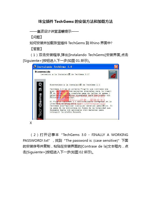
珠宝插件TechGems的安装方法和加载方法——皇波设计讲堂温馨提示——【问题】如何安装并加载珠宝插件TechGems到Rhino界面中?【答案】(1)双击安装程序,弹出[Instalando T echGems]安装界面,点击[Siguiente>]按钮进入下一步(如图01所示)。
X(2)打开记事本“TechGems 3.0 - FINALLY A WORKING PASSWORD!.txt”,找到“The password is: (case sensitive)”下面的安装序号并复制,粘贴在安装界面的[Contrase de la]文本框内,点击[Siguiente>]按钮进入下一步(如图02所示)。
(3)勾选“Acepto los t...”选项同意安装协议,再点击[Siguiente>]按钮进入下一步(如图03所示)。
(4)默认安装路径为:C:\TechGems,再点击[Siguiente>]按钮进入下一步(如图04所示)。
(5)进入安装状态(如图05所示),等到安装完成后再关闭安装界面,然后就可以开始加载到Rhino中。
(6)启动Rhino软件,下面开始在Rhino中加载TechGems。
菜单栏中的[Tools(工具)],在弹出的下拉菜单中选择[Toolbar Layout…(工具列配置)](如图06所示),弹出[Toolbars(工具列)]对话框,单击[File(文件)]按扭,在下拉菜单中选取[Open(打开)](如图07所示)。
(7)弹出[Open Toolbar Collection(打开工具列集)]对话框,在[查找范围(I)]下拉键中找到插件的路径文件“C\TechGems”,即查找C盘的“TechGems”文件夹;再选取该文件夹中的“TechGems_30_mm_en.tb”文件(如图08所示),单击[打开]按扭,[Toolbars(工具列)]对话框中显示出“TechGems_30_mm_en.tb”工具,此时Rhino的界面上显示出[TechGems English mm]的命令按扭。
- 1、下载文档前请自行甄别文档内容的完整性,平台不提供额外的编辑、内容补充、找答案等附加服务。
- 2、"仅部分预览"的文档,不可在线预览部分如存在完整性等问题,可反馈申请退款(可完整预览的文档不适用该条件!)。
- 3、如文档侵犯您的权益,请联系客服反馈,我们会尽快为您处理(人工客服工作时间:9:00-18:30)。
课程设计报告多核全系统模拟器GEMS分析班级:学号:姓名:2011年7月1 目的和背景由于单核处理器的处理能力已经接近极限,很难再有提高,多核处理器体系结构应运而生。
在处理器体系结构的设计中,由于用硬件做测试投资大,且不便于设计,不具有多次性,因此体系结构软件仿真技术是研究中的一门新技术。
而多核全系统模拟器GEMS/Simics框架能够模拟单核处理器、并行式多处理器、阵列式处理器等体系机构。
故本此课设选用构建GEMS+Simics框架,先逐步介绍搭建GEMS+Simics的各个环节,然后初步的研究单核和多核运行时程序在每个CPU中的运行情况,分析模拟器的构成及各部分的功能及性能分析。
2 安装流程2.1软件准备1) 在Ubuntu的官方网站上获得32位的Ubuntu10.042) 由于GEMS是开源软件首先在https:///gems/registercgi下进行注册,然后再在https:///gems/download.html下进行下载3)下载Simics时麻烦一些,先在https:///register/register.php地址上进行注册,而且必须作为学生或教职员工注册,然后申请免费的license。
4) 在/ubuntu/pool/main/z/zlib/网站上下载和自己的系统配套的zlib1g_1.2.3.3.dfsg-15ubuntu1_i386.deb和zlib1g-dev_1.2.3.3.dfsg-15ubuntu1_i386.deb5) 在/index2/unixsystem/Solaris/sol-10-u2-ga-sparc-v4/或者/us/sun/index.htm或者在网站上获得Soloris ,建议使用前者2.2安装Ubuntu此处不建议使用虚拟机安装,因为会影响到后面的安装,如果有CD/DVD可以直接用CD/DVD安装;也可以用USB或硬盘安装;最简单的是虚拟光驱wubi安装,但磁盘空间最大只能为30G,虽然之后可以用LVPM工具进行扩充,但不建议使用,因为速度很慢,且容易出错。
最好采用CD/DVD安装。
2.3GEMS/Simics安装1) 安装必要的工具s udo apt-get updatesudo apt-get install build-essentialsudo apt-get install bisonsudo apt-get install flexsudo dpkg –-install zlib1g_1.2.3.3.dfsg-7ubuntu1_i386.debsudo dpkg –-install zlib1g-dev_1.2.3.3.dfsg-7ubuntu1_i386.deb2) 在$HOME/.profile设置环境变量,必须保证路径是你想要装入GEMS和Simics 安装的位置的路径export GEMS=/home/so/gemsexport SIMICS_INSTALL=$GEMS/simics-3.0.31export SIMICS_EXTRA_LIB=./modulesexport PYTHONPA TH=./modules重启机器,否则全局变量不能起作用,会影响后面的安装,导致路径不对3) 安装GEMS:在home目录的so用户里面创建gems文件,将gems-release2.tar.gz复制到gems中,执行如下命令安装:tar xvzf gems-release2.tar.gzcp -r $GEMS/gems-2.0/* $GEMSr m -r $GEMS/gems-2.04) 将simics-pal-3.0.31-linux.tar 复制到$GEMS 文件中,执行如下命令安装Simics- 3.0.31:tar xvf $GEMS/simics-pal-3.0.31-linux.tarcd $GEMScd simics-3.0-install./install-simics.sh然后根据terminal的指示执行相应的指令并将license 复制到$GEMS/simics-3.0.31/licenses中5) 建立Simics 的工作站:cd $GEMSmkdir simics_3_workspacecd $SIMICS_INSTALL/bin./workspace-setup $GEMS/simics_3_workspace再根据相应的指示,用相应的指令建立工作站6) 编辑$GEMS/scripts/makesymlinks.sh文件,使其链接正确的$SIMICS_INSTALL 的路径cd $GEMS/scripts/vi makesymlinks.sh或gedit makesymlinks.sh(后者更好用一些)将echo "Making symlink for import directory.."之后修改为:. ln -s $SIMICS_INSTALL/import import7) 运行makesymlinks.shcd $GEMS/simics_3_workspace../scripts/makesymlinks.sh8) 将Simics 的工作站simics_3_workspace链接到$GEMS/simics.cd $GEMS/ln -s simics_3_workspace simics9) 修改GEMS 的配置文件Makefiles:将$GEMS/common/Makefile.simics_version的the version string值设置为 3.0,将$GEMS/common/mon中CC_VERSION修改为4.4.3,即为当前的的g++版本,可以通过在终端使用g++ -v指令获得当前系统的版本;将HOST_TYPE 的值改为:HOST_TYPE=x86-linux;将ifeq ($(SIMICS_VERSION),3.0)之后修改为SIMICS_ROOT := $(GEMS_ROOT)/simicsSIMICS_INCLUDE_ROOT := $(SIMICS_INSTALL)/src/include修改$GEMS/ruby/module/Makefile中的HOST_TYPE=x86-linux,使用Simics-3.0相应的GEMS_ROOT定义,注掉Simics 2.X的那行,修改CC_VERSION=4.4.3 修改$GEMS/opal/module/Makefile设置HOST_TYPE=x86-linux,注释掉Simics 2.X 的定义, 解注Simics 3.0的相应定义,修改CC_VERSION=4.4.3进入目录$GEMS/tourmaline/module/Makefile,修改CC_VERSION=4.4.3,设置HOST_TYPE=x86-linux10)编译Rubycd $GEMS/rubymake PROTOCOL=MOSI_SMP_bcast DESTINA TION=MOSI_SMP_bcast11)编译Opalcd $GEMS/opalmake module DESTINATION=MOSI_SMP_bcast2.4Solaris安装1)下载下列文件sol-10-u2-ga-sparc-v1.iso;sol-10-u2-ga-sparc-v2.iso;sol-10-u2-ga-sparc-v3.iso;sol-10-u2-ga-sparc-v4.iso;sol-10-u2-ga-sparc-v5.iso;2)安装Solaris修改$GEMS/simics-3.0.31//targets/serengeti中的abisko-sol10_cd-install1.simics,在if not defined cdrom_path 后面修改$cdrom_path=―$GEMS/Solaris/sol-10-u2-ga-sparc-v1.iso_path‖修改abisko-sol10_cd-install2.simics,在while $idx < 6 后面修改$cdrom_path[$idx] = (―sol-10-u2-ga-sparc-v‖ + $idx + ―.iso‖)3)执行如下指令,开始安装:cd $GEMS/simics-3.0.31/bin./simics $GEMS/simics-3.0.31/targets/serengeti/abisko-sol10-cd-install1.simics 当终端里提示“now exit simics and continue with the abisko-sol10-cd-install2.simics”时, 输入命令exit, 退出simics,再次在终端窗口输入命令./simics $GEMS/simics-3.0.31/targets/serengeti/abisko-sol10-cd-install2.simics当终端提示出现“now exit simics and continue with the abisko-sol10-cd-install3.simics”时, 输入命令exit, 退出,再次输入命令./simics ../targets/serengeti/abisko-sol10-cd-install3.simics编译完成后simics> exit4) 启动simics修改../targets/serengti/abisko-setup.include将第一句改为if not defined os {$os = “solaris10”}./simics -x tartgets/serengeti/abisko-common.simicssimics〉continue2.5加载,配置ruby和opal1) 配置simics./simics –stallsimics> instruction-fetch-mode instruction-fetch-tracesimics> istc-disablesimics> dstc-disablesimics> cpu-switch-time 1simics> read-configuration file.simics_path2) 加载ruby 和opalsimics> load-module rubysimics> load-module opal //一般不需要加载opal3) 配置ruby 和opalruby0.setparam g_NUM_PROCESSORS 1ruby0.setparam g_MEMORY_SIZE_BYTES 4294967296ruby0.initopal0.init4)运行ruby和opalruby0.dump-statsopal0.sim-step 10000000000opal0.listparamopal0.stats3安装时遇到的问题3.1安装GEMS/Simics时遇到的问题1)在安装GEMS与Simics时,必须保证在设置环境变量之后启动机器,否则在执行到编译Ruby和Opal时,会出现错误如下:make[1]: *** No rule to make target `simics/api.h',2)在$GEMS/common/mon中不仅仅要修改参数,还要改变指定的编译器,最开始遇到的错误为:make[2]: /s/gcc-3.4.1/bin/g++: Command not foundmake[2]: *** [x86-linux/obj/parser.o] Error 127make[2]: Leaving directory `/home/yanjun/gems/slicc'后来发现,是$GEMS/common/mon中配置的问题,将ifeq之后的语句改成下面的形式,选择/usr/bin/g++为编译器,而不是/s/gcc-4.4.3/bin/g++,因为后者路径不可达ifeq ($(HOST_TYPE),x86-linux)#CC = /s/gcc-4.4.3/bin/g++CC = /usr/bin/g++OPT_FLAGS = -march=i686LDFLAGS += -ggdb -g33)编译Ruby时遇到的错误及解决方案在遇到CacheMemory.h报错时,应该在CacheMemory.h引入库"string.h"在遇到Debug.C报错时,也应该在Debug.C引入库"string.h"遇到log_tm/LazyTransactionV ersionManager.C: In member function ‗voidLazyTransactionV ersionManager::issueWriteRequests(int)‘:log_tm/LazyTransactionV ersionManager.C:284: error: redefinition of‘Address request_address‘log_tm/LazyTransactionV ersionManager.C:283: error: ‗Addressrequest_address‘ previously declared here发现函数中是这样写的CacheMsg storeMsg(Address(request_address),Address(request_address),CacheRequestType_ST_XACT,SIMICS_get_program_counter(getLogicalProcID(thread)),AccessModeType_UserMode,g_DATA_BLOCK_BYTES,PrefetchBit_No,0,Address(0),thread,g_eventQueue_ptr->getTime(),should_escape);因此报错,故改为Address arg1Address = Address(request_address);Address arg2Address = Address(request_address);CacheMsg storeMsg(arg1Address,arg2Address,CacheRequestType_ST_XACT,SIMICS_get_program_counter(getLogicalProcID(thread)),AccessModeType_UserMode,g_DATA_BLOCK_BYTES,PrefetchBit_No,0,Address(0),thread,g_eventQueue_ptr->getTime(),should_escape);4)编译Opal时的错误system/simdist12.C: In function ‗void* mm_malloc(size_t, size_t, const char*, const char*, int, int)‘:system/simdist12.C:548: error: declaration of C function ‗void* mm_malloc(size_t, size_t, const char*, const char*, int, int)‘ conflicts with/home/yanjun/gems/simics-3.0.31/src/include/simics/util/alloc.h:60: error: previous declaration ‗void* mm_malloc(size_t, size_t, const char*, const char*, int)‘ here system/simdist12.C: In function ‗void* mm_zalloc(size_t, size_t, const char*, const char*, int, int)‘:system/simdist12.C:554: error: declaration of C function ‗void* mm_zalloc(size_t, size_t, const char*, const char*, int, int)‘ conflicts with/home/yanjun/gems/simics-3.0.31/src/include/simics/util/alloc.h:64: error: previous declaration ‗void* mm_zalloc(size_t, size_t, const char*, const char*, int)‘ here system/simdist12.C: In function ‗char* mm_strdup(const char*, const char*, int, int)‘:system/simdist12.C:559: error: declaration of C function ‗char* mm_strdup(const char*, const char*, int, int)‘ conflicts with/home/yanjun/gems/simics-3.0.31/src/include/simics/util/alloc.h:74: error: previous declaration ‗char* mm_strdup(const char*, const char*, int)‘ heresystem/simdist12.C: In function ‗void* mm_realloc(void*, size_t, size_t, const char*, const char*, int, int)‘:system/simdist12.C:571: error: declaration of C function ‗void* mm_realloc(void*, size_t, size_t, const char*, const char*, int, int)‘ conflicts with/home/yanjun/gems/simics-3.0.31/src/include/simics/util/alloc.h:66: error: previous declaration ‗void* mm_realloc(void*, size_t, size_t, const char*, const char*, int)‘ here 解决方案:可以将simdist12.C中的if 0改为if 1,或者将报错的函数都注掉3.2安装Solaris时遇到的问题1)安装Solaris时的错误,最初没有考虑到对虚拟机的空间利用率会这么大,所以在下载完Solaris的操作系统后意识到虚拟机容量不够,故又在外面挂接了一个磁盘,虚拟空间是90G,但实际最大可分配的空间也就是二十几吉而已,因为D盘中已经放了很多东西。
