第四篇第二章482-496
--贵州省煤矿安全生产管理制度编制指南(精)

贵州省煤矿安全生产管理制度编制指南贵州省煤矿安全生产管理制度编制指南 - 379 -第一章煤矿安全综合管理制度 - 380 -一.安全目标管理制度 - 380 -二.安全投入制度 - 381 -三.安全奖惩制度 - 382 -四.安全技术措施审批制度 - 383 -五.安全培训制度 - 385 -六.安全办公会议、制度 - 387 -七.安全检查制度 - 388 -八.事故隐患排查、治理、报告制度 - 389 -九.事故报告与责任追究制度 - 393 -十.煤矿入井检身与出入井人员清点制度 - 395 -十一.井下劳动组织定员制度 - 396 -十二.煤矿领导带班下井制度 - 397 -十三.安全生产标准化管理制度 - 400 -十四.安全生产群防群治制度 - 402 -十五.安全生产承诺制度 - 403 -十六.安全风险分级管控工作制度 - 404 -第二章煤矿地质测量工作制度 - 409 -十七.地质灾害防治技术管理制度 - 409 -十八.地质灾害预测预报制度 - 411 -十九.地质测量安全办公会议制度 - 413 -二十.地测资料、技术报告审批制度 - 414 -二十一.地测图纸审批、发放、回收、销毁制度 - 415 -二十二.地测资料收集、整理、定期分析、保管制度 - 417 -二十三.地质灾害普查制度 - 419 -第三章煤矿开采及顶板管理制度 - 421 -二十四.工作面顶板管理制度 - 421 -二十五.工作面支护质量检查制度 - 422 -二十六.工作面变化管理制度 - 423 -二十七.工作面机械设备检修保养制度 - 424 -二十八.乳化液泵站管理制度 - 425 -二十九.采煤工作面文明生产管理制度 - 426 -三十.采煤工作面支护材料设备配件备用制度 - 427 -三十一.掘进工程质量考核制度 - 428 -三十二.井巷维修制度 - 429 -三十三.敲帮问顶制度 - 430 -三十四.围岩观测制度 - 431 -第四章煤矿通风管理制度 - 433 -三十五.通风系统管理制度 - 433 -三十六.局部通风管理制度 - 435 -三十七.通风设施管理制度 - 437 -三十八.通风机无计划停风追查制度 - 439 -三十九.巷道贯通管理制度 - 440 -四十.井下测风管理制度 - 441 -四十一.盲巷和巷道启封管理制度 - 442 -四十二.反风演习管理制度 - 443 -第五章煤矿瓦斯管理制度 - 444 -四十三.瓦斯巡回检查制度 - 444 -四十四.瓦斯日报审查签字制度 - 447 -四十五.瓦斯检查工请示报告制度 - 449 -四十六.瓦斯检查工交接班制度 - 450 -四十七.瓦斯超限分析追查管理制度 - 451 -四十八.瓦斯排放管理制度 - 452 -四十九.瓦斯抽采管理制度 - 453 -五十.瓦斯等级鉴定管理制度 - 456 -第六章煤矿防尘管理制度 - 457 -五十一.综合防尘管理制度 - 457 -五十二.粉尘检测制度 - 458 -五十三.预防和隔绝煤尘爆炸管理制度 - 459 -第七章煤矿防治煤与瓦斯突出管理制度 - 460 -五十四.防突计划管理制度 - 460 -五十五.防突技术管理制度 - 461 -五十六.防突现场跟班制度 - 465 -五十七.防突措施督促检查制度 - 466 -五十八.防突工作保障制度 - 468 -第八章煤矿防灭火管理制度 - 469 -五十九.煤仓防火管理制度 - 469 -六十.矸石山防火管理制度 - 470 -六十一.木料场防火管理制度 - 471 -六十二.地面建(构)筑物防火管理制度 - 472 -六十三.自然发火预测预报管理制度 - 473 -六十四.注氮防灭火管理制度 - 475 -六十五.消防设施维护和保养制度 - 478 -六十六.电气焊审批制度 - 480 -六十七.火区管理制度 - 481 -第九章煤矿防治水管理制度 - 482 -六十八.水害防治技术管理制度 - 482 -六十九.水害预测预报制度 - 483 -七十.雨季巡视制度 - 484 -七十一.煤矿重大水患停产撤人制度 - 485 -七十二.雨季“三防”管理制度 - 487 -七十三.防治水安全确认制度 - 488 -第十章煤矿爆炸物品和井下爆破管理制度 - 489 -七十四.爆炸物品领退制度 - 489 -七十五.煤矿爆炸物品丢失处理办法 - 491 -七十六.“一炮三检”制度及“三人连锁”爆破制度 - 492 -第十一章煤矿运输提升管理制度 - 494 -七十七.运输设备运行、检修、检测管理制度 - 494 -七十八.运输安全设施检查、试验制度 - 496 -七十九.轨道线路检查、维修管理制度 - 497 -八十.辅助运输安全事故管理制度 - 498 -第十二章煤矿电气及监控、通信管理制度 - 499 -八十一.停送电管理制度 - 499 -八十二.设备设施检查、维修制度 - 501 -八十三.电气试验测试制度 - 503 -八十四.干部上岗检查制度 - 504 -八十五.设备管理制度 - 505 -八十六.机电事故统计分析制度 - 506 -八十七.防爆设备入井安装验收制度 - 507 -八十八.电缆管理制度 - 508 -八十九.小型电器管理制度 - 509 -九十.油脂管理制度 - 510 -九十一.机电配件管理制度 - 511 -九十二.阻燃胶带管理制度 - 513 -九十三.杂散电流管理制度 - 514 -九十四.钢丝绳管理制度 - 515 -九十五.设备包机管理制度 - 516 -九十六.交接班制度 - 517 -九十七.巡回检查制度 - 518 -九十八.保护试验制度 - 519 -九十九.要害场所管理制度 - 521 -一百.安全监控管理制度 - 522 -第十三章煤矿职业病危害防治管理制度 - 525 -一百零一.职业病危害防治责任制度 - 525 -一百零二.职业病危害警示与告知制度 - 528 -一百零三.职业病危害项目申报制度 - 530 -一百零四.职业病防治宣传.教育和培训制度 - 531 -一百零五.职业病防护设施管理制度 - 533 -一百零六.职业病个体防护用品管理制度 - 535 -一百零七.职业病危害日常监测及检测评价管理制度 - 537-一百零八.建设项目职业健康“三同时”管理制度 - 538 -一百零九.劳动者职业健康监护及其档案管理制度 - 539 -一百一十.职业病诊断、鉴定及报告制度 - 541 -一百一十一.职业病危害防治经费保障及使用管理制度 - 542 -一百一十二.职业卫生档案管理制度 - 543 -一百一十三.职业病危害事故应急管理制度 - 545 -第十四章煤矿应急救援管理制度 - 546 -一百一十四.事故监测与预警制度 - 546 -一百一十五.应急值守制度 - 549 -一百一十六.应急信息报告和传递制度 - 550 -一百一十七.应急投入及资源保障制度 - 553 -一百一十八.应急预案管理制度 - 555 -一百一十九.应急演练制度 - 556 -一百二十.应急救援队伍(兼职救护队)管理制度 - 557 -一百二十一.应急物资装备管理制度 - 560 -一百二十二.安全避险设施管理和使用制度 - 561 -一百二十三.应急资料档案管理制度 - 562 -第十五章煤矿调度和班组安全管理制度 - 563 -一百二十四.调度值班制度 - 563 -一百二十五.调度员交接班制度 - 564 -一百二十六.调度汇报制度 - 565 -一百二十七.信息汇总分析制度 - 566 -一百二十八.调度人员入井(坑)制度 - 567 -一百二十九.业务学习制度 - 568 -一百三十.事故和突发事件信息报告与处理制度 - 569 -一百三十一.调度文档管理制度 - 570 -一百三十二.班前.班后会和交接班制度 - 572 -一百三十三.班组安全生产标准化和文明生产管理制度 - 573 -一百三十四.班组学习制度 - 574 -一百三十五.民主管理班务公开制度 - 575 -一百三十六.安全绩效考核制度 - 576 -贵州省煤矿安全生产管理制度编制指南第一章煤矿安全综合管理制度一.安全目标管理制度(一)为抓好煤矿安全生产管理,实现预定的安全生产与职业病危害防治目标,确保安全生产,根据《煤矿安全规程》(2016)第4条“煤矿企业必须建立健全安全生产与职业病危害防治目标管理、投入、奖惩、技术措施审批、培训、办公会议制度,安全检查制度,事故隐患排查、治理、报告制度,事故报告与责任追究制度等”的规定,制定本制度。
第四章不法的秘密权势
第四章:不法的秘密权势从启示而来,而非从交流得来的知识,是我们免被引诱的最好防卫圣经中常常提到“末世”这个词。
在人类历史中,现今很可能是最令人振奋,也是最为使人恐惧的时代。
令人兴奋是因为我们可能会见证上帝最大的启示,关于上帝荣耀的启示,这是过去的任何世代从未体验过的,随之而来的还有难以想象的灵魂大收割。
这是一个荣耀与喜乐的时代,也是审判与恐惧的时代。
可怕是因为使徒保罗明确地告诉我们:“在末世必有危险的日子来到。
”(提后3:1)在这一陈述之前,他说道:“你该知道”。
换句话说,要特别注意留心我接下来所写的,在你自己的脑海中要予以强调,要给予重视的。
他然后在第三章详细地讲述了这个险境。
这个可怕的日子并不是因政府或者无神论者的逼迫而起。
这个危险的时代是由于教会中普遍存在的欺骗而引起的。
整篇的新约圣经不断在重复着这一警告。
欺骗是一个令人恐慌的东西。
为什么?因为它是欺骗人的!一个被欺骗的人会全心地相信自己是正确的,但事实上他是错误的。
耶稣在福音书中不断警告我们,要抵挡欺骗。
单单在马太福音24章里,祂就四次警告我们要当心欺骗。
实际上,当祂的门徒问到祂的再来的时候,祂在描述我们的日子时口中说出的第一句话是:“你们要谨慎,免得有人迷惑[欺骗]你们。
”(太24:4)我们很容易感受到祂警告的紧迫性。
祂的语气认真而严肃。
祂要这些话印刻在他们的灵魂上,并永远摆在他们的面前。
祂的话语立定在天,直到永远,我们如果聪明的话就不要忽略祂的劝告。
两个重要的问题我们必须问两个重要的问题。
首先,这种迷惑的根本原因是什么?第二,为什么这种迷惑能够不受约束地运作呢?要回答第一个问题,这种迷惑的根本原因无非正是我们在前几章讨论过的,对上帝权柄的不顺服,或者说不法。
我们被告诫:“只是你们要行道,不要单单听道,自己欺哄[欺骗]自己”(雅1:22)。
要清醒啊!圣经告诉我们,如果一个人听到上帝的话却不遵行的话,迷惑就进入了他的心灵和头脑。
这样的人生活在这样一种坚定的信念之下,他确信自己都是正确的,但实际上却是在错误之中。
贵州省煤矿安全生产管理制度编制指南
贵州省煤矿安全生产管理制度编制指南贵州省煤矿安全生产管理制度编制指南 -379 -第一章煤矿安全综合管理制度 -380 -一.安全目标管理制度 -380 -二.安全投入制度 -381 -三.安全奖惩制度 -382 -四.安全技术措施审批制度 -383 -五.安全培训制度 -385 -六.安全办公会议、制度 -387 -七.安全检查制度 -388 -八.安全事故隐患排查、治理、报告制度 -389 -九.事故报告与责任追究制度 -393 -十.煤矿入井检身与出入井人员清点制度 -395 -十一.井下劳动组织定员制度 -396 -十二.煤矿领导带班下井制度 -397 -十三.安全生产标准化管理制度 -400 -十四.安全生产群防群治制度 -402 -十五.安全生产承诺制度 -403 -十六.安全风险分级管控规章管理制度 -404 -第二章煤矿地质测量规章管理制度 -409 -十七.地质灾害防治技术管理制度 -409 -十八.地质灾害预测预报制度 -411 -十九.地质测量安全办公会议制度 -413 -二十.地测资料、技术报告审批制度 -414 -二十一.地测图纸审批、发放、回收、销毁制度 -415 -二十二.地测资料收集、整理、定期分析、保管制度 -417 -二十三.地质灾害普查制度 -419 -第三章煤矿开采及顶板管理制度 -421 -二十四.工作面顶板管理制度 -421 -二十五.工作面支护质量检查制度 -422 -二十六.工作面变化管理制度 -423 -二十七.工作面机械设备检测修理保养制度 -424 -二十八.乳化液泵站管理制度 -425 -二十九.采煤工作面文明生产管理制度 -426 -三十.采煤工作面支护材料设备配件备用制度 -427 -三十一.掘进工程质量考核管理细则 -428 -三十二.井巷维修制度 -429 -三十三.敲帮问顶制度 -430 -三十四.围岩观测制度 -431 -第四章煤矿通风管理制度 -433 -三十五.通风系统管理制度 -433 -三十六.局部通风管理制度 -435 -三十七.通风设施管理制度 -437 -三十八.通风机无计划停风追查制度 -439 -三十九.巷道贯通管理制度 -440 -四十.井下测风管理制度 -441 -四十一.盲巷和巷道启封管理制度 -442 -四十二.反风演习管理制度 -443 -第五章煤矿瓦斯管理制度 -444 -四十三.瓦斯巡检制度 -444 -四十四.瓦斯日报审查签字制度 -447 -四十五.瓦斯检查工请示报告制度 -449 -四十六.瓦斯检查工交接班制度 -450 -四十七.瓦斯超限分析追查管理制度 -451 -四十八.瓦斯排放管理制度 -452 -四十九.瓦斯抽采管理制度 -453 -五十.瓦斯等级鉴定管理制度 -456 -第六章煤矿防尘管理制度 -457 -五十一.综合防尘管理制度 -457 -五十二.粉尘检测制度 -458 -五十三.预防和隔绝煤尘爆炸管理制度 -459 -第七章煤矿防治煤与瓦斯突出管理制度 -460 -五十四.防突计划管理制度 -460 -五十五.防突技术管理制度 -461 -五十六.防突现场跟班制度 -465 -五十七.防突措施督促检查制度 -466 -五十八.防突工作保障制度 -468 -第八章煤矿防灭火管理制度 -469 -五十九.煤仓防火管理制度 -469 -六十.矸石山防火管理制度 -470 -六十一.木料场防火管理制度 -471 -六十二.地面建(构)筑物防火管理制度 -472 -六十三.自然发火预测预报管理制度 -473 -六十四.注氮防灭火管理制度 -475 -六十五.消防设施维护和保养制度 -478 -六十六.电气焊审批制度 -480 -六十七.火区管理制度 -481 -第九章煤矿防治水管理制度 -482 -六十八.水害防治技术管理制度 -482 -六十九.水害预测预报制度 -483 -七十.雨季巡视制度 -484 -七十一.煤矿重大水患停产撤人制度 -485 -七十二.雨季“三防”管理制度 -487 -七十三.防治水安全确认制度 -488 -第十章煤矿爆炸物品和井下爆破管理制度 -489 -七十四.爆炸物品领退制度 -489 -七十五.煤矿爆炸物品丢失处理办法 -491 -七十六.“一炮三检”制度及“三人连锁”爆破制度 -492 -第十一章煤矿运输提升管理制度 -494 -七十七.运输设备运转、检测修理、检测管理制度 -494 -七十八.运输安全设施检查、试验制度 -496 -七十九.轨道线路检查、维修管理制度 -497 -八十.辅助运输安全事故管理制度 -498 -第十二章煤矿电气及监控、通信管理制度 -499 -八十一.停送电管理制度 -499 -八十二.设备设施检查、维修制度 -501 -八十三.电气试验测试制度 -503 -八十四.干部上岗检查制度 -504 -八十五.设备管理制度 -505 -八十六.机电事故统计分析制度 -506 -八十七.防爆设备入井安装验收制度 -507 -八十八.电缆管理制度 -508 -八十九.小型电器管理制度 -509 -九十.油脂管理制度 -510 -九十一.机电配件管理制度 -511 -九十二.阻燃胶带管理制度 -513 -九十三.杂散电流管理制度 -514 -九十四.钢丝绳管理制度 -515 -九十五.设备包机管理制度 -516 -九十六.交接班制度 -517 -九十七.巡检制度 -518 -九十八.保护试验制度 -519 -九十九.要害场所管理制度 -521 -一百.安全监控管理制度 -522 -第十三章煤矿职业病危害防治管理制度 -525 -一百零一.职业病危害防治责任制度 -525 -一百零二.职业病危害警示与告知制度 -528 -一百零三.职业病危害项目申报制度 -530 -一百零四.职业病防治宣传.教育和培训制度 -531 -一百零五.职业病防护设施管理制度 -533 -一百零六.职业病个人防护用品管理制度 -535 -一百零七.职业病危害日常监测及检测评价管理制度 -537 -一百零八.建设项目职业健康“三同时”管理制度 -538 -一百零九.劳动者职业健康监护及其档案管理制度 -539 -一百一十.职业病诊断、鉴定及报告制度 -541 -一百一十一.职业病危害防治经费保障及使用管理制度 -542 -一百一十二.职业卫生档案管理制度 -543 -一百一十三.职业病危害事故应急管理制度 -545 -第十四章煤矿应急救援管理制度 -546 -一百一十四.事故监测与预警制度 -546 -一百一十五.应急值守制度 -549 -一百一十六.应急信息报告和传递制度 -550 -一百一十七.应急投入及资源保障制度 -553 -一百一十八.应急预案管理制度 -555 -一百一十九.应急演习制度 -556 -一百二十.应急救援队伍(兼职救护队)管理制度 -557 -一百二十一.应急物资装备管理制度 -560 -一百二十二.安全避险设施管理和使用制度 -561 -一百二十三.应急资料档案管理制度 -562 -第十五章煤矿调度和班组安全管理制度 -563 -一百二十四.调度值班制度 -563 -一百二十五.调度员交接班制度 -564 -一百二十六.调度汇报制度 -565 -一百二十七.信息汇总分析制度 -566 -一百二十八.调度人员入井(坑)制度 -567 -一百二十九.业务学习制度 -568 -一百三十.事故和突发状况信息报告与处理制度 -569 -一百三十一.调度文档管理制度 -570 -一百三十二.班前.班后会和交接班制度 -572 -一百三十三.班组安全生产标准化和文明生产管理制度 -573 -一百三十四.班组学习制度 -574 -一百三十五.民主管理班务公开制度 -575 -一百三十六.安全绩效考核管理细则 -576 -贵州省煤矿安全生产管理制度编制指南第一章煤矿安全综合管理制度一.安全目标管理制度(一)为强抓煤矿安全生产管理,实现预定的安全生产与职业病危害防治目标,确保安全有序生产,依据《煤矿安全规程》(2016)第4条“煤矿企业必须建立健全的安全生产与职业病危害防治目标管理、投入、奖惩、技术措施审批、培训、办公会议制度,安全检查制度,安全事故隐患排查、治理、报告制度,事故报告与责任追究制度等”的有关规定,特制定本项制度。
消防工程师2020年新旧教材对比

第三篇
2019版教材
2020版教材
P285,(三)全淹没应用方 式的开式系 统的防护区容积
P365,(三)全淹没应用方式的开式系统 的防护区容积
采用全淹没应用方式的开式系统,其单个 防护区的容
采用全淹没应用方式的开式
系统,其单个 防护区的容积, 积,泵组系统不宜大于 3000m2,瓶组系统不宜超过
➢ 综合能力
主要修订《火灾自动报警系统施工验收标准》GB50166-2019、增加《大型商业综合体消
防安全管理规定》《社会单位灭火和应急疏散预案》GB/T38315、《关于深化消防执法改 革的意见》、《消防技术服务机构从业条件》
第一篇:消防法及相关法律法规与消防职业道德(改动4处) 第二篇:建筑防火(改动4处) 第三篇:消防设施安装、检测及维护管理(主要改动聚集在第三篇-十四
p285消防用水量计算:
2019版教
第三篇
材
建筑消 防设施
2020版教材
P320新增:特殊类型洒水喷头,包括以下几种喷头:干式直立酒水喷 头,它是由专用管段和安装于管段出口的洒水喷头组成的组件。在管 段入口设有密封机构,在洒水喷头动作前,此密封机构可阻止水进入 管段。齐平式洒水喷头,即部分或全部本体(包括根部螺纹)安装在吊 顶下平面以上,但热敏感元件的集热部分全部处于吊顶下平面以下的 酒水喷头。嵌入式酒水喷头,即全部或部分本体被安装在嵌入吊顶的 护罩内的酒水喷头。隐蔽式洒水喷头,即带有装饰盖板的嵌入式酒水 喷头。带涂层酒水喷头,即带有防腐作用或装饰作用的涂层或镀层的 洒水喷头。带防水罩酒水喷头,是指带有固定于热敏感元件上方的防
2020版教材
消防法 及相关 法律法 规与消 防职业
《基督山伯爵》章节分享 第二章 父与子

《基督山伯爵》第二章父与子我们暂且先放下不谈腾格拉尔如何怀着仇恨,竭力在船主莫雷尔的耳边讲他的同伴的坏话的。
且说唐太斯横过了卡纳比埃尔街,顺着诺埃尹街转入梅兰巷,走进了靠左边的一家小房子里。
他在黑暗的楼梯上一手扶着栏杆,一手按在他那狂跳的心上,急急地奔上了四层楼梯。
他在一扇半开半掩的门前停了下来,那半开的门里是一个小房间。
唐太斯的父亲就住在这个房间里。
法老号到港的消息老人还不知道。
这时他正踩在一张椅子上,用颤抖的手指在窗口绑扎牵牛花和萎草花,想编成一个花棚。
突然他觉得一只手臂拦腰抱住了他,随即一个熟悉的声音在耳边喊起来,“父亲!亲爱的父亲!”老人惊叫了一声,转过身来,一看是自己的儿子,就颤巍巍地脸色惨白地倒在了他的怀抱中。
“你怎么啦,我最亲爱的父亲!你病了吗?”青年吃惊地问。
“不,不,我亲爱的爱德蒙——我的孩子——我的宝贝!不,我没想到你回来了。
我真太高兴了,这样突然的看见你太让我激动了——天哪,我觉得我都快要死了。
”“高兴点,亲爱的父亲!是我——真的是我!人们都说高兴绝不会有伤身体的,所以我就偷偷的溜了进来。
嗨!对我笑笑,不要拿这种疑惑的眼光看我呀。
是我回来啦,我们现在要过快活的日子了。
”“孩子,我们要过快活的日子,——我们要过快活的日子,”老人说道。
“但我们怎么才能快活呢?难道你会永远不再离开我了吗?来,快告诉我你交了什么好运了?”“愿上帝宽恕我:我的幸福是建立在另一家人丧亲的痛苦上的,但上帝知道我并不是自己要这样的。
事情既然已经发生了,我实在无法装出那种悲哀的样子。
父亲,我们那位好心的船长莱克勒先生他死了,承蒙莫雷尔先生的推荐,我极有可能接替他的位置。
你懂吗,父亲?想想看,我二十岁就能当上船长,薪水是一百金路易[法国金币名。
],还可以分红利!这可是象我这样的穷水手以前连想都不敢想的呀。
”“是的,我亲爱的孩子,”老人回答说,——“是的,这真是一桩大喜事的。
”“嗯,等我拿到第一笔钱时,我就为你买一所房子,要带花园的,你可以在里面种种牵牛花,萎草花和皂荚花什么的。
家庭教育圣经-人生卷下-第二章

第二章以邪招报以邪召邪陈云亭舍人言:有台湾驿使宿馆舍,见艳女登墙下窥,叱索无所睹。
夜半琅然有声,乃片瓦掷枕畔。
叱问是何妖魅,敢侮天使?窗外朗应曰:“公禄命重,我避公不及,致公叱索,惧干神谴,惴惴至今。
今公睡中萌邪念,误作驿卒之女,谋他日纳为妾。
人心一动,鬼神知之。
以邪召邪,神不得而咎我,故投瓦相报。
公何怒焉?”驿使大愧沮,未及天曙,促装去。
【译文】舍人陈云亭说:有位奉命去台湾的使臣,途中住在驿站的馆舍里。
忽然发现有个艳丽的女子扒在墙头往院里窥探,便加以怒斥,他出至外面搜索,却一无所获。
睡到半夜,忽然哐当一声,有一瓦片飞落在他枕边。
使臣大怒,大声喝问道:“何方妖怪,胆敢侮弄天子的使臣?”只听窗外一个女子朗声答道:“你禄命大,白天我一时回避不及,冲撞了你,惹你又是呵斥,又是搜索。
我害怕这事被神明察觉,可吃罪不起,心里一直惴惴不安。
可是你刚才睡在床上,却胡思乱想,心生邪念,把我当做那驿站里老兵的女儿,打算如何耍手段,娶来做你的小老婆。
可你哪里知道,只要人心里的念头一动,鬼神立刻就知道了。
人有邪心,必会招来邪鬼的骚扰,就是神明知道了也不会加于责备。
因此我就投一块瓦片给你作为相报,你这有什么可恼火的?”使臣听了,心里又惭愧又沮丧,等不及天亮,就命仆人收拾行装,离开这馆舍。
巧舌罚哑王孝廉金英言:江宁一书生,宿故家废园中。
月夜,有艳女窥窗。
心知非鬼即狐,爱其姣丽,亦不畏怖。
招使入室,即宛转相就。
然始终无一语,问亦不答,惟含笑流盼而已。
如是月余,莫喻其故。
一日,执而固问之。
乃取笔作字曰:“妾前明某翰林侍姬,不幸夭逝。
因平生巧于谗构,使一门骨肉如水火。
冥司见谴,罚为喑鬼,已沉沦二百余年。
君能为书《金刚经》十部,得仗佛力,超拔苦海,则世世衔感矣。
”书生如其所乞。
写竣之日,诣书生再拜,仍取笔作字曰:“借金经忏悔,已脱离鬼趣,然前生罪重,仅能带业往生,尚须三世作哑妇,方能语也。
”【译文】举人王金英说:江宁有位书生,住宿在某官宦人家的废花园里。
经典神话故事-第2章
第2章人类的时代神-创造的第一代人类乃是黄金的一代。
那时候统治天国的是克洛诺斯(即萨图恩)。
这代人生活得如同神-一样,他们无忧无虑,没有繁重的劳动,也没有苦恼和贫困。
大地给他们提供了各种各样的硕果,丰盛的草地上牛羊成群,他们平和地从事劳动,几乎不会衰老。
当他们感到死期来临的时候,便沉入安详的长眠之中。
当命运之神判定黄金的一代人从地上消失时,他们都成为仁慈的保护神,在云雾中来来去去,他们是一切善举的施主,维护法律和正义,惩罚一切罪恶。
后来神-用白银创造了第二代人类。
他们在外貌和津神上都与第一代人类不同。
娇生惯养的孩子生活在家中,受到母亲的溺爱和照料。
他们百年都保持着童年,津神上不成熟。
等到孩子步入壮年时,他们的一生只剩下短短的几年了。
放肆的行为使这代人陷入苦难的深渊,因为他们无法节制他们的激烈的感情。
他们尔虞我诈,肆无忌惮地违法乱纪,不再给神-献祭。
宙斯十分恼怒,要把这个种族从地上消灭,因为他不愿意看到有人亵渎神。
当然,这个种族也不是一无是处,所以他们荣幸地获得恩准,在终止生命以后,可以作为魔鬼在地上漫游。
天父宙斯创造了第三代人类。
即青铜的人类。
这代人跟白银时代的人又完全不同。
他们残忍而粗暴,只知道战争,总是互相厮杀。
每个人都要千方百计地侮辱其他人。
他们专吃动物的肉,不愿食用田野上的各种果实。
他们顽固的意志如同金刚石一样坚硬,人也长得异常高大壮实。
他们使用的是青铜武器,住的是青铜房屋,用青铜农具耕种田地,因为那时还没有铁。
他们不断进行战争,可是,虽然他们长得高大可怕,然而却无法抗拒死亡。
他们离开晴朗而光明的大地之后,便降入陰森可怕的冥府之中。
当这代人也降入地府时,宙斯又创造了第四代人。
这代人应该住在肥沃的大地上,他们比以前的人类更高尚,更公正。
他们是神-英雄的一代人,即古代所称的半神的英雄们。
可是最后他们也陷入战争和仇杀中,有的为了夺取俄狄甫斯国王的国土,倒在底比斯的七道城门前;有的为了美丽的海轮跨上战船,倒在特洛伊的田野上。
化学专业本科毕业论文(DOC)

摘要取代芳香酰肼化合物具有抗菌、止痛、降血压、抗结核、抗肿瘤等多方面的生物活性。
本文以苯甲酸、苯并三氮唑、二氯亚砜及水合肼等为原料,经两步反应合成了目标产物取代芳香酰肼。
对合成目标产物的结构经IR,MS进行了确证。
关键词:苯甲酸;苯并三氮唑;水合肼;合成ABSTRACThydrazide compounds exhibit wide spread biological activities such as analgesic, hypotensive, antibacterial, antituberculous, anti-tumor and so on. In this thesis, replace the aromatic hydrazide compounds were synthesized using aromatic acid, 1H-Benzotriazole, 2chloro sulfoxide and hydrazine hydrate as raw materials by two-steps reaction. The structure of title compound was confirmed by IR, MS.Key words: replace the aromatic hydrazide; aromatic acid; 1H-Benzotriazole;2chloro sulfoxide; synthesis目录摘要 .............................................................................................................................................. ABSTRACT.. (i)第一章前言 ......................................................................................................................... - 0 - 芳香酰肼类衍生物生物活性的研究.................................................................................. - 0 - 芳香酰肼类衍生物抗菌活性的研究.......................................................................... - 0 -芳香酰肼类衍生物抗肿瘤活性的研究...................................................................... - 2 -芳香酰肼类衍生物合成绿色新农药的研究.............................................................. - 3 -1.2 芳香酰肼合成方法的研究进展................................................................................... - 4 -酯与水合肼反应合成酰肼.......................................................................................... - 4 -苯甲酰氯与肼溶液反应合成酰肼.............................................................................. - 4 -氨基保护法.................................................................................................................. - 5 - 本课题的提出...................................................................................................................... - 6 - 第二章实验部分 ................................................................................................................. - 7 - 仪器与试剂.......................................................................................................................... - 7 -2.2 实验方法..................................................................................................................... - 8 -2.2.1 实验准备........................................................................................................ - 8 -2.2.2 化合物苯甲酰基苯幷三氮唑的制备.............................................................. - 8 -2.2.3 取代芳香酰肼的制备...................................................................................... - 9 -产物的表征.................................................................................................................. - 9 - 第三章结果与讨论 ............................................................................................................... - 9 - 取代芳香酰肼的合成方法的改良.................................................................................... - 10 - 目标产物酰肼合成条件的优化........................................................................................ - 10 -3.2.1 物料比对芳香酰肼的产率的影响................................................................ - 10 -反应时间对芳香酰肼产率的影响............................................................................ - 11 - 第四章结论 ......................................................................................................................... - 12 - 参考文献 ............................................................................................................................. - 13 - 致谢 ............................................................................................................ 错误!未定义书签。
历代上6章逐节解释

历代上6章逐节解释全文共四篇示例,供读者参考第一篇示例:历代上是《旧约圣经》中的一本书,它记录了以色列列王的历史,从大卫王即位开始到巴比伦王国的囚禁和重建圣殿。
这本书包含了许多重要的历史事件和人物,对于了解犹太历史和文化有着不可忽视的意义。
下面我们将逐章逐节解释《历代上》的前六章。
第一章是介绍大卫王即位和他的统治。
在此章节中,我们看到大卫是一个虔诚的上帝敬拜者,他希望建造一个永恒的殿宇供奉上帝。
尽管大卫未能实现这个目标,但他的意图表明他是上帝心目中一个合格的王者。
这一章还提到大卫对以色列的影响和他建立的国家的繁荣。
第二章继续探讨了大卫的王国和他的后代。
这一章节中,我们看到以色列列王的历史开始走向衰落,尽管有些国王信奉上帝,但也有些国王背离上帝的旨意。
这一章还提到了大卫的儿子所罗门的统治,以及所罗门建造的圣殿和他的智慧。
第三章描述了所罗门之后的列王的历史。
在这一章节中,我们看到以色列分裂成两个王国,分别是以色列王国和犹大王国。
这一章还提到了一些列王的恶行和上帝对他们的惩罚。
这一段历史向我们展示了上帝对忠心的信徒的眷顾,以及对不忠心的人的审判。
第四章继续描述了列王的历史,包括一些在犹大王国的国王和他们的行为。
这一章也提到了耶路撒冷的陷落和人民被掳的事件。
尽管上帝对列王和人民的警告,他们仍然不听从上帝的话语,导致他们遭受了严重的后果。
第五章继续探讨了犹大王国的历史,尤其是一些忠心的国王如希西家和约书亚。
这些国王信奉上帝,遵守上帝的律法,并试图恢复国家的道德和宗教生活。
希西家为以色列列王的繁荣和国家的复兴作出了重要的贡献。
第六章是最后一章,描述了犹大王国的末期和被掳的情况。
在这一章节中,我们看到犹大王国的毁灭和人民被俘虏到巴比伦。
尽管他们经历了艰难的时期,但这一段历史也为人们带来了对上帝的信任和盼望。
在这一章中,上帝向人们传达了对他们的怜悯和拯救的应许。
在《历代上》的前六章中,我们看到了以色列列王的历史和他们与上帝之间的关系。
福尔摩斯与赛马第二章主要内容

福尔摩斯与赛马第二章主要内容
摘要:
1.福尔摩斯与赛马的关系
2.第二章的主要内容概述
3.福尔摩斯在第二章中的表现
4.第二章故事情节的实用性
正文:
福尔摩斯,这位著名的侦探,以其敏锐的洞察力和高超的推理能力为人们所熟知。
而在福尔摩斯的故事中,赛马这一元素也占据了一席之地。
第二章的主要内容便围绕福尔摩斯与赛马展开,展现了福尔摩斯在侦探事业中的独特魅力。
在第二章中,福尔摩斯接到一个关于赛马比赛的案件。
某赛马俱乐部成员纷纷失踪,赛事组织者也陷入了困境。
福尔摩斯通过对赛事记录、马匹状况等方面的研究,发现了案件背后的线索。
他深入调查,揭开了组织者利用赛马进行非法活动的真相。
福尔摩斯在第二章中的表现可圈可点。
他运用了自己的专业知识,对赛马赛事的方方面面进行了分析。
通过对比赛马的奔跑速度、马匹的体能状况等数据,福尔摩斯找到了异常之处,从而顺藤摸瓜,找到了案件的真凶。
这体现了福尔摩斯在侦探工作中的严谨态度和敏锐洞察力。
第二章的故事情节具有较强的实用性。
福尔摩斯在破案过程中,不仅展现了出色的推理能力,还为读者提供了丰富的赛马知识。
这使得故事既具有趣味
性,又具有教育意义。
读者在阅读的过程中,不仅可以领略到福尔摩斯侦探的魅力,还能了解到赛马背后的故事。
总之,福尔摩斯与赛马的第二章,通过福尔摩斯的侦探才能和赛马知识的结合,为读者呈现了一个充满悬念和惊喜的故事。
在阅读过程中,读者不仅可以享受到侦探小说的快感,还能在福尔摩斯的智慧中汲取实用的赛马知识。
初级会计实务三色笔记

第二节产品成本计算的品种法484
第三节产品成本计算的分批法485
第四节产品成本计算的分步法487
第五节产品成本计算方法的综合运用496
第六节产品成本分析498
第十章事业单位会计基础504
第一章资产
本章应关注的问题:
(1)货币资金的核算;
(2)应收账款、存货的核算;
Hale Waihona Puke (3)金融资产的核算;(三)库存现金的账务处理
企业内部各部门、各单位周转使用的备用金,应在“其他应收款—备用金”账户核算,也可以单独设置“备用金”账户核算,不得在“库存现金”账户核算。
【提示】备用金是指为了满足企业内部各部门和职工个人生产经营活动的需要,而暂付给有关部门和人员使用的备用金。
【例题·单选题】下列关于现金管理说法不正确的()。
A.冲减管理费用
B.增加营业外收入
C.冲减财务费用
D.增加其他业务收入
【答案】B
【解析】无法査明原因的现金溢余,计入营业外收入。
二、银行存款
(一)银行存款的账务处理
企业可按开户银行和其他金融机构、存款种类等设置“银行存款日记账”,根据收付款凭证,按照业务的发生顺序逐笔登记。每日终了,应结出余额。
【相关链接】每日终了,也应当在现金日记账上结出余额。
第二节提供劳务收入307
第三节让渡资产使用权收入315
第五章费用329
第一节 营业成本330
第二节 营业税金及附加332
第三节 期间费用335
第六章利润340
第一节营业外收支346
第二节所得税费用(掌握计算和构成内容)353
第三节本年利润359
第七章 财务报告365
儿童急性白血病环境危险因素研究

专家论坛•儿童血液肿瘤儿童急性白血病环境危险因素研究伍巧微,甘文婷,朱璐,毛碧涛,钟淑玲,胡政斌,任晓娟,王玲,张辉,孙新基金项目:广州市科技计划项目(编号:201300000090);国家自然科学基金资助项目(编号:81300401)作者单位:510623广东,广州医科大学附属广州市妇女儿童医疗中心血液肿瘤科(伍巧微,甘文婷,朱璐,毛碧涛,钟淑玲,胡政斌,任晓娟,王玲,张辉,孙新);200092上海,上海交通大学医学院附属新华医院(孙新)作者简介:伍巧微(1994-),女,在读硕士研究生,研究方向:儿童白血病的诊治。
E-mait:156****5970@通讯作者:孙新(1966-),男,医学硕士,主任医师,硕士研究生导师,研究方向:儿童白血病的诊治。
E-mail:doctorsunxin@孙新,儿科学硕士,主任医师,广州医科大学硕士研究生导师;现任上海交通大学医学院附属新华医院副院长。
学术任职:广东省医院协会医务管理委员会副主任委员,广东省医疗安全协会质量与安全管理委员会副主任委员,广东省优生优育协会地中海贫血委员会副主任委员,广州市医学会儿科学分会第十一届委员会主任委员等。
任《中国小儿血液与肿瘤杂志》、《国际医药卫生导报》杂志和《广州医科大学学报》杂志编委,长期从事儿童恶性血液病诊治与造血干细胞移植。
参与编写《儿童恶性血液病脐带血移植专家共识》(中华医学会儿科学分会血液学组)。
2016年组建血友病多学科治疗团队和基因检测实验室,开展血友病综合治疗模式。
先后以项目负责人主持国家重点研发计划项目1项,省级课题1项,市级课题1项,作为骨干参与各级课题8项,早期建设完成广东省、广州市重大课题“广州脐带血库的建立与临床应用”的脐带血库。
近年承担广州市重大民生项目,建立了广州地区儿童白血病生物样本库。
共发表学术论文70余篇(其中SCI收录14篇)。
副主编专著2部,副主译专著1部。
曾获广州市青年科技创新奖,青年科技成果二等奖,广州市科技进步一等奖,广东省科技进步二等奖。
好读书(打《论语》一句)。

好读书(打《论语》一句)。
篇一:文学典籍类灯谜大全及答案文学经典中的灯谜全集与解答齐楚燕赵皆降服(打《史记》一句)――四国顺之口道恒河沙复沙(打《史记》一句)――不可胜数故(打《史记》一句)――总之不离古文者近是坚持到底(在《史记》中写一句话)——尽管死亡并不容易死而轻于鸿毛(打《史记》一句)――故无贵无贱好读书(打《论语》一句)――学而不厌夏普(演《论语》中的一句)-小大禹治莫中美人计(打《论语》一句)――戒之在色撤回(在《论语》中用一句话)-不在原处门外汉(打《论语》一句)――未入于室也为储户保密(在四本书中键入一句话)——对其余的要谨慎洪湖歌声融暮色(打《滕王阁序》一句)――窜梁鸿于海曲回归洛阳(打《前出师表》一句)――还于旧都科举制度(一句“在老师面前出去”)——过去的审判人家在何处(打《前出师表》一句)――以咨诹zōu善道子游(打《聊斋志异》一篇名)――鼠戏少女选颜(孟子之句)——定汝寒易之而教之(打《孟子》一句)――选宾为主鼠标测试(玩牌名)-占卜师休得多言(打一文学名词)――歇后语何谓状元(打一文学名词)――第一人称平等待客(打一文学名词)――主人公天女散花(打一新兴词语)――高消费无可奈何花落去(打一常用词)――感谢第二章:新谜语(包括答案)433、尖(打《论语》一句)。
谜底:小大由之434.退休(在《论语》中用一句话)。
答:安智老人435、退席(打《论语》一句)。
谜底:不在其位436.善于阅读(在《论语》中打一个句子)。
回答:永远不要厌倦学习437、门外汉(打《论语》一句)。
谜底:未入于室也438.到处碰壁(论语中的一句话)。
谜语的答案是:无门进入439年,于宇和贺珠(在《论语》中扮演一个句子)。
回答:我没有什么可指责的。
莫仲梅把戏(演《论语》)。
谜语的答案:警觉的颜色441,木偶(在孟子中扮演一个句子)。
答:它也被用于它的人物形象442。
别担心(在孟子里打一个句子)。
这是一个谜的答案。
春秋时代的重要历史故事第二篇
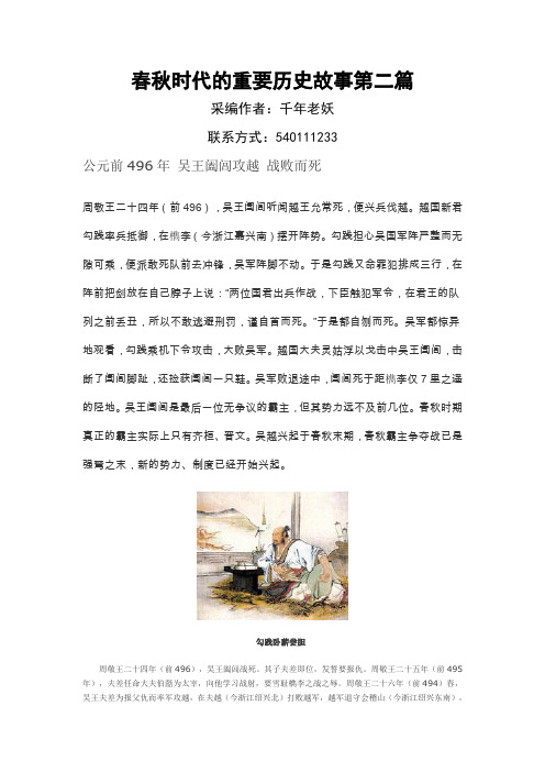
春秋时代的重要历史故事第二篇采编作者:千年老妖联系方式:540111233公元前496年吴王阖闾攻越战败而死周敬王二十四年(前496),吴王阖闾听闻越王允常死,便兴兵伐越。
越国新君勾践率兵抵御,在檇李(今浙江嘉兴南)摆开阵势。
勾践担心吴国军阵严整而无隙可乘,便派敢死队前去冲锋,吴军阵脚不动。
于是勾践又命罪犯排成三行,在阵前把剑放在自己脖子上说:“两位国君出兵作战,下臣触犯军令,在君王的队列之前丢丑,所以不敢逃避刑罚,谨自首而死。
”于是都自刎而死。
吴军都惊异地观看,勾践乘机下令攻击,大败吴军。
越国大夫灵姑浮以戈击中吴王阖闾,击断了阖闾脚趾,还捡获阖闾一只鞋。
吴军败退途中,阖闾死于距檇李仅7里之遥的陉地。
吴王阖闾是最后一位无争议的霸主,但其势力远不及前几位。
春秋时期真正的霸主实际上只有齐桓、晋文。
吴越兴起于春秋末期,春秋霸主争夺战已是强弩之末,新的势力、制度已经开始兴起。
勾践卧薪尝胆周敬王二十四年(前496),吴王阖闾战死。
其子夫差即位,发誓要报仇。
周敬王二十五年(前495年),夫差任命大夫伯嚭为太宰,向他学习战射,要雪耻檇李之战之辱。
周敬王二十六年(前494)春,吴王夫差为报父仇而率军攻越,在夫越(今浙江绍兴北)打败越军,越军退守会稽山(今浙江绍兴东南)。
越王勾践率披甲持盾的5000名士兵守卫,同时贿赂吴太宰伯嚭而求和。
越国又给夫差进献美女求和,伍员认为不妥,但夫差有志向北方扩土,不纳伍员之言,与越媾和。
勾践与范蠡作为人质留在吴国,卑事夫差,而把治理国政之事交给文种。
勾践在越三年,到周敬王二十九年(前491)吴王夫差赦勾践归国。
他苦心积虑,立志报仇雪恨,为了磨砺志气,不忘屈辱,他把苦胆挂在室内,吃饭之时一定要先尝苦胆。
睡觉时候身下垫着木柴,以使自己警惕,不得居安忘危,丧失报仇雪恨的决心。
他亲自与百姓一起共同耕作,让夫人织布裁衣,食不加肉,衣不饰采,与民同甘共苦。
经过长期的艰苦奋斗,“十年生聚,十年教训”,越国终于从失败中重新崛起。
百家姓

第十五章:280· 300
76. 281、池(chí ) 282、乔(qiáo) 283、阴(yīn) 284、郁(yù)
77.
78. 79. 80.
285、胥(xū)
289、闻(wén) 293、谭(tán) 297、姬(jī)
286、能(nài)
290、莘(shēn) 294、贡(gòng) 298、申(shēn)
287、苍(cāng)
291、党(dǎng) 295、劳(láo) 299、扶(fú)
288、双(shuāng)
292、翟(zhái) 296、逄(páng) 300、堵(dǔ)
第十六章:301· 320
81. 301、冉(rǎn) 302、宰(zǎi) 303、郦(lì ) 304、雍(yōng)
82.
83. 84. 85.
305、郤(xì )
309、濮(pú) 313、边(biān) 317、郏(jiá)
306、璩(qú)
310、牛(niú) 314、扈(hù) 318、浦(pǔ)
307、桑(sāng)
311、寿(shòu) 315、燕(yān) 319、尚(shàng)
308、桂(guì )
后增补到504个, 其中单姓444个, 复姓60个。
复姓。第二十一章:429· 448
01万俟(mò qí ) 05夏侯(xià hóu) 09赫连(hè lián) 02司马(sī mǎ) 06诸葛(zhū gě) 10皇甫(huáng pǔ) 03上官(shàng guān) 07闻人(wén rén) 11尉迟(yù chí ) 04欧阳(ōu yáng) 08东方(dōng fāng) 12公羊(gōng yáng)
涡流均匀性对柴油机燃烧影响的数值研究
/International Journal of Engine Research/content/13/5/482The online version of this article can be found at:DOI: 10.1177/14680874124378312012 13: 482 originally published online 8 May 2012International Journal of Engine Research Reza Rezaei, Stefan Pischinger, Jens Ewald and Philipp Adomeitcombustion and emissionsNumerical investigation of the effect of swirl flow in-homogeneity and stability on diesel enginePublished by: On behalf of:Institution of Mechanical Engineers can be found at:International Journal of Engine Research Additional services and information for/cgi/alerts Email Alerts:/subscriptions Subscriptions: /journalsReprints.nav Reprints:/journalsPermissions.nav Permissions:/content/13/5/482.refs.html Citations:What is This?- May 8, 2012OnlineFirst Version of Record- Sep 13, 2012Version of Record >>OriginalArticleInternational J of Engine Research13(5)482–496ÓRWTH Aachen University2012Reprints and permissions:/journalsPermissions.navDOI:10.1177/1468087412437831Numerical investigation of the effect ofswirl flow in-homogeneity and stabilityon diesel engine combustion andemissionsReza Rezaei1,Stefan Pischinger1,Jens Ewald2and Philipp Adomeit2AbstractThe present study is aimed at numerically investigating the effect of in-cylinder charge motion on mixture preparation, combustion and emission formation in a high-speed direct-injection diesel engine.Previous investigations have shown that different valve-lift strategies nominally lead to similar in-cylinder filling and global swirl levels.However,significant differences in engine-out emissions,especially soot emission,give rise to the assumption that the flow structure and local differences of the swirl motion distribution have a noticeable effect on emission behaviour.In this work,different swirl generation strategies applying different intake valve actuation schemes are numerically investigated by applying transient in-cylinder computational fluid dynamic simulations using both the Reynolds-averaged Navier–Stokes model and the multi-cycle large-eddy simulation approach.T wo operating points within the operating range of current diesel passenger cars during federal test procedure75and new European driving cycles are simulated.The injection and combustion simulations of different valve strategies show that an in-homogeneity in the in-cylinder flow structure leads to a signifi-cant increase in soot emissions,and agree with the observed trends of corresponding experimental investigations. KeywordsDiesel engine,simulation,in-cylinder flow,combustion,emission formationDate received:7October2010;accepted:11October2011IntroductionIn order to achieve new emission standards and reduce fuel consumption in future diesel engines,the combus-tion system requires intense development.In order to simultaneously improve the soot–nitrogen oxide(NO x) trade-off and decrease fuel consumption in comparison to traditional combustion systems,numerous advanced technologies are taken into consideration.These include high-pressure injection equipment using fast-opening piezo-actuated injectors on the one hand and,on the other hand,careful design of the piston bowl in order to reach an optimized distribution of the air–fuel mix-ture between bowl and squish volume.In addition to these,an optimization of the in-cylinder swirl charge motion is of vital importance.The effects of the in-cylinder charge motion distribution on combustion and emission behaviour of diesel engines are investigated in this study.The effects of in-cylinder flow and swirl in-homogeneity have been studied by several investiga-tors.In1995,Stephenson and Rutland1simulated intake flow and combustion in a heavy-duty direct-injection(DI)diesel engine resulting from different intake flow configurations and compared these with the significance of spray–wall interaction effects,using the computational fluid dynamic(CFD)code KIVA-3. Two separate computational grids were applied in KIVA:one for intake flow simulation and one for com-bustion simulation.At the time directly after intake valve closing(IVC),the data were mapped from the first grid to the combustion grid.Different valve-lift configurations with one and two active valves were simulated.Variations in the in-cylinder flow in terms of turbulent length scales and intensity,as well as their significance to combustion and emissions parameters, 1Institute for Combustion Engines,RWTH Aachen University,Germany 2FEV Motorentechnik GmbH,GermanyCorresponding author:R Rezaei,Institute for Combustion Engines,RWTH Aachen University, Schinkelstr.8,52062Aachen,Germany.Email:reza.rezaei@rwth.aachen.dewere compared with the significance of spray–wall interaction effects.It was concluded that at idling oper-ation,the differences in intake flow were considerably less important than at3/4load.Furthermore,it was found that valve deactivation led to higher turbulent kinetic energy and turbulent length scale.Bianchi et al.2investigated the influence of different initial flow conditions on combustion and emissions in a small-bore high-speed direct-injection(HSDI)diesel engine.The analysis was carried out by applying STAR-CD software for intake stroke simulation and KIVA-II for the compression stroke and combustion simulation.It was concluded that a detailed definition of the initial conditions is required to properly predict the mean and turbulent flow fields at the time of injec-tion near top dead centre(TDC),especially for small-bore HSDI diesel engines.The injection and combustion simulation using a full cylinder mesh was compared with simulation results considering a sector mesh simulation by Antila et al.3 In the case of an HSDI diesel engine,the difference between a sector mesh simulation and a full-cylinder mesh simulation was found to be considerable.The predicted injection velocity was found to have a note-worthy effect on the simulated heat release.3In2006,Adomeit et al.4showed that an eccentricity in the in-cylinder swirl flow pattern,observed by apply-ing the particle image velocimetry(PIV)measurement technique and intake stroke CFD analysis,can strongly affect the soot oxidation processes.Non-symmetric soot distribution was observed in laser-induced incan-descence(LII)measurements at the end of combustion due to an eccentric swirl flow before start of injection.In2008,Ge et al.5modelled the effect of the in-cylinder flow field on HSDI diesel engine performance and emissions.Two combustion models,KIVA-CHEMKIN and GAMUT(KIVA-CHEMKIN-G), coupled with a two-step and a multi-step phenomeno-logical soot model were applied.Numerical results were compared with experimental optical diagnostics obtained using laser-induced fluorescence(LIF),LII and PIV.It was concluded that the influence of the off-centred swirl flow on volume-averaged values,includ-ing in-cylinder pressure,temperature and heat release rate was negligible.The off-centred swirl flow was found to have higher turbulent kinetic energy and also higher turbulent viscosity.They have observed that an eccentric flow field detected in PIV measurements led to higher amounts of engine soot emissions.It should be noted that in Ge et al.5the intake stroke was not simulated and off-centred swirl flows with an assumed radial velocity distribution were initialized.Experimental investigations on gas exchange optimi-zation and its impact on emission reduction were pre-sented in previous work.6It was shown that increasing the swirl ratio up to a certain optimum level can improve the engine-out emissions and,simultaneously, the fuel consumption.Furthermore,it was observed that the optimum value of the swirl ratio depends on the operating conditions and engine speed.Therefore, in order to provide the corresponding flexibility,an HSDI diesel engine concept was developed that fea-tures a variable intake valve-lift system.In this previous work,the concept of numerically assessing the in-homogeneity of the in-cylinder swirl charge motion was introduced.Very-large-eddy simulation(VLES),a hybrid approach between large-eddy simulation(LES) and Reynolds-averaged Navier–Stokes(RANS)simu-lation of the in-cylinder flow fields for different valve-lift strategies of the same HSDI diesel engine were car-ried out and correlated to experimentally observed combustion performance.Multi-cycle simulations of the same operating point to cover cyclic instability and CFD simulations of combustion were not carried out at that stage of the research.In the present study,the work is extended to simu-late multi-cycle combustion.Both RANS modelling and the LES multi-cycle approach are employed for intake and compression flow simulations.Different swirl flow patterns are assessed and the numerically predicted emission behaviour,with regards to flow in-homogeneity,is compared to engine measurement results.MethodologyTest engineThe engine simulated in the present work is a state-of-the-art,small-size class,common-rail4V HSDI diesel engine with a dual intake port concept with seat swirl chamfers.6The piezo-actuated injector is located verti-cally at the centre of the fire deck and has a nozzle tip with eight evenly distributed holes.The engine specifi-cations are summarized in Table1.Detailed descrip-tions of the experimental setup can be found in Adolph et al.6The gas exchange process is optimized by using an intake port concept consisting of a filling and a tangen-tial port,both with seat swirl chamfers.6One important goal of this port concept is to provide a high volumetric efficiency by an optimized flow coefficient.Figure1 shows the flow measurements of the port design per-formed on a steady-state flow test bench.T able1.T est engine specification data.Bore(mm)75Stroke(mm)88.3Squish height(mm)0.7 Compression ratio15.1Fuel injection system Bosch2000barpiezo-actuated No.of nozzle hole8Nozzle hole diameter(m m)113Spray angle(°)153Intake valve opens(°CA ATDC)2355Engine control Bosch EDC16Rezaei et al.483At low valve lifts,an increase of the swirl ratio due to the effect of the swirl chamfers is visible.The use of the seat swirl chamfers on both intake valves ensures a higher swirl ratio and charge motion at low valve lifts. Using this port concept in combination with a variable intake-valve-lift system enables us to adapt the swirl ratio at each operating point.Four different maximum valve lifts from3.2mm to 8.0mm are investigated.The intake valve opening (IVO)and IVC times are kept constant while the maxi-mum valve lift is varied.The experimental results of two important operating points22801/min,9.4bar indicated mean effective pres-sure(IMEP)and15001/min,4.3bar IMEP6are intro-duced briefly in this section.These two operating points are selected for the numerical analysis because they are most frequently used in the new European driving cycle (NEDC)and federal test procedure(FTP)75cycles, and are therefore significant for the total engine-out emissions of these cycles.Start of injection is kept con-stant and exhaust gas recirculation(EGR)rate is var-ied.More discussion and comparison with CFD results will be given in the following sections.Figure2illustrates that the reduction of the intake valve lift from8.0mm to4.8mm significantly reduces smoke emission without any significant impact on fuel consumption for the15001/min operating point.A fur-ther reduction of the valve lift to3.2mm leads to an increase of gas exchange losses,and results in an increased fuel consumption without any improvement of the soot emissions.Another strategy to maintain an increased swirl ratio is the filling port deactivation in combination with a dual8.0–8.0mm valve lift(8.0mm port deactivation(PD)).In this case,both the soot emis-sions are deteriorated with a negative impact on fuel consumption compared to the4.8–4.8mm valve lift.The experimental investigations on the single-cylinder test engine for the operating point22801/min, 9.4bar IMEP are summarized in Figure3.It can be observed in the figure that reducing the maximum valve lift from8.0mm to4.8mm slightly improves the soot emissions.The8.0mm PD valve strategy produces a high amount of soot emissions similar to the8.0mm Figure2.Experimental observations of the effect of increasing the swirl ratio on emissions and fuel consumption,n=15001/min,IMEP=6.8bar.6Reprinted with permission from SAE paper2009-01-0653Ó2009SAE International.ISFC: indicated specific fuel consumption;FSN:fuel smokenumber. Figure3.Experimental observation of the effect of increasing the swirl ratio on emission and fuel consumption,n=22801/min, IMEP=9.4bar.6Reprinted with permission from SAE paper2009-01-0653Ó2009SAE International.FSN:fuel smoke number.Figure1.Stationary measured flow coefficient and swirl ratio.484International J of Engine Research13(5)dual valve lift.The reasons will be discussed in the next sections.Simulation procedure and numerical modelsIn this study,the KIVA-3V release2code,7with further developments by the Engine Research Center of Wisconsin University,8is used for injection and combus-tion simulation.Due to the availability of the source code,this is used for implementation of the one-equation LES approach.Additionally,the code is extended by further soot and NO x emission models.However,the capability of the code to fully resolve complex geometries is limited.Therefore,in this work,the software STAR-CD/ES-ICE is combined with the KIVA code in order to simulate in-cylinder charge motion generation,includ-ing the complete engine geometry.In-cylinder intake and compression simulation are carried out with the STAR-CD software.The simulated in-cylinder flow field is then mapped onto a mesh of the KIVA code shortly before start of injection.A schematic of the simulation chain is depicted in Figure4.For in-cylinder flow and combustion simulation, both the RANS model and the LES approach are applied.The renormalization group(RNG)k–e model8 is used in the KIVA code in the case of RANS simula-tion.Time averaging of the Navier–Stokes equations, commonly referred to as‘Reynolds averaging’greatly reduces the computational time,as it filters out the tran-sient spectrum of turbulence,which is modelled instead. Therefore,it is recognized that time-averaging models do not have the ability to capture cycle-to-cycle varia-tions in the flow field inside the combustion chamber accurately.More details about the RANS approach,its applications and limitations are given,for example,by Launder and Spalding9and Bardina et al.10The LES approach is a numerical technique to close the equations of turbulent flows by using spatial filter-ing.In the LES approach,larger turbulent structures (eddies)are directly calculated in a space-and time-accurate manner,while smaller eddies that are smaller than a filter length are modelled using sub-grid scale (SGS)models.By applying the LES approach,unsteady flow and engine cyclic variations can be resolved,while a RANS simulation averages out many cyclic phenomena.More details can be found,for example,in Sone et al.11In this study,the k-equation SGS model12is imple-mented into the KIVA-3V code.For brevity,the govern-ing equations and model formulation are not given here and can be found in Sone et al.,13with more details.The multi-cycle intake flow simulations in STAR-CD are carried out using the LES Smagorinsky model14 from IVO to30°crank angle(CA)after top dead centre (ATDC).Numerical simulation of injection,combus-tion and emission formation are subsequently carried out by the KIVA-LES code using the simulated in-cylinder flow field from STAR-CD.The applied spray atomization model accounts for combined Kelvin–Helmholtz and Rayleigh–Taylor dro-plet instabilities.8A phenomenological nozzle flow model15considering the nozzle passage inlet configura-tion is used.The commonly so-called‘Shell’five-species autoignition kinetic model16in combination with the characteristic-time combustion model8is used for igni-tion and combustion modelling.For modelling the soot emissions,the simple model of Hiroyasu and Kadota17and a well-validated multi-step soot model developed at the Institute for Combustion Engines at RWTH Aachen University18 are used.The phenomenological soot model is based on the eight-step soot formation of Kazakov and Foster19and a three-step oxidation model.20The gas sampling measurement as well as the LII and Raman laser diagnostic investigations were applied for local and time-dependent validation of the simu-lated gas temperature,as well as concentration of spe-cies like CO,O2and also the predicted soot emission inside the combustion chamber.18Furthermore,for the operating point1500l/min dis-cussed in the following,the applied combustion and soot models are evaluated by experimental results of ignition,flame propagation and local soot formation obtained from the LII and flame light emission measurement techniques,considering different valve strategies.21Figure4.The applied simulation strategy.Rezaei et al.485Boundary conditionsThe intake,compression and combustion simulations are carried out for following two operating points: engine speed 22801/min,9.4bar IMEP;engine speed 15001/min,6.8bar IMEP.Different valve strategies are simulated using both the RANS model and the LES approach for both operating points.For the case of 22801/min,the following two valve actuation strategies are simulated: dual opening with 4.8–4.8mm maximum valve lift (4.8–4.8mm);dual opening with 8.0–8.0mm maximum valve lift,but with port deactivation by closing the filling port (8.0mm PD).For each of the above valve actuation strategies 10cycles are simulated using the LES approach.The boundary conditions,such as wall temperatures,are kept the same for each valve strategy during the multi-cycle simulations.Figure 5shows the measured intake pressure curves and its standard deviation of 10cycles with 4.8–4.8mm maximum valve lift,which are directly applied as boundary conditions to the CFD simulations.There are very small perturbations in the measured intake pressure boundary conditions.These perturbationsfinally cause stochastic variations in the in-cylinder flow structures on the microscopic and intermediate length and time scales.The result are cycle-to-cycle variations,for example,in terms of the flow in-homogeneity.In the LES approach,such small perturbations and fluc-tuations in flow turbulence are not filtered out as in the RANS model.Furthermore,previous work 6showed that flow structures predicted by LES approaches exhi-bit much stronger differences between different valve actuations strategies than RANS.This makes the LES an appropriate model for simulation and analysis of transient phenomena like engine cycle-to-cycle variability.The second operating point investigated in this work is 15001/min with 6.8bar IMEP.Three valve strategies 8.0–8.0mm,8.0mm PD and 4.8–4.8mm are selected for the numerical investigations applying the RANS and the LES approach.For brevity,only the cycle-averaged intake pressure curves of the three valve stra-tegies are depicted in Figure 6.Computational meshIn this study,a complete mesh consisting of intake and exhaust ports,seat swirl chamfers,piston and a cylinder head for different valve strategies is generated by the ES-ICE software and applied in STAR-CD for intake and compression flow simulation.As depicted in Figure 7(a),the grid used for intake and compression simula-tion extends exactly to the intake pressure sensor loca-tion in order to use the measured intake pressure as boundary conditions of the simulation.A good level of mesh resolution is essential for accu-rate turbulence modelling employing the LES approach.The quality of the computational grid used is evaluated with two different methods,21which are not given here for brevity.For the a priori analysis,the size of the large energy containing eddies obtained by the RANS model is compared with the grid size in the intake ports and the combustion chamber.21It is shown by Rezaei 21that the mesh resolution during the intake phase at some local positions,like near valveregions,Figure 5.Measured and standard deviation of intake pressure boundary condition,4.8–4.8mm,n=22801/min,IMEP=9.4bar.ABDC:after bottom dead centre.Figure 6.Averaged intake pressure boundary condition of all simulated valve strategies,multi-cycle,n=15001/min,IMEP=6.8bar.486International J of Engine Research 13(5)must be improved.As a further evaluation,it is shownthat the amount of the turbulent kinetic energy directly resolved by the LES approach is about 85–90%of the total turbulent kinetic energy in the intake and com-pression phase.21Figure 7(b)illustrates the side and top view of the mesh used in KIVA at the mapping point 230°CA ATDC.A summary of the number of computational cells used in each mesh type is given in Table 2.ResultsTraditionally,charge motion in diesel engines is described by the swirl ratio,which is a global measure obtained by integration of the swirl momentum in the entire combustion chamber.Recent experimental and numerical investigations have shown that in-homogeneity and local differences in the in-cylinder flow structure have noticeable impacts on combustion and emissions.In the following sections,the effects of different flow structures generated by different swirl generation strategies on combustion and hence emis-sion behaviour are described.Evaluation of in-cylinder flow and swirl qualityThe intake pressure is adjusted at the test bench in order to reach the same in-cylinder filling for both cases.For evaluation and assessment of the in-cylinder flow field in HSDI diesel engines,Adolph et al.6introduced the homogeneity of the swirl flow as an additional criterion for quantitative assessment of swirl flow pattern and its homogeneity.Here,we will employ the definition of flow in-homogeneity as proposed in Adolph et al.6The in-homogeneity,I in-hom ,is defined as the root mean square of the tangential in-cylinder flow velocity at each cross-section normalized by the absolute value of the flow-velocity component in the same tangential direc-tion,averaged in the complete in-cylinder volume,I in Àhom =P N sectionsection =1RMS V u ,section A sectionP N sectionsection =1V u ,section A sectionð1Þwhere A section is the area of the considered cross-section,V u ,sec tion and RMS V u ,sec tion are the mean and root mean square of the tangential velocity at the considered cross-section,respectively.In other words,it is a measure of deviation of the in-cylinder swirl from a rigid-body rotation such that for a more in-homogeneous flow field,higher values of the in-homogeneity index are calculated.As already shown in Adolph et al.6(see also Figure 8),applyingFigure 8.In-homogeneity index calculated for the complete combustion chamber,n=22801/min,IMEP=9.4bar:(a)RANS results and (b)LES results.IntakeExhaustSwirl chamferTangentialportIntake pressureFilling port(Closed in case of port deactivation)Figure putation meshes applied in this study.(a)Full geometry mesh used for intake and compression simulation by STAR-CD.(b)Full cylinder mesh applied in the KIVA code for injection and combustion simulation.T able 2.Mesh types and number of computational cells.Mesh type Number of cells STAR-CD 935,000KIVA450,000Rezaei et al.487the RANS and LES models,the variant4.8–4.8mm and the8.0mm PD valve strategies nominally lead to similar global swirl levels,but because of different flow structures,the calculated in-homogeneity indexes are different.The in-homogeneity index for the4.8–4.8mm valve strategy is lower than for8.0mm PD.For brev-ity,only the operating point22801/min is considered.As depicted in Figure8,due to the capability of the LES approach in capturing the unsteady flow and tran-sient phenomena that are not averaged out,as in the RANS model,the cycle-to-cycle variations in the in-cylinder flow homogeneity can be observed.The role of cyclic variation of in-cylinder flow field on combustion and emission behaviour is not discussed here for brev-ity,but is given in Rezaei21with more details,including the experimental investigations.The velocity magnitude at the cross-sectional view at the middle of the bowl,for two operating points 22801/min and15001/min simulated by the RANS model as well as ensemble average results of the LES multi-cycle approach,are plotted in Figure9.As is qualitatively illustrated in Figure9,the velocity distri-bution in a circumferential section shortly before start of injection for the variant8.0mm PD is more in-homogeneous.The effect of in-cylinder flow on combustionand emissionsIn-cylinder swirl flow motion can enhance mixing pro-cesses,may lead to a more homogeneous mixture and,consequently,can improve emission formation. Increasing the swirl ratio(until an optimal value is achieved);for example,by means of combining the seat swirl chamfer and a reduction of the valve lift,leads to a better air–fuel mixing and mixture preparation,which decreases pollutant emissions.Another effect that is studied here in more detail is the in-homogeneity of the swirl flow pattern,which affects the distribution of mixture during the combustion process and hence the emission formation.Numerical investigations of in-cylinder flow show that the variant8.0mm PD has a higher flow in-homogeneity than4.8–4.8mm.A noticeable increase in the soot emissions was observed when comparing both valve strategies at the test bench.6The results of numer-ical investigations of combustion and emission forma-tion are presented in the following sections.RANS modelling.Numerical simulations of injection, combustion and emission formation are carried out using a modified version of KIVA-3V release2.7The two operating points given above are investigated.22801/min,9.4bar IMEP.In order to study only the effect of the in-cylinder flow and to isolate other effects, all other operating conditions,in-cylinder mass,air–fuel ratio,injection system,and so on,are kept the same for both valve strategies,4.8–4.8mm and8.0mm PD in the numerical and experimental investigations. The intake pressure was adjusted at the test bench to get the same in-cylinder air mass for both cases.The measured intake pressures are directly used in the CFD simulations.For the8.0mm PD case,both intake valves have8.0mm maximum lift and the filling port is closed.The operating conditions are summarized in Table3.According to the measured EGR ratio,com-position of the intake air is calculated.Figure10compares the simulated pressure curves and the heat release rate of the operating point22801/ min,9.4bar IMEP employing both the4.8–4.8mm and 8.0mm PD valve strategies with the measurements car-ried out on the single-cylinder test engine.Good agree-ment is found between measured and simulated KIVA results.Figure9.Cross-sectional view of the velocity magnitude at the middle of the bowl:(a)RANS results and(b)ensemble average LES results,n=2280and15001/min.T able3.Engine operating conditions,22801/min,9.4bar IMEP. Engine speed(1/min)2280 Lambda 2.22 EGR rate31% IMEP(bar)9.4 Injected mass(mg)19.6 Rail pressure(bar)970 Start of pilot injection(°CA ATDC)222.5 Start of main injection(°CA ATDC)20.2488International J of Engine Research13(5)The calculated in-cylinder emissions for both valve strategies are plotted in Figure 11.The transient curves of the soot concentration show first of all that the sim-ple one-step soot model of Hiroyasu and Kadota 17fails to detect the observed trend of soot increase between the cases at the end of the exhaust stroke.In contrast,the phenomenological multi-step 18soot mechanism exhibits the difference between the two valve-lift strate-gies from approximately 16°CA ATDC.Furthermore,with this model,it is seen that before that crank angle position the soot concentration for the 4.8–4.8mm valve strategy is predicted to be higher,but thereafter,the oxidation rate of soot is stronger for this strategy.Another possibility to analyse the differences in mix-ture formation is the comparison in terms of airutilization.Air utilization is defined here as the volume fraction of mixture with a relative air–fuel ratio l between 0.0and 2.0.For the 4.8–4.8mm case,higher values of air utilization are calculated.On the other hand,there are only marginal differences in the CO and NO x emissions between both valve strategies.In order to compare the simulated trend in the soot emissions with the observed trend on the test bench,both experimental and numerical investigations are now normalized to the corresponding 4.8–4.8mm valve strategy.Figure 12illustrates the trend of increased soot emissions by applying 8.0mm PD instead of 4.8–4.8mm valve lift,for both CFD predictions and mea-surements of the operating point 22801/min and 9.4bar IMEP.Both analyses show a significant increase in the same direction for soot emissions between the two dif-ferent valve-lift strategies.In order to analyse the mixture formation in a more detailed way,the air utilization is given in Figure 13,considering four different ranges in air–fuel ratio.The difference between the two additional curves shows the volume fraction of the mixture with a lambdavalueFigure 10.Heat release analysis of the CFD simulation using the RANS model in comparison with the engine measurement data at n=22801/min,IMEP=9.4bar.Figure 11.Calculated air utilization and emissions using the RANS model,n=22801/min,IMEP=9.4bar.Rezaei et al.489。
2020年一级消防工程师《技术实务》新旧教材变化对比
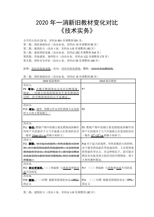
2020年一消新旧教材变化对比《技术实务》全书共计改动25处,页码由654页调整到854页。
第一篇:消防基础知识(改动6处,页码由45页调整到58页)第二篇:建筑防火(改动4处,页码由148页调整到192页)第三篇:建筑消防设施(改动6处,页码由252页调整到316页)第四篇:其他建筑、场所防火(改动8处,页码由122页调整到173页)第五篇:消防安全评估(改动1处,页码由83页调整到106页)新增:对应内容加双线;改动:对应内容加虚线;删除:对应内容加删除线。
第一篇:消防基础知识(改动6处,页码由45页调整到58页)2020版新教材2019版旧教材改动1:P9增加:少数可燃固体也会存在闪燃现象,例如,一些熔点较低的固体发生蒸发燃烧的过程,但可燃固体的闪点不易测定。
P7改动2:P10增加:通常,用燃点作未评价固体火灾危险性大小的主要依据之一P8改动3:P11修改:燃烧产物中的烟主要是燃烧或热解作用所产生的悬浮于大气中能被人们看到的直径一般在10nm-10μm的极小炭粒子;P8燃烧产物中的烟主要是燃烧或热解作用所产生的悬浮于大气中能被人们看到的直径一般在10-7-10-4cm的极小炭粒子;改动4:P21删除:对于起火的场所,导热系数的大的材料,由于能受到高温作用迅速加热,又会很快地把热能传导出去,在这种情况下,就可能引燃没有直接受到火焰作用的可燃物质,利于火势传播和蔓延。
P16对于起火的场所,导热系数的大的材料,由于能受到高温作用迅速加热,又会很快地把热能传导出去,在这种情况下,就可能引燃没有直接受到火焰作用的可燃物质,利于火势传播和蔓延。
改动5:P22表达更规范:(三)热辐射与热传导和热对流不同的是P17(三)热辐射与导热和对流不同的是改动6:P29删除:(二)回燃根据美国消防协会(NFPA)的定义P22(二)回燃根据美国消防协会(NFPA)的定义第二篇:建筑防火(改动4处,页码由148页调整到192页)2020版新教材2019版旧教材改动1:P89增加:建筑材料按平板状建筑材料、铺地材料、管状绝热材料三类,分别用不同的试验方法确定了相应的分级判据。
- 1、下载文档前请自行甄别文档内容的完整性,平台不提供额外的编辑、内容补充、找答案等附加服务。
- 2、"仅部分预览"的文档,不可在线预览部分如存在完整性等问题,可反馈申请退款(可完整预览的文档不适用该条件!)。
- 3、如文档侵犯您的权益,请联系客服反馈,我们会尽快为您处理(人工客服工作时间:9:00-18:30)。
(5)贮存装置安装,定额中包括灭火剂贮存容器和驱动气瓶的安装固定支框架、系统组件(集流管,容器阀,气液单向阀, 高压软管),安全阀等贮存装置和阀驱动装置的安装及氮气增压。二氧化碳贮存装置安装时,不须增压,执行定额时,扣除 高纯氮气,其余不变。
(6)二氧化碳称重检漏装置包括泄漏报警开关、配重及支架。 (7)系统组件包括选择阀,气液单向阀和高压软管。 (8)本章定额不包括的工作内容: 1)管道支吊架的制作安装应执行本册定额第二章的相应项目。 2)不锈钢管、铜管及管件的焊接或法兰连接,各种套管的制作安装。管道系统强度试验、严密性试验和吹扫等均执行第 六册《工业管道工程》定额相应项目。 3)管道及支吊架的防腐刷油等执行第十一册《刷油、防腐蚀、绝热工程》定额相应项目。 4)系统调试执行本册定额第五章的相应项目。 5)阀驱动装置与泄漏报警开关的电气接线等执行第十册《自动化控制仪表安装工程》。 4.泡沫灭火系统安装说明: (1)本章定额适用于高、中、低倍数固定式或半固定式泡沫灭火系统的发生器及泡沫比例混合器安装。 (2)泡沫发生器及泡沫比例混合器安装中包括整体安装、焊法兰、单体调试及配合管道试压时隔离本体所消耗的人工和材 料。但不包括支架的制作、安装和二次灌浆的工作内容。地脚螺栓按本体带有考虑。 (3)本章不包括的内容: 1)泡沫灭火系统的管道、管件、法兰、阀门、管道支架等的安装及管道系统水冲洗、强度试验、严密性试验等执行第六 册《工业管道工程》相应定额。 2)泡沫喷淋系统的管道、组件、气压水罐、管道支吊架等安装可执行本册第二章相应定额及有关规定。 3)消防泵等机械设备安装及二次灌浆执行第一册《机械设备安装工程》相应项目。 4)泡沫液贮罐、设备支架制作安装执行第五册《静置设备与工艺金属结构制作安装工程》相应项目。
火焰探测器、可燃气体探测器接线制的不同分为多线制与总线制两种,计算时不分规格、型号,安装方式与位置,以“只” 为计量单位。探测器安装包括了探头和底座的安装及本体调试。
线形探测器的安装方式接环绕、正弦及直线综合考虑,不分线制及保护形式,以“m”为计量单位。定额中未包括探测器连 接的一只模块和终端,其工程量应按相应额另行计算。
2、阀门、法兰安装,各种套管的制作与安装,不锈钢管和管件,铜管和管件及泵间管道安装,管道系统强度试验、严密性 试验和管道冲洗等执行第六册《工业管工程》相应定额项目。
3、消火栓管道、室外给水管道安装及水箱制作与安装执行第八册《给排水、采暖、燃气工程》相应定额项目。 4、各种消防泵、稳压泵等机械设备安装及二次灌浆执行第一册《机械设备安装工程》相应定额项目。 5、各种仪表的安装及带电信号的阀门、水流指示器、压力开关、驱动装置及泄漏报警开关的接线、校线等执行第十册《自 动化控制仪表安装工程》相应定额项目。 6、泡沫液储罐、设备支架制作与安装等执行第五册《静置设备与工艺金属结构制作安装工程》相应定额项目。 7、设备及管道除锈、油漆及绝热工程执行第十一册《刷油、防腐蚀、绝热工程》项目。
二、计价表中用系数计算的费用:
l、脚手架搭拆费 脚手架搭拆费,按人工费的5%计算,其中人工工资占25%。 2、安装与生产同时进行增加费 安装与生产同时进行增加的费用,按人工费的l0%计算。 3、在有害身体健康环境中施工增加费 在有害身体健康环境中施工增加的费用,按人工费的10%计算。
4、高层建筑增加费 高层建筑增加费(指高度在6层或20m以上的工业与民用建筑)按下表计算(其中部为人工工资)。
第四章 消防工程工程量清单计价
第一节 消防工程计价表的概述
《江苏省安装工程计价表》第七册,主要内容如下表:
《消防及安全防范设备》的分部分项工程名称表
一、与有关定额册的关系
本册定额适用于工业与民用建筑中的新建、扩建和整体更新改造工程中消防及安全防范设备的安装。未列入的项目,可使 用有关计价表项目:
1、电缆敷设、桥架安装、配管配线、接线盒、动力、应急照明控制设备、应急照明器具动机检查接线、防雷接地装置等安 装,均执行第二册《电气设备安装工程》相应定额项目。
(11)本章不包括以下工作内容: 1)阀门、法兰安装,各种套管的制作安装,泵房间管道安装及管道系统强度试验、严密性试验。 2)消火栓管道、室外给水管道安装及水箱制作安装。 3)各种消防泵、稳压泵安装及设备二次灌浆等。 4)各种仪表的安装及带电讯号的阀门、水流指示器、压力开关的接线、校线。 5)各种设备支架的制作安装。 6)管道、设备、支架、法兰焊口除锈刷油。 7)系统调试。 3、气体灭火系统安装说明: (1)本章定额适用于工业和民用建筑中设置的二氧化碳灭火系统、卤代烷1211灭火系统和卤代烷1301灭火系统中的管道、管 件、系统组件等的安装; (2)本章定额中的无缝钢管、钢制管件、选择阀安装及系统组件试验等均适用于卤代烷1211和1301灭火系统,二氧化碳灭火 系统按卤代烷灭火系统相应定额乘以系数1.20。 (3)管道及管件安装定额: 1)无缝钢管和钢制管件内外镀锌及场外运输费用另行计算。 2)螺纹连接的不锈钢管、铜管及管件安装时,按无缝钢管和钢制管件安装相应定额乘以系数1.20。 3)无缝钢管螺纹连接定额中不包括钢制管件连接内容,应设计用量执行钢制管件连接定额。 4)无缝钢管法兰连接定额,管件是按成品、弯头两端是按接短管焊接法兰考虑的,定额中包括了直管、管件、法兰等全部 安装工序内容,但管件、法兰及螺栓的主材数量应按设计规定另行计算。 5)气动驱动装置管道安装定额中卡套连接件的数量按设计用量另行计算。 (4)喷头安装定额中包括管件安装及配合水压试验安装拆除丝堵的工作内容。
9、超高增加费:指操作物高度距离楼地面5m以上的工程,按其超过部分的定额人工费乘以下列系数:
三、计价表的章节说明
1、火灾自动报警系统安装说明: (1)本章包括探测器、按钮、模块(接口)、报警控制器、联动控制器、报警联动一体动、重复显示器、警报装置、远程 控制器、火灾事故广播、消防通讯、报警备用电源安装等项目。 (2)本章包括以下工作内容: 1)施工技术准备、施工机械准备、标准仪器准备、施工安全防护措施、安装位置的清理。 2)设备和箱、机及元件的搬运、开箱检查,清点,杂物回收,安装就位,接地,密封,箱、机内的校线、接线,挂锡、编 码、测试、清洗、记录整理等。 (3)本章定额中均包括了校线、接线和本体调试。 (4)本章定额中箱、机是以成套装置编制的;柜式及琴台式安装均执行落地式安装相应项目。 (5)本章不包括以下工作内容: 1)设备支架、底座、基础的制作与安装。 2)构件加工制作。 3)电机检查、接线及调试。 4)事故照明及疏散指示控制装置安装。 5)CRT彩色显示装置安装。
按钮包括消火栓按钮、手动报警按钮、气体灭火起/停按钮,以“只”为计量单位,按照在轻质墙体和硬质墙体上安装两 种方式综合考虑,执行时不得因安装方式不同而调整。
控制模块(接口)是指仅能起控制作用的模块(接口),亦称为中继器,依据其给出控制信号的数量,分为单输出和多输 出两钟形式。执行时不分安装方式,按照输出数量以“只”为计量单位。
第二节 计价表工程量计算规则
一、火灾自动报警系统
点型探测器按线制的不同分为多线制与总线制,不分规格、型号、安装方式与位置,以பைடு நூலகம்只”为计量单位。探测器安装包 括了探头和底座的安装及本体调试。
红外线探测器以“只”为计量单位。红外线探测器是成对使用的,在计算时一对为两只。定额中包括了探头支架安装和探 测器的调试、对中。
报警模块(接口)不起控制作用,只能起监视、报警作用,执行时不分安装方式,以“只”为计量单位。 报警控制器接线制的不同分为多线制与总线制两种,其中又按其安装方式不同分为壁挂式和落地式。在不同线制、不同安 装方式中按照“点”数的不同划分定额项目,以“只”为计量单位。 多线制“点”是指报警控制器所带报警器件(探测器、报警按钮等)的数量。 总线制“点”是指报警控制器所带的有地址编码的报警器件(探测器、报警按钮、模块等的数量。如果一个模块带数个探 测器,则只能计为一点。 联动控制器接线制的不同分为多线制与总线制两种,其中又按其安装方式不同分为壁挂式和落地式。在不同线制、不同安 装方式中按照“点”数的不同划分定额项目,以“台”为计量单位。
5、设置于管道间和管廊内的管道安装系数 设置于管道间、管廊内的管道安装,其定额人工乘以系数1.30。 6、主体结构为现场浇注采用钢模施工的工程系数 主体结构为现场浇注采用钢模施工的工程:内外浇注的定额人工乘以系数1.05,内浇外砌的定额人工乘以系数1.03。 7、螺纹连接的不锈钢管和铜管及管件安装时的系数 螺20连接的不锈钢管、铜管及管件安装时,按无缝钢管和钢制管件安装相应定额,乘以系数1.20。 8、黑白、彩色摄像机折算系数规定 在执行电视监控设备安装定额时,其综合工日应根据系统中摄像机台数和距离(摄像机与控制器之间电缆实际长)远近的 系数规定,分别按下表乘以折算系数。
2、水灭火系统安装说明: (1)本章定额适用于工业和民用建(构)筑物设置的自动喷水灭火系统的管道、各种组件、消火栓、气压水罐的安装及管道 支吊架的制作、安装。 (2)界线划分: 1)室内外界线:以建筑物外墙皮1.5m为界,入口处设阀门者以阀门为界。 2)设在高层建筑内的消防泵间管道与本章界线,以泵间外墙皮为界。 (3)管道安装定额: 1)包括工序内一次性水压试验。 2)镀锌钢管法兰连接定额,管件是按成品、弯头两端是按接短管焊法兰考虑的,定额中包括了直管、管件、法兰等全部安装 工序内容,但管件、法兰及螺栓的主材数量应按设计规定另行计算。 3)定额也适用于镀锌无缝钢管的安装。 (4)喷头、报警装置及水流指示器安装定额均按管网系统试压、冲洗合格后安装考虑的,定额中已包括丝堵、临时短管的安 装、拆除及其摊销。 (5)其他报警装置适用于雨淋、干湿两用及预作用报警装置。 (6)温感式水幕装置安装定额中已包括给水三通至喷头、阀门间的管道、管件、阀门、喷头等全部安装内容。但管道的主材 数量按设计管道中心长度另加损耗计算;喷头数量按设计数量另加损耗计算。 (7)集热板的安装位置:当高架仓库分层板上方有孔洞、缝隙时,应在喷头上方设置集热板。 (8)隔膜式气压水罐安装定额中地脚螺栓是按设备带有考虑的,定额中包括指导二次灌浆用工,但二次灌浆费用另计。 (9)管道支吊架制作安装定额中包括了支架、吊架及防晃支架。 (10)管网冲洗定额是按水冲洗考虑的,若采用水压气动冲洗法时,可按施工方案另行计算。定额只适用于自动喷水灭火系统。
