HFR125中文资料
40HFR10资料
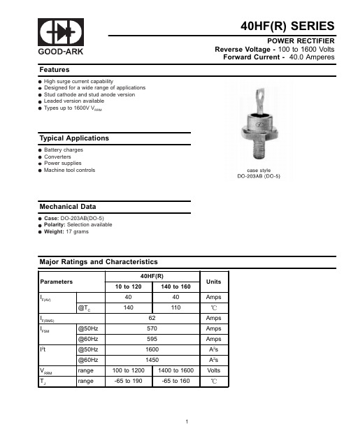
Major Ratings and Characteristics
Parameters 40HF(R) 10 to 120 140 to 160 Units
IF(AV) @TC IF(RMS) IFSM It
2
40 140 62 @50Hz @60Hz @50Hz @60Hz range range 100 to 1200 -65 to 190 570 595 1600 1450
Tstg Max. storage temperature range RthJC Max. thermal resistance, junction to case RthCS Max. thermal resistance, cБайду номын сангаасse to heatsink T Max. allowed mounting torque 10%
(1)
IRRM max. @TJ=TJ max. mA 15
(1) Avalanche version only available from V RRM 400V to 1600V.
Forward Conduction
Parameter IF(AV) IF(RMS) IFSM Max. average forward current @ Case temperature Max. RMS forward current Max. peak, one-cycle forward, non-repetitive surge current 40HF(R) 10 to 120 40 140 62 570 595 480 500 I2t Maximum I2t for fusing 1600 1450 1150 1050 VFM Max. forward voltage drop 1.30 Volts A2S Amps 140 to 160 40 110 Amps t=10ms t=8.3ms t=10ms t=8.3ms t=10ms t=8.3s t=10ms t=8.3ms No voltage reapplied 100% VRRM reapplied No voltage reapplied 100% VRRM reapplied , tp=400us rectangular wave Units Amps Conditions
TAE125发动机培训资料_综述
TAE125发动机培训资料_综述目录1 柴油发动机 ................................................ ................................................... (2)功能 ................................................ ................................................... ............................ 2 共轨喷嘴 ................................................ ................................................... ..................... 3 2 TAE 125系列航发 ................................................ ................................................... .. (3)关于引擎 ................................................ ................................................... ..................... 3 燃油系统 ................................................................................................... ..................... 5 润滑 ................................................ ................................................... ............................ 7 冷却系统 ................................................ ................................................... ..................... 7 (感应)系统和涡轮增压 ................................................ ................................................... .. 8 螺旋桨控制系统 ................................................ ................................................... ........... 9 电子系统 ................................................ ................................................... ....................10 性能 ................................................ ................................................... ...........................10 系统 ................................................ ................................................... (11)功能 ................................................ ................................................... ...........................11 的冗余设计和故障诊断 ................................................ ......................................13 4.结论 ................................................ ................................................... (18)总览TMG 是大陆发动机集团的分支机构,中航国际旗下的公司。
LF, HF, UHF都分别代表什么

LF, HF, UHF都分别代表什么和我们听的收音机道理一样,射频标签和阅读器也要调制到相同的频率才能工作。
LF,HF,UHF 就对应着不同频率的射频。
LF代表低频射频,在125KHz左右,HF代表高频射频,在左右,UHF代表超高频射频,在860至960MHz范围之内。
对一个RFID系统来说,它的频段概念是指读写器通过天线发送、接收并识读的标签信号频率范围。
从应用概念来说,射频标签的工作频率也就是射频识别系统的工作频率,直接决定系统应用的各方面特性。
在RFID系统中,系统工作就像我们平时收听调频广播一样,射频标签和读写器也要调制到相同的频率才能工作。
射频标签的工作频率不仅决定着射频识别系统工作原理(电感耦合还是电磁耦合)、识别距离,还决定着射频标签及读写器实现的难易程度和设备成本。
RFID应用占据的频段或频点在国际上有公认的划分,即位于ISM波段。
典型的工作频率有:125kHz、133kHz、、、433MHz、902MHz~928MHz、、等。
按照工作频率的不同,RFID标签可以分为低频(LF)、高频(HF)、超高频(UHF)和微波等不同种类。
不同频段的RFID工作原理不同,LF和HF频段RFID电子标签一般采用电磁耦合原理,而UHF及微波频段的RFID一般采用电磁发射原理。
目前国际上广泛采用的频率分布于4种波段,低频(125KHz)、高频()、超高频(850MHz~910MFz)和微波()。
每一种频率都有它的特点,被用在不同的领域,因此要正确使用就要先选择合适的频率。
低频段射频标签,简称为低频标签,其工作频率范围为30kHz~300kHz。
典型工作频率有125KHz 和133KHz。
低频标签一般为无源标签,其工作能量通过电感耦合方式从阅读器耦合线圈的辐射近场中获得。
低频标签与阅读器之间传送数据时,低频标签需位于阅读器天线辐射的近场区内。
低频标签的阅读距离一般情况下小于1米。
低频标签的典型应用有:动物识别、容器识别、工具识别、电子闭锁防盗(带有内置应答器的汽车钥匙)等。
85HFR20M资料

Document Number: 93529For technical questions, contact: ind-modules@Standard Recovery Diodes,(Stud Version), 85 A85HF(R) SeriesVishay High Power ProductsFEATURES•High surge current capability •Stud cathode and stud anode version •Leaded version available •Types up to 1600 V V RRM •RoHS compliant•Designed and qualified for industrial levelTYPICAL APPLICATIONS•Battery chargers •Converters •Power supplies•Machine tool controls •WeldingELECTRICAL SPECIFICATIONS PRODUCT SUMMARYI F(AV)85 ADO-203AB (DO-5)MAJOR RATINGS AND CHARACTERISTICSPARAMETER TEST CONDITIONS85HF(R)UNITS 10 TO 120140/160I F(AV)85A T C140110°C I F(RMS)133A I FSM 50 Hz 1700A 60 Hz 1800I 2t 50 Hz 14 500A 2s 60 Hz 13 500V RRM Range100 to 12001400/1600V T J- 65 to 180- 65 to 150°CVOLTAGE RATINGSTYPE NUMBERVOLTAGE CODEV RRM , MAXIMUM REPETITIVE PEAK REVERSE VOLTAGEVV RSM , MAXIMUM NON-REPETITIVEPEAK REVERSE VOLTAGEVI RRM MAXIMUM AT T J = T J MAXIMUMmA85HF(R)10100200920200300404005006060070080800900100100011001201200130014014001500 4.516016001700元器件交易网 For technical questions, contact: ind-modules@Document Number: 9352985HF(R) SeriesVishay High Power Products Standard Recovery Diodes,(Stud Version), 85 ANotes(1)Available only for 88HFFORWARD CONDUCTIONPARAMETERSYMBOL TEST CONDITIONS85HF(R)UNITS 10 to 120140/160Maximum average forward current at case temperatureI F(AV)180° conduction, half sine wave85A 140110°C Maximum RMS forward currentI F(RMS)133AMaximum peak, one-cycle forward, non-repetitive surge currentI FSMt = 10 msNo voltage reapplied Sinusoidal half wave,initial T J = T J maximum1700At = 8.3 ms 1800t = 10 ms 100 % V RRM reapplied 1450t = 8.3 ms 1500Maximum I 2t for fusingI 2tt = 10 msNo voltage reapplied 14 500A 2s t = 8.3 ms 13 500t = 10 ms 100 % V RRM reapplied10 500t = 8.3 ms9400Maximum I 2√t for fusing I 2√tt = 0.1 to 10 ms, no voltage reapplied16 000A 2√s Value of threshold voltage (up to 1200 V)V F(TO)T J = T J maximum0.68V Value of threshold voltage (for 1400 V, 1600 V)0.69Value of forward slope resistance (up to 1200 V)r fT J = T J maximum1.62m ΩValue of forward slope resistance (for 1400 V, 1600 V)1.75Maximum forward voltage dropV FMI pk = 267 A, T J = 25 °C, t p = 400 µs rectangular wave1.21.4V THERMAL AND MECHANICAL SPECIFICATIONSPARAMETERSYMBOL TEST CONDITIONS85HF(R)UNITS 10 to 120140/160Maximum junction operating and storage temperature range T J , T Stg - 65 to 180- 65 to 150°CMaximum thermal resistance,junction to caseR thJC DC operation0.35K/WMaximum thermal resistance,case to heatsink R thCSMounting surface, smooth, flat and greased0.25Maximum shock (1)1500gMaximum constant vibration (1)50 Hz 20Maximum constant acceleration (1)Stud outwards 5000Allowable mounting torqueNot lubricated threads3.4 + 0 - 10 %(30)N · m (lbf · in)Lubricated threads2.3 + 0 - 10 %(20)Approximate weight Unleaded device17g 0.6oz.Case style See dimensions - link at the end of datasheetDO-203AB (DO-5)元器件交易网Document Number: 93529For technical questions, contact: ind-modules@85HF(R) SeriesStandard Recovery Diodes,(Stud Version), 85 AVishay High Power ProductsNote•The table above shows the increment of thermal resistance R thJC when devices operate at different conduction angles than DCFig. 1 - Current Ratings Characteristics Fig. 2 - Current Ratings Characteristics Fig. 3 - Current Ratings CharacteristicsFig. 4 - Current Ratings CharacteristicsΔR thJC CONDUCTIONCONDUCTION ANGLESINUSOIDAL CONDUCTIONRECTANGULAR CONDUCTIONTEST CONDITIONSUNITS180°0.100.08T J = T J maximumK/W120°0.110.1190°0.130.1360°0.170.1730°0.260.26元器件交易网For technical questions, contact: ind-modules@Document Number: 9352985HF(R) SeriesVishay High Power Products Standard Recovery Diodes,(Stud Version), 85 AFig. 5 - Forward Power Loss CharacteristicsFig. 6 - Forward Power Loss CharacteristicsFig. 7 - Forward Power Loss Characteristics元器件交易网85HF(R) Series Standard Recovery Diodes,(Stud Version), 85 AVishay High Power Products Fig. 8 - Forward Power Loss CharacteristicsFig. 9 - Maximum Non-Repetitive Surge Current Fig. 10 - Maximum Non-Repetitive Surge Current Fig. 11 - Forward Voltage Drop Characteristics(up to 1200 V)Fig. 12 - Forward Voltage Drop Characteristics(for 1400 V, 1600 V)元器件交易网Document Number: 93529For technical questions, contact: ind-modules@ 元器件交易网Vishay High Power Products Standard Recovery Diodes,(Stud Version), 85 A ArrayFig. 13 - Thermal Impedance Z thJC CharacteristicsORDERING INFORMATION TABLELINKS TO RELATED DOCUMENTSDimensions /doc?95342 For technical questions, contact: ind-modules@ Document Number: 93529Disclaimer Legal Disclaimer NoticeVishayAll product specifications and data are subject to change without notice.Vishay Intertechnology, Inc., its affiliates, agents, and employees, and all persons acting on its or their behalf (collectively, “Vishay”), disclaim any and all liability for any errors, inaccuracies or incompleteness contained herein or in any other disclosure relating to any product.Vishay disclaims any and all liability arising out of the use or application of any product described herein or of any information provided herein to the maximum extent permitted by law. The product specifications do not expand or otherwise modify Vishay’s terms and conditions of purchase, including but not limited to the warranty expressed therein, which apply to these products.No license, express or implied, by estoppel or otherwise, to any intellectual property rights is granted by this document or by any conduct of Vishay.The products shown herein are not designed for use in medical, life-saving, or life-sustaining applications unless otherwise expressly indicated. Customers using or selling Vishay products not expressly indicated for use in such applications do so entirely at their own risk and agree to fully indemnify Vishay for any damages arising or resulting from such use or sale. Please contact authorized Vishay personnel to obtain written terms and conditions regarding products designed for such applications.Product names and markings noted herein may be trademarks of their respective owners.元器件交易网Document Number: 。
ncp1252a中文规格书
ncp1252a中文规格书摘要:一、NCP1252A 产品概述二、NCP1252A 的特性与优势三、NCP1252A 的规格与参数四、NCP1252A 的应用领域五、NCP1252A 的订购与服务支持正文:【NCP1252A 产品概述】CP1252A 是一款高性能、低噪声的线性霍尔效应传感器,具有出色的性能和稳定性。
该产品广泛应用于各种自动化控制、工业制造、交通运输等领域,为各种设备提供精确的磁场检测和控制功能。
【NCP1252A 的特性与优势】CP1252A 具有以下特点:1.高灵敏度:能够准确检测微弱的磁场信号,适用于各种复杂环境。
2.低噪声:在宽温度范围内具有极低的噪声,保证输出信号的稳定性。
3.高稳定性:采用先进的制造工艺,确保产品在长时间使用过程中性能不变。
4.抗干扰能力强:具有良好的抗电磁干扰和抗射频干扰能力,确保产品在恶劣环境中正常工作。
【NCP1252A 的规格与参数】CP1252A 的主要参数如下:1.工作电压:3.3V 至5.5V2.工作电流:2mA 至10mA3.输出信号:模拟电压或数字输出4.工作温度范围:-40℃至+125℃5.封装形式:SIP-4 或SIP-8【NCP1252A 的应用领域】CP1252A 广泛应用于以下领域:1.工业自动化:用于电机控制、位置检测、转速测量等。
2.交通运输:用于电动汽车、轨道交通、航空航天等领域的磁场检测。
3.能源:用于风力发电、太阳能发电等新能源领域的磁场检测。
4.医疗设备:用于核磁共振、医疗影像设备等领域的磁场控制。
【NCP1252A 的订购与服务支持】如需订购NCP1252A,请联系我们的销售团队,我们将为您提供详细的产品选型建议和报价。
HFRJ高频旋转接头
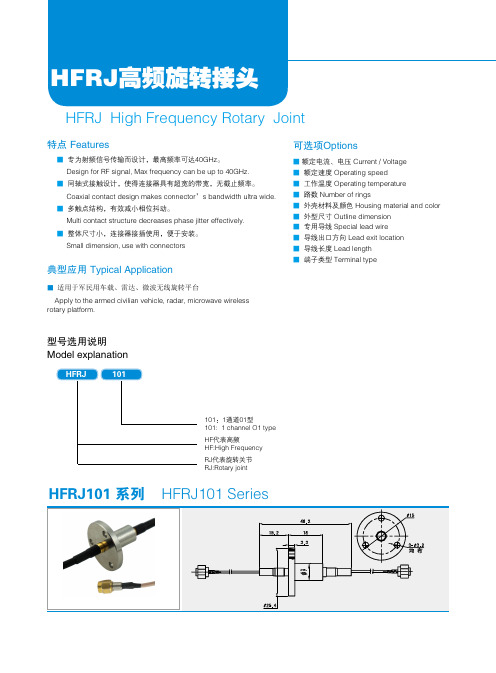
HFRJ高频旋转接头HFRJ High Frequency Rotary Joint■ 专为射频信号传输而设计,最高频率可达40GHz。
Design for RF signal, Max frequency can be up to 40GHz.■ 同轴式接触设计,使得连接器具有超宽的带宽,无截止频率。
Coaxial contact design makes connector’s bandwidth ultra wide.■ 多触点结构,有效减小相位抖动。
Multi contact structure decreases phase jitter effectively.■ 整体尺寸小,连接器接插使用,便于安装。
Small dimension, use with connectors特点 Features■ 额定电流、电压 Current / Voltage ■ 额定速度 Operating speed ■ 工作温度 Operating temperature ■ 路数 Number of rings■ 外壳材料及颜色 Housing material and color ■ 外型尺寸 Outline dimension ■ 专用导线 Special lead wire ■ 导线出口方向 Lead exit location ■ 导线长度 Lead length ■ 端子类型 Terminal type■ 适用于军民用车载、雷达、微波无线旋转平台Apply to the armed civilian vehicle, radar, microwave wireless rotary platform.可选项Options典型应用 Typical Application型号选用说明Model explanation101:1通道01型101: 1 channel O1 type HF代表高频HF:High Frequency RJ代表旋转关节RJ:Rotary jointHFRJ101 系列HFRJ101 Series工业滑环分册HFRJ102系列 SeriesSeriesSeriesHFRJ103系列HFRJ104系列HFRJ105系列工业滑环分册电气技术指标 Electrical dataHFRJ202系列电气技术指标 Electrical data。
AFR125减震说明书
AFR125减震说明书
1、官方油耗为
2、07升每百公里,发动机类型为强制风冷单缸四冲程,排量124ML,最大功率6、6KW,最大扭矩10牛米,符合国四排放标准。
车辆灯光除转向灯外均使用LED灯源,标配日间行车灯,大灯夜间铺路效果优秀,尾灯造型时尚犀利,转向灯带蜂鸣提示。
2、AFR远近灯光可以同时开启,标配超车灯按键。
仪表为数字液晶负显仪表,开启大灯时,仪表亮度自动降低。
该车仪表主要功能包含油量、速度、时钟、保养提醒,总里程与AB小计里程。
AFR 的手把握持感非常舒适,手把材料防滑耐脏,柔软有韧性。
3、刹车标配CBS联动刹车,单捏后刹,前刹可自动刹车,力度分配前三后七,前刹为双杠刹车,整体刹车性能优秀。
但是刹车时刹把会有空档行程,需要适应。
车辆后视镜自我感觉视野较小。
后脚踏设计,开合省力。
4、前减震配备防尘套,车头内部空间有密闭处理。
后减震可三段式调整,但自我感觉不明显。
踏板位置宽敞,但是没有斜踏设计。
边撑有静音设计,但是边撑脚蹬位置较小,不容易踢到,需要适应。
5、车辆前置储物可放杯架,仔细观察杯架机关有橡胶防滑处理,右侧储物格空间宽敞。
车辆钥匙处有防盗锁,USB接口为
5V2A,输出功率10W,中间挂钩可收纳。
IHF40-25-125
长沙自平衡多级泵厂IHF40-25-125氟塑料离心泵IHF40-25-125单级单吸式氟塑料合金化工离心泵(简称IHF40-25-125离心泵)是按国际标准并结合非金属泵的工艺设计制造。
泵体采用金属外壳内衬氟塑料,泵盖、叶轮均用金属嵌件外包氟塑料整体烧结压制而成,轴封采用外装式先进的波纹机械密封,静环选用或碳化硅,动环采用四氟填充材料,其耐腐耐磨密封性极好。
该泵具有耐腐、耐磨、耐高温、不老化、机械强度高、运转平稳、结构先进合理、密封性能严格可靠、拆卸检修方便、使用寿命长等优点。
化工生产中的腐蚀性介质输送、离子膜烧碱项目中的氯水废水处理和加酸工艺、有色金属冶炼中的电解液输送、汽车制造中的酸洗工艺,及制药、石油、电力、电镀、染料、农药、造纸、食品、纺织等众多行业,在多种温度条件下长期输送任意浓度的硫酸、盐酸、氢氟酸、硝酸、王水、强碱、强氧化剂、有机溶剂、还原剂等强腐蚀介质而毫不受损,是目前最受使用单位欢迎的泵类设备之一。
适用温度:-20℃~120℃;采用进口材料,其适用温度可达150℃。
启动与运行1、开机前应将泵内灌满须输送的液体或水,关闭出口阀门,接好电源;2、接通电源,检查泵的转向是否正确;3、缓慢开启出口阀门,调整到所需的性能点,机组试运转5~10 分钟,如无异常现象可投入正常运行;4、停机时,应先关闭泵的出口阀门,然后再切断电源;5、如果泵组在运行过程中发生汽蚀,必需在1 分钟内停机检查;6、如果泵组在运行时突然停电,必需立即关闭电源开关,并关闭出口阀门;7、泵组运行过程中,应经常检查泵和电机,发现异常的噪音和升温应立即停机检修;8、介质粘度对泵的性能有一定影响,当液体粘度发生变化时,泵性能也有所变化,使用过程中应当注意。
工作原理离心泵的主要过流部件有吸水室、叶轮和压水室。
吸水室位于叶轮的进水口前面,起到把液体引向叶轮的作用;压水室主要有螺旋形压水室(蜗壳式)、导叶和空间导叶三种形式;叶轮是泵的最重要的工作元件,是过流部件的心脏,叶轮由盖板和中间的叶片组成。
IHF50-32-125
IHF50-32-125氟塑料离心泵安 徽 博 特 泵 阀 制 造 有 限 公 司一、氟塑料离心泵用途及特点IHF50-32-125氟塑料离心泵广泛应用于:石油化工、制酸制碱、有色金属冶炼、汽车制造的酸洗工艺、稀土分离、农药、染料、医药、造纸、电镀、无线电等行 业,适用于输送清液或者含有少量颗粒(固含量≤10%)的腐蚀性介质。
氟塑料离心泵特点:IHF型氟塑料离心泵按国际标准设计,泵体采用金属外壳内衬氟塑料,叶轮及泵盖均采用金属嵌件外包氟塑料合金压制成型,轴封采用先进的外装式波纹管机械密封,静环选用99.9%氧化铝陶瓷,动环采用四氟填充材料 (或很据用户特殊工况专配其他材质),其特点是耐腐耐磨密封性好。
二、氟塑料离心泵型号意义IHF50-32-125IH: 国际标准化泵系列代号 32:泵出口口径是32mmF: 过流部件材质为氟塑料合金 125:叶轮名义直径是125mm50:泵进口口径是50mm三、氟塑料离心泵型号及参数转速n=2900r/min型号流量m³/h扬程m效率%汽蚀余量m电机功率kw整机质量kg IHF50-32-12512.52052 3.2 2.2110四、氟塑料离心泵使用范围1.耐压极限:耐压极限为1.0MPa,要注意泵的输出压力不能超过耐压极限。
2.使用温度范围:-20 ~100℃;环境温度变化范围:0~40℃;环境湿度变化范围:35~85%RH.3.如果工况使用温度在100℃~150℃范围内,其过流部件采用高温氟塑料制造。
4.可输送带有少量颗粒及结晶的介质(固含量≤10%),禁止输送会产生大量气泡的介质。
5.液体粘度对泵性能的影响:当液体粘度发生变化的时候,泵的性能也有所变化。
五、氟塑料离心泵使用前注意事项1、离心泵禁止空运装,泵运行时的最小流量:设计点35%。
2、如果泵运转时发生汽蚀,必须在1分钟内停机。
3、介质温度变化应控制在40℃以内,过高的温升/降可能导致泵零件的损坏。
C-2-HF125℃无卤阻燃热收缩管
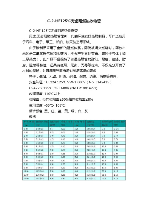
C-2-HF125℃无卤阻燃热收缩管C-2-HF 125℃无卤阻燃热收缩管用途:无卤阻燃热缩管是新一代的环境友好热缩制品,可广泛应用于汽车、电子、军工、船舶、航天航空等领域。
由于该制品采用了全新的阻燃体系,即使被明火燃烧时,释放出来的是二氧化碳气体和水蒸汽,不会产生其他有毒、腐蚀性气体(如二恶英类)。
此产品不但保持了普通热缩管的耐油、耐磨、绝缘、防腐、阻燃等特性,还具有低烟、无卤、无毒等优点。
不仅充分开发了材料的潜能,并可满足当前市场对制品环保的要求.特性:低烟、无卤、阻燃、耐油、耐磨、绝缘、防腐等特性。
安全认证:UL224 125℃ VW-1 600V(No .E142415)CSA22.2 125℃ OFT 600V (No.LR108142-1)收缩温度: 110℃以上收缩率:径向收缩率≥50%轴向收缩率≤8%使用温度: -55℃- 105℃标准颜色: 黑、红、蓝、黄、绿、白、灰规格C-2-HF 125℃无卤阻燃热收缩管用途:无卤阻燃热缩管是新一代的环境友好热缩制品,可广泛应用于汽车、电子、军工、船舶、航天航空等领域。
由于该制品采用了全新的阻燃体系,即使被明火燃烧时,释放出来的是二氧化碳气体和水蒸汽,不会产生其他有毒、腐蚀性气体(如二恶英类)。
此产品不但保持了普通热缩管的耐油、耐磨、绝缘、防腐、阻燃等特性,还具有低烟、无卤、无毒等优点。
不仅充分开发了材料的潜能,并可满足当前市场对制品环保的要求.特性:低烟、无卤、阻燃、耐油、耐磨、绝缘、防腐等特性。
安全认证:UL224 125℃ VW-1 600V(No .E142415)CSA22.2 125℃ OFT 600V (No.LR108142-1)收缩温度: 110℃以上收缩率:径向收缩率≥50%轴向收缩率≤8%使用温度: -55℃- 105℃标准颜色: 黑、红、蓝、黄、绿、白、灰规格(可根据客户需求提供其他规格的管材)产品性能C-2 125℃低温阻燃绝缘热收缩管用途: 电线端部、连接部、接线端子、焊点的绝缘防护和补强.特性:收缩温度低、阻燃、柔软。
74AHC125中文资料
1999 Sep 27
5
元器件交易网
Philips Semiconductors
Quad buffer/line driver; 3-state
MIN. MAX. UNIT
−0.5 +7.0 V
−0.5 +7.0 V
−
−20 mA
−
±20 mA
−
±25 mA
−
±75 mA
−65 +150 °C
−
500 mW
Notes 1. The input and output voltage ratings may be exceeded if the input and output current ratings are observed. 2. For SO packages: above 70 °C the value of PD derates linearly with 8 mW/K.
CODE SOT108-1 SOT402-1 SOT108-1 SOT402-1
1999 Sep 27
3
元器件交易网
Philips Semiconductors
Quad buffer/line driver; 3-state
Product specification
74AHC125; 74AHCT125
SO TSSOP
plastic plastic plastic plastic
PINNING
PIN 1, 4, 10 and 13 2, 5, 9 and 12 3, 6, 8 and 11 7 14
HFBR-1522中文资料
Features•Low cost fiber optic components •Enhanced digital links dc-5 MBd•Extended distance links up to 120 m at 40 kBd •Low current link: 6 mA peak supply current •Horizontal and vertical mounting •Interlocking feature •High noise immunity•Easy connectoring Simplex, Duplex, and Latching connectors•Flame retardant•Transmitters incorporate a 660 nm Red LED for easy visibility•Compatible with standard TTL circuitryApplications•Reduction of lightning/voltage transient susceptibility •Motor controller triggering•Data communications and local area networks•Electromagnetic Compatibility (EMC) for regulated systems: FCC, VDE, CSA, etc.•Tempest-secure data processing equipment •Isolation in test and measurement instruments•Error free signalling for industrial and manufacturing equipment•Automotive communications and control networks •Noise immune communication in audio and video equipmentDescriptionThe Versatile Link series is a complete family of fiber optic link components for applications requiring a low cost solution. The HFBR-0501 series includes transmitters, receivers, connectors and cable specified for easy design. This series of components is ideal for solving problems with voltage isolation/insulation,EMI/RFI immunity or data security. The optical link design is simplified by the logic compatible receivers and complete specifications for each component. The key optical and electrical parameters of links configured with the HFBR-0501 family are fully guaranteed from 0° to 70°C.A wide variety of package configurations and connectors provide the designer with numerous mechanical solutions to meet application requirements. The transmitter and receiver components have been designed for use in high volume/low cost assembly processes such as auto insertion and wave soldering.Transmitters incorporate a 660 nm LED. Receivers include a monolithic dc coupled, digital IC receiver with open collector Schottky output transistor. An internal pullup resistor is available for use in the HFBR-25X1/2/4receivers. A shield has been integrated into the receiver IC to provide additional, localized noise immunity.Internal optics have been optimized for use with 1 mm diameter plastic optical fiber. Versatile Link specifications incorporate all connector interface losses. Therefore,optical calculations for common link applications aresimplified.HFBR-0501 SeriesVersatile LinkThe Versatile Fiber Optic ConnectionData SheetHFBR-0501 Series Part Number GuideHFBR X5XX1 = Transmitter2 = Receiver5 = 600 nm Transmitter and Receiver Products1 = 5 MBd High Performance Link2 = 1 MBd High Performance Link3 = 40 kBd Low Current/Extended Distance Link 2 = Horizontal Package4 = 1 MBd Standard Link 3 = Vertical Package6 = 155 MBd Receiver7 = 155 MBd Transmitter8 = 10 MBd High Performance LinkEvaluation KitHFBR-0501 1 MBd Versatile Link:This kit contains: HFBR-1524 Tx, HFBR-2524 Rx,polishing kit, 3 styles of plastic connectors, Bulkhead feedthrough, 5 meters of 1 mm diameter plastic cable,lapping film and grit paper, and HFBR-0501 data sheet.Application LiteratureApplication Note 1035 (Versatile Link)VALOX ® is a registered trademark of the General Electric Corporation.Package and Handling InformationThe compact Versatile Link package is made of a flame retardant VALOX ® UL 94 V-0 material (UL file # E121562)and uses the same pad layout as a standard, eight pin dual-in-line package. Vertical and horizontal mountable parts are available. These low profile Versatile Link packages are stackable and are enclosed to provide a dust resistant seal. Snap action simplex, simplex latching, duplex, and duplex latching connectors are offered with simplex or duplex cables.Package OrientationPerformance and pinouts for the vertical and horizontal packages are identical. To provide additional attachment support for the vertical Versatile Link housing, the designer has the option of using a self-tapping screw through a printed circuit board into a mounting hole at the bottom of the package. For most applications this is not necessary .Package Housing ColorVersatile Link components and simplex connectors are color coded to eliminate confusion when making connections. Receivers are blue and transmitters are gray, except for the HFBR-15X3 transmitter, which is black.Link Selection Guide(Links specified from 0 to 70°C, for plastic optical fiber unless specified.)Signal Rate Distance (m) 25°C Distance (m)TransmitterReceiver 40 kBd 120110HFBR-1523HFBR-25231 MBd 2010HFBR-1524HFBR-25241 MBd 5545HFBR-1522HFBR-25225 Mbd 3020HFBR-1521HFBR-2521HandlingVersatile Link components are auto-insertable. When wave soldering is performed with Versatile Link components, the optical port plug should be left in to prevent contamination of the port. Do not use reflow solder processes (i.e., infrared reflow or vapor-phase reflow). Nonhalogenated water soluble fluxes (i.e., 0% chloride), not rosin based fluxes, are recom-mended for use with Versatile Link components. Versatile Link components are moisture sensitive devices and are shipped in a moisture sealed bag. If the components are exposed to air for an extended period of time, they may require a baking step before the soldering process. Refer to the special labeling on the shipping tube for details.Recommended Chemicals for Cleaning/Degreasing Alcohols: methyl, isopropyl, isobutyl. Aliphatics: hexane, heptane, Other: soap solution, naphtha.18.8 0.7407.6 (0.30)Do not use partially halogenated hydrocarbons such as1,1.1 trichloroethane, ketones such as MEK, acetone,chloroform, ethyl acetate, methylene dichloride, phenol,methylene chloride, or N-methylpyrolldone. Also, Avagodoes not recommend the use of cleaners that usehalogenated hydrocarbons because of their potentialenvironmental harm.Mechanical DimensionsHorizontal Modules Vertical ModulesVersatile Link Printed Board Layout DimensionsHorizontal Module Vertical Module Interlocked (Stacked) Assemblies (refer to Figure 1)Horizontal packages may be stacked by placing units with pins facing upward. Initially engage the inter-locking mechanism by sliding the L bracket body from above into the L slot body of the lower package. Use a straight edge, such as a ruler, to bring all stacked units into uniform alignment. This technique prevents potential harm that could occur to fingers and hands of assemblers from the package pins. Stacked horizontal packages can be disengaged if necessary. Repeated stacking and unstacking causes no damage to individual units.To stack vertical packages, hold one unit in each hand, with the pins facing away and the optical ports on the bottom. Slide the L bracket unit into the L slot unit. The straight edge used for horizontal package alignment is not needed.Stacking Horizontal ModulesFigure 1. Interlocked (stacked) horizontal or vertical packagesDIMENSIONS IN MILLIMETERS (INCHES).Figure 2. Typical 5 MBd interface circuitFigure 4. Guaranteed system performance with improved cable (HFBR-15X1/25X1)Figure 3. Guaranteed system performance with standard cable (HFBR-15X1/25X1)5 MBd Link (HFBR-15X1/25X1)Notes:1.The propagation delay for one metre of cable is typically 5 ns.2.Typical propagation delay is measured at P R = -15 dBm.3.Estimated typical link life expectancy at 40°C exceeds 10 years at 60 mA.Figure 5. 5 MBd propagation delay test circuitFigure 8. Typical link propagation delay vs. optical powerFigure 7. Typical link pulse width distortion vs. optical powerFigure 6. Propagation delay test waveformst D – P U L S E W I D T H D I S T O R T I O N – n sP R – INPUT OPTICAL POWER – dBm t p – P R O P A G A T I O N D E L A Y –n sPR – INPUT OPTICAL POWER – dBmPin #Function 1Anode 2Cathode 3Open 4Open5Do not connect 8Do not connectNote: Pins 5 and 8 are for mounting and retaining purposes only. Do not electrically connect these pins.HFBR-15X1 TransmitterAll HFBR-15XX LED transmitters are classified as IEC 825-1 Accessible Emission Limit (AEL) Class 1based upon the current proposed draft scheduled to go into effect on January 1, 1997. AEL Class 1 LED devices are considered eye safe. Contact your local Avago sales representative for more information.Absolute Maximum RatingsNotes:1. 1.6 mm below seating plane.2. Recommended operating range between 10 and 750 mA.3. 1 µs pulse, 20 µs period.Figure 9. Typical forward voltage vs. drive current Figure 10. Normalized typical output power vs. drive currentV F – F O R W A R D V O L T A G E – V21.81.61.4I Fdc – TRANSMITTER DRIVE CURRENT (mA)101.71.510070°C25°C0°CP T – N O R M A L I Z E D O U T P U T P O W E R – d B25-5-20I Fdc – TRANSMITTER DRIVE CURRENT (mA)100-15100-10Transmitter Electrical/Optical Characteristics 0°C to 70°C unless otherwise specified.Notes:1.Measured at the end of 0.5 m standard fiber optic cable with large area detector.2.Optical power, P (dBm) = 10 Log [P(µW)/1000 µW].3.Rise and fall times are measured with a voltage pulse driving the transmitter and a series connected 50 Ω load. A wide bandwidth optical to electrical waveform analyzer, terminated to a 50 Ω input of a wide bandwidth oscilloscope, is used for this response time measurement.Pin #Function 1V O2Ground 3V CC 4R L5Do not connect 8Do not connectNote: Pins 5 and 8 are for mounting and retaining purposes only. Do not electrically connect these pins.HFBR-25X1 ReceiverL CC OAbsolute Maximum RatingsNotes:1.1.6 mm below seating plane.2.It is essential that a bypass capacitor 0.01 µF be connected from pin 2 to pin 3 of the receiver. Total lead length between both ends of the capacitor and the pins should not exceed 20 mm.Receiver Electrical/Optical Characteristics0°C to 70°C, 4.75 V ≤V CC ≤5.25 V unless otherwise specifiedNotes:1.Optical flux, P (dBm) = 10 Log [P (µW)/1000 µW].2.Measured at the end of the fiber optic cable with large area detector.3.R L is open.4.Pulsed LED operation at I F > 80 mA will cause increased link t PLH propagation delay time. This extended t PLH time contributes to increased pulse width distortion of the receiver output signal.1 MBd Link(High Performance HFBR-15X2/25X2, Standard HFBR-15X4/25X4)System Performance Under recommended operating conditions unless otherwise specified.Notes:1.For I FPK > 80 mA, the duty factor must be such as to keep I Fdc≤80 mA. In addition, for I FPK > 80 mA, the following rules for pulse width apply:I FPK≤160 mA: Pulse width ≤1 msI FPK > 160 mA: Pulse width ≤1 µS, period ≥20 µS.2.The propagation delay for one meter of cable is typically 5 ns.3.Estimated typical link life expectancy at 40°C exceeds 10 years at 60 mA.4.Pulsed LED operation at I FPK > 80 mA will cause increased link t PLH propagation delay time. This extended t PLH time contributes to increased pulsewidth distortion of the receiver output signal.Figure 11. Required 1 MBd interface circuitFigure 15. Guaranteed system performance for the HFBR-15X2/25X2 Link with improved cableFigure 14. Guaranteed system performance for the HFBR-15X2/25X2 Link with standard cable Figure 13. Guaranteed system performance for the HFBR-15X4/25X4 Link with improved cableFigure 12. Guaranteed system performance for the HFBR-15X4/25X4 Link with standard cableI F – F O R W A R D C U R R E N T (m A )– CABLE LENGTH – METRESI F – F O R W A R D C U R R E N T (m A )– CABLE LENGTH – METRESThe HFBR-25X2 receiver can not be overdriven when using the required interface circuit shown in Figure 11.Figure 17. Pulse width distortion vs. optical power Figure 16. 1 MBd propagation delay test circuitFigure 19. Propagation delay test waveformsFigure 18. Typical link propagation delay vs. optical powert D – P U L S E W I D T H D I S T O R T I O N – n sP R – INPUT OPTICAL POWER – dBm t p – P R O P A G A T I O N D E L A Y – nsP R – INPUT OPTICAL POWER – dBmPin #Function 1Anode 2Cathode 3Open 4Open5Do not connect 8Do not connectNote: Pins 5 and 8 are for mounting and retaining purposes only. Do not electrically connect these pins.HFBR-15X2/15X4 TransmittersAll HFBR-15XX LED transmitters are classified as IEC 825-1 Accessible Emission Limit (AEL) Class 1based upon the current proposed draft scheduled to go into effect on January 1, 1997. AEL Class 1 LED devices are considered eye safe. Contact your Avago sales representative for more information.Absolute Maximum RatingsNotes:1.1.6 mm below seating plane.2.Recommended operating range between 10 and 750 mA.3.1 µs pulse, 20 µs period.Transmitter Electrical/Optical Characteristics 0°C to 70°C unless otherwise specified.Note:1.Rise and fall times are measured with a voltage pulse driving the transmitter and a series connected 50 Ω load. A wide bandwidth optical to electrical waveform analyzer, terminated to a 50 Ω input of a wide bandwidth oscilloscope, is used for this response time measurement.Pin #Function 1V O2Ground 3V CC 4R L5Do not connect 8Do not connectNote: Pins 5 and 8 are for mounting and retaining purposes only. Do not electrically connect these pins.HFBR-25X2/25X4 ReceiversL CC OAbsolute Maximum RatingsNotes:1.1.6 mm below seating plane.2.It is essential that a bypass capacitor 0.01 µF be connected from pin 2 to pin 3 of the receiver. Total lead length between both ends of the capacitor and the pins should not exceed 20 mm.Receiver Electrical/Optical Characteristics 0°C to 70°C, 4.75 V ≤V CC ≤5.25 V unless otherwise specified.Notes:1.Measured at the end of the fiber optic cable with large area detector.2.Pulsed LED operation at I F > 80 mA will cause increased link t PLH propagation delay time. This extended t PLH time contributes to increased pulse width distortion of the receiver output signal.3.The LED drive circuit of Figure 11 is required for 1 MBd operation of the HFBR-25X2/25X4.4.Optical flux, P (dBm) = 10 Log [P(µW)/1000 µW].5.R L is open.Figure 20. Typical 40 kBd interface circuitFigure 22. Guaranteed system performance with improved cableFigure 21. Guaranteed system performance with standard cable40 kBd LinkSystem Performance Under recommended operating conditions unless otherwise specified.Parameter SymbolMin.Typ.Max.Units ConditionsRef.Data Rate dc 40kBd BER ≤10-9, PRBS: 27 - 1Link Distance 1341m I Fdc = 2 mA Fig. 21(Standard Cable)94138m I Fdc = 60 mA Note 1Link Distance 1545m I Fdc = 2 mA Fig. 22(Improved Cable)111154m I Fdc = 60 mANote 1Propagation t PLH 4µs R L = 3.3 k Ω, C L = 30 pF Fig. 22, 25Delayt PHL 2.5µs P R = -25 dBm, 1 m fiber Note 2Pulse Widtht D7µs-39 ≤P R ≤- 14 dBm Fig. 23, 24Distortion t PLH -t PHLR L = 3.3 k Ω, C L = 30 pFNotes:1.Estimated typical link life expectancy at 40°C exceeds 10 years at 60 mA.2.The propagation delay for one metre of cable is typically 5 ns.Figure 23. 40 kBd propagation delay test circuitFigure 26. Propagation delay test waveformsFigure 25. Typical link propagation delay vs. optical powerFigure 24. Typical link pulse width distortion vs. optical power 53421-40-28-34-10t – P U L S E W I D T H D I S T O R T I O N – µsD 60-22-16 P – INPUT OPTICAL POWER, dBm RPin #Function 1Anode 2Cathode 3Open 4Open5Do not connect 8Do not connectNote: Pins 5 and 8 are for mounting and retaining purposes only. Do not electrically connect these pins.HFBR-15X3 TransmitterAll HFBR-15XX LED transmitters are classified as IEC 825-1 Accessible Emission Limit (AEL) Class 1based upon the current proposed draft scheduled to go into effect on January 1, 1997. AEL Class 1 LED devices are considered eye safe. Contact your Avago sales representative for more information.Absolute Maximum RatingsNotes:1.1.6 mm below seating plane.2.Recommended operating range between 10 and 750 mA.3.1 µs pulse, 20 µs period.Transmitter Electrical/Optical Characteristics 0°C to 70°C unless otherwise specified.For forward voltage and output power vs. drive current graphs.Note:1. Rise and fall times are measured with a voltage pulse driving the transmitter and a series connected 50 Ω load. A wide bandwidth optical to electrical waveform analyzer, terminated to a 50 Ω input of a wide bandwidth oscilloscope, is used for this response time measurement.Pin #Function 1V O2Ground 3Open 4V CC5Do not connect 8Do not connectNote: Pins 5 and 8 are for mounting and retaining purposes only. Do not electrically connect these pins.HFBR-25X3 ReceiverCC ONotes:1.Measured at the end of the fiber optic cable with large area detector.2.Optical flux, P (dBm) = 10 Log P(µW)/1000 µW.3.Because of the very high sensitivity of the HFBR-25X3, the digital output may switch in response to ambient light levels when a cable is not occupying the receiver optical port. The designer should take care to filter out signals from this source if they pose a hazard to the system.4.Including current in 3.3 k pull-up resistor.Absolute Maximum RatingsNotes:1.1.6 mm below seating plane.2.It is essential that a bypass capacitor 0.01 µF be connected from pin 2 to pin 3 of the receiver.For product information and a complete list of distributors, please go to our website: Avago, Avago Technologies, and the A logo are trademarks of Avago Technologies Limited in the United States and other countries. Data subject to change. Copyright © 2008 Avago Technologies Limited. All rights reserved. Obsoletes 5968-1712E5988-1765EN January 30, 2008。
safur125f500制动电阻参数

safur125f500制动电阻参数
Safur125f500制动电阻是一种常见的电子元件,用于控制电机的制动过程。
它具有多个参数,包括电阻值、功率、温度系数等,这些参数对于电机的制动性能至关重要。
我们来看一下Safur125f500制动电阻的电阻值。
电阻值是指电阻器对电流的阻碍程度,通常用欧姆(Ω)来表示。
Safur125f500制动电阻的电阻值可以根据具体的需求进行选择,不同的电机可能需要不同的电阻值来实现最佳制动效果。
制动电阻的功率是指电阻器能够耗散的功率。
在制动过程中,电机会将动能转化为电能并存储在电容器或电池中。
当需要制动时,电机会将电能释放出来,而制动电阻则会将这部分电能转化为热能耗散掉。
因此,制动电阻的功率需要根据电机的功率及制动过程的需求来选择。
温度系数是指电阻值随温度变化的程度。
不同的电阻器材料具有不同的温度系数,这会影响到制动电阻的性能稳定性。
Safur125f500制动电阻通常采用具有较低温度系数的材料,以保证在不同温度环境下的稳定性。
总的来说,Safur125f500制动电阻是一种重要的电子元件,它的参数决定了电机的制动性能。
在选择和应用该电阻时,需要考虑电阻值、功率和温度系数等因素。
只有合理选择和使用制动电阻,才能
确保电机的制动过程安全可靠,提高设备的性能和寿命。
HFR1000软起动器系列说明书

250
153
HFR1045(45KW)
250
153
HFR1055(55KW)
250
153
HFR1075(75KW)
510
260
HFR1090(90KW)
510
260
HFR1110(110KW)
510
260
HFR1132(132KW)
510
260
HFR1160(160KW)
510
260
HFR1200(200KW)
通过 ISO9001 质量体系认证
惠丰软起动器
HFR1000 系列 15~315KW
使用手册
序言
HFR 软起动器用户手册
感谢您选用惠丰软起动器! 烟台惠丰电子有限公司将以 完美的质量, 竭诚的服务, 给您最真挚的回报。
HFR1000 系列软起动器应用现代控制原理,采用模块化设计、DSP 控制,在采用 高品质材料和元器件的基础上应用先进的贴片生产工艺制造而成,它是集数字技术、 计算机技术、现代自控技术于一体的高科技产品,具有高性能、高品质、小体积等特 点,可广泛应用于各行业的三相交流电动机起动和保护。
510
260
HFR1220(220KW)
590
360
HFR1250(250KW)
590
360
HFR1280(280KW)
590
360
HFR1315(315KW)
590
360Байду номын сангаас
安装尺寸(单位:mm)
规格型号
E(高)
F(宽)
HFR1015
219
140
HFR1022
219
140
豪爵vf125说明书
豪爵vf125说明书原先两侧的黄色反光板已经被替换为LED牌照灯,联动原车日行灯,覆盖范围90度,配合大灯罩内的LED日行灯警示效果很好。
原车的35W欧司朗卤素灯几乎就是个蜡烛,当然我完全理解一些朋友说那个亮度足够使用,因为他们晚上骑得不快,视力也相对较好,对于我这种有点近视加散光的人来说那点亮度是在危险。
这个35W的LED小透镜安装调整好后切线干净左低右平不会晃到对方司机的眼睛,缺点是远光比较差劲,遇到远光狗不能很好的提示对方。
此类小透镜都是一样的,只要不是便宜的离谱都很耐用,原车插头直接插上无损安装,方法和VF100几乎一模一样无痕测车-VF100改灯。
原车闪光器在仪表旁边需要拆开面罩才能替换,如果不换闪光器直接改灯需要注意灯泡的功率,最好每个灯泡的功率在7瓦以上12瓦一下,如果使用双闪功能则四个灯泡的总功率不超过40瓦。
转向灯泡是个坑,也许你永远用不坏也许你刚装上就坏,功率太大会导致闪光器光速报废,功率太小闪光器将不会工作。
双闪加转向的开关是公模件,需要配一个转接线才能正常使用,安装很简单。
可能是我安装了风挡的原因本地几个车友也觉得比例出奇的协调,加上平时几乎没有带人的需求尾箱在不影响坐垫开合的前提下几乎就是挨着坐垫固定。
尾箱装车后双手离把车不抖,后座的人靠在靠背上很稳,但因为安装位置侵占了很多后座空间所以推荐安装在略靠后的位置上,这样也就不需要切割货架的后扶手。
155元的价格说实话很贵,而且自带的两个支架固定螺丝质量太差,强烈建议各位有想法的朋友自己买两颗正儿八经的304不锈钢螺丝,规格M6-100。
这玩意有两个好处,一是护着手,二个就是冬天不需要戴太厚的保暖手套,因为风不会吹在手上所以手部失温的速度会很慢。
总体安装简单调整不难,南方的朋友除非很强调安全不然没什么安装的必要性。
风挡在南方似乎也没什么必要,但我这里春秋天的晚上就能冻si个人。
无须太高,脖子以下不直接迎风即可,太高影响视线降低操控增加油耗得不偿失。
tmcf125ab参数

tmcf125ab参数一、概述tmcf125ab是一款高性能的磁性薄膜材料,广泛应用于电子、通信、航空航天等领域。
其具有优异的磁性能、良好的机械性能和稳定的化学性质,是制造高精度、高性能磁性器件的重要原材料。
本文将对tmcf125ab的参数进行详细的介绍。
二、磁性能参数1.剩磁感应强度(Br):tmcf125ab的剩磁感应强度较高,可以达到1.25T(特斯拉)。
这使得tmcf125ab在制作高灵敏度磁性器件方面具有显著的优势。
2.饱和磁化强度(Ms):饱和磁化强度是磁性材料的一个重要参数,表示磁性材料在一定磁场下能够达到的最大磁化强度。
tmcf125ab的饱和磁化强度很高,可以达到140000A/m(安培/米)。
3.矫顽力(Hc):矫顽力是磁性材料的一个重要参数,表示磁性材料克服退磁效应所需的磁场强度。
tmcf125ab的矫顽力较高,可以达到2400A/m (安培/米)。
三、物理性能参数1.密度:tmcf125ab的密度较高,可以达到7.65g/cm³(克/立方厘米)。
这有助于提高磁性器件的稳定性和可靠性。
2.热稳定性:tmcf125ab具有良好的热稳定性,可以在较高的温度下保持稳定的磁性能。
其热稳定性可以在一定范围内通过热处理进行调整。
四、机械性能参数1.硬度:tmcf125ab的硬度较高,可以采用常用的加工方法进行加工。
其硬度取决于制备工艺和热处理条件。
2.韧性:tmcf125ab具有良好的韧性,可以在一定程度上承受冲击和振动。
这有助于提高磁性器件的可靠性和稳定性。
AMF25中文说明书(全)
发动机保护---------------------------------------------------------------------------------35
传感器特性--------------------------------------------------------------------------------42
IOM模块---------------------------------------------------------------------------------42
怎么看和编辑设定点?-------------------------------------------------------------------------51
怎么寻找动作的警报?------------------------------------------------------------------------51测量屏幕容--------------------------------------------------------------------------------52
模拟输入-----------------------------------------------------------------------------------29
设定点-------------------------------------------------------------------------------------31
裂行125参数
裂行125参数裂行125是一款由日本品牌川崎重工生产的摩托车,其参数在同级别的车型中表现出众,具有出色的性能和设计。
本文将从外观、动力、悬挂、制动、安全等方面详细介绍裂行125的参数。
外观裂行125的整车造型流畅,线条简洁,外观设计上具有典型的川崎重工风格。
车身采用大量的铝合金材料,整体重量比同级别的车型轻,且具有更好的稳定性。
前脸采用LED灯组,不仅具有更好的亮度,而且寿命更长。
车身配有大面积的散热孔,能够有效降低车辆温度,提高发动机的工作效率。
整车的质感和细节处理都非常出色,让人看起来非常舒适。
动力裂行125搭载一台125cc水冷四冲程单缸发动机,最大功率达到15马力,最大扭矩为12.5牛米,综合燃油消耗量为3.2升/100公里。
该发动机采用了多项先进技术,如液压升程可调式凸轮轴、双喷射嘴燃油喷射系统、电子点火等,使得发动机动力输出更加平稳,燃油经济性更好。
另外,裂行125还配备了6档手动变速器,能够更好地满足驾驶者的需求。
悬挂裂行125采用了倒立式前叉和后单臂悬挂系统,前后悬挂都配备了防倾杆,提高了车辆的稳定性和安全性。
前叉的行程为120mm,后悬挂为132mm,悬挂系统的调校非常适合日常使用和运动驾驶。
此外,裂行125还配备了前后液压式碟刹,制动性能非常出色。
制动裂行125的制动系统采用了前后液压式碟刹,前刹车盘直径为290mm,后刹车盘直径为220mm,具有更好的制动效果和稳定性。
制动系统还配备了ABS防抱死系统,能够更好地防止车轮锁死,提高了行车安全性。
安全裂行125的安全配置非常齐全,配备了ABS防抱死系统、前后液压式碟刹、防倾杆等多项安全设备。
此外,裂行125还采用了全新的车身结构设计,能够有效提高车身的稳定性和抗扭性,提高了行车安全性。
车身还配备了LED大灯和LED尾灯,不仅提高了夜间行车的安全性,而且寿命更长。
总结裂行125不仅具有出色的外观设计,而且在动力、悬挂、制动、安全等方面也表现出众。
- 1、下载文档前请自行甄别文档内容的完整性,平台不提供额外的编辑、内容补充、找答案等附加服务。
- 2、"仅部分预览"的文档,不可在线预览部分如存在完整性等问题,可反馈申请退款(可完整预览的文档不适用该条件!)。
- 3、如文档侵犯您的权益,请联系客服反馈,我们会尽快为您处理(人工客服工作时间:9:00-18:30)。
HIGH VOLTAGE FAST RECOVERY RECTIFIERS
DO - 41
0.107 (2.7) 0.080 (2.0)
1.00 (25.4) MIN.
0.205 (5.2) 0.166 (4.2)
MECHANICAL DATA :
* Case : DO-41 Molded plastic * Epoxy : UL94V-O rate flame retardant * Lead : Axial lead solderable per MIL-STD-202, Method 208 guaranteed * Polarity : Color band denotes cathode end * Mounting position : Any * Weight : 0.34 gram
10 TJ = 100 °C
REVERSE CURRENT, MICROAMPERES
1.0
0.1
0.1 TJ = 25 °C
0.01 0 1.0 2.0 3.0 4.0 5.0 6.0 7.0 8.0 9.0 10.0
0.01 0 20 40 60 80 100 120 140
FORWARD VOLTAGE, VOLTS
0.034 (0.86) 0.028 (0.71)
1.00 (25.4) MIN.
Dimensions in inches and ( millimeters )
MAXIMUM RATINGS AND ELECTRICAL CHARACTERISTICS
Rating at 25 °C ambient temperature unless otherwise specified. Single phase, half wave, 60 Hz, resistive or inductive load. For capacitive load, derate current by 20%.
8.3 ms SINGLE HALF SINE WAVE Ta = 50 °C 24
200
150
18
100
12
50 60Hz RESISTIVE OR INDUCTIVE LOAD 0 0 25 50 75 100 125 150 175
6
0
1
2
4
6
10
20
40
60 100
AMBIENT TEMPERATURE, ( °C)
Page 1 of 2
Rev. 02 : March 24, 2005
元器件交易网
RATING AND CHARACTERISTIC CURVES ( HFR125 - HFR130 )
FIG.1 - REVERSE RECOVERY TIME CHARACTERISTIC AND TEST CIRCUIT DIAGRAM
RATING
Maximum Repetitive Peak Reverse Voltage Maximum RMS Voltage Maximum DC Blocking Voltage Maximum Average Forward Current Ta = 50°C
SYMBOL
VRRM VRMS VDC IF(AV)
1 cm
FIG.2 - DERATING CURVE FOR OUTPUT RECTIFIED CURRENT AVERAGE FORWARD OUTPUT CURRENT, mA
250 30
FIG.3 - MAXIMUM NON-REPETITIVE PEAK FORWARD SURGE CURRENT PEAK FORWARD SURGE CURRENT, AMPERES
HFR125
2500 1750 2500 250
HFR130
3000 2100 3000
UNIT
V V V mA
Maximum Peak Forward Surge Current 8.3ms Single half sine wave Superimposed on rated load (JEDEC Method) Maximum Peak Forward Voltage at IFM = 250 mA. Maximum DC Reverse Current at Rated DC Blocking Voltage Ta = 25°C Ta = 100°C VF IR IR(H) Trr TJ TSTG 250 - 40 to + 150 - 40 to + 150 5.0 1.0 20 200 7.0 V µA µA ns °C °C IFSM 30 A
50 Ω 10 Ω + 0.5 D.U.T. 50 Vdc (approx ) 1Ω PULSE GENERATOR ( NOTE 2 ) OSCILLOSCOPE ( NOTE 1 ) 0 - 0.25 Trr
+
- 1.0 A SET TIME BASE FOR 50/100 ns/cm
NOTES : 1. Rise Time = 7 ns max., Input Impedance = 1 megaohm, 22 pF. 2. Rise time = 10 ns max., Source Impedance = 50 ohms. 3. All Resistors = Non-inductive Types.
元器件交易网
HFR125 - HFR130
PRV : 2500 - 3000 Volts Io : 250 mA.
FEATURES :
* * * * * * * High current capability High surge current capability High reliability Low reverse current Low forward voltage drop Fast switching for high efficiency Pb / RoHS Free
NUMBER OF CYCLES AT 60Hz
FIG.4 - TYPICAL FORWARD CHARACTERISTICS
20
FIG.5 - TYPICAL REVERSE CHARACTERISTICS
FORWARD CURRENT, AMPERES
10 Pulse Width = 300 µs 2% Duty Cycle TJ = 25 °C 1.0 HVR125 HVR130
PERCENT OF RATED REVERSE VOLTAGE,March 24, 2005
Maximum Reverse Recovery Time ( Note 1 ) Junction Temperature Range Storage Temperature Range
Note :
( 1 ) Reverse Recovery Test Conditions : IF = 0.5 A, IR = 1.0 A, Irr = 0.25 A.
