简单的标准访控列表(GNS3模拟)
三层交换机配置ACL(访问控制列表)

三层交换机配置ACL(访问控制列表)说明:书本上讲述的ACL主要是应用在路由器上,但现在三层交换机在大中型企业中的应用越来越广泛,三层交换机因拥有路由器的功能而逐渐代替路由器。
ACL访问控制列表是构建安全规范的网络不可缺少的,但在三层交换机上配置ACL却不为一些刚进企业的初级网络管理维护人员所知。
在这里我介绍一下在三层交换机上配置ACL的试验过程。
试验拓扑介绍:三层交换机上配置本地Vlan 实现下层接入层交换机不同Vlan互通。
PC1 192.168.20.10 VLAN 192.168.20.1PC2 192.168.30.20 VLAN 192.168.30.1PC3 192.168.40.30 VLAN 192.168.40.1PC4 192.168.50.40 VLAN 192.168.50.1F0/1 192.168.70.2 (开启路由功能)路由器上配置F0/0 192.168.60.1 PC5 192.168.60.50F0/1 192.168.70.1试验步骤:1、在二层交换机上把相应的PC加入VLAN查看交换机Switch0Switch0(config)#show run!interface FastEthernet0/1switchport access vlan 2!interface FastEthernet0/2switchport access vlan 3!查看交换机Switch1Switch1#show run!interface FastEthernet0/3switchport access vlan 4!interface FastEthernet0/4switchport access vlan 5!2、在三层交换机上配置相应的本地VALNSwitch(config)#inter vl 2Switch(config-if)#ip add 192.168.20.1 255.255.255.0 Switch(config-if)#no shutSwitch(config)#inter vl 3Switch(config-if)#ip add 192.168.30.1 255.255.255.0 Switch(config-if)#no shutSwitch(config)#inter vl 4Switch(config-if)#ip add 192.168.40.1 255.255.255.0 Switch(config-if)#no shutSwitch(config)#inter vl 5Switch(config-if)#ip add 192.168.50.1 255.255.255.0 Switch(config-if)#no shutSwitch(config-if)#exi在接口itnerface f0/1上开启路由接口Switch(config)#inter f0/1Switch(config-if)#no switchport3、在二层交换机和三层交换机之间开启中继链路4、在路由器和三层交换机上配置动态路由协议RIP Router(config)#router ripRouter(config)#network 192.168.60.0Router(config)# network 192.168.70.0三层交换机上配置Switch(config)#router ripSwitch(config-router)#neSwitch(config-router)#network 192.168.70.0Switch(config-router)#network 192.168.20.0Switch(config-router)#network 192.168.30.0Switch(config-router)#network 192.168.40.0Switch(config-router)#network 192.168.50.0Switch(config-router)#5、验证各PC互通PC>ping 192.168.30.20Pinging 192.168.30.20 with 32 bytes of data:Request timed out.Reply from 192.168.30.20: bytes=32 time=110ms TTL=126Reply from 192.168.30.20: bytes=32 time=110ms TTL=126Reply from 192.168.30.20: bytes=32 time=125ms TTL=126Ping statistics for 192.168.30.20:Packets: Sent = 4, Received = 3, Lost = 1 (25% loss),Approximate round trip times in milli-seconds:Minimum = 110ms, Maximum = 125ms, Average = 115msPC>ping 192.168.40.30Pinging 192.168.40.30 with 32 bytes of data:Reply from 192.168.40.30: bytes=32 time=94ms TTL=126Reply from 192.168.40.30: bytes=32 time=125ms TTL=126Reply from 192.168.40.30: bytes=32 time=125ms TTL=126Reply from 192.168.40.30: bytes=32 time=109ms TTL=126Ping statistics for 192.168.40.30:Packets: Sent = 4, Received = 4, Lost = 0 (0% loss),Approximate round trip times in milli-seconds:Minimum = 94ms, Maximum = 125ms, Average = 113ms6、在三层交换机上配置ACL注意如果设置不同VALN的PC之间不能互通,则应用的接口应为VLAN对应的本地Llan接口。
GNS3模拟的硬件列表

Hardware emulated by GNS3Cisco 1700 Series1700s have one or more interfaces on the motherboard, 2 subslots for WICs (excepting on 1710s), an no NM slots.1710∙ 1 FastEthernet and 1 Ethernet fixed ports (CISCO1710-MB-1FE-1E).∙WIC slots: 0∙Note that interfaces do not use a slot designation (e.g. “f0”)1720, 1721 and 1750∙ 1 FastEthernet fixed port (C1700-MB-1ETH).∙WIC slots: 2 (maximum of 2 Ethernet ports or 4 serial ports).∙Note that interfaces do not use a slot designation (e.g. “f0”)1751 and 1760∙ 1 FastEthernet fixed port (C1700-MB-1ETH).∙WIC slots: 2 (maximum of 2 Ethernet ports or 4 serial ports).WIC cards∙WIC-1T (1 serial port)∙WIC-2T (2 serial ports)∙WIC-1ENET (1 Ethernet ports)Cisco 2600 Series2600s have one or more interfaces on the motherboard, 2 subslots for WICs and 1 Network Module (NM) slot.2610∙ 1 Ethernet fixed port (CISCO2600-MB-1E).∙NM slots: 1 (maximum of 4 Ethernet ports or 16 FastEthernet ports).∙WIC slots: 3 (maximum of 6 serial ports).2611∙ 2 Ethernet fixed ports (CISCO2600-MB-2E).∙NM slots: 1 (maximum of 4 Ethernet ports or 16 FastEthernet ports).∙WIC slots: 3 (maximum of 6 serial ports).2610XM, 2620, 2620XM and 2650XM∙ 1 FastEthernet fixed port (CISCO2600-MB-1FE).∙NM slots: 1 (maximum of 4 Ethernet ports or 16 FastEthernet ports).∙WIC slots: 3 (maximum of 6 serial ports).2611XM, 2621, 2621XM and 2651XM∙ 2 FastEthernet fixed ports (CISCO2600-MB-2FE).∙NM slots: 1 (maximum of 4 Ethernet ports or 16 FastEthernet ports).∙WIC slots: 3 (maximum of 6 serial ports).Network Modules∙NM-1E (1 Ethernet port)∙NM-4E (4 Ethernet ports)∙NM-1FE-TX (1 FastEthernet port)∙NM-16ESW (switch module: 16 FastEthernet ports)∙NM-NAM (Network Analysis Module, not working).∙NM-IDS (IDS Network Module, not working).WIC cards∙WIC-1T (1 serial port)∙WIC-2T (2 serial ports)Cisco 3600 Series3600s have 2 to 6 Network Module (NM) slots.∙NM slots: 2 (maximum of 8 Ethernet ports, 32 FastEthernet ports or8 serial ports).3640∙NM slots: 4 (maximum of 16 Ethernet ports, 32 FastEthernet ports or 16 serial ports).3660∙ 2 FastEthernet fixed ports (Leopard-2FE).∙NM slots: 6 (maximum of 24 Ethernet ports, 32 FastEthernet ports or 24 serial ports).Network Modules∙NM-1E (1 Ethernet port)∙NM-4E (4 Ethernet ports)∙NM-1FE-TX (1 FastEthernet port)∙NM-16ESW (switch module: 16 FastEthernet ports, maximum of 2 modules per router)∙NM-4T (4 serial ports)Cisco 3700 Series3700s have 2 FastEthernet interfaces on the motherboard, 3 subslots for WICs and 1 to 4 Network Module (NM) slots.2691∙ 2 FastEthernet fixed ports (GT96100-FE)∙NM slots: 1 (maximum of 16 FastEthernet ports or 4 serial ports).∙WIC slots: 3 (maximum of 6 serial ports).∙Note: the 2691 is essentially a 3700 with 1 NM slot.∙ 2 FastEthernet fixed ports (GT96100-FE)∙NM slots: 2 (maximum of 32 FastEthernet ports or 8 serial ports).∙WIC slots: 3 (maximum of 6 serial ports).3745∙ 2 FastEthernet fixed ports (GT96100-FE)∙NM slots: 4 (maximum of 32 FastEthernet ports or 16 serial ports).∙WIC slots: 3 (maximum of 6 serial ports).Network Modules∙NM-1FE-TX (1 FastEthernet port)∙NM-16ESW (switch module: 16 FastEthernet ports, maximum of 2 modules per router)∙NM-4T (4 serial ports)∙NM-NAM (Network Analysis Module, not working).∙NM-IDS (IDS Network Module, not working).WIC cards∙WIC-1T (1 serial port)∙WIC-2T (2 serial ports)Cisco 7200 Series7200s have a different architecture. Only the 7206 is supported, it has 6 Port Adapters (PA) slots.7206∙PA slots: 6∙Note: VXR chassis, NPE-400 and C7200-IO-FE are the default in GNS3.Chassis types∙STD∙VXRNetwork Processing Engines (NPEs)∙NPE-100∙NPE-150∙NPE-175∙NPE-200∙NPE-225∙NPE-300∙NPE-400∙NPE-G2 (requires the use of NPE-G2 c7200p IOS images)Input/Output ControllersCan be inserted into slot 0 only.∙C7200-IO-FE (1 FastEthernet port)∙C7200-IO-2FE (2 FastEthernet ports)∙C7200-IO-GE-E (1 GigabitEthernet port, Ethernet port is not functional)Port AdaptersOnline Insertion and Removal (OIR) is supported, allowing you to replace PAs while the router is running.∙PA-FE-TX (1 FastEthernet port)∙PA-2FE-TX (2 FastEthernet ports)∙PA-4E (4 Ethernet ports)∙PA-8E (8 Ethernet ports)∙PA-4T+ (4 serial ports)∙PA-8T (8 serial ports)∙PA-A1 (1 ATM port)∙PA-POS-OC3 (1 Packet-Over-SONET port)∙PA-GE (1 GigabitEthernet port)Cisco Catalyst SwitchesAt this moment, it is not possible to emulate Catalyst switches with Dynamips/GNS3. This is due to the impossibility to emulate ASIC processors used in those type of devices. However you can use the EtherSwitch modulewith 2600s, 3600s and 3700s Series. Keep in mind that this module works differently (uses the vlan database etc.) and doesn’t support the following features:∙Access Switch Device Manager (SDM) Template∙ACL – Improved Merging Algorithm∙ARP Optimization∙BGP Increased Support of Numbered as-path Access Lists to 500 ∙BGP Restart Neighbor Session After max-prefix Limit Reached∙BGP Route-Map Continue Support for Outbound Policy∙Clear Counters Per Port∙DHCP Snooping∙DHCP Snooping Counters∙Diagnotics Options on bootup∙ErrDisable Reactivation Per Port∙ErrDisable timeout∙EtherChannel – Flexible PAgP∙Etherchannel Guard∙Fallback Bridging∙Flex Link Bi-directional Fast Convergence∙Flex Link VLAN Load-Balancing∙Flex Links Interface Preemption∙GOLD – Generic Online Diagnostics∙IEEE 802.1ab, Link Layer Discovery Protocol∙IEEE 802.1s – Multiple Spanning Tree (MST) Standard Compliance ∙IEEE 802.1s VLAN Multiple Spanning Trees∙IEEE 802.1t∙IEEE 802.1W Spanning Tree Rapid Reconfiguration∙IEEE 802.1x – Auth Fail Open∙IEEE 802.1x – Auth Fail VLAN∙IEEE 802.1x – VLAN Assignment∙IEEE 802.1x – Wake on LAN Support∙IEEE 802.1X Multi-Domain Authentication∙IEEE 802.1x RADIUS Accounting∙IEEE 802.1x with Port Security∙IEEE 802.3ad Link Aggregation (LACP)∙IEEE 802.3af Power over Ethernet∙IGMP Fast Leave∙IGMP Version 1∙IGRP∙IP Phone Detection Enhancements∙IP Phone Enhancement – PHY Loop Detection∙IPSG (IP Source Guard)∙Jumbo Frames∙L2PT – Layer 2 Protocol Tunneling∙MAC Authentication Bypass∙MLD Snooping∙Multicast Etherchannel Load Balancing∙NAC – L2 IEEE 802.1x∙NAC – L2 IP∙NAC – L2 IP with Auth Fail Open∙Packet-Based Storm Control∙Per Port Per VLAN Policing∙Port Security∙Port Security on Private VLAN Ports∙Private VLANs∙QoS Policy Propagation via Border Gateway Protocol (QPPB)∙Rapid-Per-VLAN-Spanning Tree (Rapid-PVST)∙Reduced MAC Address Usage∙Remote SPAN (RSPAN)∙Smart Port∙Spanning Tree Protocol (STP) – Loop Guard∙Spanning Tree Protocol (STP) – PortFast BPDU Filtering∙Spanning Tree Protocol (STP) – Portfast Support for Trunks∙Spanning Tree Protocol (STP) – Root Guard∙Spanning Tree Protocol (STP) – Uplink Load Balancing∙SRR (Shaped Round Robin)∙Standby Supervisor Port Usage∙STP Syslog Messages∙Switching Database Manager (SDM)∙Trunk Failover∙Trusted boundary (extended trust for CDP devices)∙Unicast Mac Filtering∙UniDirectional Link Detection (UDLD)∙VLAN Access Control List (VACL)∙VLAN Aware Port Security∙Weighted Tail Drop (WTD)Cisco PIX firewallsA special version of Qemu called PEMU is embedded into GNS3 for emulating the PIX 525 Security Appliance. PIX software up to version 7.2(4) is supported.Cisco ASA firewallsQemu/GNS3 emulates ASA5520 (ASA 5520 Series Adaptive Security Appliance) hardware to run ASA software up to version 8.0(2).Cisco IDS sensorsQemu/GNS3 emulates an IDS 4235/4215 Sensor. The software IPS is known to run with release 6.0.Juniper routersJunOS, the Operating System for Juniper routers is based on FreeBSD, an UNIX Operating System that runs on PCs. At this date all JunOS versions are known to work in GNS3.HostsThanks to Qemu and VirtualBox, GNS3 can run many operating systems like Linux or Windows as well as a lot of appliances. To save you time, we provide ready-to-use Qemu and VirtualBox images that integrate Linux Microcore (command line) and Linux Tinycore (small graphical interface). These images are designed to not use much memory, allowing you to run many virtual hosts. They include the following tools and features:∙Console support∙IPv6 support∙iperf, tcpdump, iproute2 and iptables∙SSH and telnet servers∙D-ITG (Distributed Internet Traffic Generator)PerformanceDynamips/GNS3 uses a fair amount of RAM and CPU in order to accomplish its emulation magic. Instructions can be found in the user documentation to reduce this but you may also consider the following advices:∙Use c36xx, c37xx or c7200 IOS images. They are usually more stable with Dynamips.∙Run Dynamips/GNS3 on Linux or Mac OS X if you can, performance is better and Dynamips is far more stable.∙Try to not use the latest IOS images, for instance versions >= 12.4, depending of the IOS features you want, running 12.3 or 12.2 versions requires a lot less memory and CPU.Of course, the number of routers you can run at the same time also strongly depend of your amount of RAM and CPU. On average users can run 10 to 15 routers with routing protocols configured without any problem. Some have even ran more than 100 routers on the same PC.FAQ∙Why my c2600 IOS image doesn’t work with Dynamips/GNS3?Images for 2600 routers must be uncompressed to work.∙Why my serial connection works though the interfaces are both DCE?GNS3/Dynamips doesn’t emulate the physical layer which is why the serial connections work even though they are both DCE.∙Is IOS version 15.0 supported?7206VXR is the only emulated router that supports this IOS. Please also note Cisco stated that only IOS 15.n(n)M releases will be supported on Cisco 7200 series routers.。
GNS3——实现IP访问控制列表配置实验

【实验拓扑】【注意事项】1.注意在访问控制列表中的网络掩码是反掩码。
2.标准访问列表要应用在尽量靠近目标的地址的接口。
3.标准ACL的编号范围是1-99、1300-1999,扩展访问列表的编号范围是100-199、2000-2999。
4. IP ACL基于接口应用时,分为入栈和出栈两个方向,命令分别为in和out。
【实验步骤】步骤1.(1)按照上图构建网络拓扑结构图,各PC机使用cloud进行模拟。
(2)配置路由器模块,右键点击路由器RouteA和路由器RouteB图标,选中“配置”→“插槽”,进行如下图设置后,点击“OK”,如下图所示:(3)配置各PC机的网络接口,右键点击PC1图标,选中“配置”→“NIO UDP”,进行如下图设置后,点击“添加”后再点击“OK”。
同理对PC2、PC3进行配置,但各PC机间的本地端口号和远程端口号分别连续加1,使得各不相同。
(4)按照网络拓扑图连接设备。
(步骤(1)点击“开始”按钮,运行所有机器。
(2)右键点击路由器RouteA图标,选中“console”,等待路由器RouteA初始化后,再进行配置,具体配置如下:Route>enRouteA#conf tEnter configuration commands, one per line. End with CNTL/Z.Route(config)#hostname RouteARouteA (config)#interface f1/0RouteA (config-if)#ip address 192.168.1.2 255.255.255.0RouteA (config-if) #no shutdownRouteA (config)#interface fastethernet 2/0RouteA (config-if)#ip address 192.168.3.2 255.255.255.0RouteA (config-if) #no shutdownRouteA (config-if)#int s0/0RouteA (config-if)#ip add 10.1.2.1 255.255.255.0RouteA (config-if)#clock rate 64000RouteA (config-if)#no shutdownRouteA (config-if)#exitRouteA (config)#ip route 192.168.2.0 255.255.255.0 10.1.2.2RouteA(config)#exit步骤4.(1)查看并记录路由器RouteA接口状态,如下图所示:RouteA#show ip interface brief(2)查看并记录路由器RouteA路由信息,如下图所示:RouteA#show ip route(1)右键点击路由器RouteB图标,选中“console”,等待路由器RouteB初始化后,再进行配置,具体配置如下:Route>enRoute#conf tRoute(config)#hostname RouteBRouteB(config)#interface fastethernet 1/0RouteB(config-if) #no shutdownRouteB(config-if)#ip address 192.168.2.2 255.255.255.0RouteB(config)#int s0/0RouteB(config-if)#no shutdownRouteB(config-if)#ip add 10.1.2.2 255.255.255.0RouteB(config-if)#exitRouteB(config)#ip route 192.168.1.0 255.255.255.0 10.1.2.1 //配置静态路由RouteB(config)#ip route 192.168.3.0 255.255.255.0 10.1.2.1 //配置静态路由RouteB(config)#exit步骤6.(1)查看并记录路由器RouteB接口状态,如下图所示:RouteB#show ip interface brief(2)查看并记录路由器RouteB路由信息,如下图所示:RouteB#show ip route(1)通过VPCS虚拟机,按下面表格为每个主机配置IP地址,具体配置命令如下图,并测试(1)在Route A上配置标准ACL,并将ACL应用到Route A接口s0/0出栈方向,查看和记录访问列表的详细信息,如下图所示:RouteA#conf tEnter configuration commands, one per line. End with CNTL/Z.RouteA (config)#access-list 1 deny 192.168.1.0 0.0.0.255RouteA (config)#access-list 1 permit 192.168.3.0 0.0.0.255RouteA (config)# int s0/0RouteA (config-if)#ip access-group 1 outRouteA (config-if)#endRouteA #show access-lists 1(2)通过VPCS虚拟机,测试三台主机的连通性,测试得知PC1和PC3能相互ping通,PC1和PC2不能相互ping通,PC2和PC3能相互ping通,如下图所示:(1)把Route A上的s0/0接口下的ACL去掉,如下所示:RouteA (config)# int s0/0RouteA (config-if)#no ip access-group 1 out(2)通过VPCS虚拟机,再次测试三台主机的连通性,测试得知他们之间能够相互访问,如下图所示:步骤10.(1)在Route B上配置标准ACL,并将ACL应用到Route B接口s0/0入栈方向,查看和记录访问列表的详细信息,如下图所示:RouteB#conf tEnter configuration commands, one per line. End with CNTL/Z.RouteB(config)#access-list 1 deny 192.168.1.0 0.0.0.255RouteB(config)#access-list 1 permit 192.168.3.0 0.0.0.255RouteB(config)#int s0/0RouteB(config-if)#ip access-group 1 inRouteB(config-if)#endRouteB#show access-lists 1(2)通过VPCS虚拟机,测试三台主机的连通性,测试得知PC1和PC3能相互ping通,PC1和PC2不能相互ping通,PC2和PC3能相互ping通,如下图所示:步骤11.(1)把Route B上的s0/0接口下的ACL去掉,如下所示:RouteB#conf tEnter configuration commands, one per line. End with CNTL/Z.RouteB(config)#int s0/0RouteB(config-if)#no ip access-group 1 inRouteB(config-if)#end(2)通过VPCS虚拟机,再次测试三台主机的连通性,测试得知PC1和PC2之间恢复正常,彼此之间能够相互访问,如下图所示:步骤12.(1)在Route B上配置标准ACL,并将ACL应用到Route B接口f1/0出栈方向,查看和记录访问列表的详细信息,如下图所示:RouteB#conf tEnter configuration commands, one per line. End with CNTL/Z.RouteB(config)#access-list 1 deny 192.168.1.0 0.0.0.255RouteB(config)#access-list 1 permit 192.168.3.0 0.0.0.255RouteB(config)#int f1/0RouteB(config-if)#ip access-group 1 outRouteB(config-if)#endRouteB#show access-lists 1(2)通过VPCS虚拟机,测试三台主机的连通性,测试得知PC1和PC3能相互ping通,PC1和PC2不能相互ping通,PC2和PC3能相互ping通,如下图所示:步骤13.(1)把Route B上的f1/0接口下的ACL去掉,如下所示:RouteB#conf tEnter configuration commands, one per line. End with CNTL/Z.RouteB(config)#int f1/0RouteB(config-if)#no ip access-group 1 out(2)通过VPCS虚拟机,再次测试三台主机的连通性,测试得知PC1和PC2之间恢复正常,彼此之间能够相互访问,如下图所示:步骤10.(1)对在路由器RouteB中打开的“console”窗口里输入的设置进行保存,如下图所示:(2)对在路由器RouteB中打开的“console”窗口里输入的设置进行保存,如下图所示:(3)对VPCS窗口里输入的设置进行保存,输入保存命令,如下图所示:(4)点击“文件”—>“Save Project As”,输入下面名字,进行保存,点击“OK”,如下图所示:【实验分析】在路由器RouteA的s0/0端口出栈方向应用ip访问控制时,由于PC1和PC3连接在同一个路由器RouteA上,接入的端口没有任何限制,因此可以相互ping通;在PC1和PC2之间RouteA的s0/0端口出栈方向应用了ip访问控制,限制了与PC1的地址相符合的网段的包从该端口出去,但PC2送的包能到达PC1,因此不能相互ping通;而s0/0端口所应用的ip访问控制,允许了PC3所在网段的包通过,所以PC2和PC3能相互ping通。
GNS3模拟IPS

© 2006 Cisco Systems, Inc. All rights reserved.
ONT v1.0—15
实验TOP图
© 2006 Cisco Systems, Inc. All rights reserved.
ONT v1.0—16
GNS3模拟IPS
GNS3 Simulation IPS
讲者:陈永川
学前必读:GNS3的基本操作
1 GNS3对路由器和交换机的模拟
2 GNS3与虚拟机的桥接
主题:GNS3模拟IPS
GNS3模拟IPS的操作
GNS3与虚拟机的桥接
IPS的基本配置 使用IDM配置IPS
在GNS3上加载IPS的系统文件
启动Web管理方式,利用IDM管理、配置、调试IPS 允许Web管理 管理的端口号
© 2006 Cisco Systems, Inc. All rights reserved.
ONT v1.0—11
利用IDM管理IPS
9、 安装最新的JAVA虚拟机 1.5版本,并且调节JAVE内存至256M。 方法:控制面板――JAVA图标――入下图操作对于JAVA RUNTIME参 数进行如下修改。
© 2006 Cisco Systems, Inc. All rights reserved.
ONT v1.0—12
利用IDM管理IPS
10. 配置利用HTTPS://X.X.X.X :Port 访问IPS设备,其中IP地 址就是你的IPS网管IP地址,必须强制要求你的IE浏览器安装JAVA 虚拟机插件才可以正常的进行登陆访问。
旁路模式:IDS
© 2006 Cisco Systems, Inc. All rights reserved.
GNS3——基于时间的ACL配置
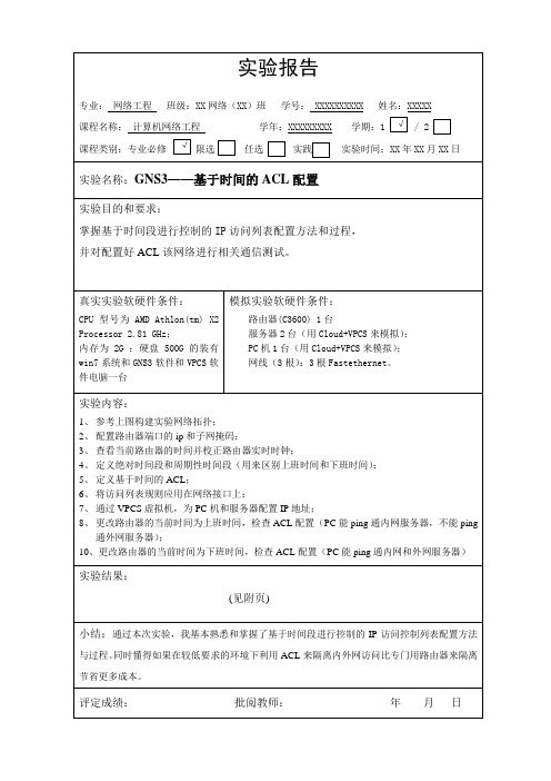
【网络拓扑结构图】【实验步骤】步骤1.(1)按照上图构建网络拓扑结构图(2)配置Router模块(3)配置各PC机的网络接口,右键点击PC1图标,选中“配置”→“NIO UDP”,进行如下图设置后,点击“添加”后再点击“OK”。
同理对serverA和serverB服务器进行配置,但各PC机和服务器间的本地端口号和远程端口号分别连续加1,使得各不相同。
同理对PC2进行配置。
(注意:各PC机间的本地端口和远程端口号应不同)(4)按照网络拓扑图完成设备连接步骤2 .标注端口及配置信息:步骤3. 配置路由器端口的ip和子网掩码;Router>enRouter#conf tRouter(config)#int f1/0Router(config-if)#ip add 1.1.1.1 255.255.255.0Router(config-if)#no shutRouter(config-if)#exitRouter(config)#int f2/0Router(config-if)#ip add 2.2.2.1 255.255.255.0Router(config-if)#no shutRouter(config-if)#exitRouter(config)#int f3/0Router(config-if)#ip add 3.3.3.1 255.255.255.0Router(config-if)#no shutRouter(config-if)#end步骤4.查看当前路由器的时间并校正路由器实时时钟;Router#show clockRouter#clock set 20:34:00 12 nov 2012Router#sh clock步骤5. 创建并定义Time-range接口Router>enRouter#conf tRouter(config)#time-range time1Router(config-time-range)#absolute start 8:00 1 jan 2006 end 17:00 30 dec 2012 Router(config-time-range)#periodic daily 8:00 to 17:00Router(config-time-range)#endRouter#sh time-range步骤6. 定义基于时间的ACLRouter#conf tRouter(config)#ip access-list extend net_list1Router(config-ext-nacl)#deny ip any host 3.3.3.2 time-range time1 Router(config-ext-nacl)#permit ip any anyRouter(config-ext-nacl)#endRouter#sh access-list步骤7. 将访问列表规则应用在网络接口上Router#conf tRouter(config)#int f1/0Router(config-if)#ip access-group net_list1 inRouter(config-if)#endRouter#sh ip int f1/0步骤8. 通过VPCS虚拟机,为PC机和服务器配置IP地址步骤9(1)更改路由器的当前时间为上班时间Router>enRouter#clock set 9:00:00 2 jan 2010Router#sh clock(2)检查PC与内网服务器间的通信由于设置的ACL中允许在任何时间访问内网,所以当内网主机访问内网时,通信正常。
标准访问控制列表实验

标准访问控制列表实验访问控制列表有两种:一种是标准的访问控制列表,另一种是扩展的访问控制列表。
访问控制列表(ACL)是应用在路由器接口的指令列表。
这些指令列表用来告诉路由器哪能些数据包可以收、哪能数据包需要拒绝。
至于数据包是被接收还是拒绝,可以由类似于源地址、目的地址、端口号等的特定指示条件来决定。
访问控制列表的应用:1、允许、拒绝数据包通过路由器2、允许、拒绝Telnet会话的建立3、没有设置访问列表时,所有的数据包都会在网络上传输4、基于数据包检测的特殊数据通讯应用标准访问控制列表应注意以下几点:1、检查源地址2、通常允许、拒绝的是完整的协议标准访问列表和扩展访问列表相比,标准的比扩展的简单。
下面我们来做一个关于标准访问控制列表的实验。
经过在路由上配置访问控制命令后,阻止R3 ping R2和R1,但是R3能ping通R4的端口s1/1和s1/2.实验的拓扑连接图如下:Router1 s1/2 <----> ip 192.168.1.2Router2 s1/2 <----> ip 192.168.2.2Router3 s1/2 <----> ip 192.168.3.2Router4 s1/1 <----> ip 192.168.1.1Router4 s1/2 <----> ip 192.168.2.1Router4 s1/3 <----> ip 192.168.3.1用到的模拟器版本为标准路由模拟器标准访问控制列表配置时候很简单,要用的设备也很简单,四台路由器,下面我们开始来做实验,第一步基本配置首先这是在路由器R4中的配置Route>enRoute#conf tRoute(config)#host R4R4(config)#int s1/1R4(config-if)#ip addr 192.168.1.1 255.255.255.0R4(config-if)#no shutR4(config-if)#exitR4(config)#int s1/2R4(config-if)#ip addr 192.168.2.1 255.255.255.0R4(config-if)#no shutR4(config-if)#exitR4(config)#int s1/3R4(config-if)#ip addr 192.168.3.1 255.255.255.0R4(config-if)#no shutR4(config-if)#exitR4(config)#router ripR4(config)#network 192.168.1.0R4(config)#network 192.168.2.0R4(config)#network 192.168.3.0R4(config)#exitR4#show ip route接下来配置R1,R2,R3,配置ip和启动RIP路由,配置如下:R1的IP是192.168.1.2R1(config)#router ripR1(config)#network 192.168.1.0R2的IP是192.168.2.2R2(config)#router ripR2(config)#network 192.168.2.0R3的IP是192.168.3.2R3(config)#router ripR3(config)#network 192.168.3.0Ok配置完成后我们测试一下,最后结果是R3 ping通R1和R2,第二步配置标准访问控制列表R4(config)#access-list 1 deny 192.168.3.0 0.0.0.255----------访问控制列表号+许可的IP网段+反掩码R4(config)#access-list 1 permit anyR4(config)#int s1/1R4(config-if)#ip access-group 1 out------------在接口上应用配置R4(config-if)#exitR4(config)#int s1/2R4(config-if)#ip access-group 1 outR4(config-if)#exitOk配置完成后我们测试一下,最后结果是R3 ping不通R1和R2,但是能R4的端口s1/1,s1/2标准访问控制列表的配置就这样的完成了…..。
实验三、标准访问控制列表和扩展访
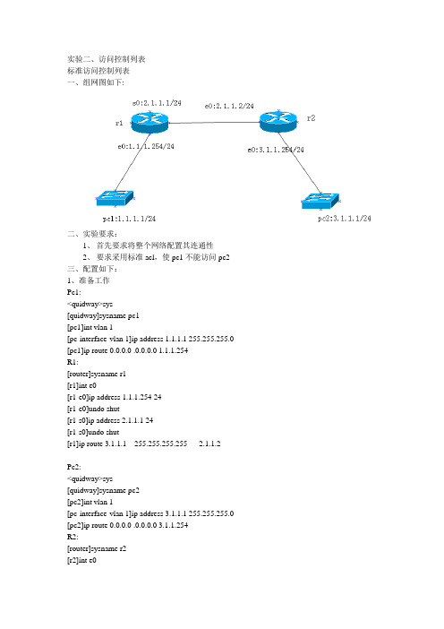
实验二、访问控制列表标准访问控制列表一、组网图如下:二、实验要求:1、首先要求将整个网络配置其连通性2、要求采用标准acl,使pc1不能访问pc2三、配置如下:1、准备工作Pc1:<quidway>sys[quidway]sysname pc1[pc1]int vlan 1[pc-interface-vlan 1]ip address 1.1.1.1 255.255.255.0 [pc1]ip route 0.0.0.0 .0.0.0.0 1.1.1.254R1:[router]sysname r1[r1]int e0[r1-e0]ip address 1.1.1.254 24[r1-e0]undo shut[r1-s0]ip address 2.1.1.1 24[r1-s0]undo shut[r1]ip route 3.1.1.1 255.255.255.255 2.1.1.2Pc2:<quidway>sys[quidway]sysname pc2[pc2]int vlan 1[pc-interface-vlan 1]ip address 3.1.1.1 255.255.255.0 [pc2]ip route 0.0.0.0 .0.0.0.0 3.1.1.254R2:[router]sysname r2[r2]int e0[r2-e0]ip address 3.1.1.254 24[r2-e0]undo shut[r2-s0]ip address 2.1.1.1 24[r2-s0]shut[r2-s0]undo shut[r2]ip route 1.1.1.0 255.255.255.0 2.1.1.1[pc1]ping 3.1.1.12、acl配置如下:[r1]acl 1 match auto[r1-acl-1]rule deny source 1.1.1.1 0.0.0.0[r1-acl-1]rule permit source any[r1]firewall enable[r1-e0]firewall packet 1 in[pc1]ping 3.1.1.1扩展访问控制列表一、组网图如上二、实验要求:1、首先要求将整个网络配置其连通性2、要求采用扩展acl,使pc1不能访问pc2,但pc2可以访问pc1三、配置如下:1、准备工作如上2、acl配置如下:[r1]acl 100 match auto[r1-acl-100]rule deny icmp source 1.1.1.1 0.0.0.0 destination 3.1.1.1 0.0.0.0 icmp-type echo log [rl-acl-100]rule permit ip source any destination any[r1]firewall enable[r1-e0]firewall pack 100 in[pc1]ping 3.1.1.1[pc2 ]ping 1.1.1.1。
编号标准ACL_计算机网络实践教程——基于GNS3网络模拟器(CISCO技术)_[共4页]
![编号标准ACL_计算机网络实践教程——基于GNS3网络模拟器(CISCO技术)_[共4页]](https://img.taocdn.com/s3/m/848fd9f4482fb4daa48d4ba9.png)
功能 ACL 编写基于编号,无法删除编号内特定某条语句 ACL 编写基于命名,可以修改、删除、增加特定某条语句 ACL 只能匹配源 IP 地址 ACL 能匹配源目 IP 地址、源目 Port、协议等
第 7 章 安全策略
7.1 编号标准 ACL
实验目的: 1.掌握编号标准 ACL 的基本编写。 2.理解编号标准 ACL 的基本特性。
实验拓扑:
实验随手记:
泛,例如,通过 ACL 可以实现局域网中不同部门之间的访问限制,如技术部和财务
部不能相互访问,其他部门可以相互访问;可以限制某个部门不能上网;可以限制特
定主机访问特定的服务器等。
2.ACL 分类
根据特征的不同,ACL 可以分为 4 种类型,如表 7-1 所示。
表 7-1 ACL 种类
ACL 编号 ACL 命名 ACL 标准 ACL 拓展 ACL
【ACL】 访问控制列表是网 络工程师接触的第 一种列表,用于实 现流量过滤。类似 功能有分发列表、 过滤列表等技术。
224
实验原理:
1.ACL 概述
ACL(Access-list,访问控制列表)是一种流量安全过滤工具,可以抓取特定流
量并执行丢弃和转发,是网络技术中众多策略表中最基础的一种。ACL 的使用非常广
GNS3模拟环境三层交换(vlan间互通+路由)+EtherChannel+rip路由+VTP+PVST+真实局域网

GNS3模拟环境下的三层交换(vlan间互通+路由)+EtherChannel+rip路由+VTP+PVST+真实局域网作者:wusam QQ1531036898,非诚勿扰时间:2012年4月5日星期三一、物理环境:二、网络拓扑环境:三、平台环境:GNS3v0.73+VPC3+SecureCRT5.1+TFTP使用GNS3搭建实验平台四朵云分别配置为:真实网卡、vpc2、vpc3、vpc4四、思路:1、R3为7200,交换机,通过云realLan和真实网卡桥接,然后和真实局域网连接,真实局域网为192.168.0.0/242、35501和35502为35系列插上交换模块的模拟三层交换机两台(要打开路由功能),sw1、sw2、sw3、sw4为2691插上交换模块的模拟交换机,此处要关闭路由功能。
三层交换机间配置以太通道,其他的交换机间连接配置trunk速链路。
交换机35502的f0/7关闭交换功能,配置端口地址。
35501为vtp server,其余全部为client。
Vlan1、2的根桥在35501,vlan3、4的根桥在35502。
3、DHCP由7200系列路由器模拟,配置DHCP功能,为了使真实局域网设备能ping 它,添加路由功能。
4、pc2~4由vpc3.0模拟,通过dhcp协议从DHCP服务器上获得地址SW1、SW2使用CISCO3640,PC1、PC2用VPC模拟,调试过程用SecureCRT5、为了配置方便,习惯用secureCRT工具来配置6、用TFTPserver来拷贝配置。
五、规划1、IP规划:35501 vlan10 :192.168.1.1 255.255.255.035501 vlan20 :192.168.2.1 255.255.255.035501 vlan30 :192.168.3.1 255.255.255.035501 vlan40 :192.168.4.1 255.255.255.035502 vlan10 :192.168.1.2 255.255.255.035502 vlan20 :192.168.2.2 255.255.255.035502 vlan30 :192.168.3.2 255.255.255.035502 vlan40 :192.168.4.2 255.255.255.035502 f0/7 192.168.5.1 255.255.255.0R8 f0/1 :192.168.5.2 255.255.255.0R8 f0/2 :192.168.0.201 255.255.255.0DHCP :192.168.1.3 255.255.255.0 192.168.1.1PC2:dhcpPC3:dhcpPC4:dhcp2,线缆规划:SW1的f1/1端口连接35501 f0/1端口,f1/2端口连接35502 f0/1端口,f1/3端口连接DHCP服务器,属于Vlan 1;SW2的f1/1端口连接35501 f0/2端口,f1/2端口连接35502 f0/2端口,f1/3端口连接PC1机,属于Vlan 2;SW3的f1/1端口连接35501 f0/3端口,f1/2端口连接35502 f0/3端口,f1/3端口连接PC2机,属于Vlan 3;SW4的f1/1端口连接35501 f0/4端口,f1/2端口连接35502 f0/4端口,f1/3端口连接PC3机,属于Vlan 4;35501 f0/5 端口连接35502 f0/5,35501 f0/6 端口连接35502 f0/635502 f0/7 端口连接 R8 f0/1, R8 f0/0端口连接云realLan3,VTP配置:VTP 的域名,VTP 的密码,VTP 的修剪,配置两台35501为VTP server 模式,配置其他交换机为client模式4,STP 配置:设置35501是Vlan1-Vlan2 的生成树根网桥设置35502是Vlan3-Vlan4 的生成树根网桥在接入层交换机上配置速端口和上行速链路5,三层交换机的配置:在其中一台交换机上划分Vlan; 在三层交换机上配置各个Vlan的IP地址,配置两台三层交换机之间的以太网通道(EthernetChannel)配置35502交换机的路由接口在三层交换机上配置RIP协议6,路由器的配置配置路由器接口的IP地址,配置路由器的RIP协议在R2上配置单臂路由7,配置SW5好了,规划完了,下面我们开始命令行配置吧:六步骤:1、启动GNS3网络平台2、启动SecureCRT3、配好各设备的端口,并分别进入各设备如图1、图2图1图24、配置vpc的ip地址、进入交换机,配置vlan、trunk、以太通道(备注:在GNS3中经常遇到说什么flash没有空间了,不能建立vlan,用exit时,叫你用abort,这样确实让人很烦,那么哥教你这么对付它:在特权模式下:#dir flash:#dir nvram:#copy vlan.dat nvram#erase flash:#squeeze flash:这样基本可以搞定!)35501配置:(不知肿么的,整块拷贝粘贴经常会出错,vlan protocol总是down,所以最好是一条一条敲命令,这样可以边观察、边互动)Enconf tho 35501 %ip routing %开启路由exit%配置vtp预vlan datvtp domai benet %设置vtp域名vtp pass 123 %设置vtp口令vtp pru %修剪vtp serv %设置vtp server模式%建立vlanvlan 10 name vlan10vlan 20 name vlan20vlan 30 name vlan30vlan 40 name vlan40exit%打开端口、设置中继conf tint ran f0/1 - 6sw m trno shutexit%配置pvstint ran f0/5 - 6chan 1 m onno shutexitspan vlan 10 root prispan vlan 20 root prispan vlan 30 root secspan vlan 40 root sec%配置vlan地址int vlan 10ip add 192.168.1.1 255.255.255.0no shutexitint vlan 20ip add 192.168.2.1 255.255.255.0no shutexitint vlan 30ip add 192.168.3.1 255.255.255.0no shutexitint vlan 40ip add 192.168.4.1 255.255.255.0no shutexit%配置路由conf trouter ripver 2net 192.168.1.0net 192.168.2.0net 192.168.3.0net 192.168.4.0exit%配置DHCP中继int vlan 10ip helper-add 192.168.1.3int vlan 20ip helper-add 192.168.1.3exit35502配置(和3501差不多,不再解释):enconf tho 35502ip routingexitvlan datvtp domai benetvtp pass 123vtp clivtp pruexitconf tint ran f0/1 - 6sw m trno shutexitint ran f0/5 - 6chan 1 m onno shutexitspan vlan 10 root secspan vlan 20 root secspan vlan 30 root prispan vlan 40 root priint vlan 10ip add 192.168.1.2 255.255.255.0 no shutexitint vlan 20ip add 192.168.2.2 255.255.255.0 no shutexitint vlan 30ip add 192.168.3.2 255.255.255.0 no shutexitint vlan 40ip add 192.168.4.2 255.255.255.0 no shutexitint f0/7no swip add 192.168.5.1 255.255.255.0 no shutexitrouter ripver 2net 192.168.1.0net 192.168.2.0net 192.168.3.0net 192.168.4.0net 192.168.5.0exit%配置DHCP中继int vlan 30ip helper-add 192.168.1.3int vlan 40ip helper-add 192.168.1.3exitsw1配置:%vtp设置enconf tho sw1ip routingexitvlan datvtp domai benetvtp pass 123vtp clivtp pruexit%配置端口conf tint f1/1sw m trno shutexitint f1/1sw m trno shutexitint f1/3sw acc vlan10spanning-tree portfast %端口速链路exitspanning-tree uplinkfast %上行速端口sw2、sw3、sw4配置类似dhcp server配置conf tint f0/0ip add 192.168.1.3 255.255.255.0no shutexitrouter ripver 2net 192.168.1.0exit%配置dhcpservice dhcp%从地址池中排除的地址(已被占用,不要再另行分配)ip dhcp excluded-address 192.168.1.1 192.168.1.3ip dhcp excluded-address 192.168.2.1 192.168.2.2ip dhcp excluded-address 192.168.3.1 192.168.3.2ip dhcp excluded-address 192.168.4.1 192.168.4.2ip dhcp ping timeout 1000 %设置ping的时间ip dhcp pool vlan10 %设置vlan1的地址池、等network 192.168.1.0 255.255.255.0default-router 192.168.1.1domain-name benetdns-server 192.168.1.3lease 5%与上边类似,不再解释ip dhcp pool vlan20network 192.168.2.0 255.255.255.0default-router 192.168.2.1domain-name benetip dhcp pool benetip dhcp pool vlan30network 192.168.3.0 255.255.255.0default-router 192.168.3.2domain-name benetip dhcp pool vlan40network 192.168.4.0 255.255.255.0default-router 192.168.4.2domain-name benet%设置连接端口f0/0的地址和路由interface FastEthernet0/0ip address 192.168.1.3 255.255.255.0duplex autospeed autorouter ripversion 2network 192.168.1.0路由器R8配置R8的配置:Conf tHo R8Int f0/1Ip add 192.168.5.2 255.255.255.0No shutInt f0/0Ip add 192.168.0.201 255.255.255.0No shutRouter ripVer 2Network 192.168.0.0Network 192.168.5.0ExitVPC设置及验证结果可以看见,vpc们都各取所需得到了自己的ip地址和网关。
标准的访问控制列表

实验标准的访问控制列表一、实验目的和要求• 理解什么是访问控制列表•了解访问控制列表的功能•掌握ACL工作原理及规则•掌握如何配置标准访问控制列表二、实验设备模拟软件:Cisco PacketTracer53_setup_no_tutorials设备:路由器两台,PC机若干,交叉线若干三、实验内容在路由器上配置标准的访问控制列表,以达到防止某网段的主机不能访问其他网段的主机的目的。
四、实验拓扑图图1 标准访问控制列表拓扑图五、背景描述你是一个公司的网络管理员,公司的经理部、财务部门和销售部门分属不同的3个网段,三部门之间用路由器进行信息传递,为了安全起见,公司领导要求销售部门不能对财务部门进行访问,但经理部可以对财务部门进行访问。
六、相关知识IP ACL(IP访问控制列表或IP访问列表)是实现对流经路由器或交换机的数据包根据一定的规则进行过滤,从而提高网络可管理性和安全性。
IP ACL分为两种:标准IP访问列表和扩展IP访问列表。
标准IP访问列表可以根据数据包的源IP地址定义规则,进行数据包的过滤。
扩展IP访问列表可以根据数据包的源IP、目的IP、源端口、目的端口、协议来定义规则,进行数据包的过滤。
IP ACL基于接口进行规则的应用,分为:入栈应用和出栈应用。
入栈应用是指由外部经该接口进行路由器的数据包进行过滤。
出栈应用是指路由器从该接口向外转发数据时进行数据包的过滤。
IP ACL的配置有两种方式:按照编号的访问列表,按照命名的访问列表。
标准IP访问列表编号范围是1~99、1300~1999,扩展IP访问列表编号范围是100~199、2000~2699。
七、实验步骤步骤1.画出实验拓扑结构图。
步骤2. 按实验拓扑图连接设备。
并对三台PC机进行IP设置。
步骤3.对路由器Router0进行基本配置(ip地址的配置和时钟配置)Router(config)#hostname Router0Router0(config)#interface fastEthernet 0/0Router0(config-if)#ip address 198.162.10.2 255.255.255.0Router0(config-if)#no shutdownRouter0(config-if)#exitRouter0(config)#interface fastEthernet 0/1Router0(config-if)#ip address 198.162.20.2 255.255.255.0Router0(config-if)#no shutdownRouter0(config-if)#exitRouter0(config)#interface serial 0/1/0Router0(config-if)#ip address 198.162.30.1 255.255.255.0Router0(config-if)#clock rate 64000Router0(config-if)#no shutdown步骤4.对路由器Router1进行基本配置Router(config)#hostname Router1Router1(config)#interface fastEthernet 0/0Router1(config-if)#ip address 198.162.40.1 255.255.255.0Router1(config-if)#no shutdownRouter1(config-if)#exitRouter1(config)#interface serial 0/1/0Router1(config-if)#ip address 198.162.30.2 255.255.255.0Router1(config-if)#no shutdown步骤5.在路由器Router0上开启RIP协议Router0(config)#router ripRouter0(config-router)#version 2Router0(config-router)#network 198.162.10.0Router0(config-router)#network 198.162.20.0Router0(config-router)#network 198.162.30.0Router0(config-router)#no auto-summary步骤6.在路由器Router1上开启RIP协议Router1(config)#router ripRouter1(config-router)#version 2Router1(config-router)#network 198.162.30.0Router1(config-router)#network 198.162.40.0Router1(config-router)#no auto-summary步骤7.查看路由器中的路由表,测试。
模拟器之GNS3完整安装及使用教程(关联Wireshark、xShell和VM)-收藏一篇就够

最新GNS3-2.2.7 模拟器完整安装及使用教程(关联Wireshark 、xShell6 和GNS3.VM.VMware.Workstation.2.2.7)- 收藏一篇就够别在碰壁现阶段学习经常使用的路由交换设备主要来自于思科、华为和华三三家,当然还有中兴、锐捷、神州数码等厂商,这三家的设备操作配置大致类似,却又不尽相同。
因为实体设备通常都非常昂贵,购买设备学习也是不现实的。
所以我们通常会使用各厂商提供的模拟器来学习。
华为的模拟器是eNSP ,华三的则是H3C Cloud Lib ,思科则是大名鼎鼎的GNS3 、Cisco Packet Tracer 、WEB-IOU 、EVE-NG 。
今天笔者拿GNS3-2.2.7 目前最新版本来安装。
、准备工具①GNS3-2.2.7-all-in-one.exe②GNS3.VM.VMware.Workstation.2.2.7.zip/ 对应版本的GNS3 虚拟机③Cisco IOU-ISO.zip (L2/L3 设备镜像)④IOS.rar (含从C1700 到C7200 的各种路由器bin 镜像)⑤Xshell6_wm.exe 或者SecureCRT⑥VMware-workstation-full-15.5.2-15785246.exe下载链接VMware-workstation-full-15.5.2-15785246链接:https:///s/1k3UKDc6NRbl8DtgCNxG4AA提取码:bolqGNS3链接:https:///s/1NDxi-l5i4YtP6nzzmpGebg提取码:te21二、GNS3 软件介绍GNS3 是一款具有图形化界面可以运行在多平台(包括Windows, Linux, and MacOS 等)的网络虚拟软件。
Cisco网络设备管理员或是想要通过CCNA ,CCNP ,CCIE等Cisco 认证考试的相关人士可以通过它来完成相关的实验模拟操作。
交换机 标准访问控制列表
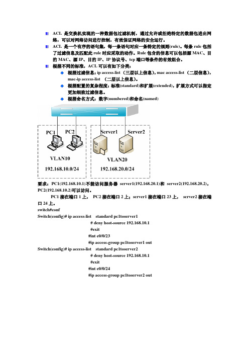
ACL 是交换机实现的一种数据包过滤机制,通过允许或拒绝特定的数据包进出网络,可以对网络访问进行控制,有效保证网络的安全运行。
ACL 是一个有序的语句集,每一条语句对应一条特定的规则(rule)。
每条rule包括了过滤信息及匹配此rule时应采取的动作。
Rule包含的信息可以包括源MAC、目的MAC、源IP、目的IP、IP协议号、tcp端口等条件的有效组合。
根据不同的标准,ACL可以有如下分类:根据过滤信息:ip access-list (三层以上信息),mac access-list (二层信息),mac-ip access-list (二层以上信息)。
根据配置的复杂程度:标准(standard)和扩展(extended),扩展方式可以指定更加细致过滤信息。
根据命名方式:数字(numbered)和命名(named)要求:PC1(192.168.10.1)不能访问服务器server1(192.168.20.1)和server2(192.168.20.2),PC2(192.168.10.2)可以访问。
PC1接在端口1上,PC2接在端口2上;server1接在端口23上,server2接在端口24上。
switch#confSwitch(config)# ip access-list standard pc1toserver1# deny host-source 192.168.10.1#exit#int e0/0/23#ip access-group pc1toserver1 outSwitch(config)# ip access-list standard pc1toserver2# deny host-source 192.168.10.1#exit#int e0/0/24#ip access-group pc1toserver2 out。
模拟器之GNS3完全安装及使用教学教程(关联Wireshark,xShell和VM)收藏一篇就够
最新GNS3-2.2.7模拟器完整安装及使用教程(关联Wireshark、xShell6和GNS3.VM.VMware.Workstation.2.2.7)-收藏一篇就够别在碰壁现阶段学习经常使用的路由交换设备主要来自于思科、华为和华三三家,当然还有中兴、锐捷、神州数码等厂商,这三家的设备操作配置大致类似,却又不尽相同。
因为实体设备通常都非常昂贵,购买设备学习也是不现实的。
所以我们通常会使用各厂商提供的模拟器来学习。
华为的模拟器是eNSP,华三的则是H3C Cloud Lib,思科则是大名鼎鼎的GNS3、Cisco Packet Tracer、WEB-IOU、EVE-NG。
今天笔者拿GNS3-2.2.7 目前最新版本来安装。
一、准备工具①GNS3-2.2.7-all-in-one.exe②GNS3.VM.VMware.Workstation.2.2.7.zip/对应版本的GNS3虚拟机③Cisco IOU-ISO.zip (L2/L3设备镜像)④IOS.rar (含从C1700 到C7200 的各种路由器bin 镜像)⑤Xshell6_wm.exe 或者SecureCRT⑥VMware-workstation-full-15.5.2-15785246.exe下载链接VMware-workstation-full-15.5.2-15785246链接:https:///s/1k3UKDc6NRbl8DtgCNxG4AA提取码:bolqGNS3链接:https:///s/1NDxi-l5i4YtP6nzzmpGebg提取码:te21二、GNS3软件介绍GNS3是一款具有图形化界面可以运行在多平台(包括Windows, Linux, and MacOS等)试的相关人士可以通过它来完成相关的实验模拟操作。
同时它也可以用于虚拟体验Cisco网三、软件安装3.1 安装GNS3-2.2.7-all-in-one.exe双击GNS3-2.2.7-all-in-one.exe(需要连网,安装需要依赖的组件,当然知道怎么安装组件的也可以不用连网)安装包含Wireshark点击I Agree点击Next选择Custom,注意Tools的选择注意:Tools:选择安装的位置安装过程中会弹出依赖的组件,点击Next点击I Agree点击Next点击Finish其他组件安装步骤一样输入邮箱点击Next选择No,下一步。
GNS3模拟一个中小型企业网络(有详细配置)

GNS3使用的是dinamips,没有交换机的IOS,本实验中,模拟二、三层交换机都是使用C3640+NM-16ESW模块。
注意:1、如果只是模拟二层交换机,一定要记住SW1(config)#no ip routing //关闭路由功能2、无法设置IP问题端口设置IP出现这个错误% IP addresses may not be configured on L2 links.需要从二层交换端口切换到三层交换端口SW2(config-if)#no switchport这里设置IP主要是连接路由器,但我遇到过用这个命令居然会提示命令不完整SW2(config-if)#no switchport% Incomplete command.我测试后,原来是我用的IOS版本低了,换成124版本的就没有这个问题了。
用到的IOS下载地址:c3640-ik9o3s-mz.124-13b 点击下载c7200-jk9o3s-mz.124-17 点击下载网络拓扑:设计的总公司还有两个出口:电信(R_Tele)和联通(R_Uni),一个驻外办事处(R_Part)。
电信(R_Tele),提供外网连接,实现nat转换和流量控制联通(R_Uni)实现与驻外办事处(R_Part)VPN连接。
汇聚层(L3Switch)实现DHCP。
详细配置:核心交换机Core_A:version 12.4service timestamps debug datetime msec service timestamps log datetime msec no service password-encryption!hostname Core_A!boot-start-markerboot-end-marker!!no aaa new-modelmemory-size iomem 5!!ip cefno ip domain lookupip domain name lab.localinterface Loopback0ip address 5.5.5.5 255.255.255.0!interface Port-channel1!interface FastEthernet0/0no switchportip address 172.16.59.1 255.255.255.0 !interface FastEthernet0/1no switchportip address 172.16.55.2 255.255.255.0 !interface FastEthernet0/2no switchportip address 172.16.58.2 255.255.255.0 !interface FastEthernet0/3no switchportip address 172.16.61.1 255.255.255.0 !interface FastEthernet0/4no switchportip address 172.16.63.1 255.255.255.0 !interface FastEthernet0/5no switchportip address 172.16.53.2 255.255.255.0 !interface FastEthernet0/6!interface FastEthernet0/7!interface FastEthernet0/8!interface FastEthernet0/9!interface FastEthernet0/10!interface FastEthernet0/11!interface FastEthernet0/12!interface FastEthernet0/13!interface FastEthernet0/14!interface FastEthernet0/15!interface Vlan1no ip addressshutdown!interface Vlan101ip address 172.16.200.1 255.255.255.0 !router ospf 100log-adjacency-changesnetwork 172.16.53.0 0.0.0.255 area 0 network 172.16.55.0 0.0.0.255 area 0 network 172.16.58.0 0.0.0.255 area 0 network 172.16.59.0 0.0.0.255 area 0 network 172.16.61.0 0.0.0.255 area 0 network 172.16.63.0 0.0.0.255 area 0 network 172.16.200.0 0.0.0.255 area 0 !no ip http serverno ip http secure-server!ip route 0.0.0.0 0.0.0.0 172.16.61.2ip route 0.0.0.0 0.0.0.0 172.16.63.2 115 !!control-plane!!line con 0exec-timeout 0 0privilege level 15logging synchronousline aux 0exec-timeout 0 0privilege level 15logging synchronousline vty 0 4login!!end核心交换机Core_B:version 12.4service timestamps debug datetime msec service timestamps log datetime msec no service password-encryption!hostname Core_B!boot-start-markerboot-end-marker!!no aaa new-modelmemory-size iomem 5!!ip cefno ip domain lookupip domain name lab.local!!!interface Loopback0ip address 4.4.4.4 255.255.255.0!interface FastEthernet0/0no switchportip address 172.16.59.2 255.255.255.0 !interface FastEthernet0/1no switchportip address 172.16.56.2 255.255.255.0 !interface FastEthernet0/2no switchportip address 172.16.57.2 255.255.255.0 !interface FastEthernet0/3no switchportip address 172.16.60.1 255.255.255.0 !interface FastEthernet0/4no switchportip address 172.16.64.1 255.255.255.0 !interface FastEthernet0/5no switchportip address 172.16.54.2 255.255.255.0 !interface FastEthernet0/6!interface FastEthernet0/7!interface FastEthernet0/8!interface FastEthernet0/9!interface FastEthernet0/10!interface FastEthernet0/11!interface FastEthernet0/12!interface FastEthernet0/13!interface FastEthernet0/14!interface FastEthernet0/15!interface Vlan1no ip addressshutdown!router ospf 100log-adjacency-changesnetwork 172.16.54.0 0.0.0.255 area 0 network 172.16.56.0 0.0.0.255 area 0 network 172.16.57.0 0.0.0.255 area 0 network 172.16.59.0 0.0.0.255 area 0 network 172.16.60.0 0.0.0.255 area 0 network 172.16.64.0 0.0.0.255 area 0 !router ospf 10log-adjacency-changes!no ip http serverno ip http secure-server!ip route 0.0.0.0 0.0.0.0 172.16.64.2ip route 0.0.0.0 0.0.0.0 172.16.60.2 115 !!control-plane!line con 0exec-timeout 0 0privilege level 15logging synchronousline aux 0exec-timeout 0 0privilege level 15logging synchronousline vty 0 4login!!End汇聚层配置:L3Switch_1:version 12.4service timestamps debug datetime msec service timestamps log datetime msec no service password-encryption!hostname L3Switch_1!boot-start-markerboot-end-marker!!no aaa new-modelmemory-size iomem 5!!ip cefno ip domain lookupip domain name lab.localno ip dhcp use vrf connected!ip dhcp pool DHCP_120network 172.16.12.0 255.255.255.0default-router 172.16.12.1dns-server 172.16.200.11!ip dhcp pool DHCP_160network 172.16.16.0 255.255.255.0default-router 172.16.16.1dns-server 172.16.200.11!!interface Loopback0ip address 1.1.1.1 255.255.255.0!interface FastEthernet0/0shutdown!interface FastEthernet0/1no switchportip address 172.16.55.1 255.255.255.0 !interface FastEthernet0/2no switchportip address 172.16.57.1 255.255.255.0 !interface FastEthernet0/3 switchport mode trunk!interface FastEthernet0/4 switchport mode trunk!interface FastEthernet0/5!interface FastEthernet0/6!interface FastEthernet0/7!interface FastEthernet0/8!interface FastEthernet0/9!interface FastEthernet0/10!interface FastEthernet0/11!interface FastEthernet0/12!interface FastEthernet0/13!interface FastEthernet0/14!interface FastEthernet0/15!interface Vlan1no ip addressshutdown!interface Vlan120ip address 172.16.12.1 255.255.255.0 !interface Vlan160ip address 172.16.16.1 255.255.255.0 !router ospf 100log-adjacency-changesnetwork 172.16.12.0 0.0.0.255 area 0 network 172.16.16.0 0.0.0.255 area 0 network 172.16.55.0 0.0.0.255 area 0 network 172.16.57.0 0.0.0.255 area 0 !no ip http serverno ip http secure-server!ip route 0.0.0.0 0.0.0.0 172.16.61.2!!control-plane!!dial-peer cor custom!line con 0exec-timeout 0 0privilege level 15logging synchronousline aux 0exec-timeout 0 0privilege level 15logging synchronousline vty 0 4login!!endL3Switch_2:version 12.4service timestamps debug datetime msec service timestamps log datetime msec no service password-encryption!hostname L3Switch_2!boot-start-markerboot-end-marker!!no aaa new-modelmemory-size iomem 5!!ip cefno ip domain lookupip domain name lab.localno ip dhcp use vrf connected!ip dhcp pool DHCP_10network 172.16.1.0 255.255.255.0default-router 172.16.1.1dns-server 172.16.200.11!ip dhcp pool DHCP_40network 172.16.4.0 255.255.255.0default-router 172.16.4.1dns-server 172.16.200.11!!interface Loopback0ip address 2.2.2.2 255.255.255.0!interface FastEthernet0/0!interface FastEthernet0/1no switchportip address 172.16.56.1 255.255.255.0 !interface FastEthernet0/2no switchportip address 172.16.58.1 255.255.255.0 !interface FastEthernet0/3 switchport mode trunk!interface FastEthernet0/4 switchport mode trunk!interface FastEthernet0/5!interface FastEthernet0/6!interface FastEthernet0/7!interface FastEthernet0/8!interface FastEthernet0/9!interface FastEthernet0/10!interface FastEthernet0/11!interface FastEthernet0/12!interface FastEthernet0/13!interface FastEthernet0/14!interface FastEthernet0/15!interface Vlan1no ip addressshutdown!interface Vlan10ip address 172.16.1.1 255.255.255.0 !interface Vlan40ip address 172.16.4.1 255.255.255.0!router ospf 100log-adjacency-changesnetwork 172.16.1.0 0.0.0.255 area 0 network 172.16.4.0 0.0.0.255 area 0 network 172.16.56.0 0.0.0.255 area 0 network 172.16.58.0 0.0.0.255 area 0 !no ip http serverno ip http secure-server!ip route 0.0.0.0 0.0.0.0 172.16.60.2!!control-plane!!line con 0exec-timeout 0 0privilege level 15logging synchronousline aux 0exec-timeout 0 0privilege level 15logging synchronousline vty 0 4login!!endL3Switch_3:version 12.4service timestamps debug datetime msec service timestamps log datetime msec no service password-encryption!hostname L3Switch_3!boot-start-markerboot-end-marker!!no aaa new-modelmemory-size iomem 5!!ip cefno ip domain lookupip domain name lab.localno ip dhcp use vrf connected!ip dhcp pool DHCP_80network 172.16.8.0 255.255.255.0default-router 172.16.8.1dns-server 172.16.200.11!ip dhcp pool DHCP_100network 172.16.10.0 255.255.255.0default-router 172.16.10.1dns-server 172.16.200.11!!interface Loopback0ip address 3.3.3.3 255.255.255.0!interface FastEthernet0/0!interface FastEthernet0/1no switchportip address 172.16.53.1 255.255.255.0 !interface FastEthernet0/2no switchportip address 172.16.54.1 255.255.255.0!interface FastEthernet0/3 switchport mode trunk!interface FastEthernet0/4 switchport mode trunk!interface FastEthernet0/5!interface FastEthernet0/6!interface FastEthernet0/7!interface FastEthernet0/8!interface FastEthernet0/9!interface FastEthernet0/10!interface FastEthernet0/11!interface FastEthernet0/12!interface FastEthernet0/13!interface FastEthernet0/14!interface FastEthernet0/15!interface Vlan1no ip addressshutdown!interface Vlan80ip address 172.16.8.1 255.255.255.0 !interface Vlan100ip address 172.16.10.1 255.255.255.0 !router ospf 100log-adjacency-changesnetwork 172.16.8.0 0.0.0.255 area 0 network 172.16.10.0 0.0.0.255 area 0 network 172.16.53.0 0.0.0.255 area 0network 172.16.54.0 0.0.0.255 area 0 !no ip http serverno ip http secure-server!ip route 0.0.0.0 0.0.0.0 172.16.61.2!!control-plane!!line con 0exec-timeout 0 0privilege level 15logging synchronousline aux 0exec-timeout 0 0privilege level 15logging synchronousline vty 0 4login!!end接入层配置:L2Switch_1:version 12.4service timestamps debug datetime msec service timestamps log datetime msec no service password-encryption!hostname L2Switch_1!boot-start-markerboot-end-marker!!no aaa new-modelmemory-size iomem 5no ip routing!!no ip cefno ip domain lookupip domain name lab.local!!!interface FastEthernet0/0switchport mode trunk!interface FastEthernet0/1switchport access vlan 160!interface FastEthernet0/2switchport access vlan 160!interface FastEthernet0/3switchport access vlan 160!interface FastEthernet0/4switchport access vlan 160!interface FastEthernet0/5switchport access vlan 160!interface FastEthernet0/6switchport access vlan 160 !interface FastEthernet0/7 switchport access vlan 160 !interface FastEthernet0/8 switchport access vlan 160 !interface FastEthernet0/9 switchport access vlan 160 !interface FastEthernet0/10 switchport access vlan 160 !interface FastEthernet0/11 switchport access vlan 160 !interface FastEthernet0/12 switchport access vlan 160 !interface FastEthernet0/13 switchport access vlan 160 !interface FastEthernet0/14 switchport access vlan 160 !interface FastEthernet0/15 switchport access vlan 160 !interface Vlan1no ip addressno ip route-cache shutdown!interface Vlan160no ip address!no ip http serverno ip http secure-server!!!!control-plane!!line con 0exec-timeout 0 0 privilege level 15 logging synchronous line aux 0exec-timeout 0 0 privilege level 15 logging synchronous line vty 0 4login!!endL2Switch_2:version 12.4service timestamps debug datetime msec service timestamps log datetime msec no service password-encryption!hostname L2Switch_2!boot-start-markerboot-end-marker!!no aaa new-modelmemory-size iomem 5no ip routing!!no ip cefno ip domain lookupip domain name lab.local!interface FastEthernet0/0switchport mode trunk!interface FastEthernet0/1switchport access vlan 120!interface FastEthernet0/2switchport access vlan 120!interface FastEthernet0/3switchport access vlan 120!interface FastEthernet0/4switchport access vlan 120!interface FastEthernet0/5switchport access vlan 120!interface FastEthernet0/6switchport access vlan 120!interface FastEthernet0/7switchport access vlan 120!interface FastEthernet0/8 switchport access vlan 120 !interface FastEthernet0/9 switchport access vlan 120 !interface FastEthernet0/10 switchport access vlan 120 !interface FastEthernet0/11 switchport access vlan 120 !interface FastEthernet0/12 switchport access vlan 120 !interface FastEthernet0/13 switchport access vlan 120 !interface FastEthernet0/14 switchport access vlan 120 !interface FastEthernet0/15 switchport access vlan 120 !interface Vlan1no ip addressno ip route-cache shutdown!interface Vlan120no ip addressno ip route-cache!no ip http serverno ip http secure-server!!control-plane!line con 0exec-timeout 0 0 privilege level 15 logging synchronousline aux 0exec-timeout 0 0 privilege level 15 logging synchronous line vty 0 4login!!endL2Switch_3:!version 12.4service timestamps debug datetime msec service timestamps log datetime msec no service password-encryption!hostname L2Switch_3!boot-start-markerboot-end-marker!no aaa new-modelmemory-size iomem 5!ip cefno ip domain lookupip domain name lab.local!interface FastEthernet0/0switchport mode trunk!interface FastEthernet0/1switchport access vlan 40!interface FastEthernet0/2switchport access vlan 40!interface FastEthernet0/3switchport access vlan 40!interface FastEthernet0/4switchport access vlan 40!interface FastEthernet0/5switchport access vlan 40!interface FastEthernet0/6switchport access vlan 40!interface FastEthernet0/7switchport access vlan 40!interface FastEthernet0/8switchport access vlan 40 !interface FastEthernet0/9 switchport access vlan 40 !interface FastEthernet0/10 switchport access vlan 40 !interface FastEthernet0/11 switchport access vlan 40 !interface FastEthernet0/12 switchport access vlan 40 !interface FastEthernet0/13 switchport access vlan 40 !interface FastEthernet0/14 switchport access vlan 40 !interface FastEthernet0/15 switchport access vlan 40 !interface Vlan1no ip address!no ip http serverno ip http secure-server!control-plane!line con 0exec-timeout 0 0 privilege level 15 logging synchronous line aux 0exec-timeout 0 0 privilege level 15 logging synchronous line vty 0 4loginendL2Switch_4:version 12.4service timestamps debug datetime msec service timestamps log datetime msec no service password-encryption!hostname L2Switch_4!boot-start-markerboot-end-marker!!no aaa new-modelmemory-size iomem 5!!ip cefno ip domain lookupip domain name lab.local!interface FastEthernet0/0switchport mode trunk!interface FastEthernet0/1switchport access vlan 10!interface FastEthernet0/2switchport access vlan 10!interface FastEthernet0/3switchport access vlan 10!interface FastEthernet0/4switchport access vlan 10!interface FastEthernet0/5switchport access vlan 10!interface FastEthernet0/6switchport access vlan 10!interface FastEthernet0/7switchport access vlan 10!interface FastEthernet0/8 switchport access vlan 10 !interface FastEthernet0/9 switchport access vlan 10 !interface FastEthernet0/10 switchport access vlan 10 !interface FastEthernet0/11 switchport access vlan 10 !interface FastEthernet0/12 switchport access vlan 10 !interface FastEthernet0/13 switchport access vlan 10 !interface FastEthernet0/14 switchport access vlan 10 !interface FastEthernet0/15 switchport access vlan 10 !interface Vlan1no ip address!no ip http serverno ip http secure-server!control-plane!line con 0exec-timeout 0 0 privilege level 15 logging synchronous line aux 0exec-timeout 0 0 privilege level 15 logging synchronous line vty 0 4loginendL2Switch_5:version 12.4service timestamps debug datetime msec service timestamps log datetime msec no service password-encryption!hostname L2Switch_5!boot-start-markerboot-end-marker!no aaa new-modelmemory-size iomem 5no ip routing!no ip cefno ip domain lookupip domain name lab.local!interface FastEthernet0/0switchport mode trunk!interface FastEthernet0/1switchport access vlan 80!interface FastEthernet0/2switchport access vlan 80!interface FastEthernet0/3switchport access vlan 80!interface FastEthernet0/4switchport access vlan 80!interface FastEthernet0/5switchport access vlan 80!interface FastEthernet0/6switchport access vlan 80!interface FastEthernet0/7switchport access vlan 80!interface FastEthernet0/8 switchport access vlan 80 !interface FastEthernet0/9 switchport access vlan 80 !interface FastEthernet0/10 switchport access vlan 80 !interface FastEthernet0/11 switchport access vlan 80 !interface FastEthernet0/12 switchport access vlan 80 !interface FastEthernet0/13 switchport access vlan 80 !interface FastEthernet0/14 switchport access vlan 80 !interface FastEthernet0/15 switchport access vlan 80 !interface Vlan1no ip addressno ip route-cache!no ip http serverno ip http secure-server!control-plane!line con 0exec-timeout 0 0 privilege level 15 logging synchronous line aux 0exec-timeout 0 0 privilege level 15 logging synchronous line vty 0 4loginEndL2Switch_6:version 12.4service timestamps debug datetime msec service timestamps log datetime msec no service password-encryption!hostname L2Switch_6!boot-start-markerboot-end-marker!no aaa new-modelmemory-size iomem 5no ip routing!no ip cefno ip domain lookupip domain name lab.local!interface FastEthernet0/0switchport mode trunk!interface FastEthernet0/1switchport access vlan 100!interface FastEthernet0/2switchport access vlan 100!interface FastEthernet0/3switchport access vlan 100!interface FastEthernet0/4switchport access vlan 100!interface FastEthernet0/5switchport access vlan 100!interface FastEthernet0/6switchport access vlan 100!interface FastEthernet0/7switchport access vlan 100!interface FastEthernet0/8switchport access vlan 100 !interface FastEthernet0/9 switchport access vlan 100 !interface FastEthernet0/10 switchport access vlan 100 !interface FastEthernet0/11 switchport access vlan 100 !interface FastEthernet0/12 switchport access vlan 100 !interface FastEthernet0/13 switchport access vlan 100 !interface FastEthernet0/14 switchport access vlan 100 !interface FastEthernet0/15 switchport access vlan 100 !interface Vlan1no ip addressno ip route-cache!no ip http serverno ip http secure-server!control-plane!line con 0exec-timeout 0 0 privilege level 15 logging synchronousline aux 0exec-timeout 0 0 privilege level 15 logging synchronousline vty 0 4loginEndR_Telecon:说明:电信出口,提供外网连接,实现nat转换和流量控制upgrade fpd autoversion 12.4service timestamps debug datetime msecservice timestamps log datetime msecno service password-encryption!hostname R_Telecon!boot-start-markerboot-end-marker!logging message-counter syslog!no aaa new-modelip source-routeip cef!no ip domain lookupip domain name lab.localno ipv6 cef!multilink bundle-name authenticated!memory-size iomem 0archivelog confighidekeys!class-map match-all 1match access-group 11class-map match-all 2match access-group 22class-map match-all 3match access-group 33!policy-map FlowControlclass 1bandwidth 2000class 2bandwidth 4000class 3bandwidth 8000interface FastEthernet0/0ip address 172.16.61.2 255.255.255.0ip nat insideip virtual-reassemblyduplex autospeed auto!interface FastEthernet0/1ip address 172.16.64.2 255.255.255.0ip nat insideip virtual-reassemblyduplex autospeed auto!interface FastEthernet1/0ip address 192.168.137.2 255.255.255.0ip nat outsideip virtual-reassemblyduplex half!ip forward-protocol ndip route 0.0.0.0 0.0.0.0 192.168.137.1ip route 172.16.0.0 255.255.0.0 172.16.61.1ip route 172.16.0.0 255.255.0.0 172.16.64.1 115no ip http serverno ip http secure-server!ip nat pool Out_Pool 192.168.137.5 192.168.137.10 netmask 255.255.255.0 ip nat inside source list 100 pool Out_Pool overload!access-list 11 permit 172.16.1.0 0.0.0.255access-list 22 permit 172.16.4.0 0.0.0.255access-list 33 permit 172.16.12.0 0.0.0.255access-list 100 permit ip 172.16.0.0 0.0.255.255 any!control-plane!mgcp fax t38 ecm!gatekeepershutdown!!line con 0exec-timeout 0 0 privilege level 15 logging synchronous stopbits 1line aux 0exec-timeout 0 0 privilege level 15 logging synchronous stopbits 1line vty 0 4login!endR_Unicom:%说明:联通出口路由,实现与其他办事处(R_Part)的VPN连接以及流量控制upgrade fpd autoversion 12.4service timestamps debug datetime msecservice timestamps log datetime msecno service password-encryption!hostname R_Unicom!boot-start-markerboot-end-marker!logging message-counter syslog!no aaa new-modelip source-routeip cef!no ip domain lookupip domain name lab.localno ipv6 cef!multilink bundle-name authenticated!memory-size iomem 0archivelog confighidekeys!!crypto isakmp policy 10hash md5authentication pre-sharecrypto isakmp key 1002 address 111.1.1.1!!crypto ipsec transform-set Tran esp-des!crypto map Map 100 ipsec-isakmpset peer 111.1.1.1set transform-set Tranmatch address 111!!!!class-map match-all 1match access-group 11class-map match-all 2match access-group 22class-map match-all 3match access-group 33!!policy-map FlowControlclass 1bandwidth 2000class 2bandwidth 4000class 3bandwidth 8000!!!!!interface Tunnel0ip address 172.16.70.1 255.255.255.0 tunnel source Serial1/0tunnel destination 111.1.1.1!interface FastEthernet0/0ip address 172.16.60.2 255.255.255.0 ip nat insideip virtual-reassemblyduplex autospeed auto!interface FastEthernet0/1ip address 172.16.63.2 255.255.255.0 duplex autospeed auto!interface Serial1/0ip address 222.2.2.2 255.255.255.0ip nat outsideip virtual-reassemblyserial restart-delay 0crypto map Map!interface Serial1/1no ip addressshutdownserial restart-delay 0!interface Serial1/2no ip addressshutdownserial restart-delay 0!interface Serial1/3no ip addressshutdownserial restart-delay 0!interface Serial1/4no ip addressshutdownserial restart-delay 0!interface Serial1/5no ip addressshutdownserial restart-delay 0!interface Serial1/6no ip addressshutdownserial restart-delay 0!interface Serial1/7no ip addressshutdownserial restart-delay 0!router ospf 1router-id 6.6.6.6log-adjacency-changesnetwork 172.16.60.0 0.0.0.255 area 0network 172.16.70.0 0.0.0.255 area 0!ip forward-protocol ndip route 0.0.0.0 0.0.0.0 222.2.2.1ip route 172.16.0.0 255.255.0.0 172.16.60.1no ip http serverno ip http secure-server!!ip nat pool Out_pool 222.2.2.5 222.2.2.10 netmask 255.255.255.0 ip nat inside source list 100 pool Out_pool overload!access-list 11 permit 172.16.1.0 0.0.0.255access-list 22 permit 172.16.4.0 0.0.0.255access-list 33 permit 172.16.12.0 0.0.0.255access-list 100 permit ip 172.16.0.0 0.0.255.255 anyaccess-list 111 permit gre host 222.2.2.2 host 111.1.1.1!!control-plane!!!mgcp fax t38 ecm!gatekeepershutdown!!line con 0exec-timeout 0 0privilege level 15logging synchronousstopbits 1line aux 0exec-timeout 0 0privilege level 15logging synchronousstopbits 1line vty 0 4login!endR_Part:%说明:驻外办事路由器,实现与总公司VPN连接。
标准访问控制列表配置实训

标准访问控制列表配置实训一、实验目的本实训旨在让学生掌握标准访问控制列表的配置方法,理解其工作原理,并能够根据实际需求进行正确的配置。
二、实验设备1. 路由器或交换机2. 计算机或笔记本3. 网络线4. 模拟软件(如GNS3)三、实验步骤与配置示例步骤1:设备连接与基本配置1. 在模拟软件GNS3中,拖拽一个路由器图标并连接到两台计算机,分别命名为Router1和Router2。
2. 启动Router1和Router2,并进入命令行界面。
3. 对两台设备进行基本配置,包括设置主机名、IP地址等。
示例:Router1:Router>enableRouter#configure terminalRouter(config)#hostname Router1Router1(config)#ip dhcp pool pool1Router1(config)#ip dhcp pool pool2Router1(config)#interface GigabitEthernet0/0Router1(config-if)#ip address 192.168.1.1 255.255.255.0Router1(config-if)#no shutdownRouter1(config-if)#exitRouter1(config)#interface GigabitEthernet0/1Router1(config-if)#ip address 192.168.2.1 255.255.255.0Router1(config-if)#no shutdownRouter1(config-if)#exitRouter1(config)#ip route 0.0.0.0 0.0.0.0 192.168.2.254步骤2:配置标准访问控制列表(ACL)1. 在Router1上创建一个标准访问控制列表(ACL),允许源IP为192.168.1.0/24的数据包访问目标IP为192.168.2.0/24的数据包。
GNS3完全使用手册
切记,相关文件夹最好全部中文,要不会提示“can’t set up hyversion port 7200类似错误”GNS3 完全使用手册软件介绍:Cisco网络模拟器----GNS3 v0.6.1 all-in-one终端仿真程序-------SecureCRT V6.2.0.195GNS3 简介:GNS3是基于Dynamips的图形界面模拟器,可以为Cisco网络工程师、管理员、Cisco 证书考生提供近乎完美的实验环境。
GNS3 v0.6.1 all-in-one软件包包含了WinPCAP 4.0.2、Dynamips 0.2.8 RC2、Pemuwrapper 0.2.3、GNS3 0.6.1(注:不包含IOS)。
该软件提供了图形化的界面,用户可以之方便地搭建各种拓扑图,而且安装调试更加方便!GNS3项目是免费开源的自由的程序,适用于多种操作系统,包括Windows,Linux和MacOS X。
GNS3 v0.6.1现在发布,包括以下新功能和改善......用户可修改工作区大小;可以绘制矩形和椭圆;自动为接口名称创建标签;多重联线(不重叠);快照功能;Windows平台版提供了物理网卡列表直接绑定功能;所有工作区可以导出为图片(JPEG,PNG...);拓扑摘要面板增加“展开所有”和“缩小所有”功能(由beduev贡献);注解、矩形和椭圆可以旋转;在Windows平台下,用户可以通过命令行加载指定的gns3.ini配置文件,例如:gns3.exe --configdir新增塞尔维亚语言此外,本版本修改了之前的很多bug。
至于虚拟PC模拟功能,不能在这个版本囊括。
作者表示已经找到了在Dynamips直接整合的办法,请耐心等待。
安装过程:安装过程相当简单,直接“NEXT”就可以了,如下图所示:到此,GNS3的安装已全部完成。
设置向导:安装完成后,打开GNS3软件,第一次打开GNS3,会出现设置向导,设置具体步骤如下:1、设置“Dynamips”:在设置向导界面中,选择“STEP1”,如下图所示:此时,进入到“Perferences”设置,习惯用中文的,可在“General”----“Language”处,选上“简体中文(cn)”。
GNS3模拟环境下的vlan+EtherChannel+rip 路由+真实局域网

GNS3模拟环境下的vlan+EtherChannel+rip路由+真实局域网作者:wusam时间:2012年4月4日星期三物理环境:网络拓扑环境:平台环境:GNS3v0.73+VPC3+SecureCRT5.1使用GNS3搭建实验平台三朵云分别配置为:真实网卡、vpc1、vpc2思路:R1为7200,SW1、SW2使用CISCO3640,PC1、PC2用VPC模拟,调试过程用SecureCRT IP地址规划:由于是实验 所以使用私网IP地址192.168.10.0/24和192.168.20.0/24分别为VLAN10和VLAN20分配地址段PC1 IP:192.168.10.1/24PC2 IP:192.168.20.1/24路由器R1F0/0子接口F0/0.10 IP:192.168.10.254/24F0/0.20 IP:192.168.20.254/24F0/1 IP:192.168. 0.201/24SW1与SW2是使用CISCO3640+NM-16ESW模块模拟交换机。
SW1、SW2之间使用(EtherChannel)以太通道做负载均衡两台交换机使用VTP快速部署VLANSW1为SERVER,SW2为CLIENT在两台交换机上创建VLAN10、VLAN20由于是路由器模拟交换机,所以创建VLAN的方式是在VLAN数据库中创建VLAN 以及VTP 模式步骤:1、启动GNS3网络平台2、启动SecureCRT3、配好各设备的端口,并分别进入各设备如图1、图2图1图24、配置vpc的ip地址、进入交换机,配置vlan、trunk、以太通道(备注:在GNS3中经常遇到说什么flash没有空间了,不能建立vlan,用exit时,叫你用abort,这样确实让人很烦,那么哥教你这么对付它:在特权模式下:#dir flash:#dir nvram:#copy vlan.dat nvram#erase flash:#squeeze flash:这样基本可以搞定!)使用单臂路由实现VLAN 间路由。
Cisco模拟器GNS3使用手册(可编辑修改word版)

1. GNS3 简介: Cisco 模拟器 GNS3 使用手册GNS3 是一款能够运行在多平台下具有图形化界面的 Cisco 模拟器,其中 Dynamips 是其核心程序,GNS3 能够在虚拟机上运行 Cisco IOS 来进行模拟各种 Cisco 设备。
2. GNS3 使用介绍:点击桌面上的“GNS3”图标来启动 GNS3 程序,启动后界面如下所示:启动完成之后,可以输入一个名称,来对新工程进行命名,当然,也可以点击“Cannel ” 按钮暂时不对该工程命名,拓扑图等配置建立完成之后也可以再进行命名保存。
可以看出,在菜单栏中有四个可选选项“文件(F )”,“编辑(E )”,“查看(V )”,“帮助(H )”。
(1) 文件(F )新建工程(N ):该选项用来新建另外一个工程。
打开(O ):该选项用来打开一个已存的工程,通常都是之前所保存的 NET 为后缀的文件。
保存(S ):该选项用来保存所建的工程。
另存为(S ):该选项用来将工程另存为另外一个工程名。
输出(E):该选项用来将工程中所建的拓扑图以png 的图片格式进行保存。
退出(Q):该选项用来退出GNS3。
(2)编辑(E)选择所有(A):选择该选项则会选中拓扑图中所建的所有设备。
取消选择(N):该选项会取消拓扑图中所选择的设备。
IOS 和Hypervisors:该选项主要是配置GNS3 中所定义的各种Cisco IOS。
如图显示出所定义的两种路由器7200 和3640。
如需要添加另外的IOS,则只需要选择好相应的IOS 镜像文件,在“平台”和“型号”下拉框中选择相对应的选项,然后定义内存值,一般设置为96MB,设置完成之后进行点击“保存”按钮即可完成。
图标管理(S):在这里可以自定义一些节点。
首选项(P):这里对GNS3 进行各种参数的配置。
“一般”标签页面:该页面主要是GNS3 的一些基本设置,如语言和界面规划等信息。
语言选项:可以对软件的显示语言进行选择设置。
