【US10489311B1】管理对本地和重定向USB设备的WebUSB支持【专利】
Windows 7 安装功能隐私声明
收集的信息用于帮助下载相关的设备信息。发送的任何信息都不会用于确定您的身份或与您联系。
选项与控制
如果您在 Windows 7 安装期间选择推荐设置,则打开“设备信息检索”。您可以通过转至“控制面板”中的“设 备和打印机”,右键单击计算机图标,然后单击“设备安装设置”,关闭此功能。选择“否,让我选择要进行 的操作”,然后清除“使用增强的图标替换通用设备图标”复选框。
Microsoft 错误报告服务
此功能的用途
Microsoft 错误报告服务可帮助 Microsoft 和 Microsoft 合作伙伴诊断您所用软件中的问题并提供相应的解 决方案。并非所有问题都有解决方案,但是当解决方案可用时,会将这些解决方案作为解决您报告的问题的步 骤提供,或者将这些解决方案作为要安装的更新提供。为了避免问题并使软件更加可靠,在服务包和该软件的 未来版本中也包含一些解决方案。
Microsoft 在针对您的个人计算需求为您提供高性能、功能强大且便利的产品的同时,承诺保护您的隐私。本 隐私声明对安装和设置 Windows 7(“安装功能”)时,您可以决定的一些影响隐私的功能的数据收集和使用 惯例进行了说明:激活、设备信息检索、Microsoft 错误报告服务、SmartScreen 筛选、更新服务、Windows 客 户体验改善计划、Windows Defender 和 Windows 帮助。
Microsoft 错误报告服务还提供“安装修复”,一种可以在 Windows 安装过程出现问题时运行的错误报告服务。
收集、处理或传输的信息
许多 Microsoft 软件程序(其中包括 Windows 7)设计为与该报告服务一起使用。如果在其中一个软件程序中 出现问题,系统将询问您是否要报告该问题。如果使用 Windows 操作系统托管虚拟机,则由 Windows 操作系 统为 Microsoft 错误报告服务生成的报告可能包含有关虚拟机的信息。
柔性检查作用域套件-USB 产品说明书
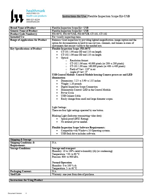
lInstructions for Use: Flexible Inspection Scope Kit-USB Brand Name of ProductFlexible Inspection Scope Kit - USB Generic Name of ProductFlexible Inspection Scope Kit - USB Product Code Number(s)FIS-007U, FIS-007USK, FIS-007UB, CT-101, CT-102Intended UseFor visually inspecting items.Range of Applications for ProductEnhance visual inspection by providing lighted magnification, image capture and the option for documentation in hard-to-see crevices, channels, and lumens in areas of instruments that are not visible to the unaided eye.Key Specifications of Product Flexible Inspection Scope- FIS-007U∙CT-101 1.90 mm OD and 110 cm length∙CT-102 1.06 mm OD and 110 cm length∙Opticalo Resolution format:o CT-102 1.06 mm: 40,000 pixels (or 200- x 200 pixels)o CT-101 1.90 mm: 160,000 pixels (or 400- x 400 pixels)o Field of View: 120° in airo Angle of view: 0°USB Control Module: Control Module housing Camera processor and LEDillumination:∙Dimensions: 5.25- x 3.90- x 1.85 inches∙Weight: 1.20 pounds ∙Digital Inspection Scope Connection∙Illumination Control- LED in the Control Module∙Power Cycle∙USB Camera Cable∙Easily change from small and large diameter scopes.Light Settings:There are four light settings operated by one button.Blinking Light (Indicates transmitting video data):∙Splash proof (IPX5 Rating)∙No external power needed.Flexible Inspection Scope Software Requirements:∙Compatible with Windows 10 Operating systems.∙USB flash drive includes software.Unpacking Flexible Inspection Scope:Carefully inspect for shipping damage. If there is any damage contact the shipping carrier and Heatlhmarkcustomer service 800-521-6224 immediately.USB Control Module: (Fig. 1).1.Digital Inspection Scope Connection 2.Illumination Control 3.Power Cycle B (Type C) on the right side of the boxFigure 1Flexible Inspection Scope™: (Fig. 2).∙CT-101 1.90 mm O.D. and 110 cm length ∙CT-102 1.06 mm O.D. and 110 cm lengthLarge1.90 mmSmall 1.06 mmFigure 2Flexible Inspection Scope™ Features3214Light/Illumination Settings: (Fig. 3).∙Five (5) light settingso Light on control indicats setting levelo Fifth setting is OFF∙Press light button to advance to next setting.∙Fifth setting turns the light OFF.Figure 3Power Cycle ButtonPress button to RESET camera (Fig. 4).Figure 41.Flexible Inspection Scope™ Plug (Fig. 5).Contains camera video connection as well as LED Light for illumination.1Figure 52.Flexible Working Length (Fig. 6).The portion of the Flexible Inspection Scope™ that is inserted into an item during visual inspection.The measuring scale markings on the Flexible Working Length are in centimeters (accuracy = ± 0.5 cm)2Figure 63.Distal Camera (Fig. 7).Distal portion of Flexible Inspection Scope™ that contains the camera lens3Figure 7SOFTWARE INSTALLATION:Note: This section is done only once when connecting the scope to the computer for the first time.∙System Requirements: MS Windows 10∙Install the Flexible Inspection Scope™ Software from the USB flash drive on a computer.Note: If you have any IT policies that may block this installation, please contact your IT team to give access to Healthmark scope viewer to install.1. Insert the USB Flash drive into your computer, and double click on the Healthmark Scope Viewer installer package to begin installation.2. The “Welcome to the Healthmark Scope Viewer Setup Wizard” screen pops up. Click on Next.3. Select the first tab Typical or setup type of your choice, click Next.4. Click Install and wait for installation to complete.5. Click Finish.STARTING SOFTWARE & CONNECTING SCOPE TO PC:(Fig 8).1.Open the Windows PC viewer software.2.Connect the Control Module to PC using USB Cable.3.Plug the Flexible Inspection Scope into the Control Module.4.In the viewer software, click Settings and Select USB Video Device, click on the desiredresolution, select the preferred Video Output Format, and then Click OK.5.Press the Power Cycle Button.Figure 86.Now you can start using the scope.Verifing OperationFollowing the steps listed below will ensure the proper use and performance of the Flexible Inspection Scope™. The Flexile Inspection Scope™ can be checked for normal operation by connecting it as described in the Startup section of this IFU.Normal operation includes:∙An image appearing on your computer monitor or HDMI Monitor.∙ A blinking light on Control Module near the Power Cycle button that indicates the image feed is transmitting.∙White light emitting from the distal end of the Digital Inspection Scope.∙An LED light on the control module top panel that indicates the light intensity of the device. Using SoftwareHealthmark Scope Viewer Software (Fig. 9).1.Capture button: Captures a Reference Image and saves it to the Reference Image folder.2.Main Image Window: Displays the image from the camera.3.Reference Image Window: Displays a reference image.4.Clear Button: Removes the image from the Reference image window.5.Open Reference Image button: Allows selection of a reference image from the Reference Imagefolder.6.Settings Button: Click to select the video camera and resolution settings.7.File Location Button: Click to change location where captured images are being saved.8.File Location Window: Shows the file path where captured images are being saved currently.9.Capture Image Button: Captures images and adds them to the File Location selected by the user(as shown in the File Location Window).10.Capture Video button: Click to record video. Click again to stop recording video.11.File Prefix: Type in text that you would like included in the file name of Captured Images.Figure 9Selecting Video Device or CameraFollow the directions below to select the video device or camera used to capture images using the Flexible Inspection Scope™ Viewer Software. (Fig. 10).1.Click Settings button in the lower left of the Scope Viewer software to display a list of videodevices or cameras being detected by your computer2.Select a device for capturing images using the Scope Viewera.The example below shows a webcam and USB Video Device in the Settings box. Select theUSB Video Device for the Flexible Inspection Scope™.b.You can also select your preferred Video Output Format from the dropdown box3.Click OK to view the selected Video Device.231Figure 10Capturing Still PicturesFollow the instructions for capturing still pictures from the Main Image Window.Select the Capture Image button. (Fig. 11).Figure 11Note: When an image is captured, “Image Captured” in red text will flash on the lower portion of the screen and a new file will appear in the Files Location.Capturing Video ImagesFollow the instructions below for capturing video from the Main Image Window.1.Select the Capture Video Button (Fig. 12).Figure 122.When the video is recording “Recording…” in red text will appear toward the bottom of thesoftware window.3.To stop recording, click Stop Capture. (Fig. 13).Figure 13Setting File PrefixFollowing the steps below allows you to create a file prefix that will appear after the underscore of image file names save to the File Location specified by the user.1.Click in the field next to File Prefix.2.Enter the characters that you would like to be included in the file name. (Fig 14).Figure 14Setting Location for Saved FilesFollowing the steps below allows you to set the file location of saved images using the Scope Viewer software.1.Click the File Location button.2.Select the file location you want to save captured images. (Fig 15).Figure 15Displaying Reference ImageThere are two ways to display a still image in the Reference Image Window on the Scope Viewer software.1.To display an image currently being displayed in the Main Image Window, click the Capture button. Note: The images will be saved in a file folder titled Reference Images in the designated File Location that the user specified in the File Location field. (Fig. 16).Figure 162.To display a saved image in the Reference Image Window from your File Location:a.Click the Open Reference Image button (Fig. 16 above).b.Select the file you want to display (Fig. 17 below).c.Click the OK Button, to display the image in the Reference Image Window. (Fig. 17).Figure 17Switching to a Different Flexible Inspection Scope™ on the Control Module:1.Press the Power button on the Control Module once.2.Disconnect the current Flexible Inspection Scope from the Control Module.3.Repeat the steps in the “STARTING SOFTWARE & CONNECTING SCOPE TO PC” procedure.Inserting Scope in ItemFigure 1Rotating Device to Avoid ObstacleFigure 2 Performing InspectionWipe down the Flexible Inspection Scope™ with a compatible wipe. Follow the manufacturer’s (Mfr.’s)Instructions for Use (IFU) for appropriate wipe usage. Click here to see the Chemical Compatibility Chart(PDF) for approved cleaning.The Flexible Inspection Scope™ is made of the same material as other common endoscopes. Any wipe,solution, or low temperature (≤ 60 °C [140 °F]) method intended for the reprocessing of endoscopes is likelycompatible with the Generation II Flexible Inspection Scope™ Catheters if used according to the productlabeling.Solutions Containing (Flexible Inspection Scope Only)Alcohol Ethoxylates Neutral or Near-Neutral pH DetergentsEnzymatic Cleaning Solutions Enzymatic DetergentsSodium Borated, Decahydrate Tetrapotassium PyrophosphateFlexible Inspection Scope™ has a fluid ingress protection rating of IPX7 (Waterproof) and can withstandimmersion in fluid up to one (1)-meter in depth for up to 30 minutes.Control Module USB has a fluid ingress protection rating of IPX5 (Water resistant) and can withstand asustained, low pressure water jet spray for up to three minutes.For Thorough Cleaning: CablesFollow the cleaning agent Mfr.’s IFU.1.Unplug and disconnect all components from the Control box prior to cleaning.2.Do not submerge or soak the cable for disinfection (cable is not waterproof).3.Wipe thoroughly with non-linting wipe moistened with facility approved neutral detergent. Use theappropriate brushes with detergent solution to remove any residues from areas that cannot bereached with the wipes.For Thorough Cleaning: Control Module1.Unplug and disconnect all components from the Control box prior to cleaning.2.Do not submerge or soak the cable for disinfection (Control Box is not waterproof).3.Wipe thoroughly with non-linting wipe moistened with facility approved neutral detergent. Use theappropriate brushes with detergent solution to remove any residues from areas that cannot bereached with the wipes.Note: Do NOT soak. Control Module and cables are not waterproof and should not be immersed.N/ACleaning –AutomatedDisinfection Control Module and CablesThese may be cleaned with alcohol based disinfectant wipes.Compatible agents (wipes and solutions) for disinfecting Flexible Inspection Scope™ and ControlModule:∙Hydrogen peroxide∙Isopropyl alcohol (IPA)∙Sodium hypochlorite (Bleach)∙Ortho-phenylphenol∙Quaternary ammonium.High-Level Disinfection (Flexible Inspection Scope™ Only)∙Select only disinfecting solutions listed in the compatible disinfecting methods.∙Follow all recommendations regarding health-hazards, dispensing, measuring, and storage from the Mfr. of cleaning and disinfecting agents.∙Soak the Flexible Inspection Scope™ in selected disinfecting solution per Mfr.’s IFU.∙Rinse the Flexible Inspection Scope™ with critical (sterile) water, again, following the disinfecting solutions Mfr.’s instructions.Reprocessing Chemical Compatibility Chart (PDF): Click here.。
USB Mass Storage Support用户指南说明书
USB Mass Storage Support ..............................................................................................Section 1 Introduction...........................................................................................1-11.References................................................................................................1-12.Abbreviations............................................................................................1-13.Supported Controllers...............................................................................1-14.Introduction...............................................................................................1-15.Operating Systems....................................................................................1-16.LUN support..............................................................................................1-27.Minimum size under windows...................................................................1-2Section 2Memory Targets....................................................................................2-31.Memories Supported.................................................................................2-32.Dataflash card...........................................................................................2-3Section 3Frequently Asked Questions.................................................................3-51.How to use my USB Mass Storage Device under Windows 98SE ?........3-52.How can I disconnect my Mass Storage Device ?....................................3-53.I can't see the "Safe Disconnect" icon in the System Tray !.....................3-54.My device is enumerated but I can't see it under Linux !..........................3-65.Procedure for support 40 Invalid block per 1024 block.............................3-6Section 1Introduction1. References Universal Serial Bus Specification, revision2.0Universal Serial Bus Class Definition for Communication Devices, version 1.1USB Mass Storage Overview, revision 1.2USB Mass Storage Bulk Only, revision 1.02. Abbreviations USB: Universal Serial BusVID: Vendor IdentifierPID: Product IdentifierLUN: Logical Unit Number3. SupportedControllersAT89C5130/31A & AT8xC5122D4. Introduction The aim of this document is to support the developer for Mass Storage Application.5. OperatingSystems The following OSs support the USB Mass Storage Device class:•Linux: USB mass storage is available in kernel 2.4 or later •USB mass storage is available in Mac OS 9/X or later •Windows XP: native driver•Windows 2000: native driver•Windows Me: native driver•Windows 98SE: Vendor specific driver requiredIntroductionsupport In order to support multiple LUN, please verify that you have correctly intalled the latest 6. LUNservice pack of your OS. Multiple LUN will works on:•Windows XP SP1 or more•Windows 2000 SP4 or moresize7. MinimumThe minimum number of sectors to declare in order to be recognized by windows is 8.under windowsSection 2Memory Targets1. MemoriesSupported2. Dataflash cardDo not remove card during read/write action Because of the low write speed in dataflash, the Operating System can report an error when writing a file, but the file is correctly written. In case of failure, format the data flash using the Operating System tools.3. DataflashBecause of the low write speed in dataflash, the Operating System can report an error when writing a file, but the file is correctly written. In case of failure, format the data flash using the Operating System tools.SupplierRefTypeManuf, Dev Code (hex)Capacity (MB)Supported bydriver Samsung MT29F2G08AACWG Nand Flash 2C, DA 2561x2KB,2x2KB Samsung K9K1G08U0A Nand Flash EC, 79, xx, C01281x512B Atmel AT45DB642DataFlash -81x512B Atmel AT45DB321DataFlash -41x512BAtmelAT45DB002 AT45DB004 AT45DB008DataFlash Card-Section 3 Frequently Asked Questions1.How to use myUSB MassStorage Deviceunder Windows98SE ?There is no native driver to support USB Mass Storage in Windows 98SE. Atmel pro-vides drivers derivated from the SDK/DDK Microsoft example. For ATMEL products, we deliver this driver. The mass_storage_driver_for_Win98SE.zip file is in \Atmel\c5131-mass-storage-complete-x_x_x\doc folder.This driver is composed of 3 files:•atusbms.inf file•atusbms.sys file•atusbms.pdr fileThe atusbms.sys and atusbms.pdr files are the system drivers for Windows 98SE.The .inf file describes the driver to load for your application. The application is recog-nized using the Vendor ID (VID) and Product ID (PID). Because you will use your own VID/PID in the final application, you have to modify the .inf file with the corresponding VID/PID. After driver installation :atusbms.inf is located in C:\windows\inf\atusbms.sys is located in c:\windows\system32\drivers\atusbpdr.pdr is located in c:\windows\system\iosubsys\2. How can Idisconnect myMass StorageDevice ?Under Windows, each Mass Storage device appears in the System Tray. Click on the corresponding icon in order to safely disconnect your USB device.3. I can't see the"SafeDisconnect" iconin the SystemTray !There are 2 conditions for that:•be under Windows 2000 Professional, server•use a composite Mass Storage device (mass storage + mouse for example)In such situation, no icon will appear in the System Tray. It's a bug from Microsoft. Please refers to this page:/default.aspx?scid=kb;en-us;841880&Product=win2000Frequently Asked QuestionsTo solve this problem, use the Hotfix from Microsoft.4.My device isenumerated but I can't see it under Linux !Check with the USBview tool that your device is correctly enumerated.The Linux kernel requires a Master Boot Record (MBR) and a Partition Boot Record (PBR). In root mode ("su" command), launch the fdisk tool for your device "fdisk /dev/sdx" (x is the number of your device), erase all existing partitions, and create a new partition. By default, this partition will use a Linux file system. You can change it to a FAT12 or FAT16 in order to be recognized by every OS.$ su Password:# fdisk /dev/sdx Command : dnumber of the partition (1-4) : 1Command : dnumber of the partition (1-4) : 2Command : dnumber of the partition (1-4) : 3Command : dnumber of the partition (1-4) : 4Command : n e Extendedp Primary partition pFirst cylinder ():Last cylinder():Command: tNumber of the partition: 1Code Hex : 6Command: w5. Procedure for support 40 Invalid block per1024 block1) You must modify the number of free blocks in the file "nf_drv.h" :/* Number maximum of free block per zone */ #define NB_FREE_MAX (24+20)This variable increases the size of XDATA, and this one must be less than 2048 bytes.Change the MAX_FILE_FRAGMENT_NUMBER variable in "nf_drv.h" to reduce the xdata size.#define MAX_FILE_FRAGMENT_NUMBER ((Byte)140) /* The maximum number authorized2) if the Nand Flash has been used with a firmware generated with other NB_FREE_MAX value, you must reinitialize the NF : - modify in "config.h" the option format at TRUE :#define NF_FULL_CHIP_ERASE TRUEFrequently Asked Questions- include the new value of NB_FREE_MAX- compile, load and start the firmware- format the NF via the player menuAt this step the NF correct, and you can change this option to FALSE.3) You must format the NFDisclaimer: The information in this document is provided in connection with Atmel products. No license, express or implied, by estoppel or otherwise,to any intellectual property right is granted by this document or in connection with the sale of Atmel products. EXCEPT AS SET FORTH IN ATMEL’S TERMS AND CONDI-TIONS OF SALE LOCATED ON ATMEL’S WEB SITE, ATMEL ASSUMES NO LIABILITY WHATSOEVER AND DISCLAIMS ANY EXPRESS, IMPLIED OR STATUTORY WARRANTY RELATING TO ITS PRODUCTS INCLUDING, BUT NOT LIMITED TO, THE IMPLIED WARRANTY OF MERCHANTABILITY, FITNESS FOR A PARTICULAR PURPOSE, OR NON-INFRINGEMENT. IN NO EVENT SHALL ATMEL BE LIABLE FOR ANY DIRECT, INDIRECT, CONSEQUENTIAL, PUNITIVE, SPECIAL OR INCIDEN-TAL DAMAGES (INCLUDING, WITHOUT LIMITATION, DAMAGES FOR LOSS OF PROFITS, BUSINESS INTERRUPTION, OR LOSS OF INFORMATION) ARISING OUT OF THE USE OR INABILITY TO USE THIS DOCUMENT, EVEN IF ATMEL HAS BEEN ADVISED OF THE POSSIBILITY OF SUCH DAMAGES. Atmel makes no representations or warranties with respect to the accuracy or completeness of the contents of this document and reserves the right to make changes to specifications and product descriptions at any time without notice. Atmel does not make any commitment to update the information contained herein. Unless specifically providedot-herwise, Atmel products are not suitable for, and shall not be used in, automotive applications. Atmel’sAtmel’s products are not intended, authorized, or warranted for use as components in applications intended to support or sustain life.Atmel CorporationAtmel Operations2325 Orchard Parkway San Jose, CA 95131Tel: 1(408) 441-0311Fax: 1(408) 487-2600Regional HeadquartersEuropeAtmel SarlRoute des Arsenaux 41Case Postale 80CH-1705 Fribourg SwitzerlandTel: (41) 26-426-5555Fax: (41) 26-426-5500AsiaRoom 1219Chinachem Golden Plaza 77 Mody Road Tsimshatsui East Kowloon Hong KongTel: (852) 2721-9778Fax: (852) 2722-1369Japan9F, Tonetsu Shinkawa Bldg.1-24-8 ShinkawaChuo-ku, Tokyo 104-0033JapanTel: (81) 3-3523-3551Fax: (81) 3-3523-7581Memory2325 Orchard Parkway San Jose, CA 95131Tel: 1(408) 441-0311Fax: 1(408) 436-4314Microcontrollers2325 Orchard Parkway San Jose, CA 95131Tel: 1(408) 441-0311Fax: 1(408) 436-4314La Chantrerie BP 7060244306 Nantes Cedex 3, France Tel: (33) 2-40-18-18-18Fax: (33) 2-40-18-19-60ASIC/ASSP/Smart CardsZone Industrielle13106 Rousset Cedex, France Tel: (33) 4-42-53-60-00Fax: (33) 4-42-53-60-011150 East Cheyenne Mtn. Blvd.Colorado Springs, CO 80906Tel: 1(719) 576-3300Fax: 1(719) 540-1759Scottish Enterprise Technology Park Maxwell BuildingEast Kilbride G75 0QR, Scotland Tel: (44) 1355-803-000Fax: (44) 1355-242-743RF/AutomotiveTheresienstrasse 2Postfach 353574025 Heilbronn, Germany Tel: (49) 71-31-67-0Fax: (49) 71-31-67-23401150 East Cheyenne Mtn. Blvd.Colorado Springs, CO 80906Tel: 1(719) 576-3300Fax: 1(719) 540-1759Biometrics/Imaging/Hi-Rel MPU/High Speed Converters/RF DatacomAvenue de Rochepleine BP 12338521 Saint-Egreve Cedex, France Tel: (33) 4-76-58-30-00Fax: (33) 4-76-58-34-80e-mail********************Web Site© Atmel Corporation 2005. All rights reserved. Atmel ®, logo and combinations thereof, are registered trademarks, and Everywhere You Are ® are the trademarks of Atmel Corporation or its subsidiaries. Other terms and product names may be trademarks of others.。
USB漏洞多,如何安全使用USB设备?
USB漏洞多,如何安全使用USB设备?作者:来源:《电脑报》2020年第22期说起USB,想必有很多人都还记得2014年爆出的BadUSB重大安全漏洞,黑客利用这个bug往设备上传输恶意软件,还不会被发现,导致所有USB设备都非常危险。
BadUSB最可怕的一点是恶意代码存在于U盘的固件中,由于PC上的杀毒软件无法访问到U盘存放固件的区域,因此非常危险。
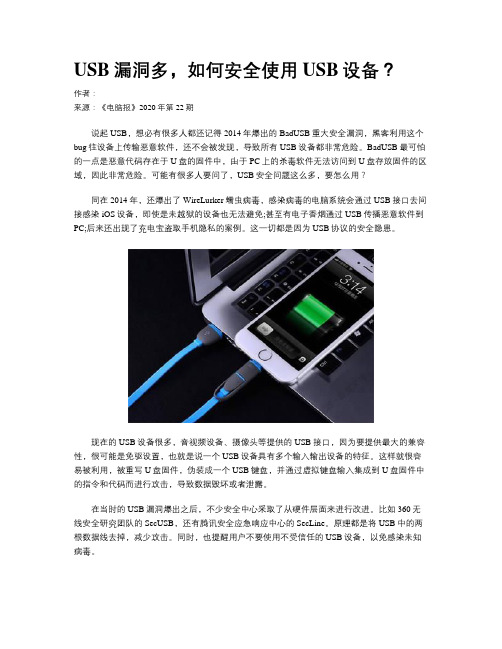
可能有很多人要问了,USB安全问题这么多,要怎么用?同在2014年,还爆出了WireLurker蠕虫病毒,感染病毒的电脑系统会通过USB接口去间接感染iOS设备,即使是未越狱的设备也无法避免;甚至有电子香烟通过USB传播恶意软件到PC;后来还出现了充电宝盗取手机隐私的案例。
这一切都是因为USB协议的安全隐患。
现在的USB设备很多,音视频设备、摄像头等提供的USB接口,因为要提供最大的兼容性,很可能是免驱设置,也就是说一个USB设备具有多个输入输出设备的特征。
这样就很容易被利用,被重写U盘固件,伪装成一个USB键盘,并通过虚拟键盘输入集成到U盘固件中的指令和代码而进行攻击,导致数据毁坏或者泄露。
在当时的USB漏洞爆出之后,不少安全中心采取了从硬件层面来进行改进。
比如360无线安全研究团队的SecUSB,还有腾讯安全应急响应中心的SecLine。
原理都是将USB中的两根数据线去掉,减少攻击。
同时,也提醒用户不要使用不受信任的USB设备,以免感染未知病毒。
尽管遇到了这样那样的问题,大家对USB的使用场景仍然很多。
毕竟对于传输数据而言,USB接口真的很方便。
近年来主板提供的USB接口也越来越多,从USB2.0到USB3.1,再到雷电3接口,匹配不同接口速度的USB设备也越来越多,这难道是因为现在USB设备已经很安全了吗?很明显不是这样的。
近日,普渡大学的Hui Peng、瑞士联邦理工学院洛桑分校的Mathias Payer所带领的研究团队,通过一个由他们创建的新工具USBFuzz发现了不同平台上的26个新USB安全漏洞。
CitrixUSB重定向策略配置
CitrixUSB重定向策略配置概要本文描述思杰USB重定向策略,提供USB重定向策略配置和规则设置的快速参考。
背景鉴于USB重定向的复杂性,详细和统一的USB重定向指导文档非常必要。
设备重定向简介通用USB重定向特性允许任意USB设备从客户机重定向到XenDesktop虚拟桌面。
利用此特性,终端用户可以在XenDesktop 会话中使用各种通用USB设备,从而获得与本地系统访问设备的相同体验。
通用USB重定向在系统底层工作,在客户机和XenDesktop虚拟桌面间重定向USB的请求和应答消息。
避免客户机上的设备驱动安装,而只需要在虚拟桌面内安装设备驱动程序。
通用USB重定向策略配置默认情况下,USB重定向是关闭的。
如果需要使用此功能,USB 重定向策略和特定的重定向规则需要开启和配置。
以下是配置步骤。
开启通用USB重定向策略此列表本人测试过的usb key列表1.招行类型23,332.建行大明五洲建行网银盾3.工行天地融二代网银Note:安装网银助手检测网银的时候手动输入网银Ukey的序列号特定USB设备设置除了通用USB重定向功能,XenDesktop对于一些特定的USB设备提供更优化的重定向方法。
一些高级功能,例如数据压缩等通过这些专用虚拟通道提供。
USB 设备类型USB 类别码专用虚拟通道USB 重定向默认设置音频设备01h RAVE关闭视频设备0Eh RAVE关闭打印机07h Printing关闭大容量存储08h CDM关闭图像设备06h TWAIN关闭智能卡0Bh Smart card关闭HID ( 键盘)03h ( Subclass code = 01,prot=01 )Keyboard关闭(不推荐键盘使用USB重定向)HID ( 鼠标)03h ( Subclass code = 01,prot=02 )Thinwire关闭(不推荐鼠标使用USB重定向)1. 假如以上设备需要USB重定向,除了配置USB重定向策略和规则外,执行以下步骤:在客户机,运行“regedit.exe”,对于32位系统,转到注册表:“HKLM\SOFTWARE\Citrix\ICA Client\Generi cUSB” ,或对于64位系统,转到“HKLM\SOFTWARE\Wow6432Node\Citrix\PortICA\GenericUSB ” ,编辑DeviceRules值,且给USB设备增加特定的Allow规则。
用AD组策略之彻低禁止USB存储设备

用AD组策略之彻低禁止USB存储设备2023-10-27•AD组策略基础介绍•禁止USB存储设备策略的制定•实施禁止USB存储设备策略•策略实施效果评估与优化•相关问题及解决方案目•总结与展望录01AD组策略基础介绍•AD组策略是一种集中式管理工具,它允许管理员在组织级别上定义和实施IT策略,以控制和规范用户行为和计算机行为。
它基于Windows Server操作系统,是活动目录(AD)的一部分,可以用于管理和配置网络中的计算机和用户。
AD组策略的定义通过AD组策略,管理员可以在组织级别上定义和实施IT策略,从而实现对整个网络中计算机和用户的集中化管理。
AD组策略的优点集中化管理AD组策略提供了丰富的配置选项和自定义功能,可以根据组织的需求进行灵活的配置和扩展。
灵活性和可扩展性AD组策略可以用于定义和实施安全性策略,包括用户身份验证、访问控制和数据保护等,从而提高网络的安全性。
安全性•AD组策略适用于各种规模的企业和组织,特别是那些需要集中化管理、灵活性和安全性需求的组织。
它可以用于控制和规范用户行为、计算机行为以及应用程序的安装、配置和管理等方面。
AD组策略的适用范围02禁止USB存储设备策略的制定通过禁止USB存储设备,减少公司信息泄露和数据安全风险。
确保公司信息安全提高工作效率合规性减少员工使用USB存储设备进行私人用途或与外部数据交换,从而专注于工作。
满足公司政策或行业规定,确保公司数据安全和合规性。
030201加密USB存储设备对于公司提供的加密USB存储设备,可以设置AD组策略来强制加密这些设备,以保护数据安全。
监控和报告建立监控机制,记录任何违反策略的行为,并采取适当的行动,例如报告给IT部门或管理层。
禁止USB存储设备通过AD组策略,将USB存储设备的使用完全禁止。
在实施策略之前,先在小范围内测试策略,以确保没有未预见的问题。
测试策略实施在实施策略后,密切关注员工的反应和策略的实际效果,并根据需要进行调整和改进。
vmwareUSB重定向
配置USB设备过滤器和重定向人机接口设备(HID)的View Client中(1011600)目的本文提供人机接口设备没有被重定向为标准的做法是VMware View,以及如何得到,如果需要它们来重定向信息。
默认情况下,查看客户端的Windows不包括从配置重定向下拉菜单中的某些设备:∙人机接口设备(HID),如USB键盘,鼠标和身份验证令牌∙这是搭配一个HID任何蓝牙设备∙智能卡阅读器和呈现自己作为智能卡读卡器的USB身份验证令牌。
这些器件被分别导向,使它们可用于在远程桌面上的验证。
USB VoIP网络电话不排除重定向,即使他们有一个附加的键盘,这是一个HID。
从View Manager 3.1.1,您可以配置列出作为可用于重定向的设备。
注意事项:∙Microsoft远程桌面协议(RDP)防止插在当地的HID,如控制台键盘,从影响远程RDP会话。
USB重定向使得设备似乎是插在本地,所以RDP还可以防止此类设备的影响远程会话。
RDP也是块的USB智能卡进行远程会话重定向。
此限制并不适用于PCoIP的。
∙VMware的PCoIP的重定向控制台会话,使当地的HID和USB设备可以连接到远程桌面会话。
如果你想重定向的HID和USB设备的控制台会话,必须使用PCoIP的作为桌面的显示协议。
∙为View Agent在Vista或Windows 7系统,Windows Mobile设备中心(WMDC)可以防止USB 设备的RDP会话的重定向。
此限制不适用于PCoIP的或RGS。
决议你必须先找出类GUID,并插入到客户端设备的供应商和产品ID。
然后,您可以使用这些值来配置重定向过滤器要在其上运行View Client的计算机。
注意:您必须在计算机上安装完整版本的View Client,您必须插入要包括或成为可用于重定向排除设备。
您可以使用设备管理器来找出类GUID以及设备的供应商和产品ID。
但是,对于某些设备,你可能要看看在View Client日志文件的信息。
UMTS信令分析大全
WCDMA信令分析总结在网络优化工作中,常常要用到信令分析的方法对问题进行定位。
熟悉信令分析,对于快速定位问题,处理投诉,异常KPI指标的分析,以及VIP用户的保障有很大的作用。
信令中涉及很多计算,只有清楚关键信息的获取和关键参数的计算方法,才能快速准确地利用信令分析问题。
本文结合实际经验并参考相关文档,对一些常用的计算方法及关键信息的查看进行了归纳,对一些重要的原理知识也做了部分解释。
适合对信令不太熟悉的初学者参考使用。
目录1基本信息类 (4)1.1PLMN,LAC, RAC,RNCID (4)1.2看CS还是PS域 (4)1.2.1根据Message Source看 (5)1.2.2从最近的RB SETUP消息看 (5)1.3看当前占用小区的CI,扰码,码字 (6)1.4CELLID的计算 (7)1.5从RL_SETUP_REQ中直接看CELLID (7)2覆盖分析类 (8)2.1RSCP和ECIO的分析 (8)2.1.1从MR中分析RSCP和ECIO (8)2.1.2从RRC CONNECT REQUEST获取RSCP和ECIO (9)2.1.3从MR中分析GSM RSSI信号强度 (9)2.2BELR的分析 (10)2.2.1BLER的分析方法 (11)2.2.2BLER的经验总结 (14)3CS业务分析类 (15)3.1看主被叫号码 (15)3.2看被叫号码 (15)3.3看当前的业务类型,以及OVSF码字 (16)3.4从SIB3消息中看小区是否被BAR掉 (17)4PS业务分析类 (19)4.1如何区分传输是IP还是ATM (19)4.2看PS是否建立在HSDPA/HSUPA上 (20)4.3看PS业务占用的IPPATH (21)4.4计算PS业务是否是384K (22)4.4.1PS 384K的计算 (22)4.4.2PS 384K的计算2 (22)4.5看终端的能力类型(如是否支持HSDPA) (23)4.6看核心网指派速率 (24)4.7PDP去激活 (25)4.8接入点APN获取 (25)4.9计算RTWP (26)4.10看分配的HSSCCH码字 (27)52ms HSUPA分析类 (27)5.1AUDIT RSP (28)5.2RRC CONN REQ (28)5.3RRC CONN SETUP (29)5.4RRC CONN SETUP CMP (31)5.5RB SETUP (32)5.6切换典型流程之2ms-10ms (33)6重选分析类 (35)6.1从SIB3中看Sintersearch (35)6.2从SIB11中看q_offset (36)6.3从SIB11中看邻区质量驻留门限 (37)7切换分析类 (37)7.1在MR中看UE上报的事件 (37)7.2在ASU中看RNC下发的切换事件 (38)7.3物理信道重配置 (39)7.4从测量控制信令中看邻区及参数 (39)7.5手机的六类测量 (40)8关于MEASUREMENT CONTROL消息的研究分析 (44)8.1概述 (44)8.2消息分析 (44)8.2.1建立measurement Identity=1质量测量控制.................. 错误!未定义书签。
微软USB设备重定向

更多灵活的重定向设置可以通过[设备安装限制] 策略实现
Computer Configuration\Administrative Templates\System\Device Installation Restrictions
演 示
Most Wanted RemoteFX Devices
RDP7.1 Client RemoteFX Devices Enumeration
/learning
/technet
/msdn
© 2008 Microsoft Corporation. All rights reserved. Microsoft, Windows, Windows Vista and other product names are or may be registered trademarks and/or trademarks in the U.S. and/or other countries. The information herein is for informational purposes only and represents the current view of Microsoft Corporation as of the date of this presentation. Because Microsoft must respond to changing market conditions, it should not be interpreted to be a commitment on the part of Microsoft, and Microsoft cannot guarantee the accuracy of any information provided after the date of this presentation. MICROSOFT MAKES NO WARRANTIES, EXPRESS, IMPLIED OR STATUTORY, AS TO THE INFORMATION IN THIS PRESENTATION.
使用Symantec1106禁止客户端USB设备的配置方法
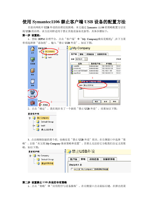
使用Symantec1106禁止客户端USB设备的配置方法目前内网机中USB外设的治理比较困难,本文通过Symantec 11.06的策略配置方法实现USB的治理,该方法同样适用于禁止其他设备如光驱等,具体步骤如下:第一步设置组:1、登陆SEPM治理平台,点击〝客户端〞→〝My Company(确实是根组)〞,在下方菜单项选择择〝添加组〞,输入〝禁止USB外设〞,如以下图:2、点击〝确定〞,我们现在有了一个新组〝禁止USB外设〞,结果如以下图:3、点击刚刚创建的那个组,也确实是〝禁止USB外设〞组名,在右侧窗口中选择〝策略〞,去除〝从父组My Company继承策略和设置〞,否那么无法给它分配我们自定义的策略,如以下图:第二步设置禁止USB外设的专有策略1、点击〝策略〞→〝应用程序与设备操纵〞,在右侧窗口点击鼠标右键,在弹出的菜单中选择〝添加〞,如以下图:2、在弹出的窗口右侧,我们在〝策略名称〞的内容后面加上〝—NoUSB〞以示区别,如以下图。
如此能够为我们以后的治理提供方便。
3、点击〝设备操纵〞,在〝禁止的设备〞栏目下方点击〝添加〞,如以下图:4、在弹出的设备选择窗口中,点击〝USB〞,然后确定。
5、在下方〝不禁止的设备〞处点击〝添加〞,这一步专门重要,不做此处理的话客户端机器中的所有USB设备都会被禁止,包括鼠标和键盘。
我们在那个地点设置让symantec 排除需要的设备。
在弹出的设备选择中点击第一个设备〝Human interface Devices〞,然后确定:好了,现在的结果应该如以下图:接下来勾选当前窗口左下角的〝当设备被禁止时提示用户〞,然后点击〝指定消息文本〞,在弹出的对话框中输入自定义内容,然后确定。
那个提示会在客户插入U盘等USB 设备时提示客户,操作如以下图:6、禁止USB设备的策略差不多配置完毕,现在点击〝确定〞,退出设置窗口,现在系统会提示,问你是否要将此策略分配,选择〝是〞:7、在随后弹出的窗口中我们选择前面创建的组〝禁止USB外设〞,然后点击〝分配〞,,假如现在组名是灰色,那么请你认真阅读第一步,如以下图:接着提示如下,选择〝是〞:8、现在,我们看看结果,点击〝客户端〞,按如下步骤操作,现在能看到那个组差不多应用了新的策略,如以下图:9、我们明白Symantec 客户端用户是能够使用命令〔在〝运行〞中敲smc –stop停止客户端,smc –start启动客户端〕退出的,假如客户退出客户端程序,那么我们设置的禁止USB 策略就会不起作用,因此我们还要进行下面两个设置:1〕为客户端加个密码:点击〝常规设置〞在弹出的窗口中选择〝安全设置〞,勾选如以下图,并设置一个治理员自己容易经历的密码,如此客户端就不能自行停止或卸载symantec的治理了,那个密码不要忘了,否那么客户端无法卸载。
HDS USPV产品简介
8、1、HDS USP-V磁盘存储产品介绍HDS USP-V存储系统内部架构HDS USP V架构同样采用HDS久负盛名的高性能、无瓶颈的Universal Star Network全光纤交换结构(第四代 Hi-Star架构)。
Hi-Star全光纤交换式结构是HDS公司秉承了多年大型主机的设计理念,将众多大型主机中的成熟、高效的技术应用于存储系统之上,在2000年推出了第一代Hi-Star全光纤交换式结构的高端存储系统――9900,该产品一经推出就受到广大高端用户的肯定,在存储业界竖立了高性能、高可靠性、高扩展性的高端存储系统形象。
在2002年HDS公司在原有Hi-Star结构基础上提高CSW的运算能力,增加内部通道数量和带宽,升级前后端控制器上的CPU,推出了基于Hi-Star II结构的9900V高端存储系统,该系统的性能、扩展性、可靠性等全面超过9900,成为HDS公司又一个成功的高端存储系统。
2007年,HDS公司推出了第四代全光纤交换式体系架构――Universal Star Network,并且基于该架构推出了具有划时代意义的HDS USP V超高端存储系统,该系统性能、扩展性等方面全面超越目前业界已有的高端存储系统,而且提供了全面的虚拟存储解决方案,使异构存储系统互联互通成为可能。
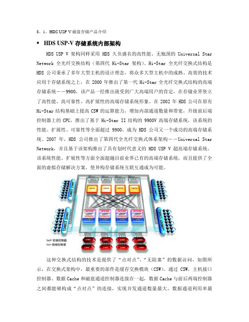
这种交换式结构的技术是提供了“点对点”、“无阻塞”的数据访问,如图所示,在交换式架构中,最重要的部件是缓存交换模块(CSW)。
通过CSW,主机接口控制器、数据Cache和磁盘通道控制器连接在一起,数据Cache与前后两端控制器之间都能够构成“点对点”的连接,实现并发通道数量最大,数据通道利用率最高。
通过使用交换式的结构,使HDS USP V磁盘存储系统具有了良好的扩展能力,前端的主机通道控制器、后端磁盘通道控制器和Cache都能够在线的、灵活的进行升级,从而降低了系统升级的投资。
存储系统并发处理能力越高,就意味着可以处理更多的应用系统读写请求,进一步提高整个系统的性能。
Win10一个USB设备描述符请求失败如何处理?
Win10⼀个USB设备描述符请求失败如何处理?安装Windows10-14986版系统以后,⽆线⽹络⽆法显⽰,进⼊设备管理器,发现通⽤串⾏总线控制器下的Unknown USB Device(Device Descniptor Request Failed)有黄⾊【!】,其属性中显⽰:A request for the USB device descriptor failed.⼀个USB设备描述符请求失败。
如何处理⼀个USB设备描述符请求失败的问题和解决⽆线⽹络的问题呢?⽅法:1、安装Windows10-14986版系统以后,⽆线⽹络⽆法显⽰,点击任务栏右下⾓的⽹络图标,没有发现⽆线⽹络;2、进⼊设备管理器,发现【通⽤串⾏总线控制器】下有⼀项带有黄⾊【!】的Unknown USB Device(Device Descniptor Request Failed)项,其属性中显⽰:A request for the USB device descriptor failed.⼀个USB设备描述符请求失败。
补充:升级到15048版系统时,同样出现任务栏右下⾓的⽹络图标中没有⽆线⽹络,进⼊设备管理器,发现【通⽤串⾏总线控制器】下有⼀项带有黄⾊【!】未知USB设备(设备描述符请求失败)。
3、Windows10⼀个USB设备描述符请求失败⽽导致⽆线⽹络不显⽰的解决⽅法右键点击系统桌⾯左下⾓【开始】,在开始菜单中点击【运⾏】,在运⾏对话框中输⼊:services.msc命令,打开服务窗⼝;4、在服务窗⼝,我们找到Plug and Play并左键双击Plug and Play,打开Plug and Play的属性窗⼝:如果Plug and Play的启动类型为:⼿动,服务状态为:正在运⾏,则将启动类型更改为:禁⽤,服务状态为:已停⽌,然后再将启动类型为:⼿动或⾃动,服务状态为:正在运⾏;如果Plug and Play的启动类型为:禁⽤,服务状态为:已停⽌,则将启动类型更改为:⼿动或⾃动,服务状态为:正在运⾏;现在Plug and Play的启动类型为:⼿动,服务状态为:正在运⾏;5、在启动类型栏中点击⼩勾,选⽤【禁⽤】,点击:应⽤ - 停⽌ - 确定;6、重新点击Plug and Play,打开Plug and Play的属性窗⼝,在启动类型栏中点击⼩勾,选⽤【⼿动】或【⾃动】,点击:应⽤;7、点击应⽤后“启动”项为可点击状态,我们点击:启动;8、当启动类型为:⼿动或⾃动,服务状态为:正在运⾏时,点击:确定;9、回到服务窗⼝,可以看到:Plug and Play 正在运⾏⾃动点击窗⼝左上⾓的【⽂件】,在下拉菜单中点击【退出】,退出服务窗⼝。
usb重定向「usb重定向功能已禁用」
usb重定向「usb重定向功能已禁用」分辨率不对首先判断是所有高拍仪拍照模糊,还是单台出现模糊现象,如果是所有高拍仪出现这类情况,需要检查策略如果是单台高拍仪,检查高拍仪的分辨率设置编辑策略,使用USB端口重定向开启高级设置调整摄像头最大宽度最;不能实现在显示的同时输出到文本只能二选其一如果要实现输出到文本的话,可以使用重定向操作符c\ping_resulttxt如果想要在atxt文件中追加的话,用下面这行命令c\ping_。
倘若计算机系统可以正常发现其他USB设备,就要考虑打印机的驱动程序是否安装正确,例如打印机驱动程序版本可能比较陈旧,或者在安装驱动程序时,不小心带上了病毒等,都有可能导致打印机无法正确安装此时,你不妨用最新版本的杀毒工具,来对计算机。
usb重定向器客户端1、无法开机原因分析 1,先检查BIOS中的设置,如果USB设备引导在硬盘引导前的话,在硬盘还没有引导时,会从USB设备引导而USB接口上连接的U盘或者移动硬盘没有可引导的操作系统,在引导时会卡在加载系统的地方不动,造成无法。
2、可以重定向一些 USB 设备,而且可以重定向剪贴板重定向设备和资源的步骤通过单击开始按钮,打开远程桌面连接在搜索框中,键入远程桌面连接,然后在结果列表中单击“远程桌面连接”单击“选项”,然后单击“本地资源。
3、虚拟机是不兼容加密狗的,但可以基于EastFax USB Server实现远程连接加密狗,把加密狗插在一个USB服务器的设备上,虚拟机就能检测到加密狗了。
4、USB的可以安装的,现在云电脑都有USB重定向的,可以直接使用的把驱动安装好就行若磐回答,希望可以帮到你。
5、错误代码通常表示iTunes无法通过端口80或443联系服务器这可能是由于受到过期或配置不正确的安全软件或防火墙软件的干扰hosts文件中的某一条目重定向对的请求,或由于Internet代理设置所致另外,当。
6、串口助手当然可以正点原子里面有串口初始化的例程你在打印的时候,为了保证你可以看见,建议你写在死循环中。
DS2208数字扫描器产品参考指南说明书
-05 Rev. A
6/2018
Rev. B Software Updates Added: - New Feedback email address. - Grid Matrix parameters - Febraban parameter - USB HID POS (formerly known as Microsoft UWP USB) - Product ID (PID) Type - Product ID (PID) Value - ECLevel
-06 Rev. A
10/2018 - Added Grid Matrix sample bar code. - Moved 123Scan chapter.
-07 Rev. A
11/2019
Added: - SITA and ARINC parameters. - IBM-485 Specification Version.
No part of this publication may be reproduced or used in any form, or by any electrical or mechanical means, without permission in writing from Zebra. This includes electronic or mechanical means, such as photocopying, recording, or information storage and retrieval systems. The material in this manual is subject to change without notice.
北信源内网安全管理系统用户使用手册

北信源内网安全管理系统用户使用手册北京北信源软件股份有限公司二〇一一年支持信息在北信源内网安全管理系统使用过程中,如您有任何疑问都可以通过访问我公司网站http://www.vrv。
com。
cn或者致电我司客服中心获得帮助和支持!热线支持:400—8188—110客户服务电话:010—62140485/86/87在您使用该产品过程中,如果有好的意见或建议的话也请联系我们的客服中心,感谢您对我公司产品的信任和支持!正文目录第一章概述 (1)特别说明 (1)产品构架 (1)应用构架 (3)第二章北信源内网安全管理系统 (5)策略中心 (5)策略管理中心 (5)网关接入认证配置 (26)阻断违规接入管理 (26)补丁分发 (26)数据查询 (26)本地注册情况统计 (27)本地设备资源统计 (27)本地设备类型统计 (27)USB标签信息查询 (27)设备信息查询 (28)审计数据查询 (29)分发数据查询 (29)非Windows操作系统设备 (30)终端管理 (30)终端管理 (30)行为控制 (30)远程协助 (31)运维监控 (31)报表管理 (32)报警管理 (32)报警数据查询 (33)本地区域报警数据统计 (33)本地报警数据汇总 (33)级联总控 (33)级联注册情况统计 (33)级联设备资源统计 (33)级联设备类型统计 (34)级联管理控制 (34)区域管理器状态查询 (35)区域扫描器状态查询 (35)级联上报数据 (36)级联报警数据 (36)系统维护 (36)系统用户分配与管理 (36)用户设置 (39)数据重整 (39)审计用户 (40)第三章北信源补丁及文件分发管理系统 (42)区域管理器补丁管理设置 (42)补丁下载配置 (42)文件分发策略配置 (43)策略中心 (43)软件分发策略 (46)其他策略 (47)补丁分发 (47)补丁自动下载分发 (48)补丁下载服务器 (48)补丁库分类 (49)补丁下载转发代理 (49)客户端补丁检测(一) (50)客户端补丁检测(二) (52)第四章北信源主机监控审计系统 (53)策略中心 (53)行为管理及审计 (53)涉密检查策略 (55)其他策略 (55)数据查询 (55)第五章北信源移动存储介质使用管理系统 (57)策略中心 (57)可移动存储管理 (57)其他策略 (57)数据查询 (57)第六章北信源网络接入控制管理系统 (59)网关接入配置认证 (59)策略中心 (60)接入认证策略 (60)其他策略 (64)环境准备方法 (64)安装RADIUS (windows IAS) (64)各厂商交换机配置 (83)Cisco2950配置方法 (83)华为3COM 3628配置 (84)锐捷RGS21配置 (87)第七章北信源接入认证网关 (89)网关接入配置认证 (89)策略中心 (90)第八章系统备份及系统升级 (92)系统数据库数据备份及还原 (92)系统组件升级 (92)区域管理器、扫描器模块升级 (92)升级网页管理平台 (93)客户端注册程序升级 (93)检查系统是否升级成功 (93)级联管理模式升级及配置 (93)附录 (95)附录(一)北信源内网安全管理系统名词注释 (95)附录(二)移动存储设备认证工具操作说明 (95)USB标签制作 (95)USB标签制作工具 (97)移动存储审计策略 (109)移动存储审计数据 (110)附录(三)主机保护工具操作说明 (110)附录(四)组态报表管理系统操作说明 (111)模版制定 (111)报表输出 (117)附录(五)报警平台操作说明 (120)设置 (120)日志查询 (123)窗口 (123)更换界面 (124)帮助 (124)附录(六)漫游功能说明 (124)漫游功能介绍 (124)漫游功能配置 (126)附录(七)IIS服务器配置说明 (130)WIN2003—32位IIS配置说明 (130)WIN2003—64位IIS配置说明 (132)WIN2008-64位IIS配置说明 (134)图目录图1—1北信源终端安全管理应用拓扑 (4)图2—1创建新策略 (5)图2—2下发策略 (6)图2—3策略控制 (6)图2-4硬件设备控制 (8)图2-5软件安装监控策略 (10)图2—6进程执行监控策略 (11)图2-7进程保护策略 (12)图2-8协议防火墙策略 (15)图2—9注册表 (16)图2-10IP与MAC绑定策略 (17)图2—11防违规外联策略 (19)图2—12违规提示 (19)图2-13文件备份路径设置 (23)图2—14注册码配置 (25)图2-15阻断违规接入控制设置 (26)图2-16本地注册情况信息 (27)图2—17本地设备资源信息 (27)图2-18本地设备类型统计 (27)图2—19软件变化信息 (29)图2—20注册日志信息 (29)图2-21交换机扫描管理配置 (32)图2—22设备信息统计图表 (33)图2—23级联设备信息 (34)图2—24级联设备系统类型统计 (34)图2-25级联管理控制 (35)图2—26下级级联区域管理器信息 (35)图2-27区域管理器状态信息 (35)图2—28区域扫描器状态信息 (35)图2—29级联上报数据 (36)图2—30系统用户列表 (36)图2-31添加系统用户界面 (37)图2—32用户管理列表 (37)图2-33终端控制权限 (38)图2-34屏幕监控权限 (38)图2—35密码初始化提示框 (39)图2—36密码初始化完成提示框 (39)图2-37修改ADMIN用户密码 (39)图2—38数据重整信息表 (40)图2-39审计用户登录 (40)图3-1区域管理器补丁管理设置 (42)图3—2分发参数设置 (43)图3-3补丁自动分发 (45)图3-4补丁下载服务器界面 (48)图3-5补丁下载服务器设置 (49)图3-6补丁代理传发支持 (50)图3-7补丁下载设置 (50)图3—8登录页面 (51)图3—9工具下载页面 (51)图3-10补丁检测中心 (52)图3—11客户端补丁漏打检测 (52)图6—2重定向配置 (60)图6—3用户添加 (60)图6—4补丁与杀毒软件认证策略 (61)图6—5接入认证策略 (62)图6—6802.1X认证界面 (63)图6-7802.1X认证界面 (63)图6-8安全检查没有通过,802。
Windows 10 Mobile 和 Windows Phone 8.1 版 Cisco AnyC
Windows 10 移动版和 Phone 8.1 版 CiscoAnyConnect 安全移动客户端 4.1.x 版本说明首次发布日期: 2015年05月01日上次修改日期: 2016年03月04日Windows Phone版 AnyConnect 版本说明Windows 10 移动版和 Windows Phone 8.1 设备版 AnyConnectAnyConnect安全移动客户端为远程用户提供与思科ASA5500系列的安全VPN连接。
通过该客户端,用户能够无缝、安全地远程访问企业网络,使安装的应用可如同直接连接到企业网络一般进行通信。
AnyConnect支持通过IPv4或IPv6隧道连接到IPv4和IPv6资源。
本文档专为AnyConnect安全移动客户端和自适应安全设备(ASA)5500的系统管理员编写,用于补充Cisco AnyConnect安全移动客户端版本4.1管理员指南,并为Windows Phone设备上运行的AnyConnect提供版本特定信息。
该AnyConnect应用仅在Windows应用商店中提供。
思科不分发AnyConnect移动应用,您也不能从ASA部署该移动应用,但是,您可以从ASA为桌面设备部署其他版本的AnyConnect,并同时支持此移动版本。
AnyConnect 移动版支持策略思科支持应用商店当前提供的AnyConnect版本;但是,修复和增强功能仅在最新发行的版本中提供。
AnyConnect 许可若要连接到ASA头端,需提供AnyConnect4.x Plus或Apex许可证;试用许可证可用;请参阅CiscoAnyConnect订购指南。
有关最新的最终用户许可协议,请参阅思科最终用户许可协议,AnyConnect安全移动客户端版本4.x。
有关我们的开源许可确认,请参阅适用于移动设备的Cisco AnyConnect安全移动客户端版本4.0中使用的开源软件。
如何避免使用未知来源的USB设备
如何避免使用未知来源的USB设备随着计算机技术的发展,USB设备越来越普及,已经成为了我们日常生活和工作中必不可少的设备之一。
然而,如果我们使用未知来源的USB设备,就会带来安全隐患,甚至会影响我们的计算机系统的正常运行。
本文将从以下几个方面来介绍如何避免使用未知来源的USB 设备,确保我们的计算机系统的安全。
一、了解USB设备的分类USB设备可以分为三种类型:低功耗设备(LPL),常规设备(FHL)以及高速设备(HSH)。
其中,LPL是指电流小于100毫安,而FHL和HSH则电流大于100毫安。
因此,我们在使用USB设备的时候,应该根据自己的需求选择相应的设备,避免使用来路不明的设备,以免给自己带来不必要的麻烦。
二、选择正规品牌的USB设备我们在选择USB设备的时候,一定要选择正规品牌的产品。
正规品牌的USB设备质量有保障,而且售后服务也更加贴心周到,避免由于设备本身的问题而给我们带来不便和安全隐患。
同时,正规品牌的产品相对来说也更加安全可靠,尽量购买有授权认证的产品。
三、在使用USB设备之前做好安全防范措施在使用USB设备之前,应该做好安全防范措施。
例如,我们可以安装杀毒软件和防火墙来保护计算机系统的安全。
同时,我们还可以关闭自动播放功能,以免自动运行病毒或者恶意软件,给我们带来损失。
四、及时更新最新的补丁和安全程序为了保障计算机系统的安全,我们需要及时更新最新的补丁和安全程序。
因为,恶意软件和病毒往往是利用计算机系统的漏洞或者安全漏洞攻击我们的计算机系统,因此我们及时更新最新的补丁和安全程序就可以让我们的计算机系统免受恶意软件和病毒的攻击。
五、不轻易使用未知来源的USB设备最后,我们要牢记不轻易使用未知来源的USB设备。
因为,这样的设备可能携带着病毒或者恶意软件,轻则影响系统运行,重则可能泄露我们的个人隐私,给我们带来更加严重的损失。
因此,在我们使用USB设备的时候,一定要选择正规品牌的产品,并且在使用之前做好安全防范措施,避免使用未知来源的设备。
RKS-G4028系列28G端口(带802.3bt PoE选项)全Gigabit模块管理以太网交换机
RKS-G4028Series28G-port (with 802.3bt PoE option)full Gigabit modular managed EthernetswitchesFeatures and Benefits•Meets a wide range of demands from Fast Ethernet to full Gigabit industrialnetworks (up to 28Gigabit ports)•Modular interfaces for flexible connector type combinations •Support for IEEE 802.3bt PoE for up to 90W output per port •High EMC immunity compliant with IEC 61850-3and IEEE 1613•Hardware-based IEEE 1588PTP for high-precision time synchronization •Turbo Ring and Turbo Chain (recovery time <20ms @250switches)1,andSTP/RSTP/MSTP for network redundancy•-40to 75°C operating temperature range•Supports MXstudio for easy,visualized industrial network management •Developed according to the IEC 62443-4-1and compliant with the IEC62443-4-2industrial cybersecurity standardsCertificationsIntroductionThe RKS-G4028Series is designed to meet the rigorous demands of mission-critical applications for industry and business,such as power substation automation systems (IEC 61850-3,IEEE 1613),railway applications (EN 50121-4),and factory automation systems.The RKS-G4028Series’Gigabit and Fast Ethernet backbone,redundant ring,and 24VDC,48VDC,or 110/220VDC/VAC dual isolated redundant power supplies increase the reliability of your communications and save on wiring costs.The modular design of the RKS-G4028Series also makes network planning easy,and allows greater flexibility by letting you install up to 28Gigabit ports with various connector types.Additional Features and Benefits•Layer 3switching functionality to move data and information across networks (L3models only)•IEEE 1588v2PTP (Precision Time Protocol)for network time synchronization•Command line interface (CLI)for quickly configuring major managed functions•IGMP snooping and GMRP for filtering multicast traffic•Port-based VLAN,IEEE 802.1Q VLAN,and GVRP to ease network planning•QoS (IEEE 802.1p/1Q and TOS/DiffServ)to increase determinism •IEEE 802.3ad,LACP for optimum bandwidth utilization •Line-swap fast recovery•TACACS+,IEEE 802.1X,SNMPv3,HTTPS,and SSH to enhance network security•SNMPv1/v2c/v3for different levels of network management •RMON for proactive and efficient network monitoring•Bandwidth management prevents unpredictable network status with “Lock port”to restrict access to authorized MAC addresses •Port mirroring for online debugging•Automatic warning by exception through email and relay output •Automatic recovery of connected device’s IP addresses•Configurable by web browser,Telnet/serial console,CLI,Windows utility,and ABC-02-USB automatic backup configuratorSpecificationsInput/Output InterfaceAlarm Contact Channels1relay output with current carrying capacity of 2A @24VDC1.If the port link speed is 1Gigabit or higher,the recovery time is <50ms.Ethernet Interface10/100/1000BaseT(X)Ports(RJ45connector)RKS-G4028-4GT models:4RKS-G4028-L3-4GT models:4100/1000BaseSFP Slots RKS-G4028-4GS models:4RKS-G4028-L3-4GS models:4RKS-G4028-PoE-4GS models:4RKS-G4028-L3-PoE-4GS models:4Module There are3module slots on the ers can select different types of modules toinsert into the switch.The modules that can be selected include8-port/6-port moduleswith10/100/1000BaseT(X),10/100BaseT(X),100/1000BaseSFP,or100BaseFX(SC/STconnector)interfaces.Refer to Expansion Modules in the Accessories section for a full list of supportedinterface modules.Standards IEEE802.1D-2004for Spanning Tree ProtocolIEEE802.1p for Class of ServiceIEEE802.1Q for VLAN TaggingIEEE802.1s for Multiple Spanning Tree ProtocolIEEE802.1w for Rapid Spanning Tree ProtocolIEEE802.1X for authenticationIEEE802.3for10BaseTIEEE802.3ab for1000BaseT(X)IEEE802.3ad for Port Trunk with LACPIEEE802.3u for100BaseT(X)and100BaseFXIEEE802.3x for flow controlIEEE802.3z for1000BaseSX/LX/LHX/ZXIEEE802.3bt for Power over EthernetEthernet Software FeaturesManagement IPv4/IPv6Note:IPv6is available for L2models only.Flow controlBack Pressure Flow ControlDHCP Server/ClientARPRARPLLDPLinkup DelaySMTPSNMP TrapSNMP InformSNMPv1/v2c/v3RMONTFTPSFTPHTTPHTTPSTelnetSyslogPrivate MIBFiber checkDHCP Relay Agent(Option82)Port Mirroring(SPAN,RSPAN)Filter GMRPGVRPGARP802.1QIGMP Snooping v1/v2/v3IGMP QuerierRedundancy Protocols STPRSTPTurbo Ring v2Turbo ChainRing CouplingDual-HomingMRPLink AggregationNetwork Loop ProtectionMSTPRouting Redundancy L3models:VRRPSecurity Broadcast storm protectionRate LimitAccess control listStatic port lockSticky MACHTTPS/SSLSSHRADIUSTACACS+Login and password policySecure bootMAC authentication bypassTrust access controlDynamic ARP InspectionDHCP SnoopingIP Source GuardTime Management SNTPIEEE1588v2PTP(hardware-based)Supported power profiles:IEEE1588Default2008,IEC61850-9-3-2016,IEEE C37.238-2017NTP Server/ClientNTP AuthenticationProtocols IPv4/IPv6Note:IPv6is available for L2models only.TCP/IPUDPICMPARPRARPTFTPDNSNTP ClientDHCP ServerDHCP Client802.1XQoSHTTPSHTTPEtherNet/IPModbus TCPTelnetSMTPSNMPv1/v2c/v3RMONSyslogUnicast Routing L3models:OSPF,Static RouteMIB P-BRIDGE MIBQ-BRIDGE MIBIEEE8021-SPANNING-TREE-MIBIEEE8021-PAE-MIBIEEE8023-LAG-MIBLLDP-EXT-DOT1-MIBLLDP-EXT-DOT3-MIBSNMPv2-MIBRMON MIB Groups1,2,3,9Power Substation MMS1588PTP Power Profile IEC61850-9-31588PTP Power Profile C37.238-2017Switch PropertiesIGMP Groups1024Jumbo Frame Size9.6KBMAC Table Size16KMax.No.of VLANs256Packet Buffer Size 1.5MbitsPriority Queues8VLAN ID Range VID1to4094USB InterfaceStorage Port USB Type AMicroSD InterfaceStorage Port MicroSD cardSerial InterfaceConsole Port RS-232(RJ45)Power ParametersTotal PoE Power Budget PoE models:300WMax.PoE Power Output per Port PoE models:IEEE802.3af:15.4WIEEE802.3at:30WIEEE802.3bt:90WInput Voltage RKS-G4028-LV models:24/48VDCRKS-G4028-2LV models:24/48VDC(redundant power supplies)RKS-G4028-HV models:110/220VAC,110/220VDCRKS-G4028-2HV models:110/220VAC,110/220VDC(redundant power supplies)PoE models:48VDC(for the PoE system)Operating Voltage RKS-G4028-LV/2LV models:18to72VDCRKS-G4028-HV/2HV models:88to300VDC,85to264VACPoE models:46to57VDC(for the PoE system)Overload Current Protection SupportedReverse Polarity Protection SupportedInput Current RKS-G4028-LV/2LV models:Max.2.53A@24VDCMax.1.25A@48VDCRKS-G4028-HV/2HV models:Max.0.55A@110VDCMax.0.29A@220VDCMax.1.01A@110VACMax.0.62A@220VACEPS(PoE models only):Max.7.50A@48VDCPower Consumption(Max.)RKS-G4028-LV/2LV models:Max.60.72W@24VDCMax.60W@48VDCRKS-G4028-HV/2HV models:Max.60.5W@110VDCMax.63.8W@220VDCMax.62.2W@110VACMax.64.1W@220VACNote:These are the maximum power consumption ratings for the device with themaximum number of modules installed.Physical CharacteristicsIP Rating IP30Dimensions440x44x300mm(17.32x1.37x11.81in)Weight RKS-G4028-LV/HV models:4900g(10.80lb)RKS-G4028-2LV/2HV models:5200g(11.46lb)RKS-G4028-PoE-LV/HV models:5000g(11.02lb)RKS-G4028-PoE-2LV/2HV models:5300g(11.68lb)Installation Rack mountingEnvironmental LimitsOperating Temperature-40to75°C(-40to167°F)Storage Temperature(package included)-40to85°C(-40to185°F)Ambient Relative Humidity5to95%(non-condensing)Standards and CertificationsSafety EN62368-1UL62368-1UL61010EMC EN55032/35EMI CISPR32,FCC Part15B Class ATraffic Control NEMA TS2EMS IEC61000-4-2ESD:Contact:8kV;Air:15kVIEC61000-4-3RS:80MHz to1GHz:35V/mIEC61000-4-4EFT:Power:4kV;Signal:4kVIEC61000-4-5Surge:Power:4kV;Signal:4kVIEC61000-4-6CS:10VIEC61000-4-8PFMFIEC61000-4-11DIPsPower Substation IEC61850-3IEEE1613Railway EN50121-4Freefall IEC60068-2-32Shock IEC60068-2-27Vibration IEC60068-2-6MTBFTime RKS-G4028-4GT-HV models:572,888hoursRKS-G4028-4GT-2HV models:518,894hoursRKS-G4028-4GS-HV models:529,925hoursRKS-G4028-4GS-2HV models:483,436hoursRKS-G4028-4GT-LV models:548,589hoursRKS-G4028-4GT-2LV models:479,574hoursRKS-G4028-4GS-LV models:508,639hoursRKS-G4028-4GS-2LV models:449,160hoursRKS-G4028-PoE-4GS-HV models:508,190hoursRKS-G4028-PoE-4GS-2HV models:465,282hoursRKS-G4028-PoE-4GS-LV models:488,598hoursRKS-G4028-PoE-4GS-2LV models:433,472hoursStandards Telcordia(Bellcore),GBWarrantyWarranty Period5yearsDetails See /warrantyPackage ContentsDevice1x RKS-G4028Series switchInstallation Kit2x rack-mounting ear4x protective caps for unused SFP ports(for RKS-G4028-GS models only)8x round stickers for module screwsDocumentation1x quick installation guide1x warranty cardNote 1.Only the RKS-G4028-PoE Series and RKS-G4028-L3-PoE models support PoEfunctionality with RM-G4000-8GPoE and/or RM-G4000-8PoE modules.2.Power over Ethernet requires the48VDC external power supply(46to57VDC).3.The48VDC external power supply,SFP modules,and modules from the RM-G4000Module Series need to be purchased separately for use with this product.DimensionsOrdering InformationModel Name Max.No.ofPortsPoE Support L3Functionality Input VoltageRedundantPower SuppliesExternal PowerSupplyOperatingTemp.RKS-G4028-4GT-HV-T28––110/220VAC/VDC––-40to75°CRKS-G4028-4GT-2HV-T28––110/220VAC/VDC✓–-40to75°CRKS-G4028-4GS-HV-T28––110/220VAC/VDC––-40to75°CRKS-G4028-4GS-2HV-T28––110/220VAC/VDC✓–-40to75°CRKS-G4028-4GT-LV-T28––24/48VDC––-40to75°C RKS-G4028-4GT-2LV-T28––24/48VDC✓–-40to75°C RKS-G4028-4GS-LV-T28––24/48VDC––-40to75°C RKS-G4028-4GS-2LV-T28––24/48VDC✓–-40to75°CRKS-G4028-L3-4GT-HV-T 28–✓110/220VAC/VDC––-40to75°CRKS-G4028-L3-4GT-2HV-T 28–✓110/220VAC/VDC✓–-40to75°CRKS-G4028-L3-4GS-HV-T 28–✓110/220VAC/VDC––-40to75°CRKS-G4028-L3-4GS-2HV-T 28–✓110/220VAC/VDC✓–-40to75°CRKS-G4028-L3-4GT-LV-T28–✓24/48VDC––-40to75°CRKS-G4028-L3-4GT-2LV-T28–✓24/48VDC✓–-40to75°CRKS-G4028-L3-4GS-LV-T28–✓24/48VDC––-40to75°CRKS-G4028-L3-4GS-2LV-T28–✓24/48VDC✓–-40to75°CRKS-G4028-PoE-4GS-HV-T 28✓–110/220VAC/VDC–✓-40to75°CRKS-G4028-PoE-4GS-2HV-T 28✓–110/220VAC/VDC✓✓-40to75°CRKS-G4028-PoE-4GS-LV-T28✓–24/48VDC–✓-40to75°CRKS-G4028-PoE-4GS-2LV-T28✓–24/48VDC✓✓-40to75°CRKS-G4028-L3-PoE-4GS-HV-T 28✓✓110/220VAC/VDC–✓-40to75°CRKS-G4028-L3-PoE-4GS-2HV-T 28✓✓110/220VAC/VDC✓✓-40to75°CRKS-G4028-L3-PoE-4GS-LV-T28✓✓24/48VDC–✓-40to75°CRKS-G4028-L3-PoE-4GS-2LV-T28✓✓24/48VDC✓✓-40to75°C Accessories(sold separately)Expansion ModulesRM-G4000-8TX Fast Ethernet module with810/100BaseT(X)portsRM-G4000-8SFP Fast Ethernet module with8100BaseSFP slotsRM-G4000-8PoE Fast Ethernet module with810/100BaseT(X)IEEE802.3bt PoE portsRM-G4000-8GTX Gigabit Ethernet module with810/100/1000BaseT(X)portsRM-G4000-8GSFP Gigabit Ethernet module with8100/1000BaseSFP slotsRM-G4000-8GPoE Gigabit Ethernet module with810/100/1000BaseT(X)IEEE802.3bt PoE portsRM-G4000-6MSC Fast Ethernet module with6multi-mode100BaseFX ports with SC connectorsRM-G4000-6MST Fast Ethernet module with6multi-mode100BaseFX ports with ST connectorsRM-G4000-6SSC Fast Ethernet module with6single-mode100BaseFX ports with SC connectorsRM-G4000-4MSC2TX Fast Ethernet module with4multi-mode100BaseFX ports with SC connectors,210/100BaseT(X)portsRM-G4000-4MST2TX Fast Ethernet module with4multi-mode100BaseFX ports with ST connectors,210/100BaseT(X)portsRM-G4000-4SSC2TX Fast Ethernet module with4single-mode100BaseFX ports with SC connectors,210/100BaseT(X)portsRM-G4000-2MSC4TX Fast Ethernet module with2multi-mode100BaseFX ports with SC connectors,410/100BaseT(X)portsRM-G4000-2MST4TX Fast Ethernet module with2multi-mode100BaseFX ports with ST connectors,410/100BaseT(X)portsRM-G4000-2SSC4TX Fast Ethernet module with2single-mode100BaseFX ports with SC connectors,410/100BaseT(X)portsStorage KitsABC-02-USB Configuration backup and restoration tool,firmware upgrade,and log file storage tool for managedEthernet switches and routers,0to60°C operating temperatureABC-02-USB-T Configuration backup and restoration tool,firmware upgrade,and log file storage tool for managedEthernet switches and routers,-40to75°C operating temperatureABC-03-microSD-T MicroSD-based configuration backup and restoration tool,firmware upgrades,and log file storage toolfor managed Ethernet switches and WLAN products,-40to85°C operating temperatureSFP ModulesSFP-1FELLC-T SFP module with1100Base single-mode with LC connector for80km transmission,-40to85°Coperating temperatureSFP-1FEMLC-T SFP module with1100Base multi-mode,LC connector for2/4km transmission,-40to85°C operatingtemperatureSFP-1FESLC-T SFP module with1100Base single-mode with LC connector for40km transmission,-40to85°Coperating temperatureSFP-1G10ALC WDM-type(BiDi)SFP module with11000BaseSFP port with LC connector for10km transmission;TX1310nm,RX1550nm,0to60°C operating temperatureSFP-1G10BLC WDM-type(BiDi)SFP module with11000BaseSFP port with LC connector for10km transmission;TX1550nm,RX1310nm,0to60°C operating temperatureSFP-1G20ALC WDM-type(BiDi)SFP module with11000BaseSFP port with LC connector for20km transmission;TX1310nm,RX1550nm,0to60°C operating temperatureSFP-1G20BLC WDM-type(BiDi)SFP module with11000BaseSFP port with LC connector for20km transmission;TX1550nm,RX1310nm,0to60°C operating temperatureSFP-1G40ALC WDM-type(BiDi)SFP module with11000BaseSFP port with LC connector for40km transmission;TX1310nm,RX1550nm,0to60°C operating temperatureSFP-1G40BLC WDM-type(BiDi)SFP module with11000BaseSFP port with LC connector for40km transmission;TX1550nm,RX1310nm,0to60°C operating temperatureSFP-1G10ALC-T WDM-type(BiDi)SFP module with11000BaseSFP port with LC connector for10km transmission;TX1310nm,RX1550nm,-40to85°C operating temperatureSFP-1G10BLC-T WDM-type(BiDi)SFP module with11000BaseSFP port with LC connector for10km transmission;TX1550nm,RX1310nm,-40to85°C operating temperatureSFP-1G20ALC-T WDM-type(BiDi)SFP module with11000BaseSFP port with LC connector for20km transmission;TX1310nm,RX1550nm,-40to85°C operating temperatureSFP-1G20BLC-T WDM-type(BiDi)SFP module with11000BaseSFP port with LC connector for20km transmission;TX1550nm,RX1310nm,-40to85°C operating temperatureSFP-1G40ALC-T WDM-type(BiDi)SFP module with11000BaseSFP port with LC connector for40km transmission;TX1310nm,RX1550nm,-40to85°C operating temperatureSFP-1G40BLC-T WDM-type(BiDi)SFP module with11000BaseSFP port with LC connector for40km transmission;TX1550nm,RX1310nm,-40to85°C operating temperatureSFP-1GEZXLC SFP module with11000BaseEZX port with LC connector for110km transmission,0to60°C operatingtemperatureSFP-1GEZXLC-120SFP module with11000BaseEZX port with LC connector for120km transmission,0to60°C operatingtemperatureSFP-1GLHLC SFP module with11000BaseLH port with LC connector for30km transmission,0to60°C operatingtemperatureSFP-1GLHXLC SFP module with11000BaseLHX port with LC connector for40km transmission,0to60°C operatingtemperatureSFP-1GLSXLC SFP module with11000BaseLSX port with LC connector for1km/2km transmission,0to60°Coperating temperatureSFP-1GLXLC SFP module with11000BaseLX port with LC connector for10km transmission,0to60°C operatingtemperatureSFP-1GSXLC SFP module with11000BaseSX port with LC connector for300m/550m transmission,0to60°Coperating temperatureSFP-1GZXLC SFP module with11000BaseZX port with LC connector for80km transmission,0to60°C operatingtemperatureSFP-1GLHLC-T SFP module with11000BaseLH port with LC connector for30km transmission,-40to85°C operatingtemperatureSFP-1GLHXLC-T SFP module with11000BaseLHX port with LC connector for40km transmission,-40to85°Coperating temperatureSFP-1GLSXLC-T SFP module with11000BaseLSX port with LC connector for1km/2km transmission,-40to85°Coperating temperatureSFP-1GLXLC-T SFP module with11000BaseLX port with LC connector for10km transmission,-40to85°C operatingtemperatureSFP-1GSXLC-T SFP module with11000BaseSX port with LC connector for300m/550m transmission,-40to85°Coperating temperatureSFP-1GZXLC-T SFP module with11000BaseZX port with LC connector for80km transmission,-40to85°C operatingtemperatureSFP-1GTXRJ45-T SFP module with11000BaseT port with RJ45connector for100m transmission,-40to75°C operatingtemperatureSoftwareMXview-100MXview license for100nodesMXview-50MXview license for50nodesMXview-250MXview license for250nodesMXview-500MXview license for500nodesMXview-1000MXview license for1000nodesMXview-2000MXview license for2000nodesMXview Upgrade-50MXview license expansion for50nodes©Moxa Inc.All rights reserved.Updated June14,2023.This document and any portion thereof may not be reproduced or used in any manner whatsoever without the express written permission of Moxa Inc.Product specifications subject to change without notice.Visit our website for the most up-to-date product information.。
HP LaserJet Pro MFP M225, M226 用户指南说明书
商标声明
Adobe®、Adobe Photoshop®、Acrobat® 和 PostScript® 是 Adobe Systems Incorporated 的商标。
Apple 和 Apple 徽标是 Apple Computer, Inc. 在美国以及其它国家/地区注册的商 标。iPod 是 Apple Computer, Inc. 的商 标。iPod 只能用于合法复制,或在版权 所有者的授权下复制。请勿盗用音乐作 品。
3 部件、耗材和附件 ...................................................................................................................................... 23 订购部件、附件和耗材 ..................................................................................................................................... 24 订购 ................................................................................................................................................... 24 耗材和附件 ....................................................................................................................................... 24 更换碳粉盒 ......................................................................................................................................................... 25
