NSFC01-01-说明书正文2004-02
NSR616RF-D01线路距离保护测控装置-技术使用说明书V3.11

第五章 保护功能 .......................................................................................................................................... 11
TH-2004H型红外吸收法一氧化碳分析仪操作手册——2013.11.13

— 样气经 4/6mm 的接口管与特氟隆滤膜的尘过滤器(6)相连。
—“量程气”进气口(7)通过 4/6mm 连接管与外部量程气体相连,量程气的入口压 力应与大气压相同。 — 经分析后的废气由泵从排气口(8)排出。
(7)
(1) (6)
(2)
(3)
(4)
(5)
(8)
图 1-2 后面板图(电气接口、风扇、气体入口/排气口)
1.2 结构说明
1.2.1 前面板
分析仪的前面板包括: �总电源开关 �LCD 显示屏: —彩色 TFT 液晶屏 1024*768; —显示器依据选定的单位显示检测结果,还可显示仪器相关的重要信息。 —在主界面上选定不同的菜单,可进入相应的二级菜单(界面)的显示和操作。 —在主界面中,可进入状态显示;在状态显示界面中,可显示分析当前的工作状态 参数。 —在报警界面中,可显示报警类型和报警时间。 �触摸键: —分析仪的测试和控制功能均通过显示界面上的虚拟触摸键实现。 —在不同界面中设置有不同的触摸键,以实现不同的操作功能。 �USB 串行接口 —用于下载历史数据。
II
TH-2004H 用户手册
1 综述与特性
�
1
TH-2004H 用户手册
1.1 简介
TH-2004H 型 CO 分析仪设计用于对环境空气中的低浓度的 CO 进行连续监测。 本机应用红外吸收原理进行检测。 由于采用了最新的光学和电子技术,分析仪具有许多优点和特性,不仅易于作用, 而且维护量也低。这些特点主要表现在: ● 分析仪采用中文操作界面,菜单式结构,层次清晰,操作简便、直观。 ● 用户可随时查看分析仪的浓度、工作状态、事故报警等信息。 ● 分析仪连续测量 CO 浓度,界面按 5min 显示平均值,还可显示测量期间各小时的 均值和 24 小时均值。 ● 分析仪除具有自动校准功能外,用户还可根据实际运行情况进行手工校准,以保 证其测量精度。 ● 通过上位机和 RS-485 接口,可随时将测量数据上传至上位机,还可进行远程监 控。
海通空气系列商品说明书
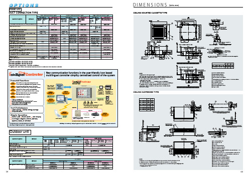
Outdoor unit1This optional accessory requires DTA102A52.2This optional accessory requires DTA107A55.3This optional accessory requires KRP1B100.4Installation plate for adaptor PCB (KRP4A95) is necessary.5In case of using KRC17-2B or field supplied remote controller, 3-Minutes Timer (field supplied) is required.Note: One set includes 5 pieces for 5units.D I ME N S I O N S(Unit: mm)D -NET Plus AdapterMobile PhoneD -NETFunction 4FunctionDCS601C5159606162636465666768697071727374o r e 00)1o r e1o r e (10)o r e 00)o r e 0)o r e 0)o r eo r e7576For R(Y)71LU-140LUFor R(Y)200KU/250KUNotes:1Obstacies height of (Pattern 1) and (Pattern 2) shall be as follows:2For the service space. if the obstacle of height exceeds the above mentioned dimensions. half of the exceeded dimensions shall be added to the standard service space.3When installing a unit. choose the most suitable one from this manual depending on actual conditions such as walking passage and ventilation.4For the service space for front side. take the service space required for field piping into account.If the number of units is more than that shown in this manual.take short circuit into account.The values represent the case for the R(Y)71 type through R(Y)140 type.The dimensions in ( ) are for the R(Y)100 and R(Y)140 type (The unit values is mm. )Front side 1500 mm Suction side 500 mm Side No (imitation)When there is an obstruction on the inlet side When there are obstructions on both the inlet and outlet sidesWhen there is an obstruction on the outlet sideWhen the obstruction on the outlet side is higher than the unit itself (There is no limit to the height of the obstruction on the outlet side.)When there are obstructions on the both sides2. For series installation (more than two units)When there are both sidesPattern 1When the overhead space is open1. For single unit installation When there is obstruction only on the inlet When the overhead space is openWhen there obstructions both sidesWhen there is an obstruction in the overhead spaceWhen there obstruction inlet sideWhen there on the both 2. For series installation (more than two units)1. For single unit installation 1. For single unit installationWhen the overhead space is open1. For single unit installation1. For single unit installation2. For series installation (more than two units)An obstructionin the An obstructionin the An obstructionin the An obstructionin the An obstructionin the 3212485136813632124858135.5025181411019589261MEMO7778。
超声波热量计说明书
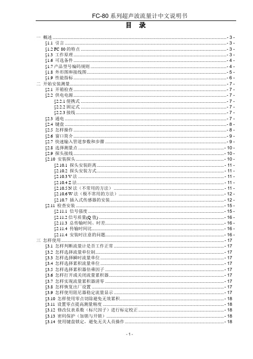
目录一概述 .............................................................................................................................................. - 3 - §1.1 引言 .................................................................................................................................... - 3 - §1.2 FC-80的特点 ....................................................................................................................... - 3 - §1.3 工作原理............................................................................................................................. - 3 - §1.6 可选备件............................................................................................................................. - 4 - §1.7产品型号编码规则 ............................................................................................................... - 4 - §1.8 外形图和接线图.................................................................................................................. - 5 - §1.9 性能指标............................................................................................................................. - 6 - 二开始安装测量................................................................................................................................ - 7 - §2.1 开箱检查............................................................................................................................. - 7 - §2.2 供电电源............................................................................................................................. - 7 - §2.2.1便携式 ....................................................................................................................... - 7 - §2.2.2固定式 ....................................................................................................................... - 7 - §2.2.3接线........................................................................................................................... - 7 - §2.3 通电 .................................................................................................................................... - 7 - §2.4 键盘 .................................................................................................................................... - 8 - §2.5 怎样操作............................................................................................................................. - 8 - §2.6 窗口简介............................................................................................................................. - 9 - §2.7 快速输入管道参数和步骤 ................................................................................................... - 9 - §2.8 选择测量点 ....................................................................................................................... - 10 - §2.9 探头接线........................................................................................................................... - 10 - §2.10 安装探头......................................................................................................................... - 10 - §2.10.1 探头安装距离........................................................................................................ - 11 - §2.10.2 探头安装方式........................................................................................................ - 11 - §2.10.3 V法 ....................................................................................................................... - 11 - §2.10.4 Z法........................................................................................................................ - 11 - §2.10.5 N法(不常用的方法) .......................................................................................... - 11 - §2.10.6 W法(极不常用的方法)...................................................................................... - 12 - §2.10.7 插入式传感器的安装............................................................................................. - 12 - §2.11 检查安装 ......................................................................................................................... - 15 - §2.11.1 信号强度 ............................................................................................................... - 15 - §2.11.2信号质量(Q值) ...................................................................................................... - 15 - §2.11.3 总传输时间、时差................................................................................................. - 16 - §2.11.4 传输时间比............................................................................................................ - 16 - §2.11.4 安装时注意的问题................................................................................................. - 16 - 三怎样使用..................................................................................................................................... - 17 -§3.1 怎样判断流量计是否工作正常 .......................................................................................... - 17 -§3.2 怎样选择流量单位制......................................................................................................... - 17 -§3.3 怎样选择瞬时流量单位..................................................................................................... - 17 -§3.4 怎样选择累积流量单位..................................................................................................... - 17 -§3.5 怎样选择累积器倍乘因子 ................................................................................................. - 17 -§3.6 怎样打开或关闭流量累积器.............................................................................................. - 17 -§3.7 怎样实现流量累积器清零 ................................................................................................. - 17 -§3.8 怎样恢复出厂设置 ............................................................................................................ - 17 -§3.9 怎样使用阻尼器稳定流量显示 .......................................................................................... - 17 -§3.10 怎样使用零点切除避免无效累积..................................................................................... - 18 -§3.11 设置零点提高测量精度 ................................................................................................... - 18 -§3.12 修改仪表系数(标尺因子)进行标定校正...................................................................... - 18 -§3.13 密码保护(加锁与开锁)................................................................................................ - 18 -§3.14 使用键盘锁定,避免无关人员操作................................................................................. - 18 -§3.15 怎样使用打印机.............................................................................................................. - 19 -§3.16 怎样使用4~20mA电流环输出........................................................................................ - 19 -§3.17 怎样输出模拟电压信号................................................................................................... - 19 -§3.18 怎样使用频率信号输出................................................................................................... - 19 -§3.19 怎样输出累积脉冲 .......................................................................................................... - 20 -§3.20 怎样产生输出报警信号................................................................................................... - 20 -§3.21 怎样使用蜂鸣器.............................................................................................................. - 20 -§3.22 怎样使用OCT输出 ........................................................................................................ - 21 -§3.23 怎样使用继电器输出....................................................................................................... - 21 -§3.24 怎样修改日期时间 .......................................................................................................... - 21 -§3.25 怎样调整LCD显示器..................................................................................................... - 21 -§3.26 怎样使用RS232/RS485串行口 ....................................................................................... - 21 -§3.27 怎样查看每日、每月、每年流量 .................................................................................... - 21 -§3.28 怎样连接压力信号和温度信号(模拟输入) .................................................................. - 21 -§3.29 怎样实现断电时间段内流量的自动补加 ......................................................................... - 22 -§3.30 怎样使用工作计时器....................................................................................................... - 22 -§3.31 怎样使用手动累积器....................................................................................................... - 22 -§3.32 怎样使用批量(定量)控制器........................................................................................ - 22 -§3.33 怎样对模拟输出进行校准 ............................................................................................... - 22 -§3.34 查看电子序列号和其他细节............................................................................................ - 22 -四命令/显示窗口详解..................................................................................................................... - 23 -§4.1 显示窗口一览表................................................................................................................ - 23 -§4.2 显示窗口顺序介绍............................................................................................................ - 24 -五问题处理..................................................................................................................................... - 41 -表1. 硬件上电自检信息及原因对策......................................................................................... - 41 -表2. 工作时错误代码原因及对策............................................................................................. - 42 -其他常见问题问答 .................................................................................................................... - 42 -六联网使用及通信协议 .................................................................................................................. - 44 -§6.1 概述.................................................................................................................................. - 44 -§6.2 流量计串行口定义............................................................................................................ - 44 -§6.3 同上位机的RS232直接联接............................................................................................. - 44 -§6.4 通信协议及其使用............................................................................................................ - 44 -§6.4.1 基本命令................................................................................................................. - 44 -§6.4.2 功能前缀和功能符号 .............................................................................................. - 46 -§6.4.3 兼容协议1.............................................................................................................. - 46 -§6.4.4 兼容协议2.............................................................................................................. - 47 -§6.5 键值编码........................................................................................................................... - 49 -§6.7 编程举例........................................................................................................................... - 49 -§7.1 功能介绍........................................................................................................................... - 50 -§7.2热量测量硬件接线............................................................................................................. - 50 -§7.3怎样进行热量测量............................................................................................................. - 50 -§7.4温度、压力等信号的量程范围设置 ................................................................................... - 51 -§7.5模拟输入的校准................................................................................................................. - 51 -§7.5联网时模拟输入量的读取.................................................................................................. - 51 -§8.1 质量保证........................................................................................................................... - 52 -§8.2 公司服务........................................................................................................................... - 52 -§8.3 产品升级........................................................................................................................... - 52 -§8.4 技术咨询........................................................................................................................... - 52 -九附录............................................................................................................................................ - 53 -§9.1常用液体声速和粘度 ......................................................................................................... - 53 -§9.2常用材料声速............................................................................................................................... - 53 -一概述§1.1 引言欢迎您选择使用性能更优异、功能更多、采用了专利技术制造的FC-80系列超声波流量计。
电磁计量泵说明书
Kompact 系列
EM00136176
Rev 1.4
感谢您购买 SEKO 计量泵,在安装和开始使用本设备之前,请仔细阅读本说明书, 未按照本说明书的要求操作而造成的任何损失,SEKO 公司将不承担任何责任。 本说明书中的内容,如有变动,恕不另行通知。 保修期限及范围 [1] 到货时,请确认所收的产品是否有破损的地方,附属品及备用品的数量是否 齐全,如在运送途中发生损坏,请依据保修规定立即联系我们。 [2] 自产品出厂之日起一年半为产品保修期。 [3] 在保修期内,用户正常使用条件下,如因设计和制造不当而导致的部件脱落 或缺陷,厂家将进行免费维修或更换。 [4] 以下情况下,用户须自行承担维修或更换的费用: 产品已过保修期;错误使用或存放 使用非厂家指定的,等级低劣的部件 非经厂家或厂家指定人员维修或改动而引起的损坏 因火灾、地震或其他自然灾害引起的损坏 [5] 厂家不承担任何因根据用户的标准、使用由用户指定的原料生产的产品的责 任。 [6] 厂家对因由所投流体引起的化学反应对产品的腐蚀或流体本身对产品的腐 蚀不承担任何责任,厂家根据用户的要求给出的产品选型,仅为推荐使用,不承 担任何使用后果。 [7] 故障或损坏原因应由用户和厂家服务工程师详细讨论后作出。 [8] 厂家不赔偿因产品使用过程中发生灾难而导致的不同的费用。 维修 产品在使用过程中,用户如发现异常,请立即停止产品运行,检查是否有部件工 作失灵(参照说明书) [1] 请联系厂家或经销商进行维修。 [2] 致电厂家或经销商要求维修前,请再次细读说明书,检查产品。 [3] 如需维修,请填写 seko《用户服务单》,以便提高维修效率:
EM00136176
Rev 1.4
9
图一
EM00136176
NSS201远动机使用说明书(14-26页)

1 智能远动设备 NSS20 NSS201
使用说明书
Version2.3
国电南瑞科技股份有限公司
2010 年 1 月
NSS200 系列智能控制器技术使用说明书
ห้องสมุดไป่ตู้
目
录
第一章 NSS201 智能远动设备.................................................................................................................... 1 1.1 NSS201 智能远动设备概述............................................................................................................ 1 1.2 NSS201 智能远动设备特点............................................................................................................ 2 1.3 硬件参数.......................................................................................................................................... 3 1.4 通信协议.....................................................................................................
9611C_060188充电保护测控装置技术和使用说明书

RCS-9611C_060188(v2.02.1)充电保护装置技术和使用说明书2南瑞继保电气有限公司版权所有本说明书适用于RCS-9611C_060188充电保护装置V2.02.1版本程序。
本说明书和产品今后可能会有小的改动,请注意核对实际产品与说明书的版本是否相符。
更多产品信息,请访问互联网:。
2目录1 概述 (5)1.1 应用范围 (5)1.2 保护配置和功能 (5)1.2.1 保护配置 (5)1.2.2 测控功能 (5)1.2.3 保护信息功能 (5)1.3 性能特征 (5)2 技术参数 (6)2.1 机械及环境参数 (6)2.1.1 机箱结构尺寸 (6)2.1.2 工作环境 (6)2.1.3 机械性能 (6)2.2 额定电气参数 (6)2.2.1 额定数据 (6)2.2.2 功耗 (6)2.3 主要技术指标 (7)2.3.1 过流保护 (7)2.3.2 零序保护 (7)2.3.3 遥信开入 (7)2.3.4 遥测量计量等级 (7)2.3.5 电磁兼容 (7)2.3.6 绝缘试验 (7)2.3.7 输出接点容量 (7)3 软件工作原理 (8)3.1 短充保护 (8)3.2 长充保护 (8)3.3 母联保护 (8)3.4 启动失灵保护 (8)3.4 装置自检 (8)3.5 装置运行告警 (8)3.6 遥控、遥测、遥信功能 (8)3.7 对时功能 (9)3.8逻辑框图 (9)4 硬件原理说明 (10)4.1装置整体结构 (10)4.2 装置面板布置 (12)4.3 装置接线端子与说明 (12)4.3.1 模拟量输入 (13)4.3.2 背板接线说明 (14)4.3.3 OUT板跳线说明 (15)4.4 结构与安装 (16)4.4.1 开关柜安装参考尺寸 (16)4.4.2 组屏安装参考尺寸 (16)15.1 系统定值 (18)5.2 保护定值 (19)5.3 通讯参数 (20)5.4 辅助参数 (21)6 使用说明 (22)6.1 指示灯说明 (22)6.2 液晶显示说明 (22)6.2.1 保护运行时液晶显示说明 (22)6.2.2 保护动作时液晶显示说明 (22)6.2.3 装置自检报告 (22)6.3 命令菜单使用说明 (23)6.3.1 装置整定 (24)6.3.2 状态显示 (24)6.3.3 报告打印 (24)6.3.4 时间设置 (24)6.3.5 报告显示 (24)6.3.6 报告清除 (24)6.3.7 装置测试 (24)6.3.8 版本信息 (25)6.4 装置的运行说明 (26)6.4.1 装置正常运行状态 (26)6.4.2 装置异常信息含义及处理建议 (26)6.4.3 安装注意事项 (26)6.5 事故分析注意事项 (27)7 装置调试大纲 (27)7.1 试验注意事项 (27)7.2 事故分析注意事项 (27)7.3 交流回路检查 (28)7.4 输入接点检查 (28)7.5 整组试验 (28)7.5.1 短充过流保护 (28)7.5.2 短充零序保护 (28)7.5.3 长充过流保护 (29)7.5.4 长充零序保护 (29)7.6 运行异常报警试验 (29)7.6.1 频率异常报警: (29)7.6.2 零序电压报警 (30)7.6.3 PT断线报警 (30)7.6.4 控制回路断线报警 (30)7.6.5 TWJ异常报警 (30)7.6.6 CT断线报警 (30)7.6.7 弹簧未储能报警 (30)7.7 装置闭锁试验 (30)27.9 装置试验菜单的说明 (31)7.10 装置与监控后台联调的说明 (32)7.10.1 遥控功能的说明 (32)7.10.2 遥测值系数的说明 (32)7.10.3 装置与后台进行通讯联调时信息文本的说明 (32)8 附录 (32)8.1 插件选配方式1 (32)8.1.1 选配插件硬件图 (33)8.1.2 选配插件背板端子图 (34)8.1.3 选配插件背板端子说明 (34)8.2 插件选配方式2 (36)8.2.1 选配插件硬件图 (36)8.2.2 选配插件背板端子图 (37)8.2.3 选配插件背板端子说明 (37)8.3 软件配合说明 (38)34RCS-9611C_060188充电保护装置技术和使用说明书1 概述1.1 应用范围RCS-9611C_060188充电保护适用于110kV以下电压等级的母线充电保护及测控,也可用作110kV以下电压等级的母联保护及测控。
菲尼克斯一号水净化设备说明说明书

R E N A L C A R EPHOENIX ONE PHOENIX ONE DSWATER TREATMENT FOR DIALYSISPHOENIX ONEPHOENIX ONE DSRE V ER SE O SMO SI SPHOENIX ONE DS SAFE, HYGIENIC, COST EFFECTIVE234OPTIMIZATION OF WATER TREATMENT AND COSTS WITH NIPRO’S PROACTIVE SERVICECONTINUOUS MONITORING• C ontinuous surveillance, recording and analysis of monitoring systems for optimal performance, ensuring reduced energy and water consumption for long-lasting savings on operational costs.• A nnual quality report based on system parameters.AUTOMATIC ERROR MESSAGING•Email notification on alarms for water treatment, heat sterilization device, or softener are directly sent to our Technical Service or an alternative address.COST EFFECTIVE REMOTE ACCESS• R emote access allows easy modification toprograms or parameter settings, error analysis, and software updates. • R educed spontaneous service calls.• T hanks to the connected unit, our TechnicalService and authorized personnel can gain access at any time and from any location.SIMPLE OPERATION• U ser-friendly interface for easy access byhealthcare professionals and dialysis technicians.• T ouch screen panel with key daily routine functions displayed.InternetContinuous monitoringAutomatic error messagingmessagingHOSPITALPATENTED PHOENIX MULTI-LOOP SERVICE CONCEPTDead zone-free permeate supply to dialysis machinesMulti Loop System - Hot Water SanitisationPHOENIX MULTI-LOOPThe presence of biofilm can cause seriouscomplications for dialysis patients. It canalso limit and deteriorate a water treatmentsystem because of poor water quality. Forthis reason, Nipro designed its multi-loopsystem to prevent biofilm formation.Starting from the main ring line made ofPVDF, the permeate supply is achievedthrough individual loops. Up to 6 dialysismachines can be connected to the loop. Byvirtue of their small diameter, connectionlines between the main loop and dialysismachines maintain a permanent high-speed flow, even when the dialysismachines are turned off. Therefore, theentire circuit is safeguarded from biofilmformation.5FULL SERVICE CONTRACT*•A nnual maintenance in accordance with maintenance protocol•S afety controls every two years•C ontinuous system monitoring via remote access•N ecessary replacement parts for repairs•T ravel and work costs for maintenance, Safety controls, and service calls•N ipro Proactive ServiceMAINTENANCE AND MONITORING CONTRACT*•A nnual maintenance in accordance with maintenance protocol•S afety controls every two years•W eekly system monitoring via remote access•T ravel and work costs for maintenance and Safety controls•N ipro Proactive ServiceYOUR PARTNER FOR CUSTOM INSTALLATIONS IN DIALYSIS CENTERS •R everse osmosis systems•H ot water sterilization systems (flow heater and tank solutions)•P ermeate ring lines made of PVDF and Polytetrafluoroethylene (PTFE)•C entral concentrate supply•M edia supply systems•D ialysis system walls•F urnishing of dialysis centers•P rofessional planning and construction of dialysis centers* Please contact your local Nipro representative for more information. Details found on back.6PHOENIX ONE IS A SINGLE STAGE RO, WHEREAS THE PHOENIX ONE DS IS A DOUBLE STAGE RO. THE DOUBLE STAGE RO ENSURES:•F ull redundancy in case of breakdown of one RO stage. Electronic motor valves facilitate immediate useof the remaining RO stage.•T he h ighest dialysis water purity.o water waste. Waste water from the second stage gets reused in the first stage.•NPhoenix One – Single Stage ROPhoenix One DS – Double Stage ROWater treatment systems of the Phoenix One DS and Phoenix One family are approved as Class IIb medical productsin accordance with EC Medical Devices Directive 93/42/EEC.7NIPRO MEDICAL AUSTRIA GMBH :Divischgasse 4, 1210 Wien, AUSTRIA | T: +43 1 532 23 14 | F: +43 1 532 23 14 89NIPRO EUROPE - EGYPT :Nile City Towers, 22nd Floor, North Tower, Nile City, Towers, Cornich El Nile, 11624 Ramelt Beaulac, Cairo, EGYPT NIPRO MEDICAL FRANCE S.A. :Biopôle Clermont-Limagne, 63360 Saint Beauzire, FRANCE | T: +33 (0)473 33 41 00 | F: +33 (0)473 33 41 09NIPRO MEDICAL GERMANY GMBH :Kokkolastrasse 5, 40882 Ratingen, GERMANY | T: +49 (0)2102 564 60 81 | F: +49 (0)2102 564 60 90NIPRO MEDICAL EUROPE NV - ITALY :Centro Direzionale Milanofiori, Strada 1 - Palazzo F1, 20090 Assago (Milano), ITALY | T: +39 (0)2 57 50 00 57 | F: +39 (0)2 57 51 81 11NIPRO MEDICAL IVORY COAST :Selmer Lot n°18, Abidjan-Cocody Riviera, Abidjan, Ivory Coast NIPRO MEDICAL EUROPE NV - NETHERLANDS :Verlengde Poolseweg 16, 4818 CL Breda, NETHERLANDS | T: +31 (0)76 524 50 99 | F: +31 (0)76 524 46 66NIPRO MEDICAL NIGERIA LTD. :9 Adelabu Close, Off Toyin Street, 100271 Ikeja, Lagos State, NIGERIA | T: +234 (0)802 706 7065NIPRO MEDICAL POLAND SP. Z O.O. :Ul. Panska 73, 00-834 Warszawa, POLAND | T: +48 (0)22 31 47 155 | F: +48 (0)22 31 47 152NIPRO EUROPE - PORTUGAL :Avd. Da Liberdade 249, 1° Andar, 1205-143 Lisboa, PORTUGAL | T: +34 (0)91 878 29 21 | F: +34 (0)91 878 28 40NIPRO MEDICAL EUROPE - RUSSIAN REPRESENTATIVE OFFICE :12 Krasnopresnenskaya Nab., Office 1407, entrance 6, 123610 Moscow, RUSSIA | T: +7 (0)495 258 1364 | T: +7 (0)495 258 1365NIPRO MEDICAL SENEGAL S.U.A.R.L. : 27 Avenue Georges Pompidou, Dakar, SENEGAL NIPRO MEDICAL D.O.O. BEOGRAD :Bastovanska 68a, 11000 Belgrade, SERBIA | T: +381 (0)11 75 15 578NIPRO MEDICAL SOUTH AFRICA (PTY) LTD :4B Dwyka Street, Stikland Industria, Cape Town, 7530, SOUTH AFRICA | T: + 27 21 949-2635 | F: +27 21 949-2397Unit 20&21, Falcon Lane, Lanseria Business Park, Erf 805 Lanseria Corporate Estate, Pelindaba Rd.,Lanseria Ext. 26, Gauteng, SOUTH AFRICA | T: + 27 11 431 1114 / 26 | F: +27 11 431 1115NIPRO MEDICAL EUROPE NV - SPAIN :Poligono Los Frailes n° 93 y 94, Daganzo, 28814 Madrid, SPAIN | T: +34 (0)91 884 5531 | F: +34 (0)91 878 2840NIPRO MEDIKAL SAĞ.HIZ.TIC.LTD.ŞTI. :Aziziye Mah.Pilot Sok.17/4, 6540 Çankaya-Ankara, TURKEY | T: +90 (0)312 442 21 12 | F: +90 (0)312 442 21 92NIPRO MEDICAL UK LTD. :25 Barnes Wallis Road, Segensworth East, Fareham Hampshire PO15 5TT, UNITED KINGDOM | T: +44 148 985 48 30Nipro Medical Europe : European Headquarters, Blokhuisstraat 42, 2800 Mechelen, Belgium T: +32 (0)15 263 500 | F: +32 (0)15 263 510 |***********************| Please contact your local representative for more information.ENNipro Renal Care is part of Nipro Corporation J apan, a leading global healthcare company established in 1954. With over 28.000 employees worldwide, Nipro serves the Medical Device, Pharmaceutical, and Pharmaceutical Packaging industries.Nipro Renal Care is a global market leader with over 5 decades providing renal solutions for dialysis and dialysis-related treatment. We specialize in developing dialysis machines, water treatment systems, and a comprehensive portfolio of disposable medical equipment.In order to address the needs of patients, healthcare professionals, and procurement managers alike, Nipro Renal Care is driven by innovation and patient safety to offer the highest quality products that optimize time, effort, and costs.BECAUSE EVERY LIFE DESERVES AFFORDABLE CAREB r o -P h o e n i x _O n e _O n e _D S - E N - 03.J u l .19P r o d u c t s a r e c o n t i n u o u s l y u n d e r r e v i e w i n t h e l i g h t o f t e c h n i c a l a d v a n c e m e n t ; t h e a c t u a l s p e c i f i c a t i o n s m a y t h e r e f o r e b e s u b j e c t t o i m p r o v e m e n t o r m o d i f i c a t i o n w i t h o u t n o t i c e . S o m e f e a t u r e s a n d /o r a c c e s s o r i e s d i s p l a y e d a n d d e s c r i b e d c o u l d b e o p t i o n a l o n d i f f e r e n t m a r k e t s . T h e i n f o r m a t i o n p r o v i d e d d o e s n o t c o n s t i t u t e a n o f f e r t o s e l l a n d i s p r o v i d e d f o r m e r e l y i n f o r m a t i o n a l p u r p o s e s . I m a g e s p u b l i s h e d i n t h e p r e s e n t d o c u m e n t a r e s h o w n e x c l u s i v e l y f o r d e m o p u r p o s e s , a r e r e p r e s e n t a t i v e o f t h e p o s s i b l e a p p l i c a t i o n s a n d m i g h t b e a d a p t e d f o r g r a p h i c n e e d s . A l l r i g h t s r e s e r v e d .。
赋安JB-SXB-FX01总线式火灾显示盘说明书

JB-SXB-FX01主机名称:火灾显示盘主机型号:FX01附录2 装箱清单此装箱单所列内容是指包装箱内应包括的设备和资料,不包括您选用的其它配件。
附录1 设备代码表第一章 显示盘简介 ‥‥‥‥‥‥‥1.1 概述 ‥‥‥‥‥‥‥‥‥‥‥1.2 主要特性 ‥‥‥‥‥‥‥‥‥1.3 主要技术参数 ‥‥‥‥‥‥‥第二章 显示盘安装 ‥‥‥‥‥‥‥第三章 操作指南 ‥‥‥‥‥‥‥3.1 开机运行 ‥‥‥‥‥‥‥‥‥3.2 功能操作说明 ‥‥‥‥‥‥‥第四章 接线说明及简单故障处理 ‥4.1 外部线路要求 ‥‥‥‥‥‥‥4.2 接线端子说明 ‥‥‥‥‥‥‥4.3 简单故障处理 ‥‥‥‥‥‥‥目 录3344577813131314附录 ‥‥‥‥‥‥‥‥‥‥‥‥‥附录 1 设备代码表 ‥‥‥‥‥‥‥‥附录 2 装箱清单 ‥‥‥‥‥‥‥‥151515JB-SXB-FX01火灾显示盘是一款智能型总线式中文界面显示的火灾显示盘。
本火灾显示盘满足国家标准GB17429-1998《火灾显示盘通用技术条件》的相关要求。
本产品的设计、制造、检验、销售及服务全过程,均符合ISO9000(2000版)质量管理体系的要求,并通过国际权威机构BSI的认证及中国国家消防电子产品质量监督检验中心检验。
4.3.1 液晶不清晰液晶不清晰时可以调主板上的可调电位器。
4.3.2 无显示显示盘液晶和指示灯没显示,可检查供电是否正常、所有接插件是否接插良。
4.3.3 声响故障显示盘在报火警情况下,没有火警报警声,可检查扬声器接线是否断线或插头接插不良。
4.3.4 时钟不准确时钟若显示不正确,通过菜单调时即可。
4.3.5 用户不能排除的故障请致电本公司的技术人员。
JB-SXB-FX01火灾显示盘是一种可用于楼层或独立防火区内的火灾报警显示装置。
火灾显示盘只能接收火灾报警控制器发出的信号,不能给火灾探测器、手动报警按钮及其他探测部件供电。
当建筑物内发生火灾后,消防控制中心的控制器接收报警信息,同时把报警信号传输到失火区域的火灾显示盘上,火灾显示盘将显示报警的设备的位置编码及相关信息,并发出声响信号,通知失火区域的人员。
NSFC01-02永磁同步交流伺服门机使用说明书
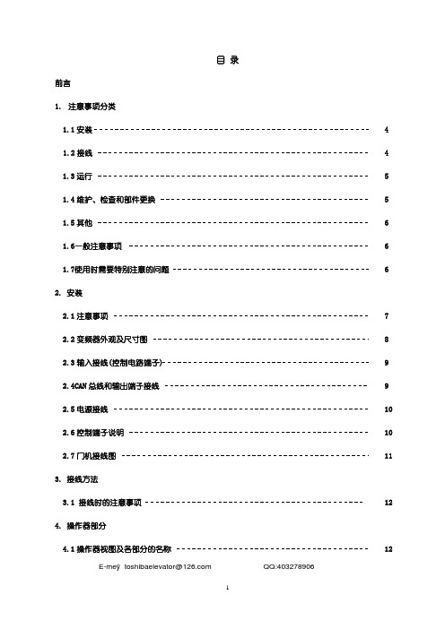
14
4.5 操作器操作实例
15
5. 门机调试的具体步骤
5.1 调整门机前的假设
16
5.1.1 运行前参数检查
16
5.1.2 门机检修试运行
17
5.1.3 门机开、关门限位输出信号极性调整
18
5.1.4 门机开门宽度测定
18
5.1.5 关门极限位置、关门慢速 1 减速位置设置
18
5.1.6 开门极限位置、开门慢速 1 减速位置设置
1.6 一般注意事项 本手册中的所有图解,为了说明详细部分的结构,有时是在取掉保护盖或遮蔽物的 情况下描画的,在产品运行时请务必按照手册的要求盖上保护盖或遮蔽物,根据使 用手册进行运行。
1.7 使用时需要特别注意的问题
◆请在周围温度容许范围内使用。-10℃~ 50℃,湿度低于90%,不结露。 电梯门控制器的寿命受周围温度的影响很大,请在容许温度范围内使用。另外,还需注意安装方向 和环境。(请参照第2.1 7页)
1 注意事项分类
安全注意事项 在安装、运行、维护、检查之前,请务必熟读此手册及其附属文件,以便正确的加以使 用。 对有关设备的情况、安全信息及其注意事项均熟练的掌握之后再加以使用。 本使用手册在安全注意事项栏中划分“危险”和“注意”两个档次。 危险:发生误操作时会出现危险状况,有可能导致死亡或重伤的情况。 注意:发生误操作时会出现危险状况,有可能导致中等程度或轻度伤害的情况。以及可能发
电源侧接线及电机侧接线如下图:
QQ:403278906
注意:不要将电机侧和电源侧接反,否则将损坏门控制器,或引起火灾。而且要保证接线正确和 牢固。
电源接线图
交流220V
图五 门控制器电源、电机接线图
2.6 控制端子说明
PCL4 01 02 04 05 液压比例遥控阀值系列说明书

Aug. 2005Spare Parts List PCL4 01/02/04/05Hydraulic Proportional Remote ControlValve SeriesConversion factors1 kg = 2.2046 lb 1 N = 0.22481 lbf 1 bar = 14.504 psi 1 l = 0.21997 UK gallon 1 l = 0.26417 US gallon1 cm 3= 0.061024 in 31 m = 3.2808 feet 1 mm = 0.03937 in 9/5 °C + 32 = °FOffer of SalePlease contact your Parker representation for a detailed ”Offer of Sale”.FAILURE OR IMPROPER SELECTION OR IMPROPER USE OF THE PRODUCTS AND/OR SYSTEMS DESCRIBED HEREIN OR RELATED ITEMS CAN CAUSE DEATH, PERSONAL INJURY AND PROPERTY DAMAGE.This document and other information from Parker Hannifin Corporation, its subsidiaries and authorized distributors provide product and/or system options for further investigation by users having technical expertise. It is important that you analyze all aspects of your application, including consequences of any failure, and review the information concerning the product or system in the current product catalogue. Due to the variety of operating conditions and applications for these products or systems, the user, through its own analysis and testing, is solely responsible for making the final selection of the products and systems and assuring that all performance, safety and warning requirements of the application are met.The products described herein, including without limitation, product features, specifications, designs, availability and pricing,are subject to change by Parker Hannifin Corporation and its subsidiaries at any time without notice.WARNING!Spare Parts List PCL401, 402, 404Publication No HY17-8813/UKContentsList of contents PagePCL401Basic valve, mounting plate M1, N, plugs, bolts etc.................4 - 5Handles PCL401, H1, E0 - E4..................................................6 - 7Handles PCL401, N0, N2, N4 etc.............................................8 - 9Handles PCL401, N0, N2, N4 etc.........................................10 - 11PCL402 (PCL404)Basic valve PCL402.............................................................12 - 13Mounting plates M2 - M6, Lever link, PCL402.......................14 - 15Detents MD2, ED2, PCL402.................................................16 - 17Friction ratchet S2, PCL402..................................................18 - 19Marine design A86, A87, A88...............................................20 - 21Handles PCL402, H3 - H7, E0 - E4.......................................22 - 23Foot pedal PCL404...............................................................24 - 25Foot pedal PCL402 + A95.....................................................26 - 27PCL405Foot pedal PCL405X, 405F...................................................28 - 29Spring Packs, Push Pin Sets have been moved to a separate document.Spare Parts List PCL401Publication No HY17-8813/UKBasic valveSpare Parts List Publication No HY17-8813/UKSpare Parts List PCL401Publication No HY17-8813/UKLever Handles= Phillips screw = Slot screw =Tightening torque (Nm)= Socket head (mm)= Hexagon (mm)Spare Parts List Publication No HY17-8813/UKSpare Parts List PCL401Publication No HY17-8813/UKLever Handles5(2x)(2)=Tightening torque (Nm)=Torx= Hexagon (mm)Spare Parts List Publication No HY17-8813/UKSpare Parts List PCL401Publication No HY17-8813/UKLever Handles5(2x)(2)=Tightening torque (Nm)=Torx= Hexagon (mm)10=888=Tightening torque (Nm)= Hexagon (mm)= Socket head (mm)424542®=Tightening torque (Nm)= Hexagon (mm)A88WA88BSpare Parts List Publication No HY17-8813/UKSpare Parts List PCL402Publication No HY17-8813/UKHandles, actuatorsH3 - H75Spare Parts List Publication No HY17-8813/UKSpare Parts List PCL4Publication No HY17-8813/UKFootpedals1360®1360=Tightening torque (Nm)= Socket head (mm)= Hexagon (mm)13Spare Parts List Publication No HY17-8813/UKSpare Parts List PCL4Publication No HY17-8813/UKFootpedals= Hexagon (mm)Spare Parts List Publication No HY17-8813/UKSpare Parts List PCL4Publication No HY17-8813/UKFootpedals=Spare Parts List Publication No HY17-8813/UKPublication No HY17-8813/UK © Copyright 2004Parker Hannifin Corporation All rights reserved.Parker Hannifin is the world’s premier supplier of motion and control systems and solutions, with sales and manufacturing facilities throughout the world. For product information and details of your nearest Parker sales office, visit us at /euro_mcd or call free on 00800 2727 5374.Hydraulics Group Sales OfficesAustria Wiener NeustadtTel: +43 (0)2622 23501Fax: +43 (0)2622 66212BelgiumNivellesTel:+32 (0)67 280 900Fax:+32 (0)67 280 999Czech RepublicPragueTel:+420 2 830 85 221Fax:+420 2 830 85 360DenmarkBallerupTel:+45 4356 0400Fax:+45 4373 8431FinlandVantaaTel:+358 (0)9 4767 31Fax:+358 (0)9 4767 3200FranceContamine-sur-Arve Tel:+33 (0)450 25 80 25Fax:+33 (0)450 03 67 37GermanyKaarstT el: +49 (0)2131 4016 0Fax: +49 (0)2131 4016 9199HungaryBudapestT el: +36 (06)1 220 4155Fax:+36 (06)1 422 1525IrelandDublinTel:+353 (0)1 293 9999Fax:+353 (0)1 293 9900Italy Corsico (MI)Tel:+39 02 45 19 21Fax:+39 02 4 47 93 40The NetherlandsOldenzaalTel:+31 (0)541 585000Fax:+31 (0)541 585459NorwaySkiTel:+47 64 91 10 00Fax:+47 64 91 10 90PolandWarsawTel:+48 (0)22 863 49 42Fax:+48 (0)22 863 49 44PortugalLeca da PalmeiraTel:+351 22 9997 360Fax:+351 22 9961 527SlovakiaRef. Czech RepublicSpainMadridTel:+34 91 675 73 00Fax:+34 91 675 77 11SwedenSpångaTel:+46 (0)8 597 950 00Fax:+46 (0)8 597 951 10United KingdomWarwickTel:+44 (0)1926 317 878Fax:+44 (0)1926 317 855InternationalEuropeAustraliaCastle HillTel:+61 (0)2-9634 7777Fax:+61 (0)2-9899 6184CanadaMilton, OntarioTel:+1 905-693-3000Fax:+1 905-876-0788ChinaBeijingTel:+86 10 6561 0520Fax:+86 10 6561 0526Asia Pacific GroupHong Kong, Kowloon Tel:+852 2428 8008Fax:+852 2425 6896IndiaMumbaiTel:+91 22 7907081Fax:+91 22 7907080JapanTokyoTel:+(81) 3 6408 3900Fax:+(81) 3 5449 7201Latin America GroupBrazilTel:+55 12 3954-5100Fax:+55 12 3954-5266South AfricaKempton ParkTel:+27 (0)11-961 0700Fax:+27 (0)11-392 7213USACleveland (industrial)Tel:+1 216-896-3000Fax:+1 216-896-4031Lincolnshire (mobile)Tel:+1 847-821-1500Fax:+1 847-821-7600。
201使用说明书(仪表)[1]
![201使用说明书(仪表)[1]](https://img.taocdn.com/s3/m/82e382e1998fcc22bcd10dc9.png)
ICS系列电子皮带秤(201仪表)使用说明书目录一、概述 (3)二、201积算器功能说明 (3)1、积算器面板说明 (3)2、键盘 (4)3、操作提示符 (4)4、错误提示符 (6)三、皮带秤基本参数的确定 (6)四、皮带秤的校准 (7)1、设置工作参数 (7)2、调零 (10)3、有关计算公式: (12)五、维护 (13)一、概述 (13)二、日常维护 (13)三、故障排除 (14)六、积算器的日常维护和常见故障的排除 (16)一、概述 (16)二、日常维护 (16)三、仪表初始化和自诊断 (17)四、总累计清除 (19)五、常见故障的排除 (19)1、无显示 (19)2、乱显示 (20)3、死机 (20)4、流量不稳 (20)5、02E消不掉-皮带下溢 (21)6、03E消不掉-皮带上溢 (21)7、常用称重传感器主要技术数据 (21)8流量 (22)9、主机板各点参考电压 (22)10、链码标定简介 (23)六、201仪表打印功能使用说明 (24)第一部分-----称重仪表本书主要针对配备201仪表的ICS-17A和ICS-20A系列皮带秤系统的安装、操作、校准和维修等方面加以介绍和说明,有关扩展板(打印和通讯)参见补充说明。
一、概述皮带秤系统安装完毕,即可按本章所述内容进行操作和校准,校准完成后,皮带秤系统将能够进行精确地称重。
二、201积算器功能说明1、积算器面板说明2、键盘所有的数字(常数或功能数)输入到积算器都要通过键盘完成,键入时,上显示器显示被键入的常数,下显示器在右边显示实际的流量,在左边显示所“设定”的操作提示符及字母“P”(00P、01P等)。
3、操作提示符4、错误提示符当有一个或更多的错误发生时,仪表自动诊断并显示出错误的提示符。
正常运行期间,错误大部分来自系统的故障和不适当的操作,参见本手册排除部分。
三、皮带秤基本参数的确定皮带秤系统在校准过程中,需要一些基本参数,这些为(1)以米为单位的皮带长度,(2)皮带圈数,试验时间,一般讲皮带整数不少于3圈,时间大于3分钟,(3)以秒为单位的精确的试验时间,(4)秤容量,由用户提供的输送机最大输送量,单位为t/h。
爱德尔非冷泉水机说明书

96917C (Rev. C - 5/04)Installation/Care/Use ManualModel: EDF214WC Non-Refrigerated FountainIMPORTANT! INSTALLER PLEASE NOTE.THE GROUNDING OF ELECTRICAL EQUIPMENT SUCH AS TELEPHONE, COMPUTERS, ETC. TO WATER LINES IS A COMMON PROCEDURE. THIS GROUNDING MAY BE IN THE BUILDING OR MAY OCCUR AWAY FROM THE BUILDING . THIS GROUNDING CAN CAUSE ELECTRICAL FEEDBACK INTO A FOUNTAIN, CREATING AN ELECTROLYSIS WHICH CAUSES A METALLIC TASTE OR AN INCREASE IN THE METAL CONTENT OF THE WATER. THIS CONDITION IS AVOIDABLE BY USING THE PROPER MATERIALS AS INDICATED. ANY DRAIN FITTINGS PROVIDED BY THE INSTALLER SHOULD BE MADE OF PLASTIC TO ELECTRICALLY ISOLATE THE FOUNTAIN FROM THE BUILDING PLUMBING SYSTEM.IMPORTANTALL SERVICE TO BE PERFORMED BY AN AUTHORIZED SERVICE PERSONTUBE IS SECURED IN POSITIONSIMPLY PUSH IN TUBE TO ATTACHPUSH IN COLLET TO RELEASE TUBEPUSHING TUBE IN BEFORE PULLING IT OUT HELPS TORELEASE TUBEFIG. 2OPERATION OF QUICK CONNECT FITTINGSFIG. 1NOTE: WATER FLOWDIRECTIONBUILDING WATER INLETSERVICE STOP (NOT FURNISHED)1/4" O.D. TUBE WATER INLET TO COOLER3/8" O.D. UNPLATEDCOPPER TUBE CONNECT COLD WATER SUPPLY96917C (Rev. C - 5/04)F IG . 3PAGE 2F I N I S H E D F L O O RD E T A I L 1L E G E N D :A = R E C O M M E N D E D W A T E R S U P P L Y L O C A T I O N 3/8 O .D . U N P L A T E D C O P P E R T U B E C O N N E C T B = R E C O M M E N D E D L O C A T I O N F O R W A S T E O U T L E T 1-1/4" O .D . D R A I N C = M O U N T I N G H O L E S F O R S E C U R I N G F O U N T A I N T O W A L LINSTALLATION INSTRUCTIONS1. Wall should already be framed for the fountain using the positioning dimensions shown in Fig. 3.Shown dimensions pertain to installation location (framing must support up to 150 lbs. weight).2. Install rough-in plumbing as shown in Fig.3. Run supply water inlet line and connect to a service stop (not provided). Turn on supply water and flush thoroughly. Close water supply.3. Remove bottom access panel from fountain basin and save the screws. Install the fountain to the wallusing (4) 5/16" bolts and washers (not provided). Bolts should be long enough to securely fasten thefountain to the wall. Tighten securely, but do not over tighten. Over tightening will crack the CompositeFountain.4. Remove elbow from end of p-trap (item 1) and attach it to drain tube. Re-attach elbow to p-trap andcut waste tube to required length using plumbing hadware and trap as guide.5. Make water supply connections from service stop to the fountain strainer (item 18) by inserting thewater inlet line into the inlet side of strainer until it reaches a positive stop about 3/4", (See Figure 2,Page 1). Turn on water supply and check for leaks. Newly installed water supply line should beinsulated after leak check is completed. DO NOT SOLDER TUBES INSERTED INTO THE STRAINERAS DAMAGE TO THE O-RINGS MAY RESULT.6. These products are designed to operate on 20-105 PSIG supply line pressure. If inlet pressure isabove 105 PSIG, a pressure regulator must be installed in the supply line. Any damage caused byreason of connecting these products to supply line pressure lower than 20 PSIG or higher than 105 PSIG is not covered by warranty.7. Check stream height from bubbler. Stream height is factory set at 45-50 PSI. If supply pressurevaries greatly from this, remove items 5 and 6 (See Figure 5, Page 4) and adjust the screw on regulator(item 10). Clockwise adjustment will raise stream height and counter-clockwise adjustment will lowerstream height. For best adjustment stream height should be approximately 1" (25mm) above the bubbler guard. (See Figure 4, Page 4).8. Replace bottom access panel to fountain basin using screws provided. Tighten securely.Care and Maintenance of Elkay FountainsThe Elkay fountain provides an exremely durable, nonporous surface which resists staining. Care is very simple. Routine cleaning with a soft sponge or cloth, or with water or non-abrasive aerosol foam cleaner, isall that is normally needed to give many years of trouble free service. Cleaners left standing on the fountain surface can dull the surface finish. Be certain to rinse all cleaning agents completely and polish with a soft cloth.Harsh abrasive cleaners are not required and should not be used.Mild abrasives such as liquid automotive cleaning compound or baking soda paste will remove simple scratches and stains. Cigarette burns can normally be removed without noticeable effect. Deeper scratches or gouges can be corrected with fine grit sandpaper (240 grit then 400 grit) or a green Scotchbrite pad.T o maintain or regain luster and make cleaning easier, periodic applications of automobile wax or like products will keep the finish looking like new.96917C (Rev. C - 5/04)PAGE 396917C (Rev. C - 5/04)PAGE 4P ART NO.ITEM NO.PARTS LISTDrainBall - Anti-Rotational Bubbler Body Retaining Nut Button CoverOrifice Assy Nipple Assembly Screen Regula torScrew - 10-24 x 1/2" PHTC Bottom - Cover Strainer - Beehive Ferrule - Tailpipe Fountain - BodyPoly Tubing (Cut To Length)Hex Nut Stra inerInsert - ThreadedLK46475575C A5510210031C 40048C 40089C 40322C 15029C 60291C 61313C 11262754389027658C 40038C 40619C 56051C 56092C 70012C 55996C 66399C12345678910111213141516171819DESCRIPTIONOrifice Assy: Mineral deposits on orifice can cause water flow to spurt or not regulate. Mineral deposits may be removed from the orifice with a small round file not over 1/8" diameter or small diameter wire.CAUTION: Do not file or cut orifice material.Stream Regulator: If orifice is free of material deposits, regulate flow as in instructions on page 3 (Step 7). If replacement is necessary, see parts list for correct regulator part number.Actuation of Quick Connect W ater Fittings: Cooler is provided with lead-free connectors which utilize an o-ring water seal. T o remove tubing from the fitting, relieve water pressure, push in on the gray collar while pulling on the tubing.(See Figure 2, Page 1). To insert tubing, push tube straight into fitting until it reaches a positive stop, approximately 3/4".TROUBLE SHOOTING & MAINTENANCEFIG. 4PRINTED IN U.S.A.161517111, 12, 1913, 14182SEE FIG. 56FIG. 691054378FIG. 517 800-518-5388。
热抗性实体自动开关说明书

No.D-※S-OMS0002-AHeat Resistant Solid State Auto SwitchD-M9#J# SeriesSafety Instructions 2 Model Indication and How to Order 8 Summary of Product parts 8 Definition and terminology 9 Mounting and Installation 10 Installation 10 Maintenance 12 Troubleshooting 13 Specification 17 Specifications 17 Dimensions 18Safety InstructionsThese safety instructions are intended to prevent hazardous situations and/or equipment damage. These instructions indicate the level of potential hazard with the labels of "Caution", "Warning" or "Danger". They are all important notes for safety and must be followed in addition to International Standards (ISO/IEC)*1), and other safety regulations.*1) ISO 4414: Pneumatic fluid power -- General rules relating to systems.ISO 4413: Hydraulic fluid power -- General rules relating to systems.IEC 60204-1: Safety of machinery -- Electrical equipment of machines .(Part 1: General requirements)ISO 10218-1992: Manipulating industrial robots -Safety.etc.Caution Caution indicates a hazard with a low level of risk which, if not avoided, couldresult in minor or moderate injury.Warning Warning indicates a hazard with a medium level of risk which, if not avoided,could result in death or serious injury.Danger Danger indicates a hazard with a high level of risk which, if not avoided, willresult in death or serious injury.Safety InstructionsLimited warranty and Disclaimer/Compliance Requirements The product used is subject to the following "Limited warranty and Disclaimer" and "Compliance Requirements".Read and accept them before using the product.∙Follow the instructions given below when designing, selecting and handling the product. ■The instructions on design and selection (installation, wiring, environment, adjustment, operation, maintenance, etc.) described below must also be followed.♦Product specifications•DC power supply to be used together must be UL 1310 class 2 power supply unit or UL recognized power supply with UL 1585 class 2 transformer. •Use the specified voltage.Otherwise failure or malfunction can result.•Do not place two or more actuators close together.When using two or more actuators closely in parallel, keep a distance of at least 40 mm between the actuator tubes to prevent magnetic interference from affecting the product, which can cause malfunction. (If the distance is specified for the actuator, use that value.)•Detection by an Auto switch mounted in a mid-stroke position depends on the piston speed. Conditions must satisfy the equation below.Wherein;Maximum detectable piston speed = V [mm/s]1000×[ms]load of time Operating [mm]switch Auto of range Operating [mm/s]V =•Design the product to prevent reverse current when the circuit is opened or the product is forced tooperate for operational check.Reverse current can cause malfunction or damage to the product.•Reserve a space for maintenance.Allow sufficient space for maintenance when designing the system.■Product handling♦Installation•Tighten to the specified tightening torque.If the tightening torque is exceeded the mounting screws and brackets may be broken. If the tightening torque is insufficient, the product can be displaced. (Refer to "Mounting and Installation".)•Be sure to ground terminal FG when using a commercially available switch-mode power supply. •Never mount an actuator equipped with Auto switch in a location that will be used as a foothold.The product may be damaged if excessive force is applied by stepping or climbing onto it.•Do not drop, hit or apply excessive shock to the Auto switch.Otherwise damage to the internal parts can result, causing malfunction.♦Wiring•Do not pull hard on the lead wire. In particular, never lift an Auto switch actuator by holding the lead wires.Otherwise damage to the internal parts can result, causing malfunction.•Avoid repeatedly bending or stretching the lead wire, or placing heavy load on them.Repetitive bending stress or tensile stress can cause the sheath of the wire to peel off, or breakage of the wire.If the lead wire can move, fix it near the body of the product.•Wire correctly.Incorrect wiring can break the product.•Do not perform wiring while the power is on.Otherwise damage to the internal parts can result, causing malfunction.•Do not route wires and cables together with power or high voltage cables.Otherwise the product can malfunction due to interference of noise and surge voltage from power and high voltage cables to the signal line. Route the wires (piping) of the product separately from power or high voltage cables. •Confirm proper insulation of wiring.Poor insulation (interference from another circuit, poor insulation between terminals, etc.) can lead to excess voltage or current being applied to the product, causing damage.•Design the system to prevent reverse current when the product is forced to operate for operational check.Depending on the circuit used, insulation may not be maintained when operation is forced, allowing reverse current to flow, which can cause malfunction and damage the product.•Keep wiring as short as possible to prevent interference from electromagnetic noise and surge voltage.Do not use a cable longer than 100 m.•Do not cut the lead wire between the sensor and amplifier.It may malfunction after connecting it again.♦Environment•Pay attention to use the product in an atmosphere with accumulation of iron waste or close contact with magnetic substances.When a large amount of iron waste such as machining chips or spatter has accumulated, or a magnetic substance (something attracted by a magnet) is brought into close proximity with the actuator, it may cause the Auto switch to malfunction due to weakening.•Do not use the product in an environment that is constantly exposed to the splash of water.This can cause insulation failure or malfunction due to swelling of the potting resin.•Do not use in a place where the product could be splashed by oil or chemicals.If the product is to be used in an environment containing oils or chemicals such as coolant or cleaning solvent, even for a short time, it may be adversely affected. (insulation failure, malfunction due to swelling of the potting resin, or hardening of the potting resin, or hardening of the lead wires)•Do not use the product in an environment where corrosive gases or fluids could be splashed.Otherwise damage to the product and malfunction can result.•Do not use in an area where surges are generated.If there is equipment which generates a large amount of surge (solenoid type lifter, high frequency induction furnace, motor, etc.) close to the actuator, this may cause deterioration or breakage of the internal circuit of the Auto switch. Avoid sources of surge generation and crossed lines.•Do not use a load which generates surge voltage.When a surge-generating load such as a relay or solenoid is driven directly, use an Auto switch with a built-in surge absorbing element.•The product is CE marked, but not immune to lightning strikes. Take measures against lightning strikes in the system.•Mount the product in a place that is not exposed to vibration or impact.Otherwise failure or malfunction can result.•Do not use the product in an environment that is exposed to temperature cycle.Heat cycles other than ordinary changes in temperature can adversely affect the inside of the product.•Do not expose the product to direct sunlight.If using in a location directly exposed to sunlight, shade the product from the sunlight.Otherwise failure or malfunction can result.•Keep within the specified ambient temperature range.Otherwise malfunction can result.•Do not operate close to a heat source, or in a location exposed to radiant heat.Otherwise malfunction can result.♦Adjustment and Operation•Adjust the Auto switch in the middle of the operating range and then fix it.Adjust the position of the Auto switch so that the piston stops in the middle of the operating area (where Auto switch is in ON status).Mounting the Auto switch close to the edge of the operating range can cause operation to be unstable.•Turn the power on after connecting a load.If switched on with no load, excess current may flow, causing the product to break instantly.♦Maintenance•Turn off the power supply, stop the supplied air, exhaust the residual pressure and verify the release of air before performing maintenance.There is a risk of unexpected malfunction.•Perform regular maintenance and inspections.There is a risk of unexpected malfunction.•Do not touch the terminals while the power is on.Otherwise malfunction and damage to the product can result.•Do not use solvents such as benzene, thinner etc. to clean the Auto switch.They could damage the surface of the body and erase the markings on the body.Use a soft cloth to remove stains.For heavy stains, use a cloth soaked with diluted neutral detergent and fully squeezed, then wipe up the stains again with a dry cloth.♦Other•Contact SMC for information regarding water resistance, lead wire bend resistance.•Contact SMC if there is a problem with the product's ON/OFF positions (hysteresis).Hysteresis•The resin housing can be discolored due to the operating environment.Due to the characteristics of the material used, the resin housing can be discolored by sunlight, but there is no effect in strength and other characteristics.D -•Names of productsJ■InstallationWhen mounting the Auto switch to the actuator, the appropriate mounting bracket should be used. "How to mount" depends on the actuator type and bore size.Please refer to the actuator catalogue.For new Auto switch applications, confirm that the actuator includes a magnet before assembling the Auto switch and bracket.○Sensor unit•Tightening torqueUse a watchmaker driver whose grip diameter is 5 to 6 mm when tightening the mounting screw.M2.5 mount screw tightening torque shall be 0.05 to 0.15 Nm.•Setting the detecti on positionPosition the actuator at the end of the stroke.Set the Auto switch in the center of position where the Auto switch green light is ON.(Detecting actuator end)Based on A and B dimensions in the actuator catalogue, set the Auto switch position.During installation, perform adjustment while checking the operating conditions of the Auto switch.○Amplifier unitIt needs for DIN terminal when mount to the Auto switch amplifier unit.•How to mount DIN terminalAs described below, hand the hook on the bottom of the body on DIN rail, and then push and hold them along with arrow mark.For removal, pull them along with arrow mark by standard driver.Remove Mount•Internal circuitD-M9NJ# D-M9PJ#How to reset the product for power loss or forcible de-energizingRegarding set up, contents of the program may be maintained by customer's application systems. Be sure to confirm safety when returning operation of the actuator because it could have been stopped in an unstable condition.When the Auto switch in operation, identify the trouble with the following flow chart.A failure of the Auto switch might depend on the operating environment (application etc.) and needs to be given a test by contacting to us separately.■Dimensions4-14-1, Sotokanda, Chiyoda-ku, Tokyo 101-0021 JAPANTel: + 81 3 5207 8249 Fax: +81 3 5298 5362URL Note: Specifications are subject to change without prior notice and any obligation on the part of the manufacturer.。
[交通运输]NSD200技术使用说明书
![[交通运输]NSD200技术使用说明书](https://img.taocdn.com/s3/m/82b292ecaff8941ea76e58fafab069dc50224798.png)
NS2000变电站综合自动化系统NSD200系列通用测控装置技术使用说明书国电南瑞科技股份有限公司2004年2月NSD200系列通用测控装置技术使用说明书(资料版本号:V3.01)编 写: 蒋 频审 核: 江 平鲁国刚批 准: 奚后玮日 期: 2004年2月目录第一章概述 (1)1.1NSD200系列通用测控装置特点 (1)1.2NSD200系列通用测控装置应用范围 (1)第二章主要技术数据 (2)第三章 NSD200系列通用测控装置硬件结构及原理 (5)3.1NSD200系列通用测控装置结构 (5)3.1.1 电气结构 (5)3.1.2 机械结构 (6)3.1.3 产品系列 (7)3.2NSD200系列通用测控装置功能模件 (7)3.2.1 PWR64A、PWR61A电源模件 (7)3.2.2 CPU模件 (8)3.2.3 AI16A直流采集模件 (12)3.2.4 DO4A开出控制模件 (13)3.2.5 DI16A开入采集模件 (14)3.2.6 AC2A交流采集模件 (15)3.3NSD201通用测控装置 (16)3.4NSD202通用测控装置 (17)3.5NSD203通用测控装置 (18)3.6NSD204通用测控装置 (20)3.7NSD205通用测控装置 (21)3.8NSD206通用测控装置 (22)第四章 NSD200组态软件 (24)第五章主要功能 (25)5.1测量 (25)5.2控制 (25)5.3同期控制 (25)5.4参数设置 (26)5.5历史数据追忆 (27)5.6精度自动调校 (28)5.7人机界面 (28)5.8自诊断 (28)5.9通讯 (28)第六章 NSD200系列测控装置使用说明 (29)6.1投运前的准备工作 (29)6.2装置构成 (30)6.3装置的连接线 (33)6.3.1 电源线的连接 (35)6.3.2 通讯线的连接 (36)6.3.3 控I/O线与屏柜端子排的连线 (39)6.3.4 测控单元背板上的插座位置 (45)6.4跳线器说明 (48)6.5NSD200系列测控装置模拟量精度调校 (48)6.6故障分析和排除 (48)第七章 NSD200系列测控装置人机界面操作说明 (53)7.1液晶及键盘 (53)7.2菜单组织结构 (53)7.3开机界面及主菜单 (55)7.4快捷键显示 (55)7.4.1 基本交流遥测量显示 (56)7.4.2 开关量状态显示 (56)7.4.3 脉冲记数显示 (57)7.4.4 直流板测量显示 (57)7.5AC板其它模拟量显示 (58)7.5.1 交流功率显示 (59)7.5.2 其它直流测量显示 (59)7.6事件顺序记录(SOE)显示 (59)7.7诊断结果显示 (60)7.8历史记录显示 (61)7.8.1 历史SOE记录显示 (61)7.8.2 历史控制操作记录显示 (62)7.8.3 历史开关机记录显示 (62)7.9调试 (63)7.9.1 控制功能调试 (63)7.9.2 精度自调校 (64)7.10参数设置 (66)7.10.1 站址修改 (66)7.10.2 系统板件参数设置 (67)7.10.3 模拟量参数设置 (68)7.10.4 信号输入去抖时限设置 (69)7.10.5 控制输出接点闭合时间设置 (70)7.10.6 CAN通讯速率设置 (70)7.10.7 同期参数设置 (71)附录 (75)附录1:装置尺寸图 (75)附录2:NSD200系列测控装置组屏示意图 (76)附录3:密码 (77)第一章 概述NSD200系列通用测控装置采用模块化方法设计,结构采用19吋4U标准机箱,既可实现集中组屏安装方式,也可实现分散安装方式,适合各种不同配置、不同对象的自动化监控系统,具有完备的交直流测量、开关量采集、脉冲计数、控制(包括同期)、与智能设备及上位机通信等功能。
NSFC0101门机控制器调试说明书.pdf
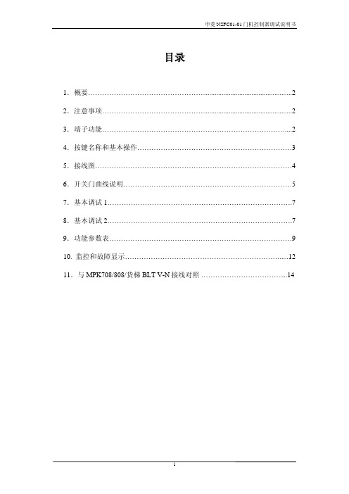
目录1.概要 (2)2.注意事项 (2)3.端子功能 (2)4.按键名称和基本操作 (3)5.接线图 (4)6.开关门曲线说明 (5)7.基本调试1 (7)8.基本调试2 (7)9.功能参数表 (9)10. 监控和故障显示 (12)11.与MPK708/808/货梯BLT V-N接线对照 (14)1、概要为适应宁波申菱新推出NSFC01-01型门机控制器的使用要求,编写本调试说明书。
NSFC01-01型门机控制器是结合门机的机械结构和门机用户控制功能的特点,委托松下电工开发的新一代门机专用型变频调速系统。
它通过编码器反馈的信息进行闭环控制,具有优良的调速特性,启动力矩大,动态响应快,齐全的专用保护和状态监视功能,并具有调试简单、运行平稳可靠、噪音低等特点。
2、注意事项1 必须由具有专业资格的人员才能对控制器进行调试、维修或检查。
2 确认输入电源处于完全断开的情况下,才能进行配线作业。
3 不要把输入端子(L,N)与输出端子(U,V,W) 混淆,否则会损坏控制器。
4 将控制器的接线地端子可靠接地,否则有触电危险。
5 通电情况下,不要用手触摸控制端子,否则有触电危险。
6 在充电指示灯彻底熄灭或正负母线电压在36V 以下时进行否则有触电 的危险。
7 防止螺钉,垫片及金属之类的异物掉进变频器内部否则有火灾及损坏财务的危险。
8 主回路接线用电缆端头的裸露部分,一定要用绝缘胶带包扎好否则有损 坏财物的危险。
3、端子功能端子名称 电缆线号(颜色)端子功能说明 L / N / 接地 褐色/兰色/黄绿 单相交流电源输入端子U / V / W U/V/W 电机接线端子1 2# 开门命令常开输入(NO )2 3# 关门命令常开输入(NO )3 --* 开门限位常闭输入(NC )4 --* 关门限位常闭输入(NC )8 1# 开关门输入公共端(COM )9 红色 电源 +12VDC10 兰色 编码器 A 相11 绿色 编码器 B 相12 黑色 电源 0VDCC2-C3 4# 到位输出公共端B2 5# 开门到位常闭输出(NC )B3 6# 关门到位常闭输出(NC )C1 故障 输出公共端(COM )B1 故障 常闭输出(NC )A1 备用 故障 常开输出(NO )注: --*为控制器内部接线不在6芯控制电缆线内4、按键名称和基本操作4、1 按键名称4、2 按键基本操作以改变参数P05为22为例:按键次序显示内容注:参数d 在参数p之后。
宁波申菱门机说明书正文编码器2004-02

目录1.产品概要 (1)2.注意事项 (1)3.端子功能 (1)4.按键名称和基本操作 (2)5.接线图 (3)6.开关门曲线说明 (4)7.基本调试1 (6)8.基本调试2 (6)9.功能参数表 (8)10. 监控和故障显示 (11)1、产品概要感谢使用宁波申菱NSFC01-01型门机控制器,使用前请仔细阅读本使用手册NSFC01-01型门机控制器是我们公司根据市场需要,结合公司门机的机械结构和门机用户控制功能的特点,委托松下电工开发的新一代门机专用型变频调速系统。
它通过编码器反馈的信息进行闭环控制,具有优良的调速特性,启动力矩大,动态响应快,齐全的专用保护和状态监视功能,并具有调试简单、运行平稳可靠、噪音低等特点。
2、注意事项1 必须由具有专业资格的人员才能对控制器进行调试、维修或检查。
2 确认输入电源处于完全断开的情况下,才能进行配线作业。
3 不要把输入端子(L,N)与输出端子(U,V,W) 混淆,否则会损坏控制器。
4 将控制器的接线地端子可靠接地,否则有触电危险。
5 通电情况下,不要用手触摸控制端子,否则有触电危险。
6 在充电指示灯彻底熄灭或正负母线电压在36V以下时进行否则有触电的危险。
7 防止螺钉,垫片及金属之类的异物掉进变频器内部否则有火灾及损坏财务的危险。
8 主回路接线用电缆端头的裸露部分,一定要用绝缘胶带包扎好否则有损坏财物的危险。
注: --*为控制器内部接线不在6芯控制电缆线内,在门机出厂时已连接好。
4、按键名称和基本操作4、1 按键名称4、2 按键基本操作以改变参数P05为22为例:注:参数d 在参数p 之后。
在切换到参数p可得到d 参数5、接线图注意:1.与上位机配线时,请将动力线与控制线分开走线.2.在配接开关门到位输出电缆线时,要确认门控制器输出的逻辑状态与控制柜接收的逻辑相符,门控制器的出厂状态是常闭输出.用户要根据主控制柜实际情况选择到位输出的逻辑状态.( 端子A2)--开到位常开输出,(端子A3)--关到位常开输出, (端子C2-C3 )--输出公共端6、开关门过程说明6、1 开门过程1、以力矩提升为P05、加减速时间为d28,加速到开门低速频率 P15,进入开门起始低速运行。
- 1、下载文档前请自行甄别文档内容的完整性,平台不提供额外的编辑、内容补充、找答案等附加服务。
- 2、"仅部分预览"的文档,不可在线预览部分如存在完整性等问题,可反馈申请退款(可完整预览的文档不适用该条件!)。
- 3、如文档侵犯您的权益,请联系客服反馈,我们会尽快为您处理(人工客服工作时间:9:00-18:30)。
目录1.产品概要 (1)2.注意事项 (1)3.端子功能 (1)4.按键名称和基本操作 (2)5.接线图 (3)6.开关门曲线说明 (4)7.基本调试1 (6)8.基本调试2 (6)9.功能参数表 (8)10. 监控和故障显示 (11)1、产品概要感谢使用宁波申菱NSFC01-01型门机控制器,使用前请仔细阅读本使用手册NSFC01-01型门机控制器是我们公司根据市场需要,结合公司门机的机械结构和门机用户控制功能的特点,委托松下电工开发的新一代门机专用型变频调速系统。
它通过编码器反馈的信息进行闭环控制,具有优良的调速特性,启动力矩大,动态响应快,齐全的专用保护和状态监视功能,并具有调试简单、运行平稳可靠、噪音低等特点。
2、注意事项1 必须由具有专业资格的人员才能对控制器进行调试、维修或检查。
2 确认输入电源处于完全断开的情况下,才能进行配线作业。
3 不要把输入端子(L,N)与输出端子(U,V,W) 混淆,否则会损坏控制器。
4 将控制器的接线地端子可靠接地,否则有触电危险。
5 通电情况下,不要用手触摸控制端子,否则有触电危险。
6 在充电指示灯彻底熄灭或正负母线电压在36V以下时进行否则有触电的危险。
7 防止螺钉,垫片及金属之类的异物掉进变频器内部否则有火灾及损坏财务的危险。
8 主回路接线用电缆端头的裸露部分,一定要用绝缘胶带包扎好否则有损坏财物的危险。
注: 1、--*为控制器内部接线不在6芯控制电缆线内,在门机出厂时已连接好。
2、控制端子第1~7号端子请连接无电压接电信号或开路集电极信号。
信号端电压为+12VDC ,输入公共端8为负。
4、按键名称和基本操作 4、1 按键名称4、2 按键基本操作以改变参数P05为22为例:注:参数d 在参数p 之后。
在切换到参数p可得到d 参数5、接线图注意:1.与上位机配线时,请将动力线与控制线分开走线.2.在配接开关门到位输出电缆线时,要确认门控制器输出的逻辑状态与控制柜接收的逻辑相符,门控制器的出厂状态是常闭输出.用户要根据主控制柜实际情况选择到位输出的逻辑状态.( 端子A2)--开到位常开输出,(端子A3)--关到位常开输出, (端子C2-C3 )--输出公共端6、开关门过程说明6、1 开门过程1、以力矩提升为P05、加减速时间为d28,加速到开门低速频率 P15,进入开门起始低速运行。
2、当门位置脉冲≥d03时,开始以目标频率值为d16、加减速时间为d29,进入开门高速运行(高速段一般设置为一段,即:d16、d17、d18、d19设置为相同值)。
3、当门位置脉冲≥d07时,开始以目标频率值为d20、加减速时间为d33,进入开门结束低速运行。
4、当门位置脉冲≥d08时,开始以保持频率d21、保持电流d40进入门到位力矩保持。
注意:1、开门高速段一般设置为一段即:d16=d17=d18=d19,对应的加减的参数 d31、d32和d33将不起作用。
2、通过调节:各段的运行频率、加减速时间或门的脉冲位置点,实现开门的运行曲线。
该系统以开门到位为门位置脉冲的100%,关门到位为门位置脉冲的0%。
在改变位置点数值时,要保证数值的大小次序(比如:d06≤d07)3、开门到位保持频率为d21,保持电流为d40。
保持时间为d42,范围为0.1到999(sec),当设置为0时,则长期保持。
4、若低速段开门力矩较小,可以适当加大P05的值。
注意:过大的P05值可能会引起过流保护。
6、2 关门过程:1、以力矩提升为P05、加减速时间为d34,加速到开门低速频率 d22,进入关门起始低速运行。
2、当门位置脉冲≥d09时,开始以目标频率值为d23、加减速时间为d35,进入关门高速运行(高速段一般设置为一段,即:d23、d24、d25、d26设置为相同值)。
3、当门位置脉冲≥d13时,开始以目标频率值为d27、加减速时间为d39,进入关门结束低速运行。
4、当门位置脉冲≥d02时,开始以保持频率d14、保持电流d41进入门关到位力1、关门高速段一般设置为一段即:d23=d24=d25=d26,对应的加减的参数d36、d37和d38将不起作用。
2、必要的情况下,可不设置关门起始低速段,即将设置d22=d23(高速频率值)同时应增大d34(d34=1.2左右)减小d09(d09=75左右)以保证运行曲线平稳3、通过调节:各段的运行频率、加减速时间或门的脉冲位置点,实现关门的运行曲线。
该系统以开门到位为门位置脉冲的100%,关门到位为门位置脉冲的0%。
在改变位置点数值时,要保证数值的大小次序(比如:d13≤d12)4、关门到位保持频率为d14,保持电流为d41。
保持时间为d42,范围为0.1到999(sec),当设置为0时,则长期保持。
5、关门过程中当有卡门阻力大于设定值(过载)时,执行开门。
设定参数为:p64(低速区)、p65(高速区)、高低速区的分界频率参数p66。
参数p64、p65的设定越大,执行开门的卡门阻力越小。
6、若低速段关门力矩较小,可以适当加大P05的值。
注意:过大的P05值可能会引起过流保护。
7、基本调试1门机出厂前已经完成门宽自学习和功能参数的设置。
根据需要,用户可以对照开关门运行曲线图和对应的参数,调节开关门的运行曲线。
1、设置控制方式为面板键盘方式:p08=1。
2、对照开关门运行曲线图和对应的参数(第4、5页),调节开关门运行曲线3、按RUN键,以下相同操作)查看开/关门的运行曲线。
4、设置控制方式为端子控制方式:p08=2(出厂设置)。
注意:如果控制器在运行(即有频率输出)中,参数p08(功能参数表中属于R 编辑)将不能被修改。
请按“STOP”键后,再按切换“MODE”键到p参数栏进行参数p08参数值的修改。
8、基本调试2在更换电机、编码器、到位开关逻辑(NO/NC)或重新进行门宽自学习时请确认以下步骤:8、1 输入输出信号监控(参数n16、参数n17)的确认参数n16为输入信号的监控包括: ①~⑨信号灯。
参数n17为输出信号的监控包括:开限位输出、关限位输出、故障输出。
①-----开门指令信号 / 故障输出信号②-----关门指令信号 / 开限位输出信号③-----开到达信号 / 关限位输出信号④-----关到达信号⑤-----光幕/触板信号⑥-----开变速信号⑦-----关变速信号注意:监视信号⑤、⑥、⑦出厂时⑧-----编码器A相未定义,此处不予以监控。
B相按n 参数模式,键得到对应的监控参数8、2 输入端子的逻辑(NO/NC)设定的确认输入信号逻辑设定参数---P431、设定值: 0----信号端子与输入公共端闭合时,此时该信号有效(NO)。
1----信号端子与输入公共端断开时,此时该信号有效(NC)。
2、设定方法:0—15bit 的10进制数输入设定值⨯权=合计值(作为设定值)例如:开到达输入信号、关到达输入信号设置为:NC ;其他为:NO1、输入信号的确认条件:P08=1;P09=1步骤:通过参数n16模拟监视以下输入状态1、开/关指令信号2、手动移动门使开(关)到位,确认开(关)到位信号3、编码器A/B相输入信号的闪烁确认通过参数n11监控编码器A/B相正确a.门向开方向移动,确认是否显示“F**”b.门向关方向移动,确认是否显示“r**”2、电机的正、反转的确认条件:设定频率(Fr模式下)为3Hz左右。
设定P08=1,P09=0键,确认开动作;键,确认关动作。
注:若电机不动作时,适当增大P05(力矩提升)值。
若电机运转方向不正确,改变输出相序。
3、自学习条件:设定P08=1;P09=3;P63=0;P67=0步骤:1P52=512出厂标准)、电机极数(P51=6出厂标准)2、按键直到出现“CAL”,再将门拉开到中间左右位置2键,自学习开始,正常时门先关门后开门到位3、自学习结束时,显示“End”.(门宽脉冲数自动保存于d01中)4、按“STOP”键,执行复位操作。
(“End”---“000”)复位后,参数P09自动置1。
5键和键观察是否正常开关门。
6、恢复P08、P63、P67的出厂值(P08=2,P63=0,P67=300)。
注:自学习过程中,门不动作或动作缓慢,可以调节自学习频率d52参数,复位后,若有开/关指令信号,马上自动执行。
4、开关门曲线调节:按基本调试1 进行开关门曲线调节。
若忘记过多已修改的参数,用户可进行参数初始化,具体步骤如下: 1、进行参数初始化:将参数P42=1。
2 、按功能参数表输入带阴影部分参数的数值。
3 、进行门宽自学习 (按基本调试2进行)。
附注:设定完各参数的数据后,为了防止不小心改变数据,可以设定密码。
参数p41:全区密码(P 参数区域,d 参数区域)的参数设定密码。
设定范围:000; 1~999 (设定为:“000”时表示不设定密码)。
设定密码后参数数据的变更步骤: 以参数p41的密码设定为“777”为例1、按“STOP ”键,使电梯门控制器停止运行。
2、按4次“MODE ”键,变为密码输入显示(PS ),显示闪烁。
3(显示闪烁) 4、 按“SET ”键,显示出参数号(上一次的参数号:比如P01等)(出厂未作密码设定,若进行密码设定,请务必记录密码,以防忘记!)。
