迅达APMMR现场安装手册
(整理)迅达 300C MMR调试手册
迅达300C MMR调试手册目录1 安全32 准备工作 (4)3 Mic-SE32A-0110控制板 (5)3-1 Mic-SE32A-0110控制板概貌 (5)3-2 Mic-SE32A-0110控制板端口说明 (5)4 SM-02-C轿厢板和SM-03-B指令板 (9)4-1 SM-02-C轿厢板和SM-03-B指令板概貌 (9)4-2 SM-02-C轿厢板端口说明 (9)4-3 SM-03-B指令板端口说明 (11)4-4 SCOP-SCON-0410轿内显示板概貌 (11)4-5 SCOP-SCON-0410轿内显示板端口说明......... (12)5 SLOP-SCON-0410 厅外显示板 (13)5-1 SLOP-SCON-0410 厅外显示板概貌 (13)5-2 SLOP-SCON-0410 厅外显示板端口说明 (13)6 SMLCD (15)6-1 概述 (15)6-2 操作说明 (15)7 变频器自学习 (16)3-1短接线 (17)3-2通电 (17)3-3设置曳引机参数 (17)3-4确认电机运转方向 (17)3-5自学习 (18)3-6自学习故障以及对策 (18)8 安装运行 (20)8-1机房 (20)8-2通电 (21)9 快车调试 (22)9-1准备工作 (22)9-2通电 (22)10 电梯舒适感调整 (25)10-1 电梯载荷控制仪 (25)10-2 起动力矩补偿 (27)10-3舒适感整体调整 (29)11 电梯参数表和故障代码表 (29)11-1电梯参数表 (29)11-2 电梯参数详细说明 (33)11-3 电梯故障代码表 (43)12 变频器参数 (46)13 变频器部分代码简述及对策 (49)1 安全安全要求安装现场应按安全操作规程要求配置相应的安全防护设备。
所有安装人员应按要求正确使用安全防护设备及设施。
图1. 安全设备1 安全帽2 防护眼镜3 安全带4 防护鞋5 防护手套·在工地和井道安装合适的照明设备。
安科瑞 APM 系列网络电力仪表 安装使用说明书
217APM系列网络电力仪表安装使用说明书V2.0申明版权所有,未经本公司之书面许可,此手册中任何段落、章节内容均不得被摘抄、拷贝或以任何形式复制、传播,否则一切后果由违者自负。
本公司保留一切法律权利。
本公司保留对本手册所描述之产品规格进行修改的权利,恕不另行通知。
订货前,请垂询当地代理商以获悉本产品的最新规格。
目录1.概述 (1)2.产品规格 (1)3.技术参数 (2)4.安装接线说明 (4)4.1安装尺寸 (4)4.2接线方法 (4)5.包装 (6)6.工程施工注意事项 (6)6.1电压输入 (6)6.2电流输入 (7)6.3通讯接线 (7)7.操作说明 (7)7.1显示说明 (7)7.2面板说明 (9)7.3显示总览 (9)测量参数 (12)7.4系统设置 (21)7.5重置数据 (29)8.Modbus通讯说明 (29)8.1简介 (29)8.2通讯地址表 (30)8.3通讯值与实际值对应关系 (43)9.以太网通讯指南 (47)9.1以太网参数修改 (47)9.2扩展RS485通讯 (48)10.复费率说明 (50)10.1复费率电能查看 (50)10.2复费率设置 (51)10.3复费率电能通讯地址表 (52)11.DL/T-645通讯指南 (56)11.1DL/T645-2007协议简述 (56)11.2传输方式 (56)11.3协议 (56)12.Profibus-DP (63)12.1Profibus-DP协议概述 (63)12.2Profibus通讯功能配置 (65)13.常见故障分析 (70)1.概述安科瑞电气APM系列网络电力仪表是按IEC标准设计,与国际先进技术同步的网络电力仪表。
具有全电量测量,电能统计,电能质量分析及网络通讯等功能,主要用于对电网供电质量的综合监控。
该系列仪表采用了模块化设计,配合功能丰富的外部DI/DO模块、AI/AO模块、Micro SD卡(TF卡)事件记录(SOE)模块、网络通讯模块、温湿度测温模块,可以灵活实现电气回路全电量测量及开关状态监控,双RS485和以太网接口配合可实现RS485主站数据抄送,省去数据交换机。
300C MMR调试说明书
2/51
迅达中国
1 安全
安全要求
调试手册 300C MMR
安装现场应按安全操作规程要求配置相应的安全防护设备。 所有安装人员应按要求 正确使用安全防护设备及设施。
图1. 安全设备
1 安全帽 2 防护眼镜 3 安全带 4 防护鞋 5 防护手套
• 在工地和井道安装合适的照明设备。 • 应立即更换或补充被损坏或丢失的安全装备。 • 如果有坠落的风险,应扣好安全带和安全帽。 • 正确使用并妥善保管工具。 • 遵守安装工具及设备制造厂的使用说明。 • 所有安装人员应对自己的安全及健康负责。
5 SLOP-SCON-0410 厅外显示板 ............................................................ 13 5-1 SLOP-SCON-0410 厅外显示板概貌 ............................................ 13 5-2 SLOP-SCON-0410 厅外显示板端口说明 .......................................... 13
l JP1.1
输入 X0,检修信号,断开为检修,闭合为自动
l JP1.2
输入 X1,上行信号. 在检修时闭合为点动上行,在司机时闭合
为上行换向
l JP1.3
输入 X2,下行信号. 在检修时闭合为点动下行,在司机时闭合
为下行换向
l JP1.4
输入 X3 上行第二终端换速开关, 超过 1 米/秒 以上电梯要求
调试手册 300C MMR
序号 步骤
备注
l JP1.10
输入 X9,上平层开关
l JP2.1
迅达(中国)安装及调试组织方案
安装及调试组织方案施工方案及组织计划1、安装方法说明1.安装进度当我们在接受总承包商的施工计划时,我们将为每台电梯准备安装进度表。
我们将根据总承包商的施工计划细节计算出精确的人力配置和设备进场时间。
这些进度表将响应总承包商的施工计划的修改而有计划地修改。
我们将及时把安装进度向总承包商和日立电梯现场经营部汇报。
2.制造进度我们将根据交货期和现场安装的进度,并有必要的话根据现场情况的变化而变化,以确保元件制造、采购与施工计划匹配。
3.运输/储藏我们将协助甲方协调运输及货物的储藏工作。
4.安装程序当电梯的机房和井道测量完毕,并符合我们的要求时,电梯安装才可开始;电梯安装将从导轨和井道、地坑的设备开始,然后才是门套、厅门;曳引机和控制屏将被吊到并固定在机房内;电梯轿厢将在井道内拼装,然后是对重。
在电梯转交给调试工程师进行最后测试、调试之前,曳引绳、机房、电线等都将完毕。
5.质量参与该项目的所有公司都将遵循ISO9001质量管理体系,包括产品设计、制造、安装和维修保养。
工程概况:工程名称:工程地点:二、电梯概况:1.电梯种类:2.台数:三、施工组织整个施工过程分为四个阶段第一阶段:完成电梯零部件安装;第二阶段:功能调试,电梯安装全部完毕;第三阶段:5000次无故障运行,整理资料;第四阶段:政府部门验收,向甲方移交。
工程安排勘查工作现场,准备卸货现场;进货起吊:总包单位应指定卸车地点,给足使用场地;按甲乙双方确认的电梯土建图勘查电梯井道、机房,是否符合图纸要求;机房门窗是否齐全贯通井道有无隔梁井道结构是否影响电梯安装底坑、机房异物清除楼层有无标高线厅门洞口尺寸是否合格如果井道误差超标,与甲方土建和设计配合提出整改方案。
查看脚手架搭设是否符合国家安全规范标准。
施工前的准备工作:施工前需甲方配合的工作按时提供施工用电和电梯正式电源,临电需提供二级闸箱,指定专用空开,闸箱应位于机房附近,空开容量为60A(根据需要);提供电梯的进货通道,提供垂直运输的方便;库房的落实是电梯工程能否开箱点件的必备条件之一,也是整个电梯工程能否顺利完工的必备条件之一。
迅达操作标准手册样本

迅达3300AP无机房3300AP(rel.4版本),有四个按钮,分别是“ESC ↓↑OK”,四个键。
查故障:1、在原则显示状态下,按OK一次,显示"10"2、按↑键4次,显示"50"3、按OK键,显示"50 0"4、按↑键,显示"50 1"5、按0K键,就能查看近来旳故障代码;按↓键,直到显示"E0****",再按↓显示"E1****",依次类推。
E0表达最新旳故障。
6、清除故障措施:在显示"e*****"时,始终按住OK键约3秒,显示“-------",阐明清除故障成功。
限速器实验(刹车实验),注意:如下环节前,先将107改为1(关闭称重),机房检修盒插上。
1、1、在原则显示状态下,按OK一次,显示102、按↑键一次,显示"20 0"3、按↑键一次,显示"20 1"4、按OK键5、显示”20 --",同步电梯跑到最顶层,开门后,6、按↑键直到显示"20 75",按OK键,同步显示"75 1"7、门开始关闭,之后显示"75 2"8、打机房检修,并按”下行键“,待电梯蜂鸣器长响后,按DBV键,刹车。
如果成功会显示"75 1"9、按ok键确认,显示"20 1",按↑键,显示"20 0",按OK键,显示”20“,再按"esc"退回返回主菜单。
10、刹车完后,机房检修拉起轿厢,(如果实在拉不起来,就搬走一部分砝码)11、最后,限速器开关复位操作:在主菜单上按"ok"键一次,显示"10",按OK键一次,显示"101",在按↑键直到显示125,按OK键一次,显示"125 0",按↑键一次,显示"125 1",按OK键一次,限速器开关就复位。
终端现场安装调试手册实用版

终端现场安装调试一安装前准备工作:1.专用工具准备安装过程中,需要使用以下工具:万用表,手枪电钻,老虎钳,斜口钳,铅封钳,铅封头和封线,钢卷尺,大号螺丝刀(十字、一字各一),小号螺丝刀(十字、一字各一),绝缘胶带,接线板,带夹电源线,Φ3.5和Φ4.0的钻头,记号笔,表计遥控器等。
2.现场安装条件1、带485通讯功能的多功能电表。
2、有联合接线盒。
3、有计量柜。
4、无线信号网络较好(一般手机信号至少在1格以上)。
二.现场终端安装1、终端的固定1)按安装位置要求确定终端的上挂点。
用手钻打孔,用螺钉固定。
2)上挂终端,用记号笔点出其2个下安装孔,打孔并固定。
2、终端的接线1)安装使用的导线必需符合以下要求:a、电压回路接线采用2.5 mm2单芯硬线,电流回路接线采用2.5或4 mm2单芯硬线。
b、485线信号采用0.23mm 2的互套双绞线。
2)接线的方法a、三相四线1.打开联合接线盒的盖子,短接接线盒的电流板,断开电压板。
取A、B、C三相电压和零线直接连接到终端相对应的接线柱上,接线的工艺要求与表计相同。
2.分别断开A、B、C三相表计到接线盒电流出的电流线。
按照电流线串联到计量回路的方式(类似有功无功表的接法),把终端串到计量回路里,接线的工艺要求与表计相同。
3.电压、电流接线示意图如下:b、三相三线1.打开联合接线盒的盖子,短接接线盒的电流板,断开电压板。
取A、B、C三相电压直接连接到终端相对应的接线柱上,接线的工艺要求与表计相同。
2.分别断开A、C三相表计到接线盒电流出的电流线。
按照电流线串联到计量回路的方式(类似有功无功表的接法),把终端串到计量回路里,接线的工艺要求与表计相同。
3.电压、电流接线示意图如下:c、连接485线根据现场表计的接线说明,使用双绞线连接表计和终端之间的485接口。
即表计的485A接终端的485A(功能接线端子31孔),表计的485B接终端的485B(功能接线端子32孔),如果表计的485接口已经被其它设备占用(如负控装置),则不能再将终端和其进行连接。
迅达A 操作手册
迅达3300AP无机房3300AP(rel.4版本),有四个按钮,分别是“ESC ↓↑OK”,四个键。
查故障:1、在标准显示状态下,按OK一次,显示"10"2、按↑键4次,显示"50"3、按OK键,显示"50 0"4、按↑键,显示"50 1"5、按0K键,就能查看最近的故障代码;按↓键,直到显示"E0****",再按↓显示"E1****",依次类推。
E0表示最新的故障。
6、清除故障方法:在显示"e*****"时,一直按住OK键约3秒,显示“-------",说明清除故障成功。
限速器试验(刹车试验),注意:以下步骤前,先将107改为1(关闭称重),机房检修盒插上。
1、1、在标准显示状态下,按OK一次,显示102、按↑键一次,显示"20 0"3、按↑键一次,显示"20 1"4、按OK键5、显示”20 --",同时电梯跑到最顶层,开门后,6、按↑键直到显示"20 75",按OK键,同时显示"75 1"7、门开始关闭,之后显示"75 2"8、打机房检修,并按”下行键“,待电梯蜂鸣器长响后,按DBV键,刹车。
如果成功会显示"75 1"9、按ok键确认,显示"20 1",按↑键,显示"20 0",按OK键,显示”20“,再按"esc"退回返回主菜单。
10、刹车完后,机房检修拉起轿厢,(如果实在拉不起来,就搬走一部分砝码)11、最后,限速器开关复位操作:在主菜单上按"ok"键一次,显示"10",按OK键一次,显示"101",在按↑键直到显示125,按OK键一次,显示"125 0",按↑键一次,显示"125 1",按OK键一次,限速器开关就复位。
迅达5400AP_MMR_现场安装手册
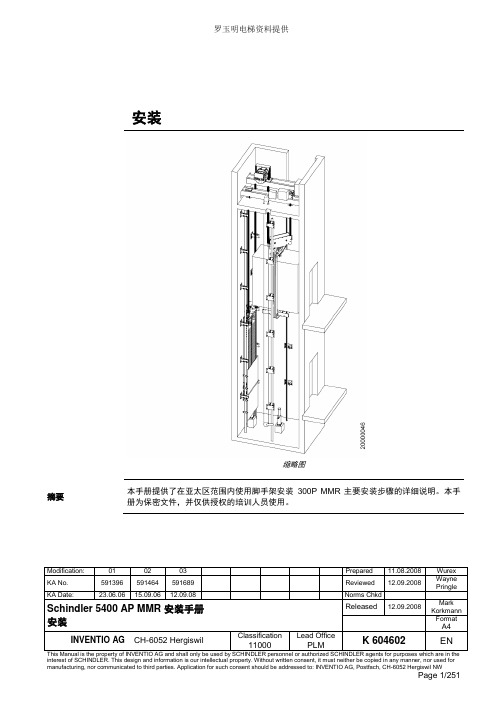
罗玉明电梯资料提供安装缩略图摘要本手册提供了在亚太区范围内使用脚手架安装300P MMR 主要安装步骤的详细说明。
本手册为保密文件,并仅供授权的培训人员使用。
目录1 安全建议 (4)1.1 概要 (4)1.2 使用符号 (4)2 先决条件 (5)2.1 产品概述 (5)2.2 安装步骤 (7)2.3 专用工具 (9)3 施工现场准备工作 (10)4 导轨安装 (15)4.1 准备工作 (15)4.2 导轨支架安装 (15)4.3 导轨安装 (21)4.3.1 导轨基座 (21)4.3.2 导轨安装 (22)4.4 连接板校正 (24)5 Varidor 30AP C2 厅门入口安装 (25)5.1 门框预安装 (27)5.2 地坎支架 (30)5.3 门框和机械横梁 (31)5.4 地坎和护脚板 (35)5.5 门板 (36)5.6 C2井道互锁装置 (40)5.7 门解锁装置 (41)5.8 安装门重锤 (42)5.9 防护罩 (44)6 PMS420无齿轮机组安装 (45)6.1 机组支架 (47)6.2 安装PMS420无齿轮机组 (48)6.3 *手动应急操作选配装置 (51)6.4 制动器调整和制动力测试 (57)6.5 *曳引钢丝绳悬挂装置安装 (58)6.6 *安装限速器 (62)7 *安装GGM2-AP对重 (71)7.1 先决条件 (71)7.2 *机械安装 (72)7.2.1 *缓冲器支撑 (72)7.2.2 *对重校正 (73)7.2.3 *安全钳(选配) (74)7.2.4 *导靴 (76)7.2.5 油杯(选配) (79)7.2.6 *对重块 (79)7.2.7 *补偿链悬挂装置 (80)7.2.8 地震传感器(选配) (81)7.3 *调整和最后检查 (82)7.4 对重防护屏 (83)7.4.1 *对重防护屏后置 (83)7.4.2 *对重防护屏侧置 (84)8 安装轿厢架FRS9-AP/FRM9-AP (87)8.1 安装轿厢架FRS9-AP (87)8.2 FRS9-AP安全钳和导靴选配件 (98)8.3 FRM9-AP安全钳和导靴选配件 (99)9 安装曳引绳 (100)9.1 处理钢丝绳 (100)9.2 安装钢丝绳 (101)9.3 钢丝绳绳头安装 (105)9.4 检查钢丝绳张紧度和绳的润滑 (109)9.5 限速器钢丝绳 (110)10 轿厢P9KD-AP(CM)安装 (117)10.1 轿厢安装步骤 (118)10.2 *安装轿厢装璜 (134)10.3 安装满载、超载开关 (143)10.4 轿厢平衡装置 (144)11 V30 AP轿门安装 (145)11.1 C2轿门 (145)11.1.1 轿门机驱动 (146)11.1.2 轿门板 (147)11.1.3 轿门刀 (149)11.2 安装光幕(MiniMax光幕LVH) (151)12 安装缓冲器 (157)13 安装补偿链 (159)13.1 补偿链导向装置 (159)13.1.1 4-滚轮导靴 (159)13.1.2 2-滚轮导靴 (162)13.2 补偿链 (165)14 安装MX-GC (170)14.1 先决条件 (170)14.2 材料范围 (171)14.3 控制柜 (172)14.4 井道信息 (174)14.4.1 井道信息IGSI (174)14.4.2 绝对值线型井道信息系统 (190)14.5 控制柜内模块 (210)14.6 机房电缆 (211)14.7 井道电缆 (215)14.7.1 准备 (220)14.7.2 安装 (223)14.7.3 调整和最后检查 (229)14.8 OKR (231)14.9 随行电缆 (236)14.9.1 带IGSI和LONCIB的MX-GC,HQ<=70m (237)14.9.2 带IGSI和LONCIB的MX-GC,HQ>70m (238)14.9.3 带IGSI和LONIC/LONICK的MX-GC,HQ<=70m (239)14.9.4 带IGSI和LONIC/LONICK的MX-GC,HQ>70m (240)14.10 控制柜内ASIXA32.Q的概述与名称 (241)15 VARIODYN VF44BR和VF88BR安装 (243)15.1 VARIODYN VF44BR安装 (243)15.2 VARIODYN VF88BR安装 (249)1 安全建议1.1 概要描述安全装备安全鞋安全帽防护眼镜全身型安全带防护手套安全要求所有参与的安装人员必须熟悉并遵守公司以及当地的安全规范,特别要注意以下几点:•照明必须充足,以保证安全生产。
美国阿尔弗雷德 APM 系列软件安装指南说明书

Software Installation Guide NOTE:Read the entire Software Installation Guide before usingthe APM for Windows software.SAFETY CONSIDERATIONSInstalling and servicing heating equipment can be hazardous due togas and electrical components.Only trained and qualified servicepersonnel should install,repair,or service heating equipment.Untrained personnel can perform basic maintenance functions suchas cleaning coils,or cleaning and replacing filters.All otheroperations should be performed by trained service personnel.When working on heating equipment,observe precautions inliterature,on tags,and on labels attached to or shipped with theunit,and other safety precautions that may apply.Follow all safety codes.In the United States,follow all safetycodes including the National Fuel Gas Code(NFGC)NFPA54/ANSI Z223.1--2006.In Canada,refer to the National Standardof Canada Natural Gas and Propane Installation Codes(NSCNGPIC),CAN/CSA149.1--05.Wear safety glasses and work gloves.Have a fire extinguisheravailable during start--up,adjustment procedures,and service calls.Recognize safety information.This is the safety--alert symbolWhen you see this symbol on the furnace and in instructions ormanuals,be alert to the potential for personal injury. Understand the signal words DANGER,WARNING,CAUTION,and NOTE.The words DANGER,WARNING,and CAUTION are used with the safety--alert symbol.DANGER identifies themost serious hazards which will result in severe personal injury or death.WARNING signifies hazards which could result in personal injury or death.CAUTION is used to identify unsafe practices which would result in minor personal injury,or product and property damage.NOTE is used to highlight suggestions which will result in enhanced installation,reliability,or operation.INTRODUCTIONThe Advanced Product Monitor--APM(Furnace Version)is asoftware package that can be used for sales demonstrations, training,and to start--up and troubleshoot Variable Speed Furnaces.APM(Furnace Version)has been tested and approved for use on furnace control boards P/N HK42FZ001,HK42FZ002, CESO130004--00,HK42FZ003,HK42FZ012,HK42FZ021, HK42FZ022,HK42FZ024,HK42FZ026,and HK42FZ031. Because the Advanced Product Monitor runs on a portable laptop PC,it can be carried anywhere to provide the service technician with local access to any Variable Speed Furnace.The Advanced Product Monitor enables a service technician to perform the following tasks:S Monitor furnace parameters.S Save furnace parameters to disk.S Data Log furnace parameters.S Force the furnace into high fire.(All Boards except P/NHK42FZ021,HK42FZ022,HK42FZ024,HK42FZ026,&HK42FZ031)S Force the furnace into low fire.(Board P/N HK42FZ003&HK42FZ012only)S Review the entire furnace fault history.S Review the recent faults in furnace fault history.S Review the last fault that occurred.(Board P/N HK42FZ003, HK42FZ012,HK42FZ021,HK42FZ022,HK42FZ024,HK42FZ026,&HK42FZ031only)S Display troubleshooting information for each fault code.S Save the furnace fault history to disk.S Clear the furnace fault history.S Review the furnace statistics.S Save the furnace statistics to disk.The Advanced Product Monitor has the following NEW capabilities:S Supports new Step--Modulating furnaces.S Supports SPP gas--fired units with ABCD User Interface Connections.S Can be spliced into any ABCD User Interface Connection point. This allows furnace troubleshooting at the outdoor unit.The Advanced Product Monitor is designed for ease of operation.It utilizes menus,special function keys,plain language prompts, and standardized screen format.If you have a PC,or are considering purchasing a PC,the following general requirements should apply:S PC using Pentium233or higher microprocessor.PCs with486 to Pentium200microprocessor’s will work but the ABCDconnector to the User Interface must be disconnected.S At least16Mb(or more)of system memory.S At least6Mb(or more)of free hard drive storage space.S3.5”floppy drive or CD--ROM drive.S Windows95,98,ME,NT,2000,XP or Vista.S RS232port.Adapter required for USB only computers.S VGA display.Included with the Advanced Product Monitor is a B&B RS485 adapter and an interface cable that will connect any of the following furnace control boards P/N HK42FZ003,HK42FZ012, HK42FZ021,HK42FZ022,HK42FZ024,HK42FZ026,& HK42FZ031to a PC.This cable has3stripped and tinned leads on one end and three separate connections on the other end.The stripped leads connect to the B&B RS485adapter.The WHITE housing connects to furnace control P/N HK42FZ003or HK42FZ012at the3--pin communication connector PL--6.The GREEN ABCD PLUG housing connects to furnace control HK42FZ021,HK42FZ022,HK42FZ024,HK42FZ026or HK42FZ031at the4--pin ABCD connector PL7.The GREEN ABCD RECEPTACLE housing in combination with the GREEN ABCD PLUG housing allows you to splice in the APM at any ABCD User Interface connection point except for the one at the User Interface.This allows you to check the furnace from the outdoor unit.NOTE:You will need an APM adapter harness to connect the interface cable to first generation furnace control boards P/N HK42FZ001,HK42FZ002,or CESO130004.These adapter harnesses were distributed years ago and are no longer available. This installation guide has the following sections:I.INSTALL RS232/485ADAPTERII.INSTALLING APM SOFTWAREIII.CONNECTING FURNACE TO PCIV.RUNNING APMV.PALM PILOT APM VERSIONVI.WINDOWS MOBILE5APM VERSIONI.INSTALL RS232/485ADAPTERIn order to interface the Advanced Product Monitor to the variable speed furnace a B&B RS485adapter(B&B485SD9TB)is supplied in the APM kit.ing the B&B converterPlug the B&B RS485adapter into the serial port of your PC. NOTE:If your PC has a25pin connector,an DB25F--DB9M adapter will be required.This standard adapter is available online or at some retail outlets.NOTE:If your PC has only USB connections,a USB to RS--232 adapter will be required.These adapters are available online or at most retail outlets that also sell computers.Reference Appendix A in the APM manual installed on the CD for a list of websites that have compatible adapters.The APM manual is located in the Manual folder.You will need to install the USB serial driver that comes with your USB to RS--232adapter prior to hardware installation.The B&B RS485adapter has a terminal block with5terminals. You will need to connect the interface cable to the terminal block on the B&B RS485adapter.Follow the instructions below to connect the interface cable to the B&B RS485adapter terminal block.(See Fig.1).1.Insert the BLACK wire into the terminal labeled TD(A)onthe B&B RS485adapter and tighten the screw.2.Insert the GREEN wire into the terminal labeled TD(B)onthe B&B RS485adapter and tighten the screw.3.Insert the WHITE wire into the terminal labeled GND onthe B&B RS485adapter and tighten the screw.4.Route wire tie through holes in circuit board portion ofB&B RS485adapter and tighten around cable to providestrain relief.NOTE:The terminals labeled GND and+12V are generally not used because most PCs supply power to the serial port.In the event your PC does not supply power to the serial port you will need to supply external power to the B&B RS485adapter using a12VDC power supply or a9volt transistor battery.II.INSTALLING APM SOFTWAREIn the instructions that follow,it is assumed that the E:drive letter corresponds to the computer’s CD--ROM drive and that the A: drive letter corresponds to the computer’s floppy drive.If this is not the case,please modify the instructions accordingly for your computer’s drive letters.B.Creating Floppy Disk Install SetIf you are installing the APM software onto a computer that does not have a CD--ROM drive,you must first create the floppy disk images.The APM CD--ROM contains compressed self--extracting floppy disk images of the APM install program that need to be copied to4blank,IBM formatted,1.44Mb,3.5”floppy disks.In order to create the floppy disk images,you will need to use a computer that has both a CD--ROM drive and a floppy disk drive. To create the floppy disk images and extract them to the target computer’s hard drive,follow these steps:1.Start windows and insert the APM CD into your CD--ROMdrive.The APM installation routine should automaticallylaunch.Click Cancel to stop the installation.2.Click on the Start button at the bottom left corner and se-lect Run...from the resulting menu.Type E:\mkfloppy A:E:in the text field of the resulting Run dialog then click theOK button.3.When prompted,insert a blank,IBM--formatted,1.44Mbfloppy disk into the computer’s floppy drive and press theEnter key.When the copy has completed,eject the floppydisk and label it APM Disk1of4.4.Insert another blank,IBM--formatted,1.44Mb floppy diskinto the computer’s floppy drive and press the Enter key.When the copy has completed,eject the floppy disk and la-bel it APM Disk2of4.5.Repeat this methodology until all4disk images are created.6.To extract these files to a computer without a CD--ROMdrive insert APM Disk1of4into the A:drive and click onthe Start button at the bottom left corner and select Run...from the resulting menu.Type A:\apm.exe in the text fieldof the resulting Run dialog then click the OK button.Thesefiles will be extracted to a temporary folder namedC:\apmtemp.7.When prompted insert each APM disk until all the com-pressed files are extracted.C.Installing APMBefore you can run the APM program,you must install it.If your computer does not have a CD--ROM drive,you need to create floppy disk images and extract them to the target computer’s hard drive by following the instructions in the previous section.The following instructions apply whether you are installing from the CD--ROM or the extracted files loaded on a computer’s hard drive using floppy disk images.To install the APM software follow these steps:1.Start windows and insert the APM CD into your CD--ROMdrive.The APM installation routine should automaticallylaunch.If it does not automatically launch click on the Startbutton at the bottom left corner and select Run...from theresulting menu.Type E:\setup in the text field of theresult-ing Run dialog then click the OK button.If your computer does not have a CD--ROM and you ex-tracted the floppy disk images to computer’s hard drive thenclick on the Start button at the bottom left corner and selectRun...from the resulting menu.Type C:\apmtemp\setupin the text field of the resulting Run dialog then click theOK button.2.Click Next and follow the on--screen instructions.3.Choose a destination location for the software.The setupprogram will automatically install the APM program in thefolder shown in the window,or you may select anotherfolder.Make your selection and click Next.NOTE:When installing in Windows Vista change the default folder to C:\APM\.Windows Vista prevents programs from writing to any file located in the Program Files folder.If the APM program is installed in the default folder the APM program will not be able to data log or save any views to file.In addition you will have to select the proper COM port every time the APM program is started.4.If you would like to change any selections click on the<Back button,otherwise click on the Install button.5.Once the installation is complete,click on the Finish but-ton.6.Upon successful completion,the installation program willput two new icons on the e the APM icon tolaunch the APM application.The APM Output Files foldericon is the location in which any files created by the APMapplication are stored.III.CONNECTING FURNACE TO PCThe interface cable is connected between the furnace control and the B&B RS485adapter as shown in Fig.1.The GREEN ABCD PLUG housing connects to furnace control HK42FZ021, HK42FZ022,HK42FZ024,or HK42FZ026at the4--pin ABCD connector PL7.The GREEN ABCD RECEPTACLE housing in combination with the GREEN ABCD PLUG housing allows you to splice in the APM at any ABCD User Interface connection point except for the one at the User Interface.The WHITE housing is an alternate connector that connects to furnace control P/N HK42FZ003or HK42FZ012at the3pin communication connector PL6.NOTE:You will need an APM adapter harness to connect the interface cable to first generation furnace control boards P/N HK42FZ001,HK42FZ002,or CESO130004.These adapter harnesses were distributed years ago and are no longer available. The following steps should be performed when connecting the inter-face cable and B&B RS485adapter between the furnace control P/N HK42FZ021,HK42FZ022,HK42FZ024,or HK42FZ026and PC:1.Turn off power at main disconnect.2.Remove access doors.3.Route the interface cable to the furnace control.4.Connect GREEN ABCD PLUG housing on the interfacecable to the furnace board4--pin ABCD connector PL7justbehind the model plug on the lower left side of the furnaceboard.See Fig.1for location.If a User Interface connectionis currently connected to the4--pin ABCD connector PL7disconnect it and plug it into the GREEN ABCDRECEPTACLE housing on the interface cable and thenconnect the GREEN ABCD PLUG housing on the interfacecable to the furnace board4--pin ABCD connector PL7.5.Reinstall access panel and door.6.Connect the opposite end of the furnace cable to the B&Bconverter as shown in Fig.1.7.Turn on electrical power and wait10seconds before run-ning the APM software.CONNECT TO COMPUTER SERIAL PORTB&B RS485 ADAPTER485SD9TBD A08241Fig.1--Furnace ControlIV.RUNNING APMThis section gives you a quick tour of the Advanced Product Monitor so you can start using it right away.To run the Advanced Product Monitor follow these steps:1.Start windows.2.Double--click on the icon labeled APM on your desktop.3.If everything is connected properly the computer willprompt you to enter the serial number of the unit(1to10characters)and click the OK button.NOTE:It may take as long as30seconds before the computer prompts you to enter the serial number.When prompted at least one character must be entered.In addition a name can be given instead of a serial number.See the example shown in Fig.2,where ”thisunit”isentered:A08242 Fig.2--Serial Number ExampleIf the screen shown in Fig.3appears,check your wiring,connector orientation,and whether the board is powered.If OK change your COM port because your PC may already be using COM1for a modem.If you are still having problems you may need to power the RS485adapter.Refer to the last NOTE in SectionI.A08243 Fig.3--Communications Failure Dialog4.After entering the serial number the screen shown in Fig.4should appear when using furnace control board P/NHK42FZ021,HK42FZ022,HK42FZ024,or HK42FZ026.Similar screens will appear with oldercontrols.A08244Fig.4--Screen Image—To monitor the system,click on the System Status tab.—To review the furnace fault codes and error messages,click on the Fault History tab.—To review the furnace statistics,click on the Statisticstab.—To exit the program,select File |Exit from the menu bar.NOTE :To take full advantage of the APM software features,please refer to the APM manual installed on the CD.It is located in the Manual folder.V .PALM PILOT APM VERSIONIncluded on the APM for Windows CD is a Palm Pilot version of the plete instructions are located in the palmAPM folder.VI.WINDOWS MOBILE 5APM VERSIONIncluded on the APM for Windows CD is a Windows Mobile 5version of the plete instructions are located in the winmobileAPM folder.Copyright 2010CAC /BDP D 7310W.Morris St.D Indianapolis,IN 46231Printed in U.S.A.Edition Date:09/10Manufacturer reserves the right tochange,at any time,specifications and designs without notice and without obligations.Catalog No:IIKKGASD0301APM002Replaces:IIKKGASD0301APM001。
迅达门自动门维修手册说明书

Important warranty, user informationand service record for your automatic doorAutomatic sliding door operating & maintenance manualFor power-operated doors to EN 16005AUTOMATIC SLIDING DOOR LOG BOOKContentsService and maintenanceService and maintenance Warranty statement Door system dataReport for initial inspection User guideFirst entry last exit procedure (if fitted)Daily ChecksRegular inspection and maintenance Inspection reports23456-7 891011-15Why the necessity?All doors, whether manual or automatic, are complex components subject to punishing wear and tear. Therefore to ensure that they continue to functionproperly, regular service and maintenance is imperative.Regular door maintenance helps prevent accidents, reduces breakdowns and the accompanying inconvenience, and prolongs the life of the door operator.There are also legal implications regarding the servicing of all door types which must be adhered to, to ensure the safety of users at all times. All safety requirements for power operated doors are stipulated in EN 16005:2012 Power operated pedestrian doorsets -Safety in use. All dormakaba service engineers are trained to comply with this standard through the Automatic Door Suppliers Association (ADSA) examination of competency.dormakaba provides a tailored, local resource for the servicing and maintenance of all brands of:• automatic swing• sliding and revolving doors • manual doors • fire doors• access control systems • industrial doors • roller shutters • gates & barriersFor more information visit AUTOMATIC SLIDING DOOR LOG BOOKWarranty statementService and maintenancePlease note the legal implications regarding the installation and servicing of automatic doors which must be adhered to, so as to ensure the safety of users at all times as stipulated in EN 16005:2012 Power operated pedestrian doorsets – Safety in use.Product registrationAny decision to register your product does not affect your statutory rights under the UK Sale of Goods Act 1979.If you would like to register your product with dormakaba please visit Alternatively, you can contact the dormakaba UK Service Hotline on:0800 212 380************************LimitationsThis warranty does not apply to defects resulting from Customer actions, such as mishandling, improper installation, operation outside of design limits, misapplication, attempted repair, or unauthorized modification.Any additional warranty provided by the selling agent does not imply or transfer any additional obligation to dormakaba regarding this product.dormakaba standard terms and conditions will apply at all times and are available on request.dormakaba are not liable for the consequences of any third party claim on its products, which are sold in the knowledge that installation is carried out by competent staff and maintained in accordance with current safety standards.Thank you for purchasing a dormakaba product which has been designed and manufactured to provide many year’s problem-free operation.All products sold by Dorma UK Ltd are warranted against defect in materials and workmanship for a period of 12 months from the date of purchase on a return to factory basis.If you believe this product has a defect or has failed during normal use within the warranty period, please contact the authorised agent from whom you bought the product and who will make arrangements for its return.Alternatively, if your product was installed bydormakaba please contact us directly as detailed below to discuss the return of the unit, with the product serial number. dormakaba standard terms and conditions will apply at all times and are available on request.AUTOMATIC SLIDING DOOR LOG BOOKDoor system dataTo be completed by a qualified technician at installation Manufacturer: DORMA UK Ltd, Wilbury Way, Hitchin, SG4 0AB Type of operator/door: Sliding DoorTo be completed by a qualified technician at installationProduct name: ES200 / BST / CS80 MAGNEO / Other (please state below):(delete as applicable)..........................................................................................................................................................................Sales Order No.: ..................................................................................................................................................................................Asset No.: .............................................................................................................................................................................................Year of mission date: ..............................................................................................................................................................................Installed by: DORMA UK Ltd / Other (please state company)Doorset location / reference: ............................................................................................................................................................Additional information:................................................................................................................................................................................................................................................................................................................................................................................................................................................................................................................................................................................................................................................................................................................................................................................................................................................................................................................................................................................................................................................................................................................................................................................................................................................................................................................................................................................................................................................................................................................................................................................................................................................................................................................................In order that an automatic door operator may comply with the requirements of EN16005:2012 a risk assessment should be carried out prior to installation which assesses the risk to users. It is the responsibility of the installer to ensure that a door system is compliant.AUTOMATIC SLIDING DOOR LOG BOOKReport for initial inspectionTo be completed by a qualified technician at installationThe following list of components and functions to be inspected is only a reference and shall help the inspector during inspection. From case to case, the inspection can be more or less comprehensive. In principle, the inspector has to perform a visual inspection and functional tests to check the system for completeness. In addition, the system status and the efficiency of the components and the respective safety equipment require inspection. Please consider the separate inspection instructions supplied with the individual door types.3.1 General•Functionality of door system •Proper mounting •Connections/Power supply •Guide rails and base sections •Force transmission/Incremental encoder •Bearings•Glazing, Cover•Coating, Corrosion protection•All documentation complete3.2 Check safety equipment accordingto risk assessment to EN 16005 •Finger protection (crushing, shearing and drawing in)•Safety sensors/Sensor monitoring •Reversing/Stop equipment •Safety screen•Safety contact strips (SCS) •Force limitation•Emergency pushbuttons• Safety sensors• Fire alarm connection• Batteries 3.3 Control elements •Pushbuttons/switches •Contact mats•Radio controls/Remote controls •Card readers•Motion detectors3.4 Function•Friction clutch•NC contact (limit switch) •NO contact (limit switch) •Locking device, Deactivation •Deactivation of safety equipment •Emergency manual operation •Emergency Opening/Rubber cord/ Auxiliary drive3.5 Check door system for properfunctioning in all operation modes •OFF•AUTOMATIC •PERMANENT OPEN •PARTIAL OPEN•EXIT ONLY•LOCKING DEVICESUser guide123Program switch settings:AUTOMATIC SLIDING DOOR LOG BOOKThe unit is switched off. In the case of units with theoptional locking mechanism, the door is electro-mechanically locked.Door may be opened using first entry - last exit switches if fitted.If a person or object comes within range of the radar detectors, the door opens to full opening width and closes at the end of the preset hold-open time.The external sensor is deactivated, the door may only be used from the inside (e.g. one way function on close of business).If a person or object comes within range of the internal sensor, presence sensors or light barriers, the dooropens to its full opening width and closes the end of the preset hold-open time.The operator can be programmed to lock or unlock in the ‘EXIT ONLY’ position by a dormakaba Service engi-neer.Old Program SwitchNew Program Switch.........4PARTIAL OPENING5PERMANENTLY OPENAUTOMATIC SLIDING DOOR LOG BOOKIf a person or object comes within range of thedetectors or presence sensor, the door opens to the preset partial opening width and closes at the end of the preset hold-open time.The opening width of the door can be adjusted individually. To do this:Close the door using the OFF switch settingSet the program switch to PERMANENTLY OPENThe door opens at low (check) speedAs soon as the door reaches the desiredpartial opening width, set the program switch to PARTIAL OPENINGThe door stops and the control unit stores the desired positionThe door commences a closing cycleThe door opens in check speed to its full opening width and remains in the position until another function is selected.In the event of power failureIf the program switch is in the AUTOMATIC position, the door will fail openIf the program switch is in the OFF position, the door will remain closed To open the door, turn the program switch to AUTOMATIC. After a short delay the door will open at reduce speed and remain open until power is restored or the program switch is turned to Off.Alternatively, if FIRST ENTRY - LAST EXIT is fitted, operate button once or key once to open the door. To close the door, operate either button or key once.This sequence can be carried out as required until power is restored.First entry last exit procedure (if fitted)The purpose of this system is to allow an opening of the door when the Program Switch is in the OFF position and the sensors are not operable.This means that people should not open or close the door MANUALLY which could result in a major failure of the operator and potentially damage components.There will be a GREEN BUTTON near to the door on the inside of the building.To EXIT the building:1. Turn the program switch to the OFF position and letthe door close (stand away from the door to ensure the sensor does not detect you).2. Set the building alarm (if you have one)3. Operate the GREEN BUTTON to open the door4. Exit and allow the door to close (stand away fromthe door to ensure the sensor does not detect you), then lock the door in the centre with the key when closed.To ENTER the building:There will be a KEY SWITCH or other access control near to the door on the outside of the building1. Unlock the door, before using the KEY SWITCH2. Operate the key switch on the outside of thebuilding, this will open the door3. Enter the building (stand away from the door toensure the sensor does not detect you), the door will then close behind you4. Turn off the building alarm (if you have one)5. Put the program switch into the required position,or leave it in the OFF position6. If required to admit staff members before openinghours, simply press the GREEN BUTTON. The doorwill open then re-close.AUTOMATIC SLIDING DOOR LOG BOOKDaily checks - facility operatorA safety check should be performed daily by the facility operator on each automatic door.ActivationWalk toward the door at a normal pace. The door should start opening before you reach a minimum of 1000mm from the door. If the door is an escape route,a minimum of 1500mm applies in the direction of escape.Repeat for the other side if the door has two-way operation.SafetyNote: In order to test the safety sensors we recommend using an approved test object measuring 200mm x 300mm x 700mm high to test the door safety as detailed in EN16005.Activate the door to open, place the test object in the threshold, move away from the threshold and verify that the door stays open.Remove the test object from threshold area, after a short time delay the door should close.For sensors covering the area of door travel, place the test object directly beneath the sensor. When activated, the door should open at reduced speed.Low Energy Sliding Doors (CS80 Magneo only)•May not be fitted with safety devices as described above•Often have manual activation devices •Travel at lower speeds with lower force•In the opening direction will stop when obstructed and continue after the obstruction is removed •In the closing direction will reverse open when obstructedGeneral Observations•Check the door area does not present tripping or slipping hazards•Check all door panels for broken/cracked glass•Check all doors have correct warning and information signs displayed•Check the position and security of screens & barriers •Check operation of manual or remote activation, or emergency stop button if fitted•Check for distractions and obstructions in the vicinity of the doors•Check all equipment and cabling is securely fixed If you have questions about any of the above items, please contact dormakaba UK Service. Safety devices for all doors should be checked by an ADSA qualified technician at least once a year.If you have a problem you cannot correct, turn off the door and call your local dormakaba on 0800 212 3800.AUTOMATIC SLIDING DOOR LOG BOOKADSA Occupier Safety CheckVideosRegular inspection and maintenanceTo be undertaken by a qualified technician.The following list describes what has to be done during the maintenance of dormakaba door systems. Always consider the mounting and operation instructions during maintenance.Please observe the requirements for fire doors, emergency exits and escape routes during inspection, if applicable. The current state of technology has to be taken into consideration when assessing the door system with regard to safety-related questions.Note down any safety-relevant error/deficit in the log book and on the performance sheet. The inspector must note down the scope, results and date of the inspections and the facility operator has to keep these documents for at least one year.ES/CS complete door systems (sliding doors)1. Clean and check the track section, retension/repair/replace as required2. Check toothed belt and retension/replace asrequired3. Check escape route function of escape routesystems (check rubber cord and retension/replace as required)4. Check door suspension and adjust/repair/replace as required5. Check floor guide and adjust/repair/replace asrequired6. Check all fixing components and retension asrequired7. Check all settings and readjust as required8. Check all safety equipment and adjust/repair/replace as required9. Check and reaadjust all safety clearances asrequired (finger protection, crushing and shearing edges, drawing-in)10. Check all control elements and adjust/repair/r eplace as required11. Check wear parts such as toothed belt, motor,pulley and locking device once a year and replace as required (see complete wear part list)12. Write down inspection and maintenance report the log bookPlease note we recommend that sliding doorswhich are emergency exits or escape routes are inspected twice a year13. Replace rechargeable battery packs approximatelyevery two yearsAUTOMATIC SLIDING DOOR LOG BOOKInspection reportsThe facilities operator should ensure that this log book is available for the qualified technician on his arrival at site.If it is not available then it is the responsibility of the facilities operator to record the visit.AUTOMATIC SLIDING DOOR LOG BOOK112021-10AUTOMATIC SLIDING DOOR LOG BOOK122021-10AUTOMATIC SLIDING DOOR LOG BOOK132021-10AUTOMATIC SLIDING DOOR LOG BOOK142021-10AUTOMATIC SLIDING DOOR LOG BOOK152021-10CENTRAL LOCATIONSdormakabaDORMA UK LtdWilbury WayHitchin, HertsSG4 0ABSERVICE BRANCHES SCOTLANDUnit 1, Almond Road, Middlefield Industrial Estate, FalkirkFK2 9HQIRELANDPO Box 1050MaynoothCo. KildareNORTH WESTUnit 10, Meadow Business Park Meadow Lane, BoltonBL2 6PT dormakabaKaba LtdLower Moor WayTiverton, DevonEX16 6SSLONDON NORTH & SOUTHWilbury WayHitchinHertfordshireSG4 0ABMIDLANDSNORTH EASTSOUTH WESTLower Moor WayTivertonDevonEX16 6SSUnit 32 Crowther RoadCrowther Industrial EstateWashingtonTyne & WearNE38 0ADThe CourtyardJohn Harper StreetWillenhallWest MidlandsWV13 1REE:************************。
迅达 300C MMR调试手册
迅达300C MMR调试手册目录1 安全32 准备工作 (4)3 Mic-SE32A-0110控制板 (5)3-1 Mic-SE32A-0110控制板概貌 (5)3-2 Mic-SE32A-0110控制板端口说明 (5)4 SM-02-C轿厢板和SM-03-B指令板 (9)4-1 SM-02-C轿厢板和SM-03-B指令板概貌 (9)4-2 SM-02-C轿厢板端口说明 (9)4-3 SM-03-B指令板端口说明 (11)4-4 SCOP-SCON-0410轿内显示板概貌 (11)4-5 SCOP-SCON-0410轿内显示板端口说明......... (12)5 SLOP-SCON-0410 厅外显示板 (13)5-1 SLOP-SCON-0410 厅外显示板概貌 (13)5-2 SLOP-SCON-0410 厅外显示板端口说明 (13)6 SMLCD (15)6-1 概述 (15)6-2 操作说明 (15)7 变频器自学习 (16)3-1短接线 (17)3-2通电 (17)3-3设置曳引机参数 (17)3-4确认电机运转方向 (17)3-5自学习 (18)3-6自学习故障以及对策 (18)8 安装运行 (20)8-1机房 (20)8-2通电 (21)9 快车调试 (22)9-1准备工作 (22)9-2通电 (22)10 电梯舒适感调整 (25)10-1 电梯载荷控制仪 (25)10-2 起动力矩补偿 (27)10-3舒适感整体调整 (29)11 电梯参数表和故障代码表 (29)11-1电梯参数表 (29)11-2 电梯参数详细说明 (33)11-3 电梯故障代码表 (43)12 变频器参数 (46)13 变频器部分代码简述及对策 (49)1 安全安全要求安装现场应按安全操作规程要求配置相应的安全防护设备。
所有安装人员应按要求正确使用安全防护设备及设施。
图1. 安全设备1 安全帽2 防护眼镜3 安全带4 防护鞋5 防护手套·在工地和井道安装合适的照明设备。
迅达部分调试资料说明
5400电梯部份资料JRVR:独立运行JRV:保留JNFF:消防员开关JBF:消防开关JAB:锁梯SAB、JBF、JBFF:消防主菜单:StatusLift;电梯状态Login/Logout;密码Commands;命令ServiceVisit;服务访问CarCall;轿内召唤TeminalCall;用于M10 FloorCall;庁外召唤Door;门SpecialTrips;特殊运行KFM;不开门模式测试运行DFM-U;测试运行-上DFM-D;测试运行-下JLF;学习运行Services;服务功能ServiceJAB;锁梯ServiceJRV;独立运行ServiceSAB;ServiceJBF;消防功能LMS Commission;LMS调试NominalLoad;正常负载EmptyCar;空轿箱FullLoad;满载SystemCheck;系统检查EmptyCarBot;空轿箱上部EmptyCaeTop;空轿厢在下部Empty Car Mid;空轿厢中间Acceptance Mode;验收模式.Adj. FloorLevelling;平层调整Drv End Commis;调试结束保存驱动参数.Freeze Node Tree;锁定节点Invalidate SDM ;(未使用).Unlock Terminal;终端解锁时间设定Teach-in mode;学习模式外呼印板SMLCDLanguage;SMLCD语言US English;英语French;法German;德Spanish;西Numeric;Tests ;测试1.LON;(1)Service Pin;Pin测试(进入后按一下印板上的PIN按钮,来检查通讯状态)(2)LON Board ;(进入后通过选择印板类型和地址来查找印板的通讯状态)(3)Force SW downl;下载软件2.Servitel Call;(1)Reg Center;(2)Aux Center;3.VF Test;变频器测试(1)DC Link Test; 直流环测试(2)CurrentLoopTst; 电流环测试(3)EstimMotorPara; 主机参数估算(4)Direction Test; 方向测试(5)ZeroPositionTest; 零位测试(6)EstimatInertia; 惯量估算(7)Memory Test; 记忆测试(8)Fan Test; 风扇测试(9)LED Test; 灯测试(10)ChargeDCLTest; DCL加载测试(11)DischargDCLTst; DCL不加载测试(12)CapFormingTest; 电容测试(13)FCR Test; FCR测试(14)FCR IGBT Test; FCR IGBT测试4.Ck Empty Car;空轿厢检查5.Acceptance;验收(1)Brake Test;抱闸测试2)EN81 Test; EN81测试3)Traction Test;曳引测试4)Overspeed 1 Test;超速1测试5)Overspeed 2 Test;超速测试6)TripTimeTest7)UpTermSlowDown 慢速下行测试8)DownTermSlowDo 慢速上行测试9)KNE Test KNE测试【五】Status;状态1.Status Group;群控状态2.Drive;驱动3.I/Os;4.Board I/Os;印板I/O5.Versions;版本1)GC Software;GC软件版本2)Drive Software;驱动软件版本6.PCT Type;PCT类型7.Date & Time;日期&时间8.Load;负载9.Position Abs;绝对位置10.Positin Rel;相对位置11.LON ;总线节点状态12.LON nodes CH1;总线节点状态13LON nodes CH2;总线节点状态14.BIO nodes type;总线节点状态15.Floor Enables;可用楼层1)Normal Floors;正常楼层2)Secured Floors;被封锁楼层16.Calls ;呼梯1)Floor Calls;厅外呼梯2)Car Calls ;轿内呼梯17、LON SW-Dwnload ;软件下载状态18.Available Srv 可用服务19.Oil Temp ;油温(液压梯专用)20.Brake Test ;抱闸测试结果21.Drive AMPS;电流未使用【六】Parameters;参数1.Group ;群控1)Floor Markings ;层楼标记2)Call Space;3)Walk Time Mult;4)Riser Car Dist;5)Walking Speed;6)Allocation Dir;2.Lift 电梯1)Over The Hill; 2)Min Board Time; 3)Min Exit Time;3.Door;门1)HoldOpen Exit;内令开门保持2)HoldOpen Board;外召开门保持3)Final Timer;强迫关门时间4)Min Door Open ;最小开门时间4.Door2;第二侧门1)HoldOpen Exit;2)HoldOpen Board;3)Final Timer;4)Min Door Open;5.Car;轿厢1)Delay Cab Light;照明延时2)Minimal Load ;最小负载3)Main Floor;6.主楼层1)Services;服务参数2)JAB Floor;JAB楼层3)JBF Alt Floor;JBF附属楼层4)JBF Floor;JBF楼层5)JNO Release 6)KW Sel Lift 7)Access Codes8)NF Sel Lift 9)RNO Rec Floor 10)Park Floor11)Park Floor Ena 12)Park Door Time7.Drive General;一般驱动参数V-Insp;安装运行速度V-Recall;召会速度V-Relevel;再平层速度V4;额定速度A2加速度A6 减速度A-Relevel再平层加速度J1加加速度J3加减速度J5减减速度J7减加速度J-Relevel再平层加加速度KSERE-DistKSERE距离Relevel Dist再平层距离Max Door Zone最大门区Unbalance Bot下平衡Unbalance Top上平衡Break Start De抱闸打开延时Max Trip Time最大运行时间Win Auto Tacho Res Auto Tacho Pre IndiceHyd Switch Tim Hyd Pause Tim Early Brake早期抱闸KB Feedback抱闸触点反馈FS_Nom US_NomIS_Nom Pole Pairs P Gain Speed Ti Speed P-Ampli AccelP-Ampli Decel Dist-Stop Prec I Ampli DecelMin Distance最小楼层距离On Level Dist水平距离Y/Delta Enable Y/Delta Time Softstop TimeColdOil MinTim ColdOil MaxTim AST Timeout Relevel TriesCold Oil Temp Warm Oil Temp Regulated Up Fast DownInsp Speed PWM Offset Up PWM Offset DwnServoFreq Accel Up Accel Down Decel UpDecel Down PWM Max Up PWM Start Down PWM Min DownSpeed Reg Up Speed Fast Dwn IGS Direction8.Drive Settings;驱动设置Tacho Factor转速因数编码器参数Nominal Load额定载荷Reeving Factor曳引比TachFactrMotor主机编码器Gear Ratio减速比TractnDiameter曳引轮直径Inertia 惯量Code Type代码类型安全标准类型ETSL TypeETSL类型速度监控类型Encoder Type编码器类型Gear Type减速箱类型InvInputV oltage输入电压Nominal Speed额定速度Inverter Setting变频器类型Id Motor主机ID ShaftInfoType井道信息类型Brake Type抱闸类型Load Type称重类型Phase Dir.相序Servitel远程监控(未使用)Install No Dir Call JAB Dir Call BR Dir Call JRVDir Call SRE Dir Call NT Dir Call NS Dir Call EOSTest Trip Test Call Periodic Call Reg CenterAl Center Pic Center Aux Center Mini CenterReserve Own Dial Nbr Dial Prefix Dial Substr1Dial Substr2 Ans Time Win Modem Baud Modem InitModem Setup1 Modem Setup2 FaultPerPeriod Trips Til NTError Delay9.System系统1)Date 日期2)Time 时间LCD Password密码【七】ErrorLog 故障表1.Show 显示2.Show All 显示所有故障3.Clear Errors 清除故障【八】Statistics统计1.Car Trips 轿厢运行次数2.Door Trips 门运行次数3.2.Door Trips 二侧门运行次数4.Run Hours 运行小时5.Clear 清除结果一、零位测试步骤电梯在更换或调整主机编码器或原测试零位丢失后需进行零位测试。
迅达调试手册

迅达MiconicSE调试手册MiconicSE概述MiconicSE适用于迅达中国本地产品线。
在调试前,调试人员应仔细阅读本手册,并按要求逐步完成调试工作。
目录2准备工作3安装运行3-1机房3-2轿厢53-3控制柜3-4驱动柜(仅对无机房控制)3-5控制柜3-6用机房召回盒进行安装运行3-7用轿顶检修盒进行安装运行4测试运行94-1轿厢4-2控制柜5正常运行5-1控制柜6故障论断6-1故障表7其它安全安全要求安装现场应按安全操作规程要求配置相应的安全防护设备。
所有安装人员应按要求正确使用安全防护设备及设施。
安全设备安全帽防护眼镜安全带防护鞋防护手套在工地和井道安装合适的照明设备。
应立即更换或补充被损坏或丢失的安全装备。
如果有坠落的风险,应扣好安全带和安全帽。
正确使用并妥善保管工具。
遵守安装工具及设备制造厂的使用说明。
所有安装人员应对自己的安全及健康负责。
工具与设备万用表WAGO工具一般电工工具处理!文件装箱清单根据合同原理图通用土建布置图根据合同前提主要部件已安装完毕对重架重量与空轿厢重量误差在±10%以内用手动盘车装置将轿厢移动至顶层向下1m或底层向上1m主电源3×380V AC(±7%)/50Hz缓冲器已安装到位,对于液压缓冲器需要加油限速器与安全钳已安装到位,并且功能正常井道内和轿厢上的安全开关已安装接线,但控制柜内未连接(接插件未连接)前提厅、轿门已安装调整完毕。
井道信息已安装调整完毕。
安装运行所有步骤已执行完毕。
安全回路所有开关已连接并工作正常正常运行前提测量运行所有步骤已执行完毕。
故障论断说明发生故障时,在ASIB_SE印板的7段码指示上显示故障码,请查找下表并采取纠正措施。
错误代码显示如下图:为了使故障码复位,可以采取如下的任意一个方法切断主回路电源,再投入。
按下ASIB_SE印板上的复位按钮注意:下表中的变频器参数,在交货前已由工厂进行预置。
在该表中未提及的参数请使用缺省值。
迅达电梯3300AP手册
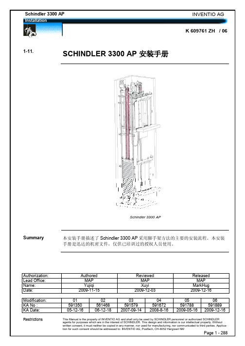
迅达电梯2012产品说明书
×√
大楼照明控制 (需用户配合)
√√
一站式残疾人服务
×√
两个消防返回楼层
√√
消防员控制 (只允许被授权人操作) √ √
消防员控制 (只允许被授权人操作) √ √
VIP运行 VIP运行 VIP运行 VIP运行 地震控制(接口) 背景音乐 轿厢到站钟 厅站到站钟 M10厅站到站钟 大楼监控接口 隐藏式键盘
kgmsmmmmmmmmmm63081008001400x11002000x1600425015501604300160017544001700800101008001400x13502000x180042501600160430016001754400170010002250x18501609002200x18504300160010002250x18501759002200x18504400170010002250x185010001310010001600x14002300x19004250160011001601000430016001100175100044001700110011501510011001950x14002750x200044001600160445016001754550170013501810011001950x15502750x210044001600160445016001754550170016002110011002000x17002850x22004400160016044501600175455017009001009001600x13502200x18502400x19002300x19002400x19002300x19002400x19004250160012载重人数速度轿厢门宽井道顶层高度底坑深度bkxtkbsxtsbthskhsg单入口轿厢1000131009001100x21002000x275042501600160430016001754400170011501510011001400x18002450x245044001600160445016001754550170013501810011001500x19502500x260044001600160445016001754550170016002110011001600x21002550x2750440016001604450160017545501700kgmsmmmmmmmmmm载重人数速度轿厢门井道顶层高度底坑深度bkxtkbsxtsbthskhsg双入口轿厢技术数据表schindler5400apmrl无机房控制功能代码功能名称代码功能名称asc1轿内数字指示器an2防捣乱功能召唤比较an1防捣乱功能最小负载ft强制关门超出运行时间控制fkzan3防捣乱功能门光幕kfm测试运行lv满载控制lx
迅达机电预留预埋施工方案
上海绿地建设(集团)有限公司迅达(中国)电梯有限公司-中国区总部、研发中心及制造中心项目四期工程机电工程预留预埋专项方案上海绿地建设(集团)有限公司二0一四年七月十日上海绿地建设(集团)有限公司目录第一章编制说明 (1)一、编制依据 (1)二、工程概况 (1)三、机电预埋、预留概况 (1)第二章施工准备 (2)一、技术准备 (2)二、人员准备 (2)三、物资准备 (3)四、多专业交叉配合 (3)第三章主要施工方法 (5)一、套管制作、安装 (5)二、给排水、空调水留洞 (8)三、空调风孔洞预留 (12)四、配电箱洞口预留、电缆桥架穿楼板和墙的洞口预留 (12)五、强弱电进户管线套管预留 (13)六、二次结构期间给排水支管安装 (13)七、电管预留预埋 (14)八、现浇混凝土楼板内电管敷设及要求 (16)九、接线盒埋设的控制要求 (17)十、二次结构内电气配管 (18)第四章技术质量保证措施 (20)一、质量目标 (20)二、保证质量采取的措施 (20)第五章安全及文明施工措施 (22)一、安全保护措施 (22)二、文明施工措施 (24)上海绿地建设(集团)有限公司第一章 编制说明一、编制依据1、迅达(中国)电梯有限公司-中国区总部、研发中心及制造中心项目四期工程机电设计图纸2、《建筑给水排水及采暖工程施工质量验收规范》(GB50242-2002)3、《建筑通风与空调工程施工质量验收规范》(GB50243-2002)4、《建筑电气工程施工质量验收规范》(GB50303-2011)5、各相关施工图集二、工程概况工程名称:迅达(中国)电梯有限公司中国区总部、研发中心及制造中心四期工程。
工程地址:上海市嘉定区,西至斜泾,南至兴顺路。
工程概况:本项目分为联合厂房+辅房1、2+办公生活楼+门卫房1、2共有六个单体。
其中联合厂房分为4个区:备件中心、电器装配车间、生产车间、堆货及装车发货区。
本项目为单层(局部多层)建筑,其中备件中心1层(局部2层);电器装配车间、生产车间、堆货及装车发货区为1层;辅房1、2为动力及设备用房地上2层;办公生活楼为3层;门卫1地下1层地上1层;门卫2地上1层。
- 1、下载文档前请自行甄别文档内容的完整性,平台不提供额外的编辑、内容补充、找答案等附加服务。
- 2、"仅部分预览"的文档,不可在线预览部分如存在完整性等问题,可反馈申请退款(可完整预览的文档不适用该条件!)。
- 3、如文档侵犯您的权益,请联系客服反馈,我们会尽快为您处理(人工客服工作时间:9:00-18:30)。
迅达A P M M R现场安装手册SANY标准化小组 #QS8QHH-HHGX8Q8-GNHHJ8-HHMHGN#安装缩略图摘要本手册提供了在亚太区范围内使用脚手架安装300P MMR主要安装步骤的详细说明。
本手册为保密文件,并仅供授权的培训人员使用。
目录1 安全建议 (4)概要 (4)使用符号 (4)2 先决条件 (5)产品概述 (5)安装步骤 (7)专用工具 (9)3 施工现场准备工作 (10)4 导轨安装 (15)准备工作 (15)导轨支架安装 (15)导轨安装 (21)导轨基座 (21)导轨安装 (22)连接板校正 (24)5 Varidor 30AP C2 厅门入口安装 (25)门框预安装 (27)地坎支架 (30)门框和机械横梁 (31)地坎和护脚板 (35)门板 (36)C2井道互锁装置 (40)门解锁装置 (41)安装门重锤 (42)防护罩 (44)6 PMS420无齿轮机组安装 (45)机组支架 (47)安装PMS420无齿轮机组 (48)*手动应急操作选配装置 (51)制动器调整和制动力测试 (57)*曳引钢丝绳悬挂装置安装 (58)*安装限速器 (62)7 *安装GGM2-AP对重 (71)先决条件 (71)*机械安装 (72)*缓冲器支撑 (72)*对重校正 (73)*安全钳(选配) (74)*导靴 (76)油杯(选配) (79)*对重块 (79)*补偿链悬挂装置 (80)地震传感器(选配) (81)*调整和最后检查 (82)对重防护屏 (83)*对重防护屏后置 (83)*对重防护屏侧置 (84)8 安装轿厢架FRS9-AP/FRM9-AP (87)安装轿厢架FRS9-AP (87)FRS9-AP安全钳和导靴选配件 (98)FRM9-AP安全钳和导靴选配件 (99)9 安装曳引绳 (100)处理钢丝绳 (100)安装钢丝绳 (101)钢丝绳绳头安装 (105)检查钢丝绳张紧度和绳的润滑 (109)限速器钢丝绳 (110)10 轿厢P9KD-AP(CM)安装 (117)轿厢安装步骤 (118)*安装轿厢装璜 (134)安装满载、超载开关 (143)轿厢平衡装置 (144)11 V30 AP轿门安装 (145)11.1 C2轿门 (145)11.1.1 轿门机驱动 (146)11.1.2 轿门板 (147)11.1.3 轿门刀 (149)安装光幕(MiniMax光幕LVH) (151)12 安装缓冲器 (157)13 安装补偿链 (159)补偿链导向装置 (159)4-滚轮导靴 (159)2-滚轮导靴 (162)补偿链 (165)14 安装MX-GC (170)先决条件 (170)材料范围 (171)控制柜 (172)井道信息 (174)井道信息IGSI (174)绝对值线型井道信息系统 (190)控制柜内模块 (210)机房电缆 (211)井道电缆 (215)准备 (220)安装 (223)调整和最后检查 (229)OKR (231)随行电缆 (236)带IGSI和LONCIB的MX-GC,HQ<=70m (237)带IGSI和LONCIB的MX-GC,HQ>70m (238)带IGSI和LONIC/LONICK的MX-GC,HQ<=70m (239)带IGSI和LONIC/LONICK的MX-GC,HQ>70m (240)控制柜内的概述与名称 (241)15 VARIODYN VF44BR和VF88BR安装 (243)VARIODYN VF44BR安装 (243)VARIODYN VF88BR安装 (249)1 安全建议概要安全要求所有参与的安装人员必须熟悉并遵守公司以及当地的安全规范,特别要注意以下几点:照明必须充足,以保证安全生产。
损坏或丢失的安全装备必须立即更换和及时补充。
所有的工具都必须处于良好的工作状态。
使用机械时,须遵照供应商提供的使用指南进行操作。
除了穿防护工作服以外,必须使用下列安全装备:号2 先决条件产品概述产品名称概览图Schindler 300P MMR概览部件清单安装步骤使用脚手架 的安装步骤 概述无脚手架的安装步骤概述专用工具特殊工具3 施工现场准备工作工地说明在安装开始前,进行工地例会与介绍来阐明必要的信息是非常重要的。
请参阅BDP004首要工地访问步骤。
工地介绍工地检查请注意到这步为止不要进行井道样板线设置,尽管下面的尺寸测定可能与土建图一致,但这些尺寸在设置样板线后仍然有可能有变化。
工地安装监督必须获悉所有非正常的结果。
工地检查1 干燥并且安全2 尺寸正确3 样板线设置并且确认位置4 工具使用的电源已经到位5 照明特别提醒注意工地上干净且干燥的条件是为用户提供准时安装一台高质量的电梯的绝对必要条件。
土建前期检查主要检查项目:井道检查:脚手架样板线安装样板线样板线检查货运AB2000057设备贮存确保贮存货物的地方干净,干燥,有下列几条预防措施保护的区域:·周边没有可燃材料存放。
·在储存区域里,没有工作遗留气体切断或进行任何其他可燃行为。
·若有进水的情况,货箱应能抬高转移到铁板上。
·排水沟应通畅。
·交通不拥挤的区域。
·有用于碎石掉下的保护。
·已用帆布或塑料薄膜包裹好。
·土建方应安排保安来防止货物的人为损坏或盗窃。
·若货箱有堆垛的需要,轻货箱应放在重货箱上面。
土建监督必须确保若因为别的工地需要部件,拿部件时不允许打开货箱然后不再关上被打开的货箱。
不管部件多小,都必须签收并为生产需要的部件的定购或投诉留一份复印件然后保存在工作文件中。
借件的借出和归还日期必须与本工地安装项目进度相适应。
“非工地”存放的设备应该与上面的条款一样进行处理。
特别注意必须按照下面的图例进行导轨的处理和存放。
导轨通常情况下为捆装提供并依靠叉车或起重机搬运。
导轨搬运与存放把电梯设备存放在外面开放式区域。
这样可以避免提供备件并让KG存在风险。
拉,并且移动重型部件时必须使用合适的机械设备。
型设备穿过混凝土路面时,必须得到土建方的认可,即如果混凝土路面还未加工处理须能够支撑部件的质量。
当有必要时,在混凝土地面下面支撑住来确保设备的通过。
原则,土建监督不应该在一个没有经验的工人在监督操作的情况下,让没有经验的工人吊操作。
用有合适维持拉力的设备来提升电梯部件。
可靠的吊索和绳索是必须的并且这些设备应建监督的常规检查。
4 导轨安装准备工作摘要在开始安装导轨前必须要安装导轨支架。
挑选并与支架一起安装。
在安装三重导轨支架时必须要小心。
检查导轨清洁导轨注意!用塑料或木制的锉刀把导轨表面的防腐蚀保护清除。
用合适的清洁剂清洁导轨。
用HLP68油涂到导轨表面来防止导轨的腐蚀。
导轨支架安装导轨固定调整布置图导轨安装布置图A 单入口,后置对重B 双入口,侧置对重 1 轿厢导轨支架 2 对重导轨支架3 轿厢-对重导轨支架(U 型支架)导轨固定调整AB2000057对重导轨支架概览图对重导轨支架概览图(T75)轿厢导轨支架概览图SF=105 (185)轿厢导轨支架概览图(T89)轿厢-对重导轨支架概览图轿厢-对重导轨支架概览图对重导轨支架1地脚螺栓 M16x105-125-St-A2K2对重导轨支架3大垫圈ISO7093-1-164RIP垫圈5M16螺母6水平仪轿厢导轨支架轿厢导轨支架固定1 地脚螺栓 M16x105-125-St-A2K2 轿厢导轨支架3 大垫圈ISO7093-1-164 RIP垫圈5 M16螺母6 水平仪7 样板线注意轿厢-对重导轨支架仅用于双侧门,侧置对重的电梯。
轿厢-对重导轨支架1 地脚螺栓 M16x105-125-St-A2K2 轿厢-对重导轨支架3 大垫圈ISO7093-1-164 RIP垫圈5 M16螺母6 水平仪7 样板线导轨安装4.3.1 导轨基座概览图导轨基座概览图摘要导轨底部基座会用在高楼(HQ>80m)来补偿土建收缩。
导轨基座和底坑组件不能同时使用。
导轨底部基座的装配图纸参见文件Z 210932。
布置图导轨基座布置图4.3.2 导轨安装摘要本节内容包括了在井道全长度内的导轨的定位和安装说明。
导轨靠表面的油膜保护并且在现场安装前应该存放在周围温度环境干燥的区域。
安装第一档导轨安装其他档导轨其他导轨的固定4030 调整导轨至正确位置。
4031通过四个螺栓、螺母和垫片固定导轨连接板,锁紧螺母。
其他导轨与连接板的固定4032重复这个安装方法安装下一档导轨。
安装最后一档导轨 4033 用4个螺栓、垫圈和螺母固定最后一档导轨到连接板,锁紧螺母。
导轨安装和调整 4034 固定导轨到导轨支架上。
4035 调整导轨的水平度和垂直度。
用校导尺在井道全长内检查导轨的位置。
4036 根据样板线到导轨A 的距离检查导轨的正确位置。
4037 根据轿厢导轨A 检查导轨B 的正确位置。
在井道全长内仔细检查导轨轨距BKS 的尺寸。
4038 检查导轨C 相对于轿厢导轨A 的正确位置。
4039 根据对重导轨C 检查导轨D 正确位置。
在井道全长内仔细检查对重导轨轨距BGS 的尺寸。
4040拧紧连接导轨支架的螺栓,紧固压导板。
为了获得好的运行质量,导轨接头必须使用“锉刀”在导轨接头处可见的不同部位进行校正修磨。
340_002523_01340_002529_01警告编号 步骤4041 在井道全长范围内检查导轨BKS 和BGS 的尺寸。
4042 检查螺栓连接的正确收缩性。
4043用特殊锉刀修平导轨连接处。
连接板调整警告5 Varidor 30AP C2厅门入口安装注意参照K604192安装Varidor 30AP T2厅门。
摘要 在安装Varidor 30AP 厅门之前,井道所有相关尺寸必须先进行测量。
2001420 000002 04 AP准备1样板线参数缩略图厅门C2缩略图1 护脚板2 护脚板固定装置3 厅门地坎支架4 厅门地坎侧面5 门板6 侧部固定7 厅门挂件8 厅门横梁9 厅门上坎支架门框预安装C2 盒装支架编号步骤5000把角铁固定件(1)插入到门立柱(3)顶部,并弯曲舌片NIBS(8)。
5001用4个M10×20的螺栓(4)和锁紧螺母(2)把框架头(5) 安装并固定在两边的厅门立柱上,并仅用手加紧。
5002在立柱(3)上闩合保护板(6),并弯曲两边的舌片NIBS(7)。
4 2 0 _ 0 0 0 0 8 5 _ 0 0 _ A P门框安装1 角铁固定件2 锁紧螺母3 立柱部件4 M10×20六角螺栓5 框架头6 保护板(C2)7 舌片NIBS8 舌片NIBS5003把侧柱(1)放到地坎托架(3)上并插入金属插片(2)固定,弯曲舌片(4)。
