数字信号处理英文版课后答案 (3)
数字信号处理 Chapter03答案

11
3.2 Properties of the z-Transform
Ex. ( linearity) x(n) = [3(2n) – 4(3n)] u(n) 3 4 – 1 – 2z –1 1 – 3z –1
X(z) =
ROC: |z| > 3
12
3.2 Properties of the z-Transform
z = re
jθ
=
n =−∞
∑ x ( n )r
−n
∞
− n − jθ n
e
X ( z) ≤
n =−∞
∞
∑
−1
x (n) r
+∑
n=0
∞
∞
x ( n) rn
x (n) rn
≤ ∑ x ( −n ) r + ∑
n n =1 n =0
7
3.1 The z-Transform
3.1.1 The Direct z-Transform
3.2 Properties of the z-Transform
X(z) = ∑ x(n) z – n
14
3.2 Properties of the z-Transform
X(z) = ∑ x(n) z – n
15
X(z) = ∑ x(n) z – n
16
3.3 Rational z-Transforms
1 2 −1 1 2 2
X ( z ) = 1+ z + (
X ( z) = 1 1− z
1 2 −1
)
z + .... + (
−2
1 n 2
)
z −n
数字信号处理英文版课后答案 (4)
4.24 From the figure, the filter has a finite impulse response. It may be described as a sum of impulse function as: h[n] = 0.5[n] + 0.4[n–1] + 0.3[n–2] + 0.2[n–2] The difference equation has the parallel form: y[n] = 0.5x[n] + 0.4x[n–1] + 0.3x[n–2] + 0.2x[n–3] 4.25 n h[n] The impulse response is finite, with samples as listed in the table. 0 1.000 1 0.300 2 0.090 3 0.027 4 0.000 5 0.000 6 0.000
x[n]
+
delay –0.14 delay –0.38
y[n]
4.23 n h[n]
The first ten samples of the impulse response are: 0 1.0 1 –1.2 2 –0.8 3 0.4 4 0.0 5 0.0 6 0.0 7 0.0 8 0.0 9 0.0
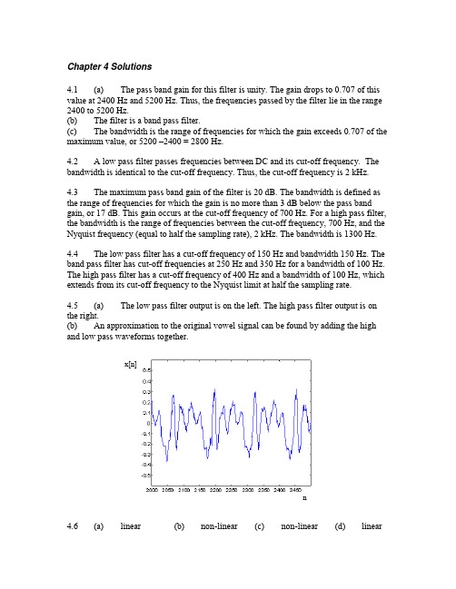
Chapter 4 Solutions 4.1 (a) The pass band gain for this filter is unity. The gain drops to 0.707 of this value at 2400 Hz and 5200 Hz. Thus, the frequencies passed by the filter lie in the range 2400 to 5200 Hz. (b) The filter is a band pass filter. (c) The bandwidth is the range of frequencies for which the gain exceeds 0.707 of the maximum value, or 5200 –2400 = 2800 Hz. 4.2 A low pass filter passes frequencies between DC and its cut-off frequency. The bandwidth is identical to the cut-off frequency. Thus, the cut-off frequency is 2 kHz. 4.3 The maximum pass band gain of the filter is 20 dB. The bandwidth is defined as the range of frequencies for which the gain is no more than 3 dB below the pass band gain, or 17 dB. This gain occurs at the cut-off frequency of 700 Hz. For a high pass filter, the bandwidth is the range of frequencies between the cut-off frequency, 700 Hz, and the Nyquist frequency (equal to half the sampling rate), 2 kHz. The bandwidth is 1300 Hz. 4.4 The low pass filter has a cut-off frequency of 150 Hz and bandwidth 150 Hz. The band pass filter has cut-off frequencies at 250 Hz and 350 Hz for a bandwidth of 100 Hz. The high pass filter has a cut-off frequency of 400 Hz and a bandwidth of 100 Hz, which extends from its cut-off frequency to the Nyquist limit at half the sampling rate. 4.5 (a) The low pass filter output is on the left. The high pass filter output is on the right. (b) An approximation to the original vowel signal can be found by adding the high and low pass waveforms together.
数字信号处理 英文版 课后习题
The difference equation can be found in two ways. By replacing h[n] with y[n] and [n] with x[n], the impulse response itself furnishes the difference equation y[n] = 2x[n] – 1.5x[n–1] + x[n–2] + 0.5x[n–3] Alternatively, the same difference equation can be found by using H(z) = Y(z)/X(z), cross-multiplying, and taking an inverse z transform. 6.9 n h[n] The samples of the impulse response are given in the table. 0 0.0 1 0.5625 2 0.3164 3 0.1780 4 0.0
The samples of the impulse responses are: 0 1.0 0.0 1 0.2 –3.0 2 0.04 –6.0 3 0.0 –9.0
The transfer functions of the systems are: H1(z) = 1 + 0.2z–1 + 0.04z–2 H2(z) = –3z–1 – 6z–2 – 9z–3 In cascade, the filters give the transfer function H(z) = H1(z)H2(z) = 3z 1 6.6z 2 10.32z 3 2.04z 4 0.36z 5 6.12 (b) 6.13 6.14
数字信号处理 英文版 课后习题
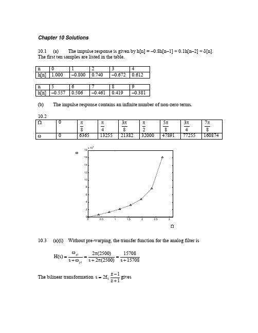
H(s)
p1 s p1
23946 s 23946
After the bilinear transformation, the digital transfer function is obtained:
H(z) 23946 0.6(1 z 1 ) z 1 1 0.1989z 1 16000 23946 z 1
: 2
The shape of the digital filter may be found by substituting 2f S tan
H ( )
1504.4 2 2f S tan 1504.4 2
2
1504.4 2 16000 tan 1504.4 2
(b)
Use the bilinear transformation to get the digital transfer function
1504.4 0.0859(1 z 1 ) H( z) z 1 1 0.8281z 1 16000 1504.4 z 1
The difference equation is y[n] = 0.8281y[n–1] + 0.0859x[n] + 0.0859x[n–1]. 0.0859(1 e j ) (d) The frequency response is H() . The magnitude response 1 0.8281e j may be found by taking the magnitudes of this expression for several values of . It is plotted below against frequency in Hz. (c)
数字信号处理(英文版)课后习题答案2
(Partial) Solutions to Assignment 2pp.73-761.16In each of the following systems, let or be the input and or be the output. Determine whether each systems is (1) linear, (2) time invariant, (3) causal, (4) BIBO stable(g).(i).ans: omitted----------------------------------------------------1.17 A linear time invariant system has impulse response Determine the output sequence for each of the followign input signals:(b)(f)(b) ans:h n is given byThe z-transform of []where ROC1:x n is given byz-transform of []where ROC2:h n is given byTherefore, the z-transform of the output []y nPerform inverse z to get [](f) ans: using the same method as in (b) (details omitted )----------------------------------------------------1.18. A linear time invariant system is defined by the difference equationb. Determine the output of the system when the intpu isc. Determine the output of the system when the input isans: omitted----------------------------------------------------1.19 The following expressions define linear time invariant systems. For each one determine the impulse respnose(a)(e)(a) ans: the impulse response is(e) ans: the impulse response is----------------------------------------------------1.20 Each of the following expressions defines a linear time invariant system. For each one determine whether it is BIBO stable or not(g)(k)BIBO: Bounded input and bounded output(g) ans: omitted(k) ans: omitted----------------------------------------------------1.21. Using the geometric series, for each of the following sequence determine the z-transform and its ROC(d)(g)(i)(d) ans:where ROC:(g) ans:The first part is equal towhere ROC1 isThe second part is equal towhere ROC2 isTherefore combining both parts:where ROC={ROC1 and ROC2}:(i) ans:where ROC: whole complex domain----------------------------------------------------1.22. You know what the and are. Using theproperties only (do not reuse the definition of the z-transform.) determine the z-transform of the following signals(c)(g)where ROC1:where ROC2:(c) ans: using z-transform property:We have:where ROC:(g) ans:details omitted. The final answer isTherefore combining both parts:where ROC={ROC1 and ROC2}:----------------------------------------------------1.23 Using partial fraction expansion, determine the inverse z-transform of the following functions:(c) ,(e) ,(c) ans:(e) ans:procedures are the same as above. details omitted.----------------------------------------------------1.24. For each of the followign linear difference equations, determine the impulse response, and indicate whether the system is BIBO stable or not(a)(c)(a) ans:Take z-transform on both sideswhere ROC:Because is finiteTherefore, the system is BIBO stable(c) ans: omitted (the same as (a))----------------------------------------------------1.25. Although most of the time we assume causality, a linear difference equation can be interpreted in a number of ways. Consider the linear difference equation(a) Determine the transfer function and the impulse response. Is the system causal ? BIBO stable ?(a) omitted.----------------------------------------------------1.26. 1.26 Consider the linear difference equation(a) Determine the transfer function . Do you have enough information to determine theregion of convergenceans:Don't have enough information to determine ROC.----------------------------------------------------1.27. Given the system described by the linear difference equationDetermine the output for each of the following input signals(a)(e)(a) ans:Take z-transform on both sides:----------------------------------------------------1.28. Repeat Problem 1.27 when the system is given in terms of the impulse responseBefore you do anything, is the system stable ? Does the frequency responseexist ?ans: omitted.----------------------------------------------------1.29. Repeat Problem 1.27 when the system isgiven by the linear difference equationBefore you do anything, is the system stable ? Does the frequency response exist ?Ans: omitted.----------------------------------------------------。
数字信号处理课后习题答案(全)1-7章
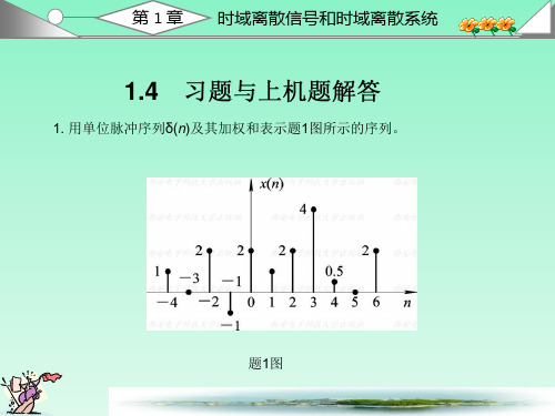
x(n)=-δ(n+2)+δ(n-1)+2δ(n-3)
h(n)=2δ(n)+δ(n-1)+ δ(n-2)
由于
x(n)*δ(n)=x(n)
1
x(n)*Aδ(n-k)=Ax(n-k)
2
故
第 1 章 时域离散信号和时域离散系统
y(n)=x(n)*h(n)
=x(n)*[2δ(n)+δ(n-1)+ δ(n-2) 1 2
(5) 系统是因果系统, 因为系统的输出不取决于x(n)的未来值。 如果
|x(n)|≤M, 则|y(n)|=|ex(n)|≤e|x(n)|≤eM,
7. 设线性时不变系统的单位脉冲响应h(n)和输入序列x(n)如题7图所示,
要求画出y(n)输出的波形。
解: 解法(一)采用列表法。
y(n)=x(n)*h(n)=
0≤m≤3
-4≤m≤n
非零区间如下:
第 1 章 时域离散信号和时域离散系统
根据非零区间, 将n分成四种情况求解: ① n<0时, y(n)=0
② 0≤n≤3时, y(n)= ③ 4≤n≤7时, y(n)= ④ n>7时, y(n)=0
1=n+1
n
1=8-m n0
3
mn4
第 1 章 时域离散信号和时域离散系统
第 1 章 时域离散信号和时域离散系统
(3) 这是一个延时器, 延时器是线性非时变系统, 下面证明。 令输入为
输出为
x(n-n1)
y′(n)=x(n-n1-n0) y(n-n1)=x(n-n1-n0)=y′(n) 故延时器是非时变系统。 由于
T[ax1(n)+bx2(n)]=ax1(n-n0)+bx2(n-n0) =aT[x1(n)]+bT[x2(n)]
数字信号处理(英文版)课后习题答案
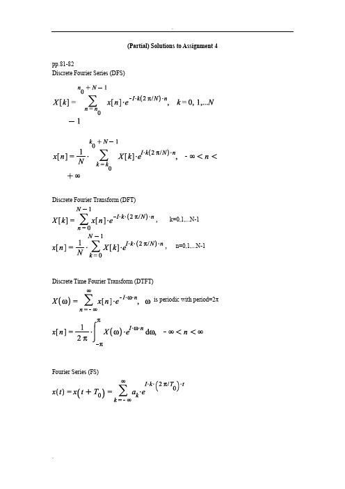
(Partial) Solutions to Assignment 4pp.81-82Discrete Fourier Series (DFS)Discrete Fourier Transform (DFT), k=0,1,...N-1, n=0,1,...N-1Discrete Time Fourier Transform (DTFT)is periodic with period=2πFourier Series (FS)Fourier Transform (FT)---------------------------------------------------- 2.1 Consider a sinusoidal signalQ2.1 Consider a sinusoidal signalthat is sampled at a frequency s F =2 kHza). Determine an expressoin for the sampled sequence , and determine itsdiscrete time Fourier transformb) Determinec) Re-compute ()X from ()X F and verify that you obtain the same expression as in (a)a). ans:=where andUsing the formular:b) ans:wherec). ans:Let be the sample function. The Fourier transform of isUsing the relationship orwhereConsider only the region where ( orthereforewhereEND-----------------------------2.3 For each shown, determine whereis the sampled sequence. The sampling frequence is given for each case.(b) Hz(d) Hztheory: the relationship between DTFT and FT iswhereorb. ans:d. ans:omitted (using the same method as above)----------------------------------------------------2.4 In the system shown, let the sequence be and the sampling frequency be kHz. Also let the lowpass filter be ideal, with bandwidth (a). Determine an expression for Also sketch the frequency spectrum (magnitude only) within the frequency range(b) Determine the output signal(a) ansFrom class notes, we have where is an ZOH interpolation function and We can writeFirstly, to findwhereIt can be found asSecondly, find This can be solved either by FT or DTFT.We can writewhere andUsing the formula:we haveUsing the formula,:we have from DTFT of y[n]Note the above expression is two pulses at and -the scaling factor is:whereTherefore,where(b) ans:After the ideal LPF, the Fourier transform ofTake inverse Fourier transform of , the output signal is:Note both the and θ terms are introduced by ZOH functionwhere is introduced because is non-ideal and θ represents the delay of----------------------------------------------------Q 2.5. We want to digitize and store a signal on a CD, and then reconstruct it at a later time. Let the signaland let the sampling frequency Hz.(a) Determine the continuous time signal after the reconstruction.(a) ans: Assuming (ZOH+ ideal LPF) is used. This problem can be solved by using the results directly from Q2.4. In Q2.5 there are 3 sinusoidal signals instead of only one in Q2.4. Details of the solutions are omitted.----------------------------------------------------Q 2.6 In the system shown, determine the output signal for each of the following input signal Assume the sampling frequency kHz and the low pass filter (LPF) to beideal, with bandwidth(b)(d)Ans (b) (d): same as in problem Q2.5.----------------------------------------------------2.7 Suppose in DAC you want to use a linear interpolation between samples, as shown in the accompanying figure. This reconstructor can be called a first order hold, because the equation of a line is a polynomial of degree 1(a). Show that with a triangular pulse as shownin the figure(b). Determine an expression for in terms ofand(c). In the accompanying figure, let kHz, and the filterbe ideal with bandwidth Determine the outputAns: omitted.----------------------------------------------------2.9 In the following system, let the signal be affected by some random error as shown. The error is white, zero mean, with variance Determine the variance of the error after the filter for each of the filter(b)(b) ans:The variance of the output of the filter is given byTherefore--------------------------------------------------------------------------------------------------------------------------------------------------------------------------------------------------------------------------------------------------------------------------------------------------------------------------------------------------------------------------------------------------------------------------------。
数字信号处理课后答案
⎣⎢y[3]⎦⎥ ⎣⎢1 − j −1 j ⎦⎥ ⎣⎢2 + j⎦⎥ ⎣⎢ 2 ⎦⎥
5.56 Similarly to the solution of Problem 5.55, we first calculate the DFT X[k] of x[n]: €
⎡X[0]⎤ ⎡1 1 1 1 ⎤ ⎡ 1 ⎤ ⎡ 2 ⎤
2
5.54 €
(a)
Given:
y[n] = αg[n] + βh[n]. Therefore:
Y[k]
=
N −1
∑
y[n]W
nk N
n=0
=
α
N −1
∑
g[n]WNnk
+
β
N −1
∑
h[n]WNnk
=
αG[k] +
βH[k].
€
n=0
n=0
€
(b) Given: x[n] = g[〈n − no〉N ]. Therefore:
∑ x[n]
y[〈
+
n〉
N
⎞ ⎟ W
k N
€
=0
=0⎝ n=0 €
⎠
=
N −1
∑
n=0
⎛N −1 x[n]⎜ ∑
⎝ =0
y[〈
+
n〉
N
]WNk
⎞ ⎟ ⎠
=
N −1
∑
n=0
⎛ x[n]⎜
⎝
N −1
∑
=0
y[m]W
(m−n) N
⎞ ⎟ ⎠
€
=
N −1
k
−
m2
〉
数字信号处理英文版课后答案(3)
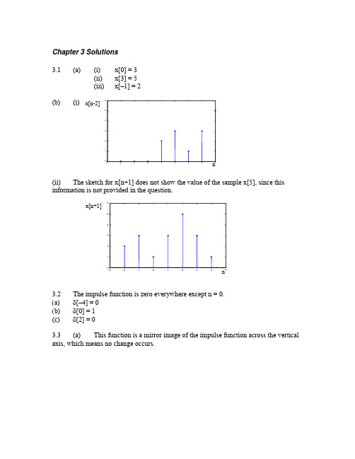
Chapter 3 Solutions3.1 (a) (i) x[0] = 3(ii) x[3] = 5(iii) x[–1] = 2(b) (i)(ii) The sketch for x[n+1] does not show the value of the sample x[5], since this information is not provided in the question.3.2 The impulse function is zero everywhere except n = 0.(a) δ[–4] = 0(b) δ[0] = 1(c) δ[2] = 03.3 (a) This function is a mirror image of the impulse function across the verticalaxis, which means no change occurs.(b) This function shifts the impulse two steps to the right and increases its amplitude to 2.(c) This function is the sum of two impulse functions.3.4 The step function is zero for n < 0 and one everywhere else.(a) u[–3] = 0(b) u[0] = 1(c) u[2] = 13.5 (a) x[n] = 4u[n–1](b) x[n] = –2u[n](c) x[n] = 2u[–n](d) x[n] = u[n–2](e) x[n] = u[2–n]3.6(a)(b)3.7 (a) This signal is a sum of shifted step functions, each with amplitude one. x[n] = 0.1u[n –1] + 0.1u[n –2] + 0.1u[n –3] + …(b) This signal is a sum of impulse functions with increasing amplitude. x[n] = 0.1δ[n –1] + 0.2δ[n –2] + 0.3δ[n –3] + …3.8 x[n] = (u[n] – u[n –2]) + (u[n –5] – u[n –7]) + (u[n –10] – u[n –12])3.9 x[n] = 2δ[n] – 3δ[n –1] + δ[n –2] – δ[n –3] + 3δ[n –4]3.10 (a)x[n] = δ[n –3] + δ[n –4] + δ[n –5] + δ[n –6] – δ[n –7] – δ[n –8] – δ[n –9] – δ[n –10] – δ[n –11] ∑∑==-δ--δ=117k 63k ]k n []k n [(b) x[n] = u[n –3] – 2u[n –7] + u[n –12] 3.11 x[n] = u[n] + 2u[n –4]3.123.13 The signal has values 1, 0.5, 0.25, 0.125, etc. These values can be generated from the function 0.5n , where each value is the amplitude of an impulse function. The signal may be expressed as ∑∞=-δ=0k k ]k n [)5.0(]n [x = δ[n] + 0.5δ[n –1] + 0.25δ[n –2] + 0.125δ[n –3] + …3.14 (a)By Euler’s identity, ⎪⎭⎫ ⎝⎛π-⎪⎭⎫ ⎝⎛π==π-4n sin j 4n cos e]n [x 4n j(b)From (a), 4π=Ω. Therefore, 18422=ππ=Ωπ. The digital period is 8 samples.3.15 (a)⎪⎭⎫⎝⎛π-⎪⎭⎫ ⎝⎛π==π-3n sin j 3n cos e ]n [x 3n j(b) The magnitude of any complex number is the square root of the sum of the squares of the real and imaginary parts. The magnitudes in the last column in (a) show that 3n j eπ- = 1. This equation is true for all n.3.16 The frequency of the analog signal is f = ω/2π = 200/2π Hz. The samplingfrequency f S = 1/T S = 1/(25x10–3) = 40 Hz. The digital frequency is Ω = 2πf/f S = 200/40 = 5 rads. The sampled signal is x[n] = 5sin(n Ω) = 5sin(5n).3.17 Check 2π/Ω for each function. The function is periodic if this ratio is rational. (a) 2π/Ω = 2π/(4/5) = 10π/4 = 5π/2This ratio is not rational, so the sinusoid is not periodic. (b) 2π/Ω = 2π/(6π/7) = 14/6 = 7/3This ratio is rational, and in lowest terms. The number in the numerator, 7, is the number of samples before the sequence repeats. (c) 2π/Ω = 2π/(2π/3) = 3This result may be seen as 3/1. Thus, the sinusoid is periodic with period 3.3.18 (a) From the equation for x(t), ω = 2πf = 1000π, so f = 500 Hz. Since seven samples are collected every three cycles, N = 7 and M = 3, so37M N 2==ΩπThis means SS f 5002f f 276π=π=π=Ω. Solving S f 500276π=π gives f S = 1167 Hz. (b) Since f S > 2f, the sampling rate is adequate to avoid aliasing.3.19 (a) The following samples are graphed below.(b) The ratio 2π/Ω is 2π/(4π/5)=10/4 = 5/2. The numerator, 5, indicates the sinusoidal sequence repeats every five samples. Because the denominator of the ratio is 2, these five samples are collected over two analog periods.(c) The analog signal is superimposed over the digital signal with a dashed line in the figure below.3.20 The analog frequency of x(t) is f = ω/(2π) = 2500π/(2π) = 1250 Hz. The digital frequency of x[n] is π/3 radians. These frequencies must be related through the equationSS f 12502f f 23π=π=π=ΩThe solution to this equation is f S = 7500 Hz. One other solution is possible, since⎪⎭⎫⎝⎛π=⎪⎭⎫ ⎝⎛π-π=⎪⎭⎫ ⎝⎛π3n 5cos 3n n 2cos 3n cos . This view givesSf 1250235π=π=Ωor f S = 1500 Hz. At this frequency, aliasing occurs. The signal appears at a frequency of 250 Hz. This explains why this second sampling rate works:315002502f f 2S π=π=π=Ω3.21 (a) From 052n 92=π+π, n = 59-. The shift moves the function left by 9/5samples. (b) The samples in the two signals do not match, because the shift is not an integer.(c) 951.052)0(92sin ]0[x 1=⎪⎭⎫ ⎝⎛π+π=927.052)1(92sin ]1[x 1=⎪⎭⎫ ⎝⎛π+π=(d) For a phase shift of two samples to the right,0)2(92n 92=θ+π=θ+π, so 94π-=θ. Thus, ⎪⎭⎫ ⎝⎛π-π=94n 92sin ]n [x 1. One period of this signal contains the same sample values as one period of x 2[n]. 3.22 (a)(b)(c)(d) 3.23(a)Since the digital sinusoid is periodic,M 10M N 2==Ωπ. Since Sf f 2π=Ω, M10f f S =. Therefore, 10Mf f S=. Possible frequencies f of the analog signal are defined by M = 1, 3, 7, 9, 11, …, that is, all integers that do not share any factors with 10. Other integers M result in a digital period less than 10. For 4 kHz sampling, the possible frequencies f are 400, 1200, 2800, 3600, 4400, … Hz. (b) The only two frequencies from (a) that lie within the Nyquist range are 400 Hz and 1200 Hz. All other frequencies f, when sampled at 4 kHz, produce aliases at 400 or 1200 Hz.3.24 A 16-bit image uses 16 bits to represent the gray scale level for each pixel in the image. A total of 65,536 gray scale values can be represented with 16 bits.3.25 Each square on the checkerboard is recorded by a 16 x 16 block of pixels. All pixels in the white squares have gray scale value 255. All pixels in the black squares have gray scale value 0.。
数字信号处理课后习题答案
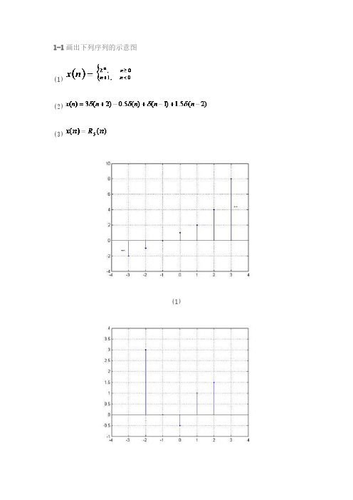
(修正:此题有错,
(3)系统的单位脉冲响应 而改变,是两个复序列信号之和)
(4)
(修正: 随上小题答案
(修正:此图错误,乘系数应该为 0.5,输出端 y(n)应该在两个延迟器 D 之间)
1-25 线性移不变离散时间系统的差分方程为
(1)求系统函数 ; (2)画出系统的一种模拟框图; (3)求使系统稳定的 A 的取值范围。 解:(1)
(2)
(3)
解:(1)
(2)
(3)
1-7 若采样信号 m(t)的采样频率 fs=1500Hz,下列信号经 m(t)采样后哪些信号不 失真? (1) (2) (3) 解:
(1)
采样不失真
(2)
采样不失真
(3)
,
采样失真
1-8 已知
,采样信号 的采样周期为 。
(1) 的截止模拟角频率 是多少?
(2)将 进行 A/D 采样后, 如何?
(3)最小阻带衰减 5-4
由分式(5.39)根据 A 计算 ,如下: 由表 5.1 根据过度带宽度 计算窗口:
单位脉冲响应如下:
单位脉冲响应如下:
其中 为凯泽窗。 5-5 答:减小窗口的长度 N,则滤波器的过度带增加,但最小阻带衰减保持不变。 5-6:图 5.30 中的滤波器包括了三类理想滤波器,包括了低通,带通和高通,其响应的单位
(1)
,
(2)
1-18 若当 时
;时
(1)
,其中
(2) 证明:
,收敛域
,其中 N 为整数。试证明: ,
(1) 令 其中
,则 ,
(2)
,
1-19 一系统的系统方程及初时条件分别如下: ,
(1)试求零输入响应 ,零状态响应 ,全响应 ; (2)画出系统的模拟框图 解: (1)零输入响应
数字信号处理—基于计算机的方法第3章答案
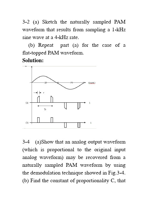
3-2 (a) Sketch the naturally sampled PAM waveform that results from sampling a 1-kHz sine wave at a 4-kHz rate.(b) Repeat part (a) for the case of a flat-topped PAM waveform.Solution:3-4 (a)Show that an analog output waveform (which is proportional to the original input analog waveform) may be recovered from a naturally sampled PAM waveform by using the demodulation technique showed in Fig.3-4.(b) Find the constant of proportionality C, thatis obtained with this demodulation technique , where w(t) is the oriqinal waveform and Cw(t) is the recovered waveform. Note that C is a function of n ,where the oscillator frequency isnfs.Solution:()()()()()()1111sin sin 2cos sin 2cos cos sin [cos 2cos cos sin 2cos s s jk ts k k k jk ts k k s s k s s s s s k n kt kT s t c ek d k d ded d k tk dk dk d w t w t d d k t k d v t w t n tk d w t d n t n d dd k t n tn k ddωωτππωπππωπωππωππωω∞∞-=-∞=-∞∞∞-=-∞=∞=∞=≠-⎡⎤=∏=⎢⎥⎣⎦==+⎡⎤=+⎢⎥⎣⎦==++∑∑∑∑∑∑2]s n t ω211cos cos 222s s n t n tωω=+after LPF:()()()sin sin o w t w t n d d n d n ddn dcw t c ππππ==∴=3-7 In a binary PCM system, if the quantizing noise is not to exceed P ± percent of the peak-to-peak analog level, show that the number of bits in each PCM word needs to be⎪⎭⎫⎝⎛=⎥⎦⎤⎢⎣⎡⎪⎪⎭⎫ ⎝⎛≥P pn 50log 32.350log 10] [log 10102(Hint: Look at Fig. 3-8c.)Solution:Binary PCM M=n2levelsforPPq V P n 100||≤We need)50(log)10(log 50log 5025011002 size step 1022pP n PM P M V P MV nPPPP ≥⎪⎭⎫⎝⎛≥≥=≤≤==δ)(log )(log )(log )(log )(log x b a x x b a b b a ==3-8 The information in an analog voltagewaveform is to be transmitted over a PCM system with a ±0.1% accuracy (full scale). The analog waveform has an absolute bandwidth of 100 Hz and an amplitude range of –10 to +10V .(a) Determine the minimum sampling rate needed.(b) Determine the number of bits needed in each PCM word.(c) Determine the minimum bit rate required in the PCM signal.(d) Determine the minimum absolute channel bandwidth required for transmission of this PCM signal. Solution:(a) Determine the minimum sampling rate needed./sec samples 200)100(22===B f s(b) Determine the number of bits needed in each PCM word.Using the results given in prob. 3-7.(c) Determine the minimum bit rate required in the PCM signal.s f w ords n bits K bits (9)200 1.8 w ord sec sec R ⎛⎫⎛⎫=== ⎪ ⎪⎝⎭⎝⎭(d) Determine the minimum absolute channelbandwidth required for transmission of this920.1%0.1%24250025125009V V V M and n bits a PC M w ord δδδ±=±→====>=→PCM signal.For binary PCM D=RHz9002==⇒D B3-9 An 850-Mbyte hard disk is used to store PCM data. Suppose that a voice-frequency (VF) signal is sampled at 8 ksamples/s and the encoded PCM is to have an average SNR of at least 30dB. How many minutes of VF conversation (i.e., PCM data) can be stored on the hard disk? Solution:53002.6230lg 1022=→=∴=≥=⎪⎭⎫⎝⎛n n M dB MM N S nsec 58sec 40sec 405sec 8kbytes bits byte kbits R kbits sample bits ksamples n f R s =⎪⎭⎫ ⎝⎛⎪⎭⎫ ⎝⎛=⇒=⎪⎪⎭⎫⎝⎛⎪⎭⎫ ⎝⎛==min13,47min 833,2minsec/60sec 10170sec 10170sec10170sec 10510850sec585033336hrs T kbytes Mbytes T ==⨯=⨯=⇒⨯=⨯⨯==3-10 An analog signal with a bandwidth of 4.2 MHz is to be converted into binary PCM and transmitted over a channel, The peak-signal quantizing noise ratio at the receiver output must be at least 55 dB.(a) If we assume that 0=Pe and that there is no ISI, what will be the word length and the number of quantizing steps needed?(b) What will be the equivalent bit rate? (c) What will be the channel null bandwidth required if rectangular pulse shapes are used? Solution:(a) If we assume that 0eP = and that there is no ISI, what will be the word length and the num-ber of quantizing steps needed? Using(3-18),lengthword 9 34.85577.402.6bitsn use n n dB N S peak =⇒≥⇒≥+=⎪⎭⎫⎝⎛steps quantizing 512229===nM(b)sec Mbits6.75Sample bits 9sec 4.8ecMsamples/s4.8)MHz 2.4(22log=⎪⎪⎭⎫ ⎝⎛⎪⎭⎫⎝⎛=====Msamplesn f R f f s anasFor rectangular pulse shapeMHz 6.75==R B null3-12 G iven an audio signal with spectralcomponents in the frequency band 300 to 3000Hz, assume that a sampling rate of 7KHz will be used to generate a PCM signal .Design an appropriate PCM system as follows:a. Draw a block diagram of the PCM system , including the transmitter, channel, receiver.b. S pecify the number of uniform quantization steps needed and the channel null bandwidth required , assume that the peak signal-to-noise ratio at the receiver output needs to be at least 30dB and that polar NRZ signaling is used.c. Discuss how nonuniform quantization canbe used to improve the performance of the system.Solution: (a) 略 (b)lengthword 5 10.43077.402.6bitsn use n n dB N S peak=⇒≥⇒≥+=⎪⎭⎫ ⎝⎛stepsquantizing 32225===nM7sam ples/sec 7 5bits K bits 35 sec Sam ple sec s s f K K sam plesR f n =⎛⎫⎛⎫===⎪⎪⎝⎭⎝⎭()KHzR B null 35==∴( c) uniform quantizing : for all samples,the quantizing noise power is the same 122δ=N↑→↓→NS signal big N S signal smalluniform quantizing is not good for small signal.Nonuniform quantizing: samples are nonlinear processed,Small signal is amplified↑→N S(or small signal ---using small step size ↑→N S )3-14 In a PCM system , the bits error rate dueto channel noise is 10-4. Assume that peak signal-to-noise ratio on the received analog signal needed to be at least 30dB.(a) Find the minimum number of quantizing steps that can be used to encode the analog signal into a PCM signal.(b) If the original analog signal had an absolute bandwidth of 2.7kHz , what is the null bandwidth of PCM signal for the polar NRZ signaling case.Solution: (a) 410-=PedB N S PKout30≥⎪⎭⎫⎝⎛()2231000141PK out S M N M Pe⎛⎫=≥ ⎪+-⎝⎭52206.19===≥n M M use M nKz f s 4.57.22=⨯=27KHz R /274.55===⨯==nullsB sKb nf R 3-17 For a 4 bit PCM system , calculate and sketch a plot of the output SNR(in decibels) as a function of the relative input level , ()20lg rmsx V for(a) A PCM system that uses 10μ= law companding(b) A PCM system that uses uniform quantizationWhich of these system is better to use in practice? Why?Solution: n = 4 bits ---- a PCM word (a)()()()6.02 4.7720lg ln 16.024 4.7720lg ln 11021.25dB SNn dBμ=+-+⎡⎤⎣⎦=⨯+-+⎡⎤⎣⎦=(b)() 6.02 4.7720lg ()6.024 4.7720lg ()28.8520lg ()rm s dBrm s rm s S N n x V x V x V =++=⨯++=+3-19 A multilevel digital communication system sends one of 16 possible levels over the channel every 0.8 ms .(a) What is the number of bits corresponding to each level? (b) What is the baud rate? (c) What is the bit rate? Solution:(a) What is the number of bits corresponding to each level?2164/lL l bits level==⇒=(b) What is the baud rate?311,2500.810secN sym bol D baudT -===⨯(c) What is the bit rate?kbits/sec5)250,1(4===lD R3-20 A multilevel digital communication system is to operate at a data rate of 9,600 bits/s.(a) If 4-bit words are encoded into each level for transmission over the channel, what is the minimum required bandwidth for the channel?(b) Repeat part (a) for the case of 8-bit encoding into each level. Solution:(a) If 4-bit words are encoded into each level for transmission over the channel. What is the min-imum required bandwidth for the channel?(b) Repeat part (a) for the case of 8-bit encoding into each level.600600)1200(2121baud 120089600minHz B HzD B D ===≥==3-24 Consider a random data pattern consisting of binary 1’s and 0’s, where the probability of obtaining either a binary 1 or abinary 0 is21. Calculate the PSD for thefollowing types of signaling formats as a function of b T ,the time needed to send 1 bit of data:(a) Polar RZ signaling where the pulse width isbT 21=τ.(b) Manchester RZ signaling where the pulse width isbT 41=τ. What is the first nullbandwidth of these signals? What is the spectral efficiency for each of these signaling cases? Solution:(a) Polar RZ signaling where the pulse width is bT 21=τ.sin(/2)()[()]2/2b b b T fT F f F f t fT ππ==and the data are independent from bit to bit1:1:210,2n n b a AV AV →+→-,依概率依概率()222:01,221,2nn knFor k A a a a and I A +=⎧⎪⎪===⎨⎪-⎪⎩依概率依概率()2222111(0)()22n n i ii R a a P A A A ===⨯+-⨯=∑The first-null bandwidth is RT B bnull 22==andthe bandwidth efficiency is12R B η==(b) Manchester RZ signaling where the pulse width isbT 41=τ. What is the first nullband-width of these signals? What is the spectral efficiency for each of these signaling cases?()()2,0:3400,0A k Thus R k k ⎧==-⎨≠⎩()()22S s2222222()P ()336T sin (/2)12(/2)sin (/2)4(/2)sj k f T k b b b b b b b F f fR k a T fT A T fT A T fT fT eπππππ∞=-∞=-⎛⎫= ⎪⎝⎭=∑Equation (3-36) can also be used to evaluate the PSD for RZ Manchester signaling where the pulse shape is shown in the figure.⎥⎦⎤⎢⎣⎡-⎪⎪⎭⎫ ⎝⎛=-22)sin()(τωτωτπτπτj j ee f f f F⎪⎭⎫⎝⎛⎪⎪⎭⎫ ⎝⎛=⇒2sin )sin(2)(ωττπτπτf f j f FUsing (3-40) and (3-36), the PSD forManchester signaling is()()2222)][sin(sin 4)(τπτπτπτf f f T A f p b⎥⎦⎤⎢⎣⎡=IfbT 41=τ, this becomes2224sin 44sin 41)(⎥⎦⎤⎢⎣⎡⎪⎭⎫ ⎝⎛⎥⎥⎥⎥⎦⎤⎢⎢⎢⎢⎣⎡⎪⎭⎫⎝⎛⎪⎭⎫ ⎝⎛=b b b b fT fT fT T A f p πππThe first-null bandwidth is RT B bnull 44==and thespectral efficiency is41=η(bits/sec)/Hz.3-29 The data stream 01101000101 appears at the input of a differential encoder. Depending on the initial start-up condition of the encoder, find out two possible differential encoded data streams that can appear at the output. Solution:3-30 Create a practical block diagram for a differential encoding system. Explain how thesystem work by showing the encoding and decoding for the sequence 001111010001. Assume that the reference digit is a binary 1. Show that error propagation can not occur. Solution:3-34 The information in an analog waveform is first encoded into binary PCM and then converted to a multilevel signal for transmission over the channel. The number of multilevels is eight. Assume that the analog signa has a bandwidth of 2700Hz and is tobe reproduced at the receiver output with an accuracy of 1%±(full scall).(a) Determine the minimum bit rate of the PCM signal.(b) Determine the minimum baud rate of the multilevel signal.(c) Determine the minimum absolute channel bandwidth required for transmission of this PCM signal. Solution:1221%50624100V M n V V δδδ±=±→=→==→= m in ()62270032.4/()28332.410.83()5.42s la R nf kb s b L L l R D kBdlD c B kH z==⨯⨯=========3-35 A binary waveform of 9600bits/s is converted into an octal (Multilevel) waveform that is pass through a channel with a raisedcosine-rolloff Nyquist filter characteristic . The channel has a conditioned (equalized) phase response out to 2.4kHz .(a) What is the baud rate of the multilevel signal?(b) What is the rolloff factor of the filtercharacteristic?Solution:09600()8332003()(1)(1) 2.40.52R a L l D Bdl D b B f r r kH z r =→=====+=+=→=3-37 A binary communication system uses polar signal. The overall impulse response is designed to be of thesin x xtype, as given byEq(3-67),so that there will be no ISI. The bitrate is 300/s R f bit s ==.(a) What is the baud rate of the polar signal? (b) Plot the waveform of polar signal at the system output when the input binary data is 01100101. Can you discern the data by looking at this polar waveform? Solution:1502s T f B H z==(b)sin ()s e s f t h t f t ππ=1()eSsf H f f f ⎛⎫= ⎪⎝⎭∏1Ss f DT ==3-43 Using the results of prob.3-42, demonstrate that the following filter characteristics do or do not satisfy Nyquist ’s criterion for eliminating ISI (0022s f f T ==).()()00122eT a H f fT ⎛⎫=⎪⎝⎭∏()()00223eT b H f fT ⎛⎫=⎪⎝⎭∏Solution:()()000012222e T T f a H ffT f ⎛⎫⎛⎫==⎪ ⎪⎝⎭⎝⎭∏∏()()0000232322eT T f b H f fT f ⎛⎫⎪⎛⎫==⎪⎪⎝⎭⎪⎝⎭∏∏3-45 An analog signal is to be converted into a PCM signal that is a binary polar NRZ line code. The signal is transmitted over a channel that is absolutely bandlimited to 4kHz. Assume that the PCM quantizer has 16 steps and that the overall equivalent system transfer function is of the raised cosine-rolloff type with r =0.5.(a) Find the maximum PCM bit rate that can be supported by this system without introducing ISI.(b) Find the maximum bandwidth that canbe permitted for the analog signal . Solution:()0:164 a PC M w ord 40.522 5.33/1T T M n B kH zr B a R D f kb sr==→=====⨯=+量化器()analog analog 2 5.331000667224s b R nf n B R B H zn=≥⋅⨯∴≤==⨯3-47 Multilevel data with an equivalent bit rate of 2,400 bits/s is sent over a channel using a four-level line code that has a rectangular pulse shape at the output of the transmitter. The overall transmission system (i.e., the transmitter, channel, and receiver) has an r =0.5 raised cosine-rolloff Nyquist filtercharacteristic.(a) Find the baud rate of the received signal.(b) Find the 6-dB bandwidth for this transmission system.(c) Find the absolute bandwidth for the system. Solution:(a) Find the baud rate of the received signal.242=⇒==l L l2400/1200aud2D R l B ===(b) Find the 6-dB bandwidth for thistransmission system.611(1200)600H z 22dB B D ===(c) Find the absolute bandwidth for the system.113(1)(10.5)(1200)(1200)900224absolute T B B r D H z==+=+==3-54 One analog waveform w 1(t ) is bandlimited to 3 kHz, and another, w 2(t), is bandlimited to 9 kHz. These two signals are to be sent by TDM over a PAM-type system. (a) Determine the minimum sampling frequency for each signal, and design a TDM commutator and decommutator to accommodate the signals.(b) Draw some typical waveforms for w 1(t ) and w 2(t ), and sketch the corresponding TDM PAM waveform. Solution:(a) Determine the minimum sampling frequency for each signal, and design a TDM commutator and decommutator to accommodate the signals. TDM1122(): 3kH z 6ksam ples/sec (): 9kH z 18ksam ples/secs s t B f t B f ωω=⇒==⇒=(b) Draw some typical waveforms for w 1(t ) and w 2(t ), and sketch the corresponding TDM PAM waveform.3-56 Twenty-three analog signals , each with a bandwidth of 3.4kHz, are sampled at an 8-kHz rate and multiplexed together with a synchronization channel (8kHz)into a TDM PAM signal. This TDM signal is passed through a channel with an overall raised cosine-rolloff Nyquist filter characteristic of r=0.75.(a) Draw a block diagram for the system, indicating the fc of the commutator and the overall pulse rate of the TDM PAM signal.(b) Evaluate the absolute bandwidth required for the channel.Solution:248k pulses/sec=192k pulses/sec D =⨯()()192k pulse/sec110.75168kH z 22D B r =+=+=3-58 Rework Prob.3-56 for a TDM pulse code modulation system in witch an 8-bit quantizer is used to generate the PCM words for each of the analog inputs and an 8-bit synchronization word is used in the synchronization channel.Solution:3-59 Design a TDM PCM system that will accommodate four 300-bit/s (synchronous) digital inputs and one analog input that has a bandwidth of 500Hz. Assume that the analog samples will be encoded into 4-bit PCM word. Draw a block diagram for your design, analogous to Fig.3-39, indicating the data rates at the various points on the diagram. Explain how your design works.Solution:3-60 Design a TDM PCM system that will accommodate two 2400-bit/s synchronous digital inputs and an analog input that has a bandwidth of 2700 Hz. Assume that the analog input is sampled at 1.11111 times the Nyquist rate and converted into 4-bit PCM word. Draw a block diagram for your design, and indicate the data rates at the various points on your diagram. Explain how your TDM scheme works.Solution:。
数字信号处理 Mitra 第三版 答案
4.
Page 290, Problem 5.12:
Replace
“
x1[n]
=
⎜⎝⎛
x[n]
+
x[
N 2
+ n]⎟⎠⎞WNn ” with
“
x1[n]
=
⎜⎝⎛ x[n] −
x[ N
2
+
n] ⎟⎠⎞ WNn
”.
5.
Page 291, Problem 5.15: Replace “ h[n] = ⎩⎨⎧x[0n,],
3. Page 418, Problem 7.53: Replace “ − j0.3 ” with “ − j ”.
4. Page 421, Problem 7.79: Replace “ 0.5 − 0.4z −1 + 0.8z −2 + 0.8z −3 − 0.4z −4 + 0.5z −5 ” with “ − 0.1 + 0.5z −1 + 0.05z −2 + 0.05z −3 + 0.5z −4 − 0.1z −5 ”.
4.
Page 161, Problem 3.6(d):
Replace
“
X
a
⎜⎛ ⎝
Ω a
⎟⎞ ⎠
”
with
“
X
a
⎜⎛ ⎝
j
Ω a
⎟⎞ ⎠
”.
5. Page 162, Problem 3.16: Replace “1.. ” with “1. ”.
1
6.
Page 163, Problem 3.21(d):
12. Page 167, Problem 3.61(d): Replace “ Hb (e jω ) ” with “ Hd (e jω ) ”.
数字信号处理课后答案第三章3

1e 4
1
(1)k
j k
1e 4
当 k 2,4,6,... 时,X%1(k) 0
序列2: X%2 (k)
2 j nk
e4
n0
j 3 k
1
e
4 j
k
1e 4
当 k 2,4,6,... 时,X%1(k) 0
序列3:
x%3(n) x%1(n) x%1(n 4)
故 f (n)中只有 n 5到 n 14的点对应于 x(n) y(n)
应该得到的点。
10. 已知两个有限长序列为
n 1, 0 n 3
x(n)
0,
4n6
y(n)
1,
1,
0n4 5n6
试用作图表示 x(n) ,y(n)以及 f (n) x(n) ⑦ y(n) 。
又因N必须为2的整数幂,所以一个记录中的
最少点数为 N 210 1024
x((n))5
x((n))6 x((n))6 R6 (n)
x((n 3))5 R5(n)
x((n))3 R3(n) x((n))7 R7 (n)
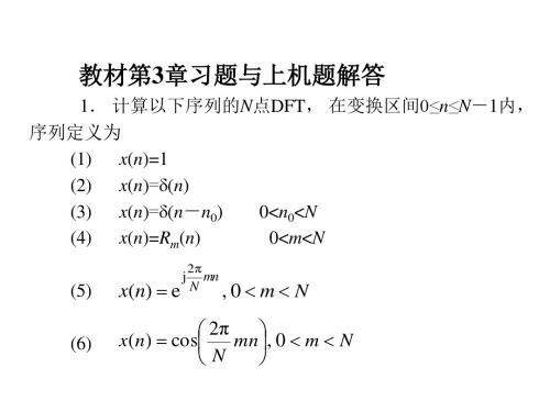
5. 试求以下有限长序列的N 点DFT(闭合形式表
达式):
(2) x(n) anRN (n)
N 1
解:X (k) x(n)WNnk RN (k)
根据序列移位性质可知
X%3 (k )
X%1 (k )
e
j k X%1 (k )
(1
ej kΒιβλιοθήκη )1(1)k j k
1e 4
数字信号处理英文版课后答案 (2)
0
10
20
30
40
50
60
70
80
90 100 110 120 130 140 150
Frequency, kHz
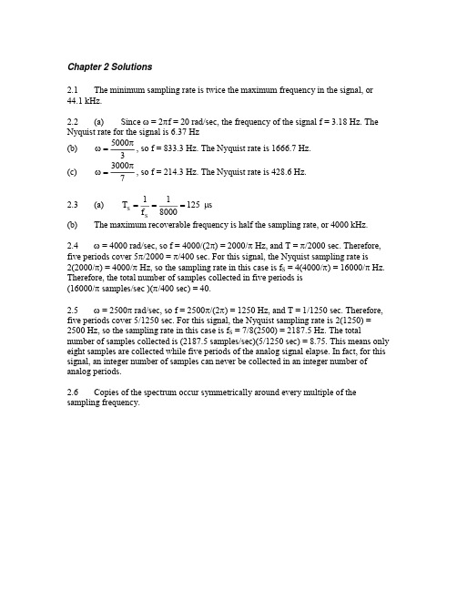
(b) The sampling rate is too low for this signal, so aliasing occurs. Spectral images are shown by dashed lines, while the final spectrum is shown as a solid line.
0
10
20
30
ห้องสมุดไป่ตู้
40
50
60
70
80
90 100 110 120 130 140 150
Frequency, kHz
2.8 The cell phone signal is band-limited. The transmission range is 30 kHz wide. The minimum sampling rate must be at least 60 kHz. In this case, a 60 kHz sampling rate is adequate. A baseband copy of the transmission can be recovered by a filter with a 30 kHz cut-off.
2.13 Since images of the target appear at 0 0.2 MHz, 2 0.2 MHz, 4 0.2 MHz, … 900 0.2 MHz, the actual frequency of the target is 900.2 MHz. 2.14 In each revolution of the wheel, the tire covers d = .635 = 1.995 m. The bicycle travels 15 km/h, or 15000/3600 = 4.17 m/sec. Thus, each tire of the bicycle revolves at 4.17 m/sec the rate of 2.09 cycles/sec . According to Nyquist, at least two samples 1.995 m/cycle must be taken per cycle, for a sampling rate of 4.18 samples/sec. This can be accomplished by taking 418 snapshots in every 100 seconds. 2.15 When the signal is sampled at 600 Hz, images of the sine wave’s frequency on either side of every multiple of the sampling frequency. Since the aliased frequency is 150 Hz, copies appear at 0 ±150, 600 ±150, 1200 ±150, etc. Only 150, 450 and 750 Hz lie below 1 kHz. When the sampling rate is 550 Hz, the aliased frequency is 200 Hz, so copies must appear at 0 ± 50, 550 ±200, 1100 ±200, etc. Only 200, 350, 750 and 900 Hz lie below 1 kHz. The only sine wave that is consistent with both sampling results has a frequency of 750 Hz. 2.16 (a) (b) (c) 2.17 The range of analog voltages is 6 V. quantization step = 6/24 = 375 mV quantization step = 6/28 = 23.44 mV quantization step = 6/216 = 91.55 V (a) 28 = 256 (b) 210 = 1024 (c) 212 = 4096
数字信号处理第三章习题答案
解 (1) 已知F=50Hz (2) (3)
(4)频带宽度不变就意味着采样间隔T不变, 应该使记录时间 扩大一倍为0.04s实现频率分辨率提高1倍(F变为原来的1/2).
解
、
和
(a)、(b)、(c)所示。
分别如题3解图
x1(n) (a)
x2(n) (b)
y (n)
(a)
(b)
(c) (c)
5.如果X(k)=DFT[ x(n)], 证明DFT的初值定 理 证明 由IDFT定义式
可知
14.两个有限长序列x(n)和y(n)的零值区间为 x(n)=0, n<0, 8≤n y(n)=0, n<0, 20 ≤ n
对每个序列作20点DFT, 即
X (k)=DFT [x(n)],
Y(k)=DFT [y(n)],
如果
F(k)=X(k)▪Y(k),
k=0,1,…,19 k=0,1,…,19 k=0,1,…,19
f(n)=IDFT [F(k)], k=0,1,…,19
试问在哪些点上f(n)=x(n)*y(n)?为什么?
解 如前所述, 记
,而
fl(n)长度为27,f(n)长度为20.前面已推出二者的关系为
只有在如上周期延拓序列中无混叠的点上, 才满足f(n)=fl(n)7
21-47
41-67
1-7
21-27
8-20
7-19 当从0开始时候
15.用微处理器对实数序列作谱分析, 要求谱分辨率F≤50Hz, 信号最高频率为1kHz, 试确定以下各参数;
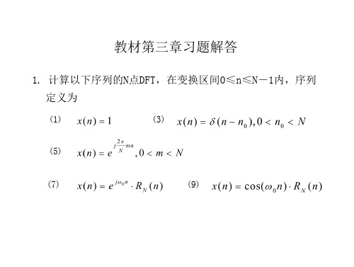
教材第三章习题解答
数字信号处理作业3(附答案)

6
7
8
a. b. c. 1 2 3 1 1 3 3 3 | | | 2 3 2 3 2 1 1 1 | 9 1 1 3 1 3 | | 26/25 7 18 7 18 6 24 6 24 ROC: -3<Re(s)<1
With the ROC in b., we have 1 2 3
-1
-0.5
0 t
0.5
1
1.5
2
5
1 1 2 2 5 6 1 1 2 2 3
For each non-empty ROC, X(s) corresponds to a x(t). X(s) has 3 poles: -1, -2 and -3. There are 8 possible ROCs (shown in the following table). And 4 of them are not empty, so there are 4 distinct signals with the expression X(s). -3 C C C C AC AC AC AC -2 C C AC AC C C AC AC -1 ROC C Re(s)>-1 AC -2<Re(s)<-1 C empty AC -3<Re(s)<-2 C empty AC empty C empty AC Re(s)<-3
ECE-S 631 Homework 3 solution 1 The following solutions are based on the assumption that the signals are causal.
பைடு நூலகம்
2 The following solutions are given based on the assumption that the signals are causal.
数字信号处理课后答案 第3章DFT FFT.
X 9 (k ) x9 (n)W
n 0
N 1
kn N
1 [e j0n e j0n ]e 2 n 0
N 1
j
2π kn N
1 1 e j0 N 1 e j0 N 2π 2π j(0 k ) j(0 k ) 2 N N 1 e 1 e
N 1
N 1
2π
2π
2π
1 e 2 n 0
N 1
j
2π ( mk ) n N
1 e 2 n 0
N 1 j 2 π ( m k ) n N
2π 2π j (mk ) N j ( m k ) N 1 1 e N 1 e N 2π 2π 2 j (m k ) 1 e j N ( mk ) N 1 e
kn X (k ) x(n)WN n 0 N 1
所以
DFT[ X (n)] X (n)W
n 0
N 1
N 1
kn N
N 1 mn kn x(m)WN WN n 0 m 0
N 1
n ( m k ) x(m)WN m 0 n 0
1knnknnnnknnnnknnwkx2j2j102j10e1e1e1????????????12100nkkn?2110001xk1nw1nnknnnnnkn????30010010001nw1nknnnnknnknnnxknnwwnkn??????n1j10n???sin1ekn1sinkmnknmmkknnnnmkwxkwrwk??????????????452j2j102j102je1e1eekmnnkmnnnnkmnknnnnmnnwkx?????????????mkmkn00kn16knnnnnnmnnmnnknnwmnnkx2j10102j2jeee212cos?????????22n11jj0011ee22nnmkn?mknnnn?????????????????????2j2j2j2je1e1e1e121kmnnkmnkmnnkmn20nkmknmkmknm???????0kn1700002nj2n11jj72nj001eee1eknnnknnknnknnxkw???????021n0j202nsin2e01k12nsin2nknknk??????????????????或110e1e12jj700????nkkxknn?8解法一直接计算
- 1、下载文档前请自行甄别文档内容的完整性,平台不提供额外的编辑、内容补充、找答案等附加服务。
- 2、"仅部分预览"的文档,不可在线预览部分如存在完整性等问题,可反馈申请退款(可完整预览的文档不适用该条件!)。
- 3、如文档侵犯您的权益,请联系客服反馈,我们会尽快为您处理(人工客服工作时间:9:00-18:30)。
x[n]
1 0.8
0.6
0.4
0.2
0 -3 -2 -1 0 1 2
n
3
(b) to 2.
This function shifts the impulse two steps to the right and increases its amplitude
x[n]
1.5
2
1
0.5
0 -3 -2 -1 0 1 2 3
4
5
n
(b)
x[n]
1 0.8
0.6
0.4
0.2
0 -3 -2 -1 0 1 2 3 4
n
5
3.7 (a) This signal is a sum of shifted step functions, each with amplitude one. x[n] = 0.1u[n–1] + 0.1u[n–2] + 0.1u[n–3] + …
(a) 0 0.00 6 1.18
The following samples are graphed below. 1 1.18 2 3 –1.90 1.90 4 5 –1.18 0.00 11 1.18 12 –1.90
7 8 –1.90 1.90
9 10 –1.18 0.00
(b) The ratio 2/ is 2/(4/5)=10/4 = 5/2. The numerator, 5, indicates the sinusoidal sequence repeats every five samples. Because the denominator of the ratio is 2, these five samples are collected over two analog periods.
n
(c)
This function is the sum of two impulse functions.
x[n]
5
4
3
2
1
0
-1
-2
-3 -3 -2 -1 0 1 2 3
n
3.4 (a) (b) (c) 3.5
The step function is zero for n < 0 and one everywhere else. u[–3] = 0 u[0] = 1 u[2] = 1 (a) x[n] = 4u[n–1]
(b) The magnitude of any complex number is the square root of the sum of the squares of the real and imaginary parts. The magnitudes in the last column in (a) show that e
-2
-1
0
1
2
3
4
5
n
(d)
x[n] = u[n–2]
x[n]
1
0.8
0.6
0.4
0.2
0 -3
-2
-1
0
1
2
3
4
5
n
(e)
x[n] = u[2–n]
x[n]
0.8
1
0.6
0.4
0.2
0 -3 -2 -1 0 1 2 3 4 5
n
3.6 (a)
x[n]
2.5
2
1.5
1
0.5
0 -3
-2
-1
0
1
2
3
j n 3
= 1. This equation is true for all n.
3.16 The frequency of the analog signal is f = /2= 200/2 Hz. The sampling frequency fS = 1/TS = 1/(25x10–3) = 40 Hz. The digital frequency is = 2f/fS = 200/40 = 5 rads. The sampled signal is x[n] = 5sin(n) = 5sin(5n). 3.17 Check 2/ for each function. The function is periodic if this ratio is rational. (a) 2/ = 2/(4/5) = 10/4 = 5/2 This ratio is not rational, so the sinusoid is not periodic. (b) 2/ = 2/(6/7) = 14/6 = 7/3 This ratio is rational, and in lowest terms. The number in the numerator, 7, is the number of samples before the sequence repeats. (c) 2/ = 2/(2/3) = 3 This result may be seen as 3/1. Thus, the sinusoid is periodic with period 3. 3.18 (a) From the equation for x(t), = 2f = 1000, so f = 500 Hz. Since seven samples are collected every three cycles, N = 7 and M = 3, so
n n cos j sin 3 3
n 0 1 2 3 4 5
1.0000 0.5000 – j0.8660 –0.5000 – j0.8660 –1.0000 –0.5000 + j0.8660 0.5000 + j0.8660
n n cos 2 sin 2 3 3 1.00 1.00 1.00 1.00 1.00 1.00
x[n+1]
6
5
4
3
2
1
0 -3
-2
-1
0
1
2
3
4
n
5
3.2 a) b) (c)
The impulse function is zero everywhere except n = 0. [–4] = 0 [0] = 1 [2] = 0
3.3 (a) This function is a mirror image of the impulse function across the vertical axis, which means no change occurs.
f 1250 2 2 3 fS fS
The solution to this equation is fS = 7500 Hz. One other solution is possible, since n n 5n cos cos 2n cos . This view gives 3 3 3
(c) The analog signal is superimposed over the digital signal with a dashed line in the figure below.
x[n]
2 1.5 1 0.5 0 -0.5 -1 -1.5 -2
0
2
4
6
8
10
12
n
3.20 The analog frequency of x(t) is f = /(2) = 2500(2) = 1250 Hz. The digital frequency of x[n] is /3 radians. These frequencies must be related through the equation
2 N 7 M 3
This means (b) 3.19 n x[n] n x[n]
6 6 f 500 500 . Solving gives fS = 1167 Hz. 2 2 2 7 7 fS fS fS Since fS > 2f, the sampling rate is adequate to avoid aliasing.
k 3 k 7
6
11
(b) 3.11
x[n] = u[n–3] – 2u[n–7] + u[n–12] x[n] = u[n] + 2u[n–4]
3.12
x[n]
3.5 3
2.5
2
1.5
1
0.5
0
-2
0
2
4
6
8
n
3.13 The signal has values 1, 0.5, 0.25, 0.125, etc. These values can be generated from the function 0.5n, where each value is the amplitude of an impulse function. The signal may be expressed as
x[n ] (0.5) k [n k ] = [n] + 0.5[n–1] + 0.25[n–2] + 0.125[n–3] + …
k 0
3.14
(a)
By Euler’s identity, x[n ] e
j
n 4
n n cos j sin 4 4
Chapter 3 Solutions 3.1 (a) (i) (ii) (iii)
