MQF10.7-3000-17中文资料
常用电阻、电位器、电阻阻值
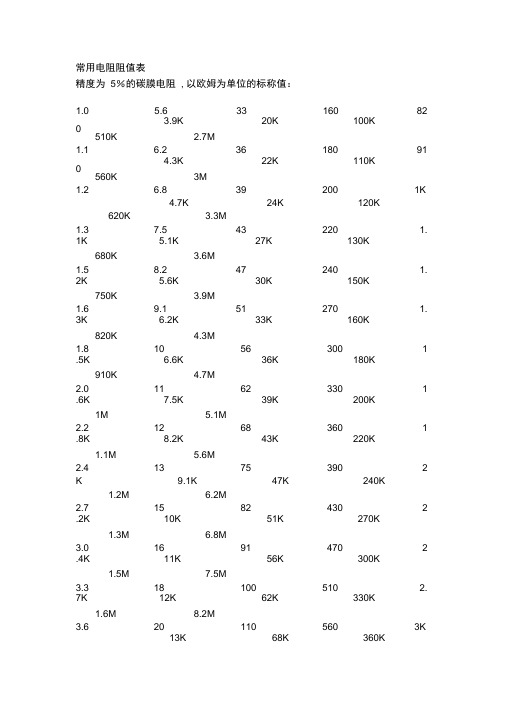
常用电阻阻值表精度为5%的碳膜电阻, 以欧姆为单位的标称值:1.0 5.6 33 160 82510K 3.9K2.7M20K 100K1.1 6.2 36 180 91560K 4.3K3M22K 110K1.2 6.8 39 200 1K4.7K 24K 120K620K 3.3M1.3 7.5 43 220 1.1K680K 5.1K3.6M27K 130K1.5 8.2 47 240 1.2K750K 5.6K3.9M30K 150K1.6 9.1 51 270 1.3K820K 6.2K4.3M33K 160K1.8 10 56 300 1.5K910K 6.6K4.7M36K 180K2.0 11 62 330 1.6K1M 7.5K5.1M39K 200K2.2 12 68 360 1.8K1.1M 8.2K5.6M43K 220K2.4 13 75 390 2 K 9.1K 47K 240K1.2M 6.2M2.7 15 82 430 2.2K1.3M 10K6.8M51K 270K3.0 16 91 470 2.4K1.5M 11K7.5M56K 300K3.3 18 100 510 2.7K1.6M 12K8.2M62K 330K3.6 20 110 560 3K13K 68K 360K3.9 22 120 620 3. 2K 15K 75K 390K 2M 10M4.3 24 130 680 3. 3K 16K 82K 430K2.2M 15M4.7 27 150 750 3. 6K 18K 91K 470K2.4M 22M5.1 30以欧姆为单位的标称值:精度为1%的金属膜电阻,10 33 100 3321K 3.32K 10.5K 34K 107K 357K10.2 33.2 102 340 1.0 2K 3.4K 10.7K 34.8K110K 360K10.5 34 105 348 1 .05K 3.48K 11K 35.7K 113K 365K10.7 34.8 107 350 1.0 7K 3.57K 11.3K 36K 115K 374K11 35.7 110 357 1 .1K 3.6K 11.5K 36.5K 118K 383K11.3 36 113 360 1 .13K 3.65K 11.8K 37.4K 120K 390K11.5 36.5 115 365 1.1 5K 3.74K 12K 38.3K 121K 392K11.8 37.4 118 374 1.1 8K 3.83K 12.1K 39K 124K 402K12 38.3 120 383 1 .2K 3.9K 12.4K 39.2K 127K 412K12.1 39 121 390 1 .21K 3.92K 12.7K 40.2K130K 422K12.4 39.2 124 392 1.2 4K 4.02K 13K 41.2K 133K 430K12.7 40.2 127 402 1.2 7K 4.12K 13.3K 42.2K137K 432K13 41.2 130 412 1 .3K 4.22K 13.7K 43K 140K 442K13.3 42.2 133 422 1.3 3K 4.32K 14K 43.2K 143K 453K13.7 43 137 430 1 .37K 4.42K 14.3K 44.2K 147K 464K14 43.2 140 432 1 .4K 4.53K 14.7K 45.3K 150K 470K14.3 44.2 143 442 1.4 3K 4.64K 15K 46.4K 154K 475K14.7 45.3 147 453 1.4 7K 4.7K 15.4K 47K 158K 487K15 46.4 150 464 1 .5K 4.75K 15.8K 47.5K 160K 499K15.4 47 154 470 1 .54K 4.87K 16K 48.7K 162K 511K15.8 47.5 158 475 1.5 8K 4.99K 16.2K 49.9K165K 523K16 48.7 160 487 1 .6K 5.1K 16.5K 51K 169K 536K16.2 49.9 162 499 1.6 2K 5.11K 16.9K 51.1K174K 549K16.5 51 165 510 1 .65K 5.23K 17.4K 52.3K 178K 560K16.9 51.1 169 511 1.69K 5.36K 17.8K 53.6K180K 562K17.4 52.3 174 523 1.7 4K 5.49K 18K 54.9K 182K 576K17.8 53.6 178 536 1.7 8K 5.6K 18.2K 56K 187K 590K18 54.9 180 549 1 .8K 5.62K 18.7K 56.2K 191K 604K18.2 56 182 560 1 .82K 5.76K 19.1K 57.6K 196K 619K18.7 56.2 187 562 1.8 7K 5.9K 19.6K 59K 200K 620K19.1 57.6 191 565 1.9 1K 6.04K 20K 60.4K 205K 634K19.6 59 196 578 1 .96K 6.19K 20.5K 61.9K 210K 649K20 60.4 200 590 2 K 6.2K 21K 62K215K 665K20.5 61.9 205 604 2.0 5K 6.34K 21.5K 63.4K220K 680K21 62 210 6192.1K 6.49K 22K 64.9K221K 681K21.5 63.4 215 620 2.1 5K 6.65K 22.1K 66.5K226K 698K22 64.9 220 634 2 .2K 6.8K 22.6K 68K232K 715K22.1 66.5 221 649 2.2 1K 6.81K 23.2K 68.1K237K 732K22.6 68 226 665 2 .26K 6.98K 23.7K 69.8K240K 750K23.2 68.1 232 680 2.3 2K 7.15K 24K 71.5K 243K 768K23.7 69.8 237 681 2.3 7 7.32K 24.3K 73.2K249K 787K24 71.5 240 698 2 .4K 7.5K 24.9K 75K 255K 806K24.3 73.2 243 715 2.4 3K 7.68K 25.5K 76.8K261K 820K24.7 75 249 732 2 .49K 7.87K 26.1K 78.7K 267K 825K24.9 75.5 255 750 2.5 5K 8.06K 26.7K 80.6K270K 845K25.5 76.8 261 768 2.6 1K 8.2K 27K 82K 274K 866K26.1 78.7 267 787 2.6 7K 8.25K 27.4K 82.5K280K 887K26.7 80.6 270 806 2.7 K 8.45K 28K 84.5K 287K 909K27 82 274 8202.74K 8.66K 28.7K 86.6K294K 910K27.4 82.5 280 825 2.8 K 8.8K 29.4K 88.7K 300K 931K28 84.5 287 845 2 .87K 8.87K 30K 90.9K 301K 953K28.7 86.6 294 866 2.9 4K 9.09K 30.1K 91K309K 976K29.4 88.7 300 887 3.0 K 9.1K 30.9K 93.1K 316K 1.0M30 90.9 301 909 3.01K 9.31K 31.6K 95.3K 324K 1.5M30.1 91 309 910 3.09K 9.53K 32.4K 97.6K 330K 2.2M30.9 93.1 316 931 3.1 6K 9.76K 33K 100K 332K31.6 95.3 324 953 3.2 4K 10K 33.2K 102K 340K电阻本身的阻值常用的有161 种1,1.1 ,1.2 ,1.3 ,1.5 ,1.6 ,1.8 2,2.2 ,2.4 ,2.7 ,3,3.3 , 3.6 ,3.94.3 ,4.75.1 ,5.66.2 ,6.87.58.29.110,11,12,13,15,16,1820,22,24,2730,33,36,3943,4751,5662,6875 82,81100,110,120,130,150 ,160,180 200,220,240,270300,330,360,390430,470510,560620,6807508209101K,1.1K,1.2K,1.3K,1.5K,1.6K,1.8K 2K,2.2K,2.4K,2.7K3K,3.3K,3.6K,3.9K4.3K,4.7K5.1K,5.6K6.2K,6.8K,7.5K8.2K9.1K10K,11K,12K,13K,15K,16K,18K 20K,22K,24K,27K30K,33K,36K,39K43K,47K51K,56K62K,68K75K82K91K100K,110K,120K,130K,150K,160K,180K200K,220K,240K,270K,300K,330K,360K,390K430K,470K510K,560K620K,680K750K,820K910K1M,1.1M,1.2M,1.3M,1.5M,1.6M,1.8M2M,2.2M,2.4M,2.7M3M,3.3M,3.6M,3.9M4.4M,4.7M几种常用电位器型号与规格1.有机实芯电位器由导电材料与有机填料、热固性树脂配制成电阻粉,经过热压,在基座上形成实芯电阻体。
铁氧体参数及国内外牌号对照表
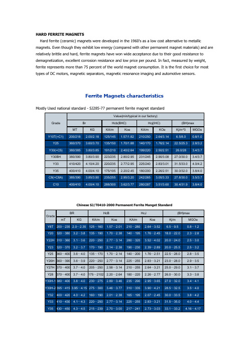
HARD FERRITE MAGNETSHard ferrite (ceramic) magnets were developed in the 1960's as a low cost alternative to metallic magnets. Even though they exhibit low energy (compared with other permanent magnet materials) and are relatively brittle and hard, ferrite magnets have won wide acceptance due to their good resistance to demagnetization, excellent corrosion resistance and low price per pound. In fact, measured by weight, ferrite represents more than 75 percent of the world magnet consumption. It is the first choice for most types of DC motors, magnetic separators, magnetic resonance imaging and automotive sensors.Ferrite Magnets characteristicsMostly Used national standard - SJ285-77 permanent ferrite magnet standardChinese SJ/T0410-2000 Permanent Ferrite Manget StandardIn MMPA(0100-87) standardRing shape size(mm) D×d×HФ115×45×5~23 Ф200×86×5~27 Ф70×32×3~17 Ф115×43×5~23 Ф200×83×5~27 Ф70×30.5×3~17 Ф115×45×5~23 Ф200×86×5~27 Ф70×32×3~17 Ф115×57×5~23 Ф200×95×5~27 Ф70×56×3~17 Ф115×58.7×3~23Ф200×100×5~27 Ф70×40×3~17 (elliptical)Ф115×60×5~23 Ф200×110×5~27 Ф71×40×3~17 Ф115×67×5~23 Ф200×120×5~27 Ф71×30.5×3~17 Ф115×80×5~23 Ф206×88.9×5~30 Ф71×32×3~17 Ф121×45×5~24 Ф206×89×5~30 Ф72×30.5×3~16 Ф121×57×5~24 Ф206×118×5~30 Ф72×32×3~16 Ф121×60×5~24 Ф210×86×5~30 Ф72×38×3~16 Ф121×65×5~24 Ф210×118×5~30 Ф72×40×3~16NdFeBKnown as third generation of Rare Earth magnets, Neodymium Iron Boron (NdFeB) magnets are the most powerful and advanced commercialized permanent magnet today. Since they are made from Neodymium, one of the most plentiful rare earth elements, and inexpensive iron, NdFeB magnets offer the best value in cost and performance.NdFeB magnets are available in both sintered and bonded forms. Sintered NdFeB offers the highest magnetic properties (28 MGOe to 50 MGOe) while Bonded NdFeB offers lower energy properties. Although bonded magnets do not possess magnetic properties as advanced as those of sintered magnets, they can be made in shapes and sizes that are difficult to achieve with sintering.A variety of coatings can be applied to the magnets' surface to overcome the principle drawback of neodymium-based magnets, their tendency to corrode easily.Grade Max. EnergyProductRemanence Coercive Force Rev. Temp.Coeff.CurieTemp.WorkingTemp. (BH)max B r H c H ci B d H d T c T w MGOe kJ/m3kG mT kOe kA/m kOe kA/m%/°C%/°C°C°CN3331-33247-26311.30-11.701130-1170>10.5>836>12>955-0.12-0.6031080 N3533-36263-28711.70-12.101170-1210>10.9>868>12>955-0.12-0.60310801.Licensed Products by SSMC-MQ - ISO 9002 Quality Standard Certified2.The above-mentioned data of magnetic parameters and physical properties are given at room temperature.3.The maximum service temperature of magnet is changeable due to the ratio length and diameter and enviromental factors.4.Special properties can be achieved with custom method.Physical and Mechanical PropertiesMax Working Temperature。
JAQUET FT 3000 速度测量系统 说明书

FT 3000 速度测量系统3通道速度控制和超速保护FT 3000系统文档:• FT 3000操作手册•传感器操作手册• 19 ¨机架说明•总体功能说明•系统配置•接线图• IEC 61508认证JAQUET科技集团•Thannerstrasse 15 • 4009 Basel • Switzerland电话: +41 (0)61 306 8822 •传真+41(0)613068818•***************•杰凯特科技集团上海办事处上海市浦东南路379号金穗大厦24Q座377E-63917操作手册版本 4.00 2004年12月20日FT 3000目录1 冗余超速保护系统的概念:............................................... .................................................. (5)2 安全警告 ................................................................................... ....... .. (7)3 应用.................................................................................. ............ . (7)4 结构 ........................................................................................... ............. . (7)5 前面板说明 .......................................................................... ...................... . (8)3024....................................................... ................................................... (8)5.1 FTFU5.2 FTV............................................... ................................. (8)30903072................................. ................................................ .. (9)5.3 FTK5.4 FTW 3013...................................... ............. . (9)............................... .................. .. (10)5.5 FTBU30346 技术规范 ......................................... ....... (11)6.1 统计数据.................................................. .... . (11)6.2 IEC技术规范:......................... . (11)61508-2-36.3 超速保护系统技术数据........................ (11)6.4 跳机链控制卡技术数据......................................... (17)7 工作原理....................................................... ......................... . (18)7.1 测量系统.............................................. ....... .. (18)7.2 测量原理............................................. ........... .. (18)7.2.1 测量数值标准化................................ ....................... (18)7.2.2 速度监控器......................................... ................ . (18)7.2.3 频率测量(周期测量原理) ....................... .................................................. . (18)7.2.4 加速度测量............................................. ................... (20)7.2.5 限值控制..................................................................... ........ (22)7.2.6 限值时间控制................................... ........ . (22)7.3 监控功能................................................................... ............. .. (22)7.3.1 电源............................................................ ....... (22)7.3.2 内电压监控................................................... ......................... (22)7.3.3 传感器监控.................................................... .... .. (22)7.3.4 系统监控.......................................................... ........ . (23)7.3.5 模块OK信息.................................................. ...... (23)7.3.6 故障状态...................................................... .. (23)7.4 旋转方向鉴别器..................................................................... . (23)7.5 继电器控制........................................................................ .... .. (23)7.6 测试频率发生器............................................................. ............... .. (24)7.7 测试................................................. ... . (24)7.8 频率输出.............................. ......................... (24)7.9 指示灯测试................................ . . (25)7.10 信息确认................................... ................................... . (25)7.11 二进制输入............................ ....... .. (25)7.12 参数录入................................... ................. . (25)7.13 信号监控................................... .................. (25)8 安装 ......................................... ......................... . (27)8.1 概述.......................................................... . (26)61508-2-3规定安装标准....... ............................. .. (26)8.2 IEC9 参数设置与操作 ......................................... ................................................ .. (28)9.1 软件概念................................................. ................ (28)9.1.1 操作参数清单................................ ................... .. (28)9.1.2 配置参数清单............................... ............................. .. (28)9.1.3 维修参数清单................................ ........................................... . (30)通讯.................................................. ...................... . (30)9.2 PC系统要求........................................... ......................... (30)9.2.1 PC软件安装.............................................. ...................... . (30)9.2.2 PC9.2.3 优化设置.................................................. ........... (31)9.2.4 显示间隔设置.............................................. ........................ (31)9.2.5 配置参数保护..................................................... (31)9.2.6 操作参数保护.................................................... ................................ (31)9.2.7 参数的读取与写入.......................................... ...................................................... .. (31)9.2.8 参数打印...................................................................... ................... . (31)9.2.9 当前测量数据显示......................................................... (31)9.3 参数设置............................................................................... ...................... (32)9.3.1 系统设置........................................................... ................... (32)9.3.2 传感器监控器............................................... ..... .. (33)9.3.3 模拟输出.......................................................... .............. (33)9.3.4 限值.................................................................. .................. .. (33)9.3.5 测试值..................................................... ........... (34)9.3.6 参数权限................................................. ................. (34)9.3.7 口令........................................................... .................. .. (34)9.4 运行情况.......................................................... ...................... (34)9.4.1 接通电源............................................. ..... (34)9.4.2 测量..................................................... ......................... .. (35)9.4.3 传感器故障响应................................. (35)9.4.4 系统报警情况........................................ ....................................... .. (35)9.4.5 停电响应............................................. .................................... (35)9.5 频率测量校准.............................................. .............................................. . (35)9.5.1 校准工具................................................. ............. .. (36)9.5.2 精确度影响因素..................................... ......................... (36)9.5.3 校准规则............................................... ...................... (36)9.6 传感器监控器校准......................................... ......................... . (37)9.6.1 精确度影响因素................................... ........................ (37)9.6.2 校准规则................................................. ............................... .. (37)10 机械结构.............................................................. ............................................. .. (38)11 电路说明............................................................... ........................... (40)11.1 FTFU 3024 主板与输入卡...................................... ........................ . (40)11.1.1 频率测量.......................................................... ........................... .. (40)11.1.2 速度监控器...................................................... ......... .. (40)11.1.3 微控制器........................................................ .............. .. (40)11.1.4 电源................................................................... ..... (40)11.1.5 复位与非屏蔽中断 (NMI) ............................. ............................ .. (41)11.1.6 输入放大器..................................................... .... . (41)11.1.7 传感器监控................................................. ............ . (41)11.1.8 模块监控...................................................... ................ . (42)11.1.9 继电器输出 (42)11.1.10 界限控制器指示灯.................................... . (42)11.1.11 频率发生器.................................................. ................... . (42)11.1.12 频率输出.................................................... .................. (42)11.1.13 二进制输入.................................................... ... .. (42)11.1.14 测试................................................................. ... . (42)11.1.15 旋转方向鉴别器......................................... .................................. .. (43)11.1.16 指示灯测试.................................................... .. (43)11.2 FTW 3013 – 电流卡.............. ............................................... . (43)11.2.1 电源............................................................... .... . (43)11.2.2 模拟输出......................................................... .......... .. (43)11.3 FTV 3090继电器卡.............................................. ..................................... .. (43)11.3.1 电源................................................................... ....... . (43)11.3.2 继电器输出.................................................... ...... (43)11.4 FTK 3072 通讯卡................................................... .............. . (43)11.4.1 机架主线........................................................ ... (43)232 接口....................................................................... ..... . (44)11.4.2 RS12 维护.................................................................................. .. (44)12.1 定期测试................................................................... .......... (45)12.1.1 说明.............................................................. .............. (45)12.1.2 IEC61508-2-3 技术规范................................. .......... (45)12.2 故障排除:................................................................. ............. . (46)12.2.1 超速保护流程...................................................... ................... .. (46)12.2.2 调机链流程 : ..................................................... ....................... . (47)61508-2-3 技术规范.............................. ............ . (47)12.2.3 IEC12.3 模块交换: .............................................................. .................... .. (47)12.3.1 概述......................................................................... ...... . (47)61508-2-3 技术规范:.................................. ........ . (48)12.3.2 IEC13 储存................................................................................ ................... (48)14 质保................................................................................. ................ . (48)15 图示.................................................................................................... .. (48)1.冗余超速保护系统的概念:和/或19"机架端子上接地。
FPGA可编程逻辑器件芯片XQR2V3000-4CG717V中文规格书
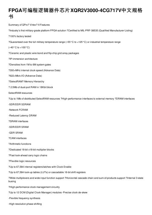
FPGA可编程逻辑器件芯⽚XQR2V3000-4CG717V中⽂规格书Summary of QPro? Virtex?-II FeaturesIndustry’s first military-grade platform FPGA solution Certified to MIL-PRF-38535 (Qualified Manufacturer Listing)100% factory testedGuaranteed over the full military temperature range (–55°C to +125°C) or industrial temperature range(–40°C to +100°C)Ceramic and plastic wire-bond and flip-chip grid array packagesIP-immersion architectureDensities from 1M to 6M system gates300+MHz internal clock speed (Advance Data)622+Mb/s I/O (Advance Data)SelectRAM Memory Hierarchy2.5Mb of dual-port RAM in 18Kbit blockSelectRAM resourcesUp to 1Mb of distributed SelectRAM resources High-performance interfaces to external memory DRAM interfaces-SDR/DDR SDRAM-Network FCRAM-Reduced Latency DRAMSRAM interfaces-SDR/DDR SRAM-QDR SRAMCAM interfacesArithmetic functionsDedicated 18-bit x18-bit multiplier blocksFast look-ahead carry logic chainsFlexible logic resourcesUp to 67,584 internal registers/latches with Clock EnableUp to 67,584 look-up tables (LUTs) or cascadable 16-bit shift registersWide multiplexers and wide-input function support Horizontal cascade chain and sum-of-products support Internal 3-state busingHigh-performance clock management circuitryUp to 12 DCM (Digital Clock Manager) modules -Precise clock de-skew-Flexible frequency synthesis-High-resolution phase shifting16 global clock multiplexer buffersActive interconnect technologyFourth-generation segmented routing structurePredictable, fast routing delay, independent offanoutSelectIO-Ultra TechnologyUp to 824 user I/Os19 single-ended and six differential standardsProgrammable sink current (2mA to 24mA) per I/ODigitally Controlled Impedance (DCI) I/O: on-chip termination resistors for single-ended I/O standards PCI compliant (32/33MHz) at 3.3VDifferential signaling622Mb/s Low-Voltage Differential Signaling I/O (LVDS) with current mode driversBus LVDS I/OLightning Data Transport (LDT) I/O with current driver buffersLow-Voltage Positive Emitter-Coupled Logic(LVPECL) I/OBuilt-in DDR input and output registersProprietary high-performance SelectLinkTechnology-High-bandwidth data path-Double Data Rate (DDR) link-Web-based HDL generation methodology ?Supported by Xilinx Foundation Series? and Alliance Series? Development SystemsIntegrated VHDL and Verilog design flowsCompilation of 10M system gates designsInternet Team Design (ITD) toolQPro Virtex-II 1.5V Platform FPGAsDS122 (v3.0) April 7, 2014Product SpecificationSlices LUTs Flip-FlopsMULT_ANDsArithmetic & Carry ChainsSOP Chains Distributed SelectRAM Shift Registers TBUF 488822128bits128bits2Table 17:Virtex-II Logic Resources Available in All CLBsDevice CLB Array: Row x Column Number of Slices Number of LUTs Max Distributed SelectRAM or Shift Register (bits) Number of Flip-Flops Number of Carry Chains (1)Number of SOP Chains (1)XQ2V100040 x 325,12010,240163,84010,2406480XQ2V300064 x 5614,33628,672458,75228,672112128XQ2V6000 96 x 8833,79267,5841,081,34467,584176192Each block SelectRAM cell is a fully synchronous memory, as illustrated in Table 31, page 38. The two ports have independent inputs and outputs and are independently clocked.Port Aspect RatiosT able 20 shows the depth and the width aspect ratios for the 18Kbit block SelectRAM. Virtex-II block SelectRAM also includes dedicated routing resources to provide an efficient interface with CLBs, block SelectRAM, and multipliers. Table 19:Dual-Port Mode ConfigurationsPort A 16K x 116K x 116K x 116K x 116K x 116K x 1Port B16K x 18K x 24K x 42K x 91K x 18512x 36Port A8K x 28K x 28K x 28K x 28K x 2Port B8K x 24K x 42K x 91K x 18512x 36Port A4K x 44K x 44K x 44K x 4Port B4K x 42K x 91K x 18512x 36Port A2K x 92K x 92K x 9Port B 2K x 91K x 18512x 36Port A 1K x 181K x 18Port B 1K x 18512x 36Port A 512x 36Port B512x 36Figure 31:18 Kbit Block SelectRAM in Dual-Port ModeTable 20:18Kbit Block SelectRAM Port Aspect RatioWidth Depth Address Bus Data Bus Parity Bus116,384ADDR[13:0]DA T A[0]N/A 28,192ADDR[12:0]DA TA[1:0]N/A 44,096ADDR[11:0]DA TA[3:0]N/A 92,048ADDR[10:0]DA TA[7:0]Parity[0]181,024ADDR[9:0]DA TA[15:0]Parity[1:0]36512ADDR[8:0]DA TA[31:0]Parity[3:0]。
FQT7N10中文资料

150℃ 25℃
※ Notes : 1. V = 0V 2. 25G0Sμ s Pulse Test
10-1 0.2 0.4 0.6 0.8 1.0 1.2 1.4 1.6 1.8 2.0 V , Source-Drain Voltage [V]
SD
Figure 4. Body Diode Forward Voltage Variation vs. Source Current and Temperature
IS
Maximum Continuous Drain-Source Diode Forward Current
--
--
1.7
A
ISM
Maximum Pulsed Drain-Source Diode Forward Current
--
--
6.8
A
VSD
Drain-Source Diode Forward Voltage VGS = 0 V, IS = 1.7 A
VGS(th) RDS(on)
Gate Threshold Voltage
Static Drain-Source On-Resistance
gFS
Forward Transconductance
VDS = VGS, ID = 250 µA
2.0 --
VGS = 10 V, ID = 0.85 A
-- 0.28
D
S
G SOT-223
FQT Series
Absolute Maximum Ratings TC = 25°C unless otherwise noted
Symbol VDSS ID
IDM VGSS EAS IAR EAR dv/dt PD
磁芯材质对照表

磁芯材质对照表・NCD和其它厂商铁氧体材料牌号对照表• NCD和其它厂商铁氧体材料牌号对照表・NCD和其它厂商铁氧体材料牌号对照表-3材料总览功率铁氧体材料LP2・导磁率Vs.频率特性・功率损耗Vs.温度特性FrequcmytkHEj功率铁氧体材料LP3特性 符号 单位LP3Characteristics SymbolUnit初始磁导率 Initial permeability □ i -2300±25% 相对损耗因数Relative loss factor tan6/uiX10-6 <4饱和磁通密度 Bs mT25℃ 500 Saturation flux density 1194A/m100℃ 390 剩磁 Remanence Br mT 130 矫顽力 Coercivity Hc A/m 13idDnnTJDtJ(teiiT12D・功率损耗Vs.频率特性'—I100mTSOmTLP2 1DOT二・导磁率Vs.温度特性・导磁率Vs.频率特性10・功率损耗Vs.温度特性1m・功率损耗Vs.频率特性F叫厕期1^|相对损耗因数Relative loss factor tan6/ui X10-6<3饱和磁通密度BsmT 25℃490Saturation flux density1194A/m100℃380剩磁 Remanence Br mT110矫顽力 Coercivity Hc A/m10功率损耗Pc kW/m325℃Power loss80℃60 (f=25kHz,B=200mT)100℃50功率损耗Pc kW/m325℃600Power loss80℃400 (f=100kHz,B=200mT)100℃350居里温度 Curie temperature Tc℃三200密度 Density d kg/m3X103 4.8・导磁率Vs.频率特性Ui Vs. Frequency・功率损耗Vs.温度特性1G-1t f10Frequency kHz)・功率损耗Vs.频率特性・高磁导率铁氧体材料・导磁率Vs.温度特性“峥1a•阻抗Vs.频率特性EE磁芯价格:¥面议Al:1kHz,0.5mA,100TsPc:100kHz,200mT,100°C100kHz,100mT,100°C(*)。
N700说明书
2.
正面图
底面图
顶部图
侧面图
背面图
按键
功能描述
电源键:长按3秒用于开机和关机;开机状态下短按可关闭屏幕背光。
音量键:通话时调节通话音量;待机状态调节本机音量。
主页键:在任何界面下点击,退出功能,回到待机界面;在任何界面下长按,出现最近使用的6个菜单选项。
选项键:点击获取更多选项。
返回键:点击返回到上一级菜单
飞机上:无线装置会对飞机飞行造成干扰,请遵守所有限制。
加油时:请勿在加油站、燃料、化学品附近使用本设备。
避免干扰爆破:在爆破现场应关闭设备,并遵守任何相关的规定。
干扰:所有无线设备都可能会收到干扰,影响性能。
原装配件:为了确保最佳性能,请使用原装配件与电池,请勿连接不兼容产品。
防水:本机不具备防水功能,请您注意防水,保持设备干燥。
1.关闭屏幕
您可以按【电源键】关闭屏幕以节省电量,防止误按。
2.开启屏幕
要开启屏幕,按电源键即可点亮屏幕。
为防止意外操作,您可以对设备和屏幕进行锁定。
1.锁定设备
短按【电源键】,请注意,若您在系统默认或者设定的锁屏时间之内对设备没有任何操作,设备将被自动锁定。
2.解锁设备
短按【电源键】,向右划动主屏中的解锁键解锁。
在主屏幕界面点击应用程序托盘,您可以访问所有的程序并对系统进行设置。
点击主屏幕托盘,您可以返回主屏幕界面。
您可以设置日期、时间、时区和格式。
在应用程序界面,点按设置>日期和时间。
日期和时间设置包括:自动,设置日期,选择时区,设置时间,使用24小时格式,选择日期格式。
自动选项在插入UIM/SIM卡后才能使用。
安全设置
MQ-7
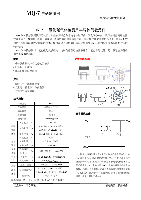
MQ-7 一氧化碳气体检测用半导体气敏元件MQ-7气体传感器所使用的气敏材料是在清洁空气中电导率较低的二氧化锡(SnO 2)。
采用高低温循环检测方式低温(1.5V 加热)检测一氧化碳,传感器的电导率随空气中一氧化碳气体浓度增加而增大,高温(5.0V 加热)清洗低温时吸附的杂散气体。
使用简单的电路即可将电导率的变化,转换为与该气体浓度相对应的输出信号。
MQ-7气体传感器对一氧化碳的灵敏度高,这种传感器可检测多种含一氧化碳的气体,是一款适合多种应用的低成本传感器。
特点 元件外形结构 *对一氧化碳气体有良好的灵敏度 *长寿命、低成本 *简单的驱动电路即可应用*家庭用气体泄漏报警器 *工业用一氧化碳气体报警器 *便携式气体检测器技术指标基本测试回路上图是传感器的基本测试电路。
该传感器需要施加2个电 压:加热器电压(V H )和测试电压(V C )。
其中 V H 用于为传 感器提供特定的工作温度。
V C 则是用于测定与传感器串联 的负载电阻(R L )上的电压(V RL )。
这种传感器具有轻微的 极性, V C 需用直流电源。
在满足传感器电性能要求的前提 下,V C 和V H 可以共用同一个电源电路。
为更好利用传感器的 性能,需要选择恰当的RL 值。
敏感体功耗(Ps )值可用计算下式:Ps=Vc 2×Rs/(Rs+R L )2产品型号 MQ-7产品类型 半导体气敏元件标准封装 塑封检测气体 一氧化碳检测浓度 10-1000ppmCO 标准电路条件回路电压 V c ≤10V DC加热电压 V H 5.0V±0.2V ACorDC (高) 1.5V ±0.1V ACorDC (低)加热时间 T L 60±1S (高)90±1S (低)负载电阻R L 可调标准测试条件下元件特性 加热电阻 R H 31Ω±3Ω(室温)加热功耗 P H ≤350mW敏感体表面电阻 R s 2K Ω-20K Ω(in100ppmCO) 灵敏度 S Rs(in air)/Rs(100ppmCO)≥5浓度斜率α≤0.6(R 300ppm /R 100ppm CO) 标准测试条件温度、湿度 20℃±2℃;65%±5%RH 标准测试电路 Vc:5.0V±0.1V ; V H (高): 5.0V±0.1V ; V H(低): 1.5V±0.1V 预热时间不少于48小时VcV HGNDR LV RL传感器电阻(Rs),可用下式计算: Rs=(Vc/V RL-1)×R LSO9001认证企业灵敏度特性 温/湿度的影响图1是传感器典型的灵敏度特性曲线。
EN中文版
铁路应用具有特殊防火性能铁路机车车辆电力和控制电缆第2-2部分:多芯交联橡胶绝缘电缆简介EN50264涉及到用于铁路车辆的系列电缆,该系列电缆属于采用无卤材料的护套以及无护套电缆。
该标准分为5部分:括减少环境温度和安装类型因素)见EN50343oEN50264中涉及的特殊测试方法见EN50305o第1部分“一般要求”对EN50264做出了更详尽的介绍,因此应与第2-2部分一起使用。
1.范围EN50264-2-2规定了对下列型号及额定电压下的单芯电缆的要求、结构及尺寸。
•300/500V屏蔽或无屏蔽电缆(lmm\ 1.5mm2和2. 5mm:, 2芯到40芯);•0. 6/lkV屏蔽或无屏蔽电缆(1.5mm:到50mm,, 2芯、3芯和4芯)。
注:并非每个类型都规定J'导线尺寸或线芯数目所有的电缆采用5类镀锡铜线,符合EN60228的规定,且为无卤绝缘和无卤护套。
这些电缆用于铁路机车固定布线,或者操作时会碰到极限挠度的布线。
要求连续导线温度不超过90°C,在5秒内,短路条件下最大温度为200°C。
发生火灾时,电缆在最大允许火焰传播(火焰蔓延),最大允许烟雾及有毒气体释放等方面具有特殊的性能。
EX50264-2-2应与第1部分“一般要求” 一起使用。
2.引用标准以下引用的文件对于实施本文件是必不可少的。
凡注日期的引用文件,最新版不适用于本标准。
不注日期的引用文件,其最新版(包括任何修订)适用于本标准。
EN10002-1金属材料一拉伸测试一室温条件下试验方法EN50264-1铁路应用一具有特殊防火性能铁路机车车辆动力和控制电缆第1部分:一般要求EN50266-2-4电缆在火焰条件下的通用试验方法一垂直安装的成束电线或电缆的垂直火焰蔓延试验第2-4部分:试验步骤一C类EN50266-2-5电缆在火焰条件下的通用试验方法一垂直安装的成束电线或电缆的垂直火焰蔓延试验第2-5部分:试验步骤一小电缆一D 类EN50305:2002铁路应用-具有特殊防火性能铁路机车车辆电缆-测试方法EX50334电缆芯线识别用符号标记EN60228 电缆的导体(IEC60228)EN60332-1-2电缆和光缆在火焰条件下的试验方法第1-2部分:单根绝缘电线电缆垂直火焰蔓延试验一lkW预混合火焰(IEC660332-1-2) EN608U-l-l:1995电缆和光缆绝缘和护套材料的一通用试验方法第1~1部分:一般应用一厚度和外形尺寸测量一机械性能试验(IEC60811-l-l:1993)EN60811-1-2:1995电缆绝缘和护套材料的一通用试验方法第1-2部分:一般应用一热老化试验 (IEC60811-l-2:1985+Al : 1989+corr.Mayl986)EN60811-1-3:1995电缆和光缆绝缘和护套材料的一通用试验方法第1-3部分:一般应用一密度测定方法一吸水试验一回缩试验(IEC60811-1-3:1993)EN60811-1-4:1995电缆和光缆绝缘和护套材料的一通用试验方法第1-4部分:一般应用一低温试验(IEC60811-1-4:1985+A11993+corr.May1986 ) EN60811-2-l:1998电缆和光缆绝缘和护套材料的一通用试验方法第2-1部分:一般应用一橡胶混合物测试方法一耐臭氧试验、热延伸试验和浸矿物油试验(IEC60811-2-1:1998)EN61034-2电缆在特定条件下燃烧的烟密度测定第2部分:试验步骤和要求(IEC61034-2)HD308电缆与软线的芯线标记3.定义EN50264-1的定义适用于木标准。
MXenes材料的光学特性及相关研究进展

Vol.42 2021年2月No.2 397~411[综合评述]CHEMICAL JOURNAL OF CHINESE UNIVERSITIES高等学校化学学报MXenes材料的光学特性及相关研究进展黄大朋,于浩海,张怀金(山东大学晶体材料国家重点实验室,晶体材料研究所,济南250100)摘要过渡金属碳化物、氮化物或碳氮化物(MXenes)具有丰富的元素组成和结构可调性,显示出丰富的物理化学性质和巨大的应用潜力.本文以此类材料的基本光学特性为基础,从光子发射、透明导电及储能、非线性光学、表面等离激元及拉曼增强、光热转化、光催化及光响应等光学相关领域展开分析和综述.并对此二维材料相关应用的未来发展及机遇作了简单评述,以期为进一步的研究提供参考.关键词MXenes;金属态;线性光学;非线性光学中图分类号O613;O734文献标志码A过渡金属碳化物、氮化物或碳氮化物(MXenes)材料是近几年新兴的二维(2D)材料,其丰富的元素组成和结构可调性赋予了其丰富的物理化学性质,并逐渐在2D材料家族中脱颖而出.MXenes材料的化学式为M n+1X n T x,其中M表示早期过渡金属Sc,Y,Ti,Zr,Hf,V,Nb,Ta,Cr,Mo或W,X表示碳和/或氮,通常n=1~3,T表示表面终端(主要是—OH,=O和—F),其下角x表示表面官能团的数量. 2D片层的厚度在1nm范围内,可以通过改变MXenes中的n从M2XT x到M3X2T x和M4X3T x来调控.通常MXenes是通过选择性腐蚀MAX相陶瓷的A元素而获得的,其中A是一组IIIA到VIA族元素.因此MXenes与MAX一样具有六方对称性,属于P63/mmc空间群.其中过渡金属(M)原子排列成一个近密排结构,X元素原子位于其八面体间隙位置.图1(A)~(C)描绘了211,312和413计量比的MAX相六方单胞.单胞由M6X八面体组成,如Ti6C,其与A元素层(例如Al、Si或Ge)交错分布.211,312和413MAX 相之间的区别在于分隔A层的M原子层数量不同.MAX相中M6X棱边共享的八面体基本构架与二元碳化物和氮化物MX是相同的.在312和413计量比的MAX结构中,一般有2个不同的M位点,分别是与A相邻的M(1)和不相邻的M(2).在413结构中,还存在2个非等效的X位,X(1)和X(2).在所有情况下,MX层彼此成对,并由充当镜像平面的A层分开,如图1(D)所示.MAX结构是各向异性的,晶格参数通常为a≈0.3nm和c≈1.3nm(211相),c≈1.8nm(312相)和c≈2.3~2.4nm(413相)[1~4].由于其独特的晶体结构以及外层过渡金属d轨道电子的贡献,多数MXenes通常表现为金属态或窄带隙半导体属性,并且外层过渡金属对于材料的能带结构和电子特性具有决定性作用,因此2D MXenes家族丰富的结构可调性及元素组合赋予了此类材料诸多新奇特性,如半金属态、拓扑绝缘态、半导体态以及铁磁性和反铁磁性[5~7].由于材料的光学响应与其结构和电子特性直接相关,比如带内及带间电子跃迁直接决定了材料的光学吸收及光子辐射行为,因此具有丰富可调性的MXenes材料在光学领域同样展现出极大潜力并吸引研究者在此领域展开研究和应用开发.目前,相关综述主要集中在MXenes材料制备及电化学等相关领域,而在光学及光电子器件相关领doi:10.7503/cjcu20200584收稿日期:2020-08-21.网络出版日期:2020-12-25.基金项目:国家自然科学基金(批准号:51890863,51632004)和山东省泰山学者基金资助.联系人简介:于浩海,男,博士,教授,主要从事光电功能晶体、激光技术与器件以及晶体物理方面的研究.E⁃mail:****************.cn张怀金,男,博士,教授,主要从事人工晶体生长和性能研究.E-mail:********************.cnVol.42高等学校化学学报域仍缺乏综合性概述与分析,因此本文重点考察此类二维晶体的光学特性及其相关应用,从基本光学特性出发,对其新近发现的新奇光学特性及应用展开分析和综述,主要涉及光子发射、透明导电及储能、非线性光学、表面等离激元及拉曼增强、光热转化、光催化及光响应等光学相关领域.1MXenes 材料的基本光学特征MXenes 的线性光学性质(如吸收、光致发光等)和非线性光学性质(如饱和吸收、非线性折射率等)高度依赖于其能带结构(如能带隙、直接/间接带隙、拓扑绝缘特性等),更具体地说,是依赖于线性和非线性介电函数(ε)的色散或折射率(n=εμ)的色散.Lashgari 等[8]利用全势线性缀加平面波方法(FLAPW )和随机相位近似(RPA )方法计算了二维Ti n +1X n MXene 化合物(Ti 2C ,Ti 2N ,Ti 3C 2和Ti 3N 2)的光学响应[复介电函数(ε)、反射、吸收和电子能量损失函数],介电函数的虚部Im ε计算如下:Im ε[interband ]ij (ω)=h 2e 2πm 2ω2∑n∫d k ψC n k p i ψV n k ψV n k p j ψC n k δ(E C n k -E V n k -ω)(1)式中:h ,e ,m 分别为普朗克常数、电子电荷和电子有效质量;ψV n k 对应于占据的价带能级;ψC nk 代表第一布里渊区k 点上的空导带能级;E C n k 和E V nk 分别代表未占据的导带和占据的价带能态;ω是相互作用电磁波的频率.通过反向变换,可以得到相应的实部为:Re ε[interband ]ij(ω)=δij +2πP ∫0∞ω′Im εij (ω)(ω′)2-ω2(2)式中:P 为主值积分.带内跃迁的贡献分别为:Im ε[intraband ]ij (ω)=Γω2pl ,ij ω(ω2+Γ2)(3)Re ε[intraband ]ij (ω)=1-ω2pl ,ij ω(ω2+Γ2)(4)式中:ω2p =ne 2ε0m ,ω2p 表示等离子体频率;n 表示自由载流子或电子浓度;m 表示有效电子质量;Γ表示Drude 模型中的阻尼/损耗项.因此,带间和带内电子跃迁贡献的完整介电函数可以写成:ε(ω)=ε[intraband ](ω)+ε[interband ](ω)(5)单层Ti n +1X n (X=C ,N ,n =1,2)具有六方空间群对称性,其中包括三原子层Ti 2X 和五原子层Ti 3X 2.由于这种对称性,在与晶体c 轴平行(E ||x )和垂直(E ||z )的电场激励下,复介电函数张量只有3个非零分Fig.1Crystal structures of the 211(A),312(B),and 413(C)MAX phases and high⁃angle annular dark field TEM image,acquired along the [11-20]zone axis of Ti 3SiC 2,showing the twinned structureand the resulting characteristic “zig⁃zag ”stacking of MAX phases(D)[4]Copyright 2010,Elsevier.398No.2黄大朋等:MXenes 材料的光学特性及相关研究进展量:εxx (ω)=εyy (ω)和εzz (ω).图2(A )描绘了相应的介电张量.介电函数虚部Im ε的峰归属于不同带内和带间电子跃迁的直接贡献.介电函数实部Re ε可以通过Kramers -Kronig 关系获得,如图2(A )中插图所示.利用频率依赖的复介电函数,可以计算出反射和吸收等重要的光学参数.吸光度(A )与填充的价带到空导带能级的带间跃迁的总贡献成正比[图2(B )].由于特殊的合成过程,单层MXenes 的最外层过渡金属原子通常被官能团(如—F 、—O 和—OH )钝化.最近的研究表明,表面功能化可以在很大程度上影响MXenes 的能带结构和电子特性[9~11].MXenes 材料的独特属性(电子输运、电容等)可以通过调节表面官能团来调整.Berdiyorov [12]通过计算模拟讨论了功能化对Ti 3C 2T 2-MXene 光学性质的影响.材料系统中频率依赖的复介电常数可以由材料的电极化率导出,即ε(ω)=ε1+ε2=1+χ(ω)(ε1与ε2分别为介电常数的实部和虚部).如图3(A )和(B )所示,计算所得介电函数随官能团和光谱范围的变化而显著变化.利用介电函数还可以得出Ti 3C 2T 2的频率相关折射率n 和消光系数k [图3(C )和(D )]以及吸收光谱[图3(E )和(F )].在吸收光谱中可以观察到官能团之间的显著差异,特别是在低光子能量区,显示出表面官能团对于最终性质的重要影响.目前对于MXenes 材料介电函数的结论多停留在理论层面,因此下一步应该注重在实验上实现介电函数的表征和调控,尤其是单层或少层MXenes 样品,这样可以更好地指导实验设计和应用开发.Fig.2Calculated imaginary part of the dielectric function(A)(inset shows the real part)and absorptioncoefficient for Ti 3C 2⁃MXene(B)[8]The two nonzero components of the dielectric tensor εxx (ω)and εzz (ω)for electric field perpendicular(E ||x )and parallel(E ||z )to c ⁃axis are represented by the solid red and dashed blue line.Copyright 2014,Elsevier.Fig.3Real(ε1)(A)and imaginary(ε2)(B)part of dielectric function as a function of photon energyfor Ti 3C 2T 2⁃MXene;refractive index,n (C),and the extinction coefficient,k (D),as a functionof photon energy for Ti 3C 2T 2MXene and absorption spectra of Ti 3C 2T 2⁃MXene for small(E)and larger(F)range of photon energy [12]Ti 3C 2:solid⁃black curves;Ti 3C 2F 2:dashed⁃red curves;Ti 3C 2O 2:dotted⁃green curves;Ti 3C 2(OH)2:dash⁃dotted⁃bluecurves.Shaded area shows the visible range of the spectrum.Copyright 2016,American Institute of Physics.399Vol.42高等学校化学学报2MXenes 材料在光学相关领域中的研究进展2.1MXenes 材料的光发射性能及应用MXenes 材料通常具有金属态属性,以Ti 3C 2-MXene 为例,其导带与价带在布里渊区沿Γ-M 和M⁃K 方向合并,因此此能带结构使其成为原子级金属材料.使用常规湿化学刻蚀法制备的Ti 3C 2-MXene 中通常还带有表面终端,比如—F ,—O ,—OH 等.这些表面基团对其能带结构可能产生轻微的修饰作用,使其带隙打开至约0.1eV ,但仍保持较高的电导率[13].其独特的能带结构和通常情况下的间接带隙(0~0.1eV )特征,使其在可见光或紫外光激发下产生的带边电子-空穴对并未产生可见或红外的光子发射或者光子发射率极低[14].这种激子相关的光致发光(PL )在过渡金属双硫属化合物(TMDs )中是非常典型的,但在MXenes 材料原始状态下并未实现.2019年,Zhang 等[15]通过调控Ti 3C 2-MXene 表面TiO 2的参与,在大片层Ti 3C 2-MXene 中观察到了光致发光现象并表征了其激发波长依赖特性.并且在一定的表面TiO 2修饰量下获得了可调的光发射红移现象[图4(A )和(B )].另一种使MXenes 材料获得光发射能力的方法是利用量子限域效应使材料的能带隙打开和能带结构发生改变.当MXenes 材料尺寸减小到几纳米并以量子点的形态存在时[16],其能带结构向直接带隙的转变以及带隙的打开能够允许电子辐射跃迁,在可见光和紫外光激发下可以表现出明显的、可调节的可见光发射[图4(C )和(D )].MXenes 这一光学特征与其金属态能带结构形成鲜明对比,因此对MXenes 材料光发射性能的研究主要是集中在MXenes 量子点(MQDs )状态下的光学行为.通常,MQDs 在约260,310和350nm 处可观察到3个吸收峰,这取决于其粒径和组成.光致发光谱带高度依赖于激发波长,随着激发波长从340nm 到440nm 的变化,PL 光谱相应地从400nm 到600nm 发生变化.Xue 等[16]在水热过程中通过改变温度制备了平均尺寸分别为2.9,3.7和6.2nm 的Ti 3C 2-MQDs.在320nm 波长的光激发下,最大量子产率可达9.9%.同时他们还发现,光致发光强度与溶液pH 值无关,这可能是由于—NH 基团对MQDs 高度的表面钝化所致.Niu 等[17]发现溶剂对裁剪所得Ti 3C 2-MQDs 的量子产率和荧光寿命有很大影响.在二甲基甲酰胺(DMF )溶剂环境中所得MQDs 的量子产率最高可达10.7%.在二甲基亚砜(DMSO )溶剂环境中所得MQDs 的荧光寿命在3种溶剂(DMF 、DMSO 和乙醇)中是最长的,为4.7ns [图5(A )].鉴于DMSO溶剂Fig.4Schematic of TiO 2clusters interspersed throughout the Ti 3C 2⁃MXene flake,and the diagrams of PLtransitions at perfect Ti 3C 2⁃MXene and defective TiO 2(A),PL spectra of Ti 3C 2⁃MXene without(left)and with modification(right)at the excitation wavelengths of 405nm,532nm and 632.8nm(B)[15],schematic diagram of preparation of MXenes quantum dots(MQDs)(C)and UV⁃Vis spectra(solidline),PLE(dashed line),and PL spectra(solid line,λex =320nm)of MQD in aqueous solutions(D)[16](A,B)Copyright 2019,Elsevier.(C,D)Copyright 2017,John Wiley and sons.400No.2黄大朋等:MXenes 材料的光学特性及相关研究进展较大极性和较强氧化性的特点,此处相对较长的荧光寿命是由MQDs 较多的氧化位点和小的尺寸所致.此外,他们还发现Fe 3+在DMF 中会对MQDs 产生独特的荧光猝灭效应[图5(B )],而在其它两个溶剂中并不明显.在氨水溶液中通过类似的水热过程,Huang 等[18]发现制备的V 2C -MQDs 具有显著钝化的表面,其PL 量子产率高达15.9%,远高于非钝化量子点.在所获宽带发射谱基础上,借助纳秒脉冲强激发下触发的非线性散射机制,实现了红、绿、黄、蓝4色同时发射的白色激光[图5(C )和(D )].Lu 等[19]通过溶剂热方法,使用油酸作为表面修饰剂制得了Ti 3C 2-MQDs ,其在紫外光激发下可以表现出白光效果,使用近红外飞秒激光激发还可以产生双光子白光发射,并且MQDs 的荧光可以在外部施加压力调节下实现冷白到暖白光的转变[图5(E )].另外,Ti 3C 2-MXene 与乙二胺在高压釜中于160℃反应12h 可以制备出氮掺杂的Ti 3C 2-MQDs [20][图5(F )],其光致发光量子产率可达18.7%,荧光寿命为7.06ns.所制的氮掺杂的Ti 3C 2-MQDs 在Na +,Mg 2+,Cu 2+,K +,Mn 2+,Zn 2+,Ca 2+,Al 3+,Ce 3+,Cu +和Ni 2+离子中表现出对Fe 3+的选择性荧光猝灭特性,因此可作为超灵敏Fe 3+探针,检出限可达100µmol/L.Chen 等[21]发现Ti 3C 2-MQDs 的发光强度对表面缺陷的去质子化非常敏感,增加MQDs 溶液的pH 值可显著降低MQDs 的zeta 电位、460nm 处的吸光度以及PL 发射强度和寿命.通过使用pH 不敏感的[Ru (dpp )3]Cl 2作为发射参比,Ti 3C 2-MQDs 可以用作比率pH 传感器来定量监测细胞内pH 值.Wang 等[22]在其所制样品中发现Ti 3C 2-MQDs 的光致发光在pH 值升高至6以上后波长和强度均无明显变化,而在低pH 值(2~5)时,光致发光强度则显著降低.近来,Nb 2C -MQDs 也被开发出来,并通过S 、N 掺杂获得了19%的发光效率[23],其在被作为荧光探针用于3D 脑组织成像时获得了较好的效果.Yang 等[24]也论证了Nb 2C -MQDs 优异的光稳定性和生物兼容性,为新型传感/成像纳米荧光团的应用研究提供了一种新的方案.另外电化学发光(ECL )正成为一种越来越强大的生物和环境诊断分析工具.在Ti 3C 2-MQDs 中也观察到了高效的ECL行为,但其机制因溶剂不同而不同[17,25].可见,MQDs 是当前MXenes 材料在光学领域应用的关键形态,而进一步地应用开发仍需要充分认识MQDs 的发光机理,以获得更有效的发光调控和实现发光效率提升来满足不同场合下的应用需求.Fig.5Fluorescent lifetime of s⁃MQDs(a),f⁃MQDs(b),and e⁃MQDs(c)(A),PL intensity of f⁃MQDs excited at377nm upon addition of Fe 3+ions ranging from 0to 750×10−6mol/L(B)[17],emission spectra from theV 2C MQD colloid for different pump fluences(C),plot of the calculated CIE coordinates of emissionspectra under different pumping fluence(D)[18],schematic illustration of the emission,and under theconditions of high pressure(E)[19],and fluorescence emission spectra of the prepared N⁃MQDs(160℃)at different excitation wavelengths and photographs under UV light(365nm)(inset)(F)[20](A,B)Copyright 2018,John Wiley and sons;(C,D)Copyright 2019,John Wiley and sons;(E)Copyright 2019,John Wiley and sons;(F)Copyright 2018,Royal Society of Chemistry.401Vol.42高等学校化学学报2.2MXenes 材料的线性光学传输性能及透明导电和储能应用由于费米能级附近高的电子态密度,MXenes 材料展现出不同寻常的光电子传输性能,因此在光电子应用中被寄予厚望.如前所述,MXenes 材料的电子能带结构受表面终端的影响较大,电负性较大的—O 终端相比于—F 和—OH 会产生更大的带隙.通常—O 终端半导体态的MXenes 在低能量范围(<1.5eV )会表现出相对较小的ε2(ω)值,表明—O 终端的MXenes 可能具有较低的光学吸收.另一方面,MXenes 具有间接带隙的能带结构时,当光子能量与带隙相等时,由于带间跃迁的动量失配,光子不能被吸收,因此,激发电子跃迁需要更高的光子能量.相应地,具有间接带隙的Ti 2CO 2有可能进一步在更高光频扩展传输窗口[8,26,27].通常金属材料或类金属材料也需要考虑能量小于1eV 的带内跃迁,因此相比于—O 终端的MXenes ,无终端及—F 和—OH 终端的MXenes 的金属态特征使得它们在低光学频率范围的光吸收会进一步增强.如图6(A )和(B )所示,波长1300nm (约0.95eV )以上的增强的吸收在Ti 3C 2T x 中已被观察到[28].在可见光谱范围,相比于原始MXenes ,—O 终端的样品表现出较强的光吸收,而氟化和羟基化表面的样品则表现出较弱的光吸收.在紫外光谱范围,所有表面终端均会导致吸收和反射的增强[12].通常,具有较小n 的M n +1X n 由于其较低的态密度被认为光透明性更好.总体来说,二维MXenes 材料具有高的导电性和光学透明性,许多研究组已报道了宽带透射率在90%以上的MXenes 薄膜[28~32].在Ti 3C 2-MXene 中观察到的800nm 处的吸收峰归属于固有的平面外带间跃迁[8,33,34].Ti 3C 2-MXene 在可见光区的光学透过率被证明高于还原氧化石墨烯(rGO )[图6(C )],并且大的离子相互作用增加的c 轴晶格(例如NMe 4OH )可进一步提高光学透过率[31,32].在玻璃、石英和聚醚酰亚胺衬底上通过旋涂制备的1.2nm Ti 3C 2-MXene 薄膜在可见光波段获得了3%的超低光衰减[28].单层石墨烯在可见光区吸收2.3%的光,考虑到Ti 3C 2-MXene 比单层石墨烯厚3倍,因此这些实验结果表明Ti 3C 2-MXene 具有更高的透光率.由于MXenes 具有高的导电性和光学透明性,因此被广泛用作透明导电电极.如图6(D )所示,Halim 等[31]用磁控溅射法在蓝宝石衬底上直接沉积了MAX 相Ti 3AlC 2,使用HF 或NH 4HF 2水溶液从MAX Fig.6UV⁃Vis⁃NIR linear optical attenuation of spin⁃coated Ti 3C 2⁃MXene films as a function of depositionthickness(A),calculated imaginary(top)and real(bottom)dielectric dispersion based on the experi⁃mental results of (A)(B)[28],absorbance of Ti 3C 2⁃MXene features low optical attenuation at 550nmcompared to reduced graphene oxide(rGO)(C)[32],transmittance spectra and visual images(on right)for Ti 3AlC 2(I),Ti 3C 2⁃MXene(II),and Ti 3C 2⁃MXene⁃IC(III)films of 15nm nominal thickness(D)[31],schematic diagram of the complementary inverter consisting of p⁃FET[WSe 2/Ti 2C(OH)x F y ]andn⁃FET[MoS 2/Ti 2C(OH)x F y ]devices(E)[35]and Ti 3C 2⁃MXene/n⁃Si heterostructure(F)[37](A,B)Copyright 2016,John Wiley and sons.(C)Copyright 2016,John Wiley and sons.(D)Copyright 2014,American Chemical Society.(E)Copyright 2016,John Wiley and sons.(F)Copyright 2017,John Wiley and sons.402No.2黄大朋等:MXenes 材料的光学特性及相关研究进展前驱体中提取出Al 原子后,原位制备了Ti 3C 2-MXene 膜.用NH 4HF 2蚀刻制备的19nm 厚的Ti 3C 2-MXene 薄膜在可见到红外范围内可透过约90%的光,并在100K 下显示金属导电性.Hantanasirisakul 等[32]使用喷涂方法在玻璃和柔性基底上制备了厚度为5~70nm 的均匀MXene 薄膜.该薄膜具有可调的电阻(R s )(0.5~8kΩ/sq )和光学透过率(40%~90%),且易于制作.其确定的品质因数(FoM e =σDC /σOPT )在0.5~0.7之间.四甲基氢氧化铵在水溶液中的电化学插层/脱层可进一步优化透光率.值得注意的是,Dillon 等[28]通过溶液处理的旋涂方法可获得高导电性(∼6500S/cm )MXene 薄膜,同时每纳米厚度可见光透过大于97%.因此,实验上MXene 也被用作WSe 2和MoS 2场效应晶体管的电极[图6(E )][35].Ti 2C -MXene 的载流子浓度通过霍尔测量确定为3.5×1014cm -2,电导为0.026S ,显示高电导性.通过Kelvin 探针力显微镜测试,Ti 2C -MXene 的功函数为4.98eV.Ti 2C -MXene 与Cr 在真空中的接触电阻估计为0.243Ω·mm ,甚至低于石墨烯-Cr 连接的报道值[36].另外,Zhai 等[37]研究了垂直范德华异质结Ti 3C 2-MXene/n -Si (Ti 3C 2-MXene 功函数为4.37eV )的光电特性,如图6(F )所示,Ti 3C 2-MXene 不仅作为透明电极,而且有助于光诱导载流子的分离和输运.并且退火、温度、光照和外加电压对Ti 3C 2-MXene/n -Si 肖特基异质结性能均有影响,通过优化获得了响应速度和恢复速度都很高的自驱动垂直结光电探测器.最近,Chen 等[38]制备了一种仿生透明的Ti 3C 2-MXene 薄膜电极并将其与静电纺丝TiO 2薄膜复合获得了一种半透明式紫外光电探测器,电极和构建的探测器均表现出优异的柔性特征,可以承受1000次的弯曲循环.这项工作提供了一种构建柔性透明器件的新思路和选择.另外,Zhou 等[39]将透明导电的Ti 3C 2-MXene 与银纳米线复合,发现经过热处理后可以获得最优的光学和电学性能,薄层电阻为18.3Ω/sq ,透过率为52.3%.此复合结构在X 波段表现出较高的电磁屏蔽效率(32dB ),同时能够保持较强的界面附着力和较好的柔韧性.另外,MXenes 材料兼具优异的电化学性能[30,40,41],因此也是透明超级电容器(SCs )的理想候选材料.如前所述,通过旋涂纳米片溶液然后真空退火制备的Ti 3C 2-MXene 不会遇到渗透问题[29].如图7所示,由于没有金属或金属网集电器,该装置具有高度透明性.在三电极装置中,透过率(T )为98%的样品的CV 曲线严重偏离准矩形,而T 较低(如T =40%)的电极可以很好地保持宽的氧化还原峰对.因此,测量的面电容和速率容量可由薄膜厚度控制.例如,T =98%的样品在10mV/s 条件下面电容为0.13mF/cm 2,接近PEDOT :PSS 薄膜[42],但高于基于石墨烯量子点透明导电极[43];将薄膜厚度增加到60nm (T =40%)时,10mV/s 条件下面电容为3.4mF/cm 2.结合品质因子(FoMc )和光电导率(σop ),Ti 3C 2-MXene 薄膜的透明超级电容器电极的体容量(C V )为676F/cm 3,明显高于其它透明超级电容器电极,如多壁碳纳米管[44]、石墨烯[45]及PEDOT :PSS [42].最近,Qin 等[46]开发了一种全溶液处理的MXene 基半透明柔性光伏超级电容器,该器件将柔性有机光伏组件与透明Ti 3C 2-Mxene 超级电容器集成,其中光生伏打部分的电极也由Ti 3C 2-MXene 充当,有机离子凝胶作为垂直方向上的电解质.Ti 3C 2-MXene 充当透明电极的光生伏打组件的能量转换效率为13.6%,Ti 3C 2-MXene 超级电容器组件的体电容可达502F/cm 3.最终柔性集成的光伏超级电容器平均透过率可达33.5%,并获得高达88%的存储效率.此策略为基于Fig.7Schematic demonstration of Ti 3C 2T x MXene⁃based transparent,flexible solid⁃state supercapacitorand comparison of volumetric capacitance of Ti 3C 2T x to other transparent film systems(A)andmeasured areal capacitance of various Ti 3C 2T x films(B)[30]Copyright 2017,John Wiley and sons.403404Vol.42高等学校化学学报MXenes的高性能全溶液处理工艺柔性光伏超级电容器的制造提供了一条简单的途径,这对于实现柔性和可打印电子产品的未来技术非常重要.除Ti3C2-MXene外,其它MXenes材料[47~49],如V2C-MXene、Ti2C-MXene等也相继被开发,并展现出一定竞争力.MXenes的光电性能以及优异的体积电容和样机性能表明,其在柔性触摸屏、显示器、有机太阳能电池、透明储能器件、可穿戴电子设备等领域均有巨大的应用前景.但是目前所制备的MXenes材料薄膜及其器件的稳定性、可重复性等仍需被优化.倘若MXenes材料的稳定性问题被有效解决,那么相比于其它先进材料(如C60、碳纳米管、石墨烯等),由于其独特的可调表面和过渡金属元素,MXenes无疑将带来更多的新机遇.2.3MXenes材料的非线性光学性能及应用非线性光学效应是指在强场激光辐照下,强的振荡电场诱导介质发生极化,该极化不但会随外加光场的频率振荡,而且会产生高次谐波振荡,甚至会有直流电场分量.为了定量地描述非线性光学效应,宏观极化在光的电场作用下可以展开成泰勒级数[50]:P=ε0χ(1)E+ε0χ(2)E2+ε0χ(3)E3+ (6)式中:ε0为自由空间的介电常数;χ(i)项是第i阶的电极化率.电场中的二次项产生二阶非线性光学效应,其强度用二阶非线性光学极化率χ(2)来描述.重要的二阶效应有线性电光效应(Pockels效应)、二次谐波产生、和频和差频产生以及光整流.这些二阶效应只在对称破缺的非中心对称结构中表现出来.用三阶非线性光学极化率项χ(3)描述的效应有四波混频过程,例如三次谐波产生、二次电光效应、强度相关的折射率(非线性光学折射)和吸收(非线性吸收).三阶以外的更高阶非线性过程通常太弱,缺少实际应用价值.两个重要的非线性吸收过程可用χ(3)的虚部量化,具有实际意义,分别是:(1)饱和吸收,其中χ(3)带有负号项;(2)双光子吸收,它描述了在较高强度下的更高吸收,因此χ(3)带有正号项.目前对MXenes非线性光学性质的研究主要集中在三阶非线性光学效应,主要是对饱和吸收的研究.使用聚焦准直激光束可实现一个简单的高强度条件,用于表征材料中的非线性光学折射或吸收.一种非常合适的方法是Z扫描法,如图8(A)和(B)所示,MXenes样品沿光轴(Z)并穿过激光束焦点的平移使得样品在不同位置经历了不同的光强度.在开孔和闭孔条件下连续测量的透射比作为激光强度的函数,可以分别揭示样品的非线性光学吸收和折射响应信息[51~54].研究发现,在给定波长下,Ti3C2-MXene有效非线性吸收系数随脉冲能量的变化呈下降趋势[图8(C)],表明在低脉冲能量下,单光子可饱和吸收过程占主导地位.然而,随着脉冲能量的增加,也会发生双光子吸收过程[53].饱和吸收可以用一个简单的二能级模型来描述,当基态和激发态电子占居数达到平衡且入射场可以从吸收介质中去耦合时,说明吸收介质不能吸收更多的光子.在实验上,它表现为随着辐照强度的增加,介质的透射率逐渐增加.Ti3CN-MXene被用作可饱和吸收体,调制深度为1.7%,分别用于1.55µm和1.88µm的超快锁模和调Q操作[55].多用途喷墨打印的MXenes利用其高透明性和宽频带的可饱和吸收特性,与各种激光谐振器集成[图8(D)~(F)],实现了从近红外到中红外的超快激光产生,脉冲持续时间短至100fs[56].最近,基于MXenes的可饱和吸收材料的应用已经扩展到固态和陶瓷激光器[57~59].除了超快激光产生[53,55,56,58,60]外,MXenes也可以与反饱和吸收特性的C60[61,62]结合以实现非交互传输的光子二极管[图8(G)][54].另外,通过利用其优良的光学克尔效应(也是从强度依赖的折射率中获得),Ti3C2T x纳米片基于色散的全光开关已经被证明[63][图8(H)].利用其优异的三阶非线性光学特性,在全光纤装置中获得了四波混频,其转换效率为-59dB,调制速度为10GHz[64].最近,Lu等[19]使用近红外飞秒脉冲激光(800nm)也发现了Ti3C2-MXene量子点的双光子吸收行为及宽带的白光荧光发射现象.He等[65]在Nb2C-MXene中也获得了宽带的非线性光学响应,并且发现了其有趣的非线性吸收响应的反演特性,即在近红外范围内Nb2C-MXene的非线性吸收过程存在饱和吸收向双光子吸收的转变,这一特点有望在微纳光开关器件中获得进一步开发和应用.同时,Zhang等[66]也发现V2C-MXene可以表现出优异的稳定性和较强的调制深度(近50%),利用其优异的饱和吸收特性,在Er掺杂光纤激光器中成功获得第206阶。
简支梁的内力包络图和绝对最大弯矩(1)

MⅡ P max
840 (12 12 2
1.12) 2
280 4.8
1668.4kN m
MⅠ P max
1624.9kN m
由此可知,FP2位于截面C之右0.56m时,其所在截面的最大弯矩为166
8.4kN·m。
同理,可求得当FP3位于截面C之左0.56m时,其所在截面的最大弯矩
也为1668.4kN·m 。
M max
FR l
(l 2
a )2 2
Mi
(10-17)
若合力FR位于FPi的左边,则 式(10-16)、式(10-17)中a
/2前的减号202应1/9改/10为加号。
x
a
FPi 距左端距离
FP1 FP2 FPi
l-x-a
合力 FR 距右端距离
FR
FPn
A
C
B
D a/2 a/2 E
FRA
l/2
l /2
10.10 简支梁的内力包络图和绝对最大弯矩
10.10.1 内力包络图
在恒载和移动荷载共同作用下,连接各截面某内力最 大值和最小值的曲线称为该内力的包络图。包络图 分弯矩包络图和剪力包络图 。包络图由两条曲线构 成:一条由各截面内力最大值构成,另一条由最小 值构成。因此,内力包络图实际上表达了各截面上 内力变化的上、下限。
力包络图
工程中常这样简化:求出两 端和跨中截面的最大、最小 剪力值,连以直线,即得到 近似的剪力包络图。
2021/9/10
FP1=280kN FP2=280kN FP3=280kN
K
d
K
4.8m
1.44m
4.8m
FP4=280kN
0 1 2 3 4 5 6 7 8 9 10
Parker Hannifin Corporation 液压变速泵产品目录说明书

Piston PumpsCatalog 2600-102-1/USAQuick Reference Data ChartDisplacement Pump Delivery† Approx. Noise Levels dB(A)Input Power AtOperatingPressurePumpcc/rev @ 21 bar (300 PSI)@ Full Flow 1800 RPM (1200 RPM)1800 RPM, Max.Speed (RPM)bar (PSI)Model(In3/rev)in LPM (GPM)34 bar69 bar138 bar207 bar248 bar Displacement &(Maximum)Continuous 1200 RPM1800 RPM(500 PSI)(1000 PSI)(2000 PSI)(3000 PSI)(3600 PSI)248 bar (3600 PSI)(Maximum)PVP1616 (.98) 19.7 (5.2) 29.5 (7.8) 53 (47) 55 (50) 59 (54) 62 (56) 65 (59) 13.1 kw (17.5 hp) 3000 248 (3600) PVP2323 (1.4) 28.0 (7.4) 42.0 (11.1) 61 (57) 64 (59) 67 (63) 69 (65) 70 (65) 19.7 kw (26.5 hp) 3000 248 (3600) PVP3333 (2.0) 39.4 (10.4) 59.0 (15.6) 64 (59) 66 (59) 68 (62) 70 (64) 71 (65) 27.2 kw (36.5 hp) 3000 248 (3600) PVP4141 (2.5) 49.2 (13.0) 73.8 (19.5) 68 (60) 70 (61) 73 (65) 74 (67) 75 (69) 33.2 kw (44.5 hp) 2800 248 (3600) PVP4848 (2.9) 57.6 (15.2) 86.4 (22.8) 69 (60) 71 (62) 73 (65) 75 (68) 76 (69) 40.3 kw (54.0 hp) 2400 248 (3600)†Measured in an anechoic chamber to DIN 45635, measuring error + 2 dB(A).Fluid used: petroleum oil to ISO VG 46; temperature = 50°C (122°F).Since many variables such as mounting, tank style, plant layout, etc., effect noise levels, it cannot be assumed thatthe above readings will be equal to those in the field. The above values are for guidance in selecting the proper pump.Displacement Pump Delivery*Approx. Noise Levels dB(A)Input Power AtOperatingPressurePumpcc/rev @ 21 bar (300 PSI)@ Full Flow 1800 RPM (1200 RPM)1800 RPM, Max.Speed (RPM)bar (PSI)Model(In3/rev)in LPM (GPM)34 bar69 bar138 bar207 bar248 bar Displacement &(Maximum)Continuous 1200 RPM1800 RPM(500 PSI)(1000 PSI)(2000 PSI)(3000 PSI)(3600 PSI)248 bar (3600 PSI)(Maximum)PVP6060 (3.7) 71.9(19.0) 106.0 (28.0) 72 (68) 73 (69) 75 (70) 77 (70) 77 (70) 47.7 kw (64.0 hp) 2200 248 (3600) PVP7676 (4.6) 91.2(24.1) 134.4 (35.5) 75 (70) 75 (69) 75 (70) 77 (70) 78 (72) 61.9 kw (83.0 hp) 2200 248 (3600) PVP100100 (6.1) 120.0(31.7) 180.0 (47.5) 73 (67) 75 (69) 78 (72) 79 (75) 81 (75) 83.5 kw (112.0 hp) 1800 248 (3600) PVP140140 (8.54) 171.0(45.5) 252.0 (67.0) 80 (71) 80 (72) 80 (75) 82 (76) 84 (77) 117.8 kw (158.0 hp) 1800 248 (3600) *Since many variables such as mounting, tank style, plant layout, etc., effect noise levels, it cannot be assumed that the above readingsFeatures•High Strength Cast-Iron Housing •Fast Response Times•Two Piece Housing For Ease of Service •Metric Pilot, Shaft and Ports Available •Replaceable Bronze Clad Port Plate •Thru-Shaft Capability •Low Noise Levels•Replaceable Piston Slipper PlateControls•Pressure Compensation •Load Sensing•Horsepower Limiting•Horsepower and Load Sensing •Remote Pressure Compensation •Adjustable Maximum Volume Stop •Hi/Lo T orque (Power) Limiting (PVP 41/48, 60/76, 100/140 Only)•Low Pressure StandbySERVO COMPENSA TORPUMP CASE BIAS PLA TE BARREL PLA TE BEARING SEALGeneral DescriptionAll control is achieved by the proper positioning of the swash plate. This is achieved by a servo piston acting on one end of the swash plate working against the combined effect of the off-setting forces of the pistons and centering spring on the other end. The control spool acts as a metering valve which varies the pressure behind the servo piston.As shown in Figure 1, the amount of flow produced by the Parker Piston Pump is dependent upon the length of stroke of the pumping pistons. This length of stroke,in turn, is determined by the position of the swash plate. Maximum flow is achieved at an angle of 15-17degrees. The rotating barrel, driven by the prime mover,moves the pistons in a circular path and the piston slippers are supported hydrostatically against the face of the swash plate. When the swash plate is in a vertical position, perpendicular to the centerline of the piston barrel, there is no piston stroke and consequently no fluid displacement. When the swash plate is positioned at an angle, the pistons are forced in and out of the barrel and fluid displacement takes place.The greater the angle of the swash plate, the greater the piston stroke.BARRELPressure Compensated Control (OMIT)The swash plate angle controls the output flow of the pump. Swash plate angle is generated by the hydraulic force of the pumping pistons and the mechanical force of the swash plate bias spring.Control of the pump’s outlet flow is obtained by over-riding the force of the pumping pistons and bias spring with the hydraulic force of the servo piston by means of internal porting. Pressure is connected from the outlet port to the servo piston via a compensator spool. The compensator spool is held against the spring guide by the outlet pressure. When the outlet pressure reaches the setting of the compensator control, the compensator spool moves, allowing outlet pressure oil to be metered into the servo piston. This metered oil provides adequate force to power the servo piston and override swash plate forces. The outlet pressure causes the servo piston to move which reduces the angle of the swash plate and thereby reduces the pump’s output flow. When flow is again demanded by the system, the outlet pressure will momentarily fall allowing the compensator spool to move. This movement closes off the outlet pressure to the servo piston and vents the servo piston to case. The result of this venting allows the swash plate forces to move the swash plate angle to maximum displacement, thus responding to the demand for additional flow. Note that the compensator spring chamber is vented to the pump case via a hole internal to the compensator spool.PORTRemote Pressure Control (M)The pump swash plate actuation is identical to the standard pressure compensator but can be controlled via a remote pressure control.Remote control of the pump output pressure can be achieved by controlling the pressure at port A,Figure 3 on the compensator. Flow is metered through the orifice in the spool from outlet pressure into the spring chamber. The spring chamber pressure is limited by an external relief connected to port A. The controlled pressure at port A is sensed at the differential spring chamber. The compensator spool will move to the right when the pump outlet pressure reaches a force equal to the differential spring setting plus the controlledport pressure setting. When the spool moves to the right, outlet pressure oil is metered to the servo piston and the pump swash plate angle is controlled accordingly. With this option the pump outlet pressure can be controlled and varied from a remote location.This control also incorporates a pressure limiting feature preset at the factory. When the pressure in the differential spring chamber reaches the maximum relief setting, the dart unseats allowing the spring chamber to vent to the pump case and limits the maximum pressure attainable.Flow Control (Load Sensing) (A)Figure 4 shows a PVP pump with flow control. The control is identical to the remote pressure compensation control except for an integral orifice, a solid compensator spool and adjustable differential pressure control. Port A is connected downstream of an orifice (variable or fixed) to sense the actual working pressure required. This pressure plus the differential spring force act on the right side of the compensator spool and will urge the spool to the left until output pressure acting on the left side of the spool balances the forces. As the load increases, output pressure will increase and maintain a constant differential pressure across the orifice and thus a constant flow. Maximum pressure is limited by the internal dart setting. This setting is adjustable up to the maximum preset at the factory.PORTPressure & Power Control (H)(Not Available on PVP 60/76 and 100/140)This control option is a Torque Limiting Control, but for constant speed applications it is generally referred to as a Horsepower Control. This control works in conjunction with the Remote Pressure Compensator,control option “M”. A second pressure control device called a horsepower control block, is assembled to the main pump housing. The HP block is plumbed to one of the ports on the remote compensator via steel tubing. The control dart in the HP block and the maximum pressure compensator dart in the remote compensator are connected in parallel. What makes the control dart in the HP block different from any other external relief valve is the pressure setting is mechanically linked to the pump swashplate angle.The cracking pressure of the HP dart is generally lower than the cracking pressure of the remote compensatordifferential spring cavity is lowered allowing the compensator spool to meter system pressure in the servo piston. As the servo piston extends, it rotates the swashplate and in turn rotates the HP cam. As the cam rotates it increases the force on the HP dart control spring. As the system pressure is allowed to increase,the pump gradually reduces its stroke (flow). When the system pressure reaches the setting of the maximum pressure dart the normal action of the remote compensator takes over. If the HP control is set low enough, the pump may reach zero stroke before the system pressure ever gets a chance to open the maximum compensator dart. This should be considered when making low power settings on systems requiring high working pressures.Pressure, Power & Flow Control (C) (Not Available on PVP 60/76 and 100/140)Refer to the previous section(s) on Flow Control and Power Control. This is another case where multiple controls can be combined in parallel. Since the Power Control is just a special version of Remote Pressure Control, it can be combined with the Flow Control (Load Sense) option. The main point to remember here is that the pressure drop which is required to begin and maintain compensation comes from an external device (such as a proportional valve). This sensed pressure drop will control flow until one of the limits of the other controls has been exceeded. The pump will always respond to the lowest control setting for any given pressure. In addition to Load Sensing, Power Control,and on-pump Pressure Control, Remote Pressure Control can also be included in this parallel device package. There is a remote port on the compensator body and one on the HP Control body, either of which may be used for remote pressure control. The important concept to remember in load sense circuits is that each pressure control device in and connected to the compensator must be protected from saturation. For this reason, use only the uppermost port on the compensator for connection of the load sense line and insure that an appropriate orifice is installed. All control options using a load sense compensator spool are supplied with this orifice.PORTHi/Lo Power Control (HLM)(Available with PVP41 through PVP140 only)The graph shown below represents the flow-pressure characteristics of a Hi-Lo control for PVP pumps. There are up to four separate adjustments that must be made with the pump controls to get a particular setting, all of which influence the shape of the curve. To get the proper settings, it is very important that all pertinent information is supplied with each Hi-Lo pump ordered.As you can see from the graph below, there are two peak power points. Our intention is to have the same magnitude of power required for both peaks. Of course many combination of settings are possible but specification of the settings becomes very difficult. To make factory settings, we need to know the required flow (applicable if pump has a maximum volume stop), the shaft speed , the required Power limit , and the compensation pressure . Based on these requirements, we will adjust the low pressure set point and the reduced flow set point of the Hi-Lo control to best match the requested parameters called out on the order.Important note: As with power controls, not all combinations of flow, power, pressure, etc. are possible.The first rule is that the settings must conceptually be pressure or in a de-stroked condition can have a much lower overall efficiency than expected. The other thing to keep in mind is that the pump will require the peak power at only two points. All other operating pressures will require less than maximum power and therefore the pump will deliver less hydraulic power in the appropriate ratio based on the actual pump efficiency at those conditions.System PressureO u t l e t F l o wTypical Hi-Lo ControlFlow/Pressure CharacteristicsPORT。
水声遥控通信参数实用计算表mq
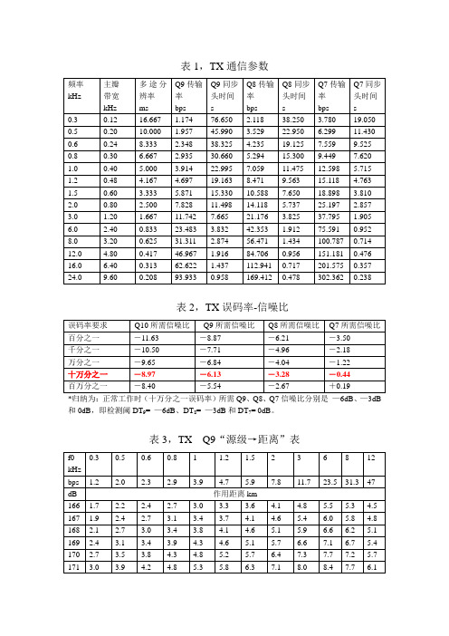
0.48
4.167
4.697
19.163
8.471
9.563
15.118
4.763
1.5
0.60
3.333
5.871
15.330
10.588
7.650
18.898
3.810
2.0
0.80
2.500
7.828
11.498
14.118
5.737
25.197
2.857
3.0
1.20
1.667
11.742
154.9
144.2
132.4
118.1
96.5
54.2
38.9
22.9
211
235.2
215.7
202.3
179.6
163.2
151.4
138.4
123.0
100.0
55.7
39.9
23.4
212
257.3
231.5
215.7
189.9
171.8
158.7
144.6
128.0
103.6
57.3
40.9
7.665
21.176
3.825
37.795
1.905
6.0
2.40
0.833
23.483
3.832
42.353
1.912
75.591
0.952
8.0
3.20
0.625
31.311
2.874
56.471
1.434
100.787
0.714
12.0
4.80
七星飞行
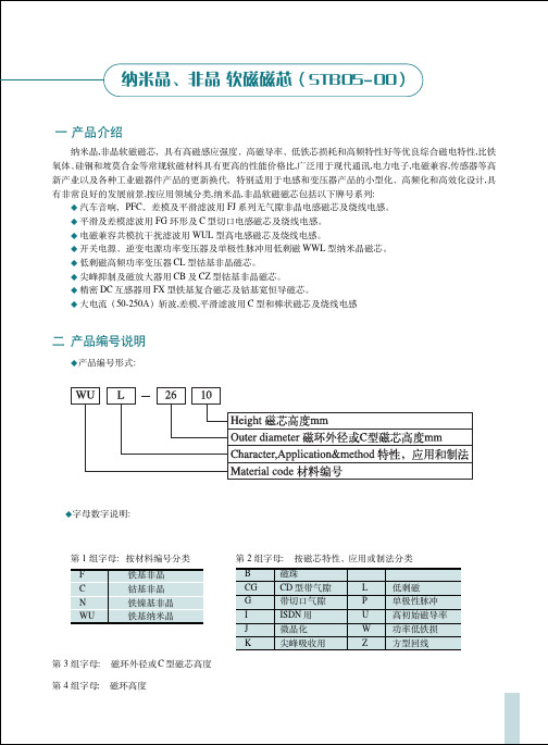
AMORPHOUS AND MICROCRYSTALLINE
! ! Ae (mm2) 7.0 8.4 19.2 24.5 35.0 42.0 65.7 133 166 Le (cm) 3.77 4.08 4.55 4.55 6.60 8.16 10.21 115 115 AL0 Idc=0 (µH/N2) 0.072 0.150 0.130 0.160 0.150 0.160 0.250 0.368 0.460 !"#$ DC bias rated (A.T) 111 121 136 136 192 244 302 344 344
STB05-01B
25Oe !" !"#$ !", 5) AL !"# 50%
!"#$%&', !"#$(300KHz) !"# PFC
! ! Ae (mm2) 5.5 16.8 19.2 24.5 35.0 Le (cm) 2.59 4.08 4.55 4.55 6.60 AL0 Idc=0 (µH/N2) 0.072 0.141 0.147 0.184 0.200 DC bias rated (A.T) 50.8 78.0 87.0 87.0 127.0
6.5 10.3 10.3 10.2 12.2 12.2 12.2 10 12
AL Idc=0 (µH/N2) 0.19 0.85 0.50 0.70 0.50 0.57 0.78 0.30 0.84
DCB rated (A.T) 38 16 20 24 20 46 30 54 31.5
!"# bias properties N Idc Lv rated min (T) (A) (µH) 38 1.0 100 32 0.5 500 20 1.0 150 24 1.0 250 20 1.0 150 27 1.7 240 30 1.0 350 27 2.0 187 28 1.8 280
电线电缆材料消耗计算标准
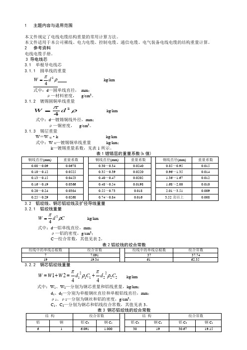
1 主题内容与适用范围本文件规定了电线电缆结构重量的常用计算方法。
本文件适用于本公司裸线、电力电缆、控制电缆、通信电缆、电气装备电线电缆的结构重量计算。
2 参考资料 电线电缆手册。
3 导电线芯3.1 单根导电线芯 3.1.1 圆单线的重量ρπ24d W =kg/km式中:d —圆单线直径, mm ;ρ—材料密度, g/cm 3。
3.1.2 镀锡圆铜单线重量ρπ24d W =kg/km式中:d —镀锡铜线外径,mm ;ρ—铜密度, g/cm 3。
3.1.3 锡层重量W =W 铜·k kg/km 式中:W 铜—镀锡铜单线重量 kg/km ; k —镀锡重量系数,见表1所示。
3.2.1 铝绞线重量C d W ρπ24=kg/km式中:d —铝单线直径,mm ;ρ—铝的密度,g/cm 3;C —绞合常数,其值见表2。
222211214421C d C d W W W ρπρπ+=+= kg/km式中:W 1、W 2—分别为钢芯重量和铝线重量,kg/km ;d 1、d 2—分别为单根钢丝直径和单根铝线直径,mm ; ρ1、ρ2—分别为钢丝和铝的密度,g/cm 3;C 1、C 2—分别为钢芯和铝线绞合常数,其值见表3。
3.2.3.1 扩径钢芯铝绞线的重量 ()[]铝铝钢钢ρρπm n n m K d Z d Z d Z K d Z W 2222211204+++=kg/km式中:Z 0—钢线根数;d 0—钢丝直径,mm ;Z 1、Z 2…Z n —分别为第一层、第二层…最外层铝单线根数; d 1、d 2…d n —分别为第一层、第二层…最外层铝单线直径,mm ; k m 钢、k m 铝—分别为钢线部分及铝线部分的平均绞入系数。
ρ钢、ρ铝—分别为钢及铝的密度,g/cm 3。
3.2.3.2 空心扩径绞线的重量W=W 支+W 铝+W 钢 kg/km 式中:W 支—中心支撑物重量,kg/kmW 铝—铝线重量,铝铝铝铝铝ρπmq K Z d w 24= kg/km W 钢—钢线重量,钢钢钢钢钢ρπm K Z d w 24=kg/km3.3 普通绞线重量3.3.1 绞线的平均绞入系数 nnn m Z Z Z Z k Z k Z k Z k Z k ++++++++= (210221100)式中:Z 0、Z 1、Z 2 …Z n —分别为中心层及其它各层的单线根数;k 0、k 1、k 2 …k n —分别为中心层及其它各层的绞入系数。
机械设备中英文对照表

dHiorericztoionntaall ddirriellctional drill Trencher Ditcher
GBS HBR505D 60系列 凯斯
威猛 GC18(12)
威猛
CASE
备注
工程机械设备中英文对照表
机械名称
生产厂家
序号
中文
6.2 水泥罐车
6.3 载重汽车
6.4 拖车
英文
cement tank truck autotruck trailer
型号
中文译名
英文
6.5 6.6
7 桥梁施工机械
7.1 架桥机 7.2 运梁车
DF450 DCY450
7.3
7.4
8 地铁施工机械
8.1 8.2 地下连续墙挖掘机 8.3 地下连续墙液压挖掘机 8.4 地下自卸车
意马
法国地基处理 公司
备注
5 起重机械, Lifting and hoisting equipment
5.1 门座式起重机
Gantry crane
MQ4026
5.2 塔式起重机
Tower crane
5.3 高架门座式起重机 High-level gantry crane
5.4 摆塔式缆索起重机 Luffing cable crane
3.7
石打石立轴冲击式破碎机 shaft impact crusher
美卓
碾压混凝土连续搅拌设 Uninterrupted mixing
备 3.8
unit for roller compacted concrete(RCC)
现代空袭兵器

现代空袭兵器【学习目标】1.了解什么是防空识别区2.理解为什么要学习现代防空3.了解中美两国主要空袭兵器【重点难点】理解为什么要学习现代防空【自学导航】带着以下问题阅读新知要点,并将自已的疑惑和收获写下来。
如果感觉新知要点的知识量不够,还可以在网络上寻找相应资料进行补充阅读。
1.什么是防空识别区?2.防空识别区的作用?3.现代战争的发展趋势?4.学习现代空袭兵器意义?5.中美有那些空袭战机?【新知要点】同学们,你们看了93阅兵吗?非常的壮观!给我们留下了难忘的映象,惊雷滚滚,气势如虹,创下了空中阅兵最大规模,我国最新型预警机500,新一代中远程轰炸机轰6k,第三代战斗机歼11.、第一代多用途舰载战斗机歼15均为列装后首次参阅。
我们一起再来看一看各型战机霸气亮相北京上空。
这次阅兵展示我国的军威,同时也展示了我国在空中的实力。
那么同学们知道哪些防空知识呢?我们首先来了解什么是1.防空识别区请同学们看大屏幕!1.防空识别区防空识别区,指的是一国基于空防、需要所划定的空域。
目的在于为军方及早发现、识别和实施空军拦截行动提供条件。
二战后,随着空中作战力量的发展,特别是以高空高速为基本特征的二代战斗机的发展,各国传统的防空体系面临较大威胁。
如果还按照对方目标逼近本国领空才出动战机拦截,时间不充裕,根本无法保证成功拦截。
于是在本国领空之外的公共空域(简称公空)划定防空识别区,就成了扩大预警空间、保证拦截时间的通行做法。
2013年11月23日,中华人民共和国政府根据一九九七年三月十四日《中华人民共和国国防法》、一九九五年十月三十日《中华人民共和国民用航空法》和二〇〇一年七月二十七日《中华人民共和国飞行基本规则》,宣布划设东海防空识别区。
具体范围为以下六点连线与我领海线之间空域范围:北纬33度11分、东经121度47分,北纬33度11分、东经125度00分,北纬31度00分、东经128度20分,北纬25度38分、东经125度00分,北纬24度45分、东经123度00分,北纬26度44分、东经120度58分。
Maxwell
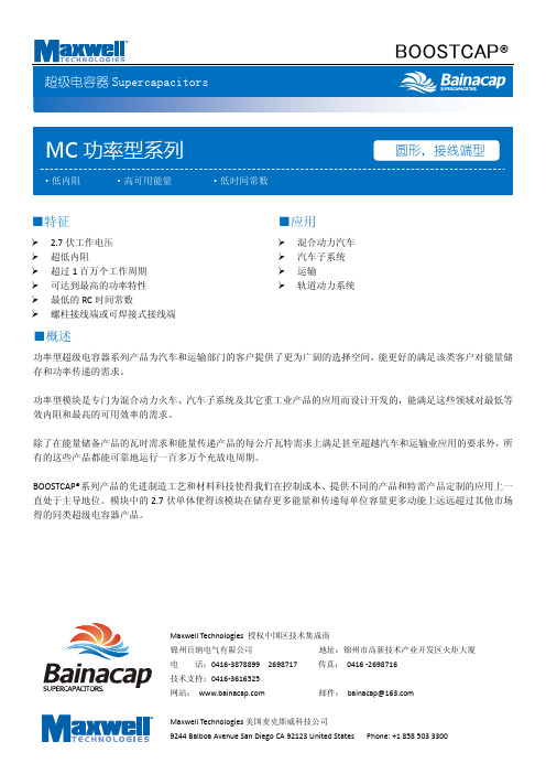
功率密度 (W/kg) 5,400 5,000 5,800 6,200 5,400
型号
BCAP0650 P270 T04 BCAP1200 P270 T04 BCAP1500 P270 T04 BCAP2000 P270 T04 BCAP3000 P270 T04
体积(L) 0.211 0.294 0.325 0.373 0.475
体积(L)
0.150 0.233 0.264 0.312 0.414
重量(kg)
0.20 0.30 0.32 0.40 0.55
L 51.5 ±0.5 74.0 ±0.3 85.0 ±0.3 102.0 ±0.3 138.0 ±0.3
尺寸 (mm)
H(±0.125)
D1(±0.2)
3.18
60.4
3.18
Ic=72小时后, 25˚c下的漏电电流 Rth =热阻
lsc =短路电流(最大峰值电流)
⁄ CV
V
M
RH
.V
R DC
地址:锦州市高新区雨露街 29 号 电话:0416‐3878899 2698717 传真:0416‐2698716
技术支持:0416‐3616525
Website:
电容(F) 650 1200 1500 2000 3000
等效内阻 DC (mΩ) 0.80 0.58 0.47 0.35 0.29
等效内阻 1khz(mΩ) 0.60 0.44 0.35 0.26 0.24
漏电电流(mA) 1.5 2.7 3.0 4.2 5.2
地址:锦州市高新区雨露街 29 号 电话:0416‐3878899 2698717 传真:0416‐2698716
锦州百纳电气有限公司
