GS25T24中文资料
基本称重仪表
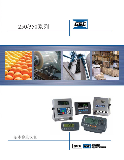
键盘
认证
250型
255型
350/355型和350锌压铸型
0.01到 99,950
30,000分度 ext. 分度, 最小0.25 μV/d
24位 A/D转换器 具有 8,388,608 内部的计数 可选择的 ±2% 到 ±20% F.S. 可选择的降低,放缓,加速 14 ˚F 到 122 ˚F (-10 ˚C 到 50 ˚C) 千克,磅 2年
当地经销商:
GSE中国大陆地区代理 希蒙电子国际有限公司 北京市海淀区温泉环山村 北京100095 中华人民共和国
电话:010-62450893/62481289 传真:010-62459016 marketing@
250/350系列
基本称250/350系列数字仪表来给予合理的解决方案。可编程的功能键,内置功能 和可扩展选件的特性使得这一系列更加全面且简单。软件简化了安装程序。安装需要一个子网访问协议。 功能是经过改进过的。 具备简单的完整性和我们的最高标准,250/350系列是满足基本的应用需求的智能称重系统。
0.1–3.0 mV/V 4 或 6根 屏蔽导线
12–24 VDC 标准电源适配器 7.4 VDC (16) 350 Ohm
0.1–3.0 mV/V 4 或 6根 屏蔽导线
可选择 0.01 到 999,990 20 位A/D 转换器100,000显示 分度, 1,000,000内码
60 Hz
可选择的 0.01%到100% F.S. 可选择降低到20分度 14 ˚F 到 122 ˚F (-10 ˚C 到 50 ˚C) 千克,磅,克,磅-盎司,盎司 2年
350 系列
350型和355不锈钢型仪表可以被设置作为用于一台主仪表的远程显示或 可选附件
汽车诊断设备 J2534 产品说明书

目录1产品概述 (1)背景信息 (1)J2534 (1)车辆接口 (2)2产品介绍 (3)前面板 (3)顶面板 (4)底面板 (5)通电 (5)技术参数 (6)配件 (7)故障排查 (8)3驱动安装与网络配置 (9)驱动安装 (9)固件升级 (11)4使用J2534设备编程 (13)5合规信息 (15)6保修服务 (17)一年有效保修 (17)服务流程 (17)1产品概述背景信息目前市场上新一代车辆都配备大量车载电脑以完成不同特定任务,以致无需笔记本电脑即可进行汽车诊断和维修的时代即将过去。
常见的车载电脑包括发动机控制模块、变速箱控制模块、燃油喷射控制模块、防抱死制动系统、车身控制模块,以及其他众多控制模块。
用于管理从电动门锁到事故数据的每个电子控制系统。
每一个车载电脑都在工厂通过软件编程使其执行特定任务。
例如,发动机控制模块的软件中包含几百乃至几千个参数,用于控制火花,燃料,空转,巡航,排放量,油耗和驾驶性能。
同样,变速箱控制模块中也有用于控制变速器和变矩器工作的软件。
有时,在车辆运出之后,制造商仍会发布软件更新以改进排放量、油耗和驾驶性能,或用于修复原软件中引起特定保修问题的故障。
更新软件是一种积极主动的修复方式,因为可以在用户反馈或注意到问题之前将其解决。
这些模块中的软件更新通常被称为Flash编程。
对于新车代理商来说,Flash编程相对简单,因为他们的维修技术员与制造商有联系,配备昂贵的专业维修工具来进行编程。
对于独立的修理厂来说这是一个更大的挑战,因为大多数修理厂都会维修不止一种型号的车辆。
他们要操作几十个不同制造商的维修工具,这大大增加了其工作的复杂程度,成本和所需的操作培训。
J25342000年,美国环保局在监管汽车排放问题之后决定采取措施,要求美国汽车工程师学会制定一项相关排放标准,J2534由此应运而生。
J2534是一项强制性的规定,要求在美国销售车辆的汽车制造商都必须遵循。
为适用于所有车型,最初的J2534后又更新为J2534-1。
TEGAM 252 253 254 四参量检测仪说明书
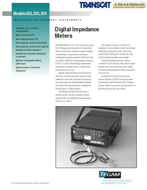
TEGAM Models 252, 253, and 254 are used for evaluating and inspecting components.These meters provide direct, digital display of inductance, capacitance, resistance,conductance and dissipation. They have the versatility and basic measurement accuracy,0.25%, to satisfy demanding engineering and inspection applications, while being extremely easy to use.Simply push the button for the desired function, set the range and connect to the unknown. True four-terminal connections are ensured by the standard Kelvin Klip®test leads. The measurement is displayed on the large 3.5 digit readout.The Model 253 has all of the above characteristics, an auto-ranging feature, and includes one additional measurement range for C and G.The Model 254 has a 120 Hz testfrequency, which makes it ideal for testing electrolytic capacitors. It has full scale ranges from 2,000 pF to 20,000 µF with 1 pF resolution on the lowest range.An optional battery power pack isavailable on all versions. This allows these meters to be used with line power when available and unplugged when convenient or necessary.Available accessories include the optional Model 1412B Universal Limits Comparator and the Model 2001 Sorting Fixture. Other accessories are presented on the back page of this data sheet.Digital ImpedanceMetersE N T I N S T R U M E N T STHE GLOBAL SOURCE FOR PROVEN TESTAND MEASUREMENT TECHNOLOGY.Prices and specifications subject to change without notice.Static Charge ProtectionDiode and resistor discharge network.Power Requirements100 to 125V or 200 to 250V , 50/60Hz, 4W.DimensionsHeight 10 cm (4 inches).Width 26 cm (10 inches).Depth 37 cm (14.6 inches).Weight3.2 kg (7 lbs) net.* Digit count, same range.** After correction for test lead zero reading 0°C to 15°C and 35°C to 50°C add 0.1 (rated accuracy) °C.Test Frequency1kHz (252 & 253); 120 Hz (254). Optional 100 Hz (254).Measurement Speed4 per second; one second required for first reading after connection to unknown.Connection to UnknownFour-terminal, guarded. Kelvin Klips ®supplied with unit.Display3.5 digits with decimal point; blanked for overload conditions.External Bias 0 to 50VDC.Analog OutputsL, C, R or G, with simultaneous output of D for L and C.Accuracy (15˚ C to 35˚ C)Test Signal252 RangesRange No.0123456L s 200µH 2mH 20mH 200mH 2H 20H 200H C p 200pF 2nF 20nF 200nF 2µF 20µF 200µF R s 2Ω20Ω200Ω2k Ω20k Ω200k Ω2000k ΩG p 2µS20µS200µS2mS20mS200mS2000mSD1.999253 RangesRange No.01234567L s 200µH 2mH 20mH 200mH 2H 20H 200H 200H C p 200pF 2nF 20nF 200nF 2µF 20µF 200µF 2000µF R s 2Ω20Ω200Ω2k Ω20k Ω200k Ω2000k Ω2000k ΩG p 2µS20µS200µS2mS20mS200mS2000mS20SD1.999254 RangesRange No.01234567L s 2000µH 20mH 200mH 2000mH 20H 200H 2000H 2000H C p 2nF 20nF 200nF 2µF 20µF 200µF 2000µF 20mF R s 2Ω20Ω200Ω2k Ω20k Ω200k Ω2000k Ω2000k ΩG p 2µS20µS200µS2000µS20mS200mS2000mS20SD1.999Standard EquipmentKelvin Klips ®43072 Instruction Manual for 25243158Instruction Manual for 25343761Instruction Manual for 25443762±(0.25% +(1 + 0.002R s *) counts)**L s±(0.25% + (1 + 0.001R s *) counts)±(0.25%+(1 + 0.002R s *) counts)±(0.25% +(1 + 0.002R s *) counts)±(0.25% +(1 + 0.002G p *) counts)**C p±(0.25% + (1 + 0.001G p *) counts)±(0.25% +(1 + 0.002G p *) counts)±(0.5% +(1 + 0.004G p *) counts)±(0.25% +(1 + 0.002L s *) counts)R s±(0.25% + (1 + 0.001L s *) counts)±(0.25% + (1 + 0.002L s *) counts)0.25% +(1 + 0.002L s *) counts)±(0.25% +(1 + 0.002C p *) counts)G p±(0.25% + (1 + 0.001C p *) counts)±(0.25% +(1 + 0.002C p *) counts)±(0.5% +(1 + 0.004C p *) counts)±(1% + 0.002) for L or C ≥200 counts; ±(2% + 0.010) for L or C 50 to 199 countsD Voltage C p ,G p 1.0VRMS 0.1VRMS 0.01VRMS Current L s ,R s100mA10mA1mA100µA10µA1µA±(2% + 0.10)SpecificationsLimit Controls -%% deviation lower limit +%% deviation upper limit D dissipation factor upper limitRangesNominal value 00500 to 19999 (corresponds to DPM reading of companion unit).-%-99.9% to 0, -9.99% to 0+%0 to 99.9%, 0 to 9.99%D 0 to 0.999, 0 to 0.0999AccuracyNominal Value ±0.1% of reading(01999 to 19999)±0.3% of reading (00500 to 01999)% limits ±0.5% of full scale D limit±0.5% of full scale Front Panel Lamp IndicationsGO indicates value between- and + % limits, and less than D limit.LO indicates value lessthan - limit HI indicates value greater than + limitD HIindicates factor greater than D limitRelay Contacts (Rear Panel Connections)Four pairs of isolated relay contacts(DPST) close individually in synchronism with front panel lamp indications.Relay Contacts Ratings3 watts dc, 28 volts dc maximum,100 milliamperes; 1 millisecond switch closure time.Gated Relay ClosureGated model operation may be selected by means of a rear panel switch. In this conditionLimits Comparator Relay outputs for Handler operation•Front panel LED for manual sorting •Resolution for nominal 4-1/2 digit •Independent upper and lower limits •Sort by C and D simultaneously •Sorts R,L and G•Operates with 252,253 or 254The Model 1412B is a Limits Comparator used to automatically or manually sort components. When used with a TEGAM Model 252, 253, or 254, it provides either a “GO”, “HI”, or “LOW” indication for R, L,C, or G. The Model 1412B simultaneously sorts for D and C, so there is also a “D HI”indication for this condition.Using the 1412B speeds sorting andminimizes component handling. One method of the acceptance indication is through a rear panel connector which allows for integration into a system by connecting the 1412B to automatic handling equipment.The other indication method is the front panel LED’s. There is also a gated mode,where a comparison is initiated by a control switch and held for an adjustable time, up to two seconds, after release of the switch.Both these features simplify manual use.Resolution of the nominal value is 4.5digits and the limits switches have three digit resolution. The system has two limits ranges,10% and 100% of full scale, allowing for range settings of 0 to 9.99% or 0 to 99.9%.The D limit also has two ranges. The upper and lower limits are set independently,which adds to the outstanding flexibility and accuracy of the system.the relay contacts remain open when a limit is reached, unless closure is initiated by a control switch. Duration of closure, after the control switch is released, is determined by the adjustment of a timing control (two seconds maximum).Input SignalsC, L, R, G analog; D analog; analog common.Internal reference voltage used with TEGAM Model 252, 253, 254 or other instruments,selected by rear panel switch.DimensionsHeight 13.5 cm (5.3 inches)Width 21.6 cm (8.5 inches)Depth (overall) 33 cm (13 inches)Weight3.63 kg (8 lbs) net.Standard EquipmentInterconnection Cable 42855 Instruction Manual for 1412B 42428Options and AccessoriesBattery Powered 252SP2596Battery Powered 253SP2598Battery Powered 254SP2599Dust Cover 43374Sorting Fixture 2001Cable Set for 200143586LINE VOLTAGE 10250/60 Mz100/120220/240FUSE SIZE 1/2A1/4A UNLATCHCalibration & Technical ServicesFor warranty and remedial repair, calibration services and spare parts, or for additional information on TEGAM sales and service offices around the world, contact us at 440-466-6100 (ph) or 440-466-6110 (fx).252.991PGTHE GLOBAL SOURCE FOR PROVEN TESTAND MEASUREMENT TECHNOLOGY.TEN TEGAM WAY • GENEVA,OHIO 44041440-466-6100 • FAX 440-466-6110 • e-mail:***************。
GS-2406T PLUS GS-3405T PLUS Series 热转式 热感式 SUR

GS-2406T PLUS / GS-3405T PLUS / Series热转式/热感式SURPASS PLUS条码印表机使用手册Ver.1.1.3Agency Compliance and ApprovalsEN 55032, Class AEN 55024This is a class A product. In a domestic environment this product may cause radiointerference in which case the user may be required to take adequate measures.FCC part 15B, Class AThis equipment has been tested and found to comply with the limits for a Class Adigital device, pursuant to Part 15 of the FCC Rules. These limits are designed toprovide reasonable protection against harmful interference when the equipment isoperated in a commercial environment. This equipment generates, uses, and canradiate radio frequency energy and, if not installed and used in accordance with themanufacturer’s instruction manual, may cause harmful interference with radiocommunications. Operation of this equipment in a residential area is likely to causeharmful interference, in which case you will be required to correct the interference atyour own expense.FCC 符合声明此设施符合第15 部份的规则。
1002 212 025说明书

Safety Information . . . . . . . . . . . . . . . . . . . . . . . . . . . . . . . . . . 2 Warranty . . . . . . . . . . . . . . . . . . . . . . . . . . . . . . . . . . . . . . . . . . 3 Pre-Installation . . . . . . . . . . . . . . . . . . . . . . . . . . . . . . . . . . . . . 3 Installation . . . . . . . . . . . . . . . . . . . . . . . . . . . . . . . . . . . . . . . . 6Before you begin, carefully read and understand the instructions in this manual. Please follow the instructions in the order presented inthis manual and observe all warnings and cautions.This mount has been tested to support a television with a minimum of 20 in. (51 cm) and a maximum 56 in. (142 cm)diagonal screen and a weight up to 80 lbs. (36 kgs).The manufacturer warrants that it will replace or repair this item, free of charge, at the manufacturer’s sole discretion, should it prove defective in materials or workmanship.This warranty does not apply to:□Normal wear and tear□Friction damage□Coating defects□Defects caused by loosened screws, nuts, or bolts□Improperly mounting the bracket to the wall□Improperly installing the bracket to the display□Failure to properly follow installation instructions□Modifi cation or repairs not made or authorized by the manufacturer□Loading beyond permitted load□Intentional misuseContact the Customer Service Team at 1-877-527-0313 or visit .PLANNING INSTALLATIONCompare all parts in the package with the Hardware Included and Package Contents lists in this manual. If any part is missing or damaged, do not install this wall mount system and call customer service at 1-877-527-0313 or visit .This wall mount bracket is compatible with VESA 100/200/300/400 mm mounting holes.PLANNING WALL PLACEMENTWhen selecting a wall to mount your display, keep the following in mind:□Select a place with easy access to power outlets, cable input sources, and connections for speakers and accessories.□Avoid direct sunlight, heat, and vibrations and do not place in direct fl ow of traffi c.□Select a weight-bearing wall. The wall must be able to safely support four times the combined load of the equipment and all attached hardware and components.PLANNING MOUNTING HEIGHTThe optimal viewing height is to center the display at eye level when seated. Many people consider this to be too low for a wall mount, and commonly use the following rule for placement:□Position the bottom of the display no higher than eye level when seated, and the top of the display no higher than eye level when standing. Anything within these limits should normally provide a comfortable viewing experience.ENSURING WALL STABILITYCarefully inspect the wall area you have selected. Examine the wall surface before you begin drilling.□For concrete walls, check for damaged or loose concrete and do not drill in those areas. □For brick wall, never drill into the mortar between blocks.□For wood studs, locate the wall studs and drill in the center of the stud.TOOLS REQUIRED (NOT INCLUDED IN THE PACKAGING)Power drill5-32 in. (4 mm) wood drill bit or 3/8 in. (10 mm) masonry drillbitsPhillipsscrewdriverStud finderMeasuringtapePencil HammerHARDWARE INCLUDEDAA BB CC DD EEJJFF GG HH IIPACKAGE CONTENTS7 Attaching the mounting arm to the□Align the mounting arm holes with the pre-drilled holes in the wall.□Use the level (C) to ensure that the mounting arm (A) is level on the wall.□Attach the mounting arm (A) to the wall using lag bolts(BB). Tighten the bolts (BB) securely using a Phillipsscrewdriver and a socket tool (not included).8Attaching the mounting plate to theTV (VESA 100 and 200)This procedure describes how to attach the mounting plate to VESA 100 and 200 TVs. For VESA 300 and 400, proceed to step 9. □If necessary, align spacers (EE) or (FF) over the mounting holes on the back of your TV. □Position the wall plate (A) over the TV and attach using the appropriately sized bolts (CC or DD) and washers(GG or HH).EE/FFAGG/HHDD AGG/HH100x100 / 200x200100x100 / 200x200CC9Attaching the mounting plate to the TV (VESA 300 and 400)□Attach the left and right arm extenders (B1 and B2) to the wall plate (A) using M6 x 8 bolts (II). □Align spacers (EE or FF) over the mounting holes on the back of your TV. □Position the wall plate (A) with extenders (B) over spacers (EE or FF) and attach them to the TV using the appropriate sized bolts (CC or DD) and washers (GG or HH).CC II JJB1B2B1B2GG/HHDD EE/FFGG/HH12 Adjusting the angle of the TV□Adjust the angle of the TV by loosening the handle (1) on the wall plate assembly (A). Refer to the fi gure for the various angle adjustments. Securely tighten the handle (1) when you are fi nished.Questions, problems, missing parts? Before returning to the store, call Commercial Electric Customer Service8 a.m. - 7 p.m., EST, Monday-Friday, 9 a.m. - 6 p.m., EST, Saturday1-877-527-0313Retain this manual for future use.。
FUJITSU PRIMERGY RX2530 M4 双处理器1U机架式服务器数据表说明书
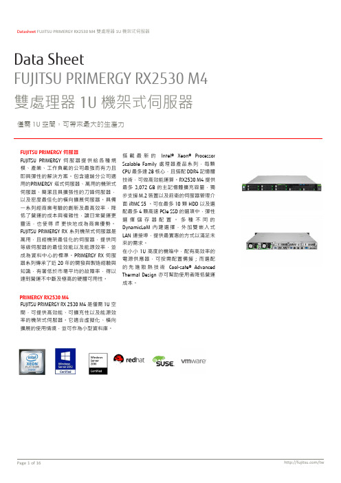
Datasheet FUJITSU PRIMERGY RX2530 M4 雙處理器1U 機架式伺服器Data SheetFUJITSU PRIMERGY RX2530 M4 雙處理器 1U 機架式伺服器僅需 1U 空間,可帶來最大的生產力特性與優勢技術規格PRIMERGY RX2530 M4機型PRIMERGY RX2530 M4LFF PRIMERGY RX2530 M4SFFPRIMERGY RX2530 M4SFFPRIMERGY RX2530 M4 SFF類型機架式機架式機架式機架式儲存磁碟架構4x 3.5 吋SAS/SATA4x 2.5 吋SAS/SATA8x 2.5 吋SAS/SATA10x2.5 吋SAS/SATA/PCIe/NVMe電源供應器熱插拔熱插拔熱插拔熱插拔產品型態雙處理器機架式伺服器雙處理器機架式伺服器雙處理器機架式伺服器雙處理器機架式伺服器主機板主機板型號D3383晶片組Intel® C624處理器數量與種類 1 - 2 x Intel® Xeon® Processor Scalable FamilyIntel® Xeon® Bronze Processor Intel® Xeon® Bronze 3104 (6C nHT, 1.70 GHz, TLC: 8.25 MB, Turbo: 1.70 GHz, 9.6 GT/s, Mem bus: 2,133MHz, 85 W, AVX Base 1.30 GHz, AVX Turbo 1.30 GHz)Intel® Xeon® Bronze 3106 (8C nHT, 1.70 GHz, TLC: 11 MB, Turbo: 1.70 GHz, 9.6 GT/s, Mem bus: 2,133MHz, 85 W, AVX Base 1.30 GHz, AVX Turbo 1.30 GHz)Intel® Xeon® Silver Processor Intel® Xeon® Silver 4108 (8C, 1.80 GHz, TLC: 11 MB, Turbo: 2.10 GHz, 9.6 GT/s, Mem bus: 2,400 MHz, 85W, AVX Base 1.30 GHz, AVX Turbo 1.30 GHz)Intel® Xeon® Silver 4110 (8C, 2.10 GHz, TLC: 11 MB, Turbo: 2.40 GHz, 9.6 GT/s, Mem bus: 2,400 MHz, 85W, AVX Base 1.70 GHz, AVX Turbo 2.10 GHz)Intel® Xeon® Silver 4112 (4C, 2.60 GHz, TLC: 8.25 MB, Turbo: 2.90 GHz, 9.6 GT/s, Mem bus: 2,400 MHz,85 W, AVX Base 2.20 GHz, AVX Turbo 2.60 GHz)Intel® Xeon® Silver 4114 (10C, 2.20 GHz, TLC: 13.75 MB, Turbo: 2.50 GHz, 9.6 GT/s, Mem bus: 2,400 MHz,85 W, AVX Base 1.80 GHz, AVX Turbo 2.20 GHz)Intel® Xeon® Silver 4114T (10C, 2.20 GHz, TLC: 13.75 MB, Turbo: 2.50 GHz, 9.6 GT/s, Mem bus: 2,400MHz, 85 W, AVX Base 1.80 GHz, AVX Turbo 2.20 GHz)Intel® Xeon® Silver 4116 (12C, 2.10 GHz, TLC: 16.5 MB, Turbo: 2.40 GHz, 9.6 GT/s, Mem bus: 2,400 MHz,85 W, AVX Base 1.70 GHz, AVX Turbo 2.10 GHz)Intel® Xeon® Gold Processor Intel® Xeon® Gold 5115 (10C, 2.40 GHz, TLC: 13.75 MB, Turbo: 2.80 GHz, 10.4 GT/s, Mem bus: 2,400MHz, 85 W, AVX Base 2.00 GHz, AVX Turbo 2.40 GHz)Intel® Xeon® Gold 5118 (12C, 2.30 GHz, TLC: 16.5 MB, Turbo: 2.70 GHz, 10.4 GT/s, Mem bus: 2,400 MHz,105 W, AVX Base 1.90 GHz, AVX Turbo 2.30 GHz)Intel® Xeon® Gold 5119T (14C, 1.90 GHz, TLC: 19.25 MB, Turbo: 2.30 GHz, 10.4 GT/s, Mem bus: 2,400MHz, 85 W, AVX Base 1.50 GHz, AVX Turbo 1.90 GHz)Intel® Xeon® Gold 5120 (14C, 2.20 GHz, TLC: 19.25 MB, Turbo: 2.60 GHz, 10.4 GT/s, Mem bus: 2,400MHz, 105 W, AVX Base 1.80 GHz, AVX Turbo 2.20 GHz)Intel® Xeon® Gold 5122 (4C, 3.60 GHz, TLC: 16.5 MB, Turbo: 3.70 GHz, 10.4 GT/s, Mem bus: 2,667 MHz,105 W, AVX Base 3.30 GHz, AVX Turbo 3.60 GHz)Intel® Xeon® Gold 6126 (12C, 2.60 GHz, TLC: 19.25 MB, Turbo: 3.30 GHz, 10.4 GT/s, Mem bus: 2,667MHz, 125 W, AVX Base 2.20 GHz, AVX Turbo 2.90 GHz)Intel® Xeon® Gold 6128 (6C, 3.40 GHz, TLC: 19.25 MB, Turbo: 3.70 GHz, 10.4 GT/s, Mem bus: 2,667 MHz,115 W, AVX Base 2.90 GHz, AVX Turbo 3.60 GHz)Intel® Xeon® Gold 6130 (16C, 2.10 GHz, TLC: 22 MB, Turbo: 2.80 GHz, 10.4 GT/s, Mem bus: 2,667 MHz,125 W, AVX Base 1.70 GHz, AVX Turbo 2.40 GHz)Intel® Xeon® Gold 6132 (14C, 2.60 GHz, TLC: 19.25 MB, Turbo: 3.30 GHz, 10.4 GT/s, Mem bus: 2,667MHz, 140 W, AVX Base 2.20 GHz, AVX Turbo 2.90 GHz)Intel® Xeon® Gold 6134 (8C, 3.20 GHz, TLC: 24.75 MB, Turbo: 3.70 GHz, 10.4 GT/s, Mem bus: 2,667 MHz,130 W, AVX Base 2.70 GHz, AVX Turbo 3.40 GHz)Intel® Xeon® Gold 6134M (8C, 3.20 GHz, TLC: 24.75 MB, Turbo: 3.70 GHz, 10.4 GT/s, Mem bus: 2,667MHz, 130 W, AVX Base 2.70 GHz, AVX Turbo 3.40 GHz)Intel® Xeon® Gold 6136 (12C, 3.00 GHz, TLC: 24.75 MB, Turbo: 3.30 GHz, 10.4 GT/s, Mem bus: 2,667MHz, 150 W, AVX Base 2.60 GHz, AVX Turbo 3.30 GHz)Intel® Xeon® Gold 6138 (20C, 2.00 GHz, TLC: 27.5 MB, Turbo: 2.70 GHz, 10.4 GT/s, Mem bus: 2,667 MHz,125 W, AVX Base 1.60 GHz, AVX Turbo 2.30 GHz)Intel® Xeon® Gold 6140 (18C, 2.30 GHz, TLC: 24.75 MB, Turbo: 3.00 GHz, 10.4 GT/s, Mem bus: 2,667MHz, 140 W, AVX Base 1.90 GHz, AVX Turbo 2.60 GHz)Intel® Xeon® Gold 6140M (18C, 2.30 GHz, TLC: 24.75 MB, Turbo: 3.00 GHz, 10.4 GT/s, Mem bus: 2,667MHz, 140 W, AVX Base 1.90 GHz, AVX Turbo 2.60 GHz)Intel® Xeon® Gold 6142 (16C, 2.60 GHz, TLC: 22 MB, Turbo: 3.30 GHz, 10.4 GT/s, Mem bus: 2,667 MHz,150 W, AVX Base 2.20 GHz, AVX Turbo 2.90 GHz)Intel® Xeon® Gold 6142M (16C, 2.60 GHz, TLC: 22 MB, Turbo: 3.30 GHz, 10.4 GT/s, Mem bus: 2,667 MHz,150 W, AVX Base 2.20 GHz, AVX Turbo 2.90 GHz)Intel® Xeon® Gold 6144 (8C, 3.50 GHz, TLC: 24.75 MB, Turbo: 4.10 GHz, 10.4 GT/s, Mem bus: 2,666 MHz,150 W, AVX Base 2.80 GHz, AVX Turbo 3.50 GHz)Intel® Xeon® Gold 6146 (12C, 3.20 GHz, TLC: 24.75 MB, Turbo: 3.90 GHz, 10.4 GT/s, Mem bus: 2,666MHz, 165 W, AVX Base 2.60 GHz, AVX Turbo 3.30 GHz)Intel® Xeon® Gold 6148 (20C, 2.40 GHz, TLC: 27.5 MB, Turbo: 3.10 GHz, 10.4 GT/s, Mem bus: 2,667 MHz,150 W, AVX Base 1.90 GHz, AVX Turbo 2.60 GHz)Intel® Xeon® Gold 6150 (18C, 2.70 GHz, TLC: 24.75 MB, Turbo: 3.40 GHz, 10.4 GT/s, Mem bus: 2,667MHz, 165 W, AVX Base 2.30 GHz, AVX Turbo 3.00 GHz)Intel® Xeon® Gold 6152 (22C, 2.10 GHz, TLC: 30.25 MB, Turbo: 2.80 GHz, 10.4 GT/s, Mem bus: 2,667MHz, 140 W, AVX Base 1.70 GHz, AVX Turbo 2.40 GHz)Intel® Xeon® Gold 6154 (18C, 3.00 GHz, TLC: 24.75 MB, Turbo: 3.70 GHz, 10.4 GT/s, Mem bus: 2,667MHz, 200 W, AVX Base 2.60 GHz, AVX Turbo 3.30 GHz)Intel® Xeon® Platinum Processor Intel® Xeon® Platinum 8153 (16C, 2.00 GHz, TLC: 22 MB, Turbo: 2.30 GHz, 10.4 GT/s, Mem bus: 2,667MHz, 125 W, AVX Base 1.60 GHz, AVX Turbo 2.00 GHz)Intel® Xeon® Platinum 8160 (24C, 2.10 GHz, TLC: 33 MB, Turbo: 2.80 GHz, 10.4 GT/s, Mem bus: 2,667MHz, 150 W, AVX Base 1.80 GHz, AVX Turbo 2.50 GHz)Intel® Xeon® Platinum 8160M (24C, 2.10 GHz, TLC: 33 MB, Turbo: 2.80 GHz, 10.4 GT/s, Mem bus: 2,667MHz, 150 W, AVX Base 1.80 GHz, AVX Turbo 2.50 GHz)Intel® Xeon® Platinum 8164 (26C, 2.00 GHz, TLC: 35.75 MB, Turbo: 2.70 GHz, 10.4 GT/s, Mem bus: 2,667MHz, 150 W,AVX Base 1.60 GHz, AVX Turbo 2.30 GHz)Intel® Xeon® Platinum 8168 (24C, 2.70 GHz, TLC: 33 MB, Turbo: 3.40 GHz, 10.4 GT/s, Mem bus: 2,667MHz, 205 W,AVX Base 2.30 GHz, AVX Turbo 3.00 GHz)Intel® Xeon® Platinum 8170 (26C, 2.10 GHz, TLC: 35.75 MB, Turbo: 2.80 GHz, 10.4 GT/s, Mem bus: 2,667MHz, 165 W,AVX Base 1.70 GHz, AVX Turbo 2.40 GHz)Intel® Xeon® Platinum 8170M (26C, 2.10 GHz, TLC: 35.75 MB, Turbo: 2.80 GHz, 10.4 GT/s, Mem bus:2,667 MHz, 165W, AVX Base 1.70 GHz, AVX Turbo 2.40 GHzIntel® Xeon® Platinum 8176 (28C, 2.10 GHz, TLC: 38.5 MB, Turbo: 2.80 GHz, 10.4 GT/s, Mem bus: 2,667MHz, 165 W,AVX Base 1.70 GHz, AVX Turbo 2.40 GHz)Intel® Xeon® Platinum 8176M (28C, 2.10 GHz, TLC: 38.5 MB, Turbo: 2.80 GHz, 10.4 GT/s, Mem bus:2,667 MHz, 165W, AVX Base 1.70 GHz, AVX Turbo 2.40 GHz)Intel® Xeon® Platinum 8180 (28C, 2.50 GHz, TLC: 38.5 MB, Turbo: 3.20 GHz, 10.4 GT/s, Mem bus: 2,667MHz, 205 W,AVX Base 1.70 GHz, AVX Turbo 2.30 GHz)Intel® Xeon® Platinum 8180M (28C, 2.50 GHz, TLC: 38.5 MB, Turbo: 3.20 GHz, 10.4 GT/s, Mem bus:2,667 MHz, 205W, AVX Base 1.70 GHz, AVX Turbo 2.30 GH記憶體插槽24 (每顆 CPU 6 個通道,每通道 2 個插槽,共 12 個 DIMM)記憶體插槽類型DIMM (DDR4)記憶體容量(最小-最大) 8 GB - 3072 GB記憶體保護高級ECC記憶體擦除SDDC支援Rank sparing memory支援Memory Mirroring記憶體說明Memory Mirroring 需在兩通道中的記憶體庫中有相同的一對記憶體模組(每記憶體庫有 6 個模組),Rank sparing 或 Performance Mode 需在六個通道中有相同的記憶體模組記憶體選項8 GB (1 module(s) 8 GB) DDR4, registered, ECC, 2,666 MHz, PC4-2666, DIMM, 1Rx48 GB (1 module(s) 8 GB) DDR4, registered, ECC, 2,666 MHz, PC4-2666, DIMM, 1Rx88 GB (1 module(s) 8 GB) DDR4, registered, ECC, 2,666 MHz, PC4-2666, DIMM, 2Rx816 GB (1 module(s) 16 GB) DDR4, registered, ECC, 2,666 MHz, PC4-2666, DIMM, 1Rx416 GB (1 module(s) 16 GB) DDR4, registered, ECC, 2,666 MHz, PC4-2666, DIMM, 2Rx416 GB (1 module(s) 16 GB) DDR4, registered, ECC, 2,666 MHz, PC4-2666, DIMM, 2Rx832 GB (1 module(s) 32 GB) DDR4, registered, ECC, 2,666 MHz, PC4-2666, DIMM, 2Rx464 GB (1 module(s) 64 GB) DDR4 3DS, registered, ECC, 2,666 MHz, PC4-2666, DIMM, 4Rx464 GB (1 module(s) 64 GB) DDR4, registered, ECC, 2,666 MHz, PC4-2666, LRDIMM, 4Rx4128 GB (1 module(s) 128 GB) DDR4 3DS, registered, ECC, 2,666 MHz, PC4-2666, DIMM, 8Rx4介面USB 3.0 埠5x USB 3.0 埠 (2x 前方, 2x 後方, 1x 內部)10x2.5 吋機型只有 1x USB2.0 位於前方顯卡(15 針) 2 x VGA (其中一個選配於前方,不支援基座為10x2.5 吋機型)串列1(9 針) 1 選配 (將佔用 PCIe slot)管理LAN(RJ45) 1 x iRMC S5 專用管理 LAN 埠 (10/100/1000 Mbit/s)管理埠流量可切換至共用的內建 LAN 控制器連接埠, 速度及連接介面與前述介面卡有關內建或整合控制器RAID 控制器硬體儲存控制器選項請參考「組件」中說明SATA 控制器Intel® C624, 1 x SATA ODD 用 SATA 通道內建或整合控制器LAN 控制器Intel® C6242 x 1 Gbit/s onboard可選配DynamicLoM OCP adaptors:4 x 1 Gbit/s Ethernet (RJ45)2 x 10 Gbit/s Ethernet (RJ45)2 x 10 Gbit/s SFP+4 x 10 Gbit/s SFP+所有支援特性已於相關系統配置中描述Wake-on-LAN supported on onboard Port 1 and 2.PXE-Boot via LAN from PXE server, iSCSI / FCoE boot (also diskless).額外的 LAN controller(PCIe Cards) 如下表所列。
固纬电子任意波形信号发生器的技术参数和特点说明书

超越传统、创新价值的任意波形信号发生器固纬电子最新推出一款轻巧紧凑的兼具直流电源的任意波信号源模块AFG-22SP。
其与GDS-2000A系列示波器可无缝对接,并可完美嵌入GDS-2000A示波器底座下,使示波器、信号源以及电源三者结合极大节约了实验桌的空间。
AFG-22SP等性能的双通道都具有2SMHz频率带宽(正弦波/方波),l u H z分辨率,内置正强波、方波、脉冲波、三角波以及噪声波。
对于任意波功能,2个通道都提供l20MSa/s采样率,10位分辨率,4k点记录长度,同时内置66种任意波供用户选择。
另外AFG-22SP还提供AM/FM/PM/FSK/SUM/Bust调制,扫频等功能,用于各种通信领域应用。
AFG-22SP的两个通道可以进行独立或关联配置。
提供藕合,跟踪,相位三种运算功能。
另外还提供2.SV/3.3V /SV, 0.6A的直流电源输出,提供简单的供电需求,给用户提供便利。
为了满足不同害户的需求,AFG-125/225系列信号源模块另有单通道以及不带电源输出的机种供选择。
「�l AFC-225P 2SMHz带宽,双通道,任意波形信号发生器(含直流电源输出)AFC-125P 2SMHz带宽,单通道,任意波形信号发生器(含直流电源输出)’, ... ..,>, r仿仰,\mor.�'\ \',�·.r.ttnn ;�rlll'111t.r 「i1「1@1.「�1、叭’”’…r.to.r> ·n11v W制巾,向J T、,「画1「�l.τ 言M{:......... . .......AFC-225 25 M Hz带宽,双通道,任意波形信号发生器AFC-125 2SMH z带宽,单通道,任意波形信号发生器|田等能逼迫信号输AFG-22S/22SP特有的等性能双通道信号输出功能,如同将两台性能相同的单通道任意波函数信号发生器一起使用,而不是分为主通道与附属通道,其中附属通道仅提供较少数的功能或规格较差。
GS25T48资料
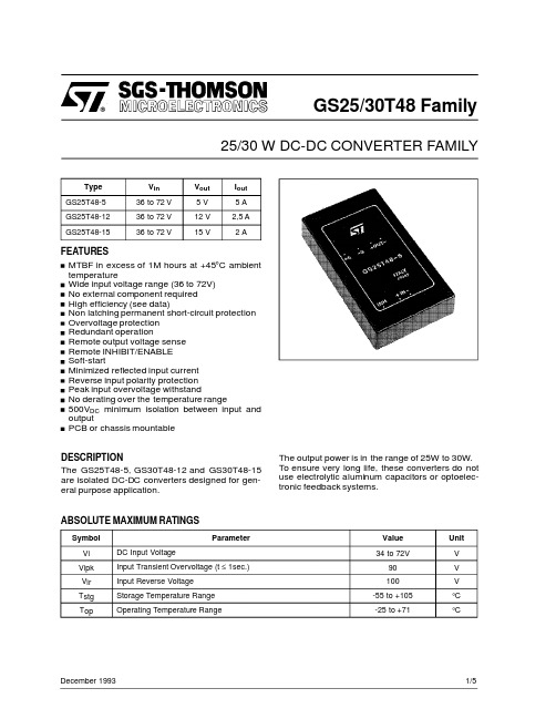
GS25/30T48Family25/30W DC-DC CONVERTER FAMILYDecember 19931/5Type V in V out I out GS25T48-536to 72V 5V 5A GS25T48-1236to 72V 12V 2,5A GS25T48-1536to 72V15V2AFEATURESMTBF in excess of 1M hours at +45°C ambient temperatureWide input voltage range (36to 72V)No external component required High efficiency (see data)Non latching permanent short-circuit protection Overvoltage protection Redundant operationRemote output voltage sense Remote INHIBIT/ENABLE Soft-startMinimized reflected input current Reverse input polarity protection Peak input overvoltage withstandNo derating over the temperature range500V DC minimum isolation between input and outputPCB or chassis mountableDESCRIPTIONThe GS25T48-5,GS30T48-12and GS30T48-15are isolated DC-DC converters designed for gen-eral purpose application.The output power is in the range of 25W to 30W.To ensure very long life,these converters do not use electrolytic aluminum capacitors or optoelec-tronic feedback systems.ABSOLUTE MAXIMUM RATINGSSymbol ParameterValue Unit V i DC Input Voltage34to 72VV V ipk Input Transient Overvoltage (t ≤1sec.)90V V ir Input Reverse Voltage 100V T stg Storage Temperature Range -55to +105°C T opOperating Temperature Range-25to +71°CELECTRICAL CHARACTERISTICS(T amb=25°C unless otherwise specified)Symbol Parameter Test Conditions Min Typ Max Unit V i Input Voltage Full Load364872VI i Input Current GS25T48-5Full Load640mAGS30T48-12Full Load730GS30T48-15Full Load730I ir Input ReflectedCurrent V i=48V Full Load50mAppI isc Input Short-circuitCurrent GS25T48-5V i=48V710mA GS30T48-12V i=48V820GS30T48-15V i=48V820l iq Input QuiescentCurrent V i=48VConverter OFF5mAV inhl Low Inhibit Voltage V i=48V Full Load 1.2VV inhh High Inhibit Voltage V i=48V Full Load 1.8(open)V l inh Input Inhibit Current Vi=48V Full Load1mAV o Output Voltage GS25T48-5V i=48V Full Load4.955.00 5.05VGS30T48-12V i=48V Full Load11.8812.0012.12GS30T48-15V i=48V Full Load14.8515.0015.15V or Output Ripple andNoise Voltage V i=48VFull Load10mVppδV o Line Regulation V i=36to72VFull Load±0.001%δV o Load Regulation V i=48VFull Load to No Load±0.05%V oov Output OvervoltageProtection GS25T48-5V i=48V Full Load 6.8V GS30T48-12V i=48V Full Load15GS30T48-15V i=48V Full Load18δVo Remote Sense per Leg V i=36V0.5VTc TemperatureCoefficient V i=48V Full LoadOperating Temperature Range+0.02%/°CGS25/30T48FAMILY2/5Symbol Parameter Test Conditions Min Typ Max UnitI o Output Current GS25T48-5V i=36to72V05A GS30T48-12V i=36to72V0 2.5GS30T48-15V i=36to72V02I osck Output Current Limit GS25T48-5V i=48V Overload5.5AGS30T48-12V i=48V Overload2.75GS30T48-15V i=48V Overload2.2t ss Soft-start Time V i=48V Full Load30mst rt Transient RecoveryTime V i=48VStep Load ChangeδIo=25%75µsV is Isolation Voltage500Vdc R is Isolation Resistance109Ωf s Switching Frequency150kHzηEfficiency GS25T48-5V i=48V Full Load81%GS30T48-12V i=48V Full Load86GS30T48-15V i=48V Full Load86R thc Thermal ResistanceCase to Ambient4°C/W ELECTRICAL CHARACTERISTICS(T amb=25°C unless otherwise specified)(cont’d)3/5GS25/30T48FAMILYPackage F.Dimensions in mm.(inches)CONNECTION DIAGRAM AND MECHANICAL DATA4/5PIN DESCRIPTIONPin FunctionDescription1-IN Negative input voltage.2+INPositive input voltage.Unregulated input voltage (typically 48V)must be applied between pins 1-2.The input section of the DC-DC converter is protected against reverse polarity by a series diode.No external fuse is required.Input is filtered by a Pi network.3ON/OFFLogically compatible with CMOS or open collector TTL.The converter is ON (Enable)when the voltage applied to this pin with reference to pin 1is higher than 1.8V.The converter is OFF (Inhibit)for a control voltage lower than 1.2V.When the pin is unconnected the converter is ON (Enable).4+SENSE Senses the remote load high side.To be connected to pin 6when remote sense is not used.5-SENSE Senses the remote load return.To be connected to pin 7when remote sense is not used.6+OUT Output voltage.7-OUTOutput voltage return.GS25/30T48FAMILYGS25/30T48FAMILYInformation furnished is believed to be accurate and reliable.However,SGS-THOMSON Microelectronics assumes no responsibility for the consequen ces of use of such information nor for any infringement of patents or other rights of third parties which may result from its use.No license is granted by implication or otherwise under any patent or patent rights of SGS-THOMSON Microelectronics.Specification mentioned in this publication are subject to change without notice.This publication supersedes and replaces all information previously supplied. SGS-THOMSON Microelectronics products are not authorized for use as critical components in life support devices or systems without express written approval of SGS-THOMSON Microelectronics.©1994SGS-THOMSON Microelectronics–All Rights ReservedSGS-THOMSON Microelectronics GROUP OF COMPANIESAustralia-Brazil-France-Germany-Hong Kong-Italy-Japan-Korea-Malaysia-Malta-Morocco-The Netherlands-Singapor e-Spain-Sweden-Switzerland-Taiwan-Thailand-United Kingdom-U.S.A.5/5。
GSS4224中文资料
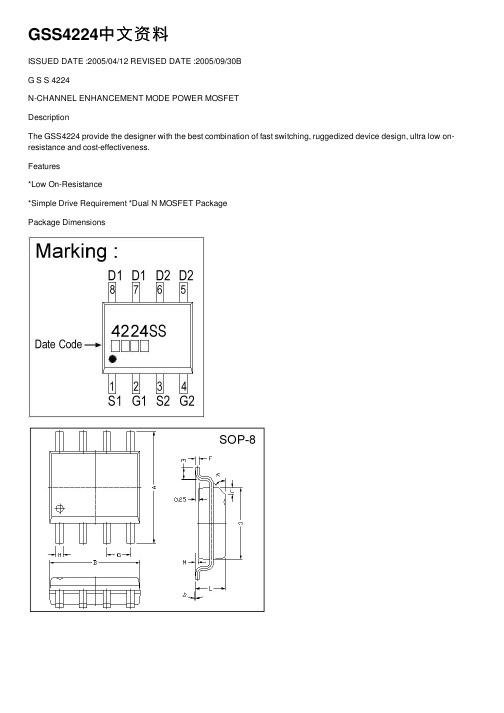
GSS4224中⽂资料ISSUED DATE :2005/04/12 REVISED DATE :2005/09/30BG S S 4224N-CHANNEL ENHANCEMENT MODE POWER MOSFETDescriptionThe GSS4224 provide the designer with the best combination of fast switching, ruggedized device design, ultra low on-resistance and cost-effectiveness.Features*Low On-Resistance*Simple Drive Requirement *Dual N MOSFET PackagePackage DimensionsMillimeter Millimeter REF . Min. Max.REF . Min. Max.A 5.80 6.20 M 0.10 0.25B 4.80 5.00 H 0.35 0.49C 3.80 4.00 L 1.35 1.75D 0 8 J 0.375 REF.E 0.40 0.90 K 45 F0.190.25G1.27 TYP .Absolute Maximum RatingsParameterSymbol Ratings Unit Drain-Source Voltage V DS 30 V Gate-Source Voltage V GS 20 V Continuous Drain Current 3 I D @TA =25 10 A Continuous Drain Current 3 I D @T A =708 A Pulsed Drain Current 1I DM 30 A Total Power Dissipation P D @T A =252 W Linear Derating Factor0.016 W/ Operating Junction and Storage Temperature RangeTj, Tstg-55 ~ +150Thermal DataParameterSymbol Value Unit Thermal Resistance Junction-ambient 3 Max.Rthj-amb62.5/WBV DSS 30V R DS(ON) 14m I D 10APb Free Plating ProductElectrical Characteristics(Tj = 25 Unless otherwise specified)ParameterSymbol Min. Typ. Max. Unit Test Conditions Drain-Source Breakdown VoltageBV DSS30 - - VV GS =0, I D =250uABreakdown Voltage Temperature CoefficientBV DSS /Tj- 0.03 - V/ Reference to 25 , I D =1mA Gate Threshold Voltage V GS(th) 1.0 - 3.0 V V DS =V GS , I D =250uA Forward Transconductance g fs - 16 - S V DS =10V, I D =10A Gate-Source Leakage CurrentI GSS - - 100 nA V GS = 20V Drain-Source Leakage Current(Tj=25 ) - - 1 uA V DS =30V, V GS =0 Drain-Source Leakage Current(Tj=70 )I DSS- - 25 uA V DS =24V, V GS =0 - - 14 V GS =10V, I D =10A Static Drain-Source On-Resistance 2R DS(ON) - - 20 mV GS =4.5V, I D =7A Total Gate Charge 2 Q g - 23 15 Gate-Source Charge Q gs - 6 - Gate-Drain (“Miller”) Change Q gd - 14 -nCI D =10A V DS =24V V GS =4.5V Turn-on Delay Time 2 T d(on) - 12 - Rise TimeT r - 8 - Turn-off Delay Time T d(off) - 34 - Fall Time T f - 16 - nsV DS =15V I D =1A V GS =10V R G =3.3 R D =15 Input Capacitance C iss - 1910 3070 Output CapacitanceC oss - 400 - Reverse Transfer Capacitance C rss - 280 - pFV GS =0V V DS =25V f=1.0MHz Gate ResistanceR g-0.9-f=1.0MHzSource-Drain DiodeParameterSymbol Min. Typ. Max. Unit Test Conditions Forward On Voltage 2V SD - - 1.2 V I S =1.7A, V GS =0V, Tj=25Reverse Recovery Time 2 T rr - 30 - nsReverse Recovery ChargeQ rr-24-nC I S =10A, V GS =0V dI/dt=100A/ sNotes: 1. Pulse width limited by Max. junction temperature. 2. Pulse width 300us, duty cycle 2% .3. Surface mounted on 1 in 2 copper pad of FR4 board; 135/W when mounted on Min. copper pad. Characteristics CurveFig 1. Typical Output Characteristics Fig 2. Typical Output Characteristics Fig 3. On-Resistance v.s. Gate VoltageFig 4. Normalized On-Resistancev.s. Junction TemperatureFig 6. Gate Threshold Voltage v.s.Junction TemperatureFig 5. Forward Characteristics of Reverse DiodeImportant Notice:All rights are reserved. Reproduction in whole or in part is prohibited without the prior written approval of GTM. GTM reserves the right to make changes to its products without notice. GTM semiconductor products are not warranted to be suitable for use in life-support Applications, or systems. GTM assumes no liability for any consequence of customer product design, infringement of patents, or application assistance. Head Office And Factory: Taiwan : No. 17-1 T atung Rd. Fu Kou Hsin-Chu Industrial Park, Hsin-Chu, T aiwan, R. O. C. TEL : 886-3-597-7061 FAX : 886-3-597-9220, 597-0785 China : (201203) No.255, Jang-Jiang T sai-Lueng RD. , Pu-Dung-Hsin District, Shang-Hai City, China TEL : 86-21-5895-7671 ~ 4 FAX : 86-21-38950165Fig 7. Gate Charge Characteristics Fig 8. Typical Capacitance CharacteristicsFig 9. Maximum Safe Operating Area Fig 10. Effective Transient Thermal ImpedanceFig 11. Switching Time WaveformFig 12. Gate Charge Waveform。
SG2524中文资料
PIN CONNECTION (Top view)
Value 40 100 50 –5
1000 – 65 to 150 – 25 to 85
0 to 70
Unit V mA mA mA
mW °C °C °C
THERMAL DATA
Symbol
Rth j-amb Rth j-alumina
CMV Common Mode Voltage
OUTPUT SECTION(each output)
Collector-emitter Voltage
Collector Leackage Curr.
Saturation Voltage
Emitter Output Voltage
tr tf Iq (*)
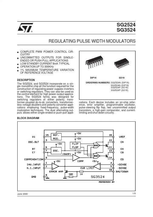
BLOCK DIAGRAM
DIP16
SO16
ORDERING NUMBERS: SG2524N (DIP16) SG3524N (DIP16) SG2524P (SO16) SG3524P (SO16)
cations. Each device includes an on-ship reference, error amplifier, programmable oscillator, pulse-steering flip flop, two uncommitted output transistors, a high-gain comparator, and currentlimiting and shut-down circuitry.
元器件交易网
SG2524
®
SG3524
REGULATING PULSE WIDTH MODULATORS
Agilent U1240系列手持数字多功能表数据表说明书
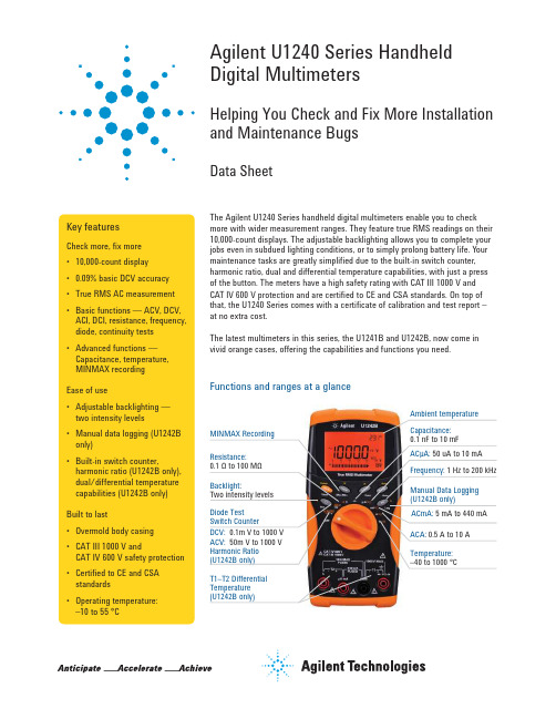
Agilent U1240 Series Handheld Digital MultimetersHelping You Check and Fix More Installation and Maintenance BugsData SheetThe Agilent U1240 Series handheld digital multimeters enable you to check more with wider measurement ranges. They feature true RMS readings on their 10,000-count displays. The adjustable backlighting allows you to complete your jobs even in subdued lighting conditions, or to simply prolong battery life. Your maintenance tasks are greatly simplified due to the built-in switch counter, harmonic ratio, dual and differential temperature capabilities, with just a press of the button. The meters have a high safety rating with CAT III 1000 V and CAT IV 600 V protection and are certified to CE and CSA standards. On top of that, the U1240 Series comes with a certificate of calibration and test report – at no extra cost.The latest multimeters in this series, the U1241B and U1242B, now come in vivid orange cases, offering the capabilities and functions you need.Key featuresCheck more, fix more • 10,000-count display • 0.09% basic DCV accuracy • True RMS AC measurement • Basic functions — ACV, DCV, ACI, DCI, resistance, frequency, diode, continuity tests • Advanced functions — Capacitance, temperature, MINMAX recording Ease of use• Adjustable backlighting — two intensity levels • Manual data logging (U1242B only)• Built-in switch counter,harmonic ratio (U1242B only), dual/differential temperature capabilities (U1242B only)Built to last• Overmold body casing • CAT III 1000 V andCAT IV 600 V safety protection • Certified to CE and CSA standards • Operating temperature:–10 to 55 °CAmbient temperatureT1–T2 Differential Temperature (U1242B only)Functions and ranges at a glanceDC specificationsVoltage11000.0 mV0.1 mV–0.09% + 510.000 V0.001 V–0.09% + 2 100.00 V0.01 V–1000.0 V0.1 V–0.15% + 5Current 1000.0 µA0.1 µA< 0.06 V (50 Ω)0.1% + 3 10000 µA 1 µA< 0.55 V (50 Ω)0.1% + 3 100.00 mA0.01 mA< 0.18 V (0.5 Ω)0.2% + 3 440.0 mA20.1 mA< 0.8 V (0.5 Ω)0.5% + 3 10.000 A30.001 A< 0.4 V (0.01 Ω)0.6% + 5Resistance41000.0 Ω50.1 Ω0.5 mA0.3% + 3 10.000 kΩ50.001 kΩ50 µA100.00 kΩ0.01 kΩ 4.91 µA1000.0 kΩ0.1 kΩ447 nA10.000 MΩ0.001 MΩ112 nA0.8% + 3 100.00 MΩ60.01 MΩ112 nA 1.5% + 3Diode test7 1 V0.001 V approximately 0.5 mA0.3% + 21. Input impedance: 10 MΩ (nominal).2. Current can be measured up to 440 mA continuously. An additional 0.2% needs to be added to the specified accuracy if the signal measured is in therange of 440 mA to 1100 mA for 30 seconds maximum. After measuring a current of > 440 mA, leave the meter to cool down for twice the measur-ing time used before applying a low current measurement.3. Current can be measured up to 10 A continuously with a maximum operating temperature of 50 °C. An additional 0.3% needs to be added to thespecified accuracy if the signal measured is in the range of 10 A to 19.999 A for 15 seconds maximum. After measuring a current of > 10 A, leave the meter to cool down for 60 seconds before applying a low current measurement.4. The maximum open voltage is < 2.8 V. For instant continuity, the built-in buzzer sounds when resistance is < 10.0 Ω.5. The accuracy of 1 kΩ and 10 kΩ is specified after Null function, which is used to substrate the test lead resistance and the thermal effect.6. For the range of 100 MΩ, the R.H. is specified for < 60%. The temperature coefficient will be 0.15 times of specified accuracy as > 50 MΩ.7. Overload protection: 1000 V RMS for circuits < 0.3 A short circuit current. The built-in buzzer sounds when reading is approximately below 50 mV andaudible single tone for normal forward biased diode or semiconductor junction as 0.3 V ≤ Reading ≤ 0.8 V.AC specificationsAC voltage8, 12 True RMS 1000.0 mV0.1 mV–1% + 52% + 5–10.000 V0.001 V–1% + 52% + 5 100.00 V0.01 V–1000.0 V0.1 V––AC current9, 12 True RMS 1000.0 µA0.1 µA< 0.06 V (50 Ω)1% + 5 1.5% + 5–10000 µA 1 µA< 0.55 V (50 Ω)100.00 mA0.01 mA< 0.18 V (0.5 Ω)440.0 mA100.1 mA< 0.8 V (0.5 Ω)10.000 A110.001 A< 0.4 V (0.01 Ω)8. Input impedance: 10 MΩ (nominal) in parallel with < 100 pF, with overload protection of 1000 V RMS9. Crest factor ≤ 3. For non-sinusoidal waveforms with crest factor up to 3, add 2% reading + 2% full scale typical.10. Current can be measured from 50 mA to 440 mA continuously. An additional 0.2% needs to be added to the specified accuracy if the signalmeasured is in the range of 440 mA to 1100 mA for 30 seconds maximum. After measuring a current of > 440 mA, leave the meter to cool down for twice the measuring time used before application of low current measurement.11. Current can be measured from 0.5 A up to 10 A continuously with a maximum operating temperature of 50 °C. An additional 0.3% needs to be addedto the specified accuracy if the signal measured is in the range of 10 A to 19.999 A for 15 seconds maximum. After measuring a current of >10 A, leave the meter to cool down for 60 seconds before applying a low current measurement.12. AC voltage and AC current specifications are AC coupled. True RMS measurement is valid from 5 % of range to 100 % of range. Temperature specificationsThermocouple type Range Resolution Accuracy ± (% of reading + offset error)K (for U1241B and U1242B)–40 to 1000 ºC/–48 to 1832 ºF0.1 °C /0.1 °F1% + 1 ºC/1% + 1.8 °FJ (for U1242B only)–40 to 1000 ºC/–48 to 1832 ºF0.1 ºC/0.1 ºF1% + 1 ºC/1% + 1.8 °FCapacitance specificationsRange Resolution Accuracy ± (% of reading + counts of least significant digit) 1000.0 nF0.1 nF1.2% + 410.000 µF0.001 µF100.00 µF0.01 µF1000.0 µF0.1 µF2% + 410.000 mF0.001 mFHarmonic ratio specificationsRange Frequency Voltage0.0% to 99.9%40 to 500 Hz100 mVAC to 1000 VACSwitch counter definition3Low level Normally close Lo< 370 ohms Intermittent 4Close to open Number of switch count Low to high transition High level Normally open Hi> 430 ohms Intermittent 5Open to closeNumber of switch countHigh to low transition1. Detects intermittent Opens or Closes lasting for at least 250 μsec.2. Test current of 0.5 mA with maximum open circuit voltage of 2.8 V is used.3. Maximum count reading: 199.99 M (display “OL” when achieving 2 x 10⁸ and thereafter).4. Count only low to high transition for initial switch condition of Low.5.Count only high to low transition for initial switch condition of High.Frequency specifications RangeResolutionAccuracy Minimum input frequency100.00 Hz 0.01 Hz 0.03%+3 1 Hz1000.0 Hz 0.1 Hz 10.000 kHz 0.001 kHz 100.00 kHz 0.01 kHz 1000.0 kHz 10.1 kHz1. Effective frequency measurement of up to 200 kHz; refer to frequency sensitivity table below for details.Frequency sensitivity during voltage measurement1000.0 mV 0.3 V 0.6 V 10.000 V 0.5 V 1.8 V100.00 V 5 V 10 V (< 100 kHz)1000.0 V50 V100 V (< 100 kHz)Frequency sensitivity during current measurement1000.0 µA 100 µA 10000 µA 500 µA 100.00 mA 10 mA 440.00 mA 50 mA 10.000 A1 AMeasuring rateACV7DCV (V or mV)7Ω14Diode14Capacitance 4 (< 100 µF)DCA (μA, mA, A)7ACA (μA, mA, A)7Temperature7 (single)Frequency 1 (> 10 Hz)General SpecificationsDisplay Dual display (secondary display is intended for temperature function display only)consists of 4-digit liquid crystal display (LCD) with maximum reading of 11,000 counts.Automatic polarity indication.Power consumption0.22 VA maximumBattery type and life Four single standard 1.5 V AAA batteries (Alkaline or Zinc Chloride type); 300 hourstypicalOperating environment• Full accuracy at –10 to 55 °C; and to 80% RH for temperatures up to 30 °C, decreasinglinearly to 50% RH at 55 °C• 0 – 2000 meters per IEC 61010-1 2nd Edition CAT III, 1000 V / CAT IV, 600 V IEC61010-1 2nd EditionStorage compliance–20 to 70 °CSafety compliance• IEC 61010-1:2001 / EN61010-1:2001• Canada: CSA C22.2 No. 61010-1:2004Measurement category CAT III 1000 V / CAT IV 600 V Overvoltage Protection, Pollution Degree 2EMC compliance• CISPR 11:1990/EN55011:1990• Canada: ICES-001:2004• Australia/New Zealand: AS/NZS CISPR11:2004Common Mode Rejection Ratio (CMRR)> 90 dB at DC, 50/60 Hz ± 0.1% (1 kΩ unbalanced)Normal Mode Rejection Ration (NMRR)> 60 dB at 50/60 Hz ± 0.1%Crest factor< 3.0Temperature coefficient0.1 × (specified accuracy) / °C (from –10 to 18 °C or 28 to 55 °C)Shock and vibration Tested to IEC/EN 60068-2Dimensions (H x W x D)193.8 mm x 92.2 mm x 58.0 mmWeight• 450 g with batteries• 400 g without batteriesWarranty• Three years for main unit• Three months for standard shipped accessoriesOrdering Information• Four 1.5 V AAA alkaline batteries• Certificate of Calibration (CoC)• Test probe leads (4-mm tips)• Quick Start Guide• Free test data (Option UK6)Measuring accessories (non-temperature)U1161A Extended testlead kit Includes two test leads (red and black), two test probes, medium-sized alligator clips and 4-mm banana plugs.• Test leads: CAT III 1000 V, CAT IV 600 V, 15 A• Test probes: CAT lll 1000 V, CAT lV 600 V, 15 A• Medium-sized alligator clips: CAT III 1000 V, CAT IV 600 V, 15 A • 4-mm banana plugs: CAT II 600 V, 10 AU1162AAlligator clips • One pair of insulated alligator clips (red and black).Recommended for use with Agilent standard test leads.• Rated CAT III 1000 V, CAT IV 600 V, 15 AU1163ASMT grabbers • One pair of SMT grabbers (red and black). Recommended for use with Agilent standard test leads.• Rated CAT II 300 V, 3 AU1164A Fine-tip testprobes • One pair of fine-tip test probes (red and black). Recommended for use with Agilent standard test leads.• Rated CAT II 300 V, 3 AU1168A Standard testlead kit Includes two test leads (red and black), 19-mm and 4-mm test probes, alligator clips, fine-tip test probes, SMT grabbers and mini grabber (black).• Test leads: CAT III 1000 V, CAT IV 600 V, 15 A• Test probes (19-mm tip): CAT II 1000 V, 15 A• Test probes (4-mm tip): CAT III 1000 V, CAT IV 600 V, 15 A (highly recommended for CAT IV environment)• Alligator clips: CAT III 1000 V, CAT IV 600 V, 15 A• Fine-tip test probes: CAT II 300 V, 3 A• SMT grabber: CAT II 300 V, 3 A• Mini grabber: CAT II 300 V, 3 AU1169ATest probe leads Includes two test leads (red and black), and a pair each of 19-mm and 4-mm test probes.• Test leads: CAT III 1000 V, CAT IV 600 V, 15 A• Test probes (19-mm tip): CAT II 1000 V, 15 A• Test probes (4-mm tip): CAT III 1000 V, CAT IV 600 V, 15 A (highly recommended for CAT IV environment)U1583BAC current clamp • Dual range: 40 A and 400 A• Rated CAT III 600 V• BNC-to-banana-plug adapter provided for use with DMMsU1241B U1242BMagnetic hangingkitU1179A IR Connectivity Bracke Connect with U1177A IR-to-Bluetooth adapter or U1173A IR-USB cableOrdering Information/find/handhelddmmLAN eXtensions for Instruments puts the power of Ethernet and the Web inside your test systems. Agilent is a founding member of the LXI consortium.Agilent Channel Partners/find/channelpartners Get the best of both worlds: Agilent’s measurement expertise and product breadth, combined with channel partner convenience.For more information on AgilentTechnologies’ products, applications or services, please contact your local Agilent office. The complete list is available at:/find/contactus Americas Canada (877) 894 4414 Brazil (11) 4197 3600Mexico 01800 5064 800 United States (800) 829 4444Asia Pacifi c Australia 1 800 629 485China 800 810 0189Hong Kong 800 938 693India 1 800 112 929Japan 0120 (421) 345Korea 080 769 0800Malaysia 1 800 888 848Singapore 180****8100Taiwan 0800 047 866Other AP Countries (65) 375 8100Europe & Middle East Belgium 32 (0) 2 404 93 40 Denmark 45 45 80 12 15Finland 358 (0) 10 855 2100France 0825 010 700**0.125 €/minute Germany 49 (0) 7031 464 6333 Ireland 1890 924 204Israel 972-3-9288-504/544Italy 39 02 92 60 8484Netherlands 31 (0) 20 547 2111Spain 34 (91) 631 3300Sweden 0200-88 22 55United Kingdom 44 (0) 118 927 6201For other unlisted countries: /find/contactus(BP-3-1-13)Product specifications and descriptions in this document subject to change without notice.© Agilent Technologies, Inc. 2013Published in USA, July 11, 20135989-7040EN/qualityAdvancedTCA ® Extensions forInstrumentation and Test (AXIe) is an open standard that extends theAdvancedTCA for general purpose and semiconductor test. Agilent is a founding member of the AXIe consortium.PCI eXtensions for Instrumentation (PXI) modular instrumentation delivers a rugged, PC-based high-performance measurement and automation system.Quality Management SystemQuality Management Sys ISO 9001:2008DEKRA Certified /find/myagilentA personalized view into the information most relevant to you.myAgilent my Agilent/find/AdvantageServices Accurate measurements throughout the life of your instruments.Agilent Advantage ServicesThree-Year Warranty/find/ThreeYearWarranty Agilent’s combination of product reliability and three-year warranty coverage is another way we help you achieve your business goals: increased confidence in uptime, reduced cost of ownership and greater convenience.。
bmw 的 gs95024测试标准
bmw 的 gs95024测试标准
GS95024标准是德国联邦电信标准局发布的一个技术标准文件,具体的标题为“公共通信网络的数字接口4(S2M)连接的技术要求-第3部分:接口的电气特性和测试要求的实施规则-第1节:非应用特定的电气特性和测试要求”。
该标准规定了数字接口4(S2M)连接的电气特性和测试要求,适用于德国公共通信网络中的接口设备。
对于高温寿命测试,标准要求按照8000小时加速进行,使用6个样品进行实验。
如果产品的服务周期小于或等于产品的MTBF/6,即在产品服务寿命内其可靠度>=exp(-1/6)=%,则可以认为测试符合标准要求。
关于BMW的GS95024测试标准,建议查阅BMW相关的技术文档或联系BMW的技术支持部门以获取更详细的信息。
j2534协议
竭诚为您提供优质文档/双击可除j2534协议篇一:驱动电机系统接口要求驱动电机系统接口要求4.要求4.1电气接口4.1.1动力电气接口的标识4.1.1.1控制器动力输入接口控制器动力输入接口分为正、负两极,颜色标记为红正黑负。
4.1.1.2电机动力输入接口a.交流电机动力输入接口有u、V、w三相,颜色标记为黄、绿、红。
b.对于开关磁阻电机,三相电机动力输入接口标记为a1、a2、b1、b2、c1、c2,四相电机动力输入接口标记为a、b、c、d。
c.对于外转子直接出线式永磁同步电机,线端标志采用线色黄、绿、红代表u、V、w;其它类型电机动力输入的标志应符合gb1971-20xx旋转电机线端标志与旋转方向中第6章规定。
4.1.1.3控制器动力输出接口控制器动力输出接口与被控制电机端所用标志对应。
4.1.2动力电气接口的连接方式动力电气接口可以有两种连接方式:采用快速连接器的快速连接方式和采用接线盒的固定连接方式。
4.1.2.1快速连接方式采用快速连接器的方式时,插座为母头,以法兰方式安装在控制器或电机的外壳上,推荐外形及安装方式见附录a中的图a1;插头为公头,连接至动力电缆,推荐外形及安装方式见附录a中图a2;快速连接器具体要求见4.2。
124.1.2.2固定连接方式式的具体要求见4.3。
4.1.3动力电气接口的屏蔽要求动力电气接口连接器需要具备电磁屏蔽功能。
4.1.4控制电气接口的信号定义采用接线盒的固定连接方式时,应采用螺栓端子或接片端子的连接方式;接线盒的固定连接方4.1.4.1电机控制信号接口采用旋转变压器、开关型霍尔两种类型传感器的电机输入输出信号推荐采用附录a表a1定义,采用其它类型传感器信号推荐采用表a2定义。
3表a!表a24.1.4.2控制器控制信号接口采用旋转变压器、开关型霍尔两种类型传感器的控制器输入输出信号推荐采用附录a表a3的定义,采用其它类型传感器信号推荐表a4定义。
表a3表a444.1.5.1电机端控制信号接口推荐采用12芯法兰式连接器,连接器外形尺寸、引脚排布及插针规格见附录a中图a3、图a4。
来自莱卡的Viva GS25数据表说明书
Leica Viva GS25Data sheetInfinitely bridging the field to the officeLeica Infinity imports and combinesdata from your GNSS, total station, level instruments and laser scanners for one final and accurate result. Processing has never been easier because all your instruments work in tandem to produceprecise and actionable information.Engaging softwareThe Leica Viva GS25 GNSS receiver is accompanied by the revolutionary Leica Captivate software, turning complexdata into the most realistic and workable 3D models. With easy-to-use apps and familiar touch technology, all forms of measured and design data can be viewed in all dimensions. Leica Captivate spans industries and applications with little more than a simple swipe, regardless of whether you work with GNSS, total stations or both.Customer care only a click awayThrough Active Customer Care (ACC), a global network of experienced professionals is only a click away toexpertly guide you through any problem. Eliminate delays with superior technical service, finish jobs faster with excellent consultancy support and avoid costly site revisits with online service to send and receive data directly from the field. Control your costs with a tailored Customer Care Package, giving you peace of mind you’recovered anywhere, anytime.The Bluetooth ® trademarks are owned by Bluetooth SIG, Inc.Illustrations, descriptions and technical data are not binding. All rights reserved.Printed in Switzerland – Copyright Leica Geosystems AG, Heerbrugg, Switzerland, 2022.790103en - 04.22.LEICA VIVA GS25 - GNSS RECEIVER PERFORMANCE UNLIMITED✔✔✔ Standard• OptionalLeica Geosystems AG1Measurement precision, accuracy, reliability and time for initialisation are dependent upon various factors including number of satellites, observation time, atmospheric conditions, multipath etc. Figures quoted assume normal to favourable conditions. A full BeiDou and Galileo constellation will further increase measurement performance and accuracy.2Glonass L3, BeiDou B3, QZSS L6 and Galileo E6 will be provided through future firmware upgrade.3Support of NavIC L5 is incorporated and will be provided through future firmware upgrade.4Might vary with temperature, age of battery, transmit power of data link device.。
NTE2924资料
Source–Drain Ratings and Characteristics:
Parameter Continuous Source Current (Body Diode) Pulsed Source Current (Body Diode) Diode Forward Voltage Reverse Recovery Time Reverse Recovery Charge Forward Turn–On Time Symbol IS ISM VSD trr Qrr ton Note 1 TJ = +25°C, IS = 6.8A, VGS = 0V, Note 4 TJ = +25°C, IF = 6.2A, di/dt = 100A/µs, Note 4 Test Conditions Min – – – – – Typ – – – 450 3.8 Max 6.8 27 1.5 940 7.9 Uni7
Note: Drain connected to metal part of mounting surface.
∆V(BR)DSS Reference to +25°C, ID = 1mA ∆TJ RDS(on) VGS(th) gfs IDSS IGSS IGSS Qg Qgs Qgd td(on) tr td(off) tf LD LS Ciss Coss Crss VGS = 10V, ID = 4.1A, Note 4 VDS = VGS, ID = 250µA VDS = 100V, ID = 4.1A, Note4 VDS = 600V, VGS = 0V VDS = 480V, VGS = 0V, TJ = +125°C VGS = 20V VGS = –20V ID = 6.2A, VDS = 360V, VGS = 10V, Note 4
交叉25码与ITF-14条码的区别_
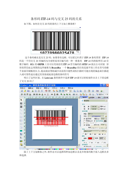
条形码ITF-14码与交叉25码的关系
如下图:如何在交叉25码的条码上下方加上横条框?
这个条码确实是交叉25码,如果带有边框,可以把它归类于ITF-14条码类型。
ITF-14码是一个用交叉25码编码为全球贸易项目编号的一种一维条码。
ITF-14码将始终用14位数字编码。
GS1的GEPIR工具可以用来给用ITF-14符号编码的GTIN-14找出公司识别。
厚厚的黑色标志周围的边界被称为BearerBar。
一个BearerBar的目的是扳平的工作在符号的整个表面印刷板的压力,提高阅读帮助减少误读的可能性或短扫描时可能出现的偏态束扫描进入或可靠性退出通过其顶部或底部边缘的条码符号。
明白了这些区别,在Label mx条码软件中选择ITF-14就可以轻松制作出含上下的边框了交叉25码了。
除了上下方加横条之外,软件还可以选择四种加边框以及是否将条码数字放入边框内多种选择.
遇到同样问题的朋友可以试着使用上述方法来解决。
- 1、下载文档前请自行甄别文档内容的完整性,平台不提供额外的编辑、内容补充、找答案等附加服务。
- 2、"仅部分预览"的文档,不可在线预览部分如存在完整性等问题,可反馈申请退款(可完整预览的文档不适用该条件!)。
- 3、如文档侵犯您的权益,请联系客服反馈,我们会尽快为您处理(人工客服工作时间:9:00-18:30)。
GS25/30T24Family25/30W DC-DC CONVERTER FAMILYDecember 19931/5Type V in V out I out GS25T24-518to 36V 5V 5A GS30T24-1218to 36V 12V 2,5A GS30T24-1518to 36V15V2AFEATURESMTBF in excess of 1M hours at +45°C ambient temperatureWide input voltage range (18to 36V)No external component required High efficiency (see data)Non latching permanent short-circuit protection Overvoltage protection Redundant operationRemote output voltage sense Remote INHIBIT/ENABLE Soft-startMinimized reflected input current Reverse input polarity protection Peak input overvoltage withstandNo derating over the temperature range500V DC minimum isolation between input and outputPCB or chassis mountableDESCRIPTIONThe GS25T24-5,GS30T24-12and GS30T24-15are isolated DC-DC converters designed for gen-eral purpose application.The output power is in the range of 25W to 30W.To ensure very long life,these converters do not use electrolytic aluminum capacitors or optoelec-tronic feedback systems.ABSOLUTE MAXIMUM RATINGSSymbol ParameterValue Unit V i DC Input Voltage17to 38VV V ipk Input Transient Overvoltage (t ≤1sec.)45V V ir Input Reverse Voltage 50V T stg Storage Temperature Range -55to +105°C T opOperating Temperature Range-25to +71°CELECTRICAL CHARACTERISTICS(T amb=25°C unless otherwise specified)Symbol Parameter Test Conditions Min Typ Max Unit V i Input Voltage Full Load182436VI i Input Current GS25T24-5Full Load1370mAGS30T24-12GS30T24-15Full Load1600I ir Input ReflectedCurrent V i=24V Full Load40mAppI isc Input Short-circuitCurrent GS25T24-5V i=24V360mA GS30T24-12V i=24V220GS30T24-15V i=24V200l iq Input QuiescentCurrent V i=24VConverter OFF5mAV inhl Low Inhibit Voltage V i=24V Full Load 1.2VV inhh High Inhibit Voltage V i=24V Full Load 1.8(open)V l inh Input Inhibit Current Vi=24V Full Load1mAV o Output Voltage GS25T24-5V i=24V Full Load4.955.00 5.05VGS30T24-12V i=24V Full Load11.8812.0012.12GS30T24-15V i=24V Full Load14.8515.0015.15V or Output Ripple andNoise Voltage V i=24VFull Load10mVppδV o Line Regulation V i=18to36VFull Load±0.001%δV o Load Regulation V i=24VFull Load to No Load±0.05%V oov Output OvervoltageProtection GS25T24-5V i=24V Full Load 6.8V GS30T24-12V i=24V Full Load15GS30T24-15V i=24V Full Load18δVo Remote Sense per Leg V i=18V0.5VTc TemperatureCoefficient V i=24V Full LoadOperating Temperature Range+0.02%/°CGS25/30T24FAMILY2/5Symbol Parameter Test Conditions Min Typ Max UnitI o Output Current GS25T24-5V i=18to36V05A GS30T24-12V i=18to36V0 2.5GS30T24-15V i=18to36V02I osck Output Current Limit GS25T24-5V i=24V Overload5.5AGS30T24-12V i=24V Overload2.75GS30T24-15V i=24V Overload2.2t ss Soft-start Time V i=24V Full Load30mst rt Transient RecoveryTime V i=24VStep Load ChangeδIo=25%75µsV is Isolation Voltage500Vdc f s Switching Frequency150kHzηEfficiency GS25T24-5V i=24V Full Load7578%GS30T24-12V i=24V Full Load7982GS30T24-15V i=24V Full Load8083R is Isolation Resistance109ΩR thc Thermal ResistanceCase to Ambient4°C/W ELECTRICAL CHARACTERISTICS(T amb=25°C unless otherwise specified)(cont’d)3/5GS25/30T24FAMILYPackage F.Dimensions in mm.(inches)CONNECTION DIAGRAM AND MECHANICAL DATA4/5PIN DESCRIPTIONPin FunctionDescription1-IN Negative input voltage.2+INPositive input voltage.Unregulated input voltage (typically 24V)must be applied between pin 1-2.The input section of the DC-DC converter is protected against reverse polarity by a series diode.No external fuse is required.Input is filtered by a Pi network.3ON/OFFLogically compatible with CMOS or open collector TTL.The converter is ON (Enable)when the voltage applied to this pin with reference to pin 1is higher than 1.8V.The converter is OFF (Inhibit)for a control voltage lower than 1.2V.When the pin is unconnected the converter is ON (Enable).4+SENSE Senses the remote load high side.To be connected to pin 6when remote sense is not used.5-SENSE Senses the remote load return.To be connected to pin 7when remote sense is not used.6+OUT Output voltage.7-OUTOutput voltage return.GS25/30T24FAMILYGS25/30T24FAMILY Information furnished is believed to be accurate and reliable.However,SGS-THOMSON Microelectronics assumes no responsibility for theconsequences of use of such information nor for any infringement of patents or other rights of third parties which may result from its use.No license is granted by implication or otherwise under any patent or patent rights of SGS-THOMSON Microelectronics.Specification mentioned in this publication are subject to change without notice.This publication supersedes and replaces all information previously supplied. SGS-THOMSON Microelectronics products are notauthorized for use as critical component s in life support devices or systems without expresswritten approval of SGS-THOMSON Microelectronics.©1994SGS-THOMSON Microelectronics–All Rights ReservedSGS-THOMSON Microelectronics GROUP OF COMPANIESAustralia-Brazil-France-Germany-Hong Kong-Italy-Japan-Korea-Malaysia-Malta-Morocco-The Netherlands-Singapore-Spain-Sweden-Switzerland-Taiwan-Thailand-United Kingdom-U.S.A.5/5。
