EN 1337-2中文
LNR系列水平力分散型橡胶支座

〖LNR 系列水平力分散型橡胶支座〗
设计指南
LNR 固定型——支座与墩、梁之间采用套筒连接,支座底面不设预埋钢板,上、下封层钢
板和套筒之间采用锚固螺栓连接,上预埋钢板和套筒之间采用配合焊接。固定型支座结构示意图如 下:
图4
LNR 水平力分散型橡胶支座结构示意图(固定型)
LNR 滑动型——支座与梁之间采用锚固钢筋连接,支座底面不设预埋钢板,上预埋钢板和
图1
普通板式橡胶支座撕裂
图2
普通板式橡胶支座滑移
图3
普通板式橡胶支座滑出
〖LNR 系列水平力分散型橡胶支座〗
设计指南
3. LNR 系列橡胶支座研制
〖LNR系列水平力分散型橡胶支座〗是按照国家标准GB 20688.2-2006及相关行业规范,同时 参照欧洲标准研制的新型桥梁构件系列产品,属国家专利技术成果(ZL 201120279078.3) ,适用于 7度(0.10g)及以下地震烈度区的各类公路及市政桥梁。 〖LNR系列水平力分散型橡胶支座〗是在充分调研GYZ、GJZ等系列板式橡胶支座产品及使用 现状的基础上, 借鉴了“水平力分散”的工作原理而开发的一种性能优异的新型板式橡胶支座。 它在常 规叠层橡胶支座的基础上做了较大的改进和创新,能满足较大的剪切位移,且与主梁、墩台进行有 效连接,确保桥梁上部结构有效传力至下部结构,实现了桥梁下部结构水平力分散,各墩协同抵抗 水平力。
〖LNR 系列水平力分散型橡胶支座〗
设计指南
2. 桥梁支座的发展及现状
我国改革开放以来,桥梁建设的规模日益壮大,也出现了更多、更先进的新桥型,桥梁的长大 化更为明显。作为桥梁组成构件之一的支座,用量越来越大,使用范围越来越广,形式也越来越多, 对桥梁支座的耐久性和使用性等也提出了更高的要求。鉴于此,不少桥梁工作者,在深入调查分析 以往各类支座存在的问题基础上,借鉴国内外成功经验,对国内已有支座的结构形式和构成材料等 不断加以改进,从而研发出了多种新型支座,以适应现代桥梁建设的高端需求。 板式橡胶支座是由多层薄钢板与多层橡胶片硫化粘合而成的一种普通橡胶支座产品,它具有构 造简单、加工制造容易、用钢量少、成本低廉、安装方便等优点。 目前, 市场上常用的板式橡胶支座主要有 GYZ、 GJZ 系列板式橡胶支座, 满足 JT/T 4-2004 《公 路桥梁板式橡胶支座》行业标准,该支座产品有相当长的应用历史和很多工程案例,但由于其在结 构与性能上的缺陷,特别是行业市场(竞争)现状,在已使用的工程中出现了诸多质量问题。总结 起来主要存在如下问题: 1、只能满足较小剪切位移,不能适应温度、地震及其它水平力作用下的较大剪切位移要求,支 座易发生撕裂,如图 1 所示; 2、仅靠摩擦作用未与主梁和桥墩进行有效连接,支座在较大水平力作用下有可能滑移、破坏或 失效,主梁的受力难以保证,主梁的位移会进一步增大,产生不可恢复的变形,易发生落梁,支座 滑移和滑出如图 2 和图 3 所示; 3、橡胶保护层较薄,在严寒、高温暴晒等长期恶劣环境下容易破坏,耐久性较差; 4、准入门槛低、生产企业多,引发恶性竞争,产品质量参差不齐,危及工程安全。
胶粘剂固化时间测试标准
胶粘剂固化时间测试标准
胶粘剂固化时间测试是评估胶粘剂在一定条件下固化或硬化所需的时间。
这种测试有助于确定胶粘剂在特定环境条件下的固化速度和性能。
以下是一些常见的用于胶粘剂固化时间测试的标准:
1. ASTM D1002-10:这个标准规范了胶粘剂的剪切强度和固化时间的测试方法。
该方法使用机械试验机来测试胶粘剂在一定时间内的固化情况。
2. ISO 4587:2013:这是国际标准化组织制定的用于胶粘剂的固化时间测试的标准。
它涵盖了胶粘剂固化时间测试的方法和要求。
3. ASTM D1337-05:这个标准描述了测量不同胶粘剂固化时间的试验方法。
4. EN 12003-2:欧洲标准,用于评估硬化胶粘剂的时间。
这些标准通常涵盖了胶粘剂固化时间测试的实验设备、样品准备、测试方法和结果评估等方面的内容。
测试可以在特定温度、湿度或其他环境条件下进行,以模拟实际使用中的固化情况。
通过测试胶粘剂的固化时间,可以评估其在特定工艺或应用中的适用性,并为生产和质量控制提供指导。
EN1337-1-2000结构支座一般设计规则全中文版

消,在这种情况下 μk 值取为 0。 连接处防止滑动的安全装置对于橡胶支座来说没有积极的意义,它可以根据 prEN1337-3 进 行检查。
5.3、安装条件 见 EN 1337-11 任何特殊的安装条件在支座运输时应该得到采购方与制造商的书面确认同意。
5.4、增加的位移量 除非 ES 或者其它相关的欧标有更严格的规定,为了确保有足够的可靠性,支座不会成为不 稳定的,或者按要求停止,设计位移量按下面的要求增加: a) 转动量
+/‐0.005 弧度或者+/‐10/r 弧度,两者取大值(r 单位为 mm) b) 平移量
如果支座没有机械限位,对于纵向位移大于+/‐50mm,横向位移大于+/‐20mm 的支座,两 个方向上各增加+/‐20mm 的位移量 这些要求仅仅为了满足位移量的要求,在应力计算的时候不能使用。并且不适用于橡胶支 座。 5.5、强度分析时最小位移量的假定 支座强度分析时合成的转动量应不小于+/‐0.003 弧度,合成的平移量不小于+/‐20mm, 或者橡胶支座不小于+/‐10mm。 如果支座不能绕一根轴转动,应该假定垂直于轴线的最小偏心距为 l/10。L 为垂直于轴 线的支座总长。
EN13372(2004年1月版)

EUROPEAN STANDARD NORME EUROPÉENNE EUROPÄISCHE NORMFINAL DRAFT prEN 13372January 2004ICS 35.240.60Will supersede ENV 13372:1999English versionRoad Transport and Traffic Telematics (RTTT) - Dedicatedshort-range communication - Profiles for RTTT applicationsTélématique des transports routiers - Communication àcourte portée véhicule/infrastructure - Profils pour les applications de télématique routièreStraßentransport- und Verkehrstelematik (RTTT) -Nahberiechskommunikation Fahrzeug-Bake (DSRC) -DSRC-Profile für RTTT-AnwendungenThis draft European Standard is submitted to CEN members for formal vote. It has been drawn up by the Technical Committee CEN/TC 278.If this draft becomes a European Standard, CEN members are bound to comply with the CEN/CENELEC Internal Regulations which stipulate the conditions for giving this European Standard the status of a national standard without any alteration.This draft European Standard was established by CEN in three official versions (English, French, German). A version in any other language made by translation under the responsibility of a CEN member into its own language and notified to the Management Centre has the same status as the official versions.CEN members are the national standards bodies of Austria, Belgium, Cyprus, Czech Republic, Denmark, Estonia, Finland, France, Germany, Greece, Hungary, Iceland, Ireland, Italy, Latvia, Lithuania, Luxembourg, Malta, Netherlands, Norway, Poland, Portugal, Slovakia, Slovenia, Spain, Sweden, Switzerland and United Kingdom.Warning : This document is not a European Standard. It is distributed for review and comments. It is subject to change without notice and shall not be referred to as a European Standard.EUROPEAN COMMITTEE FOR STANDARDIZATIONC O M I TÉE U R O PÉE NDE N O R M A LI S A T I O NEUR OPÄIS C HES KOM ITEE FÜR NOR M UNGManagement Centre: rue de Stassart, 36 B-1050 Brussels© 2004 CEN All rights of exploitation in any form and by any means reservedworldwide for CEN national Members.Ref. No. prEN 13372:2004: EprEN 13372:2004 (E)Contentspage Foreword (3)Introduction (4)1Scope (5)2Normative references (6)3Terms and definitions (7)4Abbreviation (8)5DSRC profiles overview (9)6DSRC parameters and subsets (10)6.1Physical layer (10)6.2Data link layer (11)6.3Application layer (12)6.4Interlayer subsets (12)7DSRC procedures (15)7.1Initialisation (15)7.2Late response (16)7.3Termination (17)8DSRC profiles (18)8.1DSRC profiles 0 and 1 (18)8.2Private profiles (18)Annex A (informative) A-deviations (19)2prEN 13372:2004 (E)ForewordThis document (prEN 13372:2004) has been prepared by Technical Committee CEN/TC 278, "Road Transport and Traffic Telematics", the secretariat of which is held by NEN.This document is currently submitted to the Formal Vote.This document will supersede ENV 13372:1999.Annex A is informative.3prEN 13372:2004 (E)IntroductionThis European Standard replaces ENV 13372. In order to facilitate migration from European Pre-standard (ENV) to European Standard, equipment procured and installed in accordance with ENV 13372 has been considered when drafting this European Standard. Operation of such equipment and procurement of additional equipment for systems based on such equipment can continue with reference to Directive 93/36/EEG Article 8 item 3c.This European Standard forms part of a series of European Standards defining the framework of a Dedicated Short Range Communication (DSRC) link in the Road Transport and Traffic Telematics (RTTT) environment.The communication requirements of many RTTT applications can be fulfilled by DSRC. The DSRC Standards enable compliant communication systems to serve multiple RTTT applications in parallel.The small service areas and severe real-time constraints require a specific protocol architecture leading to the reduced protocol stack shown in Figure 1, consisting of the Application Layer, the Data Link Layer, and the Physical Layer. Such an architecture is very common for real-time environments.This European Standard deals with the interlayer management of the DSRC protocol stack.Figure 1 — DSRC protocol stackThe following set of European Standards for the DSRC link is issued by CEN:prEN 12253Road transport and traffic telematics - Dedicated short-range communication - Physical layer using microwave at 5,8 GHzEN 12795Road transport and traffic telematics - Dedicated short-range communication - Data link layer: medium access and logical link controlEN 12834Road transport and traffic telematics - Dedicated short-range communication - Application layer prEN 13372Road transport and traffic telematics (RTTT) – Dedicated short-range communication - Profiles for RTTT applications(this European Standard)4prEN 13372:2004 (E) 1 ScopeThis European Standard specifies DSRC profiles which provide coherent sets of communication tools for applications based on DSRC. These sets consist of subsets of functionality described in prEN 12253, EN 12795 and EN 12834, out of which a minimum subset is mandatory.The DSRC Standards prEN 12253, EN 12795 and EN 12834, which together form a three-layered architecture for DSRC, are designed to encompass a wide range of services for different purposes in order to make the basic DSRC architecture suited for many different applications and for a wide range of possible products and systems. DSRC systems can be built using one-way (downlink) or two-way (interactive) communication. The DSRC profiles described in this European Standard are intended for interactive DSRC systems based on two-way communication and DSRC systems using one-way communication (broadcast services).While prEN 12253 contains very little variation, EN 12795 and especially EN 12834 describe a wide range of communication services. It has not been considered feasible to assume that any one piece of equipment is designed to implement all of these services. It is often the case that the functionality of the on board unit is more limited than the functionality of the roadside unit.This European Standard covers—Physical Layer parameter values—Data Link Layer subsets—Application Layer subsets—Initialisation procedures— Late response procedures— Termination procedures5prEN 13372:2004 (E)2 Normative referencesThis European Standard incorporates by dated or undated reference, provisions from other publications. These normative references are cited at the appropriate places in the text and the publications are listed hereafter. For dated references, subsequent amendments to or revisions of any of these publications apply to this European Standard only when incorporated in it by amendment or revision. For undated references the latest edition of the publication referred to applies (including amendments).prEN 12253Road transport and traffic telematics - Dedicated short-range communication - Physical layer using microwave at 5,8 GHzEN 12795Road transport and traffic telematics - Dedicated Short Range Communication (DSRC) -DSRC data link layer: medium access and logical link controlEN 12834Road transport and traffic telematics - Dedicated Short Range Communication (DSRC) -DSRC application layerprEN ISO 14906Road transport and traffic telematics - Electronic fee collection - Application interface definition for dedicated short-range communication (ISO/DIS 14906:2002)6prEN 13372:2004 (E) 3 Terms and definitionsFor the purposes of thisEuropean Standard, the following terms and definitions apply.3.1Applicationset of processes including related functions and structured data that uses the services offered by the DSRC communication stack3.2Beacon service tabledata structure transmitted by the RSU to indicate available services3.3Communication initialisationprocedure used to establish communication between an RSU and a newly arrived OBU3.4Downlink communicationcommunication from the RSU to the OBU3.5DSRC profileconsistent and standardised set of cross layer parameters in a specific DSRC implementation. Identified by a unique number.3.6Interlayer managementassembly of communication parameters of all protocol layers such that a consistent communication protocol is provided3.7On Board Unit (OBU)physical assembly that is located and operated in or on the vehicle to transmit and/or receive DSRC signals. It may be in a form that is removable from the vehicle, or mountable in or on any part of the vehicle structure, or bonded to a part of the vehicle, or an integral part of a vehicle component, such as a windscreen, bumper or licence plate. In this European Standard, parameters that refer to an OBU relate to the form that the OBU takes as it is supplied to the vehicle manufacturer or constructor.3.8Roadside Unit (RSU)DSRC equipment usually residing by the side of the road or overhead the road3.9Terminationthe procedure used to terminate communication between a RSU and an OBU3.10Uplink communicationcommunication from the OBU to the RSU3.11Vehicle service tabledata structure transmitted by the OBU to indicate available services7prEN 13372:2004 (E)4 AbbreviationACn Acknowledged Command with sequence bit n APDU Application Protocol Data UnitBST Beacon Service TableCEN European Committee for Standardisation DSRC Dedicated Short-Range CommunicationEC European CommissionE.I.R.P.Equivalent Isotropic Radiated PowerEFC Electronic Fee CollectionEN European StandardENV European pre-StandardL1Layer 1 of DSRC (Physical Layer)L2Layer 2 of DSRC (Data Link Layer)L7Layer 7 of DSRC (Application Layer)LID Link IDLLC Logical Link ControlMAC Medium Access ControlNEN Standards institute of The NetherlandsOBU On Board UnitRSU RoadSide UnitRTTT Road Transport and Traffic TelematicsTC Technical CommitteeUI Unnumbered InformationUNI Standards institute of ItalyVST Vehicle Service Table8prEN 13372:2004 (E) 5 DSRC profiles overviewIn the European DSRC Standards each consistent and standardised set of communication protocol parameter values is called a DSRC profile and is assigned a unique identifier number. The word profile is a reserved word in EN 12834 and is used in the definition of the BST and VST.Each profile is made up of a set of parameter values and/or functionality from each layer.Profiles are not registered but defined by this European Standard. Future extension of the number of profiles defined by this European Standard, made necessary by the introduction of new application and/or configurations, will be undertaken by means of revision of this standard.When OBUs arrive at the DSRC communication zone, the use of one profile is negotiated between the RSU and the OBU. The initialisation and negotiation procedure is described in EN 12834.Each DSRC profile is identified by a unique number of ASN.1 type "Profile". One or more DSRC profile numbers are broadcasted by the RSU in the BST according to site-specific rules. Only OBUs being able to use at least one of the DSRC profiles offered by the RSU are allowed to answer, see clause 7.1.2 and EN 12834.This issue of prEN 13372 defines two closely related profiles differing only in one parameter of prEN 12253 (i.e. the Sub-carrier Frequency on uplink) while using the same subsets of functionality from EN 12795 and EN 12834. Future revisions of this European Standard may introduce additional profiles using other subsets of functionality from prEN 12253, EN 12795 and EN 12834. This European Standard also allows for private profiles enabling system implementers to realise additional functionality not provided by profile content defined in this European Standard or a subsequent revision of this European Standard.9prEN 13372:2004 (E)106 DSRC parameters and subsets6.1 Physical layer6.1.1 OverviewprEN 12253 specifies the physical layer parameters for uplink and for downlink. For some parameters there are alternative values. Wherever the exact choice of one value among its alternatives needs to be made known to the communication partner, profiling is used to define which of the alternative values is chosen and the profile number indicates the choice to the communication partner. The alternative values are listed in Table 1.Table 1 — Physical layer parameters with alternative valuesParameter ValuesCommentD1Downlink CarrierFrequenciesThere are four alternatives:5,7975, 5,8025,5,8075 and 5,8125 GHzCarrier Frequencies may be selected by theimplementer of the roadside system and need not be known in the OBU.D2RSUTransmitterSpectrum MaskThere are three alternatives:class A, B or C.Parameter for controlling interference between RSUs. A suitable class may be selected by the implementer of the roadside system and need not be known in the OBU. OBUs shall be able to function properly with any class of RSU.Class A shall not be used in new installations.D11aPower Limit for communication (upper)There are two alternatives:D11a-0: -24 dBm or D11a-1: -17 dBm The alternative to be chosen is stated in 6.1.2 for Set L1-A and 6.1.3 for Set L1-B.D12Cut-off power level of OBU -60 dBmThis parameter applies only for “Set B OBUs”.U1Sub-carrier FrequencyThere are two alternatives:1,5 MHz or 2,0 MHz.An OBU shall support 1,5 MHz and 2,0 MHz.Selection of sub-carrier frequency in OBU depends on Profile indicated by the RSU. Forinteroperability with existing installations it is recommended that a 1,5 MHz sub-carrier frequency is used wherever possible.U2OBU Transmitter Spectrum Mask There are two alternatives:U2(3)-0 = -39 dBm or U2(3)-1 = -35 dBm The alternative to be chosen is stated in 6.1.2 for Set L1-A and 6.1.3 for Set L1-B.U4aMaximum Single Side Band E.I.R.P.(bore sight)There are two alternatives:U4a-0: -14 dBm or U4a-1: -21 dBmThe alternative to be chosen is stated in 6.1.2 for Set L1-A and 6.1.3 for Set L1-B.U4b Maximum Single Side Band E.I.R.P.(35°)There are two alternatives:U4b-0: no requirement U4b-1: -17 dBmThis parameter applies only for “Set B OBUs”.U12b Conversion Gain (upper limit)10 dB for each side bandThis parameter applies only for “Set B OBUs”.6.1.2 Set L1-ATable 2 is a summary of the set of alternative values of physical layer parameters selected as set L1-A.Table 2 — Physical layer parameter set L1-A (“Set A OBU”)Parameter Values D1Downlink Carrier Frequencies According to Table 1D2RSU Transmitter Spectrum Mask According to Table 1D11a Power Limit for communication (upper)D11a-1: -17 dBmD12Cut-off power level of OBU Not applicableU1Sub-carrier Frequency An OBU shall support 1,5 MHz and 2,0 MHz.U2OBU Transmitter Spectrum Mask U2(3)-0: -39 dBmU4a Maximum Single Side Band E.I.R.P. (bore sight)U4a-1: -21 dBmU4b Maximum Single Side Band E.I.R.P. (35°)Not applicableU12b Conversion Gain (upper limit)Not applicableInteractive profiles using physical layer parameter set L1-A are defined in pairs, where each pair consists of one profile using U1 = 1,5 MHz and one profile using U1 = 2,0 MHz.6.1.3 Set L1-BTable 3 is a summary of the set of alternative values of physical layer parameters selected as set L1-B.Table 3 — Physical layer parameter set L1-B (“Set B OBU”)Parameter Values D1Downlink Carrier Frequencies According to Table 1D2RSU Transmitter Spectrum Mask According to Table 1D11a Power Limit for communication (upper)D11a-0: -24 dBmD12Cut-off power level of OBU D12-1: -60 dBmU1Sub-carrier Frequency An OBU shall support 1,5 MHz and 2,0 MHz.U2OBU Transmitter Spectrum Mask U2(3)-1: -35 dBmU4a Maximum Single Side Band E.I.R.P. (bore sight)U4a-0: -14 dBmU4b Maximum Single Side Band E.I.R.P. (35°)-17 dBmU12b Conversion Gain (upper limit)10 dBInteractive profiles using physical layer parameter set L1-B are defined in pairs, where each pair consists of one profile using U1 = 1,5 MHz and one profile using U1 = 2,0 MHz.6.2 Data link layer6.2.1 OverviewEN 12795 specifies the services offered by the data link layer. It contains LLC services, namely acknowledged and unacknowledged commands and responses, and MAC services, namely window request and allocation. For details of the LLC and MAC services and service primitives see EN 12795.The following subclause defines a subset, set L2, of the services provided by EN 12795.6.2.2 Set L2Acknowledged and unacknowledged commands are allowed.Unacknowledged commands may be issued by the RSU or by the OBU.Acknowledged commands shall only be issued by the RSU.Private uplink windows shall only be requested in frames having no LPDU.Private uplink window request shall only be sent in public uplink windows.Further restrictions according to 6.4 apply.6.3 Application layer6.3.1 OverviewEN 12834 specifies the services offered by the application layer. It contains the Initialisation Kernel service, named Initialisation, and Transfer Kernel services, namely Set, Get, Action and Event_Report. Each service offers four service primitives, namely request, indication, response and confirm. For details of the structure of application layer service primitives see EN 12834.The following subclause defines a subset, set L7, of the services provided by EN 12834.6.3.2 Set L7Confirmed and unconfirmed requests are allowed.All requests shall be issued by the RSU, while any responses shall be issued by the OBU.The possibility of extending the value range of certain data types, namely DSRCApplicationEntityID, Dsrc-EID, Profile, ActionType and fileID and the possibility of extending the length of lists beyond 127 shall not be used.In the BST, the Application List shall contain a sequence of data element 'aid'. The optional elements 'eid' and'parameter' shall not be present.If profile 0 is supported by the RSU then the value of data element Profile in BST shall be 0.If profile 1 is supported by the RSU then the value of data element Profile in BST shall be 1.In the VST, the Application List shall contain a sequence of sequences consisting of data elements 'aid', 'eid' and 'parameter'.Further restrictions according to 6.4 apply.6.4 Interlayer subsets6.4.1 OverviewEN 12795 and EN 12834 specify the protocol services for DSRC. It is desirable that the use of certain services in the application layer is connected with the use of certain services of the data link layer. The set of connected application layer and data link layer services is called Interlayer subset.6.4.2 Set IntFrames, containing other combinations of functionality than that described below shall not be used.Table 4 — Supported downlink frames of set IntDownlink Framesno LID MAC LLC APDU Remarks RSU OBE 1Private20/28none none Private Uplinkwindow allocationM M2Broadcast A003INIT.request (BST)Broadcast UI commandwith window allocationM M3Broadcast8003SET. request, mode = 0ACTION.request, mode = 0Broadcast UI commandno window allocationopt opt4Private8003SET. request, mode = 0ACTION. request, mode = 0Private UI commandno window allocationopt opt5Private8003EVENT_REPORT. request(RELEASE), mode = 0Private UI commandno window allocationM M6Private A0/A867/E7none (DL_ECHO)SET. request, mode = 0ACTION. request, mode = 0Private AC commandwith p = 0with window allocationopt opt7Private A0/A877/F7GET. RequestSET. request, mode = 1ACTION. request, mode = 1Private AC commandwith p = 1with window allocationopt optM Indicates that it is mandatory to support the frameOpt RSU Indicates that it is optional to support the frameOpt OBU Indicates that it is optional to support the frame, and that the Application Context Mark(s) or other information contained in the VST can be used to deduce whether the frame is supported or notTable 5 — Supported uplink frames of set IntUplink Framesno LID MAC LLC LLCstatusAPDU Remark RSU OBE 1Private60None None none Private uplink window request(in public uplink window only)M M2Private C003None INIT.response (VST)Private UI commandno window request (VST)M M3Private C003None GET. response,SET. response,ACTION. response Private UI commandno window requestopt opt4Private D067/E740none(DL_ECHO)Private ACn response f = 0no window requestopt opt5Private D077/F730none(APDU not available)Private ACn response f = 1no window requestopt opt6Private D077/F700GET. response,SET. response,ACTION. response Private ACn response f = 1no window requestopt opt7Private D067/E710none Private ACn response f = 0no window request.Acknowledgement of acommand not understood bythe OBU.Different solutions for thisfunction are also allowed.opt optM Indicates that it is mandatory to support the frameOpt RSU Indicates that it is optional to support the frameOpt OBU Indicates that it is optional to support the frame, and that the Application Context Mark(s) or other information contained in the VST can be used to deduce whether the frame is supported or not7 DSRC procedures7.1 Initialisation7.1.1 Detailed procedureThe Initialisation procedure is partly described in EN 12834.a) In order to invite OBUs for initialisation, the RSU shall transmit a frame with the following content:no LID MAC LLC APDU Remark1Broadcast A003INIT.request (= BST)Broadcast UI command, window allocationb) If the conditions for continuing Initialisation are fulfilled (see EN 12834) the OBU shall transmit, in one of thepublic uplink windows allocated according to EN 12795, a frame with the following content:no LID MAC LLC APDU Remark2Private60none none Private uplink window requestc) The RSU receiving the private uplink window request shall transmit a frame with the following content:no LID MAC LLC APDU Remark3Private20/28none none Private uplink window allocationd) The OBU shall transmit, in the window allocated by the above frame, a frame with the following content:no LID MAC LLC APDU Remark4Private C003INIT.response (= VST)Private UI command, no window requestUnless the OBU receives another privately addressed frame containing an APDU, before receiving the next BST, it shall repeat the procedure from step b.7.1.2 Use of certain data elements of BSTThe reception and interpretation of the BST allows the OBU to adapt its behaviour to the capabilities of the RSU. Table 6 contains the important data elements from EN 12834 with explanations of use.Table 6 — Selected data elements of the BST with explanationBST Explanation BehaviourBeacon Id /Time Unambiguos identifier of the RSU /Current time.The OBU shall only initialise if certain conditionsare met. See EN 12834Profile / ProfileList Identifier for the DSRC profile thatthe RSU makes available to OBUsto use for communication.The OBU shall only initialise if it can support atleast one of the available DSRC profile.DSRC Application EntityID Identifier for the type of applicationthat the RSU is prepared for.The OBU shall only initialise if it has at least oneelement supporting the type of application7.1.3 Use of certain data elements of VSTThe reception and interpretation of the VST allows the RSU to adapt its behaviour to the capabilities of the OBU. These capabilities may consist of sets of service primitives, which the OBU can understand and/or sets of data, which need to be present in the OBU in order to complete the exchange of data. It may also consist of other resources that the RSU may need to use.There are a number of important data elements of the VST that may aid the RSU in adapting its behaviour to different OBUs. Table 7 contains the important data elements from EN 12834 with explanations of use.Table 7 — Selected data elements of the VST with explanationVST Explanation BehaviourProfile Identifier for the DSRC profile that theOBUs will use for communication.The RSU shall set the communication profiles for the communication with this OBU.DSRC Application EntityID Identifier for the type of application thatthe OBU can support.The OBU shall indicate that it can support thetype of application that the RSU is prepared for.The RSU shall prepare to manage the indicatedtype of application.Dsrc-EID Identifier for the element in the OBUthat can support this type of application.The OBU shall indicate by which element(s) it can support the type of application.The RSU shall prepare to use the indicated local addresses of elements related to the application requested for subsequent usage.Application Context Mark Provides unique information about theapplication context.An example of Application ContextMark content is the EFC Context Markas specified in prEN ISO 14906.The OBU shall indicate how it can support thetype of application.The RSU shall prepare to manage the indicatedimplementation of the application.The RSU shall only proceed with interactivecommunication if it recognises at least one ofthe Application Context Marks presented by theOBU.Manufacturer ID Manufacturer ID is a unique identifier ofthe company or organisation that hasmanufactured the OBU.Manufacturer Id is a registered itemaccording to EN 12834The RSU may use this information to adapt its behaviour to the resources of the OBUEquipment Class Equipment Class is an identifier of thetype of equipment or of the capabilitiesof the OBU. To be interpreted togetherwith Manufacturer Id.The RSU may use this information to adapt its behaviour to the resources of the OBU7.2 Late response7.2.1 GeneralWhen the OBU receives an ACn command containing a request in confirmed mode it is expected to return an APDU in the response. Normally this response shall be transmitted in the window allocated by the downlink frame. According to EN 12795 there is a fixed maximum time by which the OBU can delay its response. It may happen that the OBU has not been able to process the command and prepare the response before that time is passed. For these cases the procedure of 7.2.2 or that of 7.2.3 can be used.7.2.2 Procedure IIf the situation defined in 7.2.1 occurs, the OBU may transmit an ACn response containing ACn Response Status Subfield equal to NE_OK and no APDU to indicate that the requested APDU is not available.The OBU can then continue processing the command and preparing the response.When the response is available in the OBU, the OBU may request a private uplink window. The RSU shall then allocate a private uplink window in which the OBU shall transmit the response using a UI command.Unless the OBU receives another privately addressed frame, containing an APDU, before receiving the next BST, it shall repeat the procedure from the transmission of the private uplink window request.NOTE: Should the downlink frame containing the original command be retransmitted by the RSU, the situation mayarise that at the time of reception of the retransmission the OBU has processed the command and prepared theresponse. It may then send the response immediately in the private uplink window allocated by the retransmission.7.2.3 Procedure IIIf the situation defined in 7.2.1 occurs the OBU may transmit an ACn response containing an APDU which is a response where ReturnStatus = 5 (processing) to indicate that the OBU is processing. In this case the finalisation of the procedure is application specific.7.3 TerminationThe Release procedure is described in EN 12834. When no DSRC application in the RSU needs to perform further communication with the OBU the RSU shall transmit a frame with the following content:no LID MAC LLC APDU Remarks1Private8003EVENT_REPORT. request(RELEASE), mode = 0Private UI command no window allocationThe OBU shall then delete its LID according to EN 12834.。
LNR系列水平力分散型橡胶支座

示 例2:
滑 动 型 矩 形 水 平 力 分 散 型 橡 胶 支 座 , 纵 桥 向 尺 寸 370mm, 横 桥 向 尺 寸 420mm, 高 度 147mm, 剪 切 模 量1.0MPa, 滑 动 位 移 量 为 ±100mm, 型 号 表 示 为 :LNR(H)-370×420×147e 1 0 0。
设计依据
《公路桥涵设计通用规范》(JTG D60-2004) 《城市桥梁设计荷载标准》(CJJ 77-98) 《公路钢筋混凝土及预应力混凝土桥涵设计规范》(JTG D62-2004) 《公路桥梁抗震设计细则》(JTG/T B02-01-2008) 《城市桥梁抗震设计规范》(CJJ 166-2011) 《橡胶支座:桥梁隔震橡胶支座》(GB 20688.2-2006) 《橡胶支座:隔震橡胶支座试验方法》(GB/T 20688.1-2007) 《公路桥梁高阻尼隔震橡胶支座》》(报批稿) 《Structural bearings- Par t 2: Sliding elements》(EN 1337-2:2005) 《Structural bearings- Par t 3: Elastomeric bearings》(EN 1337-3:2005) 《公路桥梁板式橡胶支座》(JT/T 4-2004) 《聚四氟乙烯大型板材规范》(GJB 3026-1997) 《Anti-seismic devices》(EN 15129-2009)
中国交通建设股份有限公司
w w w . Tu m u k e j i . c o m
LNR 系列水平力分散型橡胶支座
〖LNR系 列 水 平 力 分 散 型 橡 胶 支 座 〗 是 按 照 现 行 国 家 标 准 (GB 20688) 及 相 关 行 业 规 范 , 并 同 时 参 照 欧 洲 标 准 研 制 的 桥 梁 标 准 构 件 系 列 产 品 , 属 专 利 技 术 成 果 , 适 用 于7度 (0 . 1 0 g) 及 以 下 地 震烈度区的各类公路及市政桥梁。该产品是在充分调研多个系列普通板式橡胶支座的基础上,借鉴 了“水平力分散”的工作原理研制而成,主要解决了普通板式橡胶支座隔震性能差、剪切位移小、 无可靠连接以及质量管控难度大等问题,是常规桥梁工程的新选择!
鞍式支座标准书

鞍式支座标准书鞍式支座是一种常见的结构支撑方式,用于构造支架、梁架等工程结构中的连接。
鞍式支座通过在支架底部使用多个锥形接触点来实现支撑。
这种连接方式可以承受垂直和水平荷载,在减震和防止滑动方面也有很好的效果,因此被广泛应用于建筑和结构工程。
为了保证鞍式支座的质量和安全性,国内外发布了一些标准和规范,以下是一些代表性的标准书。
1.《GB/T 14370-2007钢制鞍型支座技术条件》该标准是中国国家标准,适用于钢制鞍型支座的制造和使用。
标准定义了鞍型支座的基本要求,包括材料、制造工艺、尺寸偏差、耐久性等方面。
标准要求制造商必须提供质量合格证明,并对使用过程中的检测和维护提供指导。
2.《EN 1337-5:2007桥梁结构的承接构件钢制鞍型支座》该标准是欧洲标准,定义了钢制鞍型支座的制造和使用要求。
标准规定了鞍型支座的基本结构和材料、制造工艺、尺寸与公差、检验和试验等方面。
标准还规定了鞍型支座的承载能力、初始摩擦力和滑动能力等指标,以及鞍型支座在使用过程中的维护规范。
3.《AASHTO LRFD桥设计规范》该规范是美国公路交通管理局发布的桥梁设计标准,适用于美国地区的桥梁设计和施工。
规范对鞍型支座的使用和应用提出了一些要求,包括材料、减震性能、滑移能力等方面。
此外对通行荷载、抗震能力、环境影响等方面都有详细的规定。
总的来说,鞍式支座作为结构支撑方式,在建筑和桥梁工程中应用广泛。
然而要确保鞍式支座质量和安全性,仍需要按照相应的标准和规范进行设计、制造和使用,以确保其可靠性和稳定性。
同时,对鞍式支座的使用和维护也需要严格遵守相应的规定,以确保其正常运行。
LNR系列水平力分散型橡胶支座设计指南
图 4 LNR 水平力分散型橡胶支座结构示意图(固定型)
LNR 滑动型——支座与梁之间采用锚固钢筋连接,支座底面不设预埋钢板,上预埋钢板和
锚固钢筋采用焊接,上封层钢板和上预埋钢板采用焊接连接。滑动型支座结构示意图如下:
图 5 LNR 水平力分散型橡胶支座结构示意图(滑动型)
3、按支座本体形状分类 圆形水平力分散型橡胶支座——支座本体平面形状为圆形; 矩形水平力分散型橡胶支座——支座本体平面形状为矩形。
支座本体的形状,可以划分为如下两种类型(参见下图):
中交第一公路勘察设计研究院有限公司
3
〖LNR 系列水平力分散型橡胶支座〗
设计指南
LNR 固定型——支座与墩、梁之间采用套筒连接,支座底面不设预埋钢板,上、下封层钢
板和套筒之间采用锚固螺栓连接,上预埋钢板和套筒之间采用配合焊接。固定型支座结构示意图如 下:
3.2 产品结构 1、按功能形式分类
固定型支座——支座位移通过橡胶剪切变形实现,橡胶的水平剪切能承受较大的水平力,
通过橡胶在水平方向的大位移剪切变形实现水平力分散的功能;
滑动型支座——支座位移通过顶面设置的聚四氟乙烯滑板与不锈钢板组成的滑移摩擦副实
欧盟家具需要做的测试

家具需要做的测试欧洲市场相关机械测试标准EN 1335-1: 办公家具–办公室工作椅–第一部分: 尺寸EN 1335-2: 办公家具–办公室工作椅–第二部分: 安全要求EN 1335-3: 办公家具–办公室工作椅–第三部分: 测试方法EN 1728: 家用–座椅–测试方法-强度和耐久测试prEN 12521: 家具- 强度,耐久和安全- 家用桌子的要求DIN 68877: 工作转椅; 安全要求测试EN 13761: 办公家具–访客椅EN 1730: 家用家具–桌子- 强度,耐久与平衡性测试方法EN 15372: 家具–强度,耐久与安全-非家用桌子要求EN 527-1: 办公家具–工作台和桌子- 第一部分: 尺寸EN 527-2: 办公家具–工作台和桌子- 第二部分: 机械安全要求EN 527-3: 办公家具–工作台和桌子- 第三部分: 平衡性和结构机械强度测试方法EN 14074: 办公家具–台,桌和储物家具- 可移动部件的强度和耐久测试方法EN 14073-1: 办公家具–储物家具- 第一部分: 尺寸EN 14073-2: 办公家具–储物家具- 第二部分: 安全要求EN 14073-3: 办公家具–储物家具- 第三部分: 平衡性和结构强度测试方法EN 13453-1: 家具–非家居使用双层床和高床–第一部分: 安全,强度和耐久要求EN 13453-2: 家具–非家居使用双层床和高床–第二部分: 测试方法EN 1023-1: 办公家具–屏风- 第一部分: 尺寸EN 1023-2: 办公家具–屏风- 第二部分: 机械安全要求EN 1023-3: 办公家具–屏风- 第三部分: 测试方法BS 4875-8 家具–强度和平衡性–非家居使用家具的平衡性测试方法户外家具欧洲市场相关机械测试标准EN 581-1: 户外家具–露营,家居和公共场合使用座椅和桌子–第一部分: 一般安全要求EN 581-2: 户外家具-露营,家居和公共场合使用座椅和桌子–第二部分: 座椅机械安全要求和测试方法EN 581-3: 户外家具-露营,家居和公共场合使用座椅和桌子–第三部分: 桌子机械安全要求和测试方法EN 1022: 家居–座椅–平衡性青少年/儿童家具欧洲市场相关机械测试标准EN 1729-1: 家具–教育机构使用座椅与桌子–第一部分: 功能尺寸EN 1729-2: 家具–教育机构使用座椅与桌子–第二部分: 安全要求与测试方法EN 716-1: 儿童家用轻便小床和折叠床–第一部分:安全要求EN 716-2: 儿童家用轻便小床和折叠床–第二部分:测试方法EN 14988-1: 儿童高脚椅- 第一部分:安全要求EN 14988-2: 儿童高脚椅- 第二部分:测试方法;EN 747-1: 家具–家居使用双层床和高床–第一部分: 安全,强度和耐久要求EN 747-2: 家具–家居使用双层床和高床–第二部分:测试方法EN 1130-1: 家具–家用婴儿床和摇篮- 第一部分:安全要求EN 1130-2: 家具–家用婴儿床和摇篮- 第二部分:测试方法EN 12221-1: 家居使用换尿布台–第一部分:安全要求EN 12221-2: 家居使用换尿布台–第二部分:测试方法家用家具欧洲市场相关机械测试标准EN 1730: 家用家具–桌子–强度,耐久和平衡性的测试方法prEN 12521: 家具- 强度,耐久和安全–家用桌子要求EN 1022: 家用–座椅–平衡性EN 1728: 家用–座椅–测试方法–强度和耐久prEN 12520: 强度,耐久和安全- 家用座椅要求EN 14749: 家用和厨房储物家具和操作面- 安全要求和测试方法EN 1725 : 家用家具–床和床垫–安全要求和测试方法BS 4875-1: 家具–强度和平衡性–家居座椅结构的强度和耐久要求BS 4875-5: 家具–强度和平衡性–家用手推车和桌子的强度,耐久和平衡性要求家具五金配件欧洲市场相关机械测试标准EN 15570: 家具五金- 铰链与其配件的强度和耐久测试–垂轴固定的门铰EN 15338: 家具五金- 可拉伸部件与其配件的强度和耐久测试EN 12529/12527: 脚轮。
LNR系列水平力分散型橡胶支座设计指南

图 4 LNR 水平力分散型橡胶支座结构示意图(固定型)
LNR 滑动型——支座与梁之间采用锚固钢筋连接,支座底面不设预埋钢板,上预埋钢板和
锚固钢筋采用焊接,上封层钢板和上预埋钢板采用焊接连接。滑动型支座结构示意图如下:
图 5 LNR 水平力分散型橡胶支座结构示意图(滑动型)
3、按支座本体形状分类 圆形水平力分散型橡胶支座——支座本体平面形状为圆形; 矩形水平力分散型橡胶支座——支座本体平面形状为矩形。
8.4.1 LNR 矩形滑动型系列 ........................................25 8.4.2 LNR 圆形滑动型系列 ........................................29
中交第一公路勘察设计研究院有限公司
目录
〖LNR 系列水平力分散型橡胶支座〗
7.4.1 LNR 矩形固定型系列 ........................................14 7.4.2 LNR 圆形固定型系列 ........................................18 8. 滑动支座安装、更换、养护及尺寸 ..................................... 21
3. LNR 系列橡胶支座研制 ................................................3
3.1 设计依据 .........................................................3 3.2 产品结构 .........................................................3 3.3 支座型号 .........................................................4 3.4 产品特点 .........................................................5 4. 支座技术性能 ........................................................ 5
公路桥梁盆式橡胶支座标准
公路桥梁盆式橡胶支座Pot-type elastomeric pad bearing for highway bridge1范围本标准规定了公路桥梁盆式橡胶支座的产品规格、分类、型号、技术要求;本标准适用于承载力为800KN~60000KN的桥梁盆式橡胶支座以下简称盆式支座;2引用标准下列标准所包含的条文,通过在本标准中引用而构成为本标准的条文;在标准出版时,所示版本均为有效;所有标准都会被修订,使用本标准的各方应探讨使用下列标准最新版本的可能性;GB 527-83 硫化橡胶物理试验方法的一般要求GB/T 528-92 硫化橡胶和热塑橡胶拉伸性能的测定GB/T 1591-92 低合金结构钢GB 1033-86 塑料密度和相对密度试验GB/T 1039-92 塑料力学性能试验方法总则GB/T 1040-92 塑料拉伸性能试验方法GB/T 1184-96 形状和位置公差未注公差的规定GB/T 1682-94 硫化橡胶低温脆性的测定——单试样法GB/T 1804-92 一般公差线性尺寸的未注公差EN1337-5,Annex A 内密封圈ASTM A240-316L 不锈钢冷轧钢板GB 3512-83 橡胶热空气老化试验方法GB 6031-85 硫化橡胶国际硬度的测定30-85IRHD常规试验法GB 7759-87 硫化橡胶在常温和高温下恒定形变压缩永久变形的测定GB 7762-87 硫化橡胶耐臭氧老化试验静态拉伸试验方法GB/T 8923-88 涂装前钢材表面锈蚀等级和除锈等级JB/T 5943-91 工程机械焊接件通用技术条件SYNTHESO-8002 硅脂3分类、型号及规格3.1分类按使用性能分类(1)双向滑动支座多向滑动支座:具有竖向承载、竖向转动和多向滑移性能,代号为TGA;(2)单向滑动支座:具有竖向承载、竖向转动和单一方向滑移性能,代号为TGE;(3)固定支座:具有竖向承载和竖向转动性能,代号为TF;型号支座型号表示方法如图1;图1例如:TGE4000KN:表示单向滑动支座,承载竖向载荷为4000KN;TGA1500KN:表示双向多向滑动支座,承载竖向载荷为1500KN;TF5000KN:表示固定支座,承载竖向载荷为5000KN;3.3 结构形式双向多向滑动支座和单向滑动支座由上顶板、不锈钢滑板、聚四氟乙烯滑板、中间钢板、密封圈、橡胶板、底盆等组成;单向滑动支座沿滑动方向还设有导向挡块;固定支座由上顶板、密封圈、橡胶板、底盆等组成;双向滑动支座结构示意见图2;单向滑动支座结构示意见图3;固定支座结构示意见图4;图2图3图44技术要求支座性能4.1.1竖向承载力本标准系列支座的竖向承载力为800KN~60000KN;4.1.2水平承载力本标准系列中,固定支座在各方向和单向滑动支座非滑移方向的水平承载力均不得小于支座竖向承载力的10%或按照客户的要求进行设计;4.1.3转角支座转动角度不得小于或按照客户要求进行设计;4.1.4摩阻系数加硅脂润滑后,常温型活动支座设计摩阻系数最小取;4.1.5位移根据具体参数;支座用材的物理机械性能若无特殊要求,按照以下性能指标4.2.1橡胶盆式支座用橡胶板应以氯丁橡胶、天然橡胶、或三元乙丙橡胶为原料,严禁使用再生的或加工研碎的硫化橡胶;橡胶板用胶料的物理机械性能见表1;表1橡胶板用胶料的物理机械性能4.2.2聚四氟乙烯板盆式支座用聚四氟乙烯板应是纯的模压板材,而非车削板材;加工原料不得用回头料或掺加任何填料;聚四氟乙烯板的物理机械性能应符合表2的要求;表2聚四氟乙烯板的物理机械性能4.2.3不锈钢板双向和单向滑动支座不锈钢滑板及单向滑动支座的侧向滑条采用316L不锈钢板,其化学成分及力学性能应符合ASTM A240的有关规定;钢板表面经镜面处理;板厚采用; 4.2.4硅脂聚四氟乙烯板用硅脂润滑;硅脂必须经过检验,应保证支座在使用温度范围内不会干涸,对滑移面材料不得有害,并具有良好的抗氧、耐腐蚀及防水性能;其性能指标应符合SYNTHESO-8002的有关规定;4.2.5钢件支座上顶板、中间钢板、底盆均采用Q345钢板,其性能应符合GB1591-92标准; 4.2.6内密封圈内密封圈采用Carbon-PTFE,其性能指标应符合EN1337-5,Annex A标准的规定; 4.2.7侧向滑条单向滑动支座中侧向滑条的物理机械性能应符合标准EN 1337-2 中 5.3.1 CM1中的有关规定;支座用材规格4.3.1橡胶板盆式支座用橡胶板直径偏差为~0,厚度偏差为0~+;4.3.2聚四氟乙烯板聚四氟乙烯板直径偏差为+~+,厚度偏差为0~+;聚四氟乙烯板的滑动面上应设有存放硅脂的储脂槽,储脂槽不能用机械方法成型,储脂槽的平面布置和尺寸见图5;图5支座用材的外观质量4.4.1橡胶板橡胶板外观不得有裂纹、掉块、损伤及鼓泡;4.4.2聚四氟乙烯板材聚四氟乙烯板材为树脂本色;板材表面应光滑,不允许有裂纹、气泡、分层;不允许有影响使用的机械损伤等缺陷;不允许夹带任何杂质;4.4.3不锈钢板不锈钢板不得有分层,表面不得有裂纹、气泡、杂质、结疤等影响使用的缺陷;4.4.4硅脂硅脂为乳白色脂状物,不允许有机械杂质;焊接焊接必须牢固,焊缝应光滑、平整、连续;焊接技术应符合JB/T5943有关要求;机加工件4.6.1支座各件加工严格按图样要求进行;4.6.2加工后的配合面及摩阻表面不允许有降低表面质量的印记;4.6.3零件加工后在搬运、存放时必须防止其表面受到损伤、腐蚀及变形;4.6.4图样中未注明公差的极限偏差应符合GB/T1804中的m级要求;4.6.5图样中未注明的形状和位置公差、平面度应符合GB/T1184中的K级规定,平行度应符合GB/T1184中的有关规定;支座防腐蚀4.7.1为提高支座使用寿命,支座钢件应进行防腐蚀处理;4.7.2钢件表面进行喷涂防锈蚀处理时,按如下要求进行:a待涂装表面应进行表面处理,首先清除附着于钢材表面的杂质,用稀释剂或清洗剂除去油污及脏物,并对边、角和焊缝进行打磨,如有腐蚀性盐类,应用清水冲洗干净并吹干其表面;b用喷射或抛射除锈法将待涂装表面的氧化皮、铁锈及其他杂质清除干净后,用真空吸尘器将钢材表面再清除一次;处理后机加工表面应达到GB/T8923中规定的级,处理后表面粗糙度要求为30μm~75μm;c在表面处理后4h内进行喷锌,以防处理表面生锈;喷锌厚度为 100μm,再喷涂环氧封闭漆,干膜厚度要求为25~40μm,中间层漆为环氧云铁,干膜平均厚度要求为80μm;面漆为环氧云铁,干膜平均厚度要求80μm;d施工中应经常使用湿膜测厚仪测定湿膜厚度,以控制干漆膜厚度并保证漆膜厚度均匀;漆膜厚度未达到要求处,必须补涂;支座组装4.8.1凡待装的零、部件,必须有质量检验部门的合格标记;外购件和协作件须有证明其合格的证件,方可进行装配;4.8.2凡已喷涂的零、部件,在油漆未干透前,不得进行装配;4.8.3零、部件装配前,必须将铁屑、毛刺、油污、泥沙等杂物清除干净;其配合面及摩阻表面不允许有锈蚀、碰伤和影响使用性能的划痕;相互配合的表面均应干净;4.8.4装配橡胶板和聚四氟乙烯板时,不得用锤直接敲击;若须敲击时,中间应垫以软垫或不易损伤橡胶板和聚四氟乙烯板表面的垫块;橡胶板下不应有空气垫层;4.8.5安装橡胶板前,盆腔内清除干净后均匀涂抹一层硅脂进行润滑;4.8.6活动支座上顶板和底盆组装前,应用丙酮或酒精将不锈钢滑板和聚四氟乙烯板擦洗干净,并在聚四氟乙烯板的储脂槽内注满硅脂;4.8.7支座外露表面应平整、美观、焊缝均匀;喷漆表面应光滑,不得有漏漆、流痕、皱褶等现象;4.8.8组装后支座高度偏差为0~+5mm;。
石材测试标准一览表
部分常见的测试项目如:Testing Items测试项目Testing Standard测试标准Testing Items测试项目Testing Standard测试标准Testing Items测试项目Testing Standard测试标准天然石--欧标EN1 岩相分析 petrographic description EN 12407:2007 7 防滑性Slip Resistance EN142312003 13 莫氏硬度mohs hardness EN 1012 吸水率water absorption EN13755:2002 8 毛细吸水率 water absorption coefficient by capillarity EN1925:1999 14 破坏能量rupture energy EN 14158-20043 表观密度和孔隙率 apparent density and open porosity EN1936:2006 9 抗冻性frost resistance EN12371:2001 15 尺寸测量dimension EN13373-20034 弯曲强度 flexural Strength EN12372:2006 10 温度冲击thermal shock resistance EN14066:2003 16 盐晶测试 Salt crystallization EN 12370:19995 抗压强度compressive strength EN1926:2006 11 销钉孔破坏载荷resistance to fixing (dowel hole) EN 13364:2002 17 盐雾测试Salt mist EN 14147-20036 耐磨性 abrasion resistance EN14157:2004 12 声速测试sound speed EN 14579:2004 18 二氧化硫老化 sulfur dioxide exposure EN 13919:2002适用于非洲有特殊要求的国家--欧标EN1 表观密度和孔隙率 apparent density and open porosity EN 1936:2006 3 抗折强度 flexural strength EN 12372:2006 4 毛细吸水率 water absorption coefficient by capillarity EN 772-11:20002 抗压强度 compressive strength EN 772-1:2000板岩(瓦板和文化石等)--欧标EN1 板岩岩相分析 petrographic description EN 12326-2:2004 5 吸水率water absorption EN 12326-2:2004 8 二氧化硫老化 sulfur dioxide exposure EN 12326-2:20042 厚度thickness EN 12326-2:2004 6 抗冻性 frost resistance EN 12326-2:2004 9 碳酸盐含量carbonate content EN 12326-2:20043 尺寸偏差 demension deviation EN 12326-2:2004 7 热循环thermal cycling EN 12326-2:2004 10 非碳酸盐碳含量 non-carbonate carbon content EN 12326-2:20044 弯曲强度bending Strength EN 12326-2:2004人造大理石--欧标EN1 表观密度和吸水率 water absorption and apparent density EN14617-1:2005 7 抗冲击性impact resistance EN 14617-9:2005 13 防火等级(A2级) reaction to fire EN 13501-12 弯曲强度flexural strength EN14617-2:2004 8 耐化学腐蚀性 chemical resistance EN 14617-10:2005 14 防滑性能slippliness EN 14231:20033 耐磨性Abrasion resistance EN14617-4:2005 9 线性热膨胀系数linear thermal expansion coefficient EN 14617-11:2005 15 莫氏硬度Mohs hardness EN 1014 抗冻性frost and thraw resistance EN14617-5:2005 10 尺寸稳定 dimensional stability EN 14617-12:2005 16 二氧化硅含量 Content of silicon dioxide5 温度冲击 thermal shock resistance EN14617-6:2005 11 抗压强度 compressive strength EN 14617-15:2005 17 白度测试 Whiteness6 销钉孔破坏载荷 resistance to fixing (dowel hole) EN 14617-8:2007 12 尺寸,几何特征和模石板的表面质量dimensions,geometric characteristics and surface quality of modular tiles EN 14617-16:2005天然石--美标ASTM1 抗压强度(干、湿) compressive strength ASTM C170-06 3 弯曲强度(干、湿) flexural Strength ASTM C880-06 5 断裂模数modulus of rupture ASTM C 99-062 吸水率及密度absorption by weight andgravity ASTM C 97-02 4 耐磨性abrasion resistance ASTM C 241-05板岩--美标ASTM1 吸水率 water absorption ASTM C 121-06 3 光泽度specular Gloss ASTMD523 5 热膨胀系数thermal expansion ASTM D45352 断裂模数modulus of rupture ASTM C120 4 防滑性能 surface frictional properties ASTM E303实体面材(人造石)--美标ANSI1 载荷测试load test ANSI/IPCA SS-1-2001 4 耐污染性 stain resistance test ANSI Z124.6-1997 7 耐加热性heated pan test ANSI Z124.6-19972 冲击测试impact test ANSI Z124.6-1997 5 香烟燃烧cigarette burn test ANSIZ124.6-1997 8 耐高温性 high temperature resistance test NEMALD-3-19953 色牢度和耐老化性colorfastness and aging test ANSI/IPCA SS-1-2001 6 耐化学腐蚀chemical resistance test ANSI Z124.6-1997 9 耐水性water resistance ANSI Z124.6-1997天然石--国标GB1 抗压强度(干、湿) Compressive strength GB/T9966.1-2001 6 岩相分析 petrographic description GB/T 17412 10 放射性试验radioactivity GB 6566-2001 2 密度和吸水率density and water absorption GB/T9966.3-2001 7 耐磨性 Abrasion resistance GB/T9966.4-2001 11 化学成分分析(测试项目包括烧失量、二氧化硅、氧化钙、氧化镁、氧化铝、氧化铁、三氧化硫) component analyse GB/T 5762-20003 真密度和真气孔率 true density and true porosity GB/T9966.3-2001 8 肖氏硬度 Shore hardness GB/T9966.5-2001 12 矿石定性分析qualitative analysis4 弯曲强度(干、湿) Flexural strength GB/T9966.2-2001 9 耐酸性 acid resistance GB/T9966.6-2001 13 矿石定量分析quantitativeanalysis5 冻融循环GB9966.1-2001复合石材测试--国标1 长度、宽度JC/T1049 6 剪切强度JC/T1049 11 热处理后粘结强度JC/T10492 镜向光泽度JC/T1049 7 热处理后剪切强度JC/T1049 12 浸水后粘结强度JC/T10493 面密度JC/T1049 8 浸水后剪切强度JC/T1049 13 冻融循环后粘结强度JC/T10494 抗折强度JC/T1049 9 冻融循环后剪切强度JC/T1049 14 落球冲击JC/T10495 弹性模量JC/T1049 10 粘结强度JC/T1049 15 耐磨度JC/T1049实体面材JC 908-2002(人造石)--国标1 外观质量JC 908-2002 7 弯曲弹性模量GB/T 2570-1995 12 耐污染性JC 908-20022 尺寸偏差JC 908-2002 8 冲击韧性JC 908-2002 13 耐化学腐蚀性JC 908-20023 载荷变形JC 908-2002 9 耐水性JC 908-2002 14 耐高温性JC 908-2002 GB/T119424 落球冲击JC 908-2002 10 阻燃性(氧指数)GB/T 2406-1993 15 耐加热性JC 908-2002 GB/T119425 巴氏硬度GB/T 3854 11 耐灼烧性(香烟燃烧)JC 908-2002 16 色牢度和耐老化性GB/T 16442.2-1999 GB /T 11942-19896 弯曲强度GB/T 2570-1995。
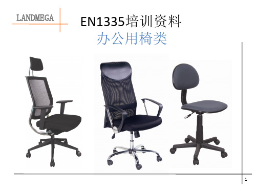
en1335-1-2-3办公家具-办公椅测试方法(中文说明)
最小
最大
允许 (+)
靠背衬垫的高度 否 220 + 是 否 220 + 是
++
高度可调节的
高度不可调节的 否 260 + 是 否 260 + 是 否 260 + 是
12
LANDMEGA
EN1335-1: 尺寸测定
5.7坐垫表面到靠背上边缘的高度h的测量 A类:h≥360mm B类: h≥360mm C类: h≥360mm
B
320
80000
3 J-E T
120
循环
E
320
20000
4 F-H F
1200 循环
H
320
20000
5 D-G D
1100 循环
G
1100 20000
38
LANDMEGA EN1335-3: 安全测试方法
9.4扶手测试
加载400N,测试60000次; 静压750N,每次1分钟,
重复5次; 静压900N,每次1分钟,
不可调节
否
200
250
否
可调节
是
200
250
是
19
LANDMEGA EN1335-1: 尺寸测定
5.13扶手有用的前端到座位前端的距离q的 测量
A类:q≥100mm B类:q≥100mm C类:q≥100mm
20
LANDMEGA EN1335-1: 尺寸测定
5.13扶手内宽r的测量 A类:460≤ r ≤ 510mm B类:460 ≤ r ≤ 510mm C类:r≥460mm
3
LANDMEGA EN1335标准内容
高阻尼橡胶支座的尺寸
高阻尼橡胶隔震支座一、概述在天然橡胶中加入各种配合剂,可以提高橡胶的阻尼性能,利用这种具有阻尼效果的橡胶制成的支座称为高阻尼橡胶隔震支座(HDR支座)。
高阻尼橡胶隔震,由于采用高阻尼橡胶,具有稳定支承、弹性复位和阻尼功能,在地震中可以吸收地震能量,减轻地震影响,并可单独作为隔震装置使用。
HDR 系列高阻尼隔震橡胶支座是按照国家标准(GB20688),同时参考欧洲标准进行设计,在借鉴国外先进技术的同时,充分考虑了中国国情,对结构和材料进行了优化设计,隔震性能好,适用范围广,是一款性价比较高的新型桥梁构件产品。
该产品分为矩形固定型、矩形滑动型、圆形固定型、圆形滑动型四种类型,适用于8 度及8 度以下地震区各类公路及市政桥梁。
二、HDR主要特点:1.竖向承载能力:具有较高的强度和竖向刚度,能够承受较大的竖向荷载2.水平变形能力HDR 支座除具备较强的水平变形能力外,对水平变形还有一定抵抗作用,这种抵抗作用可吸收地震能量。
3.可复位性地震发生时,支座在外力作用下产生一定变形,吸收地震能量;地震发生后,支座通过橡胶的恢复力回到初始位置。
4.耐久性设计使用寿命可达60年。
5.无污染因不使用铅芯,减少了铅污染三设计依据. 《公路桥涵设计通用规范》(JTG D60-2004). 《公路钢筋混凝土及预应力混凝土桥涵设计规范》(JTG D62-2004). 《公路桥梁抗震设计细则》(JTG/T B02-01-2008). 《城市桥梁设计细则》(CJJ11-93). 《橡胶支座:隔震橡胶支座试验方法》(GB/T 20688.1-2007). 《橡胶支座:桥梁隔震橡胶支座》(GB 20688.2-2006). 《Structural bearings 》滑动元件部分(EN 1337-2:2005). 《Structural bearings 》橡胶支座部分(EN 1337-3:2005)四技术性能4.1 支座规格圆形分为35 类:D150,D175,D200,D225,D250,D275,D300,D325,D350,D375,D400,D425,D450,D475,D500,D550,D600,D650,D700,D750,D800,D850,D900,D950,D1000,D1050,D1100,D1150,D1200,D1250,D1300,D1350,D1400,D1450,D1500;矩形分为62 类:200×200,200×250,200×300,250×250,250×300,250×350,300×300,300×350,300×400,300×450,350×350,350×400,350×450,350×500,400×400,400×450,400×500,400×550,400×600,450×450,450×500,450×550,450×600,450×650,500×500,500×550,500×600,500×650,500×700,550×550,550×600,550×650,600×600,600×650,600×700,600×750,650×650,650×700,650×750,650×800,700×700,700×750,700×800,700×850,750×750,750×800,750×850,750×900,800×800,800×850,800×900,800×950,850×850,850×900,850×950,850×1000,900×900,900×950,900×1000,950×950,950×1000,1000×1000 。
EN 结构支座一般设计规则全中文版

欧洲标准(EN 1337-1: 2000)第1部分:一般设计规则第4页EN 1337-1: 20001、范围本标准适用于结构支座,不管是在桥梁或者其它结构中。
本标准未包含:a)主要以传递力矩作用的支座b)承受向上作用力的支座c)用于可移动桥梁的支座d)混凝土铰链e)地震装置尽管本标准不是用于规范临时支座,但可以作为一个指导。
(临时支座是指用于结构维修或养护时使用的支座)注1:尽管本标准的说明是必须的,但是对于所有结构设计以及地质方面影响的考虑本身并不是足够的。
prEN1337‐2至prEN1337‐8是相关支座的要求,这些说明只限于一定温度范围内使用。
2、规范性引用文件本标准包含其它已发行的带有日期或者没有日期标注的标准。
引用的标准清单如下。
对于有日期标注的引用,只使用已引用 的版本。
对于没有日期标注的引用,使用最新版本的引用文件(包括所有修订部分)。
prEN 1337‐2 结构支座…第2部分:滑动元件prEN 1337‐3 结构支座…第3部分:弹性支座prEN 1337‐4 结构支座…第4部分:滚柱支座prEN 1337‐5 结构支座…第5部分:盆式支座prEN 1337‐6 结构支座…第6部分:摇杆支座prEN 1337‐7 结构支座…第7部分:球面和柱面PTFE支座prEN 1337‐8 结构支座…第8部分:导向支座和止推支座prEN 1337‐9 :1997 结构支座…第9部分:防护prEN 1337‐10 结构支座…第10部分:检验和维护prEN 1337‐11 :1997 结构支座…第11部分:运输、储存和安装ENV1991‐1: 1994 欧标1:结构设计基础…第1部分:设计基础ENV1992‐2: 1996 欧标2:混泥土结构设计…第2部分:混泥土桥梁ENV1993‐2: 1997 欧标3:钢结构设计…第2部分:钢制桥梁ENV1994‐2: 1997 欧标4:钢与混泥土混合结构设计…第2部分:混合桥梁第5页EN 1337-1: 20003、术语、定义、符号和缩写3.1、术语和定义在应用本标准时,使用以下术语和定义:极限许用条件(ULS)与工作许用条件(SLS)的定义与ENV1991‐1中定义的一致。
橡胶缓冲块执行标准

橡胶缓冲块执行标准
橡胶缓冲块通常用于减震、缓冲和隔振,适用于各种工程和交通领域。
以下是一些可能涉及橡胶缓冲块的执行标准:
1. GB/T 3221-2008《橡胶振动隔离器技术条件》:
* 该中国国家标准规定了橡胶振动隔离器的技术要求,包括了橡胶缓冲块的性能、试验方法、检验规则等。
2. EN 1337-3:2018《结构用橡胶材料. 第3部分: 橡胶隔震装置性能的规范》:
* 该欧洲标准规定了结构用橡胶材料,包括橡胶缓冲块,的性能要求和试验方法。
3. AASHTO (American Association of State Highway and Transportation Officials):
* AASHTO可能发布了一些与橡胶缓冲块在交通领域使用相关的标准。
例如,AASHTO LRFD Bridge Design Specifications 中可能包含了有关橡胶缓冲块的规定。
4. BS EN 1337-2:2003《建筑结构. 结构用橡胶材料. 第2部分:性能要求和试验方法》:
* 该英国标准规定了建筑结构中使用的橡胶材料的性能要求和试验方法,也可能适用于橡胶缓冲块。
在选择和使用橡胶缓冲块时,建议参考相应的国家或地区标准以确保其性能符合项目要求和安全标准。
此外,制造商通常也提供有关其产品符合的标准和规范的信息。
- 1、下载文档前请自行甄别文档内容的完整性,平台不提供额外的编辑、内容补充、找答案等附加服务。
- 2、"仅部分预览"的文档,不可在线预览部分如存在完整性等问题,可反馈申请退款(可完整预览的文档不适用该条件!)。
- 3、如文档侵犯您的权益,请联系客服反馈,我们会尽快为您处理(人工客服工作时间:9:00-18:30)。
EN 1337-22004年3月ICS 91.010.30 取代:EN 1337-2:2000结构支座第2部分: 滑动元件本欧洲标准于2004年6月由CEN通过。
CEN的委员需遵守CEN/CENELEC 的内部规章,并约定本欧洲标准为国际性标准之条件,且不需作任何修改。
本欧洲标准的草案由CEN建立并发行三个官方版本(英文、法文、德文)。
CEN 委员为国际标准个体所组成,包括奥地利、比利时、塞浦路斯、丹麦、捷克、爱沙尼亚、匈牙利、芬兰、法国、德国、希腊、冰岛、爱尔兰、意大利、拉托维亚、立陶宛、卢森堡、马耳他、荷兰、挪威、波兰葡萄牙、斯洛伐克、斯洛文尼亚、西班牙、瑞典、瑞士及联合王国目录前言说明1 范围2 标准的参考文献3 术语,定义,符号和缩写词4 性能要求5 材料6 设计要求7 制造装配和公差8 设计的达标评估9 安装10 使用过程中的检测的重点附录 A (增进了解篇) 简化的滑动元件附录 B (增进了解篇) PTFE板凹孔的摩擦系数附录 C (增进了解篇) 安装在混凝土上的锚锭板形变的计算方法附录 D (规范篇) 摩擦力的测试方法附录 E (规范篇) 锚锭板表面的铬硬度-孔隙度试剂试验附录 F (规范篇) 电镀表面厚度测定附录G (规范篇) 润滑油的油剂单独试验附录H (规范篇) 润滑油的氧化稳定性附录J (规范篇) 不锈钢附着板–实验室剪切力测试附录K (规范篇) 工厂生产管理(FPC)附录L (增进了解篇) 检验测试参考书目前言此文献(EN 1337-2:2004)由CEN/TC167盆式支座技术委员会制定,其秘书工作由UNI承担。
此文献(EN 1337-2:2004)取代EN 1337-2:2000。
此欧洲标准EN 1337包括以下11个部分:第一篇一般设计通则第二篇滑动元件第三篇橡胶支座第四篇滚轴支座第五篇盆式支座第六篇摇轴支座第七篇球型和圆柱型PTFE 支座第八篇导向型支座和固定支座第九篇保护第十篇检查和保养第十一篇运输,储存和安装附录A, B, C 和L是增进了解篇附录D, E, F, G, H, J 和K是规范篇。
据CEN/CENELEC的内部规则,以下国家在贯彻此标准的范围之内:奥地利,比利时,捷克,丹麦,芬兰,法国,德国,希腊,冰岛,爱尔兰,意大利,卢森堡,马耳他,荷兰,挪威,葡萄牙,西班牙,瑞典,瑞士及联合王国。
说明此标准建议的最低使用温度为-35oC。
未来修改建议延伸到-40oC。
此标准未含超越条款1列出温度需要特别考虑的使用范围,此标准未提供相应的性能和要求。
1 范围此欧洲标准指定了滑动元件的设计和制造性能及指定了非结构支座但是结构支座元件唯一的零件在此标准相关部分的定义。
合适的组件在EN 1337-1:2000表格1中列出。
滑动面附着单个或多个PTFE板外接圆的直径小于75mm或大于1500mm,以及使用温度低于-35oC或高于48oC的情况在此标准范围之外。
滑动元件在制造过程中作为临时装置使用,例如在上部结构建造时,也在此标准范围之外。
此标准也指定了曲面滑动面(不是单独支座的零件而是和球型和圆柱型PTFE支座结合)的规定:per EN1337。
注:此欧洲标准的一般原则规定可使用在超出范围的滑动元件上,但其的延伸适应性应验证。
2 标准的参考资料以下的参考资料是使用本标准时必不可少的。
标注日期的参考资料仅在此提到的适用。
无标注日期的参考资料仅最新的版本(包括所有的改动)适用。
EN 1337-1:2000,结构支座——第1部分:一般设计原则EN 1337-7, 结构支座——第七部分: 球型和圆柱型PTFE支座EN 1337-10,2003,结构支座——第10部分:检测和维护EN 1337-11:1997, 结构支座——第11部分: 运输,储存和安装EN 10025, 结构钢的热轧产品–技术交货条件EN 10088-2,不锈钢—第2部分:一般用途的片、盘、条的技术交货条件EN 10113-1,可焊细粒结构钢热轧产品-第1部分:一般技术交货条件EN 10137-1,1996, 调质或沉淀硬化状态下高屈服点结构钢制薄板和宽扁钢–第1部分:一般技术交货条件EN 10204,金属产品—检测文献的种类ENV 1992-1-1, 欧洲规程2:混凝土结构设计.建筑概要ENV 1993-1-1, 欧洲规程23:不锈钢结构设计.建筑概要EN ISO 527-1, 塑料-拉伸性能的测定第一部分(ISO 527-1:1993 包含修正案1:1994)EN ISO 527-3, 塑料-拉伸性能的测定第三部分:薄膜和片材的试验条件(ISO527-3:1995)EN ISO 1183, (所有部分), 塑料-非泡沫塑料密度和相对密度的测定方法EN ISO 2039-1, 塑料硬度测定.第1部分:压球法(ISO 2039-1:2001)EN ISO 2409, 色漆和清漆.交叉切割试验(ISO 2409:1992)EN ISO 4287, 产品几何量技术规范(GPS) 表面结构:轮廓法表面结构的术语、定义及参数技术勘误(ISO 4287:1997)EN ISO 6506, (所有部分), 金属材料.布氏硬度试验EN ISO 6507-1, 金属材料,维氏硬度试验第1部分:试验的方法(ISO 6507-1:1997)EN ISO 6507-2, 金属材料,维氏硬度试验第2部分:试验仪器试验(ISO 6507-2:1997)ISO 1083,球墨铸钢-分级ISO 2137, 石油产品润滑脂和石油脂锥入度的测定ISO 2176, 石油产品.润滑脂.滴点的测定ISO 3016, 石油产品.滴点的测定ISO 3522, 铸造铝合金化学成分和力学性能ISO 3755,一般设计用途的碳铸钢prEN ISO 6158, 金属镀层,工程技术用铬电镀层(ISO/DIS 6158:2002)3 术语,定义,符号和缩写词3.1 术语,定义本标准提供以下术语和定义3.1.1基板支承滑动材料的金属组件3.1.2摩擦力因数侧向力(阻力F x)转化成法向力F2的比例3.1.3复合材料用来导向的滑动材料3.1.4导向限制滑动支座在横向或纵向上位移的滑动元件3.1.5硬铬表面不锈钢基件的电镀硬铬层3.1.6润滑油特殊的油脂,作用是减小橡胶垫与金属部件间的摩擦,从而减少磨损,降低产品的转动刚度。
3.1.7配合面配合PTFE或复合材料滑动的坚硬光滑的金属面3.1.8聚四氟乙烯(PTFE)一种低摩擦力因数的热塑塑料材料3.1.9滑动面一对平面或曲面的材料允许相对位移的组件3.1.10滑动材料构成滑动面的材料3.2 符号本标准提供以下符号:3.2.1 大写拉丁字母A 滑动面的接触面积........................................................... mm2E 弹性模量......................................................................... GPaF 作用力............................................................................... N; kNG 永久作用........................................................................... N; kNL 单个或多个PTFE板的外接圆直径(见图3, 4和5);导向PTFE或复合材料板的长度(见图6) ………………................... mmM 弯矩................................................................................... N x mm; kN x m N 沿法向到支座主要面的力............................................. N; kNR y5i表面平均粗糙度..............................................................mS 形状因数T 温度................................................................................o CV 横向力或剪切力........................................................... N; kN3.2.2 小写拉丁字母a PTFE板的最小尺寸; ...................................................... mm长方形板的较小边........................................................ mmb 长方形板的较大边........................................................... mmc 滑动组件间的距离(卡榫和卡榫孔的宽度差) ............... mmd 直径,对角线.................................................................... mme 偏心距............................................................................... mmf 公制压力强度................................................................. MPah PTFE板凹孔深度............................................................. mmn 周期数s 滑动距离......................................................................... mmt 厚度,时间........................................................................ mm; s; hu PTFE板周长................................................................... mmv 滑动速度........................................................................... mm/sw 形变x 纵向轴y 横向轴z 通常到支座主要面的轴向3.2.3 希腊字母α角度................................................................................. radγ局部安全因数δ断裂拉伸率..................................................................... %△z 平面或曲面滑动面与理论表面的最大.......................... mmλ比率, 因数μ摩擦力因数μ1 初始摩擦力因数; 例如开始或重启任何试验的第一次位移时产生的最大摩擦力因数μT 指定温度状态的最大摩擦力因数ρ质量密度......................................................................... kg/m3σ通常压力......................................................................... MPa3.2.4 下标a 平均b 基板c 混凝土CM 复合材料d 设计dyn 动态的G 永久作用g 几何的k 特性M 材料max 最大min 最小n 周期数p PTFE聚四氟乙烯pl 预载荷Q 可变作用R 阻力r 简化S 作用产生的内力和内力矩s 静态的t 张力T 温度u 极限x, y, z 座标3.3 缩写CM 复合材料PTFE 聚四氟乙烯NDP 国家规定参数4 性能要求注滑动和导向元件允许在平面或曲面滑动面上有最小摩擦力的位移. 要求摩擦阻力的具体确认,因为单独的机械和物理特性的确认不能充分保证这些组件将有必需的性能. 如符合附录D规定的材料组件样品满足附录D规定的确认摩擦力使用条款的要求,滑动和导向元件的性能视为合格。
