1.5KE440A
1.5KE100CA参数资料
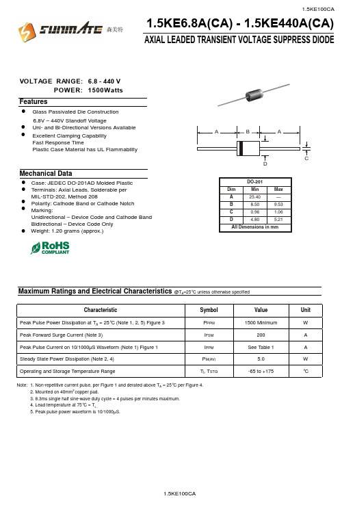
POWER: 1500Wa t VOLTAGE RANGE: 6.8 - 440 VAXIAL LEADED TRANSIENT VOLTAGE SUPPRESS DIODE1.5KE6.8A(CA) - 1.5KE440A(CA)6.8V – 440V Standoff VoltageCase: JEDEC DO-201AD Molded Plastic FeaturesGlass Passivated Die Construction Uni- and Bi-Directional Versions Available Excellent Clamping Capability Fast Response TimePlastic Case Material has UL FlammabilityMechanical DataTerminals: Axial Leads, Solderable per MIL-STD-202, Method 208 Polarity: Cathode Band or Cathode Notch Marking:Unidirectional – Device Code and Cathode Band Bidirectional – Device Code OnlyMaximum Ratings and Electrical Characteristics@T A =25°C unless otherwise specifiedCharacteristicSymbol Value Unit Peak Pulse Power Dissipation at T A = 25°C (Note 1, 2, 5) Figure 3P PPM 1500 MinimumW Peak Forward Surge Current (Note 3)I FSM 200A Peak Pulse Current on 10/1000µS Waveform (Note 1) Figure 1I PPM See Table 1A Steady State Power Dissipation (Note 2, 4)P M(AV) 5.0W Operating and Storage Temperature RangeT j , T STG-65 to +175°CNote: 1. Non-repetitive current pulse, per Figure 1 and derated above T A = 25°C per Figure 4.2. Mounted on 40mm 2 copper pad.3. 8.3ms single half sine-wave duty cycle = 4 pulses per minutes maximum.4. Lead temperature at 75°C = T L .5. Peak pulse power waveform is 10/1000µS.!!!!!!!Weight: 1.20 grams (approx.)!森美特94.085.57.0211.4510.513.4 1.5KE440CA1.5KE400CA 1.5KE350A 1.5KE220CA 1.5KE170CA 1.5KE150A 1.5KE82CA (uA)R RMW RMW@V leakage Reverse CurrentPulse Peak (A)Vc(V)(mA)BR MAX CurrentMax.BR MIN @I Min.Volgtage Breakdown (V)(BI)(Uni)Voltage Stand-Off Reverse Maximum Clamping V T PP(V)V @I Volgtage Breakdown Test (V)V T Volgtage @I PP 1.5KE62CA 1.5KE56CA 1.5KE51CA 1.5KE47CA 1.5KE43CA 1.5KE39CA 1.5KE36CA 1.5KE33CA 1.5KE30CA 1.5KE27CA 1.5KE24CA 1.5KE22CA 1.5KE20CA 1.5KE18CA 1.5KE16CA 1.5KE15CA 1.5KE13CA 1.5KE12CA 1.5KE11CA 1.5KE10CA 1.5KE9.1CA 1.5KE8.2CA 1.5KE7.5CA 1.5KE6.8CA 1.5KE6.8A 1.5KE7.5A 1.5KE8.2A 1.5KE9.1A 1.5KE10A 1.5KE11A 1.5KE12A 1.5KE13A 1.5KE15A 1.5KE16A 1.5KE18A 1.5KE20A 1.5KE22A 1.5KE24A 1.5KE27A 1.5KE30A 1.5KE33A1.5KE36A 1.5KE39A 1.5KE43A 1.5KE47A 1.5KE51A 1.5KE56A 1.5KE300CA 1.5KE250CA 1.5KE200CA 1.5KE180CA 1.5KE160CA 1.5KE150CA 1.5KE130CA 1.5KE120CA 1.5KE110CA 1.5KE100CA 1.5KE91CA 1.5KE75CA 1.5KE68CA 1.5KE62A 1.5KE68A 1.5KE75A 1.5KE82A 1.5KE91A 1.5KE100A 1.5KE110A 1.5KE120A 1.5KE130A 1.5KE160A 1.5KE170A 1.5KE180A 1.5KE200A 1.5KE220A 1.5KE250A 1.5KE300A 1.5KE400A 1.5KE440A1.5KE350CA 5.80 6.45 7.14 10 144.8 1000.06.407.13 7.88 10 11.3 134.5 500.0 7.79 8.61 10 12.1 125.6 200.0 7.78 8.65 9.55 1.0 113.4 50.0 8.55 9.50 10.5 1.0 14.5 104.8 10.0 9.40 10.11.6 1.0 15.6 97.4 5.0 10.212.6 1.0 16.7 91.0 5.011.1 12.4 13.7 1.0 18.2 83.5 5.0 12.8 14.3 15.8 1.0 21.2 71.75.013.615.2 16.8 1.0 22.5 67.6 5.0 15.3 17.1 18.9 1.0 25.2 60.3 5.0 17.1 19.0 21.0 1.0 27.7 54.9 5.0 18.820.923.1 1.0 30.6 49.7 5.020.5 22.8 25.2 1.0 33.2 45.8 5.023.1 25.7 28.4 1.0 37.5 40.5 5.0 25.6 28.5 31.5 1.0 41.4 36.7 5.0 28.2 31.4 34.7 1.0 45.7 33.3 5.030.8 34.2 37.8 1.0 49.9 30.5 5.033.3 37.1 41.0 1.0 53.9 28.2 5.0 36.8 40.9 45.2 1.0 59.3 25.6 5.0 40.2 44.7 49.4 1.0 64.8 23.5 5.0 43.648.553.6 1.0 70.1 21.7 5.047.8 53.2 58.8 1.0 77.0 19.7 5.053.0 58.9 65.1 1.0 85.0 17.9 5.058.1 64.6 71.4 1.0 92.0 16.5 5.0 64.1 71.3 78.8 1.0 103 14.8 5.0 70.1 77.9 86.1 1.0 113 13.5 5.0 77.8 86.5 95.5 1.0 125 12.2 5.095.0 105 1.0 137 11.1 5.0105 116 1.0 152 10.0 5.0102 114 126 1.0 165 9.2 5.0 111 124 137 1.0 179 8.5 5.0128 143 158 1.0 207 7.3 5.0136 152 168 1.0 219 6.9 5.0 145 162 179 1.0 234 6.5 5.0 154 171 189 1.0 246 6.2 5.0 171 190 210 1.0 274 5.5 5.0 185 209 231 1.0 328 4.6 5.0 214 237 263 1.0 344 4.4 5.0256 285 315 1.0 414 3.7 5.0300 333 368 1.0 482 3.2 5.0 342 380 420 1.0 548 2.8 5.0 376 418 462 1.0 600 2.5 5.0TYPE森美特255075100125150175200100755025T ,AMBIENT TEMPERATURE (°C)Fig.4Pulse Derating CurveA P K P U L S E D E R A T I N G (%P K P W R O R C U R R E N T )25507510012515017520002.55.0T ,LEAD TEMPERATURE (°C)Fig.5,Steady State Power DeratingLP ,S T E A D Y S T A T E P O W E R D I S S I P A T I O N (W )d 0.11.0T ,PULSE WIDTH (µs)Fig.3Pulse Rating Curvep 0.1101001.010100100010000P ,P E A K P U L S E P O W E R (k W )P0123I ,P E A K P U L S E C U R R E N T (%)P p pt,TIME (ms)Fig.1Pulse Waveform110100100010100100010,000V ,REVERSE STANDOFF VOLTAGE (V)Fig.2Typical Junction CapacitanceRWM C ,C A P A C I T A N C E (p F )j 森美特。
1.5KE20A参数资料
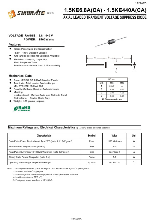
POWER: 1500Wa t VOLTAGE RANGE: 6.8 - 440 VAXIAL LEADED TRANSIENT VOLTAGE SUPPRESS DIODE1.5KE6.8A(CA) - 1.5KE440A(CA)6.8V – 440V Standoff VoltageCase: JEDEC DO-201AD Molded Plastic FeaturesGlass Passivated Die Construction Uni- and Bi-Directional Versions Available Excellent Clamping Capability Fast Response TimePlastic Case Material has UL FlammabilityMechanical DataTerminals: Axial Leads, Solderable per MIL-STD-202, Method 208 Polarity: Cathode Band or Cathode Notch Marking:Unidirectional – Device Code and Cathode Band Bidirectional – Device Code OnlyMaximum Ratings and Electrical Characteristics@T A =25°C unless otherwise specifiedCharacteristicSymbol Value Unit Peak Pulse Power Dissipation at T A = 25°C (Note 1, 2, 5) Figure 3P PPM 1500 MinimumW Peak Forward Surge Current (Note 3)I FSM 200A Peak Pulse Current on 10/1000µS Waveform (Note 1) Figure 1I PPM See Table 1A Steady State Power Dissipation (Note 2, 4)P M(AV) 5.0W Operating and Storage Temperature RangeT j , T STG-65 to +175°CNote: 1. Non-repetitive current pulse, per Figure 1 and derated above T A = 25°C per Figure 4.2. Mounted on 40mm 2 copper pad.3. 8.3ms single half sine-wave duty cycle = 4 pulses per minutes maximum.4. Lead temperature at 75°C = T L .5. Peak pulse power waveform is 10/1000µS.!!!!!!!Weight: 1.20 grams (approx.)!森美特94.085.57.0211.4510.513.4 1.5KE440CA1.5KE400CA 1.5KE350A 1.5KE220CA 1.5KE170CA 1.5KE150A 1.5KE82CA (uA)R RMW RMW@V leakage Reverse CurrentPulse Peak (A)Vc(V)(mA)BR MAX CurrentMax.BR MIN @I Min.Volgtage Breakdown (V)(BI)(Uni)Voltage Stand-Off Reverse Maximum Clamping V T PP(V)V @I Volgtage Breakdown Test (V)V T Volgtage @I PP 1.5KE62CA 1.5KE56CA 1.5KE51CA 1.5KE47CA 1.5KE43CA 1.5KE39CA 1.5KE36CA 1.5KE33CA 1.5KE30CA 1.5KE27CA 1.5KE24CA 1.5KE22CA 1.5KE20CA 1.5KE18CA 1.5KE16CA 1.5KE15CA 1.5KE13CA 1.5KE12CA 1.5KE11CA 1.5KE10CA 1.5KE9.1CA 1.5KE8.2CA 1.5KE7.5CA 1.5KE6.8CA 1.5KE6.8A 1.5KE7.5A 1.5KE8.2A 1.5KE9.1A 1.5KE10A 1.5KE11A 1.5KE12A 1.5KE13A 1.5KE15A 1.5KE16A 1.5KE18A 1.5KE20A 1.5KE22A 1.5KE24A 1.5KE27A 1.5KE30A 1.5KE33A1.5KE36A 1.5KE39A 1.5KE43A 1.5KE47A 1.5KE51A 1.5KE56A 1.5KE300CA 1.5KE250CA 1.5KE200CA 1.5KE180CA 1.5KE160CA 1.5KE150CA 1.5KE130CA 1.5KE120CA 1.5KE110CA 1.5KE100CA 1.5KE91CA 1.5KE75CA 1.5KE68CA 1.5KE62A 1.5KE68A 1.5KE75A 1.5KE82A 1.5KE91A 1.5KE100A 1.5KE110A 1.5KE120A 1.5KE130A 1.5KE160A 1.5KE170A 1.5KE180A 1.5KE200A 1.5KE220A 1.5KE250A 1.5KE300A 1.5KE400A 1.5KE440A1.5KE350CA 5.80 6.45 7.14 10 144.8 1000.06.407.13 7.88 10 11.3 134.5 500.0 7.79 8.61 10 12.1 125.6 200.0 7.78 8.65 9.55 1.0 113.4 50.0 8.55 9.50 10.5 1.0 14.5 104.8 10.0 9.40 10.11.6 1.0 15.6 97.4 5.0 10.212.6 1.0 16.7 91.0 5.011.1 12.4 13.7 1.0 18.2 83.5 5.0 12.8 14.3 15.8 1.0 21.2 71.75.013.615.2 16.8 1.0 22.5 67.6 5.0 15.3 17.1 18.9 1.0 25.2 60.3 5.0 17.1 19.0 21.0 1.0 27.7 54.9 5.0 18.820.923.1 1.0 30.6 49.7 5.020.5 22.8 25.2 1.0 33.2 45.8 5.023.1 25.7 28.4 1.0 37.5 40.5 5.0 25.6 28.5 31.5 1.0 41.4 36.7 5.0 28.2 31.4 34.7 1.0 45.7 33.3 5.030.8 34.2 37.8 1.0 49.9 30.5 5.033.3 37.1 41.0 1.0 53.9 28.2 5.0 36.8 40.9 45.2 1.0 59.3 25.6 5.0 40.2 44.7 49.4 1.0 64.8 23.5 5.0 43.648.553.6 1.0 70.1 21.7 5.047.8 53.2 58.8 1.0 77.0 19.7 5.053.0 58.9 65.1 1.0 85.0 17.9 5.058.1 64.6 71.4 1.0 92.0 16.5 5.0 64.1 71.3 78.8 1.0 103 14.8 5.0 70.1 77.9 86.1 1.0 113 13.5 5.0 77.8 86.5 95.5 1.0 125 12.2 5.095.0 105 1.0 137 11.1 5.0105 116 1.0 152 10.0 5.0102 114 126 1.0 165 9.2 5.0 111 124 137 1.0 179 8.5 5.0128 143 158 1.0 207 7.3 5.0136 152 168 1.0 219 6.9 5.0 145 162 179 1.0 234 6.5 5.0 154 171 189 1.0 246 6.2 5.0 171 190 210 1.0 274 5.5 5.0 185 209 231 1.0 328 4.6 5.0 214 237 263 1.0 344 4.4 5.0256 285 315 1.0 414 3.7 5.0300 333 368 1.0 482 3.2 5.0 342 380 420 1.0 548 2.8 5.0 376 418 462 1.0 600 2.5 5.0TYPE森美特255075100125150175200100755025T ,AMBIENT TEMPERATURE (°C)Fig.4Pulse Derating CurveA P K P U L S E D E R A T I N G (%P K P W R O R C U R R E N T )25507510012515017520002.55.0T ,LEAD TEMPERATURE (°C)Fig.5,Steady State Power DeratingLP ,S T E A D Y S T A T E P O W E R D I S S I P A T I O N (W )d 0.11.0T ,PULSE WIDTH (µs)Fig.3Pulse Rating Curvep 0.1101001.010100100010000P ,P E A K P U L S E P O W E R (k W )P0123I ,P E A K P U L S E C U R R E N T (%)P p pt,TIME (ms)Fig.1Pulse Waveform110100100010100100010,000V ,REVERSE STANDOFF VOLTAGE (V)Fig.2Typical Junction CapacitanceRWM C ,C A P A C I T A N C E (p F )j 森美特。
瞬态抑制二极管1.5KE型号参数规格书大全

Axial Lead Transient Voltage Suppressors (TVS)The 1.5KE series is designedspecifically to protect sensitive electronicequipment from voltage transients induced by lightning and other transientvoltage events.Uni-directional Bi-directionalu Glass passivated chip junction in DO-201 Packageu Low leakageu Uni and Bidirectional unitu Excellent clamping capabilityu1500W Peak power capability at 10 × 1000µs waveform Repetitionrate (duty cycle):0.01%u Fast response time: typically less than 1.0ps from 0 Volts to V BR minu Typical I R less than 5μA above 12V.u High Temperature soldering: 260°C/40 seconds at terminalsu Typical maximum temperature coefficient ΔV BR = 0.1% ×V BR@25°C×ΔTu Plastic package has Underwriters Laboratory Flammability 94V-0u Matte tin lead–free Platedu Halogen free and RoHS compliantu Typical failure mode is short from over-specified voltage or currentu Whisker test is conducted based on JEDEC JESD201A per its table4a and 4cu IEC-61000-4-2 ESD 15kV(Air), 8kV (Contact)u ESD protection of data lines in accordance with IEC 61000-4-2(IEC801-2)u EFT protection of data lines in accordance with IEC 61000-4-4(IEC801-4)TVS devices are ideal for the protection of I/O interfaces, V bus and othervulnerable circuits used in Telecom, Computer, Industrial and Consumerelectronic applications.Parameter Symbol Value Unit Peak Pulse Power Dissipation with a 10/1000µs waveform (Fig.1)(Note1), (Note 2)P PPM1500 Watts Peak Pulse Current with a 10/1000µs waveform.(Note1,Fig.3) I PP See Next Table Amps Power Dissipation on Infinite Heat Sink at T L=75°C P M(AV) 6.5 Watt Peak Forward Surge Current, 8.3ms Single Half Sine Wave (Note 3) I FSM200 Amps Maximum Instantaneous Forward Voltage at 25A for Unidirectional Only(Note 4)V F 3.5/5.0 Voltage Operating junction and Storage Temperature Range. T J , T STG-55 to +150 °C Notes:1. Non-repetitive current pulse, per Fig. 3 and derated above T A = 25°C per Fig.2.2. Mounted on 5.0mm x 5.0mm (0.03mm thick) Copper Pads to each terminal.3. 8.3ms single half sine-wave, or equivalent square wave, Duty cycle = 4 pulses per minutes maximum.4. V F < 3.5V for V BR < 200V and V F< 6.5V for V BR > 201V.AAxial Lead Transient Voltage Suppressors (TVS)Part NumberBreakdown Voltage V BR(V)@I T Uni Bi Reverse Stand-Off Voltage V RWM (V) MIN MAX Test Current I T (mA) Maximum Clamping Voltage V C @I PP (V) Maximum Peak Pulse Current I PP (A) Maximum Reverse Leakage I R @V RWM (μA)1.5KE6.8 1.5KE6.8C 5.5 6.12 7.48 10 10.8 138.89 1000 1.5KE6.8A 1.5KE6.8CA 5.8 6.46 7.14 10 10.5 142.86 1000 1.5KE7.5 1.5KE7.5C 6.1 6.75 8.25 10 11.7 128.21 500 1.5KE7.5A 1.5KE7.5CA 6.4 7.13 7.88 10 11.3 132.74 500 1.5KE8.2 1.5KE8.2C 6.6 7.38 9.02 10 12.5 120.00 200 1.5KE8.2A 1.5KE8.2CA 7.0 7.79 8.61 10 12.1 123.97 200 1.5KE9.1 1.5KE9.1C 7.4 8.19 10.01 1 13.8 108.70 50 1.5KE9.1A 1.5KE9.1CA 7.8 8.65 9.56 1 13.4 111.94 50 1.5KE10 1.5KE10C 8.1 9.00 11.00 1 15.0 100.00 10 1.5KE10A 1.5KE10CA 8.6 9.50 10.50 1 14.5 103.45 10 1.5KE11 1.5KE11C 8.9 9.90 12.10 1 16.2 92.59 5 1.5KE11A 1.5KE11CA 9.4 10.45 11.55 1 15.6 96.15 5 1.5KE12 1.5KE12C 9.7 10.80 13.20 1 17.3 86.71 5 1.5KE12A 1.5KE12CA 10.2 11.40 12.60 1 16.7 89.82 5 1.5KE13 1.5KE13C 10.5 11.70 14.30 1 19.0 78.95 5 1.5KE13A 1.5KE13CA 11.1 12.35 13.65 1 18.2 82.42 5 1.5KE15 1.5KE15C 12.1 13.50 16.50 1 22.0 68.18 5 1.5KE15A 1.5KE15CA 12.8 14.25 15.75 1 21.2 70.75 5 1.5KE16 1.5KE16C 12.9 14.40 17.60 1 23.5 63.83 5 1.5KE16A 1.5KE16CA 13.6 15.20 16.80 1 22.5 66.67 5 1.5KE18 1.5KE18C 14.5 16.20 19.80 1 26.5 56.60 5 1.5KE18A 1.5KE18CA 15.3 17.10 18.90 1 25.2 59.52 5 1.5KE20 1.5KE20C 16.2 18.00 22.00 1 29.1 51.55 5 1.5KE20A 1.5KE20CA 17.1 19.00 21.00 1 27.7 54.15 5 1.5KE22 1.5KE22C 17.8 19.80 24.20 1 31.9 47.02 5 1.5KE22A 1.5KE22CA 18.8 20.90 23.10 1 30.6 49.02 5 1.5KE24 1.5KE24C 19.4 21.60 26.40 1 34.7 43.23 5 1.5KE24A 1.5KE24CA 20.5 22.80 25.20 1 33.2 45.18 5 1.5KE27 1.5KE27C 21.8 24.30 29.70 1 39.1 38.36 5 1.5KE27A 1.5KE27CA 23.1 25.65 28.35 1 37.5 40.00 5 1.5KE30 1.5KE30C 24.3 27.00 33.00 1 43.5 34.48 5 1.5KE30A 1.5KE30CA 25.6 28.50 31.50 1 41.4 36.23 5 1.5KE33 1.5KE33C 26.8 29.70 36.30 1 47.7 31.45 5 1.5KE33A 1.5KE33CA 28.2 31.35 34.65 1 45.7 32.82 5 1.5KE36 1.5KE36C 29.1 32.40 39.60 1 52.0 28.85 5 1.5KE36A 1.5KE36CA 30.8 34.20 37.80 1 49.9 30.06 5 1.5KE39 1.5KE39C 31.6 35.10 42.90 1 56.4 36.60 5 1.5KE39A 1.5KE39CA 33.3 37.05 40.95 1 53.9 27.83 5 1.5KE43 1.5KE43C 34.8 38.70 47.30 1 61.9 24.23 5 1.5KE43A 1.5KE43CA 36.8 40.85 45.15 1 59.3 25.30 5 1.5KE47 1.5KE47C 38.1 42.30 51.70 1 67.8 22.12 5 1.5KE47A 1.5KE47CA 40.2 44.65 49.35 1 64.8 23.15 5 1.5KE51 1.5KE51C 41.3 45.90 56.10 1 73.5 20.41 5 1.5KE51A 1.5KE51CA 43.6 48.45 53.55 1 70.1 21.40 5 1.5KE56 1.5KE56C 45.4 50.40 61.60 1 80.5 18.63 5 1.5KE56A 1.5KE56CA 47.8 53.20 58.80 1 77.0 19.48 5 1.5KE62 1.5KE62C 50.2 55.80 68.20 1 89.0 16.85 5 1.5KE62A 1.5KE62CA 53.0 58.90 65.10 1 85.0 17.65 5 1.5KE68 1.5KE68C 55.1 61.20 74.80 1 98.0 15.31 5 1.5KE68A 1.5KE68CA 58.1 64.60 71.40 1 92.0 16.30 5 1.5KE75 1.5KE75C 60.7 67.50 82.50 1 108.0 13.89 5 1.5KE75A 1.5KE75CA 64.1 71.25 78.75 1 103.0 14.56 5 1.5KE82 1.5KE82C 66.4 73.80 90.20 1 118.0 12.71 5 1.5KE82A1.5KE82CA70.177.9086.101113.013.275AAxial Lead Transient Voltage Suppressors (TVS)Part Number Breakdown Voltage V BR(V)@I T UniBi Reverse Stand-Off Voltage V RWM (V) MIN MAX Test Current I T (mA)Maximum Clamping Voltage V C @I PP (V) Maximum Peak Pulse Current I PP (A) Maximum Reverse Leakage I R @V RWM (μA)1.5KE91 1.5KE91C 73.7 81.90 100.10 1 131.0 11.45 5 1.5KE91A 1.5KE91CA 77.8 86.45 95.55 1 125.0 12.00 5 1.5KE100 1.5KE100C 81.0 90.00 110.00 1 144.0 10.42 5 1.5KE100A 1.5KE100CA 85.5 95.00 105.00 1 137.0 10.95 5 1.5KE110 1.5KE110C 89.2 99.00 121.00 1 158.0 9.49 5 1.5KE110A 1.5KE110CA 94.0 104.50 115.50 1 152.0 9.87 5 1.5KE120 1.5KE120C 97.2 108.00 132.00 1 173.0 8.67 5 1.5KE120A 1.5KE120CA 102.0 114.00 126.00 1 165.0 9.09 5 1.5KE130 1.5KE130C 105.0 117.00 143.00 1 187.0 8.02 5 1.5KE130A 1.5KE130CA 111.0 123.50 136.50 1 179.0 8.38 5 1.5KE150 1.5KE150C 121.0 135.00 165.00 1 215.0 6.98 5 1.5KE150A 1.5KE150CA 128.0 142.50 157.50 1 207.0 7.25 5 1.5KE160 1.5KE160C 130.0 144.00 176.00 1 230.0 6.52 5 1.5KE160A 1.5KE160CA 136.0 152.00 168.00 1 219.0 6.85 5 1.5KE170 1.5KE170C 138.0 153.00 187.00 1 244.0 6.15 5 1.5KE170A 1.5KE170CA 145.0 161.50 178.50 1 234.0 6.41 5 1.5KE180 1.5KE180C 146.0 162.00 198.00 1 258.0 5.81 5 1.5KE180A 1.5KE180CA 154.0 171.00 189.00 1 246.0 6.10 5 1.5KE200 1.5KE200C 162.0 180.00 220.00 1 287.0 5.23 5 1.5KE200A 1.5KE200CA 171.0 190.00 210.00 1 274.0 5.47 5 1.5KE220 1.5KE220C 175.0 198.00 242.00 1 344.0 4.36 5 1.5KE220A 1.5KE220CA 185.0 209.00 231.00 1 328.0 4.57 5 1.5KE250 1.5KE250C 202.0 225.00 275.00 1 360.0 4.17 5 1.5KE250A 1.5KE250CA 214.0 237.50 262.50 1 344.0 4.36 5 1.5KE300 1.5KE300C 243.0 270.00 330.00 1 430.0 3.49 5 1.5KE300A 1.5KE300CA 256.0 285.00 315.00 1 414.0 3.62 5 1.5KE350 1.5KE350C 284.0 315.00 385.00 1 504.0 2.98 5 1.5KE350A 1.5KE350CA 299.3 332.50 367.50 1 482.0 3.11 5 1.5KE380 1.5KE380C 308.6 342.00 418.00 1 547.2 2.74 5 1.5KE380A 1.5KE380CA 324.9 361.00 399.00 1 524.4 2.86 5 1.5KE400 1.5KE400C 324.8 360.00 440.00 1 576.0 2.60 5 1.5KE400A 1.5KE400CA 342.0 380.00 420.00 1 552.0 2.72 5 1.5KE440 1.5KE440C 357.3 396.00 484.00 1 633.6 2.37 5 1.5KE440A 1.5KE440CA 376.2 418.00 462.00 1 607.2 2.47 5 1.5KE500 1.5KE500C 406.0 450.00 550.00 1 720.0 2.08 5 1.5KE500A 1.5KE500CA 427.5 475.00 525.00 1 690.0 2.17 5 1.5KE520 1.5KE520C 422.2 468.00 572.00 1 748.8 2.00 5 1.5KE520A 1.5KE520CA 444.6 494.00 546.00 1 717.6 2.09 5 1.5KE550 1.5KE550C 446.6 495.00 605.00 1 792.0 1.89 5 1.5KE550A 1.5KE550CA 470.3 522.50 577.50 1 759.0 1.98 5 1.5KE600 1.5KE600C 487.2 540.00 660.00 1 864.0 1.74 5 1.5KE600A 1.5KE600CA513.0570.00630.001 828.01.815Note:1. Suffix 'A ' denotes 5% tolerance device. Without 'A' denotes 10% tolerance device2. Add suffix 'C 'or ' CA ' after part number to specify Bi-directional devices3. For Bi-Directional devices having V R of 10 volts and under, the I R limit is doubleAATemperature Cycle JESD22-A104 Weight 0.032 ounce, 0.9 gramPressure Cooker JESD22-A102 Case JEDEC DO-201 Molded Plastic over glass passivated junctionHigh Temp. Storage JESD22-A103 Polarity Color band denotes cathode except BipolarHTRBJESD22-A108 TerminalMatte Tin-plated leads, Solderable per JESD22-B102DThermal ShockJESD22-A106Reflow ConditionLead –free assembly -Temperature Min (T s(min))150°C -Temperature Max (T s(max)) 200°CPre Heat- Time (min to max) (t s )60 -180 Seconds Average ramp up rate ( Liquidus Temp T L ) to peak3°C/second max T S(max) to TL - Ramp-up Rate3°C/second max - Temperature (T L ) (Liquidus) 217°CReflow- Time (min to max) (t s )60 -150 SecondsPeak Temperature (T P ) 260 +0/-5°CTime within 5°C ofactualpeakTemperature (t p )20 -40 Seconds Ramp-down Rate6°C/second max Time 25°C to peak Temperature (T P ) 8 minutes MaxDo not exceed280°CRamp-down PreheatTime to peak temperature(t 25℃ to peak)Ramp-upTime Physical SpecificationsEnvironmental SpecificationsSoldering Parameters。
MM5ZxxxST1G Serie Zener Voltage Regulators 500 mW
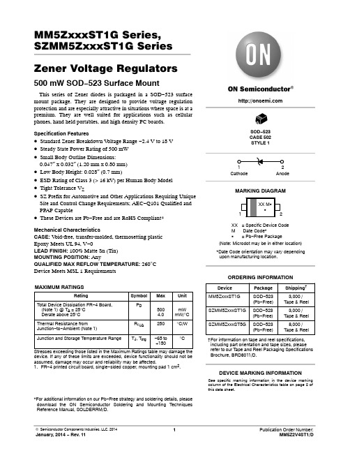
MM5ZxxxST1G Series, SZMM5ZxxxST1G Series Zener Voltage Regulators 500 mW SOD−523 Surface MountThis series of Zener diodes is packaged in a SOD−523 surface mount package. They are designed to provide voltage regulation protection and are especially attractive in situations where space is at a premium. They are well suited for applications such as cellular phones, hand held portables, and high density PC boards. Specification Features•Standard Zener Breakdown V oltage Range −2.4 V to 18 V •Steady State Power Rating of 500 mW•Small Body Outline Dimensions:0.047″ x 0.032″ (1.20 mm x 0.80 mm)•Low Body Height: 0.028″ (0.7 mm)•ESD Rating of Class 3 (> 16 kV) per Human Body Model •Tight Tolerance V Z•SZ Prefix for Automotive and Other Applications Requiring Unique Site and Control Change Requirements; AEC−Q101 Qualified and PPAP Capable•These Devices are Pb−Free and are RoHS Compliant*Mechanical CharacteristicsCASE:V oid-free, transfer-molded, thermosetting plasticEpoxy Meets UL 94, V−0LEAD FINISH: 100% Matte Sn (Tin)MOUNTING POSITION:AnyQUALIFIED MAX REFLOW TEMPERATURE: 260°CDevice Meets MSL 1 RequirementsMAXIMUM RATINGSRating Symbol Max UnitTotal Device Dissipation FR−4 Board, (Note 1) @ T A = 25°CDerate above 25°C P D5004.0mWmW/°CThermal Resistance from Junction−to−Ambient (Note 1)R q JA250°C/WJunction and Storage Temperature Range T J, T stg−65 to+150°CStresses exceeding those listed in the Maximum Ratings table may damage the device. If any of these limits are exceeded, device functionality should not be assumed, damage may occur and reliability may be affected.1.FR−4 printed circuit board, single−sided copper, mounting pad 1 cm2.*For additional information on our Pb−Free strategy and soldering details, please download the ON Semiconductor Soldering and Mounting Techniques Reference Manual, SOLDERRM/D.Device Package Shipping†ORDERING INFORMATIONCathode AnodeSee specific marking information in the device marking column of the Electrical Characteristics table on page 2 of this data sheet.DEVICE MARKING INFORMATIONSOD−523CASE 502STYLE 1MARKING DIAGRAMXX= Specific Device CodeM Date Code*G= Pb−Free Package(Note: Microdot may be in either location)*Date Code orientation may vary dependingupon manufacturing location.MM5ZxxxST1G SOD−523(Pb−Free)3,000 /Tape & Reel†For information on tape and reel specifications, including part orientation and tape sizes, please refer to our T ape and Reel Packaging Specifications Brochure, BRD8011/D.SOD−523(Pb−Free)SZMM5ZxxxST1G3,000 /Tape & ReelSOD−523(Pb−Free)SZMM5ZxxxST5G8,000 /Tape & ReelELECTRICAL CHARACTERISTICS (T A = 25°C unless otherwise noted,V F = 0.9 V Max. @ I F = 10 mA for all types) Symbol Parameter V Z Reverse Zener Voltage @ I ZTI ZT Reverse CurrentZZT Maximum Zener Impedance @ I ZTI ZK Reverse CurrentZ ZK Maximum Zener Impedance @ I ZKI R Reverse Leakage Current @ V RV R Reverse VoltageI F Forward CurrentV F Forward Voltage @ I FQ V Z Maximum Temperature Coefficient of V Z C Max. Capacitance @V R = 0 and f = 1 MHzV Figure 1. Zener Voltage RegulatorELECTRICAL CHARACTERISTICS (V F = 0.9 Max @ I F = 10 mA for all types)Device*DeviceMarkingTestCurrentIzt mAZener VoltageVZZ ZK I Z= 1.0mA WMaxZ ZTI Z = IZT@ 10%Mod WMaxMaxIR @ VRd VZ/dt (mV/k)@ I ZT1 = 5 mA C pF Max @V R = 0f = 1 MHzMin Max m A V Min MaxMM5Z2V4ST1G T2 5.0 2.43 2.631000100120 1.0−3.50450MM5Z2V7ST1G T3 5.0 2.67 2.911000100100 1.0−3.50450MM5Z3V3ST1G T5 5.0 3.32 3.53100095 5.0 1.0−3.50450MM5Z3V6ST1G T6 5.0 3.60 3.85100090 5.0 1.0−3.50450MM5Z3V9ST1G T7 5.0 3.89 4.16100090 3.0 1.0−3.5−2.5450MM5Z4V3ST1G T8 5.0 4.17 4.43100090 3.0 1.0−3.50450MM5Z4V7ST1G/T5G T9 5.0 4.55 4.7580080 3.0 2.0−3.50.2260MM5Z5V1ST1G TA 5.0 4.98 5.250060 2.0 2.0−2.7 1.2225MM5Z5V6ST1G TC 5.0 5.49 5.7320040 1.0 2.0−2.0 2.5200MM5Z6V2ST1G TE 5.0 6.06 6.3310010 3.0 4.00.4 3.7185MM5Z6V8ST1G TF 5.0 6.65 6.9316015 2.0 4.0 1.2 4.5155MM5Z7V5ST1G TG 5.07.287.616015 1.0 5.0 2.5 5.3140MM5Z8V2ST1G TH 5.08.028.36160150.7 5.0 3.2 6.2135MM5Z9V1ST1G TK 5.08.859.23160150.5 6.0 3.87.0130MM5Z12VST1G TN 5.011.7412.2480250.18.0 6.010130MM5Z16VST1G TU 5.015.8516.5180400.0511.210.414105MM5Z18VST1G TW 5.017.5618.3580450.0512.612.416100 Product parametric performance is indicated in the Electrical Characteristics for the listed test conditions, unless otherwise noted. Product performance may not be indicated by the Electrical Characteristics if operated under different conditions.*Include SZ-prefix devices where applicable.TYPICAL CHARACTERISTICSTEMPERATURE (°C)25010040200P O W E R D I S S I P A T I O N (%)50751001251508060Figure 2. Steady State Power DeratingPACKAGE DIMENSIONSSOD −523CASE 502ISSUE ENOTES:1.DIMENSIONING AND TOLERANCING PER ASME Y14.5M, 1994.2.CONTROLLING DIMENSION: MILLIMETERS.3.MAXIMUM LEAD THICKNESS INCLUDES LEAD FINISH.MINIMUM LEAD THICKNESS IS THE MINIMUM THICKNESS OF BASE MATERIAL.4.DIMENSIONS D AND E DO NOT INCLUDE MOLD FLASH, PRO-TRUSIONS, OR GATE BURRS.DIM MIN NOM MAX MILLIMETERS D 1.10 1.20 1.30E 0.700.800.90A 0.500.600.70b 0.250.300.35c 0.070.140.20L 0.30 REF H 1.50 1.60 1.70*For additional information on our Pb −Free strategy and soldering details, please download the ON Semiconductor Soldering and Mounting Techniques Reference Manual, SOLDERRM/D.SOLDERING FOOTPRINT*E RECOMMENDEDSIDE VIEW2XBOTTOM VIEWL2L2X2XL20.150.200.25STYLE 1:PIN 1.CATHODE (POLARITY BAND)2.ANODEON Semiconductor and are registered trademarks of Semiconductor Components Industries, LLC (SCILLC). SCILLC reserves the right to make changes without further notice to any products herein. SCILLC makes no warranty, representation or guarantee regarding the suitability of its products for any particular purpose, nor does SCILLC assume any liability arising out of the application or use of any product or circuit, and specifically disclaims any and all liability, including without limitation special, consequential or incidental damages.“Typical” parameters which may be provided in SCILLC data sheets and/or specifications can and do vary in different applications and actual performance may vary over time. All operating parameters, including “Typicals” must be validated for each customer application by customer’s technical experts. SCILLC does not convey any license under its patent rights nor the rights of others. SCILLC products are not designed, intended, or authorized for use as components in systems intended for surgical implant into the body, or other applications intended to support or sustain life, or for any other application in which the failure of the SCILLC product could create a situation where personal injury or death may occur. Should Buyer purchase or use SCILLC products for any such unintended or unauthorized application, Buyer shall indemnify and hold SCILLC and its officers, employees, subsidiaries, affiliates,and distributors harmless against all claims, costs, damages, and expenses, and reasonable attorney fees arising out of, directly or indirectly, any claim of personal injury or death associated with such unintended or unauthorized use, even if such claim alleges that SCILLC was negligent regarding the design or manufacture of the part. SCILLC is an Equal Opportunity/Affirmative Action Employer. This literature is subject to all applicable copyright laws and is not for resale in any manner.PUBLICATION ORDERING INFORMATION。
1.5KE16CA,TVS瞬变二极管中文资料
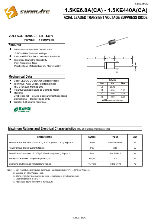
POWER: 1500Wa t VOLTAGE RANGE: 6.8 - 440 VAXIAL LEADED TRANSIENT VOLTAGE SUPPRESS DIODE1.5KE6.8A(CA) - 1.5KE440A(CA)6.8V – 440V Standoff VoltageCase: JEDEC DO-201AD Molded Plastic FeaturesGlass Passivated Die Construction Uni- and Bi-Directional Versions Available Excellent Clamping Capability Fast Response TimePlastic Case Material has UL FlammabilityMechanical DataTerminals: Axial Leads, Solderable per MIL-STD-202, Method 208 Polarity: Cathode Band or Cathode Notch Marking:Unidirectional – Device Code and Cathode Band Bidirectional – Device Code OnlyMaximum Ratings and Electrical Characteristics@T A =25°C unless otherwise specifiedCharacteristicSymbol ValueUnit Peak Pulse Power Dissipation at T A = 25°C (Note 1, 2, 5) Figure 3P PPM 1500 MinimumW Peak Forward Surge Current (Note 3)I FSM 200A Peak Pulse Current on 10/1000µS Waveform (Note 1) Figure 1I PPM See Table 1A Steady State Power Dissipation (Note 2, 4)P M(AV) 5.0W Operating and Storage Temperature RangeT j , T STG-65 to +175°CNote: 1. Non-repetitive current pulse, per Figure 1 and derated above T A = 25°C per Figure 4.2. Mounted on 40mm 2 copper pad.3. 8.3ms single half sine-wave duty cycle = 4 pulses per minutes maximum.4. Lead temperature at 75°C = T L .5. Peak pulse power waveform is 10/1000µS.!!!!!!!Weight: 1.20 grams (approx.)!94.085.57.0211.4510.513.4 1.5KE440CA1.5KE400CA 1.5KE350A 1.5KE220CA 1.5KE170CA 1.5KE150A 1.5KE82CA (uA)R RMW RMW@V leakage Reverse CurrentPulse Peak (A)Vc(V)(mA)BR MAX CurrentMax.BR MIN @I Min.Volgtage Breakdown (V)(BI)(Uni)Voltage Stand-Off Reverse Maximum Clamping V T PP(V)V @I Volgtage Breakdown Test (V)V T Volgtage @I PP 1.5KE62CA 1.5KE56CA 1.5KE51CA 1.5KE47CA 1.5KE43CA 1.5KE39CA 1.5KE36CA 1.5KE33CA 1.5KE30CA 1.5KE27CA 1.5KE24CA 1.5KE22CA 1.5KE20CA 1.5KE18CA 1.5KE16CA 1.5KE15CA 1.5KE13CA 1.5KE12CA 1.5KE11CA 1.5KE10CA 1.5KE9.1CA 1.5KE8.2CA 1.5KE7.5CA 1.5KE6.8CA 1.5KE6.8A 1.5KE7.5A 1.5KE8.2A 1.5KE9.1A 1.5KE10A 1.5KE11A 1.5KE12A 1.5KE13A 1.5KE15A 1.5KE16A 1.5KE18A 1.5KE20A 1.5KE22A 1.5KE24A 1.5KE27A 1.5KE30A 1.5KE33A 1.5KE36A 1.5KE39A1.5KE43A 1.5KE47A 1.5KE51A 1.5KE56A 1.5KE300CA 1.5KE250CA 1.5KE200CA 1.5KE180CA 1.5KE160CA 1.5KE150CA 1.5KE130CA 1.5KE120CA 1.5KE110CA 1.5KE100CA 1.5KE91CA 1.5KE75CA 1.5KE68CA 1.5KE62A 1.5KE68A 1.5KE75A 1.5KE82A 1.5KE91A 1.5KE100A 1.5KE110A 1.5KE120A 1.5KE130A 1.5KE160A 1.5KE170A 1.5KE180A 1.5KE200A 1.5KE220A 1.5KE250A 1.5KE300A 1.5KE400A 1.5KE440A1.5KE350CA 5.80 6.45 7.14 10 144.8 1000.06.407.13 7.88 10 11.3 134.5 500.0 7.79 8.61 10 12.1 125.6 200.0 7.78 8.65 9.55 1.0 113.4 50.0 8.55 9.50 10.5 1.0 14.5 104.8 10.0 9.40 10.11.6 1.0 15.6 97.4 5.0 10.212.6 1.0 16.7 91.0 5.011.1 12.4 13.7 1.0 18.2 83.5 5.0 12.8 14.3 15.8 1.0 21.2 71.75.013.615.2 16.8 1.0 22.5 67.6 5.0 15.3 17.1 18.9 1.0 25.2 60.3 5.0 17.1 19.0 21.0 1.0 27.7 54.9 5.0 18.820.923.1 1.0 30.6 49.7 5.020.5 22.8 25.2 1.0 33.2 45.8 5.023.1 25.7 28.4 1.0 37.5 40.5 5.0 25.6 28.5 31.5 1.0 41.4 36.7 5.0 28.2 31.4 34.7 1.0 45.7 33.3 5.030.8 34.2 37.8 1.0 49.9 30.5 5.033.3 37.1 41.0 1.0 53.9 28.2 5.0 36.8 40.9 45.2 1.0 59.3 25.6 5.0 40.2 44.7 49.4 1.0 64.8 23.5 5.0 43.648.553.6 1.0 70.1 21.7 5.047.8 53.2 58.8 1.0 77.0 19.7 5.053.0 58.9 65.1 1.0 85.0 17.9 5.058.1 64.6 71.4 1.0 92.0 16.5 5.0 64.1 71.3 78.8 1.0 103 14.8 5.0 70.1 77.9 86.1 1.0 113 13.5 5.0 77.8 86.5 95.5 1.0 125 12.2 5.095.0 105 1.0 137 11.1 5.0105 116 1.0 152 10.0 5.0102 114 126 1.0 165 9.2 5.0 111 124 137 1.0 179 8.5 5.0128 143 158 1.0 207 7.3 5.0136 152 168 1.0 219 6.9 5.0 145 162 179 1.0 234 6.5 5.0 154 171 189 1.0 246 6.2 5.0 171 190 210 1.0 274 5.5 5.0 185 209 231 1.0 328 4.6 5.0 214 237 263 1.0 344 4.4 5.0256 285 315 1.0 414 3.7 5.0300 333 368 1.0 482 3.2 5.0 342 380 420 1.0 548 2.8 5.0 376 418 462 1.0 600 2.5 5.0TYPE255075100125150175200100755025T ,AMBIENT TEMPERATURE (°C)Fig.4Pulse Derating CurveA P K P U L S E D E R A T I N G (%P K P W R O R C U R R E N T )25507510012515017520002.55.0T ,LEAD TEMPERATURE (°C)Fig.5,Steady State Power DeratingLP ,S T E A D Y S T A T E P O W E R D I S S I P A T I O N (W )d 0.11.0T ,PULSE WIDTH (µs)Fig.3Pulse Rating Curvep 0.1101001.010100100010000P ,P E A K P U L S E P O W E R (k W )P 0123I ,P E A K P U L S E C U R R E N T (%)P p pt,TIME (ms)Fig.1Pulse Waveform110100100010100100010,000V ,REVERSE STANDOFF VOLTAGE (V)Fig.2Typical Junction CapacitanceRWM C ,C A P A C I T A N C E (p F )j。
瞬态抑制二极管KE
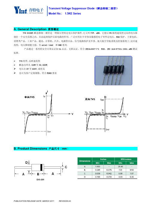
A.General Description简要概述
TVS DIODE:瞬态抑制二极管是一种限压型的过电压保护器件,它又叫TVP、ABD,它能以PS级的速度把过高的电压限制在一个安全范围之内,从而起到保护后面电路的作用。
广泛应用在半导体及敏感的电子零件过电压、ESD保护,主要包括:消费类产品、工业产品、通迅、计算机、汽车、电源供应品、信号线路保护及军事、航天航空导航系统及控制系统上;反应速度快,电压抑制能力强,有Axial lead和SMD系列.
产品通过一系列的安全可靠认证如UL认证、无铅认证,符合IEC61000-4-2ESD、IEC61643-321:2001ABD测试
标准。
瞬态功率从400W至30,000W;
电压由5V至600V,或更高
也可为客户定制规格、符合ROHS要求
产品尺寸(mm)
C.Electrical Characteristics电气参数
D.产品重要特性曲线(TA=25℃unless otherwise noted)
E.术语定义
F.Order information定购信息
1000PCS/BOX
NOTE:TERMINAL PAD SOLDERABILITY:
MEETS EIA SPECIFICATION RS186-9E
AND ANSI、J-STD-002CATEGORY3.
器件的焊接符合美国标准协会J-STD-002要求。
1.5KE300A,TVS瞬变二极管中文资料
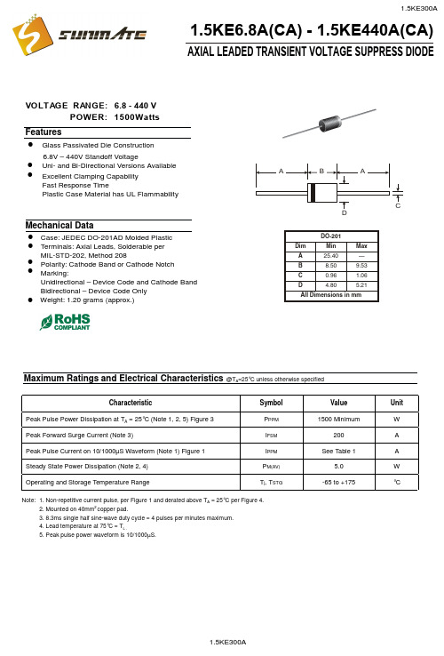
POWER: 1500Wa t VOLTAGE RANGE: 6.8 - 440 VAXIAL LEADED TRANSIENT VOLTAGE SUPPRESS DIODE1.5KE6.8A(CA) - 1.5KE440A(CA)6.8V – 440V Standoff VoltageCase: JEDEC DO-201AD Molded Plastic FeaturesGlass Passivated Die Construction Uni- and Bi-Directional Versions Available Excellent Clamping Capability Fast Response TimePlastic Case Material has UL FlammabilityMechanical DataTerminals: Axial Leads, Solderable per MIL-STD-202, Method 208 Polarity: Cathode Band or Cathode Notch Marking:Unidirectional – Device Code and Cathode Band Bidirectional – Device Code OnlyMaximum Ratings and Electrical Characteristics@T A =25°C unless otherwise specifiedCharacteristicSymbol ValueUnit Peak Pulse Power Dissipation at T A = 25°C (Note 1, 2, 5) Figure 3P PPM 1500 MinimumW Peak Forward Surge Current (Note 3)I FSM 200A Peak Pulse Current on 10/1000µS Waveform (Note 1) Figure 1I PPM See Table 1A Steady State Power Dissipation (Note 2, 4)P M(AV) 5.0W Operating and Storage Temperature RangeT j , T STG-65 to +175°CNote: 1. Non-repetitive current pulse, per Figure 1 and derated above T A = 25°C per Figure 4.2. Mounted on 40mm 2 copper pad.3. 8.3ms single half sine-wave duty cycle = 4 pulses per minutes maximum.4. Lead temperature at 75°C = T L .5. Peak pulse power waveform is 10/1000µS.!!!!!!!Weight: 1.20 grams (approx.)!94.085.57.0211.4510.513.4 1.5KE440CA1.5KE400CA 1.5KE350A 1.5KE220CA 1.5KE170CA 1.5KE150A 1.5KE82CA (uA)R RMW RMW@V leakage Reverse CurrentPulse Peak (A)Vc(V)(mA)BR MAX CurrentMax.BR MIN @I Min.Volgtage Breakdown (V)(BI)(Uni)Voltage Stand-Off Reverse Maximum Clamping V T PP(V)V @I Volgtage Breakdown Test (V)V T Volgtage @I PP 1.5KE62CA 1.5KE56CA 1.5KE51CA 1.5KE47CA 1.5KE43CA 1.5KE39CA 1.5KE36CA 1.5KE33CA 1.5KE30CA 1.5KE27CA 1.5KE24CA 1.5KE22CA 1.5KE20CA 1.5KE18CA 1.5KE16CA 1.5KE15CA 1.5KE13CA 1.5KE12CA 1.5KE11CA 1.5KE10CA 1.5KE9.1CA 1.5KE8.2CA 1.5KE7.5CA 1.5KE6.8CA 1.5KE6.8A 1.5KE7.5A 1.5KE8.2A 1.5KE9.1A 1.5KE10A 1.5KE11A 1.5KE12A 1.5KE13A 1.5KE15A 1.5KE16A 1.5KE18A 1.5KE20A 1.5KE22A 1.5KE24A 1.5KE27A 1.5KE30A 1.5KE33A 1.5KE36A 1.5KE39A1.5KE43A 1.5KE47A 1.5KE51A 1.5KE56A 1.5KE300CA 1.5KE250CA 1.5KE200CA 1.5KE180CA 1.5KE160CA 1.5KE150CA 1.5KE130CA 1.5KE120CA 1.5KE110CA 1.5KE100CA 1.5KE91CA 1.5KE75CA 1.5KE68CA 1.5KE62A 1.5KE68A 1.5KE75A 1.5KE82A 1.5KE91A 1.5KE100A 1.5KE110A 1.5KE120A 1.5KE130A 1.5KE160A 1.5KE170A 1.5KE180A 1.5KE200A 1.5KE220A 1.5KE250A 1.5KE300A 1.5KE400A 1.5KE440A1.5KE350CA 5.80 6.45 7.14 10 144.8 1000.06.407.13 7.88 10 11.3 134.5 500.0 7.79 8.61 10 12.1 125.6 200.0 7.78 8.65 9.55 1.0 113.4 50.0 8.55 9.50 10.5 1.0 14.5 104.8 10.0 9.40 10.11.6 1.0 15.6 97.4 5.0 10.212.6 1.0 16.7 91.0 5.011.1 12.4 13.7 1.0 18.2 83.5 5.0 12.8 14.3 15.8 1.0 21.2 71.75.013.615.2 16.8 1.0 22.5 67.6 5.0 15.3 17.1 18.9 1.0 25.2 60.3 5.0 17.1 19.0 21.0 1.0 27.7 54.9 5.0 18.820.923.1 1.0 30.6 49.7 5.020.5 22.8 25.2 1.0 33.2 45.8 5.023.1 25.7 28.4 1.0 37.5 40.5 5.0 25.6 28.5 31.5 1.0 41.4 36.7 5.0 28.2 31.4 34.7 1.0 45.7 33.3 5.030.8 34.2 37.8 1.0 49.9 30.5 5.033.3 37.1 41.0 1.0 53.9 28.2 5.0 36.8 40.9 45.2 1.0 59.3 25.6 5.0 40.2 44.7 49.4 1.0 64.8 23.5 5.0 43.648.553.6 1.0 70.1 21.7 5.047.8 53.2 58.8 1.0 77.0 19.7 5.053.0 58.9 65.1 1.0 85.0 17.9 5.058.1 64.6 71.4 1.0 92.0 16.5 5.0 64.1 71.3 78.8 1.0 103 14.8 5.0 70.1 77.9 86.1 1.0 113 13.5 5.0 77.8 86.5 95.5 1.0 125 12.2 5.095.0 105 1.0 137 11.1 5.0105 116 1.0 152 10.0 5.0102 114 126 1.0 165 9.2 5.0 111 124 137 1.0 179 8.5 5.0128 143 158 1.0 207 7.3 5.0136 152 168 1.0 219 6.9 5.0 145 162 179 1.0 234 6.5 5.0 154 171 189 1.0 246 6.2 5.0 171 190 210 1.0 274 5.5 5.0 185 209 231 1.0 328 4.6 5.0 214 237 263 1.0 344 4.4 5.0256 285 315 1.0 414 3.7 5.0300 333 368 1.0 482 3.2 5.0 342 380 420 1.0 548 2.8 5.0 376 418 462 1.0 600 2.5 5.0TYPE255075100125150175200100755025T ,AMBIENT TEMPERATURE (°C)Fig.4Pulse Derating CurveA P K P U L S E D E R A T I N G (%P K P W R O R C U R R E N T )25507510012515017520002.55.0T ,LEAD TEMPERATURE (°C)Fig.5,Steady State Power DeratingLP ,S T E A D Y S T A T E P O W E R D I S S I P A T I O N (W )d 0.11.0T ,PULSE WIDTH (µs)Fig.3Pulse Rating Curvep 0.1101001.010100100010000P ,P E A K P U L S E P O W E R (k W )P 0123I ,P E A K P U L S E C U R R E N T (%)P p pt,TIME (ms)Fig.1Pulse Waveform110100100010100100010,000V ,REVERSE STANDOFF VOLTAGE (V)Fig.2Typical Junction CapacitanceRWM C ,C A P A C I T A N C E (p F )j。
1.5KE250A参数资料
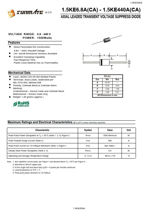
POWER: 1500Wa t VOLTAGE RANGE: 6.8 - 440 VAXIAL LEADED TRANSIENT VOLTAGE SUPPRESS DIODE1.5KE6.8A(CA) - 1.5KE440A(CA)6.8V – 440V Standoff VoltageCase: JEDEC DO-201AD Molded Plastic FeaturesGlass Passivated Die Construction Uni- and Bi-Directional Versions Available Excellent Clamping Capability Fast Response TimePlastic Case Material has UL FlammabilityMechanical DataTerminals: Axial Leads, Solderable per MIL-STD-202, Method 208 Polarity: Cathode Band or Cathode Notch Marking:Unidirectional – Device Code and Cathode Band Bidirectional – Device Code OnlyMaximum Ratings and Electrical Characteristics@T A =25°C unless otherwise specifiedCharacteristicSymbol Value Unit Peak Pulse Power Dissipation at T A = 25°C (Note 1, 2, 5) Figure 3P PPM 1500 MinimumW Peak Forward Surge Current (Note 3)I FSM 200A Peak Pulse Current on 10/1000µS Waveform (Note 1) Figure 1I PPM See Table 1A Steady State Power Dissipation (Note 2, 4)P M(AV) 5.0W Operating and Storage Temperature RangeT j , T STG-65 to +175°CNote: 1. Non-repetitive current pulse, per Figure 1 and derated above T A = 25°C per Figure 4.2. Mounted on 40mm 2 copper pad.3. 8.3ms single half sine-wave duty cycle = 4 pulses per minutes maximum.4. Lead temperature at 75°C = T L .5. Peak pulse power waveform is 10/1000µS.!!!!!!!Weight: 1.20 grams (approx.)!森美特94.085.57.0211.4510.513.4 1.5KE440CA1.5KE400CA 1.5KE350A 1.5KE220CA 1.5KE170CA 1.5KE150A 1.5KE82CA (uA)R RMW RMW@V leakage Reverse CurrentPulse Peak (A)Vc(V)(mA)BR MAX CurrentMax.BR MIN @I Min.Volgtage Breakdown (V)(BI)(Uni)Voltage Stand-Off Reverse Maximum Clamping V T PP(V)V @I Volgtage Breakdown Test (V)V T Volgtage @I PP 1.5KE62CA 1.5KE56CA 1.5KE51CA 1.5KE47CA 1.5KE43CA 1.5KE39CA 1.5KE36CA 1.5KE33CA 1.5KE30CA 1.5KE27CA 1.5KE24CA 1.5KE22CA 1.5KE20CA 1.5KE18CA 1.5KE16CA 1.5KE15CA 1.5KE13CA 1.5KE12CA 1.5KE11CA 1.5KE10CA 1.5KE9.1CA 1.5KE8.2CA 1.5KE7.5CA 1.5KE6.8CA 1.5KE6.8A 1.5KE7.5A 1.5KE8.2A 1.5KE9.1A 1.5KE10A 1.5KE11A 1.5KE12A 1.5KE13A 1.5KE15A 1.5KE16A 1.5KE18A 1.5KE20A 1.5KE22A 1.5KE24A 1.5KE27A 1.5KE30A 1.5KE33A1.5KE36A 1.5KE39A 1.5KE43A 1.5KE47A 1.5KE51A 1.5KE56A 1.5KE300CA 1.5KE250CA 1.5KE200CA 1.5KE180CA 1.5KE160CA 1.5KE150CA 1.5KE130CA 1.5KE120CA 1.5KE110CA 1.5KE100CA 1.5KE91CA 1.5KE75CA 1.5KE68CA 1.5KE62A 1.5KE68A 1.5KE75A 1.5KE82A 1.5KE91A 1.5KE100A 1.5KE110A 1.5KE120A 1.5KE130A 1.5KE160A 1.5KE170A 1.5KE180A 1.5KE200A 1.5KE220A 1.5KE250A 1.5KE300A 1.5KE400A 1.5KE440A1.5KE350CA 5.80 6.45 7.14 10 144.8 1000.06.407.13 7.88 10 11.3 134.5 500.0 7.79 8.61 10 12.1 125.6 200.0 7.78 8.65 9.55 1.0 113.4 50.0 8.55 9.50 10.5 1.0 14.5 104.8 10.0 9.40 10.11.6 1.0 15.6 97.4 5.0 10.212.6 1.0 16.7 91.0 5.011.1 12.4 13.7 1.0 18.2 83.5 5.0 12.8 14.3 15.8 1.0 21.2 71.75.013.615.2 16.8 1.0 22.5 67.6 5.0 15.3 17.1 18.9 1.0 25.2 60.3 5.0 17.1 19.0 21.0 1.0 27.7 54.9 5.0 18.820.923.1 1.0 30.6 49.7 5.020.5 22.8 25.2 1.0 33.2 45.8 5.023.1 25.7 28.4 1.0 37.5 40.5 5.0 25.6 28.5 31.5 1.0 41.4 36.7 5.0 28.2 31.4 34.7 1.0 45.7 33.3 5.030.8 34.2 37.8 1.0 49.9 30.5 5.033.3 37.1 41.0 1.0 53.9 28.2 5.0 36.8 40.9 45.2 1.0 59.3 25.6 5.0 40.2 44.7 49.4 1.0 64.8 23.5 5.0 43.648.553.6 1.0 70.1 21.7 5.047.8 53.2 58.8 1.0 77.0 19.7 5.053.0 58.9 65.1 1.0 85.0 17.9 5.058.1 64.6 71.4 1.0 92.0 16.5 5.0 64.1 71.3 78.8 1.0 103 14.8 5.0 70.1 77.9 86.1 1.0 113 13.5 5.0 77.8 86.5 95.5 1.0 125 12.2 5.095.0 105 1.0 137 11.1 5.0105 116 1.0 152 10.0 5.0102 114 126 1.0 165 9.2 5.0 111 124 137 1.0 179 8.5 5.0128 143 158 1.0 207 7.3 5.0136 152 168 1.0 219 6.9 5.0 145 162 179 1.0 234 6.5 5.0 154 171 189 1.0 246 6.2 5.0 171 190 210 1.0 274 5.5 5.0 185 209 231 1.0 328 4.6 5.0 214 237 263 1.0 344 4.4 5.0256 285 315 1.0 414 3.7 5.0300 333 368 1.0 482 3.2 5.0 342 380 420 1.0 548 2.8 5.0 376 418 462 1.0 600 2.5 5.0TYPE森美特255075100125150175200100755025T ,AMBIENT TEMPERATURE (°C)Fig.4Pulse Derating CurveA P K P U L S E D E R A T I N G (%P K P W R O R C U R R E N T )25507510012515017520002.55.0T ,LEAD TEMPERATURE (°C)Fig.5,Steady State Power DeratingLP ,S T E A D Y S T A T E P O W E R D I S S I P A T I O N (W )d 0.11.0T ,PULSE WIDTH (µs)Fig.3Pulse Rating Curvep 0.1101001.010100100010000P ,P E A K P U L S E P O W E R (k W )P0123I ,P E A K P U L S E C U R R E N T (%)P p pt,TIME (ms)Fig.1Pulse Waveform110100100010100100010,000V ,REVERSE STANDOFF VOLTAGE (V)Fig.2Typical Junction CapacitanceRWM C ,C A P A C I T A N C E (p F )j 森美特。
1.5KE200A参数资料
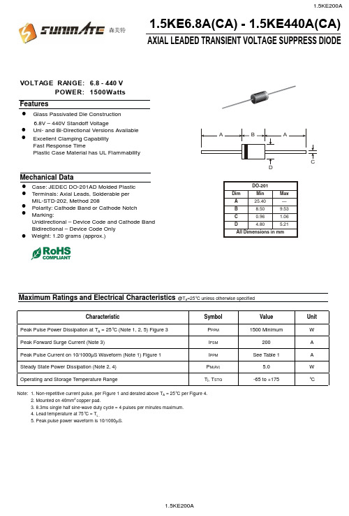
POWER: 1500Wa t VOLTAGE RANGE: 6.8 - 440 VAXIAL LEADED TRANSIENT VOLTAGE SUPPRESS DIODE1.5KE6.8A(CA) - 1.5KE440A(CA)6.8V – 440V Standoff VoltageCase: JEDEC DO-201AD Molded Plastic FeaturesGlass Passivated Die Construction Uni- and Bi-Directional Versions Available Excellent Clamping Capability Fast Response TimePlastic Case Material has UL FlammabilityMechanical DataTerminals: Axial Leads, Solderable per MIL-STD-202, Method 208 Polarity: Cathode Band or Cathode Notch Marking:Unidirectional – Device Code and Cathode Band Bidirectional – Device Code OnlyMaximum Ratings and Electrical Characteristics@T A =25°C unless otherwise specifiedCharacteristicSymbol Value Unit Peak Pulse Power Dissipation at T A = 25°C (Note 1, 2, 5) Figure 3P PPM 1500 MinimumW Peak Forward Surge Current (Note 3)I FSM 200A Peak Pulse Current on 10/1000µS Waveform (Note 1) Figure 1I PPM See Table 1A Steady State Power Dissipation (Note 2, 4)P M(AV) 5.0W Operating and Storage Temperature RangeT j , T STG-65 to +175°CNote: 1. Non-repetitive current pulse, per Figure 1 and derated above T A = 25°C per Figure 4.2. Mounted on 40mm 2 copper pad.3. 8.3ms single half sine-wave duty cycle = 4 pulses per minutes maximum.4. Lead temperature at 75°C = T L .5. Peak pulse power waveform is 10/1000µS.!!!!!!!Weight: 1.20 grams (approx.)!森美特94.085.57.0211.4510.513.4 1.5KE440CA1.5KE400CA 1.5KE350A 1.5KE220CA 1.5KE170CA 1.5KE150A 1.5KE82CA (uA)R RMW RMW@V leakage Reverse CurrentPulse Peak (A)Vc(V)(mA)BR MAX CurrentMax.BR MIN @I Min.Volgtage Breakdown (V)(BI)(Uni)Voltage Stand-Off Reverse Maximum Clamping V T PP(V)V @I Volgtage Breakdown Test (V)V T Volgtage @I PP 1.5KE62CA 1.5KE56CA 1.5KE51CA 1.5KE47CA 1.5KE43CA 1.5KE39CA 1.5KE36CA 1.5KE33CA 1.5KE30CA 1.5KE27CA 1.5KE24CA 1.5KE22CA 1.5KE20CA 1.5KE18CA 1.5KE16CA 1.5KE15CA 1.5KE13CA 1.5KE12CA 1.5KE11CA 1.5KE10CA 1.5KE9.1CA 1.5KE8.2CA 1.5KE7.5CA 1.5KE6.8CA 1.5KE6.8A 1.5KE7.5A 1.5KE8.2A 1.5KE9.1A 1.5KE10A 1.5KE11A 1.5KE12A 1.5KE13A 1.5KE15A 1.5KE16A 1.5KE18A 1.5KE20A 1.5KE22A 1.5KE24A 1.5KE27A 1.5KE30A 1.5KE33A1.5KE36A 1.5KE39A 1.5KE43A 1.5KE47A 1.5KE51A 1.5KE56A 1.5KE300CA 1.5KE250CA 1.5KE200CA 1.5KE180CA 1.5KE160CA 1.5KE150CA 1.5KE130CA 1.5KE120CA 1.5KE110CA 1.5KE100CA 1.5KE91CA 1.5KE75CA 1.5KE68CA 1.5KE62A 1.5KE68A 1.5KE75A 1.5KE82A 1.5KE91A 1.5KE100A 1.5KE110A 1.5KE120A 1.5KE130A 1.5KE160A 1.5KE170A 1.5KE180A 1.5KE200A 1.5KE220A 1.5KE250A 1.5KE300A 1.5KE400A 1.5KE440A1.5KE350CA 5.80 6.45 7.14 10 144.8 1000.06.407.13 7.88 10 11.3 134.5 500.0 7.79 8.61 10 12.1 125.6 200.0 7.78 8.65 9.55 1.0 113.4 50.0 8.55 9.50 10.5 1.0 14.5 104.8 10.0 9.40 10.11.6 1.0 15.6 97.4 5.0 10.212.6 1.0 16.7 91.0 5.011.1 12.4 13.7 1.0 18.2 83.5 5.0 12.8 14.3 15.8 1.0 21.2 71.75.013.615.2 16.8 1.0 22.5 67.6 5.0 15.3 17.1 18.9 1.0 25.2 60.3 5.0 17.1 19.0 21.0 1.0 27.7 54.9 5.0 18.820.923.1 1.0 30.6 49.7 5.020.5 22.8 25.2 1.0 33.2 45.8 5.023.1 25.7 28.4 1.0 37.5 40.5 5.0 25.6 28.5 31.5 1.0 41.4 36.7 5.0 28.2 31.4 34.7 1.0 45.7 33.3 5.030.8 34.2 37.8 1.0 49.9 30.5 5.033.3 37.1 41.0 1.0 53.9 28.2 5.0 36.8 40.9 45.2 1.0 59.3 25.6 5.0 40.2 44.7 49.4 1.0 64.8 23.5 5.0 43.648.553.6 1.0 70.1 21.7 5.047.8 53.2 58.8 1.0 77.0 19.7 5.053.0 58.9 65.1 1.0 85.0 17.9 5.058.1 64.6 71.4 1.0 92.0 16.5 5.0 64.1 71.3 78.8 1.0 103 14.8 5.0 70.1 77.9 86.1 1.0 113 13.5 5.0 77.8 86.5 95.5 1.0 125 12.2 5.095.0 105 1.0 137 11.1 5.0105 116 1.0 152 10.0 5.0102 114 126 1.0 165 9.2 5.0 111 124 137 1.0 179 8.5 5.0128 143 158 1.0 207 7.3 5.0136 152 168 1.0 219 6.9 5.0 145 162 179 1.0 234 6.5 5.0 154 171 189 1.0 246 6.2 5.0 171 190 210 1.0 274 5.5 5.0 185 209 231 1.0 328 4.6 5.0 214 237 263 1.0 344 4.4 5.0256 285 315 1.0 414 3.7 5.0300 333 368 1.0 482 3.2 5.0 342 380 420 1.0 548 2.8 5.0 376 418 462 1.0 600 2.5 5.0TYPE森美特255075100125150175200100755025T ,AMBIENT TEMPERATURE (°C)Fig.4Pulse Derating CurveA P K P U L S E D E R A T I N G (%P K P W R O R C U R R E N T )25507510012515017520002.55.0T ,LEAD TEMPERATURE (°C)Fig.5,Steady State Power DeratingLP ,S T E A D Y S T A T E P O W E R D I S S I P A T I O N (W )d 0.11.0T ,PULSE WIDTH (µs)Fig.3Pulse Rating Curvep 0.1101001.010100100010000P ,P E A K P U L S E P O W E R (k W )P0123I ,P E A K P U L S E C U R R E N T (%)P p pt,TIME (ms)Fig.1Pulse Waveform110100100010100100010,000V ,REVERSE STANDOFF VOLTAGE (V)Fig.2Typical Junction CapacitanceRWM C ,C A P A C I T A N C E (p F )j 森美特。
1.5KE440A,1.5KE440CA
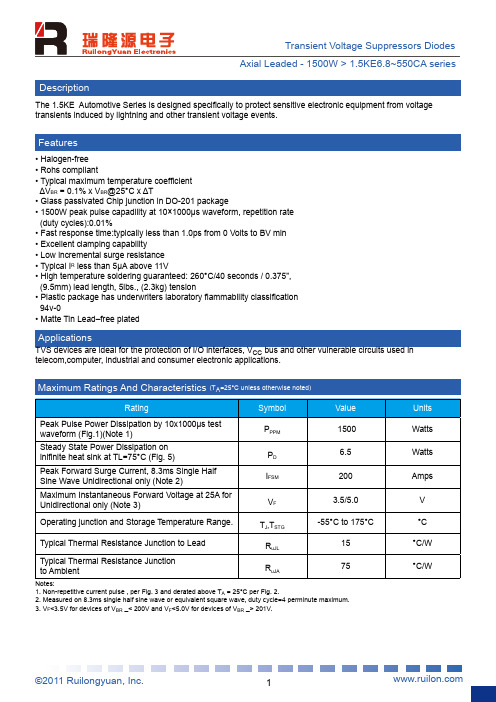
TVS devices are ideal for the protection of I/O interfaces, VCC bus and other vulnerable circuits used in telecom,computer, industrial and consumer electronic applications.
(UNI)
(BI)
VRWM(V)
VBR MIN.(V)
VBR.MAX.(V)
1.5KE6.8A 1.5KE6.8CA
5.80
6.45
7.14
1.5KE7.5A 1.5KE7.5CA
6.40
7.13
7.88
1.5KE8.2A 1.5KE8.2CA
7.027.79来自8.611.5KE9.1A 1.5KE9.1CA
Symbol PPPM PD IFSM VF
Value 1500 6.5 200 3.5/5.0
Operating junction and Storage Temperature Range.
TJ,TSTG
-55°C to 175°C
Typical Thermal Resistance Junction to Lead
2
Transient Voltage Suppressors Diodes Axial Leaded - 1500W > 1.5KE6.8~550CA series
Ratings and Characteristic Curves (TA=25°C unless otherwise noted)
(duty cycles):0.01% • Fast response time:typically less than 1.0ps from 0 Volts to BV min • Excellent clamping capability • Low incremental surge resistance • Typical IR less than 5μA above 11V • High temperature soldering guaranteed: 260°C/40 seconds / 0.375”,
Vishay 超导压差压电阻产品参数手册说明书

1.5KE160CA-E3/54 1.5KE47CA-E3/541.5KE6.8A thru 1.5KE540A, 1N6267A thru 1N6303AVishay General SemiconductorT RANS Z ORB ® Transient Voltage SuppressorsDEVICES FOR BI-DIRECTION APPLICATIONSFor bi-directional types, use CA suffix (e.g. 1.5KE220CA) Electrical characteristics apply in both directions.FEATURES•Glass passivated chip junction•Available in uni-directional and bi-directional •1500 W peak pulse power capability with a 10/1000 μs waveform, repetitive rate (duty cycle): 0.01 %•Excellent clamping capability •Very fast response time•Low incremental surge resistance•AEC-Q101 qualified•Solder dip 275 °C max. 10 s, per JESD 22-B106•Material categorization: for definitions of compliance please see /doc?99912TYPICAL APPLICATIONSUse in sensitive electronics protection against voltage transients induced by inductive load switching and lighting on ICs, MOSFET, signal lines of sensor units for consumer, computer, industrial, automotive, and telecommunication.MECHANICAL DATACase: molded epoxy body over passivated junction Molding compound meets UL 94 V-0 flammability rating Base P/N-E3 - RoHS compliant, commercial gradeBase P/NHE3_X - RoHS compliant, and AEC-Q101 qualified (“X” denotes revision code e.g. A, B, ...)Terminals: matte tin plated leads, solderable per J-STD-002 and JESD 22-B102E3 suffix meets JESD 201 class 1A whisker test, HE3 suffix meets JESD 201 class 2 whisker testNote• 1.5KE250A to 1.5KE540A are commercial grade only•Bi-directional is available from 1.5KE6.8CA to 1.5KE220CA onlyPolarity: For uni-directional types the color band denotes cathode end, no marking on bi-directional typesNotes(1)Non-repetitive current pulse, per fig. 3 and derated above T A= 25 °C per fig. 2(2)Measured on 8.3 ms single half sine-wave or equivalent square wave, duty cycle = 4 pulses per minute maximum (3)V F = 3.5 V for 1.5KE220A and below; V F= 5.0 V for 1.5KE250A and above PRIMARY CHARACTERISTICSV BR uni-directional 6.8 V to 540 V V BR bi-directional 6.8 V to 220 V V WM uni-directional 5.8 V to 459 V V WM bi-directional5.8 V to 185 V P PPM 1500 W P D6.5 W I FSM (uni-directional only)200 A T J max.175 °CPolarity Uni-directional, bi-directionalPackage1.5KEMAXIMUM RATINGS (T A = 25 °C unless otherwise noted)PARAMETERSYMBOL VALUE UNIT Peak pulse power dissipation with a 10/1000 μs waveform (1) (fig. 1)P PPM 1500W Peak pulse current with a 10/1000 μs waveform (1) I PPM See next tableA Power dissipation on infinite heatsink at T L = 75 °C (fig. 5)P D 6.5W Peak forward surge current 8.3 ms single half sine-wave uni-directional only (2)I FSM 200A Maximum instantaneous forward voltage at 100 A for uni-directional only (3) V F 3.5/5.0V Operating junction and storage temperature rangeT J , T STG-55 to +175°C1.5KE6.8A thru 1.5KE540A, 1N6267A thru 1N6303AVishay General SemiconductorNotes(1) Pulse test: t p≤ 50 ms (2) S urge current waveform per fig. 3 and derate per fig. 2(3) All terms and symbols are consistent with ANSI/IEEE CA62.35(4) For bi-directional types with V R 10 V and less the I Dlimit is doubled (+) Underwriters laboratory recognition for the classification of protectors (QVGQ2) under the UL standard for safety 497B and file number E136766 for both uni-directional and bi-directional devicesELECTRICAL CHARACTERISTICS (T A = 25 °C unless otherwise noted)JEDEC ® TYPE NUMBER GENERAL SEMICONDUCTOR PART NUMBER BREAKDOWN VOLTAGE V BR AT I T (1)(V) TEST CURRENT I T (mA)STAND-OFF VOLTAGE V WM (V)MAXIMUM REVERSE LEAKAGE AT V WM I D (4) (μA) MAXIMUM PEAKPULSECURRENT I PPM (2)(A)MAXIMUM CLAMPING VOLTAGE AT I PPM V C (V) MAXIMUM TEMPERATURE COEFFICIENTOF V BR (%/°C)MIN.MAX.1N6267A (+)1.5KE6.8A 6.457.1410 5.80100014310.50.0571N6268A (+)1.5KE7.5A 7.137.8810 6.4050013311.30.0611N6269A (+)1.5KE8.2A 7.798.61107.022*******.10.0651N6270A (+)1.5KE9.1A 8.659.55 1.07.785011213.40.0681N6271A (+)1.5KE10A 9.5010.5 1.08.551010314.50.0731N6272A (+)1.5KE11A 10.511.6 1.09.40 5.096.215.60.0751N6273A (+)1.5KE12A 11.412.6 1.010.2 5.089.816.70.0781N6274A (+)1.5KE13A 12.413.7 1.011.1 5.082.418.20.0811N6275A (+)1.5KE15A 14.315.8 1.012.8 1.070.821.20.0841N6276A (+)1.5KE16A 15.216.8 1.013.6 1.066.722.50.0861N6277A (+)1.5KE18A 17.118.9 1.015.3 1.059.525.20.0891N6278A (+)1.5KE20A 19.021.0 1.017.1 1.054.227.70.0901N6279A (+)1.5KE22A 20.923.1 1.018.8 1.049.030.60.0921N6280A (+)1.5KE24A 22.825.2 1.020.5 1.045.233.20.0941N6281A (+)1.5KE27A 25.728.4 1.023.1 1.040.037.50.0961N6282A (+)1.5KE30A 28.531.5 1.025.6 1.036.241.40.0971N6283A (+)1.5KE33A 31.434.7 1.028.2 1.032.845.70.0981N6284A (+)1.5KE36A 34.237.8 1.030.8 1.030.149.90.0991N6285A (+)1.5KE39A 37.141.0 1.033.3 1.027.853.90.1001N6286A (+)1.5KE43A 40.945.2 1.036.8 1.025.359.30.1011N6287A (+)1.5KE47A 44.749.4 1.040.2 1.023.164.80.1011N6288A (+)1.5KE51A 48.553.6 1.043.6 1.021.470.10.1021N6289A (+)1.5KE56A 53.258.8 1.047.8 1.019.577.00.1031N6290A (+)1.5KE62A 58.965.1 1.053.0 1.017.685.00.1041N6291A (+)1.5KE68A 64.671.4 1.058.1 1.016.392.00.1041N6292A (+)1.5KE75A 71.378.8 1.064.1 1.014.61040.1051N6293A (+)1.5KE82A 77.986.1 1.070.1 1.013.31130.1051N6294A (+)1.5KE91A 86.595.5 1.077.8 1.012.01250.1061N6295A (+)1.5KE100A 95.0105 1.085.5 1.010.91370.1061N6296A (+)1.5KE110A 105116 1.094.0 1.09.91520.1071N6297A (+)1.5KE120A 114126 1.0102 1.09.11650.1071N6298A (+)1.5KE130A 124137 1.0111 1.08.41790.1071N6299A (+)1.5KE150A 143158 1.0128 1.07.22070.1061N6300A (+)1.5KE160A 152168 1.0136 1.0 6.82190.1081N6301A (+)1.5KE170A 162179 1.0145 1.0 6.42340.1081N6302A (+)1.5KE180A 171189 1.0154 1.0 6.12460.1081N6303A (+)1.5KE200A 190210 1.0171 1.0 5.52740.108-(+)1.5KE220A 209231 1.0185 1.0 4.63280.108- 1.5KE250A 237263 1.0214 1.0 4.43440.110- 1.5KE300A 285315 1.0256 1.0 3.64140.110- 1.5KE350A 333368 1.0300 1.0 3.14820.110- 1.5KE400A 380420 1.0342 1.0 2.75480.110- 1.5KE440A 418462 1.0376 1.0 2.56020.110- 1.5KE480A 456504 1.0408 1.0 2.286580.110- 1.5KE510A 485535 1.0434 1.0 2.156980.110- 1.5KE540A 513567 1.0459 1.0 2.037400.1101.5KE6.8A thru 1.5KE540A, 1N6267A thru 1N6303A Vishay General Semiconductor Notes(1)AEC-Q101 qualified(2)Applied for 1.5KE6.8AHE3_A to 1.5KE220AHE3_A, and 1.5KE6.8CAHE3_A to 1.5KE220CAHE3_ARATINGS AND CHARACTERISTICS CURVES (T A = 25 °C unless otherwise noted)Fig. 1 - Peak Pulse Power Rating CurveFig. 2 - Pulse Power or Current vs. Initial Junction TemperatureFig. 3 - Pulse WaveformFig. 4 - Typical Junction CapacitanceTHERMAL CHARACTERISTICS (T A = 25 °C unless otherwise noted)PARAMETER SYMBOL VALUE UNIT Typical thermal resistance, junction to ambient RθJA75°C/ W Typical thermal resistance, junction to lead RθJL15.4ORDERING INFORMATION (Example)PREFERRED PIN UNIT WEIGHT (g)PREFERRED PACKAGE CODE BASE QUANTITY DELIVERY MODE1.5KE6.8A-E3/540.96854140013" diameter paper tape and reel 1.5KE6.8AHE3_A/C (1)(2)0.968C140013" diameter paper tape and reel1.5KE6.8A thru 1.5KE540A, 1N6267A thru 1N6303A Vishay General SemiconductorFig. 5 - Power Derating CurveFig. 6 - Maximum Non-Repetitive Forward Surge CurrentUni-Directional onlyFig. 7 - Incremental Clamping Voltage Curve (Uni-Directional)Fig. 8 - Incremental Clamping Voltage Curve (Uni-directional) Fig. 9 - Incremental Clamping Voltage Curve (Bi-directional) Fig. 10 - Incremental Clamping Voltage Curve (Bi-Directional)1.5KE6.8A thru 1.5KE540A, 1N6267A thru 1N6303A Vishay General SemiconductorFig. 11 - Instantaneous Forward Voltage Characteristics Curve Fig. 12 - Typical Transient Thermal Impedance PACKAGE OUTLINE DIMENSIONS in inches (millimeters)APPLICATION NOTES•This series of Silicon Transient Suppressors is used in applications where large voltage transients can permanently damage voltage-sensitive components.•The TVS diode can be used in applications where induced lightning on rural or remote transmission lines presents a hazard to electronic circuitry (ref: R.E.A. specification P.E. 60). •This Transient Voltage Suppressor diode has a pulse power rating of 1500 W for 1 ms. The response time of TVS diode clamping action is effectively instantaneous (1 x 10⁻⁹ s bi-directional); therefore, they can protect integrated circuits, MOS devices, hybrids, and other voltage sensitive semiconductors and components. TVS diodes can also be used in series or parallel to increase the peak power ratings.Legal Disclaimer Notice VishayDisclaimerALL PRODUCT, PRODUCT SPECIFICAT IONS AND DAT A ARE SUBJECT T O CHANGE WIT HOUT NOT ICE T O IMPROVE RELIABILITY, FUNCTION OR DESIGN OR OTHERWISE.Vishay Intertechnology, Inc., its affiliates, agents, and employees, and all persons acting on its or their behalf (collectively, “Vishay”), disclaim any and all liability for any errors, inaccuracies or incompleteness contained in any datasheet or in any other disclosure relating to any product.Vishay makes no warranty, representation or guarantee regarding the suitability of the products for any particular purpose or the continuing production of any product. To the maximum extent permitted by applicable law, Vishay disclaims (i) any and all liability arising out of the application or use of any product, (ii) any and all liability, including without limitation special, consequential or incidental damages, and (iii) any and all implied warranties, including warranties of fitness for particular purpose, non-infringement and merchantability.Statements regarding the suitability of products for certain types of applications are based on Vishay’s knowledge of typical requirements that are often placed on Vishay products in generic applications. Such statements are not binding statements about the suitability of products for a particular application. It is the customer’s responsibility to validate that a particular product with the properties described in the product specification is suitable for use in a particular application. Parameters provided in datasheets and / or specifications may vary in different applications and performance may vary over time. All operating parameters, including typical parameters, must be validated for each customer application by the customer’s technical experts. Product specifications do not expand or otherwise modify Vishay’s terms and conditions of purchase, including but not limited to the warranty expressed therein.Except as expressly indicated in writing, Vishay products are not designed for use in medical, life-saving, or life-sustaining applications or for any other application in which the failure of the Vishay product could result in personal injury or death. Customers using or selling Vishay products not expressly indicated for use in such applications do so at their own risk. Please contact authorized Vishay personnel to obtain written terms and conditions regarding products designed for such applications.No license, express or implied, by estoppel or otherwise, to any intellectual property rights is granted by this document or by any conduct of Vishay. Product names and markings noted herein may be trademarks of their respective owners.© 2017 VISHAY INTERTECHNOLOGY, INC. ALL RIGHTS RESERVED1.5KE160CA-E3/54 1.5KE47CA-E3/54。
1.5KE39A参数资料

POWER: 1500Wa t VOLTAGE RANGE: 6.8 - 440 VAXIAL LEADED TRANSIENT VOLTAGE SUPPRESS DIODE1.5KE6.8A(CA) - 1.5KE440A(CA)6.8V – 440V Standoff VoltageCase: JEDEC DO-201AD Molded Plastic FeaturesGlass Passivated Die Construction Uni- and Bi-Directional Versions Available Excellent Clamping Capability Fast Response TimePlastic Case Material has UL FlammabilityMechanical DataTerminals: Axial Leads, Solderable per MIL-STD-202, Method 208 Polarity: Cathode Band or Cathode Notch Marking:Unidirectional – Device Code and Cathode Band Bidirectional – Device Code OnlyMaximum Ratings and Electrical Characteristics@T A =25°C unless otherwise specifiedCharacteristicSymbol Value Unit Peak Pulse Power Dissipation at T A = 25°C (Note 1, 2, 5) Figure 3P PPM 1500 MinimumW Peak Forward Surge Current (Note 3)I FSM 200A Peak Pulse Current on 10/1000µS Waveform (Note 1) Figure 1I PPM See Table 1A Steady State Power Dissipation (Note 2, 4)P M(AV) 5.0W Operating and Storage Temperature RangeT j , T STG-65 to +175°CNote: 1. Non-repetitive current pulse, per Figure 1 and derated above T A = 25°C per Figure 4.2. Mounted on 40mm 2 copper pad.3. 8.3ms single half sine-wave duty cycle = 4 pulses per minutes maximum.4. Lead temperature at 75°C = T L .5. Peak pulse power waveform is 10/1000µS.!!!!!!!Weight: 1.20 grams (approx.)!森美特94.085.57.0211.4510.513.4 1.5KE440CA1.5KE400CA 1.5KE350A 1.5KE220CA 1.5KE170CA 1.5KE150A 1.5KE82CA (uA)R RMW RMW@V leakage Reverse CurrentPulse Peak (A)Vc(V)(mA)BR MAX CurrentMax.BR MIN @I Min.Volgtage Breakdown (V)(BI)(Uni)Voltage Stand-Off Reverse Maximum Clamping V T PP(V)V @I Volgtage Breakdown Test (V)V T Volgtage @I PP 1.5KE62CA 1.5KE56CA 1.5KE51CA 1.5KE47CA 1.5KE43CA 1.5KE39CA 1.5KE36CA 1.5KE33CA 1.5KE30CA 1.5KE27CA 1.5KE24CA 1.5KE22CA 1.5KE20CA 1.5KE18CA 1.5KE16CA 1.5KE15CA 1.5KE13CA 1.5KE12CA 1.5KE11CA 1.5KE10CA 1.5KE9.1CA 1.5KE8.2CA 1.5KE7.5CA 1.5KE6.8CA 1.5KE6.8A 1.5KE7.5A 1.5KE8.2A 1.5KE9.1A 1.5KE10A 1.5KE11A 1.5KE12A 1.5KE13A 1.5KE15A 1.5KE16A 1.5KE18A 1.5KE20A 1.5KE22A 1.5KE24A 1.5KE27A 1.5KE30A 1.5KE33A1.5KE36A 1.5KE39A 1.5KE43A 1.5KE47A 1.5KE51A 1.5KE56A 1.5KE300CA 1.5KE250CA 1.5KE200CA 1.5KE180CA 1.5KE160CA 1.5KE150CA 1.5KE130CA 1.5KE120CA 1.5KE110CA 1.5KE100CA 1.5KE91CA 1.5KE75CA 1.5KE68CA 1.5KE62A 1.5KE68A 1.5KE75A 1.5KE82A 1.5KE91A 1.5KE100A 1.5KE110A 1.5KE120A 1.5KE130A 1.5KE160A 1.5KE170A 1.5KE180A 1.5KE200A 1.5KE220A 1.5KE250A 1.5KE300A 1.5KE400A 1.5KE440A1.5KE350CA 5.80 6.45 7.14 10 144.8 1000.06.407.13 7.88 10 11.3 134.5 500.0 7.79 8.61 10 12.1 125.6 200.0 7.78 8.65 9.55 1.0 113.4 50.0 8.55 9.50 10.5 1.0 14.5 104.8 10.0 9.40 10.11.6 1.0 15.6 97.4 5.0 10.212.6 1.0 16.7 91.0 5.011.1 12.4 13.7 1.0 18.2 83.5 5.0 12.8 14.3 15.8 1.0 21.2 71.75.013.615.2 16.8 1.0 22.5 67.6 5.0 15.3 17.1 18.9 1.0 25.2 60.3 5.0 17.1 19.0 21.0 1.0 27.7 54.9 5.0 18.820.923.1 1.0 30.6 49.7 5.020.5 22.8 25.2 1.0 33.2 45.8 5.023.1 25.7 28.4 1.0 37.5 40.5 5.0 25.6 28.5 31.5 1.0 41.4 36.7 5.0 28.2 31.4 34.7 1.0 45.7 33.3 5.030.8 34.2 37.8 1.0 49.9 30.5 5.033.3 37.1 41.0 1.0 53.9 28.2 5.0 36.8 40.9 45.2 1.0 59.3 25.6 5.0 40.2 44.7 49.4 1.0 64.8 23.5 5.0 43.648.553.6 1.0 70.1 21.7 5.047.8 53.2 58.8 1.0 77.0 19.7 5.053.0 58.9 65.1 1.0 85.0 17.9 5.058.1 64.6 71.4 1.0 92.0 16.5 5.0 64.1 71.3 78.8 1.0 103 14.8 5.0 70.1 77.9 86.1 1.0 113 13.5 5.0 77.8 86.5 95.5 1.0 125 12.2 5.095.0 105 1.0 137 11.1 5.0105 116 1.0 152 10.0 5.0102 114 126 1.0 165 9.2 5.0 111 124 137 1.0 179 8.5 5.0128 143 158 1.0 207 7.3 5.0136 152 168 1.0 219 6.9 5.0 145 162 179 1.0 234 6.5 5.0 154 171 189 1.0 246 6.2 5.0 171 190 210 1.0 274 5.5 5.0 185 209 231 1.0 328 4.6 5.0 214 237 263 1.0 344 4.4 5.0256 285 315 1.0 414 3.7 5.0300 333 368 1.0 482 3.2 5.0 342 380 420 1.0 548 2.8 5.0 376 418 462 1.0 600 2.5 5.0TYPE森美特255075100125150175200100755025T ,AMBIENT TEMPERATURE (°C)Fig.4Pulse Derating CurveA P K P U L S E D E R A T I N G (%P K P W R O R C U R R E N T )25507510012515017520002.55.0T ,LEAD TEMPERATURE (°C)Fig.5,Steady State Power DeratingLP ,S T E A D Y S T A T E P O W E R D I S S I P A T I O N (W )d 0.11.0T ,PULSE WIDTH (µs)Fig.3Pulse Rating Curvep 0.1101001.010100100010000P ,P E A K P U L S E P O W E R (k W )P0123I ,P E A K P U L S E C U R R E N T (%)P p pt,TIME (ms)Fig.1Pulse Waveform110100100010100100010,000V ,REVERSE STANDOFF VOLTAGE (V)Fig.2Typical Junction CapacitanceRWM C ,C A P A C I T A N C E (p F )j 森美特。
1.5KE39CA,TVS瞬变二极管中文资料
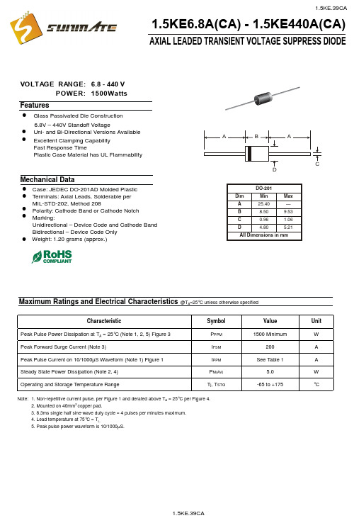
POWER: 1500Wa t VOLTAGE RANGE: 6.8 - 440 VAXIAL LEADED TRANSIENT VOLTAGE SUPPRESS DIODE1.5KE6.8A(CA) - 1.5KE440A(CA)6.8V – 440V Standoff VoltageCase: JEDEC DO-201AD Molded Plastic FeaturesGlass Passivated Die Construction Uni- and Bi-Directional Versions Available Excellent Clamping Capability Fast Response TimePlastic Case Material has UL FlammabilityMechanical DataTerminals: Axial Leads, Solderable per MIL-STD-202, Method 208 Polarity: Cathode Band or Cathode Notch Marking:Unidirectional – Device Code and Cathode Band Bidirectional – Device Code OnlyMaximum Ratings and Electrical Characteristics@T A =25°C unless otherwise specifiedCharacteristicSymbol ValueUnit Peak Pulse Power Dissipation at T A = 25°C (Note 1, 2, 5) Figure 3P PPM 1500 MinimumW Peak Forward Surge Current (Note 3)I FSM 200A Peak Pulse Current on 10/1000µS Waveform (Note 1) Figure 1I PPM See Table 1A Steady State Power Dissipation (Note 2, 4)P M(AV) 5.0W Operating and Storage Temperature RangeT j , T STG-65 to +175°CNote: 1. Non-repetitive current pulse, per Figure 1 and derated above T A = 25°C per Figure 4.2. Mounted on 40mm 2 copper pad.3. 8.3ms single half sine-wave duty cycle = 4 pulses per minutes maximum.4. Lead temperature at 75°C = T L .5. Peak pulse power waveform is 10/1000µS.!!!!!!!Weight: 1.20 grams (approx.)!94.085.57.0211.4510.513.4 1.5KE440CA1.5KE400CA 1.5KE350A 1.5KE220CA 1.5KE170CA 1.5KE150A 1.5KE82CA (uA)R RMW RMW@V leakage Reverse CurrentPulse Peak (A)Vc(V)(mA)BR MAX CurrentMax.BR MIN @I Min.Volgtage Breakdown (V)(BI)(Uni)Voltage Stand-Off Reverse Maximum Clamping V T PP(V)V @I Volgtage Breakdown Test (V)V T Volgtage @I PP 1.5KE62CA 1.5KE56CA 1.5KE51CA 1.5KE47CA 1.5KE43CA 1.5KE39CA 1.5KE36CA 1.5KE33CA 1.5KE30CA 1.5KE27CA 1.5KE24CA 1.5KE22CA 1.5KE20CA 1.5KE18CA 1.5KE16CA 1.5KE15CA 1.5KE13CA 1.5KE12CA 1.5KE11CA 1.5KE10CA 1.5KE9.1CA 1.5KE8.2CA 1.5KE7.5CA 1.5KE6.8CA 1.5KE6.8A 1.5KE7.5A 1.5KE8.2A 1.5KE9.1A 1.5KE10A 1.5KE11A 1.5KE12A 1.5KE13A 1.5KE15A 1.5KE16A 1.5KE18A 1.5KE20A 1.5KE22A 1.5KE24A 1.5KE27A 1.5KE30A 1.5KE33A 1.5KE36A 1.5KE39A 1.5KE43A1.5KE47A 1.5KE51A 1.5KE56A 1.5KE300CA 1.5KE250CA 1.5KE200CA 1.5KE180CA 1.5KE160CA 1.5KE150CA 1.5KE130CA 1.5KE120CA 1.5KE110CA 1.5KE100CA 1.5KE91CA 1.5KE75CA 1.5KE68CA 1.5KE62A 1.5KE68A 1.5KE75A 1.5KE82A 1.5KE91A 1.5KE100A 1.5KE110A 1.5KE120A 1.5KE130A 1.5KE160A 1.5KE170A 1.5KE180A 1.5KE200A 1.5KE220A 1.5KE250A 1.5KE300A 1.5KE400A 1.5KE440A1.5KE350CA 5.80 6.45 7.14 10 144.8 1000.06.407.13 7.88 10 11.3 134.5 500.0 7.79 8.61 10 12.1 125.6 200.0 7.78 8.65 9.55 1.0 113.4 50.0 8.55 9.50 10.5 1.0 14.5 104.8 10.0 9.40 10.11.6 1.0 15.6 97.4 5.0 10.212.6 1.0 16.7 91.0 5.011.1 12.4 13.7 1.0 18.2 83.5 5.0 12.8 14.3 15.8 1.0 21.2 71.75.013.615.2 16.8 1.0 22.5 67.6 5.0 15.3 17.1 18.9 1.0 25.2 60.3 5.0 17.1 19.0 21.0 1.0 27.7 54.9 5.0 18.820.923.1 1.0 30.6 49.7 5.020.5 22.8 25.2 1.0 33.2 45.8 5.023.1 25.7 28.4 1.0 37.5 40.5 5.0 25.6 28.5 31.5 1.0 41.4 36.7 5.0 28.2 31.4 34.7 1.0 45.7 33.3 5.030.8 34.2 37.8 1.0 49.9 30.5 5.033.3 37.1 41.0 1.0 53.9 28.2 5.0 36.8 40.9 45.2 1.0 59.3 25.6 5.0 40.2 44.7 49.4 1.0 64.8 23.5 5.0 43.648.553.6 1.0 70.1 21.7 5.047.8 53.2 58.8 1.0 77.0 19.7 5.053.0 58.9 65.1 1.0 85.0 17.9 5.058.1 64.6 71.4 1.0 92.0 16.5 5.0 64.1 71.3 78.8 1.0 103 14.8 5.0 70.1 77.9 86.1 1.0 113 13.5 5.0 77.8 86.5 95.5 1.0 125 12.2 5.095.0 105 1.0 137 11.1 5.0105 116 1.0 152 10.0 5.0102 114 126 1.0 165 9.2 5.0 111 124 137 1.0 179 8.5 5.0128 143 158 1.0 207 7.3 5.0136 152 168 1.0 219 6.9 5.0 145 162 179 1.0 234 6.5 5.0 154 171 189 1.0 246 6.2 5.0 171 190 210 1.0 274 5.5 5.0 185 209 231 1.0 328 4.6 5.0 214 237 263 1.0 344 4.4 5.0256 285 315 1.0 414 3.7 5.0300 333 368 1.0 482 3.2 5.0 342 380 420 1.0 548 2.8 5.0 376 418 462 1.0 600 2.5 5.0TYPE255075100125150175200100755025T ,AMBIENT TEMPERATURE (°C)Fig.4Pulse Derating CurveA P K P U L S E D E R A T I N G (%P K P W R O R C U R R E N T )25507510012515017520002.55.0T ,LEAD TEMPERATURE (°C)Fig.5,Steady State Power DeratingLP ,S T E A D Y S T A T E P O W E R D I S S I P A T I O N (W )d 0.11.0T ,PULSE WIDTH (µs)Fig.3Pulse Rating Curvep 0.1101001.010100100010000P ,P E A K P U L S E P O W E R (k W )P 0123I ,P E A K P U L S E C U R R E N T (%)P p pt,TIME (ms)Fig.1Pulse Waveform110100100010100100010,000V ,REVERSE STANDOFF VOLTAGE (V)Fig.2Typical Junction CapacitanceRWM C ,C A P A C I T A N C E (p F )j。
1.5KE200A,TVS瞬变二极管中文资料
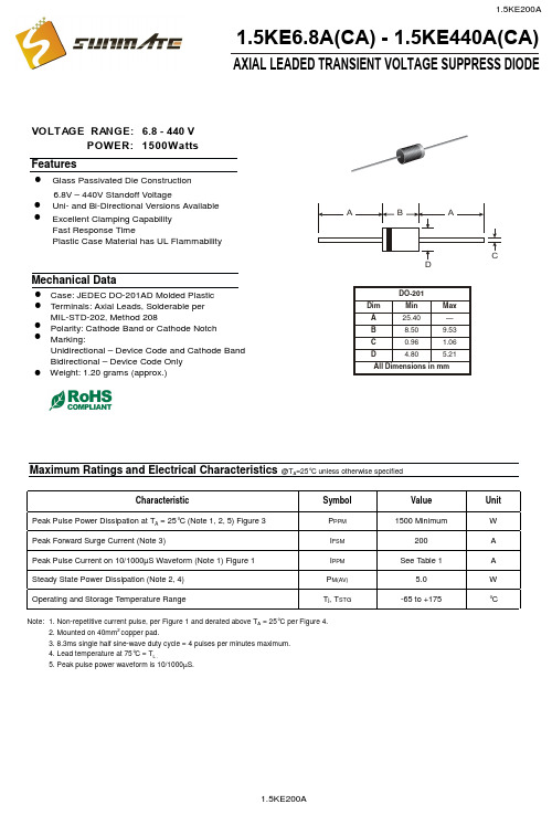
POWER: 1500Wa t VOLTAGE RANGE: 6.8 - 440 VAXIAL LEADED TRANSIENT VOLTAGE SUPPRESS DIODE1.5KE6.8A(CA) - 1.5KE440A(CA)6.8V – 440V Standoff VoltageCase: JEDEC DO-201AD Molded Plastic FeaturesGlass Passivated Die Construction Uni- and Bi-Directional Versions Available Excellent Clamping Capability Fast Response TimePlastic Case Material has UL FlammabilityMechanical DataTerminals: Axial Leads, Solderable per MIL-STD-202, Method 208 Polarity: Cathode Band or Cathode Notch Marking:Unidirectional – Device Code and Cathode Band Bidirectional – Device Code OnlyMaximum Ratings and Electrical Characteristics@T A =25°C unless otherwise specifiedCharacteristicSymbol ValueUnit Peak Pulse Power Dissipation at T A = 25°C (Note 1, 2, 5) Figure 3P PPM 1500 MinimumW Peak Forward Surge Current (Note 3)I FSM 200A Peak Pulse Current on 10/1000µS Waveform (Note 1) Figure 1I PPM See Table 1A Steady State Power Dissipation (Note 2, 4)P M(AV) 5.0W Operating and Storage Temperature RangeT j , T STG-65 to +175°CNote: 1. Non-repetitive current pulse, per Figure 1 and derated above T A = 25°C per Figure 4.2. Mounted on 40mm 2 copper pad.3. 8.3ms single half sine-wave duty cycle = 4 pulses per minutes maximum.4. Lead temperature at 75°C = T L .5. Peak pulse power waveform is 10/1000µS.!!!!!!!Weight: 1.20 grams (approx.)!94.085.57.0211.4510.513.4 1.5KE440CA1.5KE400CA 1.5KE350A 1.5KE220CA 1.5KE170CA 1.5KE150A 1.5KE82CA (uA)R RMW RMW@V leakage Reverse CurrentPulse Peak (A)Vc(V)(mA)BR MAX CurrentMax.BR MIN @I Min.Volgtage Breakdown (V)(BI)(Uni)Voltage Stand-Off Reverse Maximum Clamping V T PP(V)V @I Volgtage Breakdown Test (V)V T Volgtage @I PP 1.5KE62CA 1.5KE56CA 1.5KE51CA 1.5KE47CA 1.5KE43CA 1.5KE39CA 1.5KE36CA 1.5KE33CA 1.5KE30CA 1.5KE27CA 1.5KE24CA 1.5KE22CA 1.5KE20CA 1.5KE18CA 1.5KE16CA 1.5KE15CA 1.5KE13CA 1.5KE12CA 1.5KE11CA 1.5KE10CA 1.5KE9.1CA 1.5KE8.2CA 1.5KE7.5CA 1.5KE6.8CA 1.5KE6.8A 1.5KE7.5A 1.5KE8.2A 1.5KE9.1A 1.5KE10A 1.5KE11A 1.5KE12A 1.5KE13A 1.5KE15A 1.5KE16A 1.5KE18A 1.5KE20A 1.5KE22A 1.5KE24A 1.5KE27A 1.5KE30A 1.5KE33A 1.5KE36A 1.5KE39A1.5KE43A 1.5KE47A 1.5KE51A 1.5KE56A 1.5KE300CA 1.5KE250CA 1.5KE200CA 1.5KE180CA 1.5KE160CA 1.5KE150CA 1.5KE130CA 1.5KE120CA 1.5KE110CA 1.5KE100CA 1.5KE91CA 1.5KE75CA 1.5KE68CA 1.5KE62A 1.5KE68A 1.5KE75A 1.5KE82A 1.5KE91A 1.5KE100A 1.5KE110A 1.5KE120A 1.5KE130A 1.5KE160A 1.5KE170A 1.5KE180A 1.5KE200A 1.5KE220A 1.5KE250A 1.5KE300A 1.5KE400A 1.5KE440A1.5KE350CA 5.80 6.45 7.14 10 144.8 1000.06.407.13 7.88 10 11.3 134.5 500.0 7.79 8.61 10 12.1 125.6 200.0 7.78 8.65 9.55 1.0 113.4 50.0 8.55 9.50 10.5 1.0 14.5 104.8 10.0 9.40 10.11.6 1.0 15.6 97.4 5.0 10.212.6 1.0 16.7 91.0 5.011.1 12.4 13.7 1.0 18.2 83.5 5.0 12.8 14.3 15.8 1.0 21.2 71.75.013.615.2 16.8 1.0 22.5 67.6 5.0 15.3 17.1 18.9 1.0 25.2 60.3 5.0 17.1 19.0 21.0 1.0 27.7 54.9 5.0 18.820.923.1 1.0 30.6 49.7 5.020.5 22.8 25.2 1.0 33.2 45.8 5.023.1 25.7 28.4 1.0 37.5 40.5 5.0 25.6 28.5 31.5 1.0 41.4 36.7 5.0 28.2 31.4 34.7 1.0 45.7 33.3 5.030.8 34.2 37.8 1.0 49.9 30.5 5.033.3 37.1 41.0 1.0 53.9 28.2 5.0 36.8 40.9 45.2 1.0 59.3 25.6 5.0 40.2 44.7 49.4 1.0 64.8 23.5 5.0 43.648.553.6 1.0 70.1 21.7 5.047.8 53.2 58.8 1.0 77.0 19.7 5.053.0 58.9 65.1 1.0 85.0 17.9 5.058.1 64.6 71.4 1.0 92.0 16.5 5.0 64.1 71.3 78.8 1.0 103 14.8 5.0 70.1 77.9 86.1 1.0 113 13.5 5.0 77.8 86.5 95.5 1.0 125 12.2 5.095.0 105 1.0 137 11.1 5.0105 116 1.0 152 10.0 5.0102 114 126 1.0 165 9.2 5.0 111 124 137 1.0 179 8.5 5.0128 143 158 1.0 207 7.3 5.0136 152 168 1.0 219 6.9 5.0 145 162 179 1.0 234 6.5 5.0 154 171 189 1.0 246 6.2 5.0 171 190 210 1.0 274 5.5 5.0 185 209 231 1.0 328 4.6 5.0 214 237 263 1.0 344 4.4 5.0256 285 315 1.0 414 3.7 5.0300 333 368 1.0 482 3.2 5.0 342 380 420 1.0 548 2.8 5.0 376 418 462 1.0 600 2.5 5.0TYPE255075100125150175200100755025T ,AMBIENT TEMPERATURE (°C)Fig.4Pulse Derating CurveA P K P U L S E D E R A T I N G (%P K P W R O R C U R R E N T )25507510012515017520002.55.0T ,LEAD TEMPERATURE (°C)Fig.5,Steady State Power DeratingLP ,S T E A D Y S T A T E P O W E R D I S S I P A T I O N (W )d 0.11.0T ,PULSE WIDTH (µs)Fig.3Pulse Rating Curvep 0.1101001.010100100010000P ,P E A K P U L S E P O W E R (k W )P 0123I ,P E A K P U L S E C U R R E N T (%)P p pt,TIME (ms)Fig.1Pulse Waveform110100100010100100010,000V ,REVERSE STANDOFF VOLTAGE (V)Fig.2Typical Junction CapacitanceRWM C ,C A P A C I T A N C E (p F )j。
1.5KE系列瞬态电压抑制二极管(TVS管)
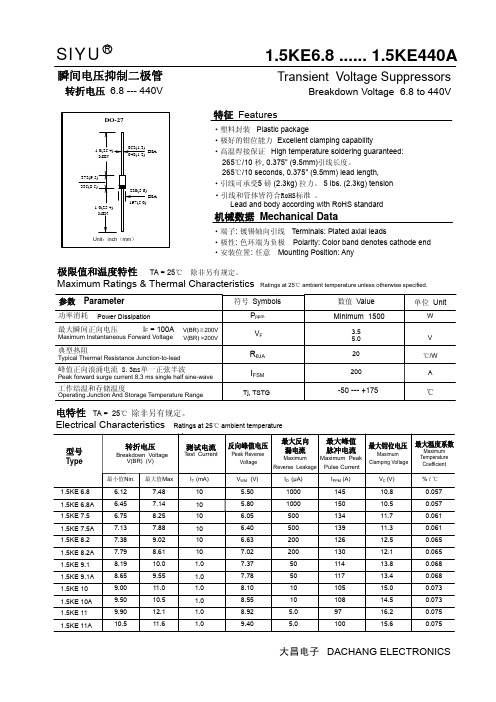
SIYUR1.5KE6.8 ...... 1.5KE440AW 极限值和温度特性 TA = 25℃ 除非另有规定。
Maximum Ratings & Thermal Characteristics Ratings at 25℃ ambient temperature unless otherwise specified.单位 Unit参数 Parameter符号 Symbols数值 Value 功率消耗P ppm Minimum 1500电特性 TA = 25℃ 除非另有规定。
Electrical Characteristics Ratings at 25℃ ambient temperaturePower Dissipation200峰值正向浪涌电流 8.3ms单一正弦半波Peak forward surge current 8.3 ms single half sine-waveAI FSM3.55.0V V F最大瞬间正向电压 I F = 100AMaximum Instantaneous Forward Voltage 20℃/W R θJA 典型热阻Typical Thermal Resistance Junction-to-lead℃Tj, TSTG-50 --- +175工作结温和存储温度Operating Junction And Storage Temperature Range瞬间电压抑制二极管Transient Voltage SuppressorsBreakdown Voltage 6.8 to 440V特征 Features机械数据 Mechanical Data转折电压 6.8 --- 440V·高温焊接保证 High temperature soldering guaranteed:265℃/10 秒, 0.375" (9.5mm)引线长度。
1.5KE300A参数资料

POWER: 1500Wa t VOLTAGE RANGE: 6.8 - 440 VAXIAL LEADED TRANSIENT VOLTAGE SUPPRESS DIODE1.5KE6.8A(CA) - 1.5KE440A(CA)6.8V – 440V Standoff VoltageCase: JEDEC DO-201AD Molded Plastic FeaturesGlass Passivated Die Construction Uni- and Bi-Directional Versions Available Excellent Clamping Capability Fast Response TimePlastic Case Material has UL FlammabilityMechanical DataTerminals: Axial Leads, Solderable per MIL-STD-202, Method 208 Polarity: Cathode Band or Cathode Notch Marking:Unidirectional – Device Code and Cathode Band Bidirectional – Device Code OnlyMaximum Ratings and Electrical Characteristics@T A =25°C unless otherwise specifiedCharacteristicSymbol Value Unit Peak Pulse Power Dissipation at T A = 25°C (Note 1, 2, 5) Figure 3P PPM 1500 MinimumW Peak Forward Surge Current (Note 3)I FSM 200A Peak Pulse Current on 10/1000µS Waveform (Note 1) Figure 1I PPM See Table 1A Steady State Power Dissipation (Note 2, 4)P M(AV) 5.0W Operating and Storage Temperature RangeT j , T STG-65 to +175°CNote: 1. Non-repetitive current pulse, per Figure 1 and derated above T A = 25°C per Figure 4.2. Mounted on 40mm 2 copper pad.3. 8.3ms single half sine-wave duty cycle = 4 pulses per minutes maximum.4. Lead temperature at 75°C = T L .5. Peak pulse power waveform is 10/1000µS.!!!!!!!Weight: 1.20 grams (approx.)!森美特94.085.57.0211.4510.513.4 1.5KE440CA1.5KE400CA 1.5KE350A 1.5KE220CA 1.5KE170CA 1.5KE150A 1.5KE82CA (uA)R RMW RMW@V leakage Reverse CurrentPulse Peak (A)Vc(V)(mA)BR MAX CurrentMax.BR MIN @I Min.Volgtage Breakdown (V)(BI)(Uni)Voltage Stand-Off Reverse Maximum Clamping V T PP(V)V @I Volgtage Breakdown Test (V)V T Volgtage @I PP 1.5KE62CA 1.5KE56CA 1.5KE51CA 1.5KE47CA 1.5KE43CA 1.5KE39CA 1.5KE36CA 1.5KE33CA 1.5KE30CA 1.5KE27CA 1.5KE24CA 1.5KE22CA 1.5KE20CA 1.5KE18CA 1.5KE16CA 1.5KE15CA 1.5KE13CA 1.5KE12CA 1.5KE11CA 1.5KE10CA 1.5KE9.1CA 1.5KE8.2CA 1.5KE7.5CA 1.5KE6.8CA 1.5KE6.8A 1.5KE7.5A 1.5KE8.2A 1.5KE9.1A 1.5KE10A 1.5KE11A 1.5KE12A 1.5KE13A 1.5KE15A 1.5KE16A 1.5KE18A 1.5KE20A 1.5KE22A 1.5KE24A 1.5KE27A 1.5KE30A 1.5KE33A1.5KE36A 1.5KE39A 1.5KE43A 1.5KE47A 1.5KE51A 1.5KE56A 1.5KE300CA 1.5KE250CA 1.5KE200CA 1.5KE180CA 1.5KE160CA 1.5KE150CA 1.5KE130CA 1.5KE120CA 1.5KE110CA 1.5KE100CA 1.5KE91CA 1.5KE75CA 1.5KE68CA 1.5KE62A 1.5KE68A 1.5KE75A 1.5KE82A 1.5KE91A 1.5KE100A 1.5KE110A 1.5KE120A 1.5KE130A 1.5KE160A 1.5KE170A 1.5KE180A 1.5KE200A 1.5KE220A 1.5KE250A 1.5KE300A 1.5KE400A 1.5KE440A1.5KE350CA 5.80 6.45 7.14 10 144.8 1000.06.407.13 7.88 10 11.3 134.5 500.0 7.79 8.61 10 12.1 125.6 200.0 7.78 8.65 9.55 1.0 113.4 50.0 8.55 9.50 10.5 1.0 14.5 104.8 10.0 9.40 10.11.6 1.0 15.6 97.4 5.0 10.212.6 1.0 16.7 91.0 5.011.1 12.4 13.7 1.0 18.2 83.5 5.0 12.8 14.3 15.8 1.0 21.2 71.75.013.615.2 16.8 1.0 22.5 67.6 5.0 15.3 17.1 18.9 1.0 25.2 60.3 5.0 17.1 19.0 21.0 1.0 27.7 54.9 5.0 18.820.923.1 1.0 30.6 49.7 5.020.5 22.8 25.2 1.0 33.2 45.8 5.023.1 25.7 28.4 1.0 37.5 40.5 5.0 25.6 28.5 31.5 1.0 41.4 36.7 5.0 28.2 31.4 34.7 1.0 45.7 33.3 5.030.8 34.2 37.8 1.0 49.9 30.5 5.033.3 37.1 41.0 1.0 53.9 28.2 5.0 36.8 40.9 45.2 1.0 59.3 25.6 5.0 40.2 44.7 49.4 1.0 64.8 23.5 5.0 43.648.553.6 1.0 70.1 21.7 5.047.8 53.2 58.8 1.0 77.0 19.7 5.053.0 58.9 65.1 1.0 85.0 17.9 5.058.1 64.6 71.4 1.0 92.0 16.5 5.0 64.1 71.3 78.8 1.0 103 14.8 5.0 70.1 77.9 86.1 1.0 113 13.5 5.0 77.8 86.5 95.5 1.0 125 12.2 5.095.0 105 1.0 137 11.1 5.0105 116 1.0 152 10.0 5.0102 114 126 1.0 165 9.2 5.0 111 124 137 1.0 179 8.5 5.0128 143 158 1.0 207 7.3 5.0136 152 168 1.0 219 6.9 5.0 145 162 179 1.0 234 6.5 5.0 154 171 189 1.0 246 6.2 5.0 171 190 210 1.0 274 5.5 5.0 185 209 231 1.0 328 4.6 5.0 214 237 263 1.0 344 4.4 5.0256 285 315 1.0 414 3.7 5.0300 333 368 1.0 482 3.2 5.0 342 380 420 1.0 548 2.8 5.0 376 418 462 1.0 600 2.5 5.0TYPE森美特255075100125150175200100755025T ,AMBIENT TEMPERATURE (°C)Fig.4Pulse Derating CurveA P K P U L S E D E R A T I N G (%P K P W R O R C U R R E N T )25507510012515017520002.55.0T ,LEAD TEMPERATURE (°C)Fig.5,Steady State Power DeratingLP ,S T E A D Y S T A T E P O W E R D I S S I P A T I O N (W )d 0.11.0T ,PULSE WIDTH (µs)Fig.3Pulse Rating Curvep 0.1101001.010100100010000P ,P E A K P U L S E P O W E R (k W )P0123I ,P E A K P U L S E C U R R E N T (%)P p pt,TIME (ms)Fig.1Pulse Waveform110100100010100100010,000V ,REVERSE STANDOFF VOLTAGE (V)Fig.2Typical Junction CapacitanceRWM C ,C A P A C I T A N C E (p F )j 森美特。
1.5KE440A参数资料
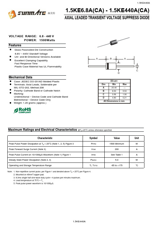
POWER: 1500Wa t VOLTAGE RANGE: 6.8 - 440 VAXIAL LEADED TRANSIENT VOLTAGE SUPPRESS DIODE1.5KE6.8A(CA) - 1.5KE440A(CA)6.8V – 440V Standoff VoltageCase: JEDEC DO-201AD Molded Plastic FeaturesGlass Passivated Die Construction Uni- and Bi-Directional Versions Available Excellent Clamping Capability Fast Response TimePlastic Case Material has UL FlammabilityMechanical DataTerminals: Axial Leads, Solderable per MIL-STD-202, Method 208 Polarity: Cathode Band or Cathode Notch Marking:Unidirectional – Device Code and Cathode Band Bidirectional – Device Code OnlyMaximum Ratings and Electrical Characteristics@T A =25°C unless otherwise specifiedCharacteristicSymbol Value Unit Peak Pulse Power Dissipation at T A = 25°C (Note 1, 2, 5) Figure 3P PPM 1500 MinimumW Peak Forward Surge Current (Note 3)I FSM 200A Peak Pulse Current on 10/1000µS Waveform (Note 1) Figure 1I PPM See Table 1A Steady State Power Dissipation (Note 2, 4)P M(AV) 5.0W Operating and Storage Temperature RangeT j , T STG-65 to +175°CNote: 1. Non-repetitive current pulse, per Figure 1 and derated above T A = 25°C per Figure 4.2. Mounted on 40mm 2 copper pad.3. 8.3ms single half sine-wave duty cycle = 4 pulses per minutes maximum.4. Lead temperature at 75°C = T L .5. Peak pulse power waveform is 10/1000µS.!!!!!!!Weight: 1.20 grams (approx.)!森美特94.085.57.0211.4510.513.4 1.5KE440CA1.5KE400CA 1.5KE350A 1.5KE220CA 1.5KE170CA 1.5KE150A 1.5KE82CA (uA)R RMW RMW@V leakage Reverse CurrentPulse Peak (A)Vc(V)(mA)BR MAX CurrentMax.BR MIN @I Min.Volgtage Breakdown (V)(BI)(Uni)Voltage Stand-Off Reverse Maximum Clamping V T PP(V)V @I Volgtage Breakdown Test (V)V T Volgtage @I PP 1.5KE62CA 1.5KE56CA 1.5KE51CA 1.5KE47CA 1.5KE43CA 1.5KE39CA 1.5KE36CA 1.5KE33CA 1.5KE30CA 1.5KE27CA 1.5KE24CA 1.5KE22CA 1.5KE20CA 1.5KE18CA 1.5KE16CA 1.5KE15CA 1.5KE13CA 1.5KE12CA 1.5KE11CA 1.5KE10CA 1.5KE9.1CA 1.5KE8.2CA 1.5KE7.5CA 1.5KE6.8CA 1.5KE6.8A 1.5KE7.5A 1.5KE8.2A 1.5KE9.1A 1.5KE10A 1.5KE11A 1.5KE12A 1.5KE13A 1.5KE15A 1.5KE16A 1.5KE18A 1.5KE20A 1.5KE22A 1.5KE24A 1.5KE27A 1.5KE30A 1.5KE33A1.5KE36A 1.5KE39A 1.5KE43A 1.5KE47A 1.5KE51A 1.5KE56A 1.5KE300CA 1.5KE250CA 1.5KE200CA 1.5KE180CA 1.5KE160CA 1.5KE150CA 1.5KE130CA 1.5KE120CA 1.5KE110CA 1.5KE100CA 1.5KE91CA 1.5KE75CA 1.5KE68CA 1.5KE62A 1.5KE68A 1.5KE75A 1.5KE82A 1.5KE91A 1.5KE100A 1.5KE110A 1.5KE120A 1.5KE130A 1.5KE160A 1.5KE170A 1.5KE180A 1.5KE200A 1.5KE220A 1.5KE250A 1.5KE300A 1.5KE400A 1.5KE440A1.5KE350CA 5.80 6.45 7.14 10 144.8 1000.06.407.13 7.88 10 11.3 134.5 500.0 7.79 8.61 10 12.1 125.6 200.0 7.78 8.65 9.55 1.0 113.4 50.0 8.55 9.50 10.5 1.0 14.5 104.8 10.0 9.40 10.11.6 1.0 15.6 97.4 5.0 10.212.6 1.0 16.7 91.0 5.011.1 12.4 13.7 1.0 18.2 83.5 5.0 12.8 14.3 15.8 1.0 21.2 71.75.013.615.2 16.8 1.0 22.5 67.6 5.0 15.3 17.1 18.9 1.0 25.2 60.3 5.0 17.1 19.0 21.0 1.0 27.7 54.9 5.0 18.820.923.1 1.0 30.6 49.7 5.020.5 22.8 25.2 1.0 33.2 45.8 5.023.1 25.7 28.4 1.0 37.5 40.5 5.0 25.6 28.5 31.5 1.0 41.4 36.7 5.0 28.2 31.4 34.7 1.0 45.7 33.3 5.030.8 34.2 37.8 1.0 49.9 30.5 5.033.3 37.1 41.0 1.0 53.9 28.2 5.0 36.8 40.9 45.2 1.0 59.3 25.6 5.0 40.2 44.7 49.4 1.0 64.8 23.5 5.0 43.648.553.6 1.0 70.1 21.7 5.047.8 53.2 58.8 1.0 77.0 19.7 5.053.0 58.9 65.1 1.0 85.0 17.9 5.058.1 64.6 71.4 1.0 92.0 16.5 5.0 64.1 71.3 78.8 1.0 103 14.8 5.0 70.1 77.9 86.1 1.0 113 13.5 5.0 77.8 86.5 95.5 1.0 125 12.2 5.095.0 105 1.0 137 11.1 5.0105 116 1.0 152 10.0 5.0102 114 126 1.0 165 9.2 5.0 111 124 137 1.0 179 8.5 5.0128 143 158 1.0 207 7.3 5.0136 152 168 1.0 219 6.9 5.0 145 162 179 1.0 234 6.5 5.0 154 171 189 1.0 246 6.2 5.0 171 190 210 1.0 274 5.5 5.0 185 209 231 1.0 328 4.6 5.0 214 237 263 1.0 344 4.4 5.0256 285 315 1.0 414 3.7 5.0300 333 368 1.0 482 3.2 5.0 342 380 420 1.0 548 2.8 5.0 376 418 462 1.0 600 2.5 5.0TYPE森美特255075100125150175200100755025T ,AMBIENT TEMPERATURE (°C)Fig.4Pulse Derating CurveA P K P U L S E D E R A T I N G (%P K P W R O R C U R R E N T )25507510012515017520002.55.0T ,LEAD TEMPERATURE (°C)Fig.5,Steady State Power DeratingLP ,S T E A D Y S T A T E P O W E R D I S S I P A T I O N (W )d 0.11.0T ,PULSE WIDTH (µs)Fig.3Pulse Rating Curvep 0.1101001.010100100010000P ,P E A K P U L S E P O W E R (k W )P0123I ,P E A K P U L S E C U R R E N T (%)P p pt,TIME (ms)Fig.1Pulse Waveform110100100010100100010,000V ,REVERSE STANDOFF VOLTAGE (V)Fig.2Typical Junction CapacitanceRWM C ,C A P A C I T A N C E (p F )j 森美特。
1.5KE440CA,TVS瞬变二极管中文资料
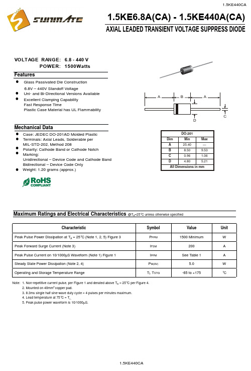
POWER: 1500Wa t VOLTAGE RANGE: 6.8 - 440 VAXIAL LEADED TRANSIENT VOLTAGE SUPPRESS DIODE1.5KE6.8A(CA) - 1.5KE440A(CA)6.8V – 440V Standoff VoltageCase: JEDEC DO-201AD Molded Plastic FeaturesGlass Passivated Die Construction Uni- and Bi-Directional Versions Available Excellent Clamping Capability Fast Response TimePlastic Case Material has UL FlammabilityMechanical DataTerminals: Axial Leads, Solderable per MIL-STD-202, Method 208 Polarity: Cathode Band or Cathode Notch Marking:Unidirectional – Device Code and Cathode Band Bidirectional – Device Code OnlyMaximum Ratings and Electrical Characteristics@T A =25°C unless otherwise specifiedCharacteristicSymbol ValueUnit Peak Pulse Power Dissipation at T A = 25°C (Note 1, 2, 5) Figure 3P PPM 1500 MinimumW Peak Forward Surge Current (Note 3)I FSM 200A Peak Pulse Current on 10/1000µS Waveform (Note 1) Figure 1I PPM See Table 1A Steady State Power Dissipation (Note 2, 4)P M(AV) 5.0W Operating and Storage Temperature RangeT j , T STG-65 to +175°CNote: 1. Non-repetitive current pulse, per Figure 1 and derated above T A = 25°C per Figure 4.2. Mounted on 40mm 2 copper pad.3. 8.3ms single half sine-wave duty cycle = 4 pulses per minutes maximum.4. Lead temperature at 75°C = T L .5. Peak pulse power waveform is 10/1000µS.!!!!!!!Weight: 1.20 grams (approx.)!94.085.57.0211.4510.513.4 1.5KE440CA1.5KE400CA 1.5KE350A 1.5KE220CA 1.5KE170CA 1.5KE150A 1.5KE82CA (uA)R RMW RMW@V leakage Reverse CurrentPulse Peak (A)Vc(V)(mA)BR MAX CurrentMax.BR MIN @I Min.Volgtage Breakdown (V)(BI)(Uni)Voltage Stand-Off Reverse Maximum Clamping V T PP(V)V @I Volgtage Breakdown Test (V)V T Volgtage @I PP 1.5KE62CA 1.5KE56CA 1.5KE51CA 1.5KE47CA 1.5KE43CA 1.5KE39CA 1.5KE36CA 1.5KE33CA 1.5KE30CA 1.5KE27CA 1.5KE24CA 1.5KE22CA 1.5KE20CA 1.5KE18CA 1.5KE16CA 1.5KE15CA 1.5KE13CA 1.5KE12CA 1.5KE11CA 1.5KE10CA 1.5KE9.1CA 1.5KE8.2CA 1.5KE7.5CA 1.5KE6.8CA 1.5KE6.8A 1.5KE7.5A 1.5KE8.2A 1.5KE9.1A 1.5KE10A 1.5KE11A 1.5KE12A 1.5KE13A 1.5KE15A 1.5KE16A 1.5KE18A 1.5KE20A 1.5KE22A 1.5KE24A 1.5KE27A 1.5KE30A 1.5KE33A 1.5KE36A 1.5KE39A1.5KE43A 1.5KE47A 1.5KE51A 1.5KE56A 1.5KE300CA 1.5KE250CA 1.5KE200CA 1.5KE180CA 1.5KE160CA 1.5KE150CA 1.5KE130CA 1.5KE120CA 1.5KE110CA 1.5KE100CA 1.5KE91CA 1.5KE75CA 1.5KE68CA 1.5KE62A 1.5KE68A 1.5KE75A 1.5KE82A 1.5KE91A 1.5KE100A 1.5KE110A 1.5KE120A 1.5KE130A 1.5KE160A 1.5KE170A 1.5KE180A 1.5KE200A 1.5KE220A 1.5KE250A 1.5KE300A 1.5KE400A 1.5KE440A1.5KE350CA 5.80 6.45 7.14 10 144.8 1000.06.407.13 7.88 10 11.3 134.5 500.0 7.79 8.61 10 12.1 125.6 200.0 7.78 8.65 9.55 1.0 113.4 50.0 8.55 9.50 10.5 1.0 14.5 104.8 10.0 9.40 10.11.6 1.0 15.6 97.4 5.0 10.212.6 1.0 16.7 91.0 5.011.1 12.4 13.7 1.0 18.2 83.5 5.0 12.8 14.3 15.8 1.0 21.2 71.75.013.615.2 16.8 1.0 22.5 67.6 5.0 15.3 17.1 18.9 1.0 25.2 60.3 5.0 17.1 19.0 21.0 1.0 27.7 54.9 5.0 18.820.923.1 1.0 30.6 49.7 5.020.5 22.8 25.2 1.0 33.2 45.8 5.023.1 25.7 28.4 1.0 37.5 40.5 5.0 25.6 28.5 31.5 1.0 41.4 36.7 5.0 28.2 31.4 34.7 1.0 45.7 33.3 5.030.8 34.2 37.8 1.0 49.9 30.5 5.033.3 37.1 41.0 1.0 53.9 28.2 5.0 36.8 40.9 45.2 1.0 59.3 25.6 5.0 40.2 44.7 49.4 1.0 64.8 23.5 5.0 43.648.553.6 1.0 70.1 21.7 5.047.8 53.2 58.8 1.0 77.0 19.7 5.053.0 58.9 65.1 1.0 85.0 17.9 5.058.1 64.6 71.4 1.0 92.0 16.5 5.0 64.1 71.3 78.8 1.0 103 14.8 5.0 70.1 77.9 86.1 1.0 113 13.5 5.0 77.8 86.5 95.5 1.0 125 12.2 5.095.0 105 1.0 137 11.1 5.0105 116 1.0 152 10.0 5.0102 114 126 1.0 165 9.2 5.0 111 124 137 1.0 179 8.5 5.0128 143 158 1.0 207 7.3 5.0136 152 168 1.0 219 6.9 5.0 145 162 179 1.0 234 6.5 5.0 154 171 189 1.0 246 6.2 5.0 171 190 210 1.0 274 5.5 5.0 185 209 231 1.0 328 4.6 5.0 214 237 263 1.0 344 4.4 5.0256 285 315 1.0 414 3.7 5.0300 333 368 1.0 482 3.2 5.0 342 380 420 1.0 548 2.8 5.0 376 418 462 1.0 600 2.5 5.0TYPE255075100125150175200100755025T ,AMBIENT TEMPERATURE (°C)Fig.4Pulse Derating CurveA P K P U L S E D E R A T I N G (%P K P W R O R C U R R E N T )25507510012515017520002.55.0T ,LEAD TEMPERATURE (°C)Fig.5,Steady State Power DeratingLP ,S T E A D Y S T A T E P O W E R D I S S I P A T I O N (W )d 0.11.0T ,PULSE WIDTH (µs)Fig.3Pulse Rating Curvep 0.1101001.010100100010000P ,P E A K P U L S E P O W E R (k W )P 0123I ,P E A K P U L S E C U R R E N T (%)P p pt,TIME (ms)Fig.1Pulse Waveform110100100010100100010,000V ,REVERSE STANDOFF VOLTAGE (V)Fig.2Typical Junction CapacitanceRWM C ,C A P A C I T A N C E (p F )j。
通孔插装元器件焊孔、焊盘设计工艺规范
通孔插装元器件焊孔、焊盘设计工艺规范WI-EN-***版本:A/0分发号:编制:审核:批准:日期:1.0目的:规范元器件焊孔、焊盘设计,满足可制造性要求。
2.0 适用范围:通孔插装元器件的焊孔、焊盘设计。3.0 内容 3.1 定义3.1.1引脚直径:若无特殊说明,指圆形引脚的直径,或者指方形(含扁形)引脚截面的对角线长度,用d 表示,如图3.1.1(a )、图3.1.1(b )所示。
3.1.2 方形(或扁形)引脚截面尺寸:用w 表示引脚宽度,用t 表示引脚厚度,如图3.1.1(b )所示。
当方形引脚的宽厚比w/t 大于2时称为扁形引脚。
3.1.3 焊孔直径:圆形焊孔直径,用d1表示,如图3.1.1(c )所示。
3.1.4 焊盘直径:圆形焊盘直径,用D 表示,如图3.1.1(c )所示。
3.1.5 椭圆(或方形)焊盘长度:用L 表示,如图3.1.1(d )所示。
3.1.6 椭圆(或方形)焊盘宽度:用W 表示,如图3.1.1(d )所示。
3.2 焊孔3.2.1一般情况下,焊孔直径d1按表3.2.1选取:图3.1.1(a) 圆形引脚元器件(b) 方形(或扁形)引脚元器件元件(c) 圆形焊孔及焊盘(d) 圆形焊孔及椭圆(或方形)焊盘表3.2.1面板取下限。
注2:在仅有有限的几个插装元件,多数元件为贴装元件的情况下,有可能使用到 通孔回流焊工艺,比如模块针脚的焊接。
3.2.2脚距精度较高,且定位要求也较高的元器件,如输入、输出插座等,焊孔直径等于引脚直径加上0.15~0.2mm 。
3.2.3 方形引脚焊孔:3.2.3.1 w >2.5mm 时,设计为方焊孔(圆角R 为0.3~0.35mm,防止圆角影响插装),方焊孔尺寸如图3.2.3.1所示。
3.2.3.2 w <2 mm 时,设计为圆孔,焊孔直径d1=d+0.15~0.25mm, d 为引脚截面对角线长。
3.2.4扁形引脚焊孔:3.2.4.1 w <1.8mm 时,设计成圆孔,焊孔直径d1=d+0.15~0.25mm, d 为引脚截面对角线长。
- 1、下载文档前请自行甄别文档内容的完整性,平台不提供额外的编辑、内容补充、找答案等附加服务。
- 2、"仅部分预览"的文档,不可在线预览部分如存在完整性等问题,可反馈申请退款(可完整预览的文档不适用该条件!)。
- 3、如文档侵犯您的权益,请联系客服反馈,我们会尽快为您处理(人工客服工作时间:9:00-18:30)。
1/6TRANSIL TMsPEAK PULSE POWER :1500W (10/1000µs)sBREAKDOWN VOLTAGE RANGE :From 6.8V to 440VsUNI AND BIDIRECTIONAL TYPES sLOW CLAMPING FACTOR sFAST RESPONSE TIME sUL RECOGNIZEDFEATURESSymbol ParameterValue Unit P PP Peak pulse power dissipation (see note 1)Tj initial =T amb 1500W P Power dissipation on infinite heatsink T amb =75°C 5W I FSM Non repetitive surge peak forward current for unidirectional types tp =10msTj initial =T amb200A T stg T j Storage temperature range Maximum junction temperature-65to +175175°C °C T LMaximum lead temperature for soldering during 10s at 5mm from case230°CNote 1:For a surge greater than the maximum values,the diode will fail in short-circuit.ABSOLUTE MAXIMUM RATINGS (T amb =25°C)DESCRIPTIONTransil diodes provide high overvoltage protection by clamping action.Their instantaneous response to transient overvoltages makes them particularly suited to protect voltage sensitive devices such as MOS Technology and low voltage supplied IC’s.February 2002-Ed:3A Symbol ParameterValue Unit R th (j-l)Junction to leads20°C/W R th (j-a)Junction to ambient on printed circuit.L lead =10mm75°C/WTHERMAL RESISTANCES1.5KExxSymbol ParameterV RM Stand-off voltage V BR Breakdown voltage V CL Clamping voltage I RM Leakage current @V RM I PPPeak pulse currentαTVoltage temperature coefficient V FForward voltage dropELECTRICAL CHARACTERISTICS (T amb =25°C)TypesI RM @V RM V BR @I R V CL @I PP V CL @I PP αTC max min nom maxmax max max typ note210/1000µs 8/20µs note3note4Unidirectional Bidirectional µA V V V V mA VAVA10-4/°C pF 1.5KE6V8A 1.5KE6V8CA 1000 5.8 6.45 6.87.141010.514313.4746 5.795001.5KE7V5A 1.5KE7V5CA 500 6.47.137.57.881011.313214.5690 6.185001.5KE10A 1.5KE10CA 108.559.51010.5114.510018.65387.370001.5KE12A 1.5KE12CA 510.211.41212.6116.79021.74617.860001.5KE15A 1.5KE15CA 112.814.31515.8121.27127.23688.450001.5KE18A 1.5KE18CA 115.317.11818.9125.259.532.53088.843001.5KE22A 1.5KE22CA 118.820.92223.1130.64939.32549.237001.5KE24A 1.5KE24CA 120.522.82425.2133.24542.82349.435001.5KE27A 1.5KE27CA 123.125.72728.4137.54048.32079.632001.5KE30A 1.5KE30CA 125.628.53031.5141.53653.51879.729001.5KE33A 1.5KE33CA 128.231.43334.7145.73359.01699.827001.5KE36A 1.5KE36CA 130.834.23637.8149.93064.31569.925001.5KE39A 1.5KE39CA 133.337.13941.0153.92869.714310.024001.5KE47A 1.5KE47CA 140.244.74749.4164.823.28411910.120501.5KE56A 1.5KE56CA 147.853.25658.817719.510010010.318001.5KE62A 1.5KE62CA 153.058.96265.118517.71119010.417001.5KE68A 1.5KE68CA 158.164.66871.419216.31218310.415501.5KE82A 1.5KE82CA 170.177.98286.1111313.31466910.513501.5KE100A 1.5KE100CA 185.595.01001051137111785610.611501.5KE120A 1.5KE120CA 110211412012611659.12124710.710001.5KE150A 1.5KE150CA 112814315015812077.22653810.88501.5KE180A1.5KE180CA115417118018912466.131731.510.87251.5KExxTypesI RM @V RM V BR @I R V CL @I PP V CL @I PP αTC max min nom maxmax max max typ note210/1000µs 8/20µs note3note4Unidirectional Bidirectional µAV V V V mA V A V A 10-4/°C pF 1.5KE200A 1.5KE200CA 11711902002101274 5.53532810.86751.5KE220A 1.5KE220CA 11882092202311328 4.63882610.86251.5KE250A 1.5KE250CA 12132372502631344 5.044223115601.5KE300A 1.5KE300CA 12562853003151414 5.052919115001.5KE350A 1.5KE350CA 12993323503681482 4.061816114301.5KE400A 1.5KE400CA 13423804004201548 4.070614113901.5KE440A1.5KE440CA137641844046216033.57761311360Note 2:Pulse test:t p <50ms.Note 3:∆V BR =αT *(T amb -25)*V BR (25°C).Note 4:V R =0V,F =1MHz.For bidirectional types,capacitance value is divided by 2.Fig.1:Peak pulse power dissipation versus initial junction temperature (printed circuit%I PP 50t1001.5KExxFig.2:Peak pulse power versus exponential pulse duration.Fig.3:Clamping voltage versus peak pulse current.Exponential waveform:t p =20µs________t p =1ms——————-t p =10ms ...............Note :The curves of the figure 3are specified for a junction temperature of 25°C before surge.The given results may be extrapolated for other junction temperatures by using the following formula :∆V BR =αT*(T amb -25)*V BR (25°C).For intermediate voltages,extrapolate the given results.1.5KExxFig.6:Transient thermal impedance junc-tion-ambient versus pulse duration (For FR4PC Board with L lead =10mm).Fig.5:Peak forward voltage drop versus peak forward current (typical values for unidirectional types).Note :Multiply by 2for units with V BR >220V.Fig.4b :Capacitance versus reverse applied voltage for bidirectional types (typical values).Fig.4a :Capacitance versus reverse applied voltage for unidirectional types (typical values).Fig.7:Relative variation of leakage current versus junction temperature.1.5KExxPackaging :standard packaging is in tape and reel.PACKAGE MECHANICAL DATA DO-201(Plastic)ORDER CODEWeight =0.876g.MARKING :Logo,Date Code,Type Code,Cathode Band (for unidirectional types only).Information furnished is believed to be accurate and reliable.However,STMicroelectronics assumes no responsibility for the consequences of use of such information nor for any infringement of patents or other rights of third parties which may result from its use.No license is granted by implication or otherwise under any patent or patent rights of STMicroelectronics.Specifications mentioned in this publication are subject to change without notice.This publication supersedes and replaces all information previously supplied.STMicroelectronics products are not authorized for use as critical components in life support devices or systems without express written approval of STMicroelectronics.The ST logo is a registered trademark of STMicroelectronics ©2003STMicroelectronics -Printed in Italy -All rights reserved.STMicroelectronics GROUP OF COMPANIESAustralia -Brazil -Canada -China -Finland -France -GermanyHong Kong -India -Israel -Italy -Japan -Malaysia -Malta -Morocco -SingaporeSpain -Sweden -Switzerland -United Kingdom -United States.。
