Cllx3_
BUB-JOL 电子产品说明书
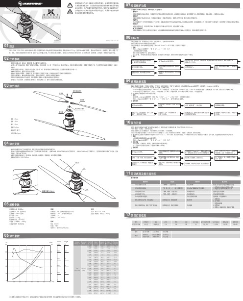
01简介20230609CM-H11M-11122-70KV 共轴无刷动力系统是一款适配单轴25-28kg负载的行业版动力系统,单轴最大拉力57.5 kg;适配50mm碳纤管机臂, 整体防护等级IP45,高效散热,专为大载重、消防、物流、应急等领域多旋翼无人机应用,提供一站式动力解决方案。
FOC电调采用CAN通讯,数字油门与PWM油门双冗余设计,具备上电自检,故障存储,过流保护,堵转保护等保护功能。
0203动力组成04动力安装运行DataLink软件。
先选择“扫描”按键,再给电调通电。
等待升级完成,若升级失败,请重复前部分操作。
设备断电,断电无先后顺序,不会烧坏设备。
电调CAN线连接到DataLink数据盒子上,数据盒子连接到电脑。
进入CAN调参页面。
查看页面提示,确认设置是否成功。
设备断电,断电无先后顺序,亦不会烧坏设备。
CM-H11M-11122-70KV使用说明书法使用。
·所含电调拥有CAN功能,在使用CAN功能时,同一架飞机,电调ID和油门通道不能相同,否则多电调会被识别为同一个。
·地面测试请勿带桨,避免带来不必要的危险。
·请务必仔细连接好各部件,若接触不良,您可能无法正常控制飞行器,或出现设备损坏等其他不可预知的情况。
·若需对电调的输入、输出线插头做相关焊接,请保证焊接牢靠,并使用足功率的焊接设备。
·勿在外部环境温度超过65℃时使用,高温将会毁坏电调并且可能导致电机损害造成炸机。
·动力套出厂已定好转向,请观察电机转向标示,因封装密封工艺,暂不支持更改电机相线顺序。
使用环境温度:-30℃-65℃总重量(不含桨叶):4350g支持油门频率:50-500Hz电 机型号:11122KV值:70KV电机尺寸:Φ120.1 x 55.2mm在无要求的情况下,电调默认出厂ID为1,油门通道为1,总线速率为500KHz。
此功能需要另购DataLink数据盒子才能使用。
MAGLINK LX 控制台手册说明书
INSTALLATION MANUAL CONSOLE MAGLINK LXINDEXREVISION INDEX (2)INTRODUCTION (3)GENERAL WARNINGS (3)DESCRIPTION (4)COMPATIBLE PROBES MODEL LIST (4)INSTALLATION (5)MAIN COMPONENTS (6)PROBES CONNECTIONS (8)MAGLINK LX SLAVE CONNECTORS (9)CONSOLE VIA RS232 HOST CONNECTION (10)MANAGEMENT SYSTEMS COMMON CONNECTION (11)PROGRAM DESCRIPTION (12)MANUAL UPDATE PROCEDURE (18)SEND LOG INFORMATION FOR SUPPORT (18)STOCK PRINTOUT (19)SHIFT REPORT (19)EXTERNAL DISCONNECTION EQUIPMENT (20)SAFETY INSTRUCTIONS (20)PRODUCT LABEL (21)CERTIFICATION (22)NOTIFICATION (26)REVISION INDEXINTRODUCTIONThe handbook gives all the instructions for installation and use of Maglink LX console.GENERAL WARNINGS∙Please read carefully the instructions given in this handbook before working on this equipment.∙The manufacture is not responsible of any operation performed not mentioned in this handbook.∙In case of failure or faulty operations, please refer to authorized people in charge for maintenance or directly to the manufacturer.∙The manufacturer refuses all responsibility for any eventual injury and/or damage to things caused by the missing observation of safety requirements.∙The assigned personnel is required to know all the safety requirements relative to this equipment.∙In case of doubts about functioning of the equipment please refer to authorized people for maintenance or directly to the manufacturer.∙Every tampering of the equipment relieves the manufacturer from any responsibility in front of competent authorities.This product is used in fuel tanks and in hazardous areas for risk of explosion and fire. Subterranean leakage of fuel tanks may cause serious damages to environment and people injury.Improper use, not in accordance with the requirements, may affect the safety of the productThis product complies with EU Directive 2002/96/EC.The crossed-bin symbol on the device indicates that the product, at the end of its lifecycle, should be disposed separately from household waste, must be brought to an electrical and electronic equipment collection point.DESCRIPTIONConsole for monitoring level gauge and tanks alarms. Bus management up to 32 probes, 16 ON-OFF sensors, 4 slave displays, 2 channel each, 4 integrated relays and other 16 relays on the bus with outputs and programmable events, 20 relays in total. Can be interfaced with the major management systems located in petrol stations.COMPATIBLE PROBES MODEL LISTThe following probes models can be connected to MAGLINK LX console:∙XMT EXD 485 polling mode∙XMT SI 485 polling mode∙XMT SI RF∙XLR SI 485 polling modeAnd auxiliary equipment:∙Slave relay boards∙Local or remote printer∙Reed sensorsINSTALLATION∙If mixed with air, the flammable vapors may cause explosion. Hazardous areas may be originated therefore by the presence of gas or vapors.∙Explosions or fires may cause damage, even lethal.∙This console is not explosion proof.∙Do not install the console in hazardous area.∙Use only fuse 250V – 1A on input power supplyINSTALLATION SITERegarding the installation site, it is necessary to consider that the console must be protected against vibrations and extreme climatic conditions (in particular high/low temperatures, humidity, etc.) which may damage the electrical circuits. Please be sure to install in an area protected from humidity and sprinkles of water.220Vac ELECTRICAL CONNECTIONTo realize the electrical connection please proceed as follow:∙Switch off all the power switches on the electrical board panel.∙Connect between board panel and the console using the appropriate connectors.∙To connect driving force, please use cable with 3 wires whose section is at least 1.5 mm2 (phase, neutral, earth) adequately protected. Supply cable must be approved according to standards IEC 60227 or IEC 60245∙Be sure that the power plug used has ground round connection and that there is a protection device acting against short circuits and overloads.∙The power cable must be always easy recognizable and reachable since it has disconnecting function too.Regarding probes connection, plea se refer to chapter “Probes connection”.∙There is high voltage into the console which may be lethal.∙The equipment installed in hazardous areas shall be explosion-proof or intrinsically safe according to the degree of protection required.INSTALLATION PROCEDUREFix the console to the wall using the holes on the plastic enclosure. To fix the console to the wall use bolt sleeves.Bottom side.PRODUCT CLEANINGFor product cleaning must be used a cloth dampened only with water and common detergents non aggressive without use of any acids, chemical solvents or organic substances.MAIN COMPONENTSPower supply, intrinsically safe barrier and main boardCONNECTION TO INTRINSICALLY SAFE PROBES MODEL XMT-SI-485 TO BARRIER MODEL BRA-2SIPIf sensors to be connected are more than 16, n. 2 BRA-2SIP are installed and additional external barriers must be used since one barrier can supply up to 8 sensors only.Maglink LX rev.06 2015-07 - ENG PROBES CONNECTIONSMAGLINK LX SLAVE CONNECTORSCONSOLE VIA RS232 HOST CONNECTIONFor distances up to 15mt the remote connection between MAGLINK LX and host can be done using serial link RS232C as per the indications given but the system to which it is connected.USBRJ45used to connect MagLink LX to local network for web access configuration (WebConfig). If you connect directly to other computer remember to use a cross cable.RS232 PORT 1For software management host connection, printer connectionRS232 PORT 2MANAGEMENT SYSTEMS COMMON CONNECTIONMAGLINK LX can be connected to several management systems (PIGNONE; GILBARCO; TOKHEIM; DRESSER; Probe Emulation; DIALOG; RETALIX; DOMS; ORPAK; TOREX; TLG-SMITHS).ES:DRESSER WAYNE SINP:CONSOLE SYSTEMPIN 2 > PIN 2PIN 3 > PIN 3PIN 5 > PIN 5TOKHEIM and DIALOG:CONSOLE SYSTEMPIN 2 > PIN 2PIN 3 > PIN 3PIN 5 > PIN 5PIN 4 > PIN 6----------------------------------------------------------------------------------------------------------------------------GILBARCO Passport Europe (9600 O71):CONSOLE SYSTEMPIN 2 > PIN 8PIN 3 > PIN 1PIN 5 > PIN 4DOMS (9600 E71)DIALOG (1200 N81)TOREX (2400 E71)PROGRAM DESCRIPTIONThe console is provided with a Qt application that handles all fundamental values for optimal tank management.The application is very easy and user friendly. It has a sort of circular menu from which the user can navigate through all available functions. The application first page is the following:In this page it’s summarized all main tank information. At the very top you’ll find configured tank list. The page can contain a maximum of 4 tanks, if you want to see other tanks you must click on the big red right/left arrow button that you find at the right/left edge of the touch screen.Console functions are accessible by clicking up/down red arrow button that you find near the top left corner and bottom left corner of the touch screen. Use these up/down arrows button to navigate through all console function as shown below:Tank summery with percentage tank load.Alarm log.To acknowledge active alarms click on the ACK button to the right of the alarm table.List fuel represents the tank, fuel, meter configuration for those who have dispensing system connected to the console. To access detail tank information you can either click on the tank number or directly on the tank image.Detail tank view. Alarms are graphically reported beside the green level product indicator.Tank configuration settings.History listDelivery listDiagnostic pageDaily reconciliation tableFuel list is the configuration between tanks and dispensers and noozles.MANUAL UPDATE PROCEDUREThe console software can and should be updated periodically. The application latest version files can be downloaded in zip format from www.startitaliana.it site MagLink-LX section.To update the console application and the web application follow the steps:∙Download the zip file with the latest version∙Take an usb pen drive with at least 50MB of free space∙BE SURE THE USB PEN DRIVE IS FAT32 FORMATTED∙From usb pen drive create from root lx-update folder∙Connect the usb pen drive to the computer and unzip the content of the downloaded file in to newly created folder lx-update ∙Connect the usb pen drive to the console∙Click on the Info button to access info page∙Wait until Usb download button appears and press the button to copy all updated files to the console newversion folder ∙Now press Update button to complete update procedure∙Most of the times the console will reboot nor the application will be reloadedSEND LOG INFORMATION FOR SUPPORTIn case of issues the best solution is to connect the console to the internet. Rout e the console private IP address to user’s public IP address, open port 22 for console access, and port 80 for web access.When internet connection is not available for any reason user must provide to StartItaliana all information needed for debug process. This is done by pressing Info button to access info page then follow the steps:∙Take an usb pen drive with at least 50MB of free space∙BE SURE THE USB PEN DRIVE IS FAT32 FORMATTED∙Connect the usb pen drive to the console∙Click on the Info button to access info page∙Wait until Export log button appears and press the button to start copy process, all required files will be copied to the console lx-support folder∙Zip the lx-support*************************************************STOCK PRINTOUTConsole can be provided with Sprint printer that must be connected to RS232 com1 serial port. When the printer is connected user can print current stock, this means total product for each tank, summary product stock group by product type.To proceed with the printout, click on Info button to access the info page and then click on Print situation button, wait until the ticket printer comes out.SHIFT REPORTConsole can manage shift reports. To open/close shifts just follow the instructions below.To proceed with the shift report, click on Info button to access the info page and then click on Set shift report button and confirm the following message box. This operation will close current shift and open next one.You can navigate through the tank dedicated pages and view the daily shift report:EXTERNAL DISCONNECTION EQUIPMENTInstall an external magneto thermal breaker, approved by the standards IEC 60947-1 and IEC 60947-3, and marked and installed in accordance with clause 6.11 of EN 61010-1. The magneto thermal easily accessible. Used as a device against overcurrent. Characteristic external magneto thermal breaker: 4 A, 230 V~, 2P.SAFETY INSTRUCTIONS“Safety Instruction” attached.Maglink LX rev.06 2015-07 - ENG PRODUCT LABELSTART ITALIANA SRLVia Pola,6 – 20813 Bovisio Masciago (MB) ITALYMAGLINK-LX Serial nr: xxxxxx45VA, 100-240V~, 50/60HzWorking Temperature: -10°C + 50°C0722 CEC 10 ATEX 025 Rev.3II (1) G [Exia] IIBFISCO power supply U m=250V [Exia] IIBMaglink LX rev.06 2015-07 - ENG CERTIFICATIONMaglink LX rev.06 2015-07 - ENGNOTIFICATIONMaglink LX rev.06 2015-07 - ENGSTART ITALIANA S.r.l.Via Pola, 620813 Bovisio Masciago (MB)Tel: +39 0362 – 15.81.465Fax: +39 0362 – 15.81.464。
松下LX3使用技1
松下LX3使用技巧★初学者的LX3设定(新手LX3设置)由于LX3的iA模式拍出来的效果始终不是很好。
因此对新手的设置做些建议:把相机设置在P档,“动态”胶片模式,感光度范围ISO 80-200,平均测光,自动白平衡,P 档为自动曝光模式。
“动态”的拍风景非常好,颜色鲜艳。
如果拍人像用肖像场景模式。
★、其它技巧1.精准的小范围物体曝光准确用:点测光可以让微距更光彩,另外人像拍摄时,也可以对准人物的局部(脸部或眼睛等)进行准确曝光。
适用拍摄用途:舞台摄影,个人艺术照,新闻特写照片等。
2.曝光补偿在实际调节的时候,会使快门速度发生变化。
基于这个原理,我们在一些需要高快门速度的环境中,可以适当地降低EV,从而提高一定的快门速度,是画面清晰有效的避免因为手的抖动而导致的画面模糊。
花花草草比较艳丽,为了保留更多的细节,适当的降低EV会有不错的效果。
3.摄风景照片一般使用光圈优先模式,通过控制光圈获得足够大的景深,使风景照的前景到后景都足够清晰。
想简单地设置,则把模式转盘调到风景模式即可,相机也会做出较为合理的判断。
按下ISO键以设定感光度拍摄风景时尽量使用最低ISO风景照必须重视细节,而且因为放置在三脚架上可以不理会快门速度,按下ISO按键把感光度设置到最低的ISO 100吧。
犹如更换胶片相机用的胶卷种类那样,可从基于六种彩色模式和三种单色模式的丰富选项中任意选用中意的表现模式。
如选用多重胶片模式,每按一次快门键,即可录制最多三幅不同效果1的照片。
★·机器设置技巧此部分摘自春卷的评测报告机背四方向键的下键被设置成FN按键,用户可以自定义按键功能,默认状态下该键的功能是快速回放。
松下LX3可以在通过长按机背上的删除键方式启动取景模式下的视频输出。
√松下LX3夜景迷你三脚架,这组照片大多采用ISO80的最低感光度,相机的光圈则被设置在F4-5.6之间,而快门速度则普遍在1秒以上,个别达到6秒。
请格外注意松下LX3在极低光照条件下色彩表现以及画面明暗层次。
CL6291

CL6291高效率升压DC/DC概述CL6291是一款微小型、高效率、升压型DC/DC 调整器。
电路由电流模PWM 控制环路,误差放大器,斜波补偿电路,比较器和功率开关等模块组成。
该芯片可在较宽负载范围内高效稳定的工作,可以从锂电池供电下直接输出高达12V 的电压,CL6291内置一个2.5A 的MOS 管。
高达93%的转换效率能够高效的延长电池寿命。
可以通过调整两个外加电阻来设定输出电压以及一个外加电阻来设定输出的过流电流阀值,开关频率控制在1.0mHz,有效的为客户节省外围电路成本,同时用23-6的封装还能实现输出短路保护,输出过电压保护和过温保护。
特点◆效率高达93%◆2.6V 输入升压至12V ◆固定工作频率:1MHz ◆输出短路保护◆输出过压保护◆FB 基准电压0.6V◆工作温度-40℃至85℃◆内置软启动功能应用◆传感器◆可穿戴设备◆便携式医疗设备◆电池后备电源CL6291采用SOT-23-6L 封装典型应用电路管脚描述最大额定值(注1)项目符号最大额定值单位输入电压VIN -0.3~6V 输出电压VSW -0.3~16V 耗散功耗PD 250mW 工作环境温度Topr -40~+80℃存储温度Tstg-40~+125℃注1:超出最大范围器件可能损毁。
推荐工作范围内器件可以工作,但不保证其特性。
电气特性表明的直流和交流特性是在特定条件下测得,其特性可以保证。
此特性假定器件在推荐工作范围内工作。
未示出特性不保证其性能。
典型值是最佳性能点。
管脚号管脚名描述1SW 开关引脚。
2GND 接地端。
3FB 电压反馈端4EN 使能端5VIN 输入供电端6ISET输出电流过流点设置,通过外部电阻阻值设定所需要的OCP 点。
I ISET =48000/R ISET结构框图电气特性符号符号说明条件最小值典型值最大值单位V CC输入电压 2.66V Vout输出电压12V Supply Current(Shutdown)关断电流V EN=0V or EN=GND0.11uA V FB反馈基准电压0.5880.60.612V R DSON MOS内阻VIN=3.3V200mΩI SW_MAX开关电流 2.5AV out_ovp 输出过压保护阀值电压在电感引脚上测量15VF SW工作频率0.8 1.0 1.2MHz D MAX最大占空比V FB=0.6V93% T EN_H EN高电平 1.0V T EN_L EN低电平0.6VUVLO_F 输入欠压保护阀值电压2.24VUVLO_HYS 输入欠压保护迟滞电压120mVTSHD过温保护点150℃应用说明输出电压设置CL6291采用固定频率的峰值电流模式升压调节器结构来调节反馈引脚处的电压。
YAMAHA CL5 CL3 CL1 中文说明

ZH目录注意事项 (5)简介 (7)感谢惠购! (7)附件 (7)关于应用软件 (7)关于固件升级 (7)关于本使用说明书 (7)本说明书中的惯例 (7)CL系列概述 (8)功能特点 (8)关于型号 (9)各控制器及其功能 (10)顶部面板 (10)前面板 (16)后面板 (16)触摸屏 (18)触摸屏基本操作 (18)屏幕上的用户界面 (18)查看触摸屏 (20)输入名称 (21)使用工具按钮 (22)使用资料库 (23)初始化设置 (26)复制/粘贴设定 (26)比较2个设定 (27)CL系列产品的基本操作 (28)控制选定通道(SELECTED CHANNEL 部分) (28)八个通道作为编组(Centralogic 部分)进行控制 (28)使用顶部面板的推子(通道条部分) (29)连接 (31)关于网络连接 (31)连接到 I/O 机架 (32)音频输入/输出连接 (33)安装可选扩展卡...............................................34设置. (35)指定触摸屏、LED、通道名称画面和照明灯的亮度 (35)设定内部时钟的日期和时间 (35)字时钟连接和设定 (36)进行HA(前置放大)模拟增益设置 (37)将输入通道信号发送到 STEREO总线 (38)快速指南 (40)连接设备 (40)设置输入通道 (41)应用EQ/动态处理 (42)设置输出通道 (42)应用 GEQ (42)应用效果 (43)改变跳线设置 (45)编组和关联 (46)设置自定义推子库 (47)使用对讲功能 (47)将振荡器引导连接到输出通道 (48)使用场景记忆 (48)用 USB闪存存储器录制和播放音频 (49)保存和载入设备的设置 (50)其它功能 (51)将涉笔初始化为出厂设置 (51)将当前场景恢复至默认状态 (51)调整推子(校准功能) (52)故障排除 (53)安装MBCL表桥(可选购) (55)技术规格 (56)一般技术规格 (56)输入/输出的特性 (57)Pin Assignment(针脚分配) (58)外观尺寸 (59)索引 (60)Block Diagram(电路图)...说明书结尾Level Diagram(电平图)...说明书结尾•本设备带有内部备份电池,用以在电源关闭时保存内部时钟数据。
LabVolt系列产品数据手册说明书

LabVolt SeriesDatasheet PLC Applications8075* The product images shown in this document are for illustration purposes; actual products may vary. Please refer to the Specifications section of each product/item for all details. Festo Didactic reserves the right to change product images and specifications at any time without notice.Festo Didactic en12/2023PLC Applications, LabVolt SeriesTable of ContentsGeneral Description_________________________________________________________________________________3 Courseware_______________________________________________________________________________________3 PLC Compatibility__________________________________________________________________________________3 PLC Requirements__________________________________________________________________________________4 Topic Coverage_____________________________________________________________________________________4 Features & Benefits_________________________________________________________________________________5 List of Available Training Systems_____________________________________________________________________5 Available Training Systems__________________________________________________________________________5 Equipment Description_____________________________________________________________________________10 Optional Equipment Description_____________________________________________________________________14PLC Applications, LabVolt SeriesGeneral DescriptionThe PLC Applications, Series 8075, aim to further develop student understanding of PLC programming that was acquired with the Programmable Logic Controller Training Systems, Series 3240. Basic principles are integrated with more advanced concepts in order to design small-scale systems typical of what can be found in the industry. Through practical examples, students gain a strong knowledge of PLCs and of the studied applications. Job sheets are provided with each application. The training capabilities of the systems are enhanced by their modularity and by the ability to use instructor-inserted faults.Fault switches are included on selected modules to enhance troubleshooting activities by simulating open coils and contacts, defective contacts, shorted connections, and crossed wires.The modules of the PLC Applications Series can be interconnected with those of other training systems for interdisciplinary training applications. Connections are made using flexible, PVC-insulated connecting leads terminated with 2 mm plugs. The control circuits operate at 24 V dc and are compatible with a variety of PLCs.The PLC Applications series is divided into seven systems, each system covering a specific topic related to PLC controls.CoursewareEach manual of the PLC Applications Series concentrates on a specific utilization of a PLC, starting with a familiarzation and evolving into more complex concepts and troubleshooting. With each manual, new components are introduced to create different learning opportunities.The PLC Applications series courseware consists of one student manual and one instructor guide per application. The student manuals are divided into job sheets detailing relevant information and providing clearly stated objectives and procedure steps. The instructor guides contain ladder programs and answer keys for all exercises and questions in the student manuals.Please refer to the Table of Contents of the Manual(s) section of this datasheet for a list of the topics covered in each manual.PLC CompatibilityPLC Applications, LabVolt Series•••••Topic CoverageTraffic LightsElectro-PneumaticsElectro-Mechanical – DC MotorElectro-Mechanical – Stepper Motor Wind TurbinePLC RequirementsPLC Applications, LabVolt Series••••••••••Level Process Control Bottling ProcessFeatures & BenefitsRealistic applications to help students understand PLC principles and concepts Safe equipmentApplications can be interconnected with other equipment for interdisciplinary training Tabletop, cost-effective applications integrating realistic components Comprehensive curriculum included with each applicationHighly modular systems – accessories are available for more complex applications Fault-insertion capability for troubleshootingPLC sold separately (customers can also use their own)List of Available Training SystemsQty Description Model number1Traffic Light Training System _______________________________________________________ 582532 (8075-10)1Electro-Pneumatic Training System _________________________________________________ 588682 (8075-20)1Wind Turbine Training System _____________________________________________________ 582542 (8075-50)Available Training SystemsTraffic Light Training System 582532 (8075-10)The Traffic Light Training System is a classic PLC training system allowing the implementation of vehicle and pedestrian traffic control at an intersection.•••••••••PLC CompatibilityListed below are the PLC compatibilities with the Traffic Light Training System, Model 8075-1.Advanced PLC Training System (Rockwell Automation), Models 3355-0Advanced PLC Training System (Siemens), Models 3355-APLC Allen-Bradley MicroLogix 1500, Model 3240-3: Full compatibility PLC Allen-Bradley MicroLogix 1200, Model 3240-4: Full compatibilityPLC Allen-Bradley MicroLogix 1100, Model 3240-A: Partial compatibility only PLC Siemens ET200S IM151-8, Model 3240-B: Full compatibilityPLC Siemens ET200S IM151-8 (with Case), Model 3240-C: Full compatibility PLC Siemens S7-222, Model 3270-6: Partial compatibility onlyPLC Allen-Bradley MicroLogix 1100, Model 3270-7: Partial compatibility onlyPLC Applications, LabVolt Series••••••••••••••Features & BenefitsA well-known classic training systemN-S/E-W traffic control with pedestrian crossingAnother unit can be added to create a full, four-directions traffic light Flow management with proximity detectors (optional)Traffic light synchronizationFault-insertion capability for troubleshooting LEDs (long life)Fitted with ten 24 V dc control inputs Includes job sheetsList of EquipmentQty Description Model number1PLC Applications (Job Sheets - Student) ____________________________________________ 580490 (85249-20)1PLC Applications (Job Sheets - Instructor) ___________________________________________ 580491 (85249-30)1Traffic Light Module ______________________________________________________________ 582185 (3291-00)List of ManualsDescriptionManual numberPLC Applications (Workbook) ________________________________________________________580490 (85249-20)PLC Applications (Workbook (Instructor)) ______________________________________________580491 (85249-30)Table of Contents of the Manual(s)PLC Applications (Workbook) (580490 (85249-20))1 Basic Traffic Light System2 Sequencer Operation3 Proximity Detector and Pushbutton4 Troubleshooting5 Optional ProjectSystem SpecificationsParameterValuePLC Requirements - Inputs 24 V dc3PLC Requirements - Outputs 24 V dc10Physical Characteristics Intended Location On a tableDimensions (H x W x D)480 x 730 x 390 mm (18.9 x 28.7 x 15.4 in)Net WeightTBEPLC Applications, LabVolt Series••••••••Electro-Pneumatic Training System 588682 (8075-20)The Electro-Pneumatic Training System uses a PLC to control a variety of pneumatic industrial applications.Features & BenefitsTwo double-acting cylindersTwo reed switches and mechanical limit switch for PLC feedback Perforated work surfaceControl valve station featuring single- and double-solenoid valves Applications: stamping, hold and punch, filling process, etc.Fault-insertion capability for troubleshootingAccepts three 24 V dc control signals from the PLC Includes job sheetsList of EquipmentQty Description Model number1PLC Applications (Job Sheets - Student) ____________________________________________ 585088 (85250-20)1PLC Applications (Job Sheets - Instructor) ___________________________________________ 585089 (85250-30)1Pressure Regulator ______________________________________________________________ 587527 (3216-00)1Electro-Pneumatic Valve Island ____________________________________________________ 587528 (3217-00)1Electro-Pneumatic Module ________________________________________________________ 587572 (3292-00)1Storage/Work Surface ___________________________________________________________ 582357 (6309-00)List of ManualsDescriptionManual numberPLC Applications (Workbook) _________________________________________________________585088 (85250-20)PLC Applications (Workbook (Instructor)) _______________________________________________585089 (85250-30)•••••••PLC CompatibilityListed below are the PLC compatibilities with the Electro-Pneumatic Training System, Model 8075-2.PLC Allen-Bradley MicroLogix 1500, Model 3240-3: Full compatibility PLC Allen-Bradley MicroLogix 1200, Model 3240-4: Full compatibility PLC Allen-Bradley MicroLogix 1100, Model 3240-A: Full compatibility PLC Siemens ET200S IM151-8, Model 3240-B: Full compatibilityPLC Siemens ET200S IM151-8 (with Case), Model 3240-C: Full compatibility PLC Siemens S7-222, Model 3270-6: Full compatibilityPLC Allen-Bradley MicroLogix 1100, Model 3270-7: Full compatibility1 60 l/minute.PLC Applications, LabVolt Series•••••Table of Contents of the Manual(s)PLC Applications (Workbook) (585088 (85250-20))1 Familiarization with the Electro-Pneumatic System2 Single Cylinder Control3 Clamp and Work Operation4 Troubleshooting5 Optional Project (Optimization)Additional Equipment Required to Perform the Exercises (Purchased separately)Qty Description Model number1Compressor ___________________________________________________________________ 588108 (6410-C0)11Conditioning Unit (Single Port) _____________________________________________________ 588111 (6411-A0)System SpecificationsParameterValuePLC Requirements - Inputs 24 V dc5PLC Requirements - Outputs 24 V dc4Physical Characteristics Intended Location On a tableDimensions (H x W x D)370 x 1160 x 590 mm (14.6 x 45.7 x 23.2 in)Net WeightTBE Wind Turbine Training System 582542 (8075-50)The Wind Turbine Training System uses a PLC to monitor the speed and direction of the wind and control the position of the wind turbine nacelle.PLC Applications, LabVolt Series•••••••••••••Features & BenefitsSystem comprised of a Nacelle Simulator, Model 3297, and a Wind Generator, Model 3213Small blower for generating air flowNacelle equipped with dc motor and mechanical clutch Two limit switches with NO and NC contactsAnalog position sensor for determining wind direction (0-10 V)Variable-frequency pulse-train signal for measuring wind speed (24 V dc)Requires an external 24 V power supplyAccepts two 24 V dc control signals from the PLC for motor operation Includes job sheetsList of EquipmentQty Description Model number1PLC Applications (Job Sheets - Student) ____________________________________________ 580499 (85303-20)1PLC Applications (Job Sheets - Instructor) ___________________________________________ 580501 (85303-30)1Wind Generator _________________________________________________________________ 582179 (3213-00)1Nacelle Simulator _______________________________________________________________ 582189 (3297-00)List of ManualsDescriptionManual numberPLC Applications (Workbook) _________________________________________________________580499 (85303-20)PLC Applications (Workbook (Instructor)) _______________________________________________580501 (85303-30)Table of Contents of the Manual(s)PLC Applications (Workbook) (580499 (85303-20))1 Familiarization with the Wind Turbine2 Wind Tracking3 Full Nacelle Operation4 Troubleshooting•••••••PLC CompatibilityListed below are the PLC compatibilities with the Wind Turbine Training System, Model 8075-5.PLC Allen-Bradley MicroLogix 1500, Model 3240-3: Full compatibility, but requires the Analog I/O Expansion Kit, Model 3244-3PLC Allen-Bradley MicroLogix 1200, Model 3240-4: Full compatibility, but requires the Analog I/O Expansion Kit, Model 3244-4PLC Allen-Bradley MicroLogix 1100, Model 3240-A: Full compatibilityPLC Siemens ET200S IM151-8, Model 3240-B: Full compatibility, but requires the Analog I/O Expansion Kit, Model 3244-BPLC Siemens ET200S IM151-8 (with Case), Model 3240-C: Full compatibility, but requires the Analog I/O Expansion Kit, Model 3244-CPLC Siemens S7-222, Model 3270-6: Not recommendedPLC Allen-Bradley MicroLogix 1100, Model 3270-7: Full compatibilityPLC Applications, LabVolt SeriesSystem SpecificationsParameter ValuePLC Requirements - Inputs24 V dc60-10 V dc / 4-20 mA1PLC Requirements - Outputs24 V dc2Physical CharacteristicsIntended Location On a tableDimensions (H x W x D)310 x 870 x 210 mm (12.2 x 34.3 x 8.3 in)Net Weight TBEEquipment DescriptionWind Generator582179 (3213-00)The Wind Generator includes a small blower producing aconstant air flow. This sturdy and reliable device is designed tobe used with the Wind Turbine Training System, Model 8075-5.SpecificationsParameter ValuePower Requirements24 V dc - 1.1 ANominal Speed2500 r/minMaximum Air Flow28.3 L/s (60 CFM)Physical CharacteristicsDimensions (H x W x D)207 x 186 x 230 mm (8.1 x 7.3 x 9.1 in)Net Weight 3.0 kg (6.6 lb)Pressure Regulator587527 (3216-00)The Pressure Regulator offers two different air flow paths: onenot regulated and one limited in pressure. A rotary knob and anair gauge make it simple to regulate the pressure to the desiredvalue, thus limiting the pressure sent to the Electro-PneumaticTraining System, Model 8075-2.SpecificationsParameter ValuePressure Range0-830 kPa (0-120 psi)Gauge Range0-1100 kPa (0-160 psi)Physical CharacteristicsDimensions (H x W x D)95 x 120 x 120 mm (3.7 x 4.7 x 4.7 in)Net Weight0.5 kg (1.1 lb)Electro-Pneumatic Valve Island587528 (3217-00)The Electro-Pneumatic Valve Island comprises two 4-way/2-position valves with common input and exhaust ports. One valveis operated by two solenoids and the other by a single solenoidand a spring return. The solenoids are actuated by 24 V dcsignals.SpecificationsParameter ValueValves1 double solenoid1 single solenoid with spring returnOperating Pressure Up to 830 kPa (120 psi)Piloting Pressure300-830 kPa (43-120 psi)Coil Voltage24 V dcFault Switches4Physical CharacteristicsDimensions (H x W x D)85 x 220 x 170 mm (3.3 x 8.7 x 6.7 in)Net Weight 1.7 kg (3.7 lb)Traffic Light Module582185 (3291-00)The Traffic Light Module reproduces a two-way traffic light,complete with pedestrian signals and the possibility to simulatebroken lights. Its realistic appearance and functionalities helpmake the Traffic Light Training System, Model 8075-1, vivid andcompelling to students. The addition of a second unit creates afull, four-direction traffic light.SpecificationsParameter ValueLightsNumber10 (2 green, 2 yellow, 2 red, 2 walk, 2 don’t walk)Type LEDVoltage24 V dcFault Switches8Physical CharacteristicsDimensions (H x W x D)495 x 370 x 326 mm (19.5 x 14.6 x 12.8 in)Net Weight 5.6 kg (12.4 lb)Electro-Pneumatic Module587572 (3292-00)The Electro-Pneumatic Module and the associated equipmentenable stamping, hold-and-punch, and filling operations. Themodule features two pneumatic cylinders arranged so as todistribute a programmed number of marbles from two tubes(feed lines) into a container. A second configuration allowsstudents to perform a clamp-and-work operation on a planematerial, such a sheet of paper. Two reed switches and one limitswitch are installed to provide feedback on the cylinders'positions.SpecificationsParameter ValueReed Switches (2)Contact Type NOParameter ValueContact Rating30 mA - 24 V dcLimit SwitchContact Type NOContact Rating 1 A - 24 V dcCylinders (2)Max Pressure1700 kPa (250 psi)Physical CharacteristicsDimensions (H x W x D)410 x 320 x 120 mm (16.1 x 12.6 x 4.7 in)Net Weight 3.1 kg (6.8 lb)Nacelle Simulator582189 (3297-00)The Nacelle Simulator replicates the main functionalities of a wind turbine. Itis designed to measure the speed and direction of the wind so that a PLC cancontrol the position of the nacelle to optimize its operation. Two limitswitches with NO and NC contacts allow monitoring of the number ofrotations of the nacelle.SpecificationsParameter ValuePower Requirements24 V dc - 0.6 AMotor RatingsPower 3.04 WMax Speed 4.2 r/minAnalog Wind Direction Output0-10 V dcWind Speed Output24 V dcTurn Counter Switch Ratings 2 A - 24 V dcTurn Limit Switch Ratings0.1 A - 24 V dcPhysical CharacteristicsDimensions (H x W x D)397 x 235 x 140 mm (15.6 x 9.3 x 5.5 in)Net Weight 2.9 kg (6.4 lb)Storage/Work Surface582357 (6309-00)The Storage/Work Surface is a perforated metal plate on whichthe equipment is placed. Two work surfaces can be joined usingSpacers.SpecificationsParameter ValuePhysical CharacteristicsDimensions (H x W x D)30 x 590 x 590 mm (1 x 23 x 23 in)Net Weight 5 kg (11 lb)Optional Equipment DescriptionCompressor (Optional)588108 (6410-C0)The Air Compressor is a quiet device well suited for classroom andschool laboratories. The Air Compressor can be used to providecompressed air to different components. A conditioning unit, Model6411-A, must be connected to the compressor for certainapplications.The Circulator Pump is available in different variants depending onac power network voltages and frequencies. Because of this, theactual module may vary from the one shown in the picture.Conditioning Unit (Single Port) (Optional)588111 (6411-A0)The Conditioning Unit (Single Port) conditions and regulates thepressure of the air supplied to the pneumatic circuits. It consists ofa main shutoff valve, filter, a pressure regulator, pressure gauge,sleeve valve, and a muffler. The Conditioning Unit (Single Port)requires compressed air from a central air supply or a portable unit.SpecificationsParameter ValueRecommended Compressed Air SupplyFlow Rate28 L/min (1 SCFM)Pressure207 kPa (30 psi)Filter RegulatorMaximum Air Flow Rate550 L/min (19 SCFM)Operating Pressure48-690 kPa (7-100 psi)Filtration 5 μm (0002 in)Pressure GaugeDiameter50 mm (2 in)Operating Pressure0-690 kPa (0-100 psi)Physical CharacteristicsDimensions (H x W x D)75 x 170 x 120 mm (3 x 6.7 x 4.7 in)Net Weight 1.6 kg (3.6 lb)Reflecting the commitment of Festo Didactic to high quality standards in product, design, development, production, installation, and service, our manufacturing and distribution facility has received the ISO 9001 certification.Festo Didactic reserves the right to make product improvements at any time and without notice and is not responsible for typographical errors. Festo Didactic recognizes all product names used herein as trademarks or registered trademarks of their respective holders. © Festo Didactic Inc. 2023. All rights reserved.Festo Didactic SERechbergstrasse 373770 DenkendorfGermanyP. +49(0)711/3467-0F. +49(0)711/347-54-88500Festo Didactic Inc.607 Industrial Way WestEatontown, NJ 07724United StatesP. +1-732-938-2000F. +1-732-774-8573Festo Didactic Ltée/Ltd675 rue du CarboneQuébec QC G2N 2K7CanadaP. +1-418-849-1000F. +1-418-849-1666。
紫色诱惑ECS P4VXASV
使 用 普 通 的 ATX 火牛
板 ,型号 为 P V 4 XAS
在 系 统 面 片 上 ,采 用 了 VI A配 合 P 4处理 器
的 芯片 组 P4 6 .南 X2 6
北 桥 芯 片 分 别 为
一 熏一
v 3c 鸯 ?3 铰 事r裔 使霹 但 ECS 电 ‘ 主摄 蔫世甬 惜绕 2 n插甍 鹤T v
忧 点 :价 格 便 宜 ,但 效 能 不 差
缺 点 :未能 支 持 Soc et 4 8 k 7 ,有 点 可惜
直持 曲 4 3链理 嚣擂{ 2 I
可奇 用 家省 却 这 部份 的支 出 。
可7
l
方 面 , 当 然 是 支 持 I e 的 P Ⅱ 理器 ,但 n t t 4 支持 的 S oc ket版 本 ,则 是 S o c k et
五
l口 -
4 3 版 本 .并 非 2 So k t 7 ,这 点 c e 4 8
使 用 者 需 要 注 意
虽 然只 是 一片 P4 6 X2 6配 SDR 的主 板 ,效 能 亦 比 i4 8 5逊 色 一点 ,但 价 格 比 I 4 8 5便 宜 ,增 强竞 争 力 。 而采 甩 Sock et
423的 主 板 ,专 主 板 成 为市 场 上 较 少 数 的 种类 , 增 加 竞 争 能 力 。总 体 而 言 ,值 得 Socke 4 3使 用 者 的 平 价考 席 。 2
较 多 用 家 使 用 的
一般 的 扩 充 性
在 主 板 的 扩 充 性 能 方 面 , 提 供 了 一ຫໍສະໝຸດ 条 AG P、 CNR 插
槽 及五 条 Pc I 槽 , 插 是 一套 FL 一AT× 的 ¨
第十五章_p区元素(三)
HCl
3.75
-114.22 -85.05 -92.3 1000 431
HBr
2.76 -86.88
HI
1.49 -50.80 -35.36
μ /(1030 c m) 6.37 o m p/ C -83.55 -19.51 b p/ o C
Δ f H m /kJ mol1-271
(与各种易燃物混合后,撞击爆炸着火) KClO3 火柴头
小心
中的 KClO3与C12H22O11的 混合物的火焰
氧化剂
4.高卤酸及其盐 高卤酸: 酸性: HClO4 最强 HBrO4 强 1.763 H5IO6 弱 酸性↓ 1.60
E (XO-4 /X )/V 1.226
都是强氧化剂,均已获得纯物质,稳定性好。
2.次卤酸及其盐 次卤酸: 弱酸( K a ) 酸性↓
E ( XO / X )/V 1.495
HClO 2.8×10⁻⁸
HBrO 2.6×10⁻⁹
HIO 2.4×10⁻¹¹
1.341
0.983
氧化性↓ 稳定性: 大 小
重要反应:
2HClO O 2 2HCl 3HClO HClO3 2HCl Cl2 NaOH NaClO NaCl H 2 O 2Cl2 3Ca(OH) 2 Ca(ClO)2 CaCl2 Ca(OH) 2 H 2 O H 2 O
Mg(ClO4)2 , Ca(ClO4)2 可用作干燥剂 NH4ClO4:现代火箭推进剂
§15.3 p区元素性质的递变规律 一、单质
1. 单质的晶体结构类型
(1)分子晶体:
单原子分子晶体:He 双原子分子晶体:H2、 N2、O2、X2 多原子分子晶体:S 、P、As、Se
有机化学7芳烃
C2H5
+ C2H5Br AlCl3 + CH3CH2OH H2SO4
+ HBr
76%
-CH2CH3 + H2O
CH3-CH-CH3
+ CH3CH=CH2
AlCl3
微H﹢
工业上用丙烯和苯反应生成异丙苯。
c.傅—克烷基化的特点 Ⅰ.异构化现象:当使用三个或三个以上碳原 子的直链卤代烷作烷基化试剂时,会发生碳链异 构现象。例如:
苯的结构小结
(1)苯是一个正六边形的平面分子,键长、键角平均化; (2)电子云分布在苯环的上方和下方; (3)π电子高度离域,6个π电子在基态下都在成键轨道 内,故体系的能量降低,而使苯环稳定。
苯的表示方法:
或
§7-4 芳烃的工业来源
1.从煤焦油中分离 2.芳构化 (1)环烷烃脱氢生成芳香烃: 如
烷基苯的磺化也较苯容易,如用浓硫酸在常温下 就可以使甲苯磺化。
CH3
+ H2SO4 室温
CH3 SO3H +
CH3
SO3H
*(4)傅瑞德—克拉夫茨反应:1877年法国化学 家傅瑞德(C.Friedel,1832—1899)和美国化学家 克拉夫茨(J.M.Crafts,1839~1917)发现了制 备烷基苯(PhR)和芳酮(ArCOR)的反应,常简称为 傅—克反应。前者又叫傅—克烷基化反应;后者 又叫傅—克酰基化反应。
CH2-
2.二烃基苯:二烃基苯有三种异构体,这是 由于取代基在苯环上相对位置的不同而产生的。 例如,二甲苯有三种异构体,它们的构造式和命 名为:
CH3
CH3 邻-二甲苯
邻二甲苯 (1,2-二甲苯) O-二甲苯 (Ortho)
Bose L1 Pro16 Portable Line Array系统产品简介说明书

P R O F E S S I O N A LTECHNICAL DATAL1 PRO16PORTABLE LINE ARRAY SYSTEMProduct OverviewA balance of power and portability, the L1 Pro16 portable line array is a streamlined system with high output and extended low frequency range. With a 16-driver articulated J-shape line array, the L1 Pro16 delivers 180-degree horizontal sound coverage, great for small-to-medium sized clubs, bars, and other venues. An integrated subwoofer with a RaceTrackdriver delivers powerful bass without the bulk; a built-in multi-channel mixer offers EQ, reverb, and phantom power, plus Bluetooth® streaming and access to the full library of T oneMatch presets; and the intuitive L1 Mix app places wireless control in your hands from your smartphone. For DJs, singer-songwriters, and small ensembles, the L1 Pro16 gives you expanded bandwidth and supreme clarity — the power to sound your best and simply perform.Key FeaturesBalance power and portability with the L1 Pro system optimized for both on-the-go simplicity and expanded bandwidth, ideal for small-to-medium sized clubs, bars, and other venuesDeliver premium full-range sound with consistent tonal balance for singer-songwriters, mobile DJs, small ensembles, and moreMaintain supreme vocal and instrument clarity with a J-shape extended-frequency line array featuring 16 articulated 2" neodymium drivers and wide 180-degree horizontal coverageBring more bass with less bulk with an integrated 10" × 18" high-excursion neodymium RaceTrack woofer; performance that rivals a conventional 15" woofer with a smaller footprintGo from vehicle to venue easily with a modular three-piece system that’s easier to pack, carry, and set up Select between optimized system EQ presets for live music, recorded music, and moreConnect various audio sources easily via built-in mixer with two combo XLR-1/4" phantom-powered inputs, 1/4" and 1/8" (3.5 mm) aux input, plus Bluetooth®streaming — and access system EQ and ToneMatch presets, volume, tone, and reverbvia illuminated controlsAdd in even more instruments and other audio sources via dedicated ToneMatch port; one cable provides both powerand digital audio between the system and a Bose T4S or T8S mixer (optional)Take wireless control with the L1 Mix app on your smartphone to adjust settings instantly, roam the room and fine-tune,and access the ToneMatch library of custom EQ presetsStream high-quality Bluetooth® audio from compatible devices(Magnified array view)(Grilles removed)L1 Mix AppMobile device not includedand not to scaleFootnotes(1) Frequency response and range measured on-axis in anechoic environment with recommended bandpass and EQ.(2) Maximum SPL calculated using sensitivity and power ratings, exclusive of power compression.(3) Net weight excludes carry bag and power cord.Connections and Controlsq C hannel Parameter Control: Adjust the level ofvolume, treble, bass, or reverb for your desired channel. Press the control to switch between parameters; rotate the control to adjust the level of your selected parameter.w S ignal/Clip Indicator: The LED will illuminate green when a signal is present and will illuminate red when the signal is clipping or the system is entering limiting. Reduce the channel or signal volume to prevent signal clipping or limiting.e C hannel Mute: Mute the output of an individual channel. Press the button to mute the channel. While muted, the button will illuminate white.r C hannel ToneMatch Button: Select theT oneMatch preset for an individual channel. Use MIC for microphones and use INST for acoustic guitar. The corresponding LED will illuminate white while selected.t C hannel Input: Analog input for connectingmicrophone (XLR), instrument (TS unbalanced), or line level (TRS balanced) cables.y P hantom Power: Press the button to apply 48-volt power to channels 1 and 2. The LED willilluminate white while phantom power is applied.u USB Port: USB-C connector for Bose service use. Note: This port is not compatible with Thunderbolt 3 cables.i X LR Line Output: Use an XLR cable to connect the line-level output to a Sub1/Sub2 or another bass module.o T oneMatch Port: Connect your L1 Pro to a T4S or T8S T oneMatch mixer via a ToneMatch cable.C AUTION: Do not connect to a computer or phone network.a P ower Input: IEC power cord connection.s Standby Button: Press the button to power onthe L1 Pro. The LED will illuminate white while the system is on.d S ystem EQ: Press the button to scroll through and select a master EQ suitable for the use case. The corresponding LED will illuminate white while selected.f T RS Line Input: Use a 6.4-millimeter (1/4-inch) TRS cable to connect line-level audio sources.g A ux Line Input: Use a 3.5-millimeter (1/8-inch) TRS cable to connect line-level audio sources.h B luetooth ® Pair Button: Set up pairing with Bluetooth capable devices. The LED will flash blue while the L1 Pro is discoverable andilluminate solid white when a device is paired for streaming.VOLUME BASS VOLUME VOLUME TREBLE REVERBTREBLE BASS REVERBTREBLE BASSqwProduct DimensionsSide ViewModular ViewFront ViewRear ViewPerformanceFrequency Response (On-Axis)S P L (d B )S P L (d B )Directivity Index and QD i r e c t i v i t y I n d e x (d B )D i r e c t i v i t y I n d e xBeamwidthA n g l e (D e g r e e s )Frequency (Hz)For additional specifications and application information, please visit . Specifications subject to change without notice. 10/2021Architect and Engineer SpecificationThe system shall be a multiple-driver, full-range portable loudspeaker system with internally-supplied power amplification and active equalization for multiple operating modes as follows:The transducer complement shall consist of 16, 2" (51 mm) high-excursion cricket drivers mounted in a curved articulated array loudspeaker, coupled with an integral 10" × 18" (254 mm × 457 mm) RaceTrack low-frequency driver mounted in a ported bass enclosure. The loudspeaker array shall be wired in a series/parallel configuration.The nominal horizontal beamwidth of the loudspeaker shall be 180° and the nominal vertical coverage shall be 0° to 30°. The system’s power stand shall incorporate a ported venting system for the low-frequency driver. The poweramplification for transducers shall be supplied by an integral, two-channel onboard amplifier providing 1000 W for low-frequency transducer and 250 W for mid-high array transducers.The onboard digital mixer shall consist of three input channels. Channel 1 and 2 shall provide a combination XLR or 1/4" TRS connector (mic/instrument/line) with treble, bass equalization, and reverb effects, and shall also provide selectable master output equalization with live, music, and speech presets. Phantom power (48 V) shall be available via a push button to enable and disable. Both channels shall provide selectable equalization presets for microphone and instruments. Channel 3 shall provide a 1/8" TRS (stereo-summed, line) connector, 1/4" TRS (line) connector. The same channel shall provide Bluetooth ® audio streaming using a high-definition AAC codec with a Bluetooth pairing button provided. All three channels shall have a dedicated channel mute button. The output connector of the onboard mixer shall consist of one XLR balanced line-level output connector. The onboard mixer shall provide a ToneMatch RJ-45 connector to receive digital audio and send power via ToneMatch cable for Bose T4S/T8S ToneMatch mixer.The enclosure of the power stand shall be constructed of high-impact polypropylene. The extension and array shall be constructed of high-impact ABS. The system shall be capable of two operating modes; collapsed or extended operating mode by integrating height-extension module.In collapsed mode, the system’s outer dimensions shall be 67.0" H × 14.0" W × 18.0" D (1704 mm × 355 mm × 456 mm). In extended operating mode, the system’s outer dimensions shall be 79.2" H × 14.0" W × 18.0" D (2011 mm × 355 mm × 456 mm). The system's net weight shall be 50.6 lbs (23.0 kg).The loudspeaker shall be the Bose L1 Pro16 portable line array system.Safety and Regulatory ComplianceThe L1 Pro16 portable line array system complies with the following standards:• UL/IEC/EN62368-1 Audio/Video, Information and Communication T echnology Equipment • Ecodesign Requirements for Energy Related Products Directive 2009/125/EC • Radio Equipment Directive 2014/53/EU • CAN ICES-3 (B)/NMB-3(B)• FCC Part 15 Class BThe Bluetooth® word mark and logos are registered trademarks owned by Bluetooth SIG, Inc. and any use of such marks by Bose Corporation is under license. Bose, L1, and T oneMatch are trademarks of Bose Corporation. All other trademarks are the property of their respective owners.。
SAP 的命令

MD16 MD21
MD63
MDLD MDP3 ME03 ME04 ME06 ME0M ME13 ME14 ME1L ME1M
ME1W ME23
Collective Display of Planned Orders Display Planning File Entry Display Planned Indep. Requirement s Print MRP List Display combination structure Display Source List Changes to Source List Analyze Source List Source List for Material Display Purchasing Info Record Changes to Purchasing Info Record Info Records Per Vendor Info Records Per Material Info Records Per Material Group Display Purchase Order
Display Document Info Record
KKPE LB01 LB03 LB10 LB11 LB12 LB13 LD10
LI01
LI04 LI11 LI12 LI20 LL01
Report Selection for Process Mfg Create Transfer Requirement Display Transfer Requirement TRs for Storage Type TRs for Material TRs and Posting Change for Mat.Doc. TRs for Requirement Clear decentraliz ed inventory diff. Create System Inventory Record Print System Inventory Record Enter Inventory Count Change inventory count Clear Inventory Differences WM Warehouse Activity Monitor
CL1103中文数据手册
IDD=10mA 使 VDD 上 升 至 栅 极 关断
-
7.5 13.5 30.5 27.5
870
65
5
20
uA
2.5
3.5
mA
8.5
10
V
14.5 16.0
V
32.5 34.5 V
29.5 31.5
V
540
ns
900
930
mV
150
ns
50
Kohm
10
ms
70
75
kHz
Freq_Nom 系统额定开关频率
Ns和Na为变压器次端和辅助端线圈的匝数比。
原边反馈控制器的负载调整率和线性调整度对于变压器的结构较为敏感。为了得到较好的调整度
和效率,建议变压器采用三明治结构。
●电感校正电路
在初级励磁电感过高或过低时,CL1103将通过调节振荡器频率自动对此进行补偿。由于这个控 制器用于在非连续导通模式下工作,因此输出功率与设定初级电感直接成正比,并可通过调节开关频 率对其容差进行完全补偿。
CL1103_CN_01
CL1103
SEMICONDUCTOR
使用说明
CL1103是一款高集成度的原边反馈PWM控制芯片,其可有效提高低功率反激变换器的性能。原 边反馈拓扑结构可简化控制器电路设计,特别在电池充电器应用中。由于CL1103采用原边采样和校 准,因此不需要TL431和光耦合器。在无二次反馈电路下,准确地实现恒压和恒流控制。CL1103具 有频率抖动功能,其可提高系统的EMI性能。结果,相比与常规充电器设计或线性变压器,采用CL1103 的充电器具有更轻的质量、更小的体积和更低的成本。
CL1103
YAMAHA CL5 CL3 CL1 参考手册 -3

* CL3: INPUT1-64, CL1: INPUT1-48
录音机
将通道分配到录音机的输入 / 输出
按下列步骤将需要的通道跳线到 USB 闪存录音机的输入和输出。您可以将任意需要的输出通 道或一个 INPUT 通道的直接输出信号跳线到录音机的输入,并将录音机的输出跳线到任何 需要的输入通道。
3. 执行需要的编辑操作。
各种方法的详情,请查阅后文说明。
用户设置 (权限)
■ 排序和编辑文件名 / 注释
1. 要排序文件,请按下文件列表中各项目栏顶部的标题按钮 “FILE
NAME”、“COMMENT”、“READ ONLY”、“TYPE” 或 “TIME STAMP”。
该列表会根据您按下的栏目标题如下排列。
注意
某些数据可能包含导致数据载入控制台后让控制台立即输出信号的设置。因此,载入数据之前, 关闭连接到 CL 系列控制台所有设备的电源,和 / 或降低此类设备的音量,这样,即使有信号从 CL 控制台输出也不会造成问题。
1. 在功能存取区中,按 SETUP 按钮进入 SETUP 画面。
2. 按 SAVE/LOAD 按钮进入 SAVE/LOAD 弹出窗口。
8 文件选择旋钮 在文件列表中选择文件。您可以使用多功能旋钮操作该旋钮。
9 SAVE 按钮 将 CL 所有的内部设置保存在一起 (参考第 172 页)。
0 LOAD 按钮 载入选定的 CL 设置文件 (参考第 173 页)。
A CREATE USER KEY 按钮 创建用户认证密钥 (参考第 153 页)。
注
• 操作保证仅限于 USB 闪存。 • USB 闪存的操作已被证实兼容最高 32GB 的闪存。( 但并不能保证所有 USB 闪存都可以操作 ) 兼
雷赛伺服CL3说明书

雷赛伺服CL3说明书
产品简介
1、概述
CL3是雷赛公司基于十几年步进与伺服研发经验开发成功的一款新型闭环步进驱动器,采用最新专用电机控制DSP芯片和闭环控制技术,从而彻底克服开环步进电机丢步的问题,同时也能明显提升电机的高速性能。
降低电机的发热程度和减小电机的振动,从而提升机器的加工速度和精度以及降低机器的能耗。
此外,在电机连续过软时,驱动器会输出报警信号,具有与交流伺服系统同样的可靠性。
当然电机安装尺寸与传统的86系列步进电机完全兼容,传统步进驱动方案极易升级,并且成本仅相当于传统交流伺服系统的50%.
2、技术特点
◆采用全新 32位电机控制专用DSP芯片:
◆具有梯形波测试功能:
◆电流可以任意设置(0--8A 范围内):
◆可驱动86系列闭环步进电机:
◆光耦隔高差分信号输入:
◆脉冲响应频率最高可达 200KHZ:
◆细分设定(200- -51200内):
◆具有过流. 过压和跟踪误差超差等保护:
3、应用领城
适合各种中小型自动化设备和仪器,例如:雕刻机.剥线机、打标机、切割机、激光照排、绘图仪.数控机床、自动装配设备等.在用户期望小噪声、高速度的设备中应用效果特佳。
LD-CLD3.0 彩烟投放器 使用手册说明书

LD-CLD3.0彩烟投放器使用手册V1.02023.03使用本产品前请仔细阅读本书并妥善保存如有疑问请联系销售人员注意事项尽量不要带电拔插osdk连接线,否则有可能导致OSDK接口损坏,损坏现象为设备无法控制(在之前正常使用的前提下)。
一旦损坏,需返厂维修无人机的OSDK接口,请客户操作时注意顺序,应当将OSDK连接线两端都插好后再将无人机上电启动。
此款彩烟投放器为特种单位定制使用,非专业人员禁止私自使用,因其破坏性很强,故在使用时务必注意安全使用,在确认需要发射前,请不要装填弹药,因使用不当或非专业人员使用而导致的财产损失或人身伤害,我公司概不负责。
目录注意事项 (1)介绍 (3)LD-CLD3.0 (3)部件名称 (3)安装 (4)准备工作 (4)挂载安装 (4)遥控器APP安装 (7)控制和操作 (19)遥控器操作 (19)信号模式切换操作 (20)弹药装填操作 (21)适用弹药介绍 (22)电击发弹药种类 (22)规格 (24)保修服务 (25)LD-CLD3.0此款产品是无人机38mm口径彩烟投放器,基于大疆OSDK开发,适配大疆M300RTK飞行平台,兼容弹药种类多。
采用模块化快拆设计,拆装方便快捷,OSDK链路控制,APP 悬浮窗操作,无需额外遥控硬件,单人即可操控,也可根据实际任务情况选择其他信号模式。
支持无人机单云台及双云台共同作业,作业更加高效。
38mm口径6发电击弹的弹容量,可装载烟雾弹、催泪弹、震爆弹等多种弹药,适用于军事、反恐、消防、救援、演习以及突发性事件等。
部件名称1.OSDK接口2.PWM接口3.信号选择拨钮4.发射口5.快拆挂架6.通道指示灯7.电源指示灯8.装弹拉环准备工作在安装使用之前需要准备以下物品:M300RTK无人机,遥控器,装有APP安装包的TF卡,快拆挂载架,彩烟投放器,专用OSDK连接线。
挂载安装首先安装快拆挂架到无人机下方,先拆掉云台挂架的两颗固定螺丝,将快拆挂架安装到同一孔位,使用附带的螺丝及工具,安装好四颗固定螺丝。
萤石 智能照明-调光驱动器 CS-HAL-WD3-2V150G 使用说明书

产品简介安装设备WD3是一款新型无线调光控制设备(以下简称“设备”),将设备关联到萤石网关并添加到“萤石云视频”客户端,配合灯带一起使用,可以实现亮度和色温调节、联动控制等功能。
*RESET按键长按5秒:设备重置并进入添加模式装箱清单用户指南×1调光驱动器×1连线示意图RESET按键设备的安装位置需要有零线;当环境有多个零线回路时,需保证它和所控制的灯处于同一零线回路中。
请勿在潮湿、污染、腐蚀的环境中使用。
请专业人员按照电工规范和产品说明书要求进行安装、调试。
产品可直接平放在吊顶内,无需安装。
安装时务必关闭总闸,开启总闸前请确认是否安装正确,避免发生危险。
.. . ..完成示意图L下载“萤石云视频”登录“萤石云视频”客户端,选择添加设备,进入扫描二维码界面。
21扫描下面的二维码,下载并安装。
手机扫描二维码下载“萤石云视频”客户端-20℃~50℃0%~95%RH Zigbee 3.0220-240V~,50/60Hz 工作温度工作湿度通讯方式电源电压IP20IP20防水等级防尘等级规格参数版权所有©杭州萤石软件有限公司。
保留一切权利。
本手册的任何部分,包括文字、图片、图形等均归属于杭州萤石软件有限公司或其关联公司(以下简称“萤石”)。
未经书面许可,任何单位或个人不得以任何方式摘录、复制、翻译、修改本手册的全部或部分。
除非另有约定,萤石不对本手册提供任何明示或默示的声明或保证。
关于本产品本手册描述的产品仅供中国大陆地区销售和使用。
本产品只能在购买地所在国家或地区享受售后服务及维保方案。
关于本手册本手册仅作为相关产品的指导说明,可能与实际产品存在差异,请以实物为准。
因产品版本升级或其他需要,萤石可能对本手册进行更新,如您需要最新版手册,请您登录萤石官网查阅(w w )。
萤石建议您在专业人员的指导下使用本手册。
商标声明· 、 、 为萤石的注册商标。
·本手册涉及的其他商标由其所有人各自拥有。
LX3V-8iTC使用手册
目录
一、简介......................................................................................................................... 1 二、外形尺寸................................................................................................................. 1 三、配线......................................................................................................................... 2 四、安装使用说明......................................................................................................... 2
一、简介
(1) 将 LX3V-8iTC 连接在 LX 系列可编程控制器上,LX3V - 8iTC 消耗 LX3V 主单元或有源扩展 单元 5V 电源槽的 90mA 电流。 (2) LX3V-8iTC 温度控制模块将来自八个热电偶传感器的输入信号放大,并将数据转换为 14 位 的可读数据,存储在主处理单元(MPU)中。温度读取可分摄氏度和华氏度。 (3) 所有的数据传输和参数设置可通过 WECON PLC Editor 软件控制来调整;可用 FROM/TO 指令 读写数据。 (4) 作为输入传感器,八个热电偶输入点在使用中,八个通道可在热电偶 K 型,J 型,T 型,E 型,N 型,B 型,R 型,S 型中随意选择搭配。 (5) 各通道间互相隔离。
- 1、下载文档前请自行甄别文档内容的完整性,平台不提供额外的编辑、内容补充、找答案等附加服务。
- 2、"仅部分预览"的文档,不可在线预览部分如存在完整性等问题,可反馈申请退款(可完整预览的文档不适用该条件!)。
- 3、如文档侵犯您的权益,请联系客服反馈,我们会尽快为您处理(人工客服工作时间:9:00-18:30)。
2. 物理关系: 物理关系: 虎克定律:
τ = G γ
dx dx
代入上式得: τ = G γ = G ρ d = ρ G d ρ ρ
d τρ = ρ G dx
24
3. 静力学关系: 静力学关系: dA
T = ∫ A dA τ ρ ρ d = ∫ A Gρ dA dx
2
ρ
O
d =G ∫ A ρ 2dA dx
m2
m3
m1
m4
P 500 m = 9.55 1 = 9.55 1 n 300 A = 15.9(kN m )
n B C D
P 150 m2 = m3 = 9.55 2 = 9.55 = 4.78 (kN m ) n 300 P 200 4 m4 = 9.55 = 9.55 = 6.37 (kN m ) n 300
1
§3–1
概 述
轴:工程中以扭转为主要变形的构件.如:机器中的传动轴, 石油钻机中的钻杆等. 扭转: 扭转:外力的合力为一力偶,且力偶的作用面与直杆的轴线 垂直,杆发生的变形为扭转变形. B
A
O
A m
γ
O B m
2
扭转角( ):任意两截面绕轴线转动而发生的角位移. 扭转角(): 剪应变( 剪应变(γ):直角的改变量.
m2 m3 m1 m4
n A T
⊕ – 4.78 – 9.56
13
B
C
D
6.37
x
§3–3
薄壁圆筒的扭转
薄壁圆筒: 薄壁圆筒:壁厚 t ≤ 1 r0 (r0:为平均半径) 10 一,实验: 实验:
1.实验前: 实验前: 实验前 ①绘纵向线,圆周线; 绘纵向线,圆周线; ②施加一对外力偶 m. .
14
ρ —该点到圆心的距离. 该点到圆心的距离. 该点到圆心的距离
Ip—极惯性矩,纯几何量,无物理意义. 极惯性矩, 极惯性矩 纯几何量,无物理意义.
26
I p = ∫ A ρ 2dA
单位: 单位:mm4,m4.
尽管由实心圆截面杆推出,但同样适用于空心圆截面杆, ③ 尽管由实心圆截面杆推出,但同样适用于空心圆截面杆, 只是I 值不同. 只是 p值不同. 对于实心圆截面:
15
微小矩形单元体如图所示: 微小矩形单元体如图所示: a ①无正应力 ②横截面上各点处,只产 生垂直于半径的均匀分布的剪 应力τ ,沿周向大小不变,方 向与该截面的扭矩方向一致. 4. 与 γ 的关系: 的关系: dy
γ τ
dx
τ
b
τ
c
τ
d
γ L = R
∴ γ = R L
τ
τ
16
大小: 二,薄壁圆筒剪应力τ 大小:
A m
γ
O B m
3
工
程
实
例
4
5
6
7
§3–2
传动轴的外力偶矩 扭矩及扭矩图
一,传动轴的外力偶矩 传递轴的传递功率,转速与外力偶矩的关系:
P m = 9.55 (kN m) n
P m = 7.024 (kN m ) n P m = 7.121 (kN m ) n
其中:P — 功率,千瓦(kW) n — 转速,转/分(rpm) 其中:P — 功率,马力(PS) n — 转速,转/分(rpm) 其中:P — 功率,马力(HP) n — 转速,转/分(rpm)
③此轴满足强度要求.
34
§3–5 等直圆杆在扭转时的变形 刚度条件
一,扭转时的变形 由公式
d T = dx GIp
知:长为 l一段杆两截面间相对扭转角 为 长为 一段杆两截面间相对扭转角
T dx = ∫ d = ∫ GI p
l 0
=
Tl (若T 值不变) GI p
35
二,单位扭转角θ : 或
三,等直圆杆扭转时斜截面上的应力
低碳钢试件: 沿横截面断开.
铸铁试件: 沿与轴线约成45°的 螺旋线断开. 因此还需要研究斜截面上的应力.
31
σα = τ sin2α ; τα =τ cos2α
分析: 当α = 0°时 当α = 45°时 当α = – 45°时 当α = 90°时
σ 0° = 0 , τ 0° = τ max = τ σ 45° = σ min = τ , τ 45° = 0 σ 45° = σ max = τ , τ 45° = 0 σ 90° = 0 , τ 90° = τ max = τ
故
τ =τ′
为剪应力互等定理. 上式称为剪应力互等定理 为剪应力互等定理 该定理表明:在单元体相互垂直的两个平面上,剪应 在单元体相互垂直的两个平面上, 在单元体相互垂直的两个平面上 力必然成对出现,且数值相等, 力必然成对出现,且数值相等,两者都垂直于两平面的交 线,其方向则共同指向或共同背离该交线. 其方向则共同指向或共同背离该交线.
∫ A τ dA r0 = T ∴ τ r0 ∫ AdA = τ r0 2π r0 t = T T T ∴ τ= = 2 2π r0 t 2 A0 t
A0:平均半径所作圆的面积.
τ
τ
17
三,剪应力互等定理: 剪应力互等定理:
a dy
γ τ
dx
τ
b
∑ mz = 0
τ
c z
τ
d t
τ t dxdy = τ ′ t dxdy
18
单元体的四个侧面上只有剪应力而无正应力作用, 单元体的四个侧面上只有剪应力而无正应力作用,这 种应力状态称为纯剪切应力状态. 种应力状态称为纯剪切应力状态. 纯剪切应力状态 四,剪切虎克定律: 剪切虎克定律:
19T=mτγT (τ 2 A 0t)
∝
(γ L ) R
τ ∝γ
剪切虎克定律: 剪切虎克定律:当剪应力不超过材料的剪切比例极限 时(τ ≤τp),剪应力与剪应变成正比关系. ,剪应力与剪应变成正比关系.
9
4 扭矩
T = ∑m(
线
) ∑m(
线
)
5 扭矩图:表示沿杆件轴线各横截面上扭矩变化规律的图线. 扭矩图 表示沿杆件轴线各横截面上扭矩变化规律的图线. 目 的 |T|max 截面 截面 扭矩变化规律
T
⊕
x
10
[例]已知:一传动轴, n =300r/min,主动轮输入 P1=500kW,从动 例 轮输出 P2=150kW,P3=150kW,P4=200kW,试绘制扭矩图. 解:①计算外力偶矩
28
(D4 d 4 )
(α =
d ) D
④ 应力分布
(实心截面)
(空心截面)
工程上采用空心截面构件:提高强度,节约材料,重量轻, 结构轻便,应用广泛.
29
确定最大剪应力: ⑤ 确定最大剪应力: 由
Tρ τρ = Ip
ρ max
d =R= , τ ρ → τ max 2
τ max
T ρ max = Ip
I p = ∫ A ρ dA
2
dρ
= ∫ ρ 2 2 ρ π dρ =
D 2 0
ρ
O
D
πD4
32
≈ 0.1D4
27
对于空心圆截面:
dρ
I p = ∫ A ρ dA
2
ρ
d O D
=∫ =
D2
d2
ρ 2ρ π dρ
2
π
32 4 πD 4 4 4 (1α ) ≈ 0.1D (1α ) = 32
E 2(1+ )
可见,在三个弹性常数中,只要知道任意两个,第三个量 就可以推算出来.
21
§3–4 等直圆杆在扭转时的应力 强度条件
①变形几何方面 等直圆杆横截面应力 一,等直圆杆扭转实验观察: 等直圆杆扭转实验观察: 1. 横截面变形后 仍为平面; 仍为平面; 2. 轴向无伸缩; 轴向无伸缩; 3. 纵向线变形后仍为平行. 纵向线变形后仍为平行.
θ=
d T = dx GIp
(rad/m )
(°/m )
θ = d = T 180 dx GIp π
GIp反映了截面抵抗扭转变形的能力,称为截面的抗扭刚度 截面的抗扭刚度. 截面的抗扭刚度 三,刚度条件 或
θmax = T ≤ [θ] (rad/m )
GIp
θmax = T 180 ≤ [θ] (°/m ) GIp π
20
τ = Gγ
式中:G是材料的一个弹性常数,称为剪切弹性模量,因γ 无 量纲,故G的量纲与τ 相同,不同材料的G值可通过实验确定,钢 材的G值约为80GPa. 剪切弹性模量,弹性模量和泊松比是表明材料弹性性质的三 个常数.对各向同性材料,这三个弹性常数之间存在下列关系 (推导详见后面章节):
G=
d T 2 = T = T (令 W = I = p d Wt Ip Ip 2
几何量,单位:mm3或m3.
d ) 2
τmax
T = W t
Wt — 抗扭截面系数(抗扭截面模量),
对于实心圆截面 对于空心圆截面
Wt = I p R = πD3 16 ≈ 0.2D3 Wt = I p R = πD3(1 α 4 ) 16 ≈ 0.2D3(130 α 4 ) -
2.实验后: 实验后: 实验后 ①圆周线不变; 圆周线不变; ②纵向线变成斜直线. 纵向线变成斜直线.
3.结论:①圆筒表面的各圆周线的形状,大小和间距均未改 结论: 圆筒表面的各圆周线的形状, 结论 变,只是绕轴线作了相对转动. 只是绕轴线作了相对转动. ②各纵向线均倾斜了同一微小角度 γ . ③所有矩形网格均歪斜成同样大小的平行四边形. 所有矩形网格均歪斜成同样大小的平行四边形.
τ max
Tmax = ≤ [τ ] Wt
实: D3 16 π 3 Wt πD( α 4) 空: 16 1
