GEC2000-SC安装说明
Xirgo Technologies XT-2000-G-X001 设备通信服务器安装与配置指南说明

Basic GTS Enterprise Device Communication Server Xirgo TechnologiesXT-2000-G-X001Copyright © 2007-2011 GeoTelematic Solutions, Inc.All rights reserved*************************Device Communication Server – XirgoContents:1 Introduction2 Configuring the Server2.1 Changing the Server "Listen" Ports2.2 Setting the "Unique-ID" Prefix Characters2.3 Setting the Xirgo Properties2.4 Changing the Default Alarm Code to StatusCode Mapping3 Running the Server3.1 Manually Starting the Server3.2 Automatically Starting the Server on System Reboot3.3 Monitoring the Log File4 Adding Devices to an Account4.1 Creating a New Device Record4.2 The "Server ID" Field.5 Testing a New Configured Device5.1 Monitoring the Log Files5.2 Viewing the Unassigned Devices ReportAppendix:A) Troubleshooting Device Connection Issues1) IntroductionThis manual describes how to configure and run the GTS Enterprise device communication server (DCS) for the Xirgo Technologies hardware GPS tracking/telematic devices. This server supports the following devices:–XT-2000-G-X001The following features are supported for the Xirgo DCS:–Receive incoming data packets via UDP/TCP.–Estimated GPS-based Odometer.–Simulated Geozone Arrival/Departure.2) Configuring the ServerThe following section refers to the runtime configuration file for the Xirgo device communication server, which can be found in the GTS Installation directory at "dcservers/dcserver_xirgo.xml".2.1) Changing the Server "Listen" Ports.The ports on which the Xirgo DCS listens for incoming data packets is specified on the "ListenPorts" tag:<ListenPortstcpPort="37690"udpPort="37690"/>If required, the "listen" port can be changed to fit the requirements of your runtime environment. The script programmed into the Xirgo device will also need to be configured to transmit data to the same port as the server used to listen for incoming data packets.The "listen" ports must be open through the firewall in order for the remote device to send data to the Xirgo server.If packet acknowledgment is required, any acknowledgments sent by the server back to the remote device must be sent from the same IP address to which the remote device sent it's data packet. If your server responds to more than one IP address, then the Xirgo server listener must be bound to the same IP address/interface used by the remote tracking devices. This is set in the top-level "dcservers.xml" file, on the "DCServerConfig" tag, "bindAddress" attribute.2.2) Setting the "Unique-ID" Prefix Characters.The Unique-ID prefix characters can be set in the "UniqueIDPrefix" tag section:<UniqueIDPrefix><![CDATA[xg_xirgo_imei_*]]></UniqueIDPrefix>These prefix characters are used to 'prepend' to the IMEI number, or other custom ID, as reported by the device to look-up the owning Account/Device record for this device. For instance, if the Xirgo ID number is "123456789012345", then the system will search for the owning Device using the following Unique-ID keys, in the order specified:xg_123456789012345xirgo_123456789012345imei_123456789012345123456789012345Note that the '*' character by itself indicates that the system should look up the Xirgo ID number without any prefixing characters.To bind a Xirgo device to a specified Account/Device record, set the "Unique ID:" field on the Device Admin page to the appropriate prefixed unique-id value. For example:Unique ID: xirgo_1234567890123452.3) Setting the Xirgo PropertiesProperties which effect the behavior of the server are set in the "Properties" tag section. The following properties may be set:<Property key="minimumSpeedKPH">3.0</Property>This is the minimum acceptable speed value, below which the device will considered not moving, and the speed will be explicityly set to "0.0".<Property key="statusLocationInMotion">true</Property>If "true", the DCS will replace an event which otherwise is defined to be a general STATUS_LOCATION status code instead with a STATUS_MOTION_IN_MOTION status code, if the indicated speed of the vehicle is greater than zero.<Property key="minimumMovedMeters">0</Property>If the specified value is greater than '0', then subsequent received events will be omitted if they are within the specified number of meters to the previous event. Useful for eliminating multiple events at the same location, when the device continues to periodically report a location even if the device is stopped.<Property key="estimateOdometer">true</Property>If "true", the DCS will calculate the current event odometer based on the distance traveled since the last valid GPS location.<Property key="simulateGeozones">true</Property>If "true", the DCS will check for geozone arrivals/departures and insert the appropriate arrive/depart events.2.4) Changing the Default Alarm Code to StatusCode Mapping.The Alarm Code to StatusCode mapping is specified in the "EventCodeMap" and "Code" tag sections:<EventCodeMap enabled="true"><!-- default generated status codes --><Code key="4001">0xF020</Code> <!-- STATUS_LOCATION --></EventCodeMap>The "key" attribute represents the default status code generated by the Xirgo server for the indicated Alarm Code. The hex value indicated within the commented section following the "Code" definition is the value of the actual received Alarm Code.The text value of the "Code" tag should be the status-code to which the Alarm Code should be mapped. The special value "ignore" can be used to cause events which specify this Alarm Code to be ignored. The special value "default" indicates that the status code on the generated event will be STATUS_LOCATION if the vehicle is not moving, and STATUS_MOTION_IN_MOTION if the vehicle is moving. The numeric values, specified as either decimal or hexidecimal will be used as the status code on the generated event.If an event arrives with a Alarm Code which is not specified in the "EventCodeMap" tag section, then it will be used unchanged as the status-code for the generated event.Refer to the "Status Codes and Description" documentation for a list of currently defined status codes.3) Running the ServerTo begin listening for incoming events the server must be started. This section describes the process for manually starting the Xirgo server, and how to set up the system to have is automatically start the Xirgo server on system reboot.3.1) Manually Starting the ServerThe command for manually starting the Xirgo server is as follows:> cd $GTS_HOME> bin/runserver.pl -s xirgoTo start the Xirgo server with debug logging (useful when testing or debugging), the option "-debug" may be added to the command line.The server will start, and logging information will be sent to the file "$GTS_HOME/logs/xirgo.log".For debug purposes, it is sometimes useful to have the logging output sent directly to the console, instead of the log file. In this case the option "-i" can also be added to the command-line. When logging to the console, hit control-C to stop the server.To view the running server, you can use the "bin/psjava" command:> $GTS_HOME/bin/psjavaPID Parent L User Java class/jar------ ------ - -------- --------------------------------------------------54639( 1) 1 opengts org.apache.catalina.startup.Bootstrap68936( 1) 1 opengts /usr/local/GTS_2.2.4-B23/build/lib/xirgo.jarTo stop the running Xirgo server, enter the following command:> cd $GTS_HOME> bin/runserver.pl -s xirgo -killThis will stop the running Xirgo server.3.2) Automatically Starting the Server on System RebootThe auto-start script for Fedora is located at "$GTS_HOME/bin/onboot/fedora/opengts", and should have been installed into the system directory "/etc/init.d" when the GTS was installed.This startup script uses the configuration specified in the file "$GTS_HOME/bin/serverList" to determine which device communication servers to start up when the system is rebooted. The line in this file that refers to the Xirgo DCS should appear similar to the following:execServer "Xirgo" "xirgo" "${option}" ""The first quoted string contains the DCS description. The second quoted string contains the ID of the device communication server and must match a library jar file with the same name at"$GTS_HOME/build/lib/xirgo.jar". The third quoted string must contain the exact value "${option}", which is used within the startup script to pass command-line arguments to the DCS startup code. The forth quoted string is used to pass other optional default or constant arguments to the DCS startup code.3.3) Monitoring the Log FilesWhen started, the Xirgo DCS will create the following output log files:$GTS_HOME/logs/xirgo.pidThis file contains the process-id (PID) of the Xirgo DCS execution process. This PID is used by the "-kill" option to terminate the running Xirgo DCS.$GTS_HOME/logs/xirgo.logThis log file is where all other logging information is placed regarding the receipt and parsing of data from the remote Xirgo tracking devices. As this file grows, it will be "rotated" into other log files timestamped as follows:xirgo.log.YYYYMMDDHHMMSS.logWhere "YYYYMMDDHHMMSS" represents the Year/Month/Day/Hour/Minutes/Seconds time that the file was trimmed and rotated.The "xirgo.log" file will reflect any current connection attempts from remote Xirgo tracking devices. As devices send their data to the server, the receipt of the incoming data packets, along with parsing results, will be displayed in this log file.4) Adding Devices to an AccountWhen data is received from a remote Xirgo tracking device, the Xirgo server looks up the IMEI number in the Device table to determine which Account/Device owns this device. This section describes how to create a Device record and associate an Xirgo tracking device with the Device record.4.1) Creating a New Device RecordUsing the web-interface, log in to the appropriate Account which should own the Xirgo tracking device, then traverse to the "Device Admin" page (or "Vehicle Admin", etc, if so named). Create a new Device as indicated in the GTS Enterprise Tutorial documentation, then "Edit" the newly created Device record.On the Edit page, there will be a field described as follows:Unique ID: [ ]In this field enter the value "xirgo_<IMEI_Number>", replacing "<IMEI_Number>" with the device IMEI number. For instance, if the IMEI number is "123456789012345", then enter the value "xirgo_123456789012345" in this "Unique ID:" field.After making changes to the Device record, click the "Change" button.4.2) The "Server ID" FieldThe "Server ID" field displayed as a column title on the Device list page, and as a read-only field on the Device Edit page, is assigned a value when the Xirgo device sends its first data packet to the server. Until then, this value will remain blank.When viewing a list of created Device records with assigned Xirgo devices, records which still have blank "Server ID" fields indicate that no incoming data packet has been received for this particular Device.5) Testing a New Configured DeviceThis section describes the process for monitoring newly configured Xirgo devices that have been assigned to an Account/Device record.5.1) Monitoring for Incoming ConnectionsThe Account report "Last Known Device Location" can be used to display the last know location of a given device, which can also be used to determine whether any events have been received from a specific Xirgo device.The "Server ID" field on the Device record will also indicate if a data packet has arrived from a specific Xirgo device and successfully assigned to the Device record.If no indication on the Device reports, or "Server ID" field is evident, then the log file itself can be consulted for indications of incoming data packets from the Xirgo device. The information in the log file can indicate whether an IMEI number may not have been properly assigned, so the Xirgo DCS is unable to determine whichAccount/Device the incoming data packet belongs to.5.2) Viewing the Unassigned Device ReportIn the case where an Xirgo device is put into service without having been assigned to an Account/Device record, or where the IMEI number was incorrectly entered in to the Device record, the Xirgo DCS may not know to which Account/Device the incoming data packet belongs.When the Xirgo DCS cannot determine the ownership of an incoming data packet, it will place the IMEI and currently GPS location into the "UnassignedDevices" table. The "Unassigned Devices" report can be selected from the System Administrator login panel ("System Admin" tab, "SysAdmin Reports" menu option, "Unassigned Devices" report). This report will show the "Server ID" (Xirgo), "Unique ID" (IMEI number), and the last time data was received from this device. This information can be used to determine whether an IMEI number was ever assigned to an Account/Device record, or if an IMEI number was incorrection assigned to an Account/Device (ie. transposed digits, etc).Appendix)A) Troubleshooting Device Connection IssuesThe following are fequently-asked-questions regarding commonly occurring connection issues.Q: I've configured an Xirgo device to send data to the server, but have not received any data.A: Monitor the "xirgo.log" file for possible incoming connections from the device. If there is no indication that the server is receiving any communication from the remote device, the most common reasons to check include:• Make sure device has a valid/active SIM card.• Make sure the device has been programmed with the proper APN ("Access Point Name") configuration as specified by your wireless service provider.• Make sure the device has been programmed with the proper host and port of your server.• Make sure the server firewall allows incoming UDP/TCP connections on the specified port. If the server itself provides its own firewall, then check the firewall settings. On Linux, this is usually controlled by "iptables".The command to display the current iptables configuration is "iptables-save" (must be run as "root").See "/docs/iptables/iptables-save.html" for more information.Q: I see data arriving for my device in the "xirgo.log" file, but it is always the same event that is being sent over and over.A: If this occurs for all configured/connected Xirgo devices, the problem is likely that returned UDP acknowledgments are not being returned properly to the device. The most likely reason for this is that your computer responds to more than one IP address, and the returned UDP packets are being sent from a different IP address than the one that the device is configured to send data to. This can be fixed by setting the "bindAddress" attribute in the "dcservers.xml" file in the GTS installation directory (then restart the Xirgo DCS). In some cases, the SIM card wireless service provider does not allow returned UDP packets to be sent from the server back to a device. In this case, it may be necessary to program the Xirgo devices to not require a return acknowledgment.A: If this occurs for only one device (ie. other devices are reporting as expected), this this is likely due to the GPS receiver's inability to obtain a new GPS fix, and the previous GPS fix is being resent. This usually means that the device is simply in an area where the GPS satellites cannot be seen (ie. Indoors, etc). On rare occasions, this can mean that the GPS antenna has become unplugged, or has been damaged.Q: The received events have a valid latitude/longitude, but do not have an odometer value.A: The Xirgo DCS property "estimateOdometer" allows enabling a calculated odometer value, based on the distance traveled between successive GPS points. To enable a calculated estimated odometer value, make sure this property is set to "true".。
安防技术_GE2000数字矩阵使用说明书

GE2000数字矩阵使用说明书GE2000数字矩阵主要实现监视远程图像、图像上电视墙、参数调节、控制前端云台镜头、录像、远程布/撤防的功能。
网络端连接配置:连接前的准备情况:1,需要安装解码卡驱动,把解码卡安装好。
2,当安装好解码卡后,设置配置路数,根据实际情况配置。
3,要求主机的显卡是64MB或更高,机器的操作系统是WIN2000操作系统,内存最少256MB内存。
4,网络带宽是10MB以上。
以下为操作的基本步骤:打开【开始】-【程序】-【黄金眼M4存储王网控】-【系统配置程序】后,弹出一个对话框,如下图所示:这个对话框是用来配置通道类型的,GE2000数字矩阵是采用的硬解码选择015-硬解码网控,(注:“010-网控A”是软解码的设置,不能进行矩阵切换上电视墙。
)。
设置完点“确定”按钮会弹出“系统配置程序”的登陆对话框,如下图所示选择“用户名和密码”登陆后,会弹出配置对话框,“通道类型”的配置也可在[视频]配置选项卡进行配置,如下图:第一步:在左边的编辑框中选择“视频通道”选项。
第二步:选择[增加]按钮弹出如下对话框,设置如下图所示:注:板卡类型选择“010-软解码网控A”(硬解码的类型)例如,配置4个网络端的视频输入;就增加4个视频通道,最后结果如下图所示注意:不要配置视频源,只需要配置视频通道就可以了,如果配置了视频源,将无法连接图像,系统运行将不正常。
然后选择【网络】页框中,设置用户想要连接的主机(可以设置多台),注意在本地连接中所有的主机都要选择一样的连接方式,不能一台是TCP/IP而别的是UDP方式,配置如下:单元号:主机端配置程序为该系统配置的主机单元号。
在以往的网控程序,连接主机直接通过主机IP,单元号无关紧要,但对于以后的网控系统,单元号设置不正确可能导致连接不上。
主机名:主机名称的助记符,不一定与该主机的网络名称相同,该名称将出现在网控程序左边的视图中。
主机IP:主机的IP地址。
大容量网管安装调试手册

烽火公司OTNM2000大容量网管安装调试手册(V2.0R5 Build04.20.05.16)烽火通信科技股份有限公司技术支援部首先把超级服务器的硬盘分为四个区,C盘安装系统,D盘安装OTNM2000,E盘安装MYSQL 数据库,F盘放置转储的内容。
1)安装数据库,解压后到E盘后,修改my.ini文件,#Path to installation directory. All paths are usually resolved relative to this.basedir=d:/mysql/ 改为e:/mysql/#Path to the database rootdatadir=d:/mysql/Data/ 改为e:/mysql/Data/2)把修改后my.ini文件复制到C:/windows跟目录下,进入运行,输入CMD,在D:\mysql\bin 输入mysqld-max-nt.exe –install,启动mysql服务3)安装OTNM2000,完成后,修改目录D:\OTNM\md\alldb\mysql下文件createalldb.cmd 的参数进行设置:set MYSQLDIR=改为 E:\mysql\data\alldb修改目录D:\OTNM\md\alldb\mysql下my.ini文件的参数进行设置#Path to installation directory. All paths are usually resolved relative to this.basedir=d:/mysql/ 改为e:/mysql/#Path to the database rootdatadir=d:/mysql/Data/ 改为e:/mysql/Data/进入命令行D:\OTNM\md\alldb\mysql,运行createalldb进行清库。
完成设置4 )安装数据库工具SQLyog401.exe,选择默认路径,完成安装后,双击运行该程序时,将下图中的mysql host address填入本机的数据库IP,password填写vislecaina,database 填alldb,选择CONNNECT就可以运行该数据库工具了。
JB-QB-GEC2000消防报警控制器操作方法
输入密码1111
选择“2部件查询”
输入相应的回路号,查看回路 所带设备
按选择“2部件信息”
JB-QB-GEC2000消防报警控制器操作流程
消防报警控制器
消防报警控制器的系统复位的操 作方法
按复位键
系统进行复位
JB-QB-GST200消防报警控制器操作流程
消防报警控制器
消防报警控制器的火警和故障记 录查询方法
JB-QB-GEC2000消防报警控制器操作流程
消防报警控制器
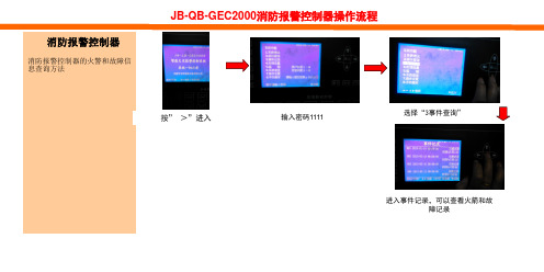
消防报警控制器的火警和故障信 息查询方法
按” >”进入
输入密码1111
选择“3事件查询”
进入事件记录,可以查看火箭和故 障记录
JB-QB-GEC2000消防报警控制器操作流程
消防报警控制器
消防报警控制器的部件信息查询 方法
按” >”进入
按” 4”进入
密码(无)直接按确认键
输入相应的地址号,按确认键
屏蔽灯亮
JB-QB-GST200消防报警控制器操作流程
消防报警控制器
消防报警控制器的取消屏蔽方法
按” 5”进入
输入相应的地址号,按确认键
屏蔽灯灭
按” 0”进入
按“1”火警记录
查看火警信息”
按” 0”进入
按“2”故障记录
查看故障记录
JB-QB-GST200消防报警控制器操作流程
消防报警控制器
消防报警控制器的系统复位的操 作方法
按复位键
密码(无)直接按确
消防报警控制器
消防报警控制器的屏蔽方法
GP 云终端 安装使用手册说明书

GP云终端安装使用手册基康仪器股份有限公司版权声明本文件所含信息归基康仪器股份有限公司所有,文件中所有信息、数据、设计以及所含图样均属基康仪器股份有限公司所有,未经基康仪器股份有限公司书面许可,不得以任何形式(包括影印或其他任何方式)翻印或复制,间接或直接透露给外界个人或团体。
本仪器的安装、维护、操作需由专业技术人员进行,基康仪器股份有限公司对本产品拥有更改的权利,产品更改信息恕不另行通知。
©2022基康仪器股份有限公司版权所有Copyright©2022 China Geokon Instruments Co.,Ltd.目录目录 (3)1. 概述 (4)2. 系统组成 (4)2.1 电源供电 (4)2.2 传感器接入 (4)2.3 设备使用 (7)2.3.1 工作模式及操作说明 (7)2.3.2 设备安装 (8)3. 软件使用说明 (10)附录一:单元及附件配置 (11)附录二:产品外形尺寸图 (13)1.概述GP系列云终端是基于物联网云平台开发的新一代低功耗工程安全监测设备,可接入振弦式、电位计式及数字量等多种类型的传感器;采用极低的功耗设计,休眠模式下功耗小于0.3mW,4G 常在线模式下系统功耗小于50mW;具备GPS定位功能,定位精度≤10米,支持自动校时;内置蓝牙可进行配置、采集;可通过4G/RS485组网,远程控制,通过内置通讯模块和G云平台实现无缝对接,即装即用。
外壳采用全密封壳体封装,自带太阳能板,内置可充电锂电池,防护等级达到IP67,体积小巧、安装方便;适应在各种恶劣环境下全天候工作。
特别适用于有光照的无供电环境。
广泛应用于水电站、水库、公路、桥梁、边坡、地铁、地质灾害等多种环境下的岩土安全自动化监测。
2.系统组成2.1电源供电设备采用可充电锂电池供电,设备内置充电控制电路,标配太阳能板充电,设备外置充电接口可接入5V充电器或5V大功率太阳能板进行快速充电。
七星电子流量计 CS200产品使用手册(E,G) (su)

CS 系列 200-E,G 型
气体质量流量控制器/质量流量计
使用手册
2012.07
目录
第一部分 产品说明
1.1 声明 ................................................... 1 1.2 使用须知 ............................................ 2 1.3 安全注意事项 .................................... 2 1.4 概述 ................................................... 3 1.5 技术指标 ........................................... 4 1.6 标定 ................................................... 5 1.6.1 标准状况 ........................................ 5 1.6.2 制造环境 ........................................ 5 1.6.3 精度调节 ........................................ 5
北京七星华创电子股份有限公司
第 1 页 共 27 页
1.2 使用须知
尊敬的用户,感谢您购买本公司生产的 CS 系列气体质量流量控制器/质量流量计产品。 本手册详细叙述了正确、安全使用该系列产品的必要事项。
产品使用者,请务必认真参阅本手册并理解后使用,在使用过程中,请注意带有 标 志的文字及注意事项中包含的所有内容。
1.4 概述
CS2000系统说明书

CS2000系统说明书目录第一章硬件系统 (3)1.1 系统主要特点 (4)1.2 实验对象组成结构 (4)1.3 控制台组成结构 (7)1.4 RS-485接口转换器与通讯电缆 (11)第二章MCGS组态系统 (13)2.1主控窗口 (13)2.2 设备窗口 (13)2.3 用户窗口 (14)2.4 实时数据库 (14)2.5 运行策略 (14)第一章硬件系统生产与生活的自动化是人类长久以来所梦寐以求的目标,在18世纪自动控制系统在蒸汽机运行中得到成功的应用以后,自动化技术时代开始了。
随着工业技术的更新,特别是半导体技术、微电子技术、计算机技术和网络技术的发展,自动化仪表已经进入了计算机控制装置时代。
在石油、化工、制药、热工、材料和轻工等行业领域中,以温度、流量、物位、压力和成分为主要被控变量的控制系统都称为“过程控制”系统。
过程控制不仅在传统工业改造中,起到了提高质量,节约原材料和能源,减少环境污染等十分重要的作用,而且已成为新建的规模大、结构复杂的工业生产过程中不可缺少的组成部分。
随着计算机控制装置在控制仪表基础上的发展,自动化控制手段也越来越丰富。
其中有在工业领域有着广泛应用的智能数字仪表控制系统、智能仪表加计算机组态软件控制系统、计算机DDC控制系统、PLC控制系统、DCS分布式集散控制系统、FCS现场总线控制系统等。
在现代化工业生产中,过程控制技术正为实现各种最优的技术经济指标、提高经济效益和劳动生产效率、改善劳动条件、保护生态环境等起到越来越大的作用。
CS2000型过程控制实验装置是根据我国工业自动化及相关专业教学特点,吸取了国外同类实验装置的特点和长处,并与目前大型工业装置的自动化现场紧密联系,采用了工业上广泛使用并处于领先的AI智能仪表加组态软件控制系统、DCS(分布式集散控制系统),经过精心设计、多次实验和反复论证后,推出的一套基于本科生、研究生教学和学科基地建设的实验设备。
古老的路由器XG-2000_User Manual(ch)V1.0.14使用手册

4.4.1、Wireless settings..................................................................................................19
4.2.2、DHCP Server.......................................................................................................13
4.2.3、Port Forwarding..................................................................................................15
2.1、产品信息..........................................................................................................................7
2.2、系统安装要求..................................................................................................................7
广州科思通光纤测温系统安装指导手册范本

感温光纤安装指导规市科思通技术二○一二年十二月目录第一章感温光缆介绍. 11. 1 感温光缆简介 1第二章安装准备22. 1 施工组织. 22. 2 施工培训 2第三章感温光缆的安装.隧道空间测温3.1 感温光缆敷设要求 33.2 在电缆桥架上的安装: 53.3 在输煤皮带、煤粉仓等设备上的安装 6 3.4 在变压器上的安装 73.5 在油罐等设备上的安装7第四章系统调试 84.1 注意事项 84.2 温度测试 8第一章感温光纤介绍1. 1 感温光缆简介由科思通研制开发的感温光纤(铠装,耐高温,特制)采用最高等级多模光纤纤芯,根据实际应用场合配置相应光纤紧套包层,并增加不锈钢保护管和抗拉钢丝网等铠装层保护光纤不受损害;外护套为高性能的阻燃材料,具有优良的热传导特性、机械性能、防水性能及抗腐蚀特性。
1:纤芯(Φ62.5mμ)2:涂覆层(Φ125mμ)3:阻燃聚氯乙烯护套(Φ0.9mm)4:聚酰胺纤维5:螺旋金属护套(Φ2.2mm)6:钢丝编织护套(Φ2.5mm)7:阻燃聚氯乙烯护套(Φ2.8mm)第二章安装准备2. 1 施工组织施工前应拟定详细施工计划,选派优秀项目经理主管工程施工,保证人员的配置,确定施工流程,做好人员分工,要责任到人,以保证施工顺利进行。
由于光缆非常脆弱,施工过程中有诸多注意事项,一旦中途更换施工管理人员和施工人员就会造成注意事项的遗忘和前期施工经验的丢失,所以一定要选派固定的、专职的管理人员进行施工组织和统一指挥,若必须更换施工成员,则必须先培训后上岗!2. 2 施工培训施工前需对施工人员进行施工培训和技术交底,施工全过程都要以“安全第一,质量第二,速度第三”为原则,施工过程中应尽量避免更换施工人员,如果有人员变动应及时对其进行培训。
培训至少应包括以下容:进入施工场所要戴安全帽,高空作业要系安全带,不许吸烟光纤易碎易断,不得让其受到锐利的或是表面粗糙的物体的割划,磨擦,碰撞,挤压;不能踩踏,折弯,强拉硬拽光纤光缆接头由瓷制成,安装过程中严禁抛掷、摔打,严禁与金属、地板、墙壁等坚硬物体发生碰撞在拐弯处、穿孔处要特别注意并采取措施保护光缆施工过程中如果有与原设计不符之处或是改动设计之处均应随时记录下来,并最终在系统竣工图上体现施工完毕应将施工现场打扫干净,倒垃圾前要检查是否有工具材料混入其中第三章感温光缆的安装光缆脆弱,极易被折断、踩断,故而我方强烈要求在安装与日后维护的过程中对光缆要特别小心爱护:不能用超过 150 度的物体与其接触或是加热,例如打火机,电烙铁等;不能踩踏,折弯,强拉硬拽光缆。
T2000网管Windows平台安装指导书

目录
目录
1 在 Windows 平台上安装 T2000 ...............................................................................................1-1
文档版本 错误!未知的文档属性名 称 (错误!未知的文档属性名称)
错误!未知的文档属性名称
i
错误!未知的文档属性名称 错误!未知的文档属性名称
插图目录
插图目录
图 1-1 计算机管理 ............................................................................................................................................1-3 图 1-2 新用户 ....................................................................................................................................................1-3 图 1-3 计算机管理 ............................................................................................................................................1-4 图 1-4 t2000 属性 ...............................................................................................................................................1-4 图 1-5 高级选择组 ............................................................................................................................................1-5 图 1-6 安装开始界面 ........................................................................................................................................1-7 图 1-7 准备安装 ................................................................................................................................................1-7 图 1-8 欢迎使用 ................................................................................................................................................1-8 图 1-9 许可证协议 ............................................................................................................................................1-8 图 1-10 客户信息 ..............................................................................................................................................1-9 图 1-11 安装类型...............................................................................................................................................1-9 图 1-12 选择目的地位置.................................................................................................................................1-10 图 1-13 选择时隙 ............................................................................................................................................1-10 图 1-14 开始安装 ............................................................................................................................................1-11 图 1-15 安装状态 ............................................................................................................................................1-11 图 1-16 询问是否安装 SQL Server.................................................................................................................1-12 图 1-17 插入 2 号安装光盘.............................................................................................................................1-12 图 1-18 正在安装 SQL ....................................................................................................................................1-12 图 1-19 正在安装 SQL 补丁 ...........................................................................................................................1-13 图 1-20 “InstallShield Wizard”完成 .................................................................................................................1-13 图 1-21 “cmd.exe DOS”窗口............................................................................................................................1-14 图 1-22 初始化数据库 ....................................................................................................................................1-14 图 1-23 DOS 窗口信息 ....................................................................................................................................1-14 图 1-24 信息 ....................................................................................................................................................1-15 图 1-25 服务管理器 ........................................................................................................................................1-16
RGS 2000 TCAS 回应生成器产品说明书

Y o u r c o m p l e t e R F s o u r c eThe RGS 2000 TCAS Reply Generator is aTest Station designed to beresource for the testing of TCAS (Traffic Alert and Collision Avoidance System) computers. User-friendly menus dis-played on the electroluminescent flat panel allow the operator to:Decode and display Mode S and Mode C Interrogation DataMeasure and display port-to-port relative amplitude and phase of interrogationMeasure and display interrogation pulsecharacteristics including peak pulsepower, pulse frequency, pulse spacing,pulse width, and pulse rise/fall timeMeasure and display interrogation pulsespectrumSimulate up to 154intruders includinggeneration of Mode S and Mode Cinstrument replies, Mode S squitter,Mode C fruit and intruder movementPerform manual or GPIB controlled test-G E N E R A L S P E T R A N S M I T T E R O P E FREQUENCYRange1025 to 1155 MHz Resolution0.1 MHzAccuracy± 0.1 MHz POWERRange-85 to -20 dBm Resolution1.0 dBAccuracy± 1.0 dBPULSE MODULATION Rise Time0.075 ± 0.02 µS Fall Time0.150 ± 0.04 µS Width Mode C0.450 ± 0.05 µS1 Width Mode S0.500 ± 0.05 µS1the very latest specifications visit Resolution0.01 µSAccuracy0.01 µSUUT SPECTRUM ANALYSISScan Center1030 MHzScan Width±90 MHzResolution0.1 MHzAccuracyAmplitude±3 dBFrequency±0.1 MHzInput Power125 W to 500 WDynamic Range>60 dBPOWER REQUIREMENTSVoltage115/230 VAC, 175 WFrequency50/60 HzNote 1: Non-standard reply pulse widths may be specified via the GPIBNote 2: Stated accuracy is valid for most scenarios. The maximum error shall not exceed the displacement of the intruder in 0.1 second as allowed byD0185 par. 2.4.1.2w.P H Y S I C A L C H A R A C T E R I S T I C SWeight109.5 lbs. (49.6 kg)Height12.25" (31.12 kg)Width19" (48.26 kg)Depth20" (50.80 kg)O R D E R I N G I N F O R M A T I O NRGS 2000-06TCAS Reply Generator Collins ITS-700ConfigurationRGS 2000-11TCAS Reply Generator Universal Configuration RGS 2000-16TCAS Reply Generator ATA TELIConfigurationRGS 2000-20TCAS Reply Generator AlliedSignal GAAConfigurationRGS 2000-21TCAS Reply Generator w/o Spectrum Analyzer O P T I O N A L A C C E S S O R I E SACTTA-100A TCAS Interface Unit (used in TPT-81A stations) E X T E N D E D W A R R A N T YWRGS/203C Extended standard warranty 36 months withscheduled calibrationWRGS/205C Extended standard warranty 60 months withscheduled calibrationFor the very latest specifications visit 。
Graco通信网关模块安装配件包说明书
说明书-零配件通信网关模块安装配件包配套用于 HFR ™ 系统,为现场总线提供通信功能。
仅限专业用途。
配件包 24J415ti11985a所示为配备设备网连接器的 CGM3A2583HZH配件包23A2583H目录配件包 . . . . . . . . . . . . . . . . . . . 2相关手册 . . . . . . . . . . . . . . . . . . 2概述 . . . . . . . . . . . . . . . . . . . . 2安装 . . . . . . . . . . . . . . . . . . . . 3设置 . . . . . . . . . . . . . . . . . . . . 5可用内部数据 . . . . . . . . . . . . . . . . 9零配件 . . . . . . . . . . . . . . . . . . .24Graco Standard Warranty . . . . . . . . . . .26Graco Information . . . . . . . . . . . . .26配件包以下配件包为通信网关模块(CGM) 硬件/软件,适用于所有安装。
该配件包配合正确的现场总线设备使用。
下列配件包配合配件包 24J415 使用,包括安装 CGM 所需的其余全部零配件。
有关各个总成的修理零配件,请参见手册 312864。
相关手册概述通信网关模块 (CGM) 提供 HFR 系统与所选现场总线之间的控制链接。
这样便可由外部自动系统进行远程监控。
可由 CGM 获取的传至现场总线的数据,取决于连接至哪个基于 GCA 的系统。
为每个 GCA 系统定义了唯一的数据映射,可使用配件包中提供的令牌获取。
有关现场总线管理员可以查看或修改的 HFR 系统内部数据,请参见可用内部数据列表(第 9 页)。
注: 提供了下列系统网络配置文件•EDS 文件:设备网或以太网/IP 现场总线网络•GSD 文件:PROFIBUS 现场总线网络•GSDML:PROFINET 现场总线网络CGM 零配件号描述24J415CGM 安装配件包(必需)CGM 零配件号现场总线CGMDN0设备网CGMEP0以太网/IP CGMPB0PROFIBUS CGMPN0PROFINET手册描述3A1974CAN 转换接头套件说明312864通信网关模块, 说明书 - 零配件313997HFR 操作313998HRF 修理 - 零配件406897GCA CAN 电缆参考安装3A2583H 3安装1.将 CGM 安装在所需位置。
Comtrol Europe Hostess 2000 硬件安装与配置指南说明书

HOSTESS 2000HARDWARE INSTALLATIONANDCONFIGURATIONGUIDEThis Guide.Comtrol Europe Ltd Document Number. COM281_18Draft Rev B, 24th November 2003Trademark NoticesComtrol, Hostess, Hostess 2000, Universal Interface and RocketPort are trademarks of Comtrol Corporation.Microsoft and Windows are registered trademarks of Microsoft Corporation.Other product names mentioned herein may be trademarks and/or registered trademarks of their respective owners.Copyright © 2003. Comtrol Europe Ltd.All Rights Reserved.Comtrol Europe makes no representations or warranties with regard to the contents of this document or to the suitability of the Comtrol product for any particular purpose. Specifications subject to change without notice. Some software or features may not be available at the time of publication. Contact your reseller for current product information.The Comtrol Europe Ltd Headquarters are atUnit 2, Avonbury Business ParkHowes LaneBicesterOxfordshireOX26 2UAGreat BritainPhone :+44 (0) 1869 323220Fax : +44 (0) 1869 323211Email:******************.ukWeb site : Contents1.0Introduction (1)2.0Caution (2)3.0Installation Overview (4)4.0Set the Base I/O Address Switch Positions (5)5.0Set the Mask Register Switch Positions (10)6.0Set the IRQ Switch Positions (11)7.0Set the UART Clock Speed Links (12)8.0Set the Port Interface Mode Links for Each Port (14)9.0Install the Hostess 2000 in the Host Computer (17)10.0Attach the Comtrol External Interface and Your Peripherals (18)11.0Install the Device Driver (20)Appendix A Technical Support (21)Appendix B Hostess 2000 Specifications (22)1.0 IntroductionThe Hostess 2000The Hostess 2000 products provide traditional Hostess reliability and high data rates in 16550 UART based serial cards. The Hostess 2000 offers a variety of ISA-bus interface models providing RJ11, RJ45, DB9 and DB25 connections supporting 4 to 16 ports. This guide focuses on two versions :Hostess 2000 RJ45 with 4 PortsHostess 2000 16 Port DB25 Multiplexed for connection to a RocketPort Interface2.0 CautionWhen installing Hostess 2000 cards always :• Observe the warnings provided in this guide and those of the host computer and its guide.Important Safety InformationTo avoid contact with electrical current :Warning• Never install electrical wiring during an electrical storm.• Never install the power plug in wet locations.• Always use a screwdriver and other tools with insulated handles.Hostess 2000 Safety InformationThe Hostess 2000 consists entirely of SELV (Low Voltage)circuitry. Ensure a Creepage and Clearance distance of aminimum of 3 mm is maintained between the Hostess 2000 andany Mains (240V AC) or TNV (Telephone circuits). If in doubtask a competent engineer to install the Hostess 2000 in your hostcomputerWhen installing Hostess 2000 cards always :• Observe anti static precautions.CautionTake care when you handle the Hostess 2000, like any electronic device, it is sensitive to static electricity. Use normal static precautions such as wearing an earth ground strap.3.0 Installation OverviewInstallation of a Hostess 2000 follows these general steps : • Set the base I/O address switch positions• Set the Mask Register switch positions• Set the IRQ switch positions• Set the UART clock speed links• Set the port interface mode links for each port• Install the Hostess 2000 in the host computer• Attach the Comtrol external interface and your peripherals • Install the device driver4.0 Set the Base I/O Address Switch PositionsSW2 sets the base I/O addressHostess 2000 4 Port RJ45The physical position of SW2 may vary slightly on different Hostess 2000 products. On the Hostess 2000 16 Port SW2 is positioned nearer the edge of the card.Setting the Base I/O Address Hostess 2000 4RJSW2 Base I/O Address (Address Compare Bits)Switch SW2 the Address Compare Bits switch specifies the I/O address to be used to access the Hostess 2000. The address selected will be the first in a block of 32 that the board will use, for example, setting the base address to 0x0280 will configure the Hostess 2000 to respond to all addresses in the range 0x280 to 0x029FSW2 Setting for : Base Address 240 - Address Range 240 to 25F hexAddress Bits 5 6 7 8 9 10 11 12ON (Value looked for when ON “0”)SW2 Pole 1 2 3 4 5 6 7 8OFF (Value looked for when OFF “1”)SW2 Setting for : Base Address 280 - Address Range 280 to 29F hexAddress Bits 5 6 7 8 9 10 11 12ON (Value looked for when ON “0”)DEFAULTSW2 Pole 1 2 3 4 5 6 7 8OFF (Value looked for when OFF “1”)The factory default setting of I/O address 0x280 is configured by selecting SW2 switch positions :Poles 1, 2, 4, 6, 7 and 8 “ON” Value 0Poles 3 and 5 “OFF” Value 1Note : The default I/O address from the factory is set to 280500SW2 Setting for : Base Address 500 - Address Range 500 to 51F hexAddress Bits 5 6 7 8 9 10 11 12ON (Value looked for when ON “0”)SW2 Pole 1 2 3 4 5 6 7 8OFF (Value looked for when OFF “1”)SW2 Setting for : Base Address 580 - Address Range 580 to 59F hexAddress Bits 5 6 7 8 9 10 11 12ON (Value looked for when ON “0”)SW2 Pole 1 2 3 4 5 6 7 8OFF (Value looked for when OFF “1”)Note :SW2 Pole 8 must be “ON” for a 4 Port Hostess 2000 and “OFF” for an 8 Port Hostess 2000. The 8 Port default is 3, 5 and 8 “ON” giving 280 to 2BFHostess 2000 4RJ Understanding how the Binary 8 pole switch represents the Hex values5 6 7 8 9 10 11 12ON (Value looked for when ON “0”) SW21 2 3 4 5 6 7 8OFF (Value looked for when OFF “1”)Address Bit 0 1 2 3 4 5 6 7 8 9 10 11 12 13 14 150 1 2 3 4 5 6 7 8 9 A B C D E F Hex 1 2 4 8 1 2 4 8 1 2 4 8 1 2 4 8 Binary 0 0 0 0 0 0 0 1 0 1 0 0 0 0 0 0 I/O Base Address 0 8 2 0Note : Read the I/O Base address from right to leftSetting the Base I/O Address Hostess 2000 16 DB25SW2 Base I/O Address (Address Compare Bits)Switch SW2 the Address Compare Bits switch specifies the I/O address to be used to access the Hostess 2000 16 DB25. The card requires 0x80 (128 Decimal) locations in I/O space. The default I/O address is 0x500SW2 Setting for : Base Address 280 - Address Range 500 to 57F hexAddress Bits 7 8 9 10 11 12 13 14ON (Value looked for when ON “0”)DEFAULTSW2 Pole 1 2 3 4 5 6 7 8OFF (Value looked for when OFF “1”)The factory default setting of I/O address 0x500 is configured by selecting SW2 switch positions :Poles 1, 3, 5, 6, 7 and 8 “ON” Value 0Poles 2 and 4 “OFF” Value 1SW2 Setting for : Base Address 240 - Address Range 200 to 27F hex Address Bits 7 8 9 10 11 12 13 14 ON (Value looked for when ON “0”)SW2 Pole 1 2 3 4 5 6 7 8 OFF (Value looked for when OFF “1”)SW2 Setting for : Base Address 500 - Address Range 280 to 2FF hex Address Bits 7 8 9 10 11 12 13 14 ON (Value looked for when ON “0”)SW2 Pole 1 2 3 4 5 6 7 8 OFF (Value looked for when OFF “1”)SW2 Setting for : Base Address 580 - Address Range 580 to 5FF hex Address Bits 7 8 9 10 11 12 13 14 ON (Value looked for when ON “0”)SW2 Pole 1 2 3 4 5 6 7 8 OFF (Value looked for when OFF “1”)Hostess 2000 16 DB25 Understanding how the Binary 8 pole switch represents the Hex values5 6 7 8 910 11 12ON (Value looked for when ON “0”) 1 2 3 4 5 6 7 8 SW2OFF (Value looked for when OFF “1”) Address Bit 0 1 2 3 4 5 6 7 8 9 10 11 12 13 14 15 0 1 2 3 4 5 6 7 8 9 A B C D E F Hex 1 2 4 8 1 2 4 8 1 2 4 8 1 2 4 8 Binary0 00 0 0 1 0 1 0 0 0 0I/O Base Address 0 0 5 0Note : Read the I/O Base address from right to left5.0 Set the Mask Register Switch PositionsSetting SW1 Pole 1 “Mask Register” (All Hostess 2000 card types)Hostess 2000 4 Port RJ45 The mask register function is available through Switch SW1Pole 1 of the SW1 is the “Mask Register” enable signal. This signal, when enabled by selecting Pole 1 to be “ON”, allows the driver to enable or disable the interrupt for each serial port present; when set to “OFF” all interrupts are enabled and the “Mask Register” has no effect.For Comtrol supplied drivers, the Microsoft operating systems expect this to be “OFF” (e.g. DOS, Windows 95, 98, NT, also QNX, OS/2)The Unix like operating systems expect it to be “ON” (e.g. AT&T, Interactive 386/ix, Microport V/386, SCO Xenix, SCO Unix, SCO OpenServer, SunOS).SW1 Setting for : Pole 1 “Mask Register” ONSW1 Pole 1 2 3 4 5 6 7 8 OFFM A S K6.0 Set the IRQ Switch PositionsSetting the IRQ Switch Positions (All Hostess 2000 card types)Hostess 2000 4 Port RJ45SW1 Poles 2 to 8 select which physical IRQ line to be used. No more than one of these is to be “ON” at any given time.The default IRQ setting is IRQ5. This board cannot share its IRQ with any other board.SW1 Setting for : IRQ ONSW1 Pole 1 2 345678OFFM A S KI R Q 2 o r 9 I R Q 3I R Q 4I R Q 5I R Q 7I R Q 10I R Q 117.0 Set the UART Clock Speed LinksSetting Jumpers J3 and J4 UART Clock Speed (All Hostess 2000 card types)Hostess 2000 4 Port RJ45There are four UART clock speed settings available, they are selected using the pin headers J3 and J4. All the Comtrol standard drivers use the slowest clock speed (unless otherwise stated), this is therefore the default setting. It is possible to use faster clock speeds in which case the actual baud rates selected will be faster in proportion to the speed increase. Some of the other settings exist to allow users to write their own software to have special baud rates generated exactly.The table below lists the speeds available and the multiplication ratio showing how much faster the real baud rate will be relative to the driver assuming a 1.8432 MHz clock.Jumpers J3 and J4 UART Clock SpeedJumper J3 Jumper J4 Clock rate Multiplication factor Link Not Fitted Not Fitted 1.8432 MHz x 1 DEFAULTLink Not Fitted Link Fitted 8.192 MHz x 4.444444Link Fitted Link Not Fitted 14.7456 MHz x 8Link Fitted Link Fitted 16 MHz x 8.680555Figure 1 below shows the default setting with no links fitted to J3 and J4Figure 1When selecting baud rates and UART clock speeds, remember that the maximum speed that the RS-232 parts are rated for is 230.4 kbaud, and the RS-422/485 parts are rated up to 250 kbaud. If baud rates faster than this are required contact Comtrol.J3 J48.0 Set the Port Interface Mode Links for Each Port Communication Mode SelectionHostess 2000 4 Port RJ45Each port is independently configured for its operating mode using a 5 x 2 Jumper block. This block is associated with each port according to the table below:Port Number Jumper Block0 J71 J82 J93 J10To use the Jumper blocks it will be noticed that there are numbers (1 to 5) for each position to fit a link. The table below shows how each mode may be selected with reference to fitting links in these numbered positions. This list is not exhaustive and other combinations than those shown below are not to be used.ON – Link fittedOFF – Link not fittedLink 5 Link 4 Link 3 Link 2 Link 1 Mode Notes OFF ON ON OFF OFF RS-232OFF ON ON ON ON RS-422(normal) Transmitter and receiver always enabledOFF OFF ON OFF ON RS-422(hot standby) Transmitter and receiver enabled by RTS OnOFF ON OFF ON OFF RS-422(hot standby) Transmitter and receiver enabled by DTR OnON OFF ON OFF ON RS-485(normal) Transmit when RTS On Receive when RTS OffON ON OFF ON OFF RS-485(normal) Transmit when DTR On Receive when DTR OffON OFF ON ON OFF RS-485(hot standby) Transmit when DTR On Receive when RTS OnON ON OFF OFF ON RS-485(hot standby) Transmit when RTS On Receive when DTR OnON ON ON OFF ON RS-485 (receiveralways on) Transmit when RTS On Receive alwaysON ON ON ON OFF RS-485 (receiveralways on) Transmit when DTR On Receive alwaysOFF ON ON ON ON RS-485 (four-wire master) Transmit always Receive alwaysOFF ON ON OFF ON RS-485 (four-wire slave) Transmit when RTS On Receive alwaysOFF ON ON ON OFF RS-485 (four-wire slave) Transmit when RTS On Receive alwaysOFF OFF OFF OFF OFF Port DisabledNote: The standard drivers may not have all the modes above available, in most cases only RS-232 and RS-422 (normal) are supported.Hostess 2000 RJ8When configuring the RJ8 and additional 4 sets of headers will need to be configured. Hostess 2000 8 or 16 DB25When configuring the 16 DB25 it has no on board port interface mode headers. It connects directly to a Rocket Port Interface which has its own configuration guide. Use a RocketPort Interface for RS232 or RS422Use a Universal interface for RS485 or special versions of RS232.Figure 2 below shows Port 0 configured for RS-232PORT 0 MODE54321J7Figure 29.0 Install the Hostess 2000 in the Host ComputerCheck the switches and links are configured for your chosen installation as described earlier in this guide.Always follow Safety and static precaution guidelines.If in doubt ask a competent engineer to install the Hostess 2000 in your host computer Using the Host Computer instructions :1. Shut down the host System2. Turn the power switch for the host system supply to the OFF position3. Disconnect the mains plug from the power socket4. Remove the host system cover5. Select a slot to install the Hostess 20006. Remove the expansion slot cover7. Insert the Hostess 2000 in the expansion slot, making sure that it is properlyseated8. Attach the Hostess 2000 to the chassis with the expansion slot screw9. Repeat steps 5 to 8 for each Hostess 200010. Replace the cover on the host system10.0 Attach the Comtrol External Interface and YourPeripheralsConnector PinoutsThis board will have been built in either of two styles, one uses RJ-45 connectors and the other uses a DB37 and “Quadcable” attachment to provide four DB25 plug connections. Note : It is important to note that the documentation for the predecessor to this board, specifically the Hostess 554, showed the RS-422 signal polarity incorrectly. This document shows the pin connections as they really are. The consequence of this is that it makes the pinout of this board look inconsistent with respect to the older product but this is not the case and the two boards can be interchanged without affecting the cable arrangements previously made. The naming convention for these signals uses “+” and “A” interchangeably, and likewise “-.” is synonymous with “B”.RJ-45 connectors have 8 pins, the function of these depends on whether RS-232 or RS-422/485 is selected. Also in RS-422/485 mode. This is detailed in the tables below:RJ-45 in RS-232 ModePin Number Signal Direction with respect to this card1 RTS Output2 DTR Output3 Ground -4 TXD Output5 RXD Input6 DCD Input7 DSR Input8 CTS InputRJ-45 in RS-422 ModePin Number Signal Direction with respect to this card1 TXD- Output2 - -3 Ground -4 RXD- Input5 RXD+ Input6 - -7 - -8 TXD+ OutputRJ-45 in RS-485 ModePin Number Signal Direction with respect to this card1 TXD-/RXD- Output/Input2 - -3 Ground -4 - -5 - -6 - -7 - -8 TXD+/RXD+ Output/InputIn either RS-422 or RS-485 mode, the “Ground” signal is not necessary, however, as it remains connected at the socket the user is made aware to avoid accidentally connecting to this pin.“Quadcable” boards have a DB37 Socket instead of the RJ-45 connector and is supplied with a cable assembly that converts from one DB37 Socket to four DB25 Plugs. The pinouts of these DB25 connectors depends on whether RS-232 or RS-422/485 has been selected. The pinout for the DB25 plugs is shown below:DB25 Plug in RS-232 ModePin Number Signal Direction with respect to this card2 TXD Output3 RXD Input4 RTS Output5 CTS Input6 DSR Input7 Ground -8 DCD Input20 DTR Output22 RI InputDB25 Plug in RS-422 ModePin Number Signal Direction with respect to this card2 RXD- Input3 RXD+ Input4 TXD- Output5 TXD+ Output7 Ground -DB25 Plug in RS-485 ModePin Number Signal Direction with respect to this card4 TXD-/RXD- Output/Input5 TXD+/RXD+ Output/Input7 Ground -When RS-422 mode is selected the RS-232 signals DTR, DSR and DCD are active and may be used if required. Their connector positions are the same as in RS-232 mode.11.0 Install the Device DriverCurrent drivers are available from the Comtrol US office website. \download.aspFollow the installation instructions provided with the device driversAppendix A Technical SupportIf you need technical support, contact Comtrol Europe using one of the following methods.Comtrol EuropeContactMethodEmail ******************.ukWeb site Fax +44 (0) 1 869-323-211Phone +44 (0) 1 869-323-220Appendix B Hostess 2000 SpecificationsHardware SpecificationsThe following table lists hardware specifications for the Serial Hub Solo.Topic Specification Supply inputHostess 2000 4J Hostess 2000 8J Hostess 2000 8 DB25 Hostess 2000 16 DB25 +5VDC rated at 190 mA +12VDC rated at 20 mA -12VDC rated at 20 mA +5VDC rated at 250 mA +12VDC rated at 80 mA -12VDC rated at 80 mA +5VDC rated at 215 mA +12VDC N/A-12VDC N/A+5VDC rated at 300 mA +12VDC N/A-12VDC N/APower consumption :Hostess 2000 4J Hostess 2000 8J Hostess 2000 8 DB25 Hostess 2000 16 DB25 2.38 Watts3.17 Watts 1.08 Watts 1.50 WattsUART type 16C554 or equivalent Baud rate/port (maximum)Using 1.8432 MHz clock Or when using a faster clock 50 baud to 115.2 kbaudUp to 230.4 kbaud (RS232) Up to 250 kbaud (RS-422/485)Serial interface RS-232, RS-422, and RS-485 Connector types :Hostess 2000 4J Hostess 2000 8J Hostess 2000 8 DB25 Hostess 2000 16 DB25 4 RJ45 8 way connectors8 RJ45 8 way connectorsDB25 25 way D type (Multiplexed) DB25 25 way D type (Multiplexed)Data bits Parity Stop bits 5, 6, 7 or 8Odd, Even, None, Mark or Space 1, 1.5 or 2Modem control signals RS-232 : RTS, CTS, DTR, DSR & DCD(RI is available on DB25 versions).RS-422 : None, RTS and DTR may beused for transceiver enable control Bus interface ISAI/O address space requirements Any 32 byte block aligned to a 32 byteboundary in the range 0x0000 to 0x1FE0 Memory address space requirements NoneISA bus interrupt One from IRQ2, IRQ3, IRQ4, IRQ5,IRQ7, IRQ10 or IRQ11,Supported operating systems DOS, OS/2, Linux, Win 3.1, Win NT, Win9X, Unix, Xenix, SCO, Multiuser DOS.Dimensions (Excluding cables) : Hostess 2000 4JHostess 2000 8JHostess 2000 8 DB25 Hostess 2000 16 DB25 H x W x D approximate22 mm x 170 mm x 120 mm 22 mm x 170 mm x 120 mm 22 mm x 170 mm x 120 mm 22 mm x 170 mm x 120 mmWeight (Excluding cables) :Hostess 2000 4J Hostess 2000 8J Hostess 2000 8 DB25 Hostess 2000 16 DB25 90 g 104 g 95 g 106 gEnvironmental SpecificationsThis table lists the environmental conditions.Environmental Conditions Value Air temperature :System on (operational) System off (storage) 0 to 50°C -20 to 85°CAltitude 0 to 10,000 feet Heat output :Hostess 2000 4J Hostess 2000 8J Hostess 2000 8 DB25 Hostess 2000 16 DB25 2.38 Watts3.17 Watts 1.08 Watts 1.50 WattsHumidity (non-condensing) :System on (operational) System off (storage) 5% to 90% 5% to 95%Mean time between failures (MTBF) : (Excluding external interface)Hostess 2000 4J Hostess 2000 8J Hostess 2000 8 DB25 Hostess 2000 16 DB25Greater than 30 years estimated Greater than 30 years estimated Greater than 30 years estimated Greater than 30 years estimatedNoticesRadio Frequency Interference (RFI)This equipment generates, uses, and can radiate radio frequency energy, and if not installed and used in accordance with the instruction manual, may cause harmful interference to radio communications. However, there is no guarantee that interference will not occur in a pa rticular installation. If this equipment does cause harmful interference to radio or television reception, which can be determined by turning the equipment off and on, the user is encouraged to try and correct the interference by one or more of the following measures :• Reorient or relocate the receiving antenna.• Increase the separation between the equipment and the receiver.• Connect the equipment into an outlet on a circuit different from that to which the receiver is connected.• Consult the dealer or an experienced radio/TV technician for help.。
Sun StorEdge Enterprise 2 Gb FC 单端口和双端口主机总线适配器安装指南

Sun StorEdge Enterprise™ 2 Gb FC单端口和双端口主机总线适配器安装指南Sun Microsystems, Inc.文件号码 819-3781-112006 年 3 月,修订版 A请将有关本文档的意见和建议提交至:/hwdocs/feedback请回收版权所有 2006 Sun Microsystems, Inc., 4150 Network Circle, Santa Clara, California 95054, U.S.A. 保留所有权利。
对于本文档中介绍的产品,Sun Microsystems, Inc. 对其所涉及的技术拥有相关的知识产权。
需特别指出的是(但不局限于此),这些知识产权可能包含在 /patents 中列出的一项或多项美国专利,以及在美国和其他国家/地区申请的一项或多项其他专利或待批专利。
本文档及其相关产品的使用、复制、分发和反编译均受许可证限制。
未经 Sun 及其许可方(如果有)的事先书面许可,不得以任何形式、任何手段复制本产品或文档的任何部分。
第三方软件,包括字体技术,均已从 Sun 供应商处获得版权和使用许可。
本产品的某些部分可能是从 Berkeley BSD 系统衍生出来的,并获得了加利福尼亚大学的许可。
UNIX 是 X/Open Company, Ltd. 在美国和其他国家/地区独家许可的注册商标。
Sun 、Sun Microsystems 、Sun 徽标、AnswerBook2、 、Sun StorEdge 、Sun Fire 、SunSolve Online 、SunVTS 和 Solaris 是 Sun Microsystems, Inc. 在美国和其他国家/地区的商标或注册商标。
所有 SPARC 商标的使用均已获得许可,它们是 SPARC International Inc. 在美国和其他国家/地区的商标或注册商标。
标有 SPARC 商标的产品均基于由 Sun Microsystems, Inc. 开发的体系结构。
GEC2000安装使用说明书

2.1 系统组成 ...................................................................................................................................5 2.2 GEC2000 控制器模块结构说明 ..............................................................................................6 2.2.1 显示模块 ...........................................................................................................................6 2.2.2 回路模块 ...........................................................................................................................7 2.2.3 直接联动模块 ...................................................................................................................8 2.2.4 电源模块 ...........................................................................................................................8 第3章 3.1 3.2 3.3 3.4 安装与调试 .........................................................................................................................10 开箱检查 .................................................................................................................................10 控制器的安装条件 .................................................................................................................10 开机检查 .................................................................................................................................10 工程安装、调试 .....................................................................................................................10
火星舱安装说明

火星舱初次安装手册天津火星科技有限公司2011年9月20日第1章硬件设备 (1)1.1准备DOM (1)1.2调火星舱BIOS (1)第2章网络配置.............................................................................. 错误!未定义书签。
2.1设置和修改火星舱主机名 .................................................. 错误!未定义书签。
2.2配置和修改火星舱网络配置 .............................................. 错误!未定义书签。
第3章用户登录. (3)3.1登录 (3)3.2创建系统卷SYSVOL (5)3.3注册管理 (6)3.4火星舱服务器名主节点菜单 (7)第4章更换DOM盘 (9)第1章硬件设备1.1准备DOM准备DOM盘插入火星舱(例如因为火星舱设备已经拉走,所以暂用PC机上插入火星舱为例),插入的槽的编号必须是“0”,火星舱具体设备可参见硬件说明书。
1.2调火星舱BIOS火星舱的BIOS与PC机不同,调BIOS按屏幕提示即可,此处以PC机为例,将PC机的BIOS设置成SATADOM盘为第一启动项,如图:F10保存退出后,重新启动PC机。
登录火星舱系统,选择第一启动项,回车;如图天津火星科技有限公司第1页共12页第2章用户登录2.1登录登录火星舱的web界面,需要在登录的操作系统安装JRE(Java Runtime Environment),主要是支撑火星舱的Java启动界面,注意,此版本要求在JRE1.6以上版本。
安装完JRE1.6后方可进行软件的登录。
通过浏览器输入火星舱服务器IP地址进入火星舱软件控制台,在进入前显示启动界面。
如图所示,在地址栏中输入IP地址192.168.100.1回车后,会自动下载一个文件名为MSAClient.jnlp的文件,下载完成后打开它,会弹出“用户登录”界面。
在界面中通过拖动鼠标来调整旋转角度-宏山激光

用户手册
退出
目录
机器安装操作 机器面板操作 机器软件安装 机器软件操作
安装激光管 安装激光管共分四步: 1.打开两个圆形支座的上半圆,将激光管出光口(负极端)朝一号反射镜方向 小心地放在圆形支座上,如图:
正 极 端 ( 高 压 端 )
圆 形 支 座
负 极 端 ( 出 光 口 )
水管接口
水箱的安装
将水箱注满纯净水,水箱的进水口接到激光机的出水口,水箱的出水口 接到激光机的进水口,水箱的信号线接激光机信号线,如图:
激光机进水口 水箱进水口 水箱出水口 水箱航空接头 激光机航空接头
激光机出水口
安装气泵
气泵的出风口 接 激光机的进风口
气泵的出风口
激光机的进风口
气泵的作用 气泵将周围的空气抽过来,空气通过管道,最后从激光头的出光口吹出,共三个作用: 1. 冷却下面的切割材料; 2. 冷却镜筒里面的聚焦镜; 3. 防止烟通过激光头的出光口进入镜筒,熏坏聚焦镜;
第2光路
工作台面
外
里
第3光路
光路的调试 我们的切割机在使用中,有可能会发生光路偏移,导致无光或光路不正现 象,这时请参照以下方法将光路调整正确: 第一步:先保证从激光管发出的光束入射在1#反光镜的中心。
打在圆 圈中心
第二步:在2#反光镜前贴上美纹纸(或其它能打出标记的物体),将横梁 移至最靠近激光管的位置,按点射(控制适当的光强),打上一个标记1(注 意:为防止激光辐射伤人,请先用一块纸板测试出光斑的大概位置,然后再 进行调整)。 第三步:逐渐将横梁移至离激光管最远的位置,按点射,打上一个标记2。
2#反光镜调节螺丝示意图
3#反光镜位置
- 1、下载文档前请自行甄别文档内容的完整性,平台不提供额外的编辑、内容补充、找答案等附加服务。
- 2、"仅部分预览"的文档,不可在线预览部分如存在完整性等问题,可反馈申请退款(可完整预览的文档不适用该条件!)。
- 3、如文档侵犯您的权益,请联系客服反馈,我们会尽快为您处理(人工客服工作时间:9:00-18:30)。
GEC2000-SC安装说明
(GEC2000-SC因为是以卡环形式安装,所以以下都以卡环简称)
1、首先记录好卡环的编号以及所对应的触头相性。
2、把电木螺丝松开至卡环能自由开合。
3、揭去导热硅胶表面覆盖的薄膜再把卡环稍微分开推进静触头盒内扣住静触头,试着合上
卡环看是否能完全合上,如果不能合上的话,先把卡环从静触头上拿出了,根据刚才的情况判断需要调整内径的大小(以撕掉卡环内的导热硅胶片的多少来达到调整的目的,注:尽量不要撕靠电路板侧的导热硅胶片,特别是用手触摸能感觉到有一个明显突出点部位附近的硅胶片不能撕掉,该突出点是温度感应元件,导热硅胶片的作用是是给温度感应元件传输温度和防滑)
4、经过调整导热硅胶片后再把卡环推进静触头盒内扣住静触头,用手指压紧卡环两侧,感
觉到能把卡环完全合上并且有一定的弹力时表明卡环内径大小合适。
5、调整卡环位置,让卡环的元器件所在位置的半环在静触头的下面,并确保卡环已经推到
触头底部,夹紧卡环两侧用大号一字螺丝刀(一字口宽度越宽越好)轻轻拧紧电木螺丝(注意:拧紧电木螺丝时不能蛮力,如果感觉到不能拧动了马上停止以防拧断电木螺丝。
)拧紧后用手轻轻晃动卡环看是否松动,如果松动的话再夹紧卡环两侧拧紧电木螺丝。
6、如果在安装的时候因为触头盒空间太小不能用手夹紧卡环的话可以用两个大号螺丝刀
(连把手长度约为25CM)分别夹在卡环上下侧以杠杆原理压紧卡环以达到闭合的目的,卡环合上后再用另一个手用大号一字螺丝刀拧紧电木螺丝。
