C0402C56312RAC中文资料
proteus元件对照表经典详细

proteus元件对照表经典详细在电子电路设计与仿真领域,Proteus 软件是一款非常实用的工具。
对于初学者或者经验丰富的工程师来说,了解 Proteus 中的元件及其对应的功能和特性是至关重要的。
本文将为您提供一份详尽且经典的Proteus 元件对照表,帮助您更好地理解和运用这款软件。
一、电阻类元件1、固定电阻(Resistor)常见的封装形式有 0805、0603 等。
电阻值可以通过设置进行调整,单位为欧姆(Ω)。
2、可变电阻(Variable Resistor)也称为电位器(Potentiometer)。
可以通过滑动端改变电阻值,常用于调节电路中的电压或电流。
3、排阻(Resistor Array)多个电阻集成在一个封装内,常见的有 4 引脚和 8 引脚的排阻。
二、电容类元件1、电解电容(Electrolytic Capacitor)有极性,正负极不能接反。
容量通常较大,常用于电源滤波等电路。
2、陶瓷电容(Ceramic Capacitor)无极性。
容量相对较小,稳定性较好。
3、钽电容(Tantalum Capacitor)性能优于电解电容,但价格相对较高。
三、电感类元件1、空心电感(Air Core Inductor)电感量相对较小。
2、铁芯电感(Iron Core Inductor)具有较高的电感量。
3、贴片电感(Chip Inductor)适用于表面贴装技术。
四、二极管类元件1、普通二极管(Diode)具有单向导电性。
2、发光二极管(Light Emitting Diode,LED)通电时会发光,颜色多样。
3、稳压二极管(Zener Diode)能在一定电压范围内保持稳定的电压。
五、三极管类元件1、 NPN 型三极管(NPN Transistor)由三块半导体组成,具有电流放大作用。
2、 PNP 型三极管(PNP Transistor)与 NPN 型三极管工作原理相似,但极性相反。
焊机常用电源芯片
焊机常用电源芯片(中英文实用版)英文文档:Title: Common Power Supply Chips for Welding MachinesWelding machines are essential tools in various industries, and their performance is highly dependent on the quality and type of power supply chips used.Power supply chips play a crucial role in regulating and stabilizing the power output of welding machines, ensuring consistent and reliable welding operations.One commonly used power supply chip in welding machines is the integrated circuit (IC) controller.This chip is responsible for managing the flow of electricity and maintaining the desired output voltage and current levels.It protects the machine from overcurrent, overvoltage, and short-circuit conditions, ensuring safe and reliable operation.Another essential type of power supply chip used in welding machines is the voltage regulator.This chip ensures that the voltage supplied to the welding torch and other components remains stable, regardless of fluctuations in the input voltage.Voltage regulators are available in different types, such as linear regulators and switching regulators, each offering specific advantages in terms of efficiency and size.Furthermore, power supply chips for welding machines often includeprotection features, such as overtemperature protection and undervoltage lockout.These features help prevent damage to the welding machine due to excessive heat or low voltage conditions, extending the lifespan of the equipment.In conclusion, the choice of power supply chips for welding machines is crucial for achieving optimal performance, reliability, and safety.By selecting the appropriate power supply chips, welders can ensure efficient and consistent welding operations, even in challenging environments.中文文档:标题:焊接机常用电源芯片焊接机是各种行业中不可或缺的工具,其性能在很大程度上取决于所使用电源芯片的质量和类型。
cm2塑料外壳式断路器
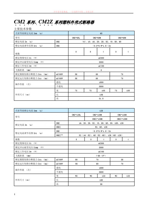
C M 2...系列、...C M 2Z ....系列塑料外壳式断路器.......... 壳架等级额定电流Inm (A ) 63型号CM2-63LCM2-63MCM2-63H额定电流In (A )CM2 (6)、10、16、20、25、32、40、50、63整定电流调节范围Ir1 (A ) CM2(0.8-0.9-1.0)In 极数3 34 34额定绝缘电压Ui (V ) AC800 额定冲击耐受电压Uimp (V ) 8000 额定工作电压Ue (V ) AC400 飞弧距离 (mm )额定极限短路分断能力Icu (kA ) AC400V 35 50 70 额定运行短路分断能力Ics (kA ) AC400V 3550 70 操作性能 (次)通电 1500 不通电 8500 外形尺寸(㎜)宽7878103 78103长 135 高81.5壳架等级额定电流Inm (A ) 125 型号CM2-125LCM2-125M CM2-125HCM2Z-125MCM2Z-125H额定电流In (A )CM2 16、20、25、32、40、50、63、80、100、125CM2Z 32、63、125 整定电流调节范围Ir1 (A ) CM2 (0.8-0.9-1.0)InCM2Z **32(16~32)、63(32~63)、125(63~125)极数3 34 34额定绝缘电压Ui (V ) AC800 额定冲击耐受电压Uimp (V ) 8000 额定工作电压Ue (V ) AC400 飞弧距离 (mm )≯50(0*)额定极限短路分断能力Icu (kA ) AC400V 50 70 85 额定运行短路分断能力Ics (kA ) AC400V 3550 70操作性能 (次)通电 1500 不通电 8500外形尺寸(㎜) 宽92 92 122 92 122长 150 高85**注:CM2Z整定电流连续可调。
CM602无件代码与进料方向
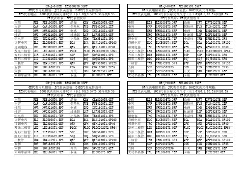
OR-J-0402R RES1005T0.35PF 0R代表电阻阻值,J代表误差值,0402代表元件规格, RES代表电阻, 1005代表实际元件尺寸(长1.0宽0.5)T0.35厚度0.35 PF代表纸带,EF代表塑胶带 电阻 RES RES1005T0.3PF 晶振 CRY CRY8020T5.0EF 电容 CAP CAP1005T0.5PF 保险丝 FUS FUS4020T1.2EF 排阻 NWR NWR3216T0.5PF 电感 IND IND1608T1.0EF 排容 NWC NWC3216T0.8PF 过滤器 LCF LCF3525T3.0EF 钽电容 TNC TNC3216T1.7EF 小晶体 TRM TRM3512T1.3P3 点解电容 ELC ELC5050T4.5EF BGA BGA BGA1010T1.0P100 可调电容 TRC TRC3020T2.0EF QFN QFN QFN1010T1.0P40 发光二极管 LED LED1608T1.0EF PLCC PLCC PLCC2020T2.5P64 方形二极管 DIR DIR3216T1.2EF SOP SOP SOP5040T1.2P8 圆形二极管 DIC DIC3216T2.0EF SOJ SOJ SOJ5050T1.5P8 三极管 TRM TRM1429T1.3P3 QFP QFP QFP3030T1.5P120 五脚 SOP SOP1630T1P5 CON CON COM1020T1.2P35 六脚 SOP SOP1630T1P6 开关 SWH SWH2125T1.6EF 大功率晶体 TRL TRL1060T1.7EF 卡座 KZ KZ2828T2.0EF OR-J-0402R RES1005T0.35PF 0R代表电阻阻值,J代表误差值,0402代表元件规格, RES代表电阻, 1005代表实际元件尺寸(长1.0宽0.5)T0.35厚度0.35 PF代表纸带,EF代表塑胶带 电阻 RES RES1005T0.3PF 晶振 CRY CRY8020T5.0EF 电容 CAP CAP1005T0.5PF 保险丝 FUS FUS4020T1.2EF 排阻 NWR NWR3216T0.5PF 电感 IND IND1608T1.0EF 排容 NWC NWC3216T0.8PF 过滤器 LCF LCF3525T3.0EF 钽电容 TNC TNC3216T1.7EF 小晶体 TRM TRM3512T1.3P3 点解电容 ELC ELC5050T4.5EF BGA BGA BGA1010T1.0P100 可调电容 TRC TRC3020T2.0EF QFN QFN QFN1010T1.0P40 发光二极管 LED LED1608T1.0EF PLCC PLCC PLCC2020T2.5P64 方形二极管 DIR DIR3216T1.2EF SOP SOP SOP5040T1.2P8 圆形二极管 DIC DIC3216T2.0EF SOJ SOJ SOJ5050T1.5P8 三极管 TRM TRM1429T1.3P3 QFP QFP QFP3030T1.5P120 五脚 SOP SOP1630T1P5 CON CON COM1020T1.2P35 六脚 SOP SOP1630T1P6 开关 SWH SWH2125T1.6EF 大功率晶体 TRL TRL1060T1.7EF 卡座 KZ KZ2828T2.0EF
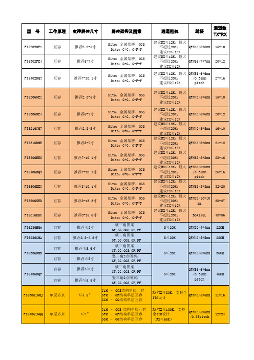
敦泰触摸IC参数对照表
20*12
FT5402DQT
互容
推荐7-10.1寸
27*16
FT5206GE1
互容
推荐2.8-5寸
Sito:金属架桥,OGS Dito:G+G,G+F+F Sito:金属架桥,OGS Dito:G+G,G+F+F Sito:金属架桥,OGS Dito:G+G,G+F+F Sito:金属架桥,OGS Dito:G+G,G+F+F Sito:金属架桥,OGS Dito:G+G,G+F+F Sito:金属架桥,OGS Dito:G+G,G+F+F Sito:金属架桥,OGS Dito:G+G,G+F+F Sito:金属架桥,OGS Dito:G+G,G+F+F Sito:金属架桥,OGS Dito:G+G,G+F+F 横三角图案: GF,GG,OGS,GP,PF 横三角图案: GF,GG,OGS,GP,PF 横三角图案: GF,GG,OGS,GP,PF 竖三角2点图案: GF,GG,OGS,GP,PF 横三角图案: GF,GG,OGS,GP,PF 竖三角2点图案: GF,GG,OGS,GP,PF G1M – OGS结构单层互容 GFM – GF结构单层互容 GGM – GG结构单层互容 G1M – OGS 结构单层互容 GFM – GF结构单层互容 GGM – GG结构单层互容
工作电流:6mA 待机电流:4mA 睡眠电流:30uA
工作温度: -20~+85 储存温度: -55~+150 工作温度: -20~+85 储存温度: -55~+150
(完整word版)IC集成电路型号大全及40系列芯片功能大全,推荐文档
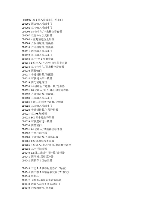
CD4000 双3输入端或非门单非门CD4001 四2输入端或非门CD4002 双4输入端或非门CD4006 18位串入/串出移位寄存器CD4007 双互补对加反相器CD4008 4位超前进位全加器CD4009 六反相缓冲/变换器CD4010 六同相缓冲/变换器CD4011 四2输入端与非门CD4012 双4输入端与非门CD4013 双主-从D型触发器CD4014 8位串入/并入-串出移位寄存器CD4015 双4位串入/并出移位寄存器CD4016 四传输门CD4017 十进制计数/分配器CD4018 可预制1/N计数器CD4019 四与或选择器CD4020 14级串行二进制计数/分频器CD4021 08位串入/并入-串出移位寄存器CD4022 八进制计数/分配器CD4023 三3输入端与非门CD4024 7级二进制串行计数/分频器CD4025 三3输入端或非门CD4026 十进制计数/7段译码器CD4027 双J-K触发器CD4028 BCD码十进制译码器CD4029 可预置可逆计数器CD4030 四异或门CD4031 64位串入/串出移位存储器CD4032 三串行加法器CD4033 十进制计数/7段译码器CD4034 8位通用总线寄存器CD4035 4位并入/串入-并出/串出移位寄存CD4038 三串行加法器CD4040 12级二进制串行计数/分频器CD4041 四同相/反相缓冲器CD4042 四锁存D型触发器CD4043 三态R-S锁存触发器("1"触发) CD4044 四三态R-S锁存触发器("0"触发) CD4046 锁相环CD4047 无稳态/单稳态多谐振荡器CD4048 四输入端可扩展多功能门CD4049 六反相缓冲/变换器CD4050 六同相缓冲/变换器CD4051 八选一模拟开关CD4052 双4选1模拟开关CD4053 三组二路模拟开关CD4054 液晶显示驱动器CD4055 BCD-7段译码/液晶驱动器CD4056 液晶显示驱动器CD4059 “N”分频计数器 NSC/TICD4060 14级二进制串行计数/分频器CD4063 四位数字比较器CD4066 四传输门CD4067 16选1模拟开关CD4068 八输入端与非门/与门CD4069 六反相器CD4070 四异或门CD4071 四2输入端或门CD4072 双4输入端或门CD4073 三3输入端与门CD4075 三3输入端或门CD4076 四D寄存器CD4077 四2输入端异或非门CD4078 8输入端或非门/或门CD4081 四2输入端与门CD4082 双4输入端与门CD4085 双2路2输入端与或非门CD4086 四2输入端可扩展与或非门CD4089 二进制比例乘法器CD4093 四2输入端施密特触发器CD4095 三输入端J-K触发器CD4096 三输入端J-K触发器CD4097 双路八选一模拟开关CD4098 双单稳态触发器CD4099 8位可寻址锁存器CD40100 32位左/右移位寄存器CD40101 9位奇偶较验器CD40102 8位可预置同步BCD减法计数器CD40103 8位可预置同步二进制减法计数器CD40104 4位双向移位寄存器CD40105 先入先出FI-FD寄存器CD40106 六施密特触发器CD40107 双2输入端与非缓冲/驱动器CD40108 4字×4位多通道寄存器CD40109 四低-高电平位移器CD40110 十进制加/减,计数,锁存,译码驱动CD40147 10-4线编码器CD40160 可预置BCD加计数器CD40161 可预置4位二进制加计数器CD40162 BCD加法计数器CD40163 4位二进制同步计数器CD40174 六锁存D型触发器CD40175 四D型触发器CD40181 4位算术逻辑单元/函数发生器CD40182 超前位发生器CD40192 可预置BCD加/减计数器(双时钟) CD40193 可预置4位二进制加/减计数器CD40194 4位并入/串入-并出/串出移位寄存CD40195 4位并入/串入-并出/串出移位寄存CD40208 4×4多端口寄存器CD4501 4输入端双与门及2输入端或非门CD4502 可选通三态输出六反相/缓冲器CD4503 六同相三态缓冲器CD4504 六电压转换器CD4506 双二组2输入可扩展或非门CD4508 双4位锁存D型触发器CD4510 可预置BCD码加/减计数器CD4511 BCD锁存,7段译码,驱动器CD4512 八路数据选择器CD4513 BCD锁存,7段译码,驱动器(消隐) CD4514 4位锁存,4线-16线译码器CD4515 4位锁存,4线-16线译码器CD4516 可预置4位二进制加/减计数器CD4517 双64位静态移位寄存器CD4518 双BCD同步加计数器CD4519 四位与或选择器CD4520 双4位二进制同步加计数器CD4521 24级分频器CD4522 可预置BCD同步1/N计数器CD4526 可预置4位二进制同步1/N计数器CD4527 BCD比例乘法器CD4528 双单稳态触发器CD4529 双四路/单八路模拟开关CD4530 双5输入端优势逻辑门CD4531 12位奇偶校验器CD4532 8位优先编码器CD4536 可编程定时器CD4538 精密双单稳CD4539 双四路数据选择器CD4541 可编程序振荡/计时器CD4543 BCD七段锁存译码,驱动器CD4544 BCD七段锁存译码,驱动器CD4547 BCD七段译码/大电流驱动器CD4549 函数近似寄存器CD4551 四2通道模拟开关CD4553 三位BCD计数器CD4555 双二进制四选一译码器/分离器CD4556 双二进制四选一译码器/分离器CD4558 BCD八段译码器CD4560 "N"BCD加法器CD4561 "9"求补器CD4573 四可编程运算放大器CD4574 四可编程电压比较器CD4575 双可编程运放/比较器CD4583 双施密特触发器CD4584 六施密特触发器CD4585 4位数值比较器CD4599 8位可寻址锁存器CD22100 4×4×1交叉点开关0206A 天线开关集成电路03VFG9 发射压控振荡集成电路1021AC 发射压控振荡集成电路1097C 升压集成电路140N 电源取样比较放大集成电路 14DN363 伺服控制集成电路15105 充电控制集成电路15551 管理卡升压集成电路1710 视频信号处理集成电路1N706 混响延时集成电路20810-F6096 存储集成电路2252B 微处理集成电路2274 延迟集成电路24C01ACEA 存储集成电路24C04 存储集成电路24C64 码片集成电路24LC16B 存储集成电路24LC65 电可改写编程只读存储集成电路 27C1000PC-12 存储集成电路27C2000QC-90 存储集成电路27C20T 存储集成电路27C512 电可改写编程只读存储集成电路 2800 红外遥控信号接收集成电路28BV64 码片集成电路28F004 版本集成电路31085 射频电源集成电路32D54 电源、音频信号处理集成电路1732D75 电源、音频信号处理集成电路32D92 电源中频放大集成电路4066B 电子开关切换集成电路4094 移位寄存串入、并出集成电路424260SDJ 存储集成电路4260 动态随机存储集成电路4270351/91B9905 中频放大集成电路4370341/90M9919 中频处理集成电路4464 存储集成电路4558 双运算放大集成电路4580D 双运算放大集成电路47C1638AN-U337 微处理集成电路47C1638AU-353 微处理集成电路47C432GP 微处理集成电路47C433AN-3888 微处理集成电路49/4CR1A 中频放大集成电路5101 天线开关集成电路5G052 发光二极管四位显示驱动集成电路 5G24 运算放大集成电路5W01 双运算放大集成电路649/CRIA70612 中频放大集成电路673/3CR2A 多模转换集成电路74122 可重触发单稳态集成电路74HC04 逻辑与非门集成电路74HC04D 六反相集成电路74HC123 单稳态集成电路74HC125 端口功能扩展集成电路74HC14N 六反相集成电路74HC157A 多路转换集成电路1874HC245 总线收发集成电路74HC32 或门四2输入集成电路74HC374八D 触发集成电路74HC573D 存储集成电路74HCT157 多路转换双输入集成电路74HCT4046A 压控振荡集成电路74HCT4538D 单稳态集成电路74HCT4538N 触发脉冲集成电路74HCT86D 异或门四2输入集成电路74HCU04 与非门集成电路74LS125 端口功能扩展集成电路74LS373 锁存集成电路74LS393 计数双四位二进制集成电路74LS74双D 触发集成电路78014DFP 系统控制处理集成电路811N 伴音阻容偏置集成电路83D33 压控振荡集成电路85712 场扫描信号校正处理集成电路 85713 行扫描信号校正集成电路87C52 微处理集成电路87CK38N-3584 微处理集成电路87CK38N-3627 微处理集成电路89C52 系统控制处理集成电路89C55 系统控制处理集成电路93C66 电可改写编程只读存储集成电路 93LC56 电可改写编程存储集成电路9821K03 系统控制集成电路A1642P 背景歌声消除集成电路A701 红外遥控信号接收集成电路A7950 场频识别集成电路19A8772AN 色差信号延迟处理集成电路A9109 功率放大集成电路AAB 电源集成电路ACA650 色度信号解调集成电路ACFP2 色度、亮度信号分离集成电路 ACP2371 多伴音、多语言改善集成电路 ACVP2205 色度、亮度信号分离集成电路 AD1853 立体声数/模转换集成电路AD1858 音频解调集成电路AD722 视频编码集成电路ADC2300E 音频数/模转换集成电路ADC2300J 音频数/模转换集成电路ADC2310E 音频数/模转换集成电路ADV7172 视频编码集成电路ADV7175A 视频编码集成电路AE31201 频率显示集成电路AJ7080 射频调制集成电路AK4321-VF-E1 音频数/模转换集成电路AN1319 双高速电压比较集成电路AN1358S 双运算放大集成电路AN1393 双运算放大集成电路AN1431T 稳压电源集成电路AN1452 音频前置放大集成电路AN1458S 双运算放大集成电路AN206 伴音中频及前置放大集成电路AN222 自动频率控制集成电路AN236 副载波信号处理集成电路AN239Q 图像、伴音中频放大集成电路AN247P 图像中频放大、AGC控制集成电路 AN253P 调频/调幅中频放大集成电路20AN262 音频前置放大集成电路AN2661NK 视频信号处理集成电路AN2663K 视频信号处理集成电路AN272 音频功率放大集成电路AN2751FAP 视频信号处理集成电路AN281 色度解码集成电路AN2870FC 多功能控制集成电路AN295 行、场扫描信号处理集成电路AN301 伺服控制集成电路AN305 视频自动增益控制集成电路AN306 色度自动相位控制集成电路AN318 直流伺服控制集成电路AN320 频率控制、调谐显示驱动集成电路 AN3215K 视频信号处理集成电路AN3215S 视频信号处理集成电路AN3224K 磁头信号记录放大集成电路AN3248NK 亮度信号记录、重放处理集成电路 AN331 视频信号处理集成电路AN3311K 磁头信号放大集成电路AN3313 磁头信号放大集成电路AN3321S 录像重放信号处理集成电路AN3331K 磁头信号处理集成电路AN3337NSB 磁头信号放大集成电路AN3380K 磁头信号处理集成电路AN3495K 色度、亮度信号降噪集成电路AN355 伴音中频放大、检波集成电路AN3581S 视频驱动集成电路AN366 调频/调幅中频放大集成电路AN3791 移位控制集成电路21AN3792 磁鼓伺服控制接口集成电路AN3795 主轴伺服控制接口集成电路AN3814K 电机驱动集成电路AN4265 音频功率放大集成电路AN4558 运算放大集成电路AN5010 电子选台集成电路AN5011 电子选台集成电路AN5015K 电子选台集成电路AN5020 红外遥控信号接收集成电路AN5025S 红外遥控信号接收集成电路AN5026K 红外遥控信号接收集成电路AN5031 电调谐控制集成电路AN5034 调谐控制集成电路AN5036 调谐控制集成电路AN5043 调谐控制集成电路AN5071 频段转换集成电路AN5095K 电视信号处理集成电路AN5110 图像中频放大集成电路AN5130 图像中频、视频检波放大集成电路AN5138NK 图像、伴音中频放大集成电路AN5156K 电视信号处理集成电路AN5177NK 图像、伴音中频放大集成电路AN5179K 图像、伴音中频放大集成电路AN5183K 中频信号处理集成电路AN5195K 中频、色度、扫描信号处理集成电路AN5215 伴音信号处理集成电路AN5520 伴音中频放大及鉴频集成电路AN5222 伴音中频放大集成电路AN5250 伴音中频放大、鉴频及功率放大集成电路 AN5262 音频前置放大集成电路22AN5265 音频功率放大集成电路AN5270 音频功率放大集成电路AN5273 双声道音频功率放大集成电路AN5274 双声道音频功率放大集成电路AN5275 中置、3D放大集成电路AN5285K 双声道前置放大集成电路AN5312 视频、色度信号处理集成电路AN5313NK 视频、色度信号处理集成电路AN5342 图像水平轮廓校正集成电路AN5342FB 水平清晰度控制集成电路AN5344FBP 色度信号处理集成电路AN5348K 人工智能信号处理集成电路AN5385K 色差信号放大集成电路AN5410 行、场扫描信号处理集成电路AN5421 同步检测集成电路AN5422 行、场扫描信号处理集成电路AN5512 场扫描输出集成电路AN5515 场扫描输出集成电路AN5521 场扫描输出集成电路AN5532 场扫描输出集成电路AN5534 场扫描输出集成电路AN5551 枕形校正集成电路AN5560 场频识别集成电路AN5600K 中频、亮度、色度及扫描信号处理集成电路 AN5601K 视频、色度、同步信号处理集成电路AN5607K 视频、色度、行场扫描信号处理集成电路 AN5615 视频信号处理集成电路AN5620X 色度信号处理集成电路AN5621 场扫描输出集成电路23AN5625 色度信号处理集成电路AN5633K 色度信号处理集成电路AN5635 色度解码集成电路AN5635NS 色度解码集成电路AN5637 色度解码、亮度延迟集成电路AN5650 同步信号分离集成电路AN5682K 基色电子开关切换集成电路AN5693K 视频、色度、行场扫描信号处理集成电路 AN5712 图像中频放大、AGC控制集成电路AN5722 图像中频放大、检波集成电路AN5732 伴音中频放大、鉴频集成电路AN5743 音频功率放大集成电路AN5750 行自动频率控制及振荡集成电路AN5757S 行扫描电源电压控制集成电路AN5762 场扫描振荡、输出集成电路AN5764 光栅水平位置控制集成电路AN5765 电源稳压控制集成电路AN5767 同步信号处理集成电路AN5768 光栅倾斜校正控制集成电路AN5790N 行扫描信号处理集成电路AN5791 同步脉冲相位与脉宽调整集成电路 AN5803 双声道立体声解调集成电路AN5836 双声道前置放大集成电路AN5858K 视频信号控制集成电路AN5862 视频信号控制集成电路AN5862S-E1 视频信号开关控制集成电路AN5870K 模拟信号切换集成电路AN5891K 音频信号处理集成电路AN614 行枕形校正集成电路24AN6210 双声道前置放大集成电路AN6306S 亮度信号处理集成电路AN6308 模拟电子开关集成电路AN6327 视频重放信号处理集成电路AN6341N 伺服控制集成电路AN6342N 基准分频集成电路AN6344 伺服控制集成电路AN6345 分频集成电路AN6346N 磁鼓伺服控制集成电路AN6350 磁鼓伺服控制集成电路AN6357N 主轴接口集成电路AN6361N 色度信号处理集成电路AN6367NK 色度信号处理集成电路AN6371S 自动相位控制集成电路AN6387 电机伺服控制集成电路AN6550 卡拉OK音频放大集成电路AN6554 四运算放大集成电路AN6561 双运算放大集成电路AN6562SG 双运算放大集成电路AN6609N 电机驱动集成电路AN6612 电机稳速控制集成电路AN6650 电机速度控制集成电路AN6651 电机速度控制集成电路AN6652 电机稳速控制集成电路AN6875 发光二极管五位显示驱动集成电路 AN6877 发光二极管七位显示驱动集成电路 AN6884 发光二极管五位显示驱动集成电路 AN6886 发光二极管五位显示驱动集成电路 AN6888 发光二极管显示驱动集成电路AN6914 双电压比较集成电路25AN7085N5 单片录、放音集成电路AN7105 双声道音频功率放大集成电路AN7106K 双声道音频功率放大集成电路AN7108 单片立体声放音集成电路AN710S 单片放音集成电路AN7110E 音频功率放大集成电路AN7114 音频功率放大集成电路AN7116 音频功率放大集成电路AN7118 双声道音频功率放大集成电路AN7118S 双声道音频功率放大集成电路AN7120 音频功率放大集成电路AN7124 双声道音频功率放大集成电路AN7145 双声道音频功率放大集成电路AN7148 双声道音频功率放大集成电路AN7158N 音频功率放大7.5W×2集成电路 AN7161N 音频功率放大集成电路AN7164 双声道音频功率放大集成电路AN7171NK 音频功率放大集成电路AN7205 调频/调谐及高频放大集成电路 AN7220 调频/调幅中频放大集成电路AN7222 调频/调幅中频放大集成电路AN7223 调频/调幅中频放大集成电路AN7226 调频/调幅中频放大集成电路AN7256 调频/调谐及中频放大集成电路 AN7311 双声道前置放大集成电路AN7312 双声道前置放大集成电路AN7315 双声道前置放大集成电路AN7315S 双声道前置放大集成电路AN7320 音频前置放大集成电路AN7396K 双声道前置放大集成电路26AN7397K 双声道前置放大集成电路AN7410 调频立体声多路解码集成电路AN7414 调频立体声解码集成电路AN7420N 调频立体声解码集成电路AN7470 调频立体声解码集成电路AN7805 三端电源稳压+5V/1A集成电路 AN7806 三端电源稳压+6V/1A集成电路 AN7807 三端电源稳压+7V/1A集成电路 AN7808 三端电源稳压+8V/1A集成电路 AN7809 电源稳压+9V/1A集成电路AN7810 三端电源稳压+10V/1A集成电路 AN7812 三端电源稳压+12V/1A集成电路 AN7815 三端电源稳压+15V/1A集成电路 AN7818 三端电源稳压+18V/1A集成电路AN7824 三端电源稳压+24V/1A集成电路AN78L05 三端电源稳压+5V/0.1A集成电路AN78L06 三端电源稳压+6V/0.1A集成电路AN78L08 三端电源稳压+8V/0.1A集成电路AN78L09 三端电源稳压+9V/0.1A集成电路AN78L10 三端电源稳压+10V/0.1A集成电路 AN78L12 三端电源稳压+12V/0.1A集成电路 AN78L15 三端电源稳压+15V/0.1A集成电路 AN78L18 三端电源稳压+18V/0.1A集成电路 AN78L20 三端电源稳压+20V/0.1A集成电路 AN78L24 三端电源稳压+24V/0.1A集成电路 AN78M05 三端电源稳压+5V/0.5A集成电路AN78M06 三端电源稳压+6V/0.5A集成电路AN78M08 三端电源稳压+8V/0.5A集成电路AN78M09 三端电源稳压+9V/0.5A集成电路27AN78M10 三端电源稳压+10V/0.5A集成电路 AN78M12 三端电源稳压+12V/0.5A集成电路 AN78M15 三端固定式稳压+15V/0.5A集成电路 AN78M18 三端电源稳压+18V/0.5A集成电路 AN78M20 三端电源稳压+20V/0.5A集成电路 AN78M24 三端电源稳压+24V/0.5A集成电路 AN7905 三端电源稳压-5V/1A集成电路AN7906 三端电源稳压-6V/1A集成电路AN7908T 三端电源稳压-8V/1A集成电路AN7909T 三端电源稳压-9V/1A集成电路AN7910T 三端电源稳压-10V/1A集成电路AN7912 三端电源稳压-12V/1A集成电路AN7915 三端电源稳压-15V/1A集成电路AN7918 三端电源稳压-18V/1A集成电路AN7920 三端电源稳压-20V/1A集成电路AN7924 三端电源稳压-24V/1A集成电路AN79L05 三端电源稳压-5V/0.1A集成电路AN79L06 三端电源稳压-6V/0.1A集成电路AN79L08 三端电源稳压-8V/0.1A集成电路AN79L09 三端电源稳压-9V/0.1A集成电路AN79L10 三端电源稳压-10V/0.1A集成电路 AN79L12 三端电源稳压-12V/0.1A集成电路 AN79L15 三端电源稳压-15V/0.1A集成电路 AN79L18 三端电源稳压-18V/0.1A集成电路 AN79L20 三端电源稳压-20V/0.1A集成电路 AN79L24 三端电源稳压-24V/0.1A集成电路 AN79M05 三端电源稳压-5V/0.5A集成电路AN79M08 三端电源稳压-8V/0.5A集成电路 AN79M09 三端电源稳压-9V/0.5A集成电路28AN79M10 三端电源稳压-10V/0.5A集成电路 AN79M12 三端电源稳压-12V/0.5A集成电路 AN79M15 三端电源稳压-15V/0.5A集成电路 AN79M18 三端电源稳压-18V/0.5A集成电路 AN79M20 三端电源稳压-20V/0.5A集成电路 AN79M24 三端电源稳压-24V/0.5A集成电路 AN8028 自激式开关电源控制集成电路AN8270K 主轴电机控制集成电路AN8280 电机驱动集成电路AN8281S 电机驱动集成电路AN8290S 主轴电机驱动集成电路AN8355S 条形码扫描接收集成电路AN8370S 光电伺服控制集成电路AN8373S 射频伺服处理集成电路AN8375S 伺服处理集成电路AN8389S-E1 电机驱动集成电路AN8480NSB 主轴电机驱动集成电路AN8481SB-E1 主轴电机驱动集成电路AN8482SB 主轴电机驱动集成电路AN8623FBQ 主轴伺服处理集成电路AN8788FB 电机驱动集成电路AN8802CE1V 伺服处理集成电路AN8813NSBS 主轴电机驱动集成电路AN8819NFB 伺服驱动、直流交换集成电路AN8824FBQ 前置放大集成电路AN8825NFHQ-V 聚焦、循迹误差处理集成电路AN8831SC 视频预视放集成电路AN8832SB-E1 射频放大、伺服处理集成电路AN8837SB-E1 伺服处理集成电路AN89C2051-24PC 微处理集成电路29APU2400U 音频信号处理集成电路APU2470 音频信号处理集成电路AS4C14405-60JC 动态随机存储1M×4集成电路AS4C256K16ED-60JC 存储集成电路ASD0204-015 图文控制集成电路ASD0204GF-022-3BA显示控制集成电路AT24C08 存储集成电路AT24C08A 存储集成电路AT24C256-10CI 码片集成电路AT27C010 电可改写编程只读存储集成电路 AT27C020 存储集成电路ATMEL834 存储集成电路AVM-1 视频信号处理厚膜集成电路AVM-2 音频信号处理厚膜集成电路AVSIBCP08 倍压整流切换集成电路B0011A 存储集成电路B1218 电子快门控制集成电路BA033T 三端电源稳压+3.3V集成电路 BA10324 四运算放大集成电路BA10393N 双运算放大集成电路BA1102F 杜比降噪处理集成电路BA1106F 杜比降噪处理集成电路BA12ST 电源稳压集成电路BA1310 调频立体声解码集成电路BA1332L 调频立体声解码集成电路BA1350 调频立体声解码集成电路BA1351 调频立体声解码集成电路BA1356 调频立体声解码集成电路BA1360 调频立体声解码集成电路BA15218N 双运算放大集成电路30BA225 可触发双单稳态振荡集成电路 BA302 音频前置放大集成电路BA311 音频前置放大集成电路BA313 音频前置放大集成电路BA3283 单片放音集成电路BA328F 双声道前置放大集成电路BA329 双声道前置放大集成电路BA3304F 录放音前置均衡放大集成电路 BA3306 音频、前置放大集成电路BA3312N 话筒信号前置放大集成电路BA3313L 自动音量控制集成电路BA3314 话筒信号前置放大集成电路BA335 自动选曲集成电路BA336 自动选曲集成电路BA340 音频前置放大集成电路BA3402F 双声道前置放大集成电路BA3404F 自返转放音集成电路BA3416BL 双声道前置放大集成电路BA343 双声道前置放大集成电路BA3503F 双声道前置放大集成电路BA3506 单片放音集成电路BA3513FS 单片放音集成电路BA3706 自动选曲集成电路BA3707 录音带曲间检测集成电路BA3812L 五频段音调补偿集成电路BA3818F 电压比较运放集成电路BA3822LS 双声道五频段显示均衡集成电路BA3828 电子选台预置集成电路BA3880 音频处理集成电路31BA401 调频中频放大集成电路BA402 调频中频放大集成电路BA4110 调频中频放大集成电路BA4234L 调频中频放大集成电路BA4402 调频调谐收音集成电路BA4403 调频高频放大、混频、本振集成电路 BA4560 双运算放大集成电路BA5096 数字混响集成电路BA5102A 音频功率放大集成电路BA514 音频功率放大集成电路BA516 音频功率放大集成电路BA5208AF 音频功率放大集成电路BA532 音频功率放大集成电路BA534 音频功率放大集成电路BA5406 双声道音频功率放大集成电路BA5412 音频功率放大集成电路BA547 音频功率放大1.5W集成电路BA5912AFP-YE2 电机驱动、倾斜、加载集成电路BA5981FP-E2 聚焦、循迹驱动集成电路BA5983FB 四通道伺服驱动集成电路BA5983FM-E2 电机驱动集成电路BA6104 发光二极管五位显示驱动集成电路 BA6107A 电机伺服控制集成电路BA6109 加载电机驱动集成电路BA6125 发光二极管五位显示驱动集成电路 BA6137 发光二极管五位显示驱动集成电路 BA6191 音频控制集成电路BA6196FP 伺服驱动集成电路BA6208 电机驱动集成电路BA6208D 电机驱动集成电路32BA6209 电机驱动集成电路BA6209N 双向驱动电机集成电路BA6209U 电机双向驱动集成电路BA6218 加载电机驱动集成电路BA6219B 电机驱动集成电路BA6227 电机稳速控制集成电路BA6238 电机驱动集成电路BA6239 电机双向驱动集成电路BA6239A 电机双向驱动集成电路BA6246M 加载、转盘电机驱动集成电路BA6248 电机驱动集成电路BA6286 电机驱动集成电路BA6287 电机驱动集成电路BA6290 电机驱动集成电路BA6295AFP-E2 加载、倾斜驱动集成电路BA6296FP 电机速度控制集成电路BA6297AFP 伺服驱动集成电路BA6302A 电机伺服控制集成电路BA6305 控制放大集成电路BA6305F 控制放大集成电路BA6308 电子开关切换集成电路BA6321 电机伺服控制集成电路BA6392 伺服驱动集成电路BA6395 主轴电机驱动集成电路BA6396FP 伺服驱动集成电路BA6411 电机驱动集成电路BA6435S 主轴电机驱动集成电路BA6459P1 电机驱动集成电路BA6570FP-E2 聚焦、循迹驱动集成电路33BA6664FM 三相主电机驱动集成电路BA6791FP 四通道伺服驱动集成电路BA6796FP 电机驱动集成电路BA6810S 音频显示驱动集成电路BA6844AFP-E2 三相主电机驱动集成电路BA6849FP 主轴电机驱动集成电路BA689 发光二极管十二位显示驱动集成电路 BA6893KE2 直流变换驱动集成电路BA6956AN 加载电机驱动集成电路BA6993 双运算放大集成电路BA7001 音频切换集成电路BA7004 测试信号发生集成电路BA7005AL 射频调制集成电路BA7007 信号检测集成电路BA7021 视频信号选择集成电路BA7024 视频信号测试集成电路BA7025L 信号检测集成电路BA7042 振荡集成电路BA7047 调频检波集成电路BA7048N 包络信号检测集成电路BA7106LS 检测信号控制集成电路BA7180FS 磁头信号放大集成电路BA7212S 磁头信号放大集成电路BA7253S 磁头信号放大集成电路BA7254S 四磁头信号放大集成电路BA7258AS 亮度信号处理集成电路BA7264S 视频信号处理集成电路BA7274S 磁头信号放大集成电路BA7357S 中频放大集成电路BA7604N 电子开关切换集成电路34BA7606F 色差信号切换集成电路BA7655 色度信号处理集成电路BA7665FS-E2 视频输出放大集成电路BA7725FS 混响立体声放大集成电路BA7725S 信号压缩及扩展处理集成电路BA7743FS 磁头信号放大集成电路BA7751ALS 音频信号录放处理集成电路BA7752LS 音频信号处理集成电路BA7755 磁头开关集成电路BA7755AF-E2 磁头开关集成电路BA7765AS 音频信号处理集成电路BA7766SA 音频信号处理集成电路BA7767AS 音频信号处理集成电路BA7797F 音频信号处理集成电路BA8420 特技控制处理集成电路BAL6309 场同步信号发生集成电路BH3866AS 音频、色度信号前置放大集成电路 BH4001 微处理集成电路BH7331P 音频功率放大集成电路BH7770KS 音频信号处理集成电路BL3207 亮度延时集成电路BL3208B 音频延迟混响集成电路BL5132 中频放大集成电路BL54573 电子调频波段转换集成电路BL5612 视频放大、色差矩阵集成电路BM5060 微处理集成电路BM5061 字符发生集成电路BM5069 微处理集成电路BN5115 图像中频放大集成电路BOC31F 单片微处理集成电路35BP5020 视频电源转换集成电路BT852 视频编码集成电路BT864 视频编码集成电路BT866PQFP 微处理集成电路BU12102 时序信号发生解码集成电路BU2092F 扩展集成电路BU2185F 同步信号处理集成电路BU2285FV 时钟信号发生集成电路BU2820 伺服控制集成电路BU2841FS 视频、蓝背景信号发生集成电路 BU2872AK 操作系统控制、屏显驱动集成电路 BU3762AF 红外遥控信号发射集成电路BU4053B 电子开关切换集成电路BU5814F 红外遥控信号发射集成电路BU5994F 红外遥控信号发射集成电路BU6198F 屏幕显示集成电路BU9252F 音频延时集成电路BU9252S 数/模转换集成电路BU9253FS 话筒音频混响集成电路BX1303 音频功率放大集成电路BX1409 红外遥控信号接收集成电路BX7506 主轴电机电源控制集成电路C1363CA 红外遥控电子选台集成电路C1490HA 红外遥控信号接收集成电路C187 分配、十进制计数集成电路C301 译码BCD-10段集成电路C68639Y 微处理集成电路C75P036 微处理集成电路CA0002 调幅模拟声解调集成电路CA2004 音频功率放大集成电路36CA2006 音频功率放大集成电路CA270AW 视频检波放大集成电路CA3075 调频中频放大集成电路CA3089 调频中频放大集成电路CA3120E 视频信号处理集成电路CA3140 运算放大集成电路CA810 音频功率放大集成电路CA920 行扫描信号处理集成电路CAS126 天线开关集成电路CAT24C16 电可改写编程只读存储集成电路 CAT35C104HP 存储集成电路CC4000 或非门双3输入集成电路。
钽电容封装大全及技术参数

钽电容封装大全及技术参数A 型的尺寸3.2 X1.6 X1.6 俗称: A(3216)B型的尺寸3.5 X2.8 X1.9 俗称: B(3528)C型的尺寸6.0X 3.2X 2.6 俗称: C(6032)D 型的尺寸7.3 X4.3 X2.9 俗称: D(7343) 厚度2.9英寸E 型的尺寸7.3 X4.3 X4.1 俗称: E(7343) 厚度4.1英寸V 型的尺寸7.3X 6.1 X3.45 俗称: V(7361)J(1608)P(2012)也就是0805的贴片钽电容封装~~~~~~~~~~~~~~~~~~~~~~~~~~~~~~~~~~~~~~~~~~~~~~~~~~~~~~~~~~~~~~~~~~~~~~~~~~~~~~~~~~~~~·贴片钽电容封装:封装尺寸:毫米(英寸)~~~~~~~~~~~~~~~~~~~~~~~~~~~~~~~~~~~~~~~~~~~~~~~~~~~~~~~~~~~~~~~~~~~~~~~~~ ~~~~~~~~~~~~~~~~~~~~~~~~~~~~~~~~~~~~~~~~~~~~~~~~~~~~~~~~~~~~~~~~~~~~~~~~~ ~~~~~~~~~~~~~~~~~~~~~~·······贴片钽电容封封装及规格和参数资料2009-03-05 14:13分类:转载字号:大大中中小小贴片钽电容简述贴片钽电容(以下简称钽电容)作为电解电容器中的一类。
广泛应用于各类电子产品,特别是一些高密度组装,内部空间体积小产品,如手机、便携式打印机。
钽电容是一种用金属钽(Ta)作为阳极材料而制成的,按阳极结构的不同可分为箔式和钽烧粉结式两种。
在钽粉烧结式钽电容中,又因工作电解质不同,分为固体电解质钽电容(Solid Tantalum)和非固体电解质钽电容。
其中,固体钽电解电容器用量最大。
钽电容由于使用金属钽做介质,不需要像普通电解电容那样使用电解液。
C1206C3345RAC中文资料

Surface Mount Ceramic Chip CapacitorsExtended Values 1206, X7R Dielectric, 25, 50, 100, 200 Volts25 Volts – 1.2µF - 1.5 µF 50 Volts – 0.27µF - 0.68µF 100 Volts – 0.27µF - 0.39µF200 Volts – 27,000pF - 150,000pFTable 1 - Dimensions - MillimetersNew Product ReleaseOutline DrawingsF3274A 04/05EIA Size Code Metric Size Code (Ref)L#LengthW#WidthThickness BBandwidth SMin. SeparationMounting Technique 1206*32163.2 (.126) ± 0.2 (.008)1.6 (.063) ± 0.2 (.008)See Table 20.5 (.02) ± .25 (.010)N/ASolder Wave or Solder ReflowCap ValuesKEMET Part Number Capacitance Tolerance Thickness - mm Qty 7” Reel Qty 13” Reel1.2µF C1206C125(1)3RAC J,K,M 1.60 ± 0.152,0008,0001.5µF C1206C155(1)3RAC J,K,M 1.60 ± 0.152,0008,0000.27µF C1206C274(1)5RAC*J,K,M .90 ± .104,00010,0000.33µF C1206C334(1)5RAC*J,K,M .90 ± .104,00010,0000.39µF C1206C394(1)5RAC*J,K,M .90 ± .104,00010,0000.47µF C1206C474(1)5RAC*J,K,M .90 ± .104,00010,0000.56µF C1206C564(1)5RAC*J,K,M .90 ± .104,00010,0000.68µF C1206C684(1)5RAC*J,K,M 1.00 ± 0.102,50010,0000.27µF C1206C274(1)1RAC J,K,M 1.25 ± 0.152,50010,0000.33µF C1206C334(1)1RAC J,K,M 1.60 ± 0.152,0008,0000.39µF C1206C394(1)1RAC J,K,M 1.60 ± 0.152,0008,00027,000pF C1206C273(1)2RAC J,K,M .78 ± .102,50010,00033,000pF C1206C333(1)2RAC J,K,M .78 ± .102,50010,00039,000pF C1206C393(1)2RAC J,K,M .78 ± .102,50010,00047,000pF C1206C473(1)2RAC J,K,M 1.00 ± 0.102,50010,00056,000pF C1206C563(1)2RAC J,K,M 1.00 ± 0.102,50010,00068,000pF C1206C683(1)2RAC J,K,M 1.00 ± 0.102,50010,00082,000pF C1206C823(1)2RAC J,K,M 1.00 ± 0.102,50010,000100,000pF C1206C104(1)2RAC J,K,M 1.25 ± 0.152,50010,000120,000pF C1206C124(1)2RAC J,K,M 1.25 ± 0.152,50010,000150,000pFC1206C154(1)2RACJ,K,M1.60 ± 0.152,0008,000Table 2 - Ratings & Part Number ListingTo complete the KEMET part number, insert capacitance tolerance: J - ±5%, K - ±10% or M ±20%. * X7R Dielectric - Extended Range Values - Cap and DF measured at 0.5 Vrms.In general, the information in the KEMET Surface Mount catalog F3102 applies to these capacitors. The information in this bulletin supplements that in the catalog.Electrical ParametersAs detailed in the KEMET Surface Mount Catalog F3102 for X7R, with following specific requirements based on room temperature (25°C) parameters:•Operating Range: -55°C to +125°C, with no-bias capacitance shift limited to ± 15% over that range •Insulation Resistance (IR) measured after 2 minutes at rated voltage @ 25°C: Limit is 1000 megohm microfarads or 100 gigohms, whichever is less.•Capacitance and Dissipation Factor (DF) measured at 1KHz at 1.0Vrms.25 Volts - DF Limit is 3.5%>25 Volts - DF Limit is 2.5%Soldering ProcessWave soldering or reflow soldering is acceptable for these chips.MarkingThese chips are normally supplied unmarked. If required, they can be laser marked as an extra cost option.© KEMET Electronics Corporation • P.O. Box 5928 • Greenville, SC 29606 • (864) 963-6682 • 。
CM602基础知识 Microsoft Word 文档

CM602基础知识1.CPU BOX卡说明:(位于机器AF下部下方,是机器的控制核心)⑪SCVE1X——CPU卡,主要功能是控制机器的OS. HUB及数据的前后传送。
⑫ELV1EX——内存卡1,FDD. 触摸屏. 及操作的控制。
⑬ELV3EX——内存卡2,机器系统. 生产数据储存。
⑭PRV4EA——识别控制卡1 , A STAGE的HEAD部PCB CAMERA与CHIP CAMEAR的识别图像处理及给PE1ACX卡:LED LAMP CONNTROLLER(照明灯光控制卡)发送信号控制固定相机与PCB相机的LED灯光,AF .AR X轴驱动箱内马达编码器信号的接收图像处理。
⑮PRV4EB——识别控制卡2,B STAGE的HEAD CAMERA与CHIP CAMEAR的识别控制,图像处理,及给PE1ACX卡:LED LAMP CONNTROLLER(照明灯光控制卡)发送信号控制固定相机与PCB相机的LED灯光(PRV4EA与PRV4EB两张卡型号一样,交换时注意SW开关设置), BF .BR X轴驱动箱内编码器信号的接收⑯3401P3——轴控制卡,X Y轴的控制⑰NFV2CE——总I/O信息卡,包括HEAD的轴信息⑱SLM-1200B——LED控制卡,包括其DC24V的供给,此卡有相同的两张,分布在AF 与BF的下方并控制相应的STAGE的LED。
⑲NF2ACX——SSR卡,RING I/O此卡有两张 A STAGE的是NF2ACX-5 B STAGE的是NF2ACX-2⑪RING I/O #5卡控制: A stage vacuum pump , 1.控制 A stage的width adjust Drive(调宽驱动箱,及调宽马达及相应感应器), 2. 前后紧急停止开关, 3.A stage 前后安全门插销开关。
4.A stage 工作台1与工作台2的PCB Support change,pcb support lower limit(PCB支撑平台下降极限), pcb Support upper limit 感应器及信号控制。
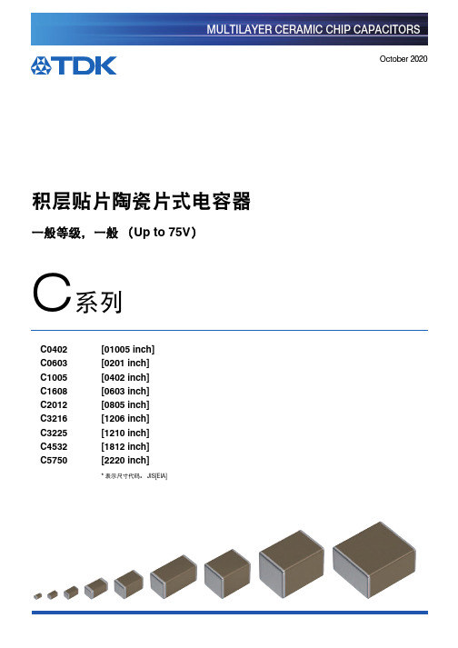
积层贴片陶瓷片式电容器商品说明书
此外,对使用本产品目录中所记载产品的设备进行设计时,请确保符合该设备的使用用途及状态的保护回路和装置,并设置备用回路等。 2. 本产品目录中记载的产品因改良及其他原因可能在不经预告的情况下进行变更或停止供应。 3. 关于本产品目录中记载的产品,本公司备有记载了各产品的规格及安全注意事项的 “ 交货规格书 ”。在选用产品时,建议签定交货规格
(例)
产品目录发行日期 2012 年12 月以前 2013 年1 月及以后
目录型号 C1608C0G1E103J(080AA) C1608C0G1E103J080AA
交货型号(交货标签上的标识) C1608C0G1E103JT000N C1608C0G1E103JT000N
20201025 / mlcc_commercial_general_zh.fm
长度 0.40 0.60 1.00 1.60 2.00 3.20 3.20 4.50 5.70
宽度 0.20 0.30 0.50 0.80 1.25 1.60 2.50 3.20 5.00
端子宽度 0.07 0.10 0.10 0.20 0.20 0.20 0.20 0.20 0.20
(3)温度特性
■系列概要
TDK积层陶瓷贴片电容器的C系列,是由诱电体材料以及内部电极、导电材料相互积层的表面贴装 (SMD)产品。单片式结构保证优异的机械强 度和高可靠性。 又因其简单的构造,跟其他种类电容相比具有更低的ESR、 ESL,频率特性良好。目前可以做到100uF的大容量,满足薄膜电容和电解电容的容 量领域。
C0G CH
JB
1C 1C 1C 1A 0J (16V) (16V) (16V) (10V) (6.3V)
0G (4V)
标准厚度 0.20 mm
0402C中文资料
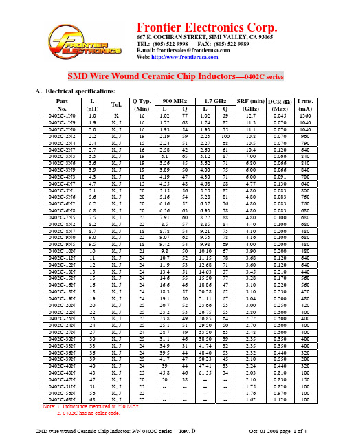
E-mail: frontiersales@ Web: SMD Wire Wound Ceramic Chip Inductors—0402C seriesA. Electrical specifications:900 MHz 1.7 GHz Part No. L (nH)Tol.Q Typ. (Min) L Q L Q SRF (min) (GHz)DCR (Ω) (Max) I rms.(mA) 0402C-1N0 1.0 K 16 1.02 77 1.02 6912.7 0.045 13600402C-1N9 1.9 K, J 16 1.72 68 1.74 82 11.3 0.070 1040 0402C-2N0 2.0 K, J 16 1.93 54 1.93 75 11.1 0.070 1040 0402C-2N2 2.2 K, J 19 2.19 59 2.23 100 10.8 0.070 960 0402C-2N4 2.4 K, J 15 2.24 51 2.27 68 10.5 0.070 790 0402C-2N7 2.7 K, J 16 2.58 42 2.60 61 10.4 0.120 640 0402C-3N3 3.3 K, J 19 3.1 65 3.12 87 7.00 0.066 840 0402C-3N6 3.6 K, J 19 3.56 45 3.62 71 6.80 0.066 840 0402C-3N9 3.9 K, J 19 3.89 50 4.00 75 6.00 0.066 840 0402C-4N3 4.3 K, J 18 4.19 47 4.30 71 6.00 0.091 700 0402C-4N7 4.7 K, J 15 4.55 48 4.68 68 4.77 0.130 640 0402C-5N1 5.1 K, J 20 5.15 56 5.25 82 4.80 0.083 800 0402C-5N6 5.6 K, J 20 5.16 54 5.28 81 4.80 0.083 760 0402C-6N2 6.2 K, J 20 6.16 52 6.37 76 4.80 0.083 760 0402C-6N8 6.8 K, J 20 6.56 63 6.93 78 4.80 0.083 680 0402C-7N5 7.5 K, J 22 7.91 60 8.22 88 4.80 0.100 680 0402C-8N2 8.2 K, J 22 8.5 57 8.85 84 4.40 0.100 680 0402C-8N7 8.7 K, J 18 8.78 54 9.21 73 4.10 0.200 480 0402C-9N0 9.0 K, J 22 9.07 62 9.53 78 4.16 0.100 680 0402C-9N5 9.5 K, J 18 9.42 54 9.98 69 4.00 0.200 480 0402C-10N 10 K, J 21 9.8 50 10.10 67 3.90 0.200 480 0402C-11N 11 K, J 24 10.7 52 11.15 78 3.68 0.120 640 0402C-12N 12 K, J 24 11.9 53 12.68 71 3.60 0.120 640 0402C-13N 13 K, J 24 13.4 51 14.63 57 3.45 0.210 440 0402C-15N 15 K, J 24 14.6 55 15.50 77 3.28 0.170 560 0402C-16N 16 K, J 24 16.6 46 18.86 47 3.10 0.220 560 0402C-18N 18 K, J 24 18.3 57 20.28 62 3.10 0.230 420 0402C-19N 19 K, J 24 19.1 50 21.11 67 3.04 0.200 480 0402C-20N 20 K, J 25 20.7 52 23.66 53 3.00 0.250 420 0402C-22N 22 K, J 25 23.2 53 26.75 53 2.80 0.300 400 0402C-23N 23 K, J 22 23.8 49 26.85 64 2.72 0.300 400 0402C-24N 24 K, J 25 25.1 51 29.50 50 2.70 0.300 400 0402C-27N 27 K, J 24 28.7 49 33.50 63 2.48 0.300 400 0402C-30N 30 K, J 25 31.1 46 38.50 39 2.35 0.350 400 0402C-33N 33 K, J 24 34.9 31 41.74 32 2.35 0.350 400 0402C-36N 36 K, J 24 39.5 44 48.40 53 2.32 0.440 320 0402C-39N 39 K, J 25 41.7 47 50.23 45 2.10 0.550 200 0402C-40N 40 K, J 24 39 44 47.41 33 2.24 0.440 320 0402C-43N 43 K, J 25 45.8 46 61.55 34 2.03 0.810 100 0402C-47N 47 K, J 20 50 38 -- -- 2.10 0.830 150 0402C-51N 51 K, J 25 -- -- -- -- 1.75 0.820 100 0402C-56N 56 K, J 22 -- -- -- -- 1.76 0.970 100 0402C-68N 68 K, J 22 -- -- -- -- 1.62 1.120 100Note: 1. Inductance measured at 250 MHz2. 0402C has no color code.E-mail: frontiersales@ Web: SMD Wire Wound Ceramic Chip Inductors—0402C seriesB. Dimensions: (Unit: mm)SERIES A (Max.) B (Max.)C (Max.)D (Max.)E F0402C 1.27 0.76 0.61 0.46 0.50 0.66C. Mechanical Drawing:D. General information:1. Tolerance: K: ± 10%, J: ± 5%, G: ± 2%.2. Small and lightweight surface mounting type.3. High Q at high frequency.4. High self-resonance frequency.5. For 15ºC Temperature Rise at 25ºC ambient.6. Inductance & Q measured using the HP4291B.7. SRF measured using the HP8720D or HP8753E.8. DCR measured using the 502BC.9. Operating temperature: -40°C TO +125ºC.10. This series has no color code due to the size is small. 11. Inductance Range:• 0402C (Ceramic) Series: 1.0nH (1360mA)∼68nH (100mA). SRF from 12.7GHz to 1.62GHz. 12. RoHS compliant.E. Applications:Ä Pagers. Ä Mobile communication units. Ä Portable telephone. Ä Hybrid.Ì Special specifications are available for customer’s requirement.Land Pattern0.560.230.23Web: SMD Wire Wound Ceramic Chip Inductors—0402C seriesF.Characteristic curve:1.Inductance vs. Frequency:2.Typical Q vs. Frequency:E-mail: frontiersales@ Web: SMD Wire Wound Ceramic Chip Inductors—0402C seriesF. Paper Tape1. Reel Dimension:2. Paper Tape Specification:A B K F P Po P1 W Quantity 0.80 1.22 0.60 3.5 2.0 4.0 2.0 8.0 4,0003. Emboss Plastic Tape Specification:A B C D E F G H IQuantity 8 0.71 2.0 1.16 3.5 1.75 2 0.65 0.23 4,0004. Cover Tape Strength:The force for tearing off cover tape is 0.1~0.6(N) in the arrow direction at the following conditions: a. Temperature : 5 ~ 35ºC. b. Humidity : 45 ~ 85%. c. Atmospheric pressure : 860 ~ 1060 hpa。
Vishay 反冲高功率厚膜片电阻说明书

RCS040210K0JNE D RCS040210R0FKEDRCS040220K0FKEDRCS0603100RFKEARCS0603150RFKEARCS e3VishayAnti-Surge, High Power Thick Film Chip ResistorsLINKS TO ADDITIONAL RESOURCESThe anti-surge thick film chip resistor series combines a significantly higher power rating and pulse load performance as compared to standard chip resistors.FEATURES•Excellent surge pulse capability •Superior ESD surge characteristics •High power rating •AEC-Q200 qualified•Material categorization: for definitions of compliance please see /doc?99912APPLICATIONS•Automotive •Industrial•Telecommunications •MedicalNote(1)Please refer to APPLICATION INFORMATION belowAPPLICATION INFORMATIONWhen the resistor dissipates power, a temperature rise above the ambient temperature occurs, dependent on the thermal resistance of the assembled resistor together with the printed circuit board. The rated dissipation applies only if the permitted film temperature is not exceeded.These resistors do not feature a limited lifetime when operated within the permissible limits. However, resistance value drift increasing over operating time may result in exceeding a limit acceptable to the specific application, thereby establishing afunctional lifetime.3D 3D3D ModelsTECHNICAL SPECIFICATIONSDESCRIPTION RCS0402 e3RCS0603 e3RCS0805 e3RCS1206 e3Imperial size 0402060308051206Metric size code RR1005MRR1608MRR2012MRR3126MResistance range 1 Ω to 10 M Ω; jumper (0 Ω)Resistance tolerance ± 5 %; ± 1 %; ± 0.5 %Temperature coefficient ± 200 ppm/K; ± 100 ppm/K Rated dissipation, P 70 (1)0.2 W 0.25 W 0.5 W 0.5 W Operating voltage, U max. AC RMS /DC 50 V 75 V150 V200 VPermissible film temperature, ϑF max. (1)155 °C Operating temperature range -55 °C to +155 °CMax. resistance change at P 70 for resistance range, |ΔR /R | after:1000 h ≤ 1.0 %8000 h≤ 2.0 %Permissible voltage against ambient (insulation):1 min, U ins75 V100 V200 V300 VFailure rate: FIT observed≤ 0.1 x 10⁻⁹/hRCS e3VishayNote•The temperature coefficient of resistance (TCR) is not specified for 0 Ω jumpersTEMPERATURE COEFFICIENT AND RESISTANCE RANGETYPE / SIZETCR TOLERANCERESISTANCE E-SERIES RCS0402 e3± 200 ppm/K± 5 % 1 Ω to 10 M ΩE24± 100 ppm/K ± 1 % 1 Ω to 10 M ΩE24; E96± 100 ppm/K ± 0.5 % 1 Ω to 10 M ΩE24; E96Jumper, I max. = 3 A ≤ 20 m Ω0 Ω-RCS0603 e3± 200 ppm/K± 5 % 1 Ω to 10 M ΩE24± 100 ppm/K ± 1 % 1 Ω to 10 M ΩE24; E96± 100 ppm/K ± 0.5 % 1 Ω to 10 M ΩE24; E96Jumper, I max. = 3.5 A≤ 20 m Ω0 Ω-RCS0805 e3± 200 ppm/K± 5 % 1 Ω to 10 M ΩE24± 100 ppm/K ± 1 % 1 Ω to 10 M ΩE24; E96± 100 ppm/K ± 0.5 % 1 Ω to 10 M ΩE24; E96Jumper, I max. = 4 A ≤ 20 m Ω0 Ω-RCS1206 e3± 200 ppm/K± 5 % 1 Ω to 10 M ΩE24± 100 ppm/K ± 1 % 1 Ω to 10 M ΩE24; E96± 100 ppm/K ± 0.5 % 1 Ω to 10 M ΩE24; E96Jumper, I max. = 5 A≤ 20 m Ω0 Ω-PACKAGINGTYPE / SIZE CODE QUANTITY PACKAGING STYLEWIDTHPITCH PACKAGING DIMENSIONS RCS0402 e3ED = ET710 000Paper tape according to IEC 60286-3, Type 1a8 mm2 mmØ 180 mm/7"EE = EF450 000Ø 330 mm/13"RCS0603 e3EI = ET25000 2 mmØ 180 mm/7"ED = ET310 000Ø 180 mm/7"EL = ET420 000Ø 285 mm/11.25"EE = ET850 000Ø 330 mm/13"EA = ET15000 4 mm Ø 180 mm/7"EB = ET510 000Ø 285 mm/11.25"EC = ET620 000Ø 330 mm/13"RCS0805 e3EA = ET15000 4 mmØ 180 mm/7"EB = ET510 000Ø 285 mm/11.25"EC = ET620 000Ø 330 mm/13"RCS1206 e3EA = ET15000 4 mm Ø 180 mm/7"EB = ET510 000Ø 285 mm/11.25"EC = ET620 000Ø 330 mm/13"RCS e3 VishayPART NUMBER AND PRODUCT DESCRIPTIONPart Number: RCS0805100RFKECPart Number: RCS08050000Z0ECTYPE / SIZE RESISTANCE TOLERANCE TCR PACKAGINGRCS0402 RCS0603 RCS0805 RCS1206R = decimalK = thousandM = million0000 = jumperD = ± 0.5 %F = ± 1.0 %J = ± 5.0 %Z = jumperK = ± 100 ppm/KN = ± 200 ppm/K0 = jumperEA, EB,EC, ED,EE, EI,ELProduct Description: RCS0805 100 100R 1 % ET6 e3Product Description: RCS0805 0R0 ET6 e3RCS0805100100R 1 %ET6e3 TYPE / SIZE TCR RESISTANCE TOLERANCE PACKAGING LEAD (Pb)-FREERCS0402 RCS0603 RCS0805 RCS1206± 100 ppm/K± 200 ppm/K10R = 10 Ω100R = 100 Ω10K = 10 kΩ1M0 = 1 MΩ0R0 = jumper± 0.5 %± 1.0 %± 5.0 %ET1, ET2,ET3, ET4,ET5, ET6,ET7, ET8,EF4e3 = pure tintermination finishR C S085100R F K E CRCS e3 VishayDESCRIPTIONProduction is strictly controlled and follows an extensive set of instructions established for reproducibility. A cermet film layer and a glass-over are deposited on a high grade (AI2O3) ceramic substrate with its prepared inner contacts on both sides. A special laser is used to achieve the target value and the desired power dissipation performance by smoothly fine trimming the resistive layer without damaging the ceramics. The resistor elements are covered by a protective coating designed for electrical, mechanical and climatic protection. The terminations receive a final pure matte tin on nickel plating.The result of the determined production is verified by an extensive testing procedure on 100 % of the individual chip resistors. Only accepted products are laid directly into the tape in accordance with IEC 60286-3 Type 1a (1). ASSEMBLYThe resistors are suitable for processing on automatic SMD assembly systems. They are suitable for automatic soldering using wave, reflow or vapor phase as shown in IEC 61760-1. The encapsulation is resistant to all cleaning solvents commonly used in the electronics industry, including alcohols, esters and aqueous solutions. The suitability of conformal coatings potting compounds and their processes, if applied, shall be qualified by appropriate means to ensure the long-term stability of the whole system. The resistors are RoHS-compliant, the pure matte tin plating provides compatibility with lead (Pb)-free and lead-containing soldering processes. Solderability is specified for 2 years after production or requalification. The permitted storage time is 20 years. The immunity of the plating against tin whisker growth has been proven under extensive testing.MATERIALSVishay acknowledges the following systems for the regulation of hazardous substances:•IEC 62474, Material Declaration for Products of and for the Electrotechnical Industry, with the list of declarable substances given therein (2)•The Global Automotive Declarable Substance List (GADSL) (3)•The REACH regulation (1907/2006/EC) and the related list of substances with very high concern (SVHC) (4) for its supply chain The products do not contain any of the banned substances as per IEC 62474, GADSL, or the SVHC list, see /how/leadfree.Hence the products fully comply with the following directives:•2000/53/EC End-of-Life Vehicle Directive (ELV) and Annex II (ELV II)•2011/65/EU Restriction of the Use of Hazardous Substances Directive (RoHS) with amendment 2015/863/EU•2012/19/EU Waste Electrical and Electronic Equipment Directive (WEEE)Vishay pursues the elimination of conflict minerals from its supply chain, see the Conflict Minerals Policy at /doc?49037.APPROVALSThe resistors are qualified according to AEC-Q200.Where applicable, the resistors are tested in accordance with EN 140401-802 which refers to EN 60115-1, EN 60115-8 and the variety of environmental test procedures of the IEC 60068 (1) series.RELATED PRODUCTSF or more information about products with superior surge and pulse performance please refer to D/CRCW-IF e3, Pulse Proof Thick F ilm Chip Resistors datasheet (/doc?20024).The CRCW-HP e3 product series is designed for those applications where both enhanced power rating and superior pulse loading performance is required.For ordering CRCW-HP e3 please refer to latest edition of datasheet (/doc?20043).For thick film resistors with standard requirements for power rating, please refer to D/CRCW e3, Standard Thick Film Chip Resistors datasheet (/doc?20035)Notes(1)The quoted IEC standards are also released as EN standards with the same number and identical contents(2)The IEC 62474 list of declarable substances is maintained in a dedicated database, which is available at http://std.iec.ch/iec62474.(3)The Global Automotive Declarable Substance List (GADSL) is maintained by the American Chemistry Council and available at (4)The SVHC list is maintained by the European Chemical Agency (ECHA) and available at http://echa.europa.eu/candidate-list-tableRCS e3VishayFUNCTIONAL PERFORMANCESingle Pulse High Power Overload 1.2 μs / 50 μs PulsePulse load rating in accordance with EN 60115-1, 4.27; 1.2 μs / 50 μs;5 pulses at 12 s intervals; for permissible resistance change 1 %Single Pulse High Power Overload 10 μs / 700 μs PulsePulse load rating in accordance with EN 60115-1, 4.27; 10 μs / 700 μs;10 pulses at 1 min intervals; for permissible resistance change 1 %Single PulseMaximum pulse load, single pulse; applicable if P → 0 and n < 1000 and = max.;for permissible resistance change equivalent to 8000 h operation110100100010 000110100100010 000100 000P e a k V o l t a g e (V )Resistance Value (Ω)110100100010 000110100100010 000100 000P e a k V o l t a g e (V )Resistance Value (Ω)0.010.1110100100010 0000.0000010.000010.00010.0010.010.1110100^P m a x .-P u l s e L o a d (W )t i -Pulse Duration (s)U ˆU ˆRCS e3VishayContinuous PulseMaximum pulse load, continuous pulses; applicable if P ≤ P (ϑamb ) and = max.;for permissible resistance change equivalent to 8000 h operationPulse VoltageMaximum pulse voltage, single and continuous pulses; applicable if = max.;for permissible resistance change equivalent to 8000 h operationDerating0.010.1110100100010 0000.0000010.000010.00010.0010.010.1110100^P m a x .-P u l s e L o a d (W )t i -Pulse Duration (s)U ˆU ˆ02004006008000.0000010.000010.00010.0010.010.1110^U m a x .-P u l s e V o l t a g e (V )t i-Pulse Duration (s)PˆP ˆ00.10.20.30.40.50.6P -P o w e r D i s s i p a t i o n (W )ϑamb -Ambient Temperature (°C)RCS e3VishayTESTS AND REQUIREMENTSAll executed tests are carried out in accordance with the following specifications:EN 60115-1, generic specificationEN 60115-8 (successor of EN 140400), sectional specificationEN 140401-802, detail specification IEC 60068-2-xx, test methodsThe parameters stated in the Test Procedures and Requirements table are based on the required tests and permitted limits of EN 140401-802. The table presents only the most important tests, for the full test schedule refer to the documents listed above. However, some additional tests and a number of improvements against those minimum requirements have been included.The testing also covers most of the requirements specified by EIA/IS-703 and JIS-C-5201-1.The tests are carried out under standard atmospheric conditions in accordance with IEC 60068-1, 4.3, whereupon the following values are applied:Temperature: 15 °C to 35 °C Relative humidity: 25 % to 75 %Air pressure: 86 kPa to 106 kPa (860 mbar to 1060 mbar).A climatic category LCT / UCT / 56 is applied, defined by the lower category temperature (LCT), the upper category temperature (UCT), and the duration of exposure in the damp heat, steady state test (56 days).The components are mounted for testing on boards in accordance with EN 60115-8, 2.4.2 unless otherwise specified.TEST PROCEDURES AND REQUIREMENTSEN60115-1 CLAUSE IEC 60068-2 (1)TEST METHODTESTPROCEDUREREQUIREMENTS PERMISSIBLECHANGE (ΔR )STABILITY CLASS 1OR BETTER STABILITY CLASS 2OR BETTERStability for product types:1 Ω to 10 M ΩRCS e34.5-Resistance -± 0.5 %; ± 1 %± 5 %4.8-Temperature coefficientAt (20 / -55 / 20) °C and(20 / 155 / 20) °C± 100 ppm/K± 200 ppm/K4.25.1-Endurance at 70 °CU = or U = U max. whichever is the less severe;1.5 h on; 0.5 h off 70 °C; 1000 h ± (1 % R + 0.05 Ω)± (2 % R + 0.1 Ω)70 °C; 8000 h± (2 % R + 0.1 Ω)± (4 % R + 0.1 Ω)4.25.3-Endurance at upper category temperature 155 °C; 1000 h± (1 % R + 0.05 Ω)± (2 % R + 0.1 Ω)4.2478 (Cab)Damp heat, steady state (40 ± 2) °C; 56 days;(93 ± 3) % RH± (1 % R + 0.05 Ω)4.3767 (Cy)Damp heat, steady state,accelerated (85 ± 2) °C; (85 ± 5) % RH U = ≤ 100 V;1000 h ± (1 % R + 0.05 Ω)± (2 % R + 0.1 Ω)4.23-Climatic sequence:± (1 % R + 0.05 Ω)± (2 % R + 0.1 Ω)4.23.2 2 (Bb)Dry heat 125 °C; 16 h4.23.330 (Db)Damp 55 °C; 24 h; ≥ 90 % RH; 1 cycle4.23.4 1 (Ab)Cold-55 °C; 2 h4.23.513 (M)Low air pressure 8.5 kPa; 2 h; (25 ± 10) °C4.23.630 (Db)Damp heat, cyclic55 °C; 24 h;≥ 90 % RH; 5 cycles 4.23.7-DC load U = ≤ U max.; 1 min- 1 (Aa)Cold -55 °C; 2 h± (0.25 % R + 0.05 Ω)± (0.5 % R + 0.05 Ω)4.1914 (Na)Rapid change of temperature 30 min. at -55 °C and 30 min. at 125 °C 1000 cycles± (1 % R + 0.05 Ω)no visible damage 4.13-Short time overloadU = 2.5 x ≤ 2 x U max.;whichever is the less severe; 5 s± (2 % R + 0.05 Ω)4.27-Single pulsehigh voltage overload Severity no. 4:U = 10 x or U = 2 x U max.;whichever is the less severe;10 pulses 10 μs / 700 μs± (1 % R + 0.05 Ω)no visible damageP 70 x R 0.1 x P 85 x R P 70 x R P 70 x R P 70 x RRCS e3VishayNote(1)The quoted IEC standards are also released as EN standards with the same number and identical contents4.39-Periodic electric overloadU = orU = 2 x U max.;whichever is the less severe;0.1 s on; 2.5 s off;1000 cycles ± (1 % R + 0.05 Ω)no visible damage4.38-Electrostatic discharge (human body model)IEC 61340-3-1 (1);3 positive + 3 negative discharges;ESD voltage according to the size± (1 % R + 0.05 Ω)4.22 6 (Fc)VibrationEndurance by sweeping;10 Hz to 2000 Hz;no resonance;amplitude ≤ 1.5 mm or ≤ 200 m/s 2;7.5 h± (0.25 % R + 0.05 Ω)no visible damage ± (0.5 % R + 0.05 Ω)no visible damage4.1758 (Td)SolderabilitySolder bath method,SnPb40; non-activated flux (235 ± 5) °C; (2 ± 0.2) s Good tinning (≥ 95 % covered);no visible damageSolder bath method,Sn96.5Ag3Cu0.5; non-activated flux (245 ± 5) °C; (3 ± 0.3) s 4.1858 (Td)Resistance to soldering heat Soldering bath method;(260 ± 5) °C; (10 ± 1) s ± (0.25 % R + 0.05 Ω)± (0.5 % R + 0.05 Ω)4.2945 (XA)Component solventresistance Isopropyl alcohol +50 °C;method 2No visible damage 4.3221 (Ue 3)Shear (adhesion)RCS0402 e3: 9 NRCS0603 e3 to RCS1206 e3: 17.7 NNo visible damage 4.3321 (Ue 1)Substrate bending Depth 2 mm; 3 times ± (0.25 % R + 0.05 Ω)no visible damage,no open circuit in bent position 4.7-Voltage proof U = 1.4 x U ins ; 60 s No flashover or breakdown4.35-Flammability,needle flame testIEC 60695-11-5 (1);10 sNo burning after 30 sTEST PROCEDURES AND REQUIREMENTSEN60115-1 CLAUSEIEC 60068-2 (1)TEST METHODTESTPROCEDUREREQUIREMENTS PERMISSIBLECHANGE (ΔR )STABILITY CLASS 1OR BETTER STABILITY CLASS 2OR BETTERStability for product types:1 Ω to 10 M ΩRCS e315 x P 70 x RRCS e3VishayDIMENSIONSSOLDER PAD DIMENSIONSNotes•The given solder pad dimensions reflect the considerations for board design and assembly as outlined e.g in standards IEC 61188-5-x (1) or in publication IPC-7351(1)The quoted IEC standards are also released as EN standards with the same number and identical contentsDIMENSIONS AND MASSTYPE / SIZE L (mm)W (mm)H (mm)T1(mm)T2(mm)MASS (mg)RCS0402 e3 1.0 ± 0.050.5 ± 0.050.35 ± 0.050.25 ± 0.100.2 ± 0.100.65RCS0603 e3 1.55 + 0.10 / - 0.050.85 ± 0.100.45 ± 0.050.3 ± 0.200.3 ± 0.202RCS0805 e3 2.0 + 0.20 / - 0.10 1.25 ± 0.150.45 ± 0.050.3 + 0.20 / - 0.100.3 ± 0.20 5.5RCS1206 e33.2 + 0.10 / - 0.201.6 ± 0.150.55 ± 0.100.45 ± 0.200.4 ± 0.2010RECOMMENDED SOLDER PAD DIMENSIONSTYPE / SIZEWAVE SOLDERINGREFLOW SOLDERING G (mm)Y (mm)X (mm)Z (mm)G (mm)Y (mm)X (mm)Z (mm)RCS0402 e3----0.450.60.6 1.65RCS0603 e30.65 1.10 1.252.850.750.75 1.00 2.25RCS0805 e30.90 1.30 1.603.50 1.000.95 1.45 2.90RCS1206 e31.401.401.954.201.501.051.803.60HLegal Disclaimer Notice VishayDisclaimerALL PRODU CT, PRODU CT SPECIFICATIONS AND DATA ARE SU BJECT TO CHANGE WITHOU T NOTICE TO IMPROVE RELIABILITY, FUNCTION OR DESIGN OR OTHERWISE.Vishay Intertechnology, Inc., its affiliates, agents, and employees, and all persons acting on its or their behalf (collectively,“Vishay”), disclaim any and all liability for any errors, inaccuracies or incompleteness contained in any datasheet or in any other disclosure relating to any product.Vishay makes no warranty, representation or guarantee regarding the suitability of the products for any particular purpose or the continuing production of any product. To the maximum extent permitted by applicable law, Vishay disclaims (i) any and all liability arising out of the application or use of any product, (ii) any and all liability, including without limitation special, consequential or incidental damages, and (iii) any and all implied warranties, including warranties of fitness for particular purpose, non-infringement and merchantability.Statements regarding the suitability of products for certain types of applications are based on Vishay's knowledge of typical requirements that are often placed on Vishay products in generic applications. Such statements are not binding statements about the suitability of products for a particular application. It is the customer's responsibility to validate that a particular product with the properties described in the product specification is suitable for use in a particular application. Parameters provided in datasheets and / or specifications may vary in different applications and performance may vary over time. All operating parameters, including typical parameters, must be validated for each customer application by the customer's technical experts. Product specifications do not expand or otherwise modify Vishay's terms and conditions of purchase, including but not limited to the warranty expressed therein.Hyperlinks included in this datasheet may direct users to third-party websites. These links are provided as a convenience and for informational purposes only. Inclusion of these hyperlinks does not constitute an endorsement or an approval by Vishay of any of the products, services or opinions of the corporation, organization or individual associated with the third-party website. Vishay disclaims any and all liability and bears no responsibility for the accuracy, legality or content of the third-party website or for that of subsequent links.Except as expressly indicated in writing, Vishay products are not designed for use in medical, life-saving, or life-sustaining applications or for any other application in which the failure of the Vishay product could result in personal injury or death. Customers using or selling Vishay products not expressly indicated for use in such applications do so at their own risk. Please contact authorized Vishay personnel to obtain written terms and conditions regarding products designed for such applications. No license, express or implied, by estoppel or otherwise, to any intellectual property rights is granted by this document or by any conduct of Vishay. Product names and markings noted herein may be trademarks of their respective owners.© 2023 VISHAY INTERTECHNOLOGY, INC. ALL RIGHTS RESERVEDRevision: 01-Jan-20231Document Number: 91000RCS06033K30FKE A RCS06034K70FKEARCS08051K00FKEARCS040210K0JNE D RCS040210R0FKEDRCS040220K0FKEDRCS0603100RFKEARCS0603150RFKEA。
华世科IC简介new
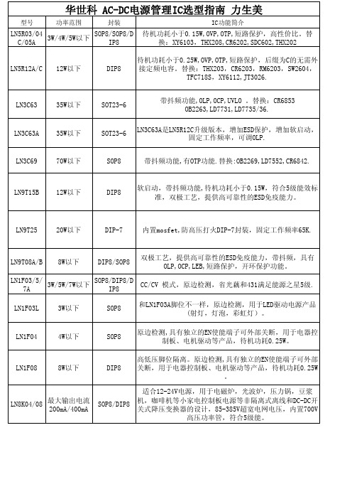
华世科 AC-DC电源管理IC选型指南 力生美型号功率范围封装IC功能简介LN5R03/04 C/05A 3W/4W/5W以下SOP8/SOP8/DIP8待机功耗小于0.15W,OVP,OTP,短路保护,高性价比。
替换:XY6103,THX208,CR6202,SDC602,THX202LN5R12A/C12W以下DIP8待机功耗小于0.25W,OVP,OTP,短路保护,后缀为C的无需外接定频电容。
替换:THX203,CR6203,RM6203,SW2604,TFC718S,XY6112,JT3026.LN3C6335W以下SOT23-6带抖频功能,OLP,OCP,UVLO 。
替换:CR6853 OB2263,LD7731,LD7735/36.LN3C63A35W以下SOT23-6LN3C63A是LN5R12C升级版本,增加ESD保护,增加软启动,固定工作频率,可调OLP.LN3C6970W以下SOP8带抖频功能,有OTP功能.替换:OB2269,LD7552,CR6842.LN9T15B12W以下DIP8软启动,带抖频功能,待机功耗小于0.15W,符合5级能效标准,双极工艺,提供高可靠性的ESD免疫能力。
LN9T2520W以下DIP-7内置mosfet,防高压打火DIP-7封装,固定工作频率65K.LN9T08A/B8W以下DIP8/SOP8双极工艺,提供高可靠性的ESD免疫能力,带抖频,具有OLP,OCP,LEB,短路保护,开环保护功能。
LN1F03/5/7A 3W/5W/7W以下SOP8/DIP8/DIP8CC/CV 模式,原边检测,省光藕和431满足能源之星5级.LN1F03L3W以下SOP8和LN1F03A脚位不一样,原边检测,用于LED驱动电源产品(射灯,灯泡,彩虹灯)。
LN1F044W以下SOP8原边检测,具有独立的EN使能端子可外部关断,用于电器控制板、电机驱动等产品,待机功耗0.25W。
南京国春电气设备 (GC-04 GC-04-DIP GC-04-DIP-SMA)蓝牙模块 数据手册
蓝牙模块数据手册(GC-04/ GC-04-DIP/GC-04-DIP-SMA)(GC-06)南京国春电气设备有限公司2009.5型号:GC-04 CLASS2贴片式蓝牙模块1、产品概述GC-04蓝牙模块,设计采用了CSR公司的AUDIO –FLASH蓝牙芯片,外围主要元器件选型采用工业级标准,模块电路板为0.8mm四层板,采用激光盲孔加工工艺,引脚采用半孔加工工艺,贴片式设计,体积尺寸紧凑,最适合工业数据、语音传输。
是高质量的CLASS2 蓝牙模块。
电路接口:USB口、RS232串行口(TTL电平)、Audio模拟语音接口(SPK,MIC),SPI编程口,2路AIO模拟量接口,12路数字PIO接口主要性能:频段:2.40GHz—2.48GHz ,ISM Band蓝牙协议:BlueTooth V1.2功率等级:Class2(+6dBm )接收灵敏度:-85dBm操作电压:2.7V~3.3V工作温度: -40℃至 +105℃参考功耗:待机 0 ~ 6 mA数据通信约20 mA语音通讯约30 mA典型应用:串口数据传输,最大波特率 1.3Mbps,工业级无线数据采集,一对一自动建链,透明串口;上传数据至PC、笔记本、PDA、智能手机等。
蓝牙语音传输,模块与模块蓝牙对讲,模块与普通蓝牙耳机,模块做为蓝牙耳机使用等。
蓝牙遥控,利用数字PIO实现远程无线遥控。
车载蓝牙、GPS蓝牙、蓝牙语音网关、用户可自行开发各种蓝牙应用。
GC-04蓝牙模块硬件框图:模块定制:用户可按需定制1.8V版GC-04;用户可定制特殊功能的蓝牙固件;用户可定制特殊外形的蓝牙模块;请提前进行技术交流。
2、引脚定义和外形尺寸(单位:mil 100mil=2.54mm)图2:GC-04模块引脚定义与外形尺寸(12.25mm×19.6mm)3、引脚描述PINNAME NAME NAME NO.1 GND GND Ground2 External Clock Analogue Input For External Clock Input3 AIO0 Analogue Input V oltage ADC Input(0V~1.8V)4 AIO1 Analogue Input V oltage ADC Input(0V~1.8V)5 USB_DN Bi-directional USB Data Minus6 USB_DP Bi-directional USB Data Plus7 UART_TXD CMOS Output UART Data Output (Active High)8 UART_RXD CMOS Input UART Data Input (Active High)9 UART_CTS CMOS Input UART Clear To Send (Active Low)10 UART_RTS CMOS Output UART Request To Send (Active Low)11 PIO4 Bi-directional Programmable Input/Output line12 GND GND Ground13 VCC Input Power Supply Input (1.8V or 3.0V)14 GND GND Ground15 PIO5 Bi-directional Programmable Input/Output line16 PIO6 Bi-directional Programmable Input / Output Line17 PIO7 Bi-directional Programmable Input / Output Line18 SPI_MOSI CMOS Input Serial Peripheral Interface Data Input19 SPI_CSB CMOS Input Chip Select For Synchronous Serial Interface20 SPI_CLK CMOS Input Serial Peripheral Interface Clock21 GND GND Ground22 SPI_MISO CMOS Output Serial Peripheral Interface Data Output23 RESET CMOS Input Reset (Active High)24 PIO8 Bi-directional Programmable Input/Output Line25 PIO9 Bi-directional Programmable Input/Output Line26 PIO10 Bi-directional Programmable Input/Output Line27 PIO11 Bi-directional Programmable Input/Output Line28 PIO3 Bi-directional Programmable Input/Output Line29 PIO2 Bi-directional Programmable Input/Output Line30 PIO1 Bi-directional Programmable Input/Output Line31 PIO0 Bi-directional Programmable Input/Output Line32 AUX_DAC Analogue Output V oltage DAC Output33 GND GND Ground34 RX_RF_IN Analogue Input Single-ended Receiver Input35 ANT ANT Antenna36 GND GND Ground37 SPK_P Analogue Output Speaker Output Positive38 SPK_N Analogue Output Speaker Output Negative39 MIC_N Analogue Input Microphone Input Negative40 MIC_P Analogue Input Microphone Input Positive4、天线参考设计:请参考相关PROTEL文档。
ACKU040 核心板用户手册说明书
KINTEX UltraScale开发平台用户手册ACKU040核心板2 / 24芯驿电子科技(上海)有限公司文档版本控制文档版本修改内容记录REV1.0创建文档目录文档版本控制 (2)一、ACKU040核心板 (4)(一)简介 (4)(二)FPGA芯片 (5)(三)DDR4 DRAM (5)(四)QSPI Flash (10)(五)时钟配置 (11)(六)LED灯 (12)(七)电源 (12)(八)结构图 (14)(九)连接器管脚定义 (14)3 / 244 / 24芯驿电子科技(上海)有限公司一、 ACKU040核心板(一) 简介ACKU040(核心板型号,下同)核心板,FPGA 芯片是基于XILINX 公司的XC7K325系列的XCKU040-2FFVA1156I 。
核心板使用了4片Micron 的1GB 的DDR4芯片MT40A512M16LY-062EIT,总的容量达4GB 。
另外核心板上也集成了2片128MBit 大小的QSPI FLASH ,用于启动存储配置和系统文件。
这款核心板的6个板对板连接器扩展出了359个IO ,其中BANK64和BANK65的104个IO 的电平是3.3V ,其它BANK 的IO 都是1.8V 。
另外核心板也扩展出了20对高速收发器GTH 接口。
对于需要大量IO 的用户,此核心板将是不错的选择。
而且IO连接部分,FPGA 芯片到接口之间走线做了等长和差分处理,并且核心板尺寸仅为80*60(mm ),对于二次开发来说,非常适合。
ACKU040核心板正面图5 / 24(二) FPGA 芯片核心板使用的是Xilinx 公司的KINTEX UltraSacale 芯片,型号为XCKU040-2FFVA1156I 。
速度等级为2,温度等级为工业级。
此型号为FFVA1156封装,1156个引脚,引脚间距为1.0mm 。
Xilinx KINTEX UltraSacale 的芯片命名规则如下图1-2-1所示:图1-2-1 KINTEX UltraSacale FPGA 型号命名规则定义其中FPGA 芯片XCKU040的主要参数如下所示:名称具体参数 逻辑单元Logic Cells 530,250 查找表(CLB LUTs) 242,400 触发器(CLB flip-flops) 484,800 Block RAM (Mb )大小 21.1 DSP 处理单元(DSP Slices )1,920 PCIe Gen3 x8 3GTH Transceiver20个,16.3Gb/s max速度等级 -2 温度等级工业级(三) DDR4 DRAM核心板上配有四片Micron(美光)的1GB 的DDR4芯片,型号为MT40A512M16LY-062EIT 。
C1210C472KGRACTU中文技术资料
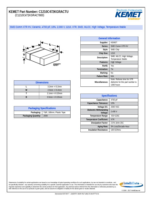
Packaging Specifications
Packaging: Packaging Quantity: T&R, 180mm, Plastic Tape 2000
Statements of suitability for certain applications are based on our knowledge of typical operating conditions for such applications, but are not intended to constitute - and we specifically disclaim - any warranty concerning suitability for a specific customer application or use. This Information is intended for use only by customers who have the requisite experience and capability to determine the correct products for their application. Any technical advice inferred from this Information or otherwise provided by us with reference to the use of our products is given gratis, and we assume no obligation or liability for the advice given or results obtained.
General Information
京瓷多联系列MLCC贴片电容规格书
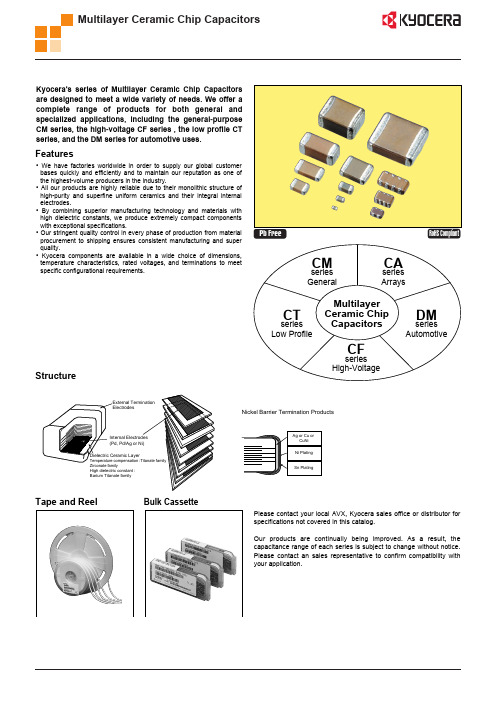
Pb Free
RoHS Compliant
series General
CM
series Arrays
CA
series Low Profile
CT
Multilayer Ceramic Chip Capacitors
series High-Voltage
series Automotive
DM
CF
Structure
Bulk Cassette
Size 05 105 21 EIA CODE 0402 0603 0805 EIAJ CODE 1005 1608 2012 L 1.00.05 1.60.07 2.00.1 W 0.50.05 0.80.07 1.250.1 T 0.50.05 0.80.07 1.250.1 P min. 0.15 0.20 0.20 max. 0.35 0.60 0.75 P to P min. 0.30 0.50 0.70
CAPACITANCE CODE
Capacitance expressed in pF. 2 significant digits plus number of zeros. For Values 10pF, Letter R denotes decimal point, eg. 100000pF 104 1.5pF 1R5 0.1F 104 0.5pF R50 4700pF 472 100F 107
CM CF CT DM General Purpose High Voltage Low Profile Automotive CA Capacitor Arrays
CM
21
X7R
104
K
C0402C6832RAC资料
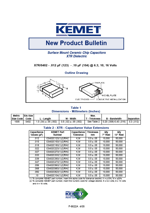
Surface Mount Ceramic Chip CapacitorsX7R DielectricX7R/0402 - .012 µF (123) - .10 µF (104) @ 6.3; 10; 16 VoltsMetricEIA Size Max.Size Code Code L - LengthW - WidthT - Thickness B - Bandwidth Separation 100504021.0 (.04) ± .05 (.002)0.5 (.02) ± .05 (.002)See Table 20.20 (.008)-0.40 (.016)0.3 (.012)Table 1Dimensions - Millimeters (Inches)New Product BulletinOutline DrawingF-9022A 4/05Table 2 - X7R - Capacitance Value ExtensionsCapacitance Values (µF)KEMET PartNumber Capacitance ToleranceThicknessmm Qty 7” Reel Qty 13” Reel .012C0402C123(1)(2)RAC K,M 0.5 ± .0510,00050,000.015C0402C153(1)(2)RAC K,M 0.5 ± .0510,00050,000.018C0402C183(1)(2)RAC K,M 0.5 ± .0510,00050,000.022C0402C223(1)(2)RAC K,M 0.5 ± .0510,00050,000.027C0402C273(1)(2)RAC K,M 0.5 ± .0510,00050,000.033C0402C333(1)(2)RAC K,M 0.5 ± .0510,00050,000.039C0402C393(1)(2)RAC K,M 0.5 ± .0510,00050,000.047C0402C473(1)(2)RAC K,M 0.5 ± .0510,00050,000.056C0402C563(1)(2)RAC K,M 0.5 ± .0510,00050,000.068C0402C683(1)(2)RAC K,M 0.5 ± .0510,00050,000.082C0402C823(1)(2)RAC K,M 0.5 ± .0510,00050,000.10C0402C104(1)(2)RACK,M0.5 ± .0510,00050,000(1) To complete KEMET part number, insert the alpha code for tolerance desired. K = ±10%; M = ±20%(2) To complete KEMET part number, insert the numeric code for voltage desired. 9 = 6.3 volts; 8 = 10 voltsand 4 = 16 volts.Electrical ParametersAs detailed in the KEMET Surface Mount Catalog F3102 for X7R, with following specific requirements based on room temperature (25°C) parameters:•Operating Range: -55°C to +125°C, with no-bias capacitance shift limited to ± 15% over that range •Insulation Resistance (IR) measured after 2 minutes at rated voltage @ 25°C: Limit is 500 megohm-microfarads•Capacitance and Dissipation Factor (DF) measured at 1KHz at 1.0Vrms. DF Limit for 6.3 and 10 volts is 5.0%. DF for 16 volt is 3.5%.Soldering ProcessThe 0402 components are suitable for reflow soldering only. All parts incorporate the standard KEMET barrier layer of pure nickel, with an overplate of pure tin to provide excellent solderability as well as resistance to leaching.MarkingThese chips are supplied unmarked.In general, the information in the KEMET Surface Mount catalog F3102 applies to these capacitors. The information in this bulletin supplements that in the catalog.© KEMET Electronics Corporation • P.O. Box 5928 • Greenville, SC 29606 • (864) 963-6300 • 。
STC12C5A60S2单片机元件清单
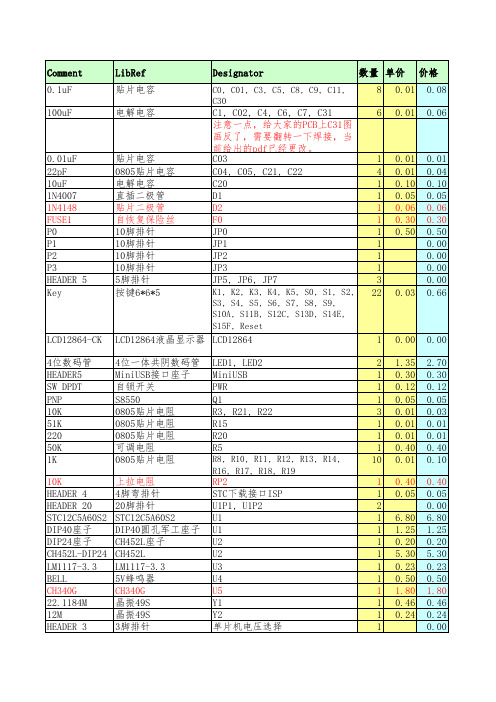
0.00 1.35 0.30 0.12 0.05 0.01 0.01 0.01 0.40 0.01 0.40 0.05 6.80 1.25 0.20 5.30 0.23 0.50 1.80 0.46 0.24 0.01 10.00
0.00 2.70 0.30 0.12 0.05 0.03 0.01 0.01 0.40 0.10 0.40 0.05 0.00 6.80 1.25 0.20 5.30 0.23 0.50 1.80 0.46 0.24 0.00 0.02 10.00.05 0.06 0.30 0.50 0.00 0.00 0.00 0.00 0.66
LCD12864-CK 4位数码管 HEADER5 SW DPDT PNP 10K 51K 220 50K 1K 10K HEADER 4 HEADER 20 STC12C5A60S2 DIP40座子 DIP24座子 CH452L-DIP24 LM1117-3.3 BELL CH340G 22.1184M 12M HEADER 3 跳线帽 单片机PCB
贴片电容 0805贴片电容 电解电容 直插二极管 贴片二极管 自恢复保险丝 10脚排针 10脚排针 10脚排针 10脚排针 5脚排针 按键6*6*5
C1, C02, C4, C6, C7, C31 注意一点,给大家的PCB上C31图 画反了,需要翻转一下焊接,当 前给出的pdf已经更改。 C03 C04, C05, C21, C22 C20 D1 D2 F0 JP0 JP1 JP2 JP3 JP5, JP6, JP7
RP2 STC下载接口ISP U1P1, U1P2 U1 U1 U2 U2 U3 U4 U5 Y1 Y2 单片机电压选择 用于选择VCC电压
Mini USB线
下载供电使用 合计
- 1、下载文档前请自行甄别文档内容的完整性,平台不提供额外的编辑、内容补充、找答案等附加服务。
- 2、"仅部分预览"的文档,不可在线预览部分如存在完整性等问题,可反馈申请退款(可完整预览的文档不适用该条件!)。
- 3、如文档侵犯您的权益,请联系客服反馈,我们会尽快为您处理(人工客服工作时间:9:00-18:30)。
Surface Mount Ceramic Chip Capacitors
X7R Dielectric
X7R/0402 - .012 µF (123) - .10 µF (104) @ 6.3; 10; 16 Volts
Metric
EIA Size Max.
Size Code Code L - Length
W - Width
T - Thickness B - Bandwidth Separation 10050402
1.0 (.04) ± .05 (.002)
0.5 (.02) ± .05 (.002)
See Table 2
0.20 (.008)-0.40 (.016)0.3 (.012)
Table 1
Dimensions - Millimeters (Inches)
New Product Bulletin
Outline Drawing
F-9022A 4/05
Table 2 - X7R - Capacitance Value Extensions
Capacitance Values (µF)
KEMET Part
Number Capacitance Tolerance
Thickness
mm Qty 7” Reel Qty 13” Reel .012C0402C123(1)(2)RAC K,M 0.5 ± .0510,00050,000.015C0402C153(1)(2)RAC K,M 0.5 ± .0510,00050,000.018C0402C183(1)(2)RAC K,M 0.5 ± .0510,00050,000.022C0402C223(1)(2)RAC K,M 0.5 ± .0510,00050,000.027C0402C273(1)(2)RAC K,M 0.5 ± .0510,00050,000.033C0402C333(1)(2)RAC K,M 0.5 ± .0510,00050,000.039C0402C393(1)(2)RAC K,M 0.5 ± .0510,00050,000.047C0402C473(1)(2)RAC K,M 0.5 ± .0510,00050,000.056C0402C563(1)(2)RAC K,M 0.5 ± .0510,00050,000.068C0402C683(1)(2)RAC K,M 0.5 ± .0510,00050,000.082C0402C823(1)(2)RAC K,M 0.5 ± .0510,00050,000.10
C0402C104(1)(2)RAC
K,M
0.5 ± .05
10,000
50,000
(1) To complete KEMET part number, insert the alpha code for tolerance desired. K = ±10%; M = ±20%
(2) To complete KEMET part number, insert the numeric code for voltage desired. 9 = 6.3 volts; 8 = 10 volts
and 4 = 16 volts.
Electrical Parameters
As detailed in the KEMET Surface Mount Catalog F3102 for X7R, with following specific requirements based on room temperature (25°C) parameters:
•Operating Range: -55°C to +125°C, with no-bias capacitance shift limited to ± 15% over that range •Insulation Resistance (IR) measured after 2 minutes at rated voltage @ 25°C: Limit is 500 megohm-microfarads
•Capacitance and Dissipation Factor (DF) measured at 1KHz at 1.0Vrms. DF Limit for 6.3 and 10 volts is 5.0%. DF for 16 volt is 3.5%.
Soldering Process
The 0402 components are suitable for reflow soldering only. All parts incorporate the standard KEMET barrier layer of pure nickel, with an overplate of pure tin to provide excellent solderability as well as resistance to leaching.
Marking
These chips are supplied unmarked.
In general, the information in the KEMET Surface Mount catalog F3102 applies to these capacitors. The information in this bulletin supplements that in the catalog.
© KEMET Electronics Corporation • P.O. Box 5928 • Greenville, SC 29606 • (864) 963-6300 • 。