Bongshin BS-5200显示仪表
Pepperl+Fuchs OBG5000-R100-2EP-IO 反射式传感器产品说明书

R e l e a s e d a t e : 2016-06-20 12:55D a t e o f i s s u e : 2016-06-20267075-100007_e n g .x m lT echnical dataG eneral specifications Effective detection range 0 ... 3.5 m in TEACH mode ; 0 ... 5 m at switch position "N"Reflector distance0 ... 3.5 m in TEACH mode ; 0 ... 5 m at switch position "N"Threshold detection range 6 mReference target H85-2 reflector Light source LEDLight typemodulated visible red light LED risk group labelling exempt groupDiameter of the light spot approx. 300 mm at a distance of 3.5 m Angle of divergence approx. 5 °Ambient light limitEN 60947-5-2Functional safety related parametersMTTF d 600 a Mission Time (T M ) 20 a Diagnostic Coverage (DC) 0 %Indicators/operating means Operation indicatorLED green:constantly on - power on flashing (4Hz) - short circuitflashing with short break (1 Hz) - IO-Link mode Function indicatorY ellow LED:Permanently lit—light path clear Permanently off—object detectedFlashing (4Hz)—operating reserve not reached Control elements T each-In keyControl elements5-step rotary switch for operating modes selection Contrast detection levels10 % - clean, water filled PET bottles 18 % - clear glass bottles40 % - colored glass or opaque materials Adjustable via rotary switchElectrical specifications Operating voltage U B 10 ... 30 V DC Ripplemax. 10 %No-load supply current I 0< 25 mA at 24 V supply voltage Protection class IIIInterfaceInterface type IO-Link ( via C/Q = BK )Transfer rate COM 2 (38.4 kBaud)IO-Link Revision 1.1Min. cycle time 2.3 msProcess data witdhProcess data input 2Bit Process data output 2Bit SIO mode support yesDevice ID0x110A01 (1116673)Compatible master port typeAOutputSwitching typeThe switching type of the sensor is adjustable. The default set-ting is:C/Q - BK: NPN normally open / dark-on, PNP normally closed / light-on, IO-Link/Q - WH: NPN normally closed / light-on, PNP normally open / dark-onSignal output 2 push-pull (4 in 1)outputs, short-circuit protected, reverse pola-rity protected, overvoltage protected Switching voltage max. 30 V DCSwitching current max. 100 mA , resistive load Usage category DC-12 and DC-13Voltage dropU d ≤ 1.5 V DC Switching frequency f500 Hz Response time1 msAmbient conditions Ambient temperature -20 ... 60 °C (-4 ... 140 °F) , movable cable not appropriate for conveyor chainsStorage temperature-40 ... 70 °C (-40 ... 158 °F)Mechanical specifications Degree of protection IP67 / IP69 / IP69K Connection 2 m fixed cableMaterial Housing PC (Polycarbonate)Optical face PMMA Mass approx. 36 g Cable length 2 m Compliance with standards and directi-vesDirective conformity EMC Directive 2004/108/EC EN 60947-5-2:2007+A1:2012Other suitable accessories can be found at AccessoriesV31-WM-2M-PURFemale cordset, M8, 4-pin, PUR cable V31-GM-2M-PURFemale cordset, M8, 4-pin, PUR cable REF-H85-2Reflector, rectangular 84.5mm x 84.5mm, mounting holesREF-H50Reflector, rectangular 51 mm x 61 mm, mounting holes, fixing strap REF-H33Reflector with screw fixingIO-Link-Master02-USBIO-Link master, supply via USB port or se-parate power supply, LED indicators, M12 plug for sensor connection OFR-100/100Reflective tape 100 mm x 100 mmR e l e a s e d a t e : 2016-06-20 12:55D a t e o f i s s u e : 2016-06-20267075-100007_e n g .x m lTeach-in:Use the rotary switch to select the required operating mode: Normal mode (N) or contrast level I – III.To teach in a threshold or activate an operating mode, press the "TI" button until the yellow and green LEDs flash in phase (approx. 1s).Release the "TI" button. T each-in starts.Successful teach-in is indicated by alternating flashing (2.5Hz) of the yellow and green LEDs. The sensor will now operate in the selected opera-ting mode with the taught-in threshold.An unsuccessful teach-in is indicated by rapidly alternating flashing (8Hz) of the yellow and green LEDs. After an unsuccessful teach-in, the sen-sor continues to operate with the previous valid setting after the relevant visual fault signal is issued.Every taught-in switching threshold can be re-taught (overwritten) by pressing the "TI" button again.Note: To ensure that the device functions reliably in Contrast mode, the device must be powered on at least 30s before Teach-in.Setting the Device to Maximum SensitivityUse the rotary switch to select the Normal mode (N) position.Press the "TI" button for >4s. The yellow and green LEDs will go out.Release the "TI" button.The settings will be reset to maximum sensitivity. After successfully resetting, the yellow and green LEDs will flash alternately (2.5Hz).Switching between light on/dark onUse the rotary switch to select the light on/dark on (L/D) position.Press the "TI" button for >1s.Standard conformityProduct standard EN 60947-5-2:2007+A1:2012 IEC 60947-5-2:2007 + A1:2012StandardsUL 60947-5-2: 2014 IEC 61131-9:2013 EN 62471:2008 EN 61131-9:2013Approvals and certificates UL approvalE87056 , cULus Listed , class 2 power supply , type rating 1Curves/DiagramsSettingsRelative received light strength in switch position "N"R e l e a s e d a t e : 2016-06-20 12:55D a t e o f i s s u e : 2016-06-20267075-100007_e n g .x m lT o reset the switching type, press the "TI" button for >4s.The respective operating indicator LED (L/D) will illuminate green and the operating indicator will be reset to the most recently active switching type.Reset to Default SettingsUse the rotary switch to select the O position.Press the "TI" button for >10s. The yellow and the green LEDs will both switch off.Release the "TI" button. The yellow LED is on.After resetting, the sensor will operate with the following default settings:•Normal mode (N)•Maximum sensitivity adjustment •Dark on•Pin 2 (white core): antivalent switching output。
Kuebler Codix 52U 电源驱动双功能计数器说明书

The Codix 52U is a voltage-powered dual function counter with 4 functions in one device:Counter with 2 totalizing ranges, totalizer and timer, totalizer and frequency meter, timer with 2 time ranges.F or fast and slow count pulses, with 6-digit LED display for NPN, PNP input signals.Order codea Input switching level0 = S tandard (HTL) 1) A = 4 ... 30 V DC1) Stock types6.52U .01.3X 20aDelivery specification · Counter· Mounting clip· Front bezel for screw mounting (T008181) 56 x 40 mm [2.20 x 1.57“], panel cut-out 50 x 25 mm [1.97 x 0.98“]· Front bezel for clip mounting (T008180) 53 x 28 mm [2.09 x 1.10“], panel cut-out 50 x 25 mm [1.97 x 0.98“]· Gasket· Instruction manual, multilingualM u l t i f u n c t i o nd e v i c e sTechnical data1) Details see manualSuitable gaskets, other accessories and installation examples for optional accessories can be found in chapter accessories or in the accessories section under: /accessories.12345Block diagramTerminal assignmentFunction of the inputs INP A, INP BCounter with 2 totalizing ranges:INP A: Dynamic count input counter 1 and counter 2INP B: InactiveTotalizer and timer::INP A: Dynamic count input for totalizerINP B: Start/Stop or gate input for timer Totalizer and frequency meter:INP A: Dynamic count input/frequency inputINP B: InactiveTimer with 2 time ranges:INP A: Start input (depends on input type)INP B: Start/Stop or gate input for timer (depends on input type)Power supply:10...30 V DC μ processorDisplayA BKeypad52U.012Count input Reset inputPIN DC version 1 10 ... 30 V DC 2 0 V GND 3 INP A 4 INP B 5ResetApplications for dual functions• Pulse and frequency (speed) e .g. production data acquisition: total piece count and speed on OEM equipment, flow rate measuring systems – total flow and current flow • 2 pulse counters M easurement of batch and total piece count or of daily production count and total count values • Pulse and time (maintenance counter)Used in the lift industry as trip counters and hours-run meters and on production machines for piece and time counting, flow and time measurement, materials handling time and quantities • 2 timers M easurement of total time and orderspecific times, maintenance intervals and total time, time of day and total timePiece count on conveyor and production speedTrip counter and hours-runFlow rate and totalvolume48 [1.89]59 [2.323]6.5 [0.256]max. 19.3 [0.76]4 [0.158]24 [0.945]22 x 45[0.866 x 1.772]45+0,6[1.772+0.024]22.2+0,3[0.874+0.012]56 [2.205]1 [0.039]14 [0.158]40 [1.575]32 [1.26]25 x 50[0.984 x 1.969]25+0.5[0.984+0.02]25+0.550+0.6 [1.969+0.024]M325+0.5[0.984+0.02]32±0.1[1.26±0.004]50+0.6 [1.969+0.024]53 [2.087][1.103]28[0.984 x 1.969]25 x 501 [0.039]4 [0.158]25+0.5M u l t i f u n c t i o n d e v i c e sFront bezel for clip mounting (included in delivery)Front bezel for screw mounting (included in delivery)DimensionsDimensions in mm [inch]Panel-cut-outPanel-cut-outPanel-cut-out1 C ountersinking Af3, DIN 74。
F仪表使用说明
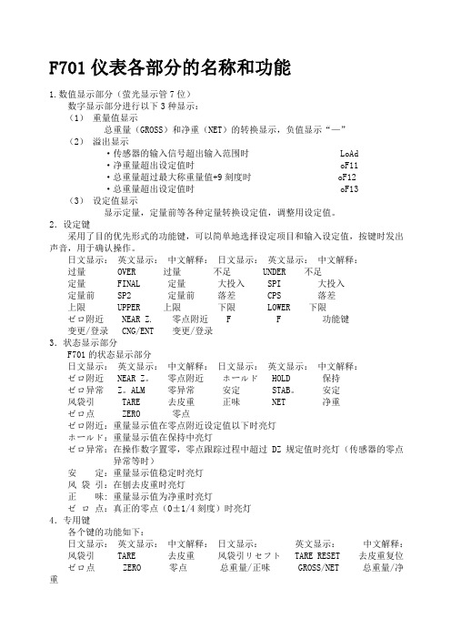
F701仪表各部分的名称和功能1.数值显示部分(萤光显示管7位)数字显示部分进行以下3种显示:(1)重量值显示总重量(GROSS)和净重(NET)的转换显示,负值显示“—”(2)溢出显示·传感器的输入信号超出输入范围时 LoAd·净重量超出设定值时 oF11·总重量超过最大称重量值+9刻度时 oF12·总重量超出设定值时 oF13 (3)设定值显示显示定量,定量前等各种定量转换设定值,调整用设定值。
2.设定键采用了目的优先形式的功能键,可以简单地选择设定项目和输入设定值,按键时发出声音,用于确认操作。
日文显示:英文显示:中文解释:日文显示:英文显示:中文解释:过量 OVER 过量不足 UNDER 不足定量 FINAL 定量大投入 SPI 大投入定量前 SP2 定量前落差 CPS 落差上限 UPPER 上限下限 LOWER 下限ゼロ附近 NEAR Z. 零点附近 F F 功能键变更/登录 CNG/ENT 变更/登录3.状态显示部分F701的状态显示部分日文显示:英文显示:中文解释:日文显示:英文显示:中文解释:ゼロ附近 NEAR Z。
零点附近ホールド HOLD 保持ゼロ异常 Z。
ALM 零异常安定 STAB。
安定风袋引 TARE 去皮重正味 NET 净重ゼロ点 ZERO 零点ゼロ附近:重量显示值在零点附近设定值以下时亮灯ホールド:重量显示值在保持中亮灯ゼロ异常:在操作数字置零,零点跟踪过程中超过DZ规定值时亮灯(传感器的零点异常等时)安定:重量显示值稳定时亮灯风袋引:在刨去皮重时亮灯正味: 重量显示值为净重时亮灯ゼロ点:真正的零点(0±1/4刻度)时亮灯4.专用键各个键的功能如下:日文显示:英文显示:中文解释:日文显示:英文显示:中文解释:风袋引 TARE 去皮重风袋引リセフト TARE RESET 去皮重复位ゼロ点 ZERO 零点总重量/正味 GROSS/NET 总重量/净重风袋引:刨去皮重(风袋引▽亮灯)风袋引リセフト:去皮重复位(风袋引▽灯灭)但是不解除容器自重的设定ゼロ:→登录将总重量值置为零,但是当重量值超过DZ规定值时,按此键零异常▽灯亮总重量/净重:进行重量显示值的转换(总重量/净重)。
欧姆龙 MQS5021C 温度和过程输入图形显示面板仪表和数据记录器用户指南说明书

年保修5线形图制图模式主屏幕 -反相模式水平条形图模式快速入门电子邮件: *************.com 索取最新的产品手册: 访问 ®进行网购用户指南如需阅读完整产品手册,请访问:/manuals/manualpdf/M5021.pdfDPi1701 配有无线选件的 温度和过程输入 图形显示面板仪表和数据记录器图1. 配有USB 和无线选件的DPi1701背面板视图图2. 电源和机械继电器输出连接图3. 不同的输入类型连接功率L (+)N (-)输出1N ON CC输出21(-)输入2(+)34512345678910678910–++–V+–I–EXC+OUT R S 2 3 2GND RX TX N ON CC+–天线USB 端口输入1(-)2(+)345678910热电偶连接1(-)输入2345678910RTD (100 Ω)连接3线2线1(-)输入23(+)45678910过程(伏特)连接+–V 1(-)输入234(+)5678910过程(电流)连接+–0/20mA 4/20mAI–+2-1图4. RS232连接 图5. 激励电压和模拟输出连接图6. 配置菜单流程图1输入2345678910RS232连接GND RXTX 激励和模拟输出不可用RS2322-2图8. 最小值/最大值流程图图9. 锁定/解锁流程图3-13-2规格摘要一般热电偶精度J 型、K 型、E 型和T 型: 0.5ºC (0.9ºF) R 型和S 型: 2.5°C (4.5°F)或满量程的0.5%热电偶范围J 型: -100 ~ 760ºC (-148 ~ 1400ºF) K 型: -100 ~ 1260ºC (-148 ~ 2300ºF) E 型: -200 ~ 849°C (-328 ~ 1560°F) T 型: -200 ~ 400ºC (-328 ~ 752ºF) R&S 型: 100 ~ 1760ºC (212 ~ 3200ºF)热电偶预热时间: 45分钟热电偶零点漂移: 0.06°C/°C 热电偶开路检测: 量程向上热电偶导线电阻: 最大100 ΩRTD : 100 Ω铂丝,2线或3线制,0.00385曲线RTD 精度: 0.5ºC (0.9ºF)RTD 范围: -200 ~ 850ºC (-328 ~ 1562ºF)RTD 开路检测: 放大比例过程(电压或电流) 输入精度: 读数的0.1%电压输入范围: 0 ~ 10 Vdc 电流输入范围: 0 ~ 20 mA 和4 ~ 20 mA 采样率: 每秒4个样本常规电源: 90/240 Vac +/-10%,50-400 Hz 工作条件: 0 ~ 50ºC (32 ~ 122ºF),90%相对湿度,无冷凝防护等级: NEMA -1/Type 1等级前盖外形尺寸: 48(高)x 96(宽)x 118mm (深)(1.89 x 3.78 x 4.65")面板开孔: 45(高)x 92mm (宽)(1.772 x 3.622")重量: 295 g (0.65 lbs)MQS5021/0613保修/免责声明OMEGA ENGINEERING, INC.保证本设备自购买之日起13个月内不存在材料和工艺缺陷。
DSO5000系列数字存储示波器用户手册(Ver0.9)
IT5600 5800手持线式条码扫描器用户手册说明书
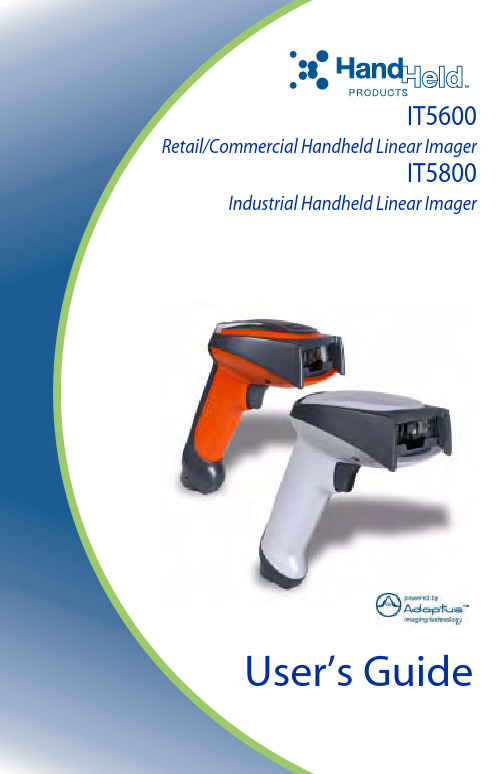
™ IT5600Retail/Commercial Handheld Linear ImagerIT5800 Industrial Handheld Linear ImagerUser’s GuideiChapter 1 - Getting StartedIT5600/5800.........................................................................1-1About This Manual...............................................................1-1Unpacking the Scanner.........................................................1-1IT5600 Models .....................................................................1-2IT5800 Models......................................................................1-2IT5600/5800 Scanner Identification.....................................1-3IT5800 Scanner (with aimer beam option) Identification....1-4Connecting the Scanner When Powered by Host(Keyboard Wedge) ............................................................1-5Reading Techniques .............................................................1-6Resetting the Standard Product Defaults..............................1-6Plug and Play........................................................................1-6Keyboard Wedge Connection...............................................1-7Laptop Direct Connect...................................................1-7RS-232............................................................................1-7Wand Emulation Plug & Play........................................1-8IBM 4683 Ports 5B, 9B, and 17 Interface......................1-8Connecting the Scanner with USB ....................................1-10IBM SurePos................................................................1-10USB PC or Macintosh Keyboard.................................1-11USB HID......................................................................1-11USB Com Port Emulation............................................1-12Connecting the Scanner with Serial Wedge.......................1-12Chapter 2 - Terminal InterfacesTerminal ID..........................................................................2-1Supported Terminals.............................................................2-2Keyboard Country................................................................2-4Keyboard Style.....................................................................2-5Keyboard Modifiers..............................................................2-6Table of ContentsConnecting the Scanner with RS-232 Serial Port ................2-8 RS-232 Baud Rate..........................................................2-9RS-232 Word Length: Data Bits, Stop Bits, and Parity2-10RS-232 Handshaking...................................................2-11Wand Emulation Connection.......................................2-11Wand Emulation Transmission Rate............................2-12Wand Emulation Polarity.............................................2-12Wand Emulation Idle...................................................2-13 Wand Emulation.................................................................2-13 Data Block Size............................................................2-13Delay Between Blocks.................................................2-14Overall Checksum........................................................2-14 Chapter 3 - OutputGood Read Indicators...........................................................3-1 Beeper – Good Read......................................................3-1Beeper Volume – Good Read........................................3-1Beeper Pitch – Good Read.............................................3-1Beeper Duration – Good Read.......................................3-2LED – Good Read..........................................................3-2Number of Beeps – Good Read.....................................3-2 Good Read Delay..................................................................3-3 User-Specified Good Read Delay..................................3-3 Trigger Modes......................................................................3-3 Manual/Serial Trigger....................................................3-3Automatic Trigger..........................................................3-4Presentation Mode..........................................................3-5 Hands Free Time-Out...........................................................3-5Reread Delay........................................................................3-5 User-Specified Reread Delay.........................................3-6 Aimer Beam Delay (Aimer Beam option only)....................3-7 User-Specified Aimer Beam Delay................................3-7 Aimer Mode (Aimer Beam option only)..............................3-7Aimer Beam Time-Out (Aimer Beam option only).............3-8Centering Window................................................................3-8 iiOutput Sequence Overview................................................3-10 Output Sequence Editor................................................3-11Require Output Sequence.............................................3-11 Multiple Symbols................................................................3-13No Read..............................................................................3-13Video Reverse.....................................................................3-14 Chapter 4 - Data EditingPrefix/Suffix Overview.........................................................4-1 To Add a Prefix or Suffix: 2To Clear One or All Prefixes or Suffixes:......................4-3To Add a Carriage Return Suffix to all Symbologies....4-3Prefix Selections.............................................................4-3Suffix Selections.............................................................4-4Function Code Transmit.................................................4-4 Intercharacter, Interfunction, and Intermessage Delays.......4-4 Intercharacter Delay.......................................................4-5User Specified Intercharacter Delay...............................4-5Interfunction Delay.........................................................4-6Intermessage Delay........................................................4-6 Chapter 5 - Data FormattingData Format Editor Introduction...........................................5-1 To Add a Data Format....................................................5-1Other Programming Selections......................................5-2Data Format Editor Commands......................................5-2Data Format Editor.........................................................5-4Data Formatter................................................................5-5Alternate Data Formats..................................................5-5 Chapter 6 - Secondary InterfaceIT5600 Models......................................................................6-1IT5800 Models......................................................................6-1Enabling the Secondary Interface.........................................6-1Secondary RS-232 Connection.............................................6-2iiiSecondary Code 39 Wand Emulation...................................6-2Secondary Laser Emulation..................................................6-3Laser Emulation Transmission Rate.....................................6-3Laser Emulation Polarity......................................................6-4Laser Emulation Idle.............................................................6-4Secondary Trigger Mode......................................................6-4Hands Free Time-Out...........................................................6-5 Chapter 7 - SymbologiesIntroduction...........................................................................7-1All Symbologies...................................................................7-1Message Length....................................................................7-2Codabar.................................................................................7-3 Codabar Start/Stop Characters......................................7-3Codabar Check Character..............................................7-3Codabar Concatenation..................................................7-4Codabar Message Length...............................................7-5 Code 39.................................................................................7-5 Code 39 Start/Stop Characters.......................................7-5Code 39 Check Character...............................................7-6Code 39 Message Length...............................................7-6Code 39 Append.............................................................7-7Code 32 Pharmaceutical (PARAF)................................7-7Full ASCII......................................................................7-8Code 39 Code Page........................................................7-9 Interleaved 2 of 5..................................................................7-9 Check Digit....................................................................7-9Interleaved 2 of 5 Message Length..............................7-10 Code 93...............................................................................7-11 Code 93 Message Length.............................................7-11Code 93 Code Page......................................................7-11 Code 2 of 5..........................................................................7-12 Code 2 of 5 Message Length........................................7-12IATA Code 2 of 5 Message Length.............................7-13 Matrix 2 of 5.......................................................................7-13 Matrix 2 of 5 Message Length.....................................7-14 ivCheck Digits Required.................................................7-14 Code 11 Message Length.............................................7-15 Code 128.............................................................................7-15 ISBT 128 Concatenation..............................................7-16 Code 128 Message Length...........................................7-16 Code 128 Code Page....................................................7-16 Code 128 Function Code Transmit..............................7-17 Telepen................................................................................7-17 Telepen Output.............................................................7-17 Telepen Message Length..............................................7-18 UPC A.................................................................................7-18 UPC A Check Digit......................................................7-18 UPC A Number System...............................................7-18 UPC A Addenda...........................................................7-20 UPC A Addenda Required...........................................7-20 UPC A Addenda Separator...........................................7-20 UPC-A/EAN-13 with Extended Coupon Code...................7-21 UPC E0 and UPC E1..........................................................7-21 UPC E0 and UPC E1 Expand.......................................7-22 UPC E0 and UPC E1 Addenda Required.....................7-22 UPC E0 and UPC E1 Addenda Separator....................7-22 UPC E0 Check Digit....................................................7-23 UPC E0 Number System..............................................7-23 UPC E0 Addenda.........................................................7-23 EAN/JAN 13.......................................................................7-24 EAN/JAN 13 Check Digit............................................7-24 EAN/JAN 13 Addenda.................................................7-24 EAN/JAN 13 Addenda Required.................................7-25 EAN/JAN 13 Addenda Separator.................................7-25 ISBN Translate.............................................................7-25 EAN/JAN 8.........................................................................7-26 EAN/JAN 8 Check Digit..............................................7-26 EAN/JAN 8 Addenda...................................................7-26 EAN/JAN 8 Addenda Required...................................7-27 EAN/JAN 8 Addenda Separator...................................7-27vMSI Check Character...................................................7-28MSI Message Length...................................................7-28 Plessey Code.......................................................................7-29 Plessey Message Length..............................................7-29 RSS Limited.......................................................................7-30RSS Expanded....................................................................7-31 RSS Expanded Message Length..................................7-31 EAN•UCC Emulation.........................................................7-31China Post Code.................................................................7-32Korea Post Code.................................................................7-33 Korea Post Message Length.........................................7-33 PosiCode A and B...............................................................7-34 PosiCode Message Length...........................................7-34 Codablock F........................................................................7-35 Codablock F Message Length......................................7-35 Code 16K............................................................................7-36 Code 16K Message Length..........................................7-36 Code 49...............................................................................7-37 Code 49 Message Length.............................................7-37 Chapter 8 - Interface KeysKeyboard Function Relationships.........................................8-1Supported Interface Keys ....................................................8-3 Chapter 9 - UtilitiesTo Add a Test Code I.D. Prefix to All Symbologies............9-1Show Software Revision.......................................................9-1Show Data Format................................................................9-1Resetting the Standard Product Defaults..............................9-1Temporary Visual Menu 2003 Configuration......................9-2 Chapter 10 - Visual Menu 2003Visual Menu 2003 Introduction..........................................10-1 Installing Visual Menu 2003 from the Web.................10-1 viChapter 11 - Serial Programming CommandsConventions........................................................................11-1Menu Command Syntax.....................................................11-1 Query Commands.........................................................11-2Concatenation of Multiple Commands.........................11-2Responses.....................................................................11-2Examples of Query Commands....................................11-3 Trigger Commands.............................................................11-4Resetting the Standard Product Defaults............................11-4Menu Commands................................................................11-5 Chapter 12 - Product SpecificationsIT5600 Product Specifications............................................12-1IT5600 Depth of Field........................................................12-2IT5800 Product Specifications ...........................................12-3IT5800 Depth of Field........................................................12-4Standard Cable Pinouts.......................................................12-5 Chapter 13 - MaintenanceRepairs................................................................................13-1Maintenance........................................................................13-1 Cleaning the Scanner’s Window..................................13-1Inspecting Cords and Connectors.................................13-1Replacing the Interface Cable......................................13-2 Troubleshooting..................................................................13-3 Chapter 14 - Customer SupportProduct Service and Repair.................................................14-1 Online Product Service and Repair Assistance............14-2 Technical Assistance...........................................................14-2 Online Technical Assistance........................................14-2 Limited Warranty................................................................14-2viiAppendix A - Appendix ASymbology Chart..................................................................A-1ASCII Conversion Chart (Code Page 1252).........................A-2Code Page Mapping of Printed Bar Codes...........................A-4 viiiThis is a “Table of Contents preview” for quality assuranceThe full manual can be found at /estore/catalog/ We also offer free downloads, a free keyboard layout designer, cable diagrams, free help andsupport. : the biggest supplier of cash register and scale manuals on the net。
昌辉双回路数字光柱显示控制仪.
目录一、技术参数 (1)二、仪表外型开孔尺寸 (2)三、接线说明 (2)四、功能操作 (5)(一)仪表面板 (5)(二)仪表上电 (6)(三)仪表一级参数设定 (7)(四)仪表二级参数设定 (8)(五)仪表参数说明 (10)(六)参数设定方式 (11)(七)分度号设置 (11)五、型谱表 (12)一、主要技术参数输入信号电偶:B、S、K、E、J、T、WRe3-25等电阻:Pt100、Cu100、Cu50、BA1、BA2等或远传压力电阻电流:0~10mA、4~20mA、0~20mA、0~10mA开方、4~20mA开方等──输入阻抗≤250Ω电压:0~5V、1~5V、0~5V开方、1~5V开方──输入阻抗≥250KΩ测量范围-1999~9999字测量精度0.5%FS±1字或0.2%FS±1字分辨率1、0.1、0.01或0.001字显示方式-1999~9999测量值显示-1999~9999设定值显示0~100%测量值光柱显示发光二极管工作状态显示光柱精度光柱显示精度为1%输出信号DC0~10mA(负载电阻≤750Ω)DC4~20mA(负载电阻≤500Ω)DC0~5V (负载电阻≥250KΩ)DC1~5V (负载电阻≥250KΩ)报警输出继电器控制输出──继电器ON/OFF带回差。
触点容量:AC220V/1A;DC24/3A(阻性负载)报警精度±1字通讯输出接口方式─标准串行双向通信接口:光电隔离RS-485,RS-232等波特率─1200~9600bps内部自由设定,采用标准MODBUS RTU通讯协议馈电输出DC24V,负载电流≤30mA温度补偿0~50℃数字式温度自动补偿参数设定面板轻触式按键数字设定参数设定值断电后永久保存参数设定值密码锁定保护方式输入回路断线报警,继电器输出状态LED指示输入超/欠量程报警电源欠压自动复位工作异常自动复位(Watch Dog)联机通讯通讯为二线制、三线制(如RS-485、RS-232等),亦可由用户特殊要求,波特率1200~9600bps 可由仪表内部参数自由设定。
F701仪表使用说明
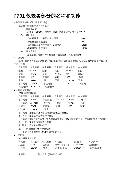
F701仪表各部分的名称和功能1.数值显示部分(萤光显示管7位)数字显示部分进行以下3种显示:(1)重量值显示总重量(GROSS)和净重(NET)的转换显示,负值显示“—”(2)溢出显示·传感器的输入信号超出输入围时LoAd·净重量超出设定值时oF11·总重量超过最大称重量值+9刻度时oF12·总重量超出设定值时oF13(3)设定值显示显示定量,定量前等各种定量转换设定值,调整用设定值。
2.设定键采用了目的优先形式的功能键,可以简单地选择设定项目和输入设定值,按键时发出声音,用于确认操作。
日文显示:英文显示:中文解释:日文显示:英文显示:中文解释:过量OVER 过量不足UNDER 不足定量FINAL 定量大投入SPI 大投入定量前SP2 定量前落差CPS 落差上限UPPER 上限下限LOWER 下限ゼロ附近NEAR Z. 零点附近 F F 功能键变更/登录CNG/ENT 变更/登录3.状态显示部分F701的状态显示部分日文显示:英文显示:中文解释:日文显示:英文显示:中文解释:ゼロ附近NEAR Z。
零点附近ホールドHOLD 保持ゼロ异常Z。
ALM 零异常安定STAB。
安定风袋引TARE 去皮重正味NET 净重ゼロ点ZERO 零点ゼロ附近:重量显示值在零点附近设定值以下时亮灯ホールド:重量显示值在保持中亮灯ゼロ异常:在操作数字置零,零点跟踪过程中超过DZ规定值时亮灯(传感器的零点异常等时)安定:重量显示值稳定时亮灯风袋引:在刨去皮重时亮灯正味: 重量显示值为净重时亮灯ゼロ点:真正的零点(0±1/4刻度)时亮灯4.专用键各个键的功能如下:日文显示:英文显示:中文解释:日文显示:英文显示:中文解释:风袋引TARE 去皮重风袋引リセフトTARE RESET 去皮重复位ゼロ点ZERO 零点总重量/正味GROSS/NET 总重量/净重风袋引:刨去皮重(风袋引▽亮灯)风袋引リセフト:去皮重复位(风袋引▽灯灭)但是不解除容器自重的设定ゼロ:→登录将总重量值置为零,但是当重量值超过DZ规定值时,按此键零异常▽灯亮总重量/净重:进行重量显示值的转换(总重量/净重)。
DPtech LSW5600系列以太网交换机安装手册v1.5
DPtech LSW5600 系列以太网交换机安装手册
2.2.4 抗干扰要求 ..................................................................................................................... 2-3 2.2.5 防雷击要求 ..................................................................................................................... 2-3 2.2.6 接地要求 ......................................................................................................................... 2-3 2.2.7 布线要求 ......................................................................................................................... 2-3 2.3 激光使用安全 .................................................................................................................... 2-3 2.4 安装工具 ............................................................................................................................ 2-4
光测试仪表说明书
WARNING安全规则:为防止对仪表造成损坏,请勿在高温、高压、潮湿等超过产品规定环境下使用,不得私自拆机进行维修,请按照本手册要求正常使用。
认证与品质保证:我们保证产品于工厂交付使用时,符合本手册所标称的各项技术指标通告:本手册的内容如有修改,恕不另行通知保修须知保修期:自购买之日起12个月内(人为原因造成的损坏不予保修)1手持式光功率计用户手册产品规格型号A测试范围:-70~+10dBm,B测试范围:-50~+26dBm特性介绍●高精度测量和显示:可提供0.01dB的显示精度。
●快速反应和测量:可快速跟踪和实时测量显示光功率。
●宽测量量程:可提供80dB的光功率测量量程。
●6个基本波长校准点:850nm、1300nm、1310nm、1490nm、1550nm、1625nm,其他波长可根据用户要求增加或减少。
●支持光功率的绝对测量和相对测量。
●实时监测和显示电池电量,在电池电量过低时进行告警。
●液晶屏背光显示功能。
●可自由设置电源自动关机功能。
●支持客户自校准功能,便于客户计量和使用●采用通用AAA(7号)电池设计,客户维护方便1.2装箱清单1)光功率计………………………… 1台2)软包………………………… 1个3)使用说明书………………………… 1本4)AAA电池…………………………… 3个(运输许可时)5)产品合格证…………………………… 1份1.33产品外观及功能键介绍1.3.11)ON/OFF键:点按3秒钟,即可实现关机功能。
/取消功能,同时电源符号显示在显示屏下部。
电源符号显示时表示自动关机使能,可实现10分钟自动关机。
仪表开机默认电源自动关机功能,若需要长时间使用,可短按该ON/OFF。
2)dBm/w键:重复按动可选择不同的单位显示光功率的测量值为单位和以dBm为单位显示检测到的光功率大小)。
3)λ键:波长选择键,按动λ键,可以选择不同的校准波长,如850nm、1300nm、1310nm、1490nm、1550nm、1625nm六种校准波长供选择,该值也将在LCD上显示。
波伦夫(Balluff)条件监测传感器BCM R15E-002-DI00-01,5-S4 产品说明说

1) Membrane 2) LED orange 3) LED green4) Cable lengthBasic featuresApproval/ConformityCE cULus WEEEFunction Vibration Velocity Vibration Acceleration Vibration Severity Zone Contact Temperature Relative Humidity Ambient Pressure Sensor Self-AwarenessPrinciple of operation Condition Monitoring Sensors SeriesR15Display/OperationDisplayRun - LED greenCommunication - LED green, slow flashing (1 Hz)Ping - LED green, asyncronous very fast flashing (4 Hz) and fast flashing (2 Hz)Event - LED orange, fast flashing (2 Hz)Electrical connectionBending radius min., fixed cable 3 x D Bending radius min., flexible cable 5 x DCable diameter D 2.9 mm +0.1/-0.05 mm Conductor cross-section 0.14 mm²ConnectionCable with connector, M12x1-Male, 3-pin, 1.5 m, PUR Number of conductors 3Polarity reversal protected yes Protection against device mix-ups yes Short-circuit protectionyesElectrical dataCurrent draw max.10 mA Operating voltage Ub 18...30 VDC Protection classIII Rated operating voltage Ue DC 24 V Ready delay tv max.1.5 sEnvironmental conditionsAmbient temperature0...70 °CEN 61000-4-2, ESD Severity Level 2 EN 61000-4-3, RFI Severity Level 3 EN 61000-4-4, Burst Severity Level 4 EN 61000-4-6, High-frequency fields Severity Level 3 IP rating IP67Storage temperature-20...70 °CFunction module ambient pressure Ambient pressure, measuring range300…1100 hPa Ambient pressure, non-linearity±0.1 %FS Ambient pressure, resolution0.15 hPaFunction module contact temperature Contact temperature, measuring error±2 %FSContact temperature, measuringrange0…70 °CContact temperature, non-linearity±0.75 %FS Contact temperature, resolution0.1 °CContact temperature, settling time 5 min Function module relative humidity Relative humidity, measuring range5…95 %rF Relative humidity, non-linearity±2.5 %FS Relative humidity, resolution 1 %rFRelative humidity, settling time 5 min Function module vibrationVibration, frequency range 2...3200 Hz Vibration, measuring principle MEMS Vibration, number of measuring axes3Vibration, sampling rate6400 Hz Function module vibration accelerationVibration acceleration, measuringerror RMS±5%*********Vibration acceleration, measuringrange RMS0…16 gVibration acceleration, non-linearityRMS±2%*********Vibration acceleration, resolutionRMS*************Vibration acceleration, statistical evaluation variables [for each measuring axis]RMSPeak to PeakFunction module vibration velocityVibration velocity, evaluationvariables [for each measuring axis]RMSPeak to PeakMeanStandard DeviationCrest FactorSkewnessKurtoisisVibration velocity, measuring errorRMS±5%*********Vibration velocity, measuring rangeRMS0…220mm/********Vibration velocity, non-linearity RMS±2%*********Vibration velocity, resolution RMS0.42mm/********MaterialHousing material Stainless steel (1.4404),Membrane: ePTFE with nylonfleeceMechanical dataDimension20 x 10 x 32 mmMounting Screw M3 (2x)Weight30 gOutput/InterfaceBaud rate COM3 (230,4 kBaud)Interface IO-Link 1.1Interface setting option Flexible process dataconfigurationVibration measurement based onISO 10816-3Data preprocessing (statistics)Events (pre-alarms and mainalarms)Delay times for alarmsSearch function with LED display(ping)Process data IN20 bytesProcess data OUT0 bytesProcess data cycle min.10 msRemarksFor additional information, refer to user's guide. Order accessories separately.For more information about MTTF and B10d see MTTF / B10d CertificateIndication of the MTTF- / B10d value does not represent a binding composition and/or life expectancy assurance; these are simply experiential values with no warranty implications. These declared values also do not extend the expiration period for defect claims or affect it in any way.Connector DrawingsWiring Diagrams。
虹润NHR-5200说明书
版本号:5200-160112NHR-5200系列双回路数字显示控制仪使用说明书一、产品介绍NHR-5200系列双回路数字显示控制仪采用了表面贴装工艺,全自动贴片机生产,具有很强的抗干扰能力。
本仪表支持多种信号类型输入,可与各类传感器、变送器配套使用,实现对温度、压力、液位、速度、力等物理的测量显示,带报警控制、模拟变送输出、485/232通讯等输出功能,带双屏数码管显示,可自由设定上、下窗口显示内容,可订制数学运算功能,可针对两路测量信号进行加、减、乘、除运算,其适用范围非常广泛。
二、技术参数 输入输入信号 电流 电压 电阻 电偶 输入阻抗 ≤250Ω ≥500K Ω 输入电流最大限制 ≤30mA 输入电压最大限制 ≤6V 输出输出信号 电流 电压继电器24V 配电或馈电 输出负载能力≤500Ω≥250K Ω(注:需要更高负载能力时须更换模块)AC220V/0.6(小) DC24V/0.6A (小) AC220V/3A (大) DC24V/3A (大) 见备注≤30mA综合参数 测量精度 0.2%FS ±1字设定方式 面板轻触式按键数字设定;参数设定值密码锁定;设定值断电永久保存。
显示方式 -1999~9999测量值显示,0~100%测量值光柱显示,发光二级管工作状态显示 使用环境 环境温度:0~50℃;相对湿度:≤85%RH ; 避免强腐蚀气体 工作电源 AC 100~240V (开关电源),(50-60HZ ); DC 20~29V (开关电源) 功耗 ≤5W 结构 标准卡入式通讯采用标准MODBUS 通讯协议,RS-485通讯距离可达1公里,RS-232通讯距离可达15米注:仪表带通讯功能时,通讯转换器最好选用有源转换器备注:外形尺寸为D 、E 的仪表继电器输出时允许负载能力为AC220V/0.6A ,DC24V/0.6A 三、仪表的显示面板和功能键1)仪表外形尺寸及开孔尺寸:外形尺寸开孔尺寸160*80mm(横式/光柱)152*76mm80*160mm(竖式/光柱)76*152mm96*96mm(方式)92*92mm96*48mm(横式)92*45mm48*96mm(竖式)45*92mm72*72mm(方式)68*68mm2)数码管PV:显示第一路测量值;可根据要求自行选择显示;在参数设定状态下,显示参数符号。
5200双回路数字显示控制仪使用说明书

一、概述5200系列双回路数字显示控制仪采用了表面贴装工艺,全自动贴片机生产,具有很强的抗干扰能力。
本仪表支持多种信号类型输入,可与各类传感器、变送器配套使用,实现对温度、压力、液位、速度、力等物理的测量显示,带报警控制、模拟变送输出、485/232通讯等输出功能,带双屏数码管显示,可自由设定上、下窗口显示内容,可订制数学运算功能,可针对两路测量信号进行加、减、乘、除运算,其适用范围非常广泛。
二、技术规格备注:外形尺寸为D、E的仪表继电器输出时允许负载能力为AC125V/0.6A,DC24V/0.6A三、仪表的面板及显示功能仪表的面板及显示功能2)显示窗PV显示窗:显示第一路测量值;可根据要求自行选择显示;在参数设定状态下,显示参数符号SV显示窗:显示第二路测量值;可根据要求自行选择显示;在参数设定状态下,显示设定参数值3)面板指示灯4) 操作按键1AL1:第一路第一报警指示灯确认键:数字和参数修改后的确认.1AL2:第一路第二报警指示灯翻页键:参数设置下翻键2AL1:第二路第一报警指示灯位移键:按一次数据向左移动一位2AL2:第二路第二报警指示灯返回键:长按2秒可返回上一级参数减少键:用于减少数值增加键:用于增加数值四、标准配线仪表在现场布线注意事项:PV 输入(过程输入)1. 减小电气干扰,低压直流信号和传感器输入的连线应远离强电走线。
如果做不到应采用屏蔽导线,并在一点接地。
2. 在传感器与端子之间接入的任何装置,都有可能由于电阻或漏流而影响测量精度。
热偶或高温计输入应采用与热偶对应的补偿导线作为延长线,最好有屏蔽RTD(铂电阻)输入三根导线的电阻必须相同,每根导线电阻不能超过15Ω五、通电设置仪表接通电源后,即进入自检状态,自检完毕后,仪表自动转入工作状态,在工作状态下,按压键显示LOC,LOC参数设置有如下:1、1)Loc等于任意参数可进入一级菜单(LOC=00;132时无禁锁);2) Loc=132,按压键4秒可进入二级菜单;3) Loc=130,按压键4秒可进入时间设置菜单;对于带打印功能的表.4) Loc 等于其他值,按压键4秒退出到测量画面。
GEM 5000型号仪表说明书

GEM 5000 MODELSModel Meter with AC Charger – No Kit5000CH 4, CO 2, 02, static and differential pressure 5000+Adds CO (0-2000 ppm), and H 2S (0-500 ppm) 5000+1Adds CO (0-2000 ppm), and H 2S (0-1000 ppm) 5000+5Adds CO (0-2000 ppm), and H 2S (0-5000 ppm) 5000+10Adds CO (0-2000 ppm), and H 2S (0-10000 ppm) 5000Nav Adds Built-in GPS5000Nav+Adds Built-in GPS, CO (0-2000 ppm), and H 2S (0-500 ppm) 5000Nav+1Adds Built-in GPS, CO (0-2000 ppm), and H 2S (0-1000 ppm) 5000Nav+5Adds Built-in GPS, CO (0-2000 ppm), and H 2S (0-5000 ppm) 5000Nav+10Adds Built-in GPS, CO (0-2000 ppm), and H 2S (0-10000 ppm) GM5K-KitGEM 5000 Kit Includes:Hoses, heavy duty water trap filter, soft case, electronic manual accompanies software, LANDTEC System GasAnalyzer Manager (LSGAM) software, USB download cable and hard-case.The GEM™ 5000 is designed specifically for use on landfills to monitor Landfill Gas (LFG) collection and control systems. The GEM™ 5000 samples and analyzes the methane, carbon dioxide and oxygen content of landfill gas with options for additional analysis.FEATURES•Measures % CH 4, CO 2 and O 2 Volume, static pressure and differential pressure•Calculates balance gas, flow (SCFM) and calorific value•High accuracy and fast response time •Lighter and more compact•Certified intrinsically safe for landfill use •Calibrated to ISO/IEC 17025•CO and H 2S (on Plus models only) •3 year warranty•Annual recommended factory service•Available with GPS and additional gas detectionBENIFITS•Designed specifically for use on landfills to monitor landfill gas (LFG) extraction systems, flares, and migra-tion control systems.•No need to take more than one instrument to site •Can be used for monitoring subsurface migration probes and for measuring gas composition, pressure and flow in gas extraction systems•The user is able to set up comments and questions to record information at site and at each sample point •Ensures consistent collection of data for better analysis •Streamlined user experience reduces operational timesAPPLICATIONS•Landfill Gas Collection & Control Systems •Environmental Compliance •Landfill Gas to Energy•Subsurface Migration ProbesCALL GEOTECH TODAY (800) 833-7958Geotech Environmental Equipment, Inc.2650 East 40th Avenue • Denver, Colorado 80205 (303) 320-4764 • FAX (303) 322-7242email:********************• website: landtec_gem_5000.qxp 11/19/19SPECIFICATIONSGas RangesGases Measured CH4By dual wavelength infrared cell with reference channelCO2By dual wavelength infrared cell with reference channelO2By internal electrochemical cellCO By internal electrochemical cellH2S By internal electrochemical cellRanges CH40-100% (vol)CO20-100% (vol)O20-25% (vol)CO0-2000 ppm***H2S0-500 ppm***Gas Accuracy*CH40-5% ±0.3% (vol)0-70% ±0.5% (vol)70-100% ±1.5% FSCO20-5% ±0.3% (vol)0-60% ±0.5% (vol)60-100% ±1.5% FSO20-25% ±1.0% (vol)CO (H2)**0-2000 ppm ±1.0% FSH2S0-500 ppm ±2.0% FS* Typical accuracy after calibration as recommended in the operations manual.** Hydrogen compensated Carbon Monoxide measurement.*** Additional ranges available, call for more information.Other ParametersUnit Resolution CommentsEnergy BTU/hr1000 BTU/hr Calculated from specific parameters Static Pressure in. H2O0.1 in. H2O Direct MeasurementDifferential Pressure in. H2O0.001 in. H2O Direct MeasurementImportant Note: The information in this document is correct at the time of generation.Specification may change without prior notice as a result of continuing development.PumpFlow Typically 550cc/min.Flow with 80 in. H2O vacuum Approximately 80cc/min.Environmental ConditionsOperating Temperature Range14°F–122°F (-10°C–50°C)Operating Pressure-100 in. H2O, +100 in. H2O (-250 mbar, +250 mbar)Relative Humidity0-95% non-condensingBarometric Pressure±14.7 in. Hg (±500 mbar) from calibration pressureBarometric Pressure Accuracy±1% typicallyPower SupplyBattery Life Typical use 8 hours from fully chargedCharge Time Approximately 4 hours from complete dischargeCertification RatingATEX II 2G Ex ib IIA T1 Gb (Ta= -10°C to +50°C)ISO17025ISO/IEC17025:2005 Accreditation #66916CSA Ex ib IIA T1 (Ta= -10°C to +50°C) (Canada), AEx ib IIA T1 (Ta= -10°C to +50°C) USACALL GEOTECH TODAY (800) 833-7958Geotech Environmental Equipment, Inc.2650 East 40th Avenue • Denver, Colorado 80205(303) 320-4764 • FAX (303) 322-7242email:********************•website: 。
G系列山猫滑移仪表板说明(标准型)

显示小时数.
左仪表板
铲斗水平位置开关 (选装件)
压下则接通铲斗水平定位功 能. •再次压下则断开.
•压下此开关并保持2秒针. •计时表会显示:
•控制电脑的软件版本号
•自动熄火状态 •正常熄火
•自动熄火
左仪表板
附件辅助液压装置
高流量
(只适用于装配有高流量泵的机器)
•压下则接通高流
量辅助液压回路.
•第二次压下则断 开高流量辅助液 压回路.
左仪表板
附件辅助液压装置
最大/可变流量开关
•压下此开关一次:接通可 变流量. (PWM 模式) •压下第二次:接通最大流 量.
•第三次压下则断开辅助 液压回路的供油.
左仪表板
附件辅助液压装置
辅助压力释放开关
• 按下并保持住
• 发动机将熄火.
• 辅助液压回路的压力会自动
卸压. • 取代旧车型启动钥匙
右标准仪表板
• 先导油压报警灯
• 指示灯亮且蜂鸣器报警,表 示: – 先导油压过低或系统异 常. – 可以读取故障代码. • 指示灯闪烁且蜂鸣器发出 不间断的报警声,表示 – 先导压力相当低. – 可以读取故障代码. – 机器将在15秒针内自动 熄火.
右标准仪表板
• 液压油温度报警灯
• 指示灯亮且蜂鸣器报警, 表示: – 液压油温度过高 – 可以读取故障代码. • 指示灯闪烁且蜂鸣器发 出不间断的报警声,表示 – 液压油温度相当高. – 机器将在15秒针内自 动熄火.
”左转动” 卸压的特征.
•卸压完成后,将启动钥匙转到 OFF位置.
左仪表板
山猫互锁控制系统(BICS)
压下此开关---操作机器
•压下此开关激活BICS 系统 (司机在驾驶室座椅座
gm仪表说明书
2.5串行口的连接------------------------------------------------------------------------------------------------------------7
6.操作--------------------------------------------------------------------------------------------------------------------------23
6.1仪表的工作状态------------------------------------------------------------------------------------------------23
3.1.13标定密码修改--------------------------------------------------------------------------------------------------14
3.2标定参数表----------------------------------------------------------------------------------------------------15
3.标定----------------------------------------------------------------------------------------------11
F701仪表使用说明
F701仪表各部分的名称和功能1.数值显示部分(萤光显示管7位)数字显示部分进行以下3种显示:(1)重量值显示总重量(GROSS)和净重(NET)的转换显示,负值显示“—”(2)溢出显示·传感器的输入信号超出输入范围时 LoAd·净重量超出设定值时 oF11·总重量超过最大称重量值+9刻度时 oF12·总重量超出设定值时 oF13(3)设定值显示显示定量,定量前等各种定量转换设定值,调整用设定值。
2.设定键采用了目的优先形式的功能键,可以简单地选择设定项目和输入设定值,按键时发出声音,用于确认操作。
日文显示:英文显示:中文解释:日文显示:英文显示:中文解释:过量 OVER 过量不足 UNDER 不足定量 FINAL 定量大投入 SPI 大投入定量前 SP2 定量前落差 CPS 落差上限 UPPER 上限下限 LOWER 下限ゼロ附近 NEAR Z. 零点附近 F F 功能键变更/登录 CNG/ENT 变更/登录3.状态显示部分F701的状态显示部分日文显示:英文显示:中文解释:日文显示:英文显示:中文解释:ゼロ附近 NEAR Z。
零点附近ホールド HOLD 保持ゼロ异常 Z。
ALM 零异常安定 STAB。
安定风袋引 TARE 去皮重正味 NET 净重ゼロ点 ZERO 零点ゼロ附近:重量显示值在零点附近设定值以下时亮灯ホールド:重量显示值在保持中亮灯ゼロ异常:在操作数字置零,零点跟踪过程中超过DZ规定值时亮灯(传感器的零点异常等时)安定:重量显示值稳定时亮灯风袋引:在刨去皮重时亮灯正味: 重量显示值为净重时亮灯ゼロ点:真正的零点(0±1/4刻度)时亮灯4.专用键各个键的功能如下:日文显示:英文显示:中文解释:日文显示:英文显示:中文解释:风袋引 TARE 去皮重风袋引リセフト TARE RESET 去皮重复位ゼロ点 ZERO 零点总重量/正味 GROSS/NET 总重量/净重风袋引:刨去皮重(风袋引▽亮灯)风袋引リセフト:去皮重复位(风袋引▽灯灭)但是不解除容器自重的设定ゼロ:→登录将总重量值置为零,但是当重量值超过DZ规定值时,按此键零异常▽灯亮总重量/净重:进行重量显示值的转换(总重量/净重)。
Vital Signs Monitor 52000 Series (VSM) 产品说明书
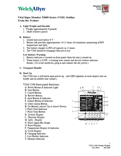
Vital Signs Monitor 52000 Series (VSM) OutlineTrain the TrainerA.Light Weight and Durable1. Weighs approximately 6 pounds2. Made of heavy plasticB.Battery1. Sealed lead acid battery 6 V2. Battery life provides approximately 10-12 hours of continuous monitoring of B/P,temperature and SpO2.3. The battery charges to 90% of capacity in 12 hours.4. The VSM should be charging when not in use.Low Battery Warning1. Battery indicator is located on front panel when the unit is turned on.2. When battery is LOW, a warning tone sounds and the low battery indicatorflashes. (To avoid shutdown, plug in and connect the AC power.)C.Transport HandleD.Start UpThe VSM runs a self-check upon power up. (All LED segments in each display turn on briefly and an audible tone sounds.)VSM 5200 front panel functions:A. Power Button & Indicator LightB. Start ButtonC. Cancel ButtonD. Review ButtonE. Auto Button & IndicatorF. Silence Button & IndicatorG. Select Alarm ButtonH. Set Buttons (Arrow Up or Arrow Down)I. Pulse Tone IndicatorJ. Pulse Tone ButtonK. Systolic DisplayL. Diastolic DisplayM. SpO2 DisplayN. Pulse Signal Bar GraphO. Pulse DisplayP. Temperature Display & IndicatorQ. Cycle DisplayR. Charging IndicatorS. Low Battery IndicatorT. Memory IndicatorF. Intended UseThe Welch Allyn VSM 5200 is intended to be used on adult and pediatric patients.•Adult: 12 years and over•Pediatric: 29 days to 12 years**NOTE** The Welch Allyn VSM 5200 is not designed to be used on NeonatalPatients.G. Limits1. This feature allows you to make changes to the high and low alarm limits for thefollowing vital signs.a. Systolic HIGH and Systolic LOWb. Diastolic HIGH and Diastolic LOWc. Pulse Rate HIGH and Pulse Rate LOWd. SpO2 LOW2. To make changes to the limits:a. Press Select Alarm buttonb. For the selected vital:Press Set Buttons, Up/Down Arrows, as needed to change the limit or (---) todisable the alarm.c. The alarm parameter you are changing, such as HR HIGH, will be displayed inthe appropriate display.d. Press Select Alarm Button to accept alarm limit and advance to next vital sign.e. To return to normal operation, do nothing for 10 seconds.3. Silence Button and IndicatorWhen an alarm sounds, pressing the Silence button will silence it for 30 seconds.You will see a flashing display to indicate the alarming parameter.H. NIBP1. Before starting the NIBP measurement, always perform the steps described below:a. Select appropriate cuff. The cuff is the appropriate size when the artery indexmarker lies somewhere between the range markings on the NIBP cuff.b. Position the cuff. The cuff should always be positioned on a bare arm, midwaybetween the shoulder and the elbow, with the artery index marker over thebrachial artery. It should fit comfortably to allow no more than 1-2 fingers spacebetween the cuff and the arm. During the NIBP measurement cycle, the patient should have no movement to the extremity and should remain quiet.NOTE: If the cuff is not level with the heart, there is a 1.8 mmHg drop to the systolic and diastolic pressures for every inch the arm is raised above theheart. For every inch the arm is lowered below the heart there is a 1.8mmHg rise in the systolic and diastolic pressures.2. Manual NIBP measurementsa. Attach the appropriate cuff to the patient’s arm.b. Press Start buttonc. When the B/P cycle is completed, a tone sounds and the NIBP results aredisplayed in the SYSTOLIC, DIASTOLIC and PULSE rate displays.d. The results are displayed for 2 minutes or until another NIBP cycleis initiated.NOTE: If the SpO2 sensor is attached and generating valid pulse data, thedisplayed PULSE rate is derived from the SpO2 sensor reading.3. Automatic NIBP—Interval measurementsa. Attach the appropriate cuff to the patient’s arm.b. Press Auto button to set the measurement interval which includes: ST (Stat), 1, 3, 4, 5, 10, 15, 30, 45, 60 and 90 minutes. The three dashes (---) in the displayindicate that the automatic mode for NIBP is turned OFF.c.Within ten seconds after you select an interval and assuming that safe venousreturn pressure has been maintained for at least 30 seconds, the monitorautomatically starts the first automatic NIBP cycle.d. When the cycle ends, a tone sounds and the monitor displays the reading. Themeasurement will remain on the screen until the next measurement cycle begins,2 minutes pass, or the Start button is pressed again.4. ST/ STAT MeasurementIf the selected interval is STAT, the monitor takes repeated NIBP measurementsfor up to 15 minutes, starting a new cycle each time the cuff deflates below10 mmHg.I. SpO2 Monitoring (if applicable)1. Verify that the SpO2 sensor is connected to the monitor.2. Attach the SpO2 sensor to the patient’s index finger. Do not attach the SpO2 sensorto the same limb as B/P cuff.3. Within a few seconds, the pulse signal bar graph reflects the strength and quality ofthe pulse.4. Within approximately 10 seconds, the initial measurement is displayed and a numericpulse rate value appears in the PULSE display.5. SpO2/Pulse Tone Volumea. Press Pulse Tone button to control volume of SpO2 pulse tone.b. The pulse tone can be adjusted to any of 5 volume settings from silent tohigh.c. To set the displayed new values, do nothing for 3 seconds.NOTE: Changing the volume of the pulse tone has no effect on the volume ofalarm tones.J. Temperature Monitoring (if applicable)If configured with the temperature option, the monitor can obtain predictive ormonitored temperature measurements.NOTE: Temperature range (Low--80'F and High--110'F)Predictive measurements: a one-time temperature reading which takes only afew seconds. Results are obtained in:Oral: approximately 4 secondsAxillary (ages less than 4 years): approximately 10 secondsRectal: approximately 15 secondsReadings will be displayed as: F Fahrenheit or C Celsius.Monitored measurements: continuous temperature monitoring used when thesituation prevents an accurate predictive measurement.Results are obtained in:Oral: 3 minutesAxillary: 5 minutesRectal: 3 minutesReadings will be displayed as: FM Fahrenheit Monitored or CM Celsius Monitored1. Prep Thermometer ProbeNOTE: Tip of Probe is preheated to 93'Fa. Hold the probe collar with the blue ejection button with your thumb and forefingerand withdraw the probe from the probe holder.b. Wait for the “OrL” to appear in the temperature display.c. Insert the probe into a new probe cover and press down firmly until a new probecover engages onto the probe.2. Taking Oral TemperaturesIt is IMPORTANT while taking an Oral predictive temperature to:a. Instruct the patient not to talk or move during the temperature reading process.b. Place the probe deep into the patient’s posterior sublingual pocket.c. Have the nurse hold the probe in place maintaining tissue contact until thetemperature is complete.d.The predictive temperature reading will be displayed for 1 minute in thetemperature display.e. Interferences with oral measurements for up to 20 minutes include:1. Ingesting hot or cold liquids2. Talking3. Eating food4. Chewing gum or mints5. Brushing teeth6. Mouth care7. Smoking8. Performing strenuous exercises3. Taking Axillary Temperaturesa. Hold the probe collar with your thumb and forefinger and withdraw the probefrom the probe holder.b. Wait for the “OrL” to appear in the temperature display.c. Press the Set-Arrow Up button once to change the display to “ALY”.d. Insert the probe into a new probe cover and press down firmly until a newprobe cover engages onto the probe.e. Lift the patient’s arm to fully expose the axilla. Place the probe tip as high aspossible in the axilla, aligning the probe vertically with the spine. Next, lowerthe patient’s arm down to make maximum contact with the probe tip. Thepatient should always remain still, maintaining good tissue contact throughoutthe process.f. The predictive temperature reading will be displayed for 1 minute in thetemperature display.NOTE: Quick predictive axillary temperature readings are accurate only for children under the age of four years old. If an axillary reading is desiredfor a patient age four and older, the Blue probe must be used in Monitor Mode.4. Taking Rectal TemperaturesFor rectal temperatures, use only the RECTAL PROBE with the RED ejectionbutton.a. Hold the probe collar with your thumb and forefinger and withdraw the probefrom the probe holder.b. Wait for the “REC” to appear in the temperature display.c. Load the probe cover onto the probe.d. Apply a thin coat of water-based lubricant to the tip of the probe cover(optional).e. Insert the probe tip 5/8 inch inside the rectal sphincter for adults andapproximately ½ inch for children.f. Tilt the probe slightly to ensure good tissue contact.g. The predictive temperature reading will be displayed for 1 minute in thetemperature display**WARNING** Use extreme care to avoid risk of bowel perforation.**NEVER** Reuse probe covers; reusing covers will give inaccurate temperaturereadings.5. Taking Monitor Mode Temperaturesa. Continuous monitoring mode is not recommended for use over 5 minutes.b. Measurements are not stored in memory.c. 3-5 minute thermometer reading is equivalent to using a glass thermometer.d. Useful for double-checking fast predictive readings; i.e. an infant exposed to coolambient temperatures or hypothermic patient.e. To use Monitor Mode:1. Select the correct probe and remove from probe holder.2. Load probe cover and wait one minute; the Monitor will automatically switchto Monitor Mode.3. Determine the site for the Temperature reading: Oral, Axillary, or Rectal4. Take the patient’s reading in appropriate site. Continue to hold the probe inposition for the required duration:Oral 3 minutesAxillary 5 minutesRectal 3 minutes5. Record the temperature before removing the probe from the site. MonitorMode temperatures are not stored in memory.6. Discard the probe cover. Upon returning the probe to the holder, thethermometer will revert back to default mode. Change as needed.NOTE: The thermometer enters Monitor Mode automatically if the probe is removed from the holder and not used for 60 seconds or if the patient’stemperature is too low to allow the device to predict a reading.K. Review Button1. Press Review button to display most recent set of vital signs.2. The Monitor stores 99 sets of data.3. The data will appear in appropriate displays and the Cycle display will show totalnumber of data sets currently in memory.L. Erasing Data1. All patient vital sign data is erased when the Monitor is powered Off.a. To erase patient data during normal operation, press and hold the Cancel buttonfor 3 seconds until a confirmatory beep is heard.M. Nurse Call (if applicable)When the cable is connected and operational, the Monitor immediately notifies theNurse Call system when a patient alarm occurs.N. Error Codes1. The VSM 5200 is equipped with the technology to detect an error when calculatinga patient’s vital sign. The codes will display on the parameter that has the error.2. The error code references are located on the right side of the VSM 5200 and also inthe VSM 5200 Operator’s Manual.O. Cleaning1. Wipe the Monitor with a damp cloth with one of the following:a. Warm water and a mild detergentb. Hospital disinfectant that is non-staining2. Wipe the Temperature Probe with a damp cloth with one of the following:a. Alcoholb. Warm waterc. Hospital disinfectant that is non-staining3. Wipe the SpO2 Sensor with a damp cloth with one of the following:a. < 70% isopropyl Alcoholb. 10% or less Bleach SolutionP. Replacing Printer Paper (if applicable)1. Press Printer button to open the printer door.2. Insert new roll of paper; use only WA thermal paper.3. Thread end of roll over the roller and through slot in printer door.4. Pull slightly on paper to take up any slack, then close printer door.。
