VAM00223_engl
vamos麻醉气体监护仪使用手册

监控 . . . . . . . . . . . . . . . . . . . . . . . . . . . . . . . . . . . . . . . . . . . . . . . . 7 维护间隔 . . . . . . . . . . . . . . . . . . . . . . . . . . . . . . . . . . . . . . . . . 31
维护 仪器必须每隔六个月由经过培训的维修人员进行检查和维 修 (同时保存记录)。 仪器的修理和常规检查只能由经过培训的维修人员执行。 我们建议您与 DrägerService 订立服务合同,由他们完成所 有维修。 维护只能使用真正的 Dräger 备用零件。 遵守 “维护间隔”章节。
附件 请勿使用订购单以外的附件。
选择其他 SpO2 平均间隔 . . . . . . . . . . . . . . . . . . . . . . . . . . . 20
设置脉搏音 / 警报音的音量 . . . . . . . . . . . . . . . . . . . . . . . . . 20
选择屏幕文字的语言 . . . . . . . . . . . . . . . . . . . . . . . . . . . . . . . 21
请勿在有爆炸危险的区域使用 禁止在可能出现易燃易爆气体的区域使用本仪器。
与其他电气设备安全连接 若需连接未列入本使用说明的电气设备,必须在咨询相关 生产厂商或专家之后方可进行。
对正常运行或损害的责任 如果由于其他非 DrägerService 雇佣或授权的人员进行保养 或维修,或没有按照其指定用途使用,则最终由仪器所有 者或操作者承担正常运行的责任。 对于由于未能依照上述建议操作而造成的设备损坏 Dräger 将不承担任何责任。 Dräger 的销售和运输条款中的担保和责任规定同样不因以 上建议而放宽。
MAX232中文资料,MAX232CPE,MAX232EPE,MAX232ECPE,规格书,MAXIM代理商,datasheet,PDF
19-4323; Rev 15; 13;5V ޥ٫Ăۂ لRS-232 ഝڑಹ/ेฏಹ
________________________________ ݣะ
MAX220–MAX249࿅઼ഝڑಹ /ेฏಹLjከཛྷEIA/TIA232EჾࣆV.28/V.24ဳेਊහࣜLjᅐದกྐۨ໗ ޥ±12V ٫ᆚوᄮᅋă
ሦဗಹऔ໎Ӽคࠩ٫֠ޥ٫࿅༇Ljሦกᅑᅢದّڱߔࠞޢ ன৹ჾटࠞޢऋဏ ف5μW ჾăMAX225ĂMAX233Ă MAX235 ჾࣆ MAX245/MAX246/MAX247 ԥၖე༶ԩᆐ औLj༚ऌᅋᅢᄩฺ٫ଁғஎࢵᅘوᄮᅋă
1.0 (0.1) 0.1 — — 1.0 (0.1) — 1.0 (0.1) 1.0 (0.1) 1.0 (0.1) 1.0 (0.1)
1.0 1.0 (0.1) 0.1 0.1 1.0 — — — 1.0 1.0
SHDN & ThreeState No Yes Yes Yes Yes No
No No No No No Yes Yes No No No
_____________________________________________________________________ ၭျӹ
Part Number MAX220 MAX222 MAX223 (MAX213) MAX225 MAX230 (MAX200) MAX231 (MAX201)
MAX232 (MAX202) MAX232A MAX233 (MAX203) MAX233A MAX234 (MAX204) MAX235 (MAX205) MAX236 (MAX206) MAX237 (MAX207) MAX238 (MAX208) MAX239 (MAX209)
Medibus_IFU_Draeger_RS232_Medibus_Protocol_Definition_11th_edition_09_2010_9028258_D

Protocol DefinitionDräger RS 232 MEDIBUSRevision Level 6.00 WARNING!Strictly follow the Instructions for Use.Any use of the software protocolrequires full understanding and strictobservation of these instructions. Thesoftware protocol is only to be used forpurposes specified here.Contents2Dräger RS 232MEDIBUSContentsIntended Use . . . . . . . . . . . . . . . . . . . . . . . . . .3MEDIBUS Introduction . . . . . . . . . . . . . . . . . .4Initializing Communication . . . . . . . . . . . . . . . .4Terminating Communication. . . . . . . . . . . . . . .5Time-Out. . . . . . . . . . . . . . . . . . . . . . . . . . . . . .5Allowable Characters . . . . . . . . . . . . . . . . . . . .5Software Handshaking. . . . . . . . . . . . . . . . . . .6Suspending data transmission. . . . . . . . . . . . .6Resuming data transmission . . . . . . . . . . . . . .6Aborting data transmission. . . . . . . . . . . . . . . .6MEDIBUS Commands . . . . . . . . . . . . . . . . . .7Structure of Commands . . . . . . . . . . . . . . . . . .7Command Codes . . . . . . . . . . . . . . . . . . . . . . .8Request Trend Data Command . . . . . . . . . . . .11MEDIBUS Responses . . . . . . . . . . . . . . . . . . .12Structure of Responses . . . . . . . . . . . . . . . . . .12Responding to Control Commands and unknown Commands. . . . . . . . . . . . . . . . . . . . . . . . . . . .13Responding to corrupt Commands. . . . . . . . . .13Responding to Data Request Commands . . . .14MEDIBUS Device Extension forInfusion Pumps . . . . . . . . . . . . . . . . . . . . . . . .22Introduction. . . . . . . . . . . . . . . . . . . . . . . . . . . .22MEDIBUS Device Extension Protocol Concept 22Infusion Pump Commands. . . . . . . . . . . . . . . .23Infusion Pump Communication Life Cycle . . . .24Request Infusion Pump Configuration . . . . . . .25Infusion Pump Configuration ChangedCommand. . . . . . . . . . . . . . . . . . . . . . . . . . . . .26Infusion Pump Data Update Commands . . . . .27MEDIBUS Realtime-Extension Introduction30Time-Out. . . . . . . . . . . . . . . . . . . . . . . . . . . . . .30Allowable Characters for RealtimeTransmission . . . . . . . . . . . . . . . . . . . . . . . . . .31MEDIBUS Realtime-Extension Commands .33Command Codes . . . . . . . . . . . . . . . . . . . . . . .33Request Realtime Configuration Command. . .33Configure Realtime Transmission Command . 34Realtime Configuration Changed Command. . 34MEDIBUS Realtime-Extension Responses . 35Realtime Configuration Response. . . . . . . . . . 35MEDIBUS Realtime-Extension Realtime-Data Records . . . . . . . . . . . . . . . . . . . . . . . . . . . . . 36Structure of Realtime-Data Records . . . . . . . . 36Sync-Commands. . . . . . . . . . . . . . . . . . . . . . . 38Appendix . . . . . . . . . . . . . . . . . . . . . . . . . . . . 40MEDIBUS-Life-Cycle. . . . . . . . . . . . . . . . . . . . 40MEDIBUS Realtime-Extension Life-Cycle. . . . 42ASCII HEX Format . . . . . . . . . . . . . . . . . . . . . 45MEDIBUS example 1 . . . . . . . . . . . . . . . . . . . 46MEDIBUS example 2 . . . . . . . . . . . . . . . . . . . 47MEDIBUS example 3 . . . . . . . . . . . . . . . . . . . 48MEDIBUS example 4 . . . . . . . . . . . . . . . . . . . 49MEDIBUS example 5 . . . . . . . . . . . . . . . . . . . 50MEDIBUS example 6 . . . . . . . . . . . . . . . . . . . 51Frequently Asked Questions. . . . . . . . . . . . . . 55Logbook of Changes. . . . . . . . . . . . . . . . . . . . 58Table of used ASCII-Codes. . . . . . . . . . . . . . .59Intended Use Intended UseMEDIBUS is a software protocol intended to beused for exchanging data between a Dräger medi-cal device and external medical or non-medicaldevices via RS 232 interfaces.WARNINGData transferred via MEDIBUS interfaces are forinformation only and are not intended as a basisfor diagnosis or therapy decisions.MEDIBUS consists of two independent softwareprotocols one for the transmission of "slow" andone for the transmission of "fast" data."Slow" data:Generated or updated in intervals of the magnitudeof seconds. This part is called MEDIBUS."Fast" data:Intended for the transmission of e. g. realtimecurves. This part of MEDIBUS is called the "Real-time-Extension".This manual contains a general description of theprotocol including formats of commands andresponses.For device dependent descriptions of supportedcommands and data sets, port hardware and con-figurations for Dräger devices please refer to theindividual device-specific MEDIBUS documenta-tion.Dräger RS232MEDIBUS3MEDIBUS IntroductionMEDIBUS IntroductionThe MEDIBUS protocol distinguishes two basictypes of messages:–commands–responses.A command is transmitted by one device to requestdata from the other device or to control its function.A response is transmitted by one device uponreceipt of a command from the other device.Responses may contain embedded commands.Initializing Communication(refer to MEDIBUS-life-cyle-diagram, see page40)–To initialize communication or to restart commu-nication after a time-out, a device must send the"Initialize Communications Command" ICC.Refer to section "Control commands" for the for-mat of commands.– A device considers communication initializedafter having received either a response to atransmitted ICC or an ICC from the otherdevice. Refer to section "Responding to com-mands" for the format of responses.–Commands embedded in a response to an ICCare disregarded.4Dräger RS232MEDIBUSMEDIBUS Introduction Terminating Communication–To stop the communication the "STOP" com-mand has to be sent.–The command echo has to be checked to makesure the "Stop Communication" command hasbeen received correctly. Further commandsfrom the linked device may be ignored until thecommunication has been reinitialized.Time-Out–Any pause in the data flow exceeding 3 sec-onds leads to a time-out, terminating the com-munication link. To resume communication aftera time-out, the device must re-initialize commu-nication by transmitting an ICC command (seesection "Initializing communication", page4).Whenever a device receives an ICC command,it must send a response to it (see section"Responses", page12).–After receiving a command the device has tosend a complete response within 10 seconds.–If there is no need for sending commands orresponses the "NOP"–command has to be sentin 2-second-intervals to keep the communica-tion alive.Allowable Characters–Printable ASCII characters.–Control characters defined in this Instructionsfor Use.Dräger RS232MEDIBUS5MEDIBUS Introduction6Dräger RS 232MEDIBUSSoftware HandshakingSome control characters can be sent at any time to control the flow of data. They do not require responses.Suspending data transmission–If a receiving device wants the transmitting device to suspend transmission, the ASCII "DC1" character (11H) must be sent.–Upon receipt of this character, the sending device will suspend any transmission immedi-ately until it receives the ASCII "DC3" character.Resuming data transmission–To request the transmitting device to resume data transmission, the ASCII "DC3" character (13H) must be sent within 3 seconds. Else com-munication will be reinizialized with an ICCcom-mand.Aborting data transmission–To request the other device to abort sending a response or a command, the ASCII "CAN" character (18H) must be sent.–Upon receipt of this character, any transmission in progress will be immediately aborted. Com-munication may be restarted by repetition of the last sent command immediately.Dräger RS 232MEDIBUS7MEDIBUS CommandsMEDIBUS CommandsStructure of Commands–A command is a string of ASCII characters transmitted by one device to request data from the other device or to control its function.–A command may be embedded in the response to another command, but a new command must not be transmitted until the response to the pre-vious command has been received.–If, however, the response to a command has not been received in full within 10 seconds since the transmission of the last command byte, the command may be repeated or a new command may be transmitted.Commands have one of the following formats:ESC ASCII "escape" character (1BH)Command-Code Single byte code specifying the command.ARGUMENTThe argument string is of variable length n, but n must not exceed 251(0FBH) bytes. The string consists of printable ASCII characters, either text or ASCII HEX numbers. The for-mat of the different arguments are specified in the following sections.CHECKSUM Least significant 8-bit sum of all preceding bytes beginning with "ESC" in ASCII HEX format (see section "ASCII HEX Format", page 45). CRASCII "carriage return" character (0DH)010NOTETo avoid communication breakdown, commands with arguments must not be sent to devices with a MEDIBUS version less than 3.00.MEDIBUS CommandsCommand CodesControl CommandsControl commands are used to initialize, controland stop communication.Command CodeNo Operation (NOP)30HInitialize Communication (ICC)51HStop Communication (STOP)55HData Request CommandsData request commands are used to request data.Command CodeRequest current Alarms (Codepage 3)23HRequest current measured Data (Codepage 1) 24HRequest current low Alarm Limits (Codepage 1) 25HRequest current high Alarm Limits (Codepage 1) 26HRequest current Alarms (Codepage 1) 27HRequest current Date and Time 28HRequest current Device Setting 29HRequest current Text Messages 2AHRequest current measured Data (Codepage 2) 2BHRequest current low Alarm Limits (Codepage 2) 2CHRequest current high Alarm Limits (Codepage 2) 2DHRequest current Alarms (Codepage 2) 2EHRequest Device Identification 52HRequest Trend Data Status6CHRequest Trend Data6DH8Dräger RS232MEDIBUSMEDIBUS CommandsMiscellaneous CommandsCommand CodeTime changed49HConfigure Data Response Command4AHTime Changed CommandThe "Time changed" command is sent if duringruntime the time or date of the device has beenchanged. The receiving device can now ask for cur-rent date and time. Because of the "Time changed"command there is no need for sending periodicallythe "Request Current Date and Time" command.Dräger RS232MEDIBUS9MEDIBUS Commands10Dräger RS 232MEDIBUSConfigure Data Response CommandThe "Configure Data Response" command is used to limit the number of data responded by a data source on a data request command. On receipt of any of these data request commands the receiver has to send all actual valid data. In cases where only a few of the possible data are used, the requesting device may configure the responding device to send only these used data by sending a "Configure Data Response" command. The codes of useful data are given in the argument as follows:DATA TYPE:One byte identifying the data type to configure.This may be:DATA CODE:Two byte ASCII HEX data code. See appendices for code numbers.The configuration stays valid until receipt of a new "Configure Data Response" command. After re-ini-tializiation of communication (ICC) and if the "Con-figure Data Response" is send without data codes, the configuration is set to its default state, where internal programmed configuration is used. An example is given in Appendix.01124H for current Data, low Alarm Limits and high Alarm Limits (codepage 1)27H for current Alarms (codepage 1)29H for current Device Settings 2AH for current Textmessages2BH for current Data, low Alarm Limits and high Alarm Limits (codepage 2)2EHfor current Alarms (codepage 2)MEDIBUS Commands Request Trend Data CommandThe “Request Trend Data” command (6DH) is usedto request a sequence of samples of one trendparameter.The command argument has the following format:CODE PAGE DATA CODE COUNT BEGIN0+2+4+6+14CODE PAGE:Two byte ASCII HEX number identifying the code page of the trend parameter: 24H for data code page 12BH for data code page 2DATA CODE:Two byte ASCII HEX number containing the data code of the trend parameter. A param-eter's data code is the same as used for the "Request current measured data" response. COUNT:Two byte ASCII HEX number defining the maximal number of trend samples allowed in the response.BEGIN:Eight byte ASCII HEX number specifying the time stamp of the eldest requested trend sample. (Note: BEGIN is undefined if COUNT is 0.)The time stamp is packed in accordance to the Microsoft Windows™ 32-bit date andtime format:NOTEBEGIN ist undefined if COUNT is 0.YYYYYYYMMMMDDDDDhhhhhmmmmmmsssssMSB LSBwithYYYYYYY year relative to 1980 (range 0 - 119)MMMM month (range 1 - 12)DDDDD day (range 1 - 31)hhhhh hour (range 0 - 23)mmmmmm minute (range 0 - 59)sssss second (range 0 - 29 in 2-second intervals)NOTEPrior to the "Trend Data Request" the device shouldrequest the trend data status in order to know theavailability of trend data (refer to chapter "Trend DataStatus Response" for the respective response).Dräger RS232MEDIBUS11MEDIBUS Responses12Dräger RS 232MEDIBUSMEDIBUS ResponsesStructure of ResponsesUpon receipt of a command, a device must respond to it within 10 seconds. A command may be embed-ded within the response. The following format has to be used:The response is of variable length, but must not exceed 3845 bytes.012SOHASCII "Start of Header" character (01H) Command ECHO Echo of the command code being responded to.RESPONSE Data as requested by the command, see sections "MEDIBUS Specification"CHECKSUM Least significant 8-bit sum of all preceeding bytes beginning with "SOH" in ASCII HEX format (see section "ASCII HEX Format", page 45).CRASCII "carriage return" character (0DH)Dräger RS 232MEDIBUS 13MEDIBUS ResponsesResponding to Control Commands and unknown CommandsA response to a control command or unknown com-mand acknowledges receipt of the command, but contains no data:–Refer to section "Control commands" for cur-rently defined control commands.Responding to corrupt CommandsIf the received command is corrupt (bad check-sum), the command echo field must consist of an ASCII "NAK" character (15H) and there must be no response field:013SOHASCII "Start of Header" character (01H).Command ECHO Echo of control command being responded to.CHECKSUM Least significant 8-bit sum of all preceeding bytes beginning with "SOH" in ASCII HEX format (see section "ASCII Hex format", see page 45).CR ASCII "carriage return" character (0DH).014MEDIBUS Responses14Dräger RS 232MEDIBUSResponding to Data Request CommandsResponses to data request commands contain the current values of a device. In case a value isn't available at a certain time (for example caused by temporary measurement problems) nothing must be sent for this value. Vice versa this means, that a value is invalid if it is not included in a data request responseCurrent Measured Data and Alarm Limit ResponseThis response must be sent in reply to the "Request current measured Data (codepage 1)" command (24H), "Request current low Alarm Limits (codep-age 1)" command (25H), "Request current high Alarm Limits (codepage 1)" command (26H), "Request current measured Data (codepage 2)" command (2BH), "Request current low Alarm Lim-its (codepage 2)" command (2CH) or "Request cur-rent high Alarm Limits (codepage 2)" command (2DH). It contains the current values of all mea-sured parameters or alarm limits available on the responding device. The response field has the fol-lowing format:.015DATA CODE Two byte ASCII HEX number identifying the parameter or alarm limit.DATAFour byte ASCII field containing the current value of the parameter or alarm limit. See appendix for data formats. Surplus character positions and leading zeros must be replaced by an ASCII "Space" (20H).Dräger RS 232MEDIBUS 15MEDIBUS ResponsesAlarm Status ResponseThis response must be sent in reply to the "Request current Alarms (codepage 1)" command (27H) or "Request current Alarms (codepage 2)" command (2EH). It contains the alarm priority, alarm code, and alarm message for all currently active alarms on the responding device. The response field has the following format:ALARM PriorityOne byte field specifying the alarm priority (number in the range of 1 to 31),31 being the highest priority. The priority is encoded by adding 30H. The pri-orities, therefore, lie in the range from ASCII "1" (31H) to ASCII character "O" (4FH).ALARM CODE Two byte ASCII HEX number identifying the alarm.ALARM PHRASETwelve byte ASCII character string describing the alarm.016MEDIBUS Responses16Dräger RS 232MEDIBUSTime & Date Update ResponseThis response is sent in reply to the "Request Cur-rent Date & Time" command (28H). It contains the current date and time from the responding device. The response field has the following format:German month representation in time & Date update responses 017TIME:Eight byte field containing ASCII numeric characters representing the current time in hours (HH), minutes (MM), and seconds (SS). Leading zeroes shall not be sup-pressed.1)DATE:Nine byte field containing ASCII alpha-numeric characters representing the current day (DD), month (MMM), and year (YY). The first three letters for each month are sent in ASCII. Leading zeroes shall not be suppressed.1)1)The PM 8040 substitudes leading zeros in the hours, day and year field with ASCII spaces (20H), e.g. ' 8:06:05 4-MAR 2'.NOTEThe month representing letters (MMM) has to be sent in German language.MONTH REPRESENTIVE January JAN February FEB March MAR April APR May MAI June JUN July JUL August AUG September SEP October OKT November NOV DecemberDEZDräger RS 232MEDIBUS 17MEDIBUS ResponsesDevice Setting ResponsesThis response must be sent in reply to the "Request Current Device Settings" command (29H). It con-tains the current values of all device settings appli-cable with the responding device. The response field has the following format:018SETTING CODE Two Byte ASCII HEX number identifying the parameter.SETTINGFive byte ASCII field containing the current value of the specified parameter. Referto appendix for the specific formats of the parameters. Surplus character positions and leading zeros must be filled up with ASCII "SPACE" (20H).MEDIBUS Responses18Dräger RS 232MEDIBUSText Message ResponseThis response must be sent in reply to the "Request Text Messages" command (2AH). It contains all the text messages the requested device currently holds for user information, along with the text code, text length and an end-of-text marker. The response field has the following format:019TEXT CODE Two byte ASCII HEX number identifying the text messages.LENGTHOne byte field specifying the text length, a number in the range from 1 to 32. A text must not be longer than 32 characters. The length is encoded to ASCII format by adding 30H to the decimal length value. Thus, the text length ranges from ASCII "1" (31H) to ASCII "P" (50H).TEXT ASCII character string. Refer to appendix for text messages.ETXEnd-of-text marker (ASCII-Code 03H).NOTEThe length of the response field is limited to 3840 bytes. Due to different lengths of text messages, the maximum number of text messages in a response field depends on the length of the indi-vidual text messages.MEDIBUS ResponsesDevice Identification ResponseThis response must be sent in reply to the "RequestDevice Identification" command (52H). It containsthe identification number, name and release num-ber of the responding device and the MEDIBUSrelease number. The response field has the follow-ing format:All identification numbers will be defined by, Lübeck.0 2 0ID NUMBER Four byte field containing the ASCII device identification number NNNN.NAME ASCII character string delimited by apostrophes (ASCII Code 27H). Therefore, the device name itself must not contain apostrophes. The length of the device namemay range from 1 to 32 characters.REVISION Eleven byte field containing ASCII characters representing the device revision level (DD.DD) and the MEDIBUS revision level (MM.MM).Dräger Medical GmbHDräger RS232MEDIBUS19MEDIBUS ResponsesTrend Data Status ResponseThis response sends information about the avail-able trend samples for each trend parameter. It issent on reply to the “Request Trend Data Status”command (6CH). The response field has the follow-ing format:PARAMETER 1PARAMETER 2CODE PAGE DATA CODE COUNT BEGIN CODE PAGE DATA CODE COUNT BEGIN 0+2+4+10+18+20+22+28+36CODE PAGE:Two byte ASCII HEX number identifying the code page of the trend parameter: 24H for data code page 12BH for data code page 2DATA CODE:Two byte ASCII HEX number containing the data code of the trend parameter. A pa-rameter's data code is the same as used for the "Request current measured data"response.COUNT:Six byte ASCII HEX number defining the number of trend samples available for the respective parameter.Leading zeros may be replaced by ASCII spaces (20H).BEGIN:Eight byte ASCII HEX number containing the time stamp of the eldest available trend sample of the respective parameter.For the format of the time stamp refer to chapter "Request Trend Data Command". 20Dräger RS232MEDIBUSMEDIBUS ResponsesTrend Data ResponseThis response is sent in reply to the "Request TrendData" command (6DH). It contains a sequence ofsamples of one parameter with the respective timestamps.The response field has the following format:CODE PAGE DATACODECOUNT= NVALUE1TIME1VALUE2TIME2...VALUENTIMEN N d2550+2+4+6+10+18+22+30+n-12+n-8+n n < 3066CODE PAGE:Two byte ASCII HEX number identifying the code page of the trend parameter: 24H for data code page 12BH for data code page 2DATA CODE:Two byte ASCII HEX number containing the data code of the trend parameter. A parameter's data code is the same as used for the "Request current measured data"response.COUNT:Two byte ASCII HEX number defining the number of trend samples contained in the response.VALUE:Four byte ASCII field containing the value of the trend sample. The format for each parameter is the same as used for the "Request current measured data" response. TIME:Eight byte ASCII HEX number containing the time stamp of the trend sample.For the format of the time stamp refer to chapter "Request Trend Data Command".Dräger RS232MEDIBUS21MEDIBUS Device Extension for Infusion PumpsMEDIBUS Device Extension for Infusion PumpsIntroductionThe standard MEDIBUS protocol is designed fordata exchange between two medical devices,where each of the devices can support only onesource of a certain data item. In opposite to thestandard protocol the MEDIBUS device extensionfor infusion pumps is meant to support severalpumps on one communication port, all pumpssourcing identical data items, e.g. the same mea-sured data, alarms, settings etc.MEDIBUS Device Extension Protocol ConceptThe basic concept of the MEDIBUS device exten-sion is stacking the MEDIBUS Device Extensioncommand 59H with sub-command codes andaddressing a specific pump by a channel number.Stacking of command codes means that a deviceextension telegram always uses the leading com-mand code 59H to indicate that the telegram is aMEDIBUS Device Extension command orresponse for infusion pumps. The leading com-mand is followed by a sub-command code, e.g.specifying the actual data update request. If appli-cable the sub-command is followed by a channelnumber, defining to which device the telegram isrelated.22Dräger RS232MEDIBUSMEDIBUS Device Extension for Infusion Pumps Infusion Pump CommandsLeading Command Code Device Extension Command for Infusion Pumps59HSub-Commands Code Request current measured data24H Request current low alarm limits25H Request current high alarm limits26H Request current alarms27H Request current device settings29H Request current text messages2AH Request infusion pump configuration41H Infusion pump configuration changed42HDräger RS232MEDIBUS23MEDIBUS Device Extension for Infusion PumpsInfusion Pump Communication Life CycleThe following diagram shows a typical communica-tion life cycle for a device being connected to aninfusion pump device.324Dräger RS232MEDIBUSDräger RS 232MEDIBUS 25MEDIBUS Device Extension for Infusion PumpsRequest Infusion Pump ConfigurationAfter communication has initialized the requesting device first has to ask the pump device for available pumps using the Request Infusion Pump Configu-ration sub-command (41H).The pump device will respond with a list of identifier for available pump channels.Later these pump channel identifier have to be used by the requesting device to request data from a specific pump.Request Infusion Pump Configuration Command:Infusion Pump Configuration Response:ESC Lead-CommandSub-Command 41H Checksum D9H CR 1BH59H34H31H44H39H0DHESCLead-Com-mand Sub-Command 41H Pump channel01H ….Pump channelxyH ChecksumCR01H 59H34H31H30H31H….xxHyyHCS1CS20DHSub-Command: 2 bytes ASCII-Hex field.Pump channel:2 bytes ASCII-Hex field specifying the identifier of available infusion pump channels within the range of 0 to 255 (00H to FFH).MEDIBUS Device Extension for Infusion PumpsInfusion Pump Configuration Changed CommandIf an infusion pump has been added to or removedfrom the pump device and the pump device hasbeen asked for its configuration before, the pumpdevice will issue an Infusion Pump ConfigurationChanged sub-command (42H).After receiving the Infusion Pump ConfigurationChanged sub-command the requesting device hasto restart the infusion pump communication againby sending the Request Infusion Pump Configura-tion sub-command.Infusion Pump Configuration ChangedCommand:ESC Lead-Command Sub-Command 42H Checksum DAH CR 1BH59H34H32H44H41H0DHInfusion Pump Configuration ChangedResponse:SOH Lead-Command Sub-Command 42H Checksum C0H CR 01H59H34H32H43H30H0DHSub-Command: 2 bytes ASCII-Hex field.26Dräger RS232MEDIBUS。
Motorola 3.5 kHz 产品说明书
RVN4126 3.59100-386-9100-386/T DEVICERVN41772-CD2-3.5MCS/MTSRVN41821-CD2-3.5XTS3000/SABER PORTABLE YES RKN4046KHVN9085 3.51-20 R NO HLN9359 PROG. STAND RVN4057 3.532 X 8 CODEPLUG NO3080385B23 & 5880385B30 MDVN4965 3.59100-WS/T CONFIG KITRVN4053 3.5ASTRO DIGITAL INTERFACE NO3080385B23RVN41842-CD RKN4046A (Portable) 2-3.5ASTRO PORTABLE /MOBILE YES3080369B73 or0180300B10 (Mobile) RVN41831-CD3080369B732-3.5ASTRO SPECTRA MOBILE YES(Low / Mid Power)0180300B10 (High Power) RVN4185CD ASTRO SPECTRA PLUS MOBILE NO MANY OPTIONS; SEESERVICE BRIEF#SB-MO-0101RVN4186CD ASTRO SPECTRA PLUS MANY OPTIONS;MOBILE/PORTABLE COMB SEE SERVICE BRIEF#SB-MO-0101RVN4154 3.5ASTROTAC 3000 COMPAR.3080385B23RVN5003 3.5ASTROTAC COMPARATORS NO3080399E31 Adpt.5880385B34RVN4083 3.5BSC II NO FKN5836ARVN4171 3.5C200RVN4029 3.5CENTRACOM SERIES II NO VARIOUS-SEE MANUAL6881121E49RVN4112 3.5COMMAND PLUS NORVN4149 3.5COMTEGRA YES3082056X02HVN6053CD CT250, 450, 450LS YES AAPMKN4004RVN4079 3.5DESKTRAC CONVENTIONAL YES3080070N01RVN4093 3.5DESKTRAC TRUNKED YES3080070N01RVN4091 3.5DGT 9000 DESKSET YES0180358A22RVN4114 3.5GLOBAL POSITIONING SYS.NO RKN4021AHVN8177 3.5GM/GR300/GR500/GR400M10/M120/130YES3080070N01RVN4159 3.5GP60 SERIES YES PMLN4074AHVN9128 3.5GP300 & GP350RVN4152 3.5GP350 AVSRVN4150 3.5GTX YES HKN9857 (Portable)3080070N01(Mobile) HVN9025CD HT CDM/MTX/EX SERIES YES AARKN4083/AARKN4081RiblessAARKN4075RIBLESS NON-USA RKN4074RVN4098H 3.5HT1000/JT1000-VISAR YES3080371E46(VISAR CONV)RVN4151 3.5HT1000 AVSRVN4098 3.5HT1000/ VISAR CONV’L.YES RKN4035B (HT1000) HVN9084 3.5i750YES HLN-9102ARVN4156 3.5LCS/LTS 2000YES HKN9857(Portable)3080070N01(Mobile) RVN4087 3.5LORAN C LOC. RECV’R.NO RKN4021ARVN4135 3.5M100/M200,M110,M400,R100 includesHVN9173,9177,9646,9774YES3080070N01RVN4023 3.5MARATRAC YES3080070N01RVN4019 3.5MAXTRAC CONVENTIONAL YES3080070N01RVN4139 3.5MAXTRAC LS YES3080070N01RVN4043 3.5MAXTRAC TRK DUPLEX YES3080070N01RVN4178CD MC SERIES, MC2000/2500DDN6124AW/DB25 CONNECTORDDN6367AW/DB9 CONNECTOR RVN41751-CD Rib to MIC connector 1-3.5MCS2000 RKN4062BRVN41131-3.5MCS2000RVN4011 3.5MCX1000YES3000056M01RVN4063 3.5MCX1000 MARINE YES3000056M01RVN4117 3.5MDC/RDLAP DEVICESRVN4105 3.5MOBILE PROG. TOOLRVN4119 3.5MOBITEX DEVICESRVN4128 3.5MPT1327-1200 SERIES YES SEE MANUALRVN4025 3.5MSF5000/PURC/ANALOG YES0180355A30RVN4077 3.5MSF5000/10000FLD YES0180355A30RVN4017K 3.5MT 1000YES RTK4205CRVN4148 3.5MTR 2000YES3082056X02RVN4140 3.5MTRI 2000NORVN41761-CD MTS2000, MT2000*, MTX8000, MTX90001-3.5*programmed by DOS which is included in the RVN4176RVN4131 3.5MTVA CODE PLUG FIXRVN4142 3.5MTVA DOCTOR YES3080070N01RVN4131 3.5MTVA3.EXERVN4013 3.5MTX800 & MTX800S YES RTK4205CRVN4097 1-CD MTX8000/MTX9000,MTS2000,MT2000*,* programmed by DOS which is included in the RVN4176HVN9067CD MTX850/MTX8250MTX950,MTX925RVN4138 3.5MTX-LS YES RKN4035DRVN4035 3.5MX 1000YES RTK4203CRVN4073 3.5MX 800YES RKN4006BHVN9395 P100, P200 LB, P50+, P210, P500, PR3000RVN4134 3.5P100 (HVN9175)P200 LB (HVN9794)P50+ (HVN9395)P210 (HVN9763)P500 (HVN9941)PR3000 (HVN9586)YES RTK4205HVN9852 3.5P110YES HKN9755A/REX1143 HVN9262 3.5P200 UHF/VHF YES RTK4205RVN4129 3.5PDT220YVN4051 3.5PORTABLE REPEATER Portable rptr.P1820/P1821AXRVN4061C 3.5PP 1000/500NO3080385B23 & 5880385B30 RVN5002 3.5QUANTAR/QUANTRO NO3O80369E31RVN4135 3.5R100 (HVN9177)M100/M200/M110/M400YES0180358A52RVN4146 3.5RPM500/660RVN4002 3.5SABER YES RTK4203CRVN4131 3.5SETTLET.EXEHVN9007 3.5SM50 & SM120YESRVN4039 3.5SMART STATUS YES FKN5825AHVN9054 3.5SOFTWARE R03.2 P1225YES3080070N01HVN9001 3.5SOFTWARE R05.00.00 1225LS YES HLN9359AHVN9012 3.5SP50RVN4001N 3.5SPECTRA YES3080369B73 (STANDARD)0180300B10 (HIGH POWER) RVN4099 3.5SPECTRA RAILROAD YES3080369B73RVN4110 3.5STATION ACCESS MODULE NO3080369E31RVN4089A 3.5STX TRANSIT YES0180357A54RVN4051 3.5SYSTEMS SABER YES RTK4203BRVN4075 3.5T5600/T5620 SERIES NO3080385B23HVN9060CD TC3000, TS3000, TR3000RVN4123 3.5VISAR PRIVACY PLUS YES3080371E46FVN4333 3.5VRM 100 TOOLBOX FKN4486A CABLE &ADAPTORRVN4133 3.5VRM 500/600/650/850NORVN4181CD XTS 2500/5000 PORTABLES RKN4105A/RKN4106A RVN41002- 3.5XTS3000 ASTRO PORTABLE/MOBILERVN4170 3.5XTS3500YES RKN4035DRIB SET UPRLN4008E RADIO INTERFACE BOX (RIB)0180357A57RIB AC POWER PACK 120V0180358A56RIB AC POWER PACK 220V3080369B71IBM TO RIB CABLE (25 PIN) (USE WITH XT & PS2)3080369B72IBM TO RIB CABLE (9 PIN)RLN443825 PIN (F) TO 9 PIN (M) ADAPTOR (USE W/3080369B72 FOR AT APPLICATION) 5880385B308 PIN MODULAR TO 25 PIN ”D” ADAPTOR (FOR T5600 ONLY)0180359A29DUPLEX ADAPTOR (MOSTAR/TRAXAR TRNK’D ONLY)Item Disk Radio RIB Cable Number Size Product Required Number Item Disk Radio RIB Cable Number Size Product Required NumberUtilizing your personal computer, Radio Service Software (RSS)/Customer Programming Software (CPS)/CustomerConfiguration Software (CCS) enables you to add or reprogram features/parameters as your requirements change. RSS/CPS/CCS is compatible with IBM XT, AT, PS/2 models 30, 50, 60 and 80.Requires 640K RAM. DOS 3.1 or later. Consult the RSS users guide for the computer configuration and DOS requirements. (ForHT1000, MT/MTS2000, MTX838/8000/9000, Visar and some newer products —IBM model 386, 4 MEG RAM and DOS 5.0 or higher are recommended.) A Radio Interface Box (RIB) may be required as well as the appropriate cables. The RIB and cables must be ordered separately.Licensing:A license is required before a software (RVN) order is placed. The software license is site specific (customer number and ultimate destination tag). All sites/locations must purchase their own software.Be sure to place subsequent orders using the original customer number and ship-to-tag or other licensed sites; ordering software without a licensed customer number and ultimate tag may result in unnecessary delays. To obtain a no charge license agreement kit, order RPX4719. To place an order in the U.S. call 1-800-422-4210. Outside the U.S., FAX 847-576-3023.Subscription Program:The purchase of Radio ServiceSoftware/Customer Programming/Customer ConfigurationSoftware (RVN & HVN kits) entitles the buyer/subscriber to three years of free upgrades. At the end of these three years, the sub-scriber must purchase the same Radio Service Software kit to receive an additional three years of free upgrades. If the sub-scriber does not elect to purchase the same Radio Service Software kit, no upgrades will be sent. Annually a subscription status report is mailed to inform subscribers of the RSS/CPS/CCS items on our database and their expiration dates.Notes:1)A subscription service is offered on “RVN”-Radio Service Software/Customer Programming/Customer Configuration Software kits only.2)“RVN” software must only be procured through Radio Products and Services Division (RPSD). Software not procured through the RPSD will not be recorded on the subscription database; upgrades will not be mailed.3)Upgrades are mailed to the original buyer (customer number & ultimate tag).4)SP software is available through the radio product groups.The Motorola General Radio Service Software Agreement is now available on Motorola Online. If you need assistance please feel free to submit a “Contact Us” or call 800-422-4210.SMART RIB SET UPRLN1015D SMART RIB0180302E27 AC POWER PACK 120V 2580373E86 AC POWER PACK 220V3080390B49SMARTRIB CABLE (9 PIN (F) TO 9 PIN (M) (USE WITH AT)3080390B48SMARTRIB CABLE (25 PIN (F) TO 9 PIN (M) (USE WITH XT)RLN4488ASMART RIB BATTERY PACKWIRELESS DATA GROUP PRODUTS SOFTWARERVN4126 3.59100-386/9100T DEVICES MDVN4965 3.59100-WS/T CONFIG’TN RVN41173.5MDC/RDLAP DEVICESPAGING PRODUCTS MANUALS6881011B54 3.5ADVISOR6881029B90 3.5ADVISOR ELITE 6881023B20 3.5ADVISOR GOLD 6881020B35 3.5ADVISOR PRO FLX 6881032B30 3.5BR8506881032B30 3.5LS3506881032B30 3.5LS5506881032B30 3.5LS7506881033B10 3.5LS9506881035B20 3.5MINITOR III8262947A15 3.5PAGEWRITER 20008262947A15 3.5PAGEWRITER 2000X 6881028B10 3.5TALKABOUT T3406881029B35 3.5TIMEPORT P7308262947A15 3.5TIMEPORT P930NLN3548BUNIVERSAL INTERFACE KITItem Disk Radio NumberSize Product。
BELIMO AV230-3 线性驱动器说明书

AV230-3Linear actuator for 2-way and 3-way globe valves• Actuating force 2000 N • Nominal voltage AC 230 V • Control: 3-point• including bracket and stem coupler for BELIMO valvesTechnical dataElectrical dataNominal voltageAC 230 V, 50/60 Hz Nominal voltage rangeAC 198 ... 264 VPower consumption In operationFor wire sizing5.5 W @ nominal force 15 VAConnectionCable 1 m, 3 x 0.75 mm 2Parallel connectionYes (note performance data for supply!)Functional dataActuating force Closing forceInhibiting force2000 N 1700 NManual override With hexagonal key, temporary Nominal stroke 40 mmActuating time 7.5 s/mm or 3.75 s/mm, selectable Sound power level Max. 35 dB (A)Position indicationmechanical 8 … 50 mm strokeSafetyProtection class II Totally insulated Degree of protection IP54EMCLow-voltage directive CE according to 2004/108/EC CE according to 2006/95/EC Mode of operation Type 1 (EN 60730-1)Rated impulse voltage 4 kV (EN 60730-1)Control pollution degree 3 (EN 60730-1)Ambient temperature0 ... +50°C Non-operating temperature –40 ... +80°CAmbient humidity 95% r.H., non-condensating (EN 60730-1)Maintenance Maintenance-freeDimensions / WeightDimensions See «Dimensions» on page 4WeightApprox. 2.9 kgP ro d u ct no l o n g er av a il a b l eProduct featuresMode of operation The actuator is activated with a 3-point signal.Simple attachmentA clamping strap on the bracket makes possible simple attachment on the neck of the valve.The actuator spindle is coupled to the valve stem with the valve stem coupling. The actuator can be rotated through 360° on the neck of the valve.Manual overrideThe stroke can be adjusted in a voltage-free state by using a hexagonal key (5 mm), which is plugged into the actuator at the top. If the hexagonal key is turned in a clockwise direction, then the actuator spindle will extend from the actuator housing (pushing) and maintain the position until a nominal voltage is applied (the controller has first priority).High functional reliabilityThe actuator is protected against short circuits, polarity reversal and overloading.Function indicationThe stroke is indicated mechanically on the bracket. The indicator adjusts itself automatically.Combination valve/actuatorRefer to the valve documentation for suitable BELIMO valves, their permitted mediatemperatures and closing pressures. The retrofit actuator AV..-R is provided for third-party valves.Electrical installationWiring diagramCable colours:1 = blue 2 = white 3 = white= yellow/greenNote• Caution: Power supply voltage!• Other actuators can be connected in parallel. Note performance data for supply.!!• The actuator has been designed for use in stationary heating, ventilation and air conditioning systems and is not allowed to be used outside the specified field of application, especially in aircraft or in any other airborne means of transport.• Caution: Power supply voltage!• It may only be installed by suitably trained personnel. Any legal regulations or regulations issued by authorities must be observed during assembly.• The device does not contain any parts that can be replaced or repaired by the user.• The device contains electrical and electronic components and is not allowed to be disposed of as household refuse. All locally valid regulations and requirements must be observed.. . . . . . .P ro d u ct o n g er av a il a b l e1) Factory settings2) Standard setting for valves H4..B, H5..B, H6..N, H6..R, H7..N and H7..R 3) Standard setting for valves H6..S and H6..SPAlignment of the operating elementsThe terminals for the cable connection and the operating element S1 are located under the cover of the actuator.By setting slide switch S1, it is possible to configure the actuator very simply on site to suit actual requirements, if changes are necessary from the factory settings.S1.1 Closing timeS1.2 Valve closing pointFunctional description 3-point control T~NoteThe actuator spindle direction can also be reversed by inverting the Y1 and Y2 wires.P rol o lLinear actuator for BELIMO valves, AC 230 V, 2000 NDimensions [mm]Dimensional drawingsFurther documentations• Complete overview «The complete range of water solutions»• Data sheets for globe valves• Installation instructions for actuators resp. globe valves• Notes for project planning (hydraulic characteristic curves and circuits, installation regulations, commissioning, maintenance etc.)P ro d u ct nol o n g er l e。
2x2和2x4型号LED设备说明书

Consult installation guide for exact dimensions.CEILING CUTOUT SIZE A B C D E F 2X223 3/4”23 3/4” 4 1/8”22 1/2”22 7/8”22 7/8”2X447 3/4”23 3/4”4 1/8”46 1/2”46 3/4”22 7/8”ATOP VIEW7/8” WIRING ACCESSEDCROSS SECTIONCBFHousingPrecision die formed and welded housing with specified material (see product ordering key).MountingFlange installation is supported by swing style mounting brackets. Grid installation suitable for 1” and 1.5” T-Bar ceilings.Door FrameSingle piece precision die formed with specified material (see product ordering key). Corners are TIG welded. Tamper resistant TORX® Head with center pin fasteners secure door frame to housing.LEDAvailable in two standard colour temperatures 3500K and 4000K.LensMultiple lens choices available (see product key for options). Lens sealed to door frame with continuous retention system and supported with stainless steel aircraft cables.FinishPolyester powder painted white finish features a high reflectivity coating for improved performance and efficiency.ElectricalLong life LED’s coupled with high efficiency drivers provide quality illumination. Rated to deliver an L80 performance >50,000 hours. The standard driver has a THD of <10%. Standard low-voltage dimming (0-10v). All electrical components are CSA or UL approved. A ½” EMT hole is provided for wiring connections.Warranty5 year limited warranty. For complete warranty terms visit:/assets/Viscor_LED_Warranty.pdfDimensionsApprovalsApproved CSA and UL Standards. UL listed for insulated ceilings, wet locations.ICRATEDProduct DescriptionThe VRU series by Certolux is a vandal resistant IC-rated specification grade recessed luminaire for grid or flange applications. The luminaire features tamper resistant fasteners to protect from unauthorized fixture penetration and security lenses to maximize impact resistance.Features• SPEEDShip in 5 days (limited quantity of 25 units)Features Options• IP65 RatingOrder KeyEXAMPLE: VRUI2X2A/ALED840K055LUNV-P13/P45PhotometricCRI8 - (80-89)8A AVoltageUNV - 120-277V347 - 347VCCT35K - 3500 K40K - 4000 KSize NominalLumens Watts 2x25500532x45500477000611000082LEDVRUSeriesSize(Width xLength)2x22x4 Door StyleI - InsetO - OverlappingDoorGaugeA - 18 Ga. CRS - PaintedHousingGaugeA - 18 Ga. CRS - PaintedInternal/ExternalLensP13 - .125 Prismatic AcrylicP45 - .125 Clear Polycarbonate/-/NominalLumens055L - 5500lm070L - 7000lm100L - 10000lm2x42x2VRUI-2X2-LED840K055LUNV-P82P08IES File:VRUI-2X2-LED840K055LUNV-P82P08Lumens:5569Wattage:52Efficacy:1070°10°20°30°40°50°60°70°80°90200 cd 400 cd 600 cd 800 cd 1000 cd 1200 cd 1400 cd 1600 cd 1800 cd 2000 cd 2200 cd 2400 cdZonal Lumen SummaryZone Lumens%Lamp0.0° - 30.0°1723-43,083.6%30.9%0.0° - 40.0°2764-69,091.0%49.6%0.0° - 60.0°4646-116,155.7%83.4%0.0° - 90.0°5569-139,225.4%100.0%Average Luminance Table (cd/m2)CP Summary0.00°45.00°90.00°0.00°63646364636445.00°52025147523255.00°46644579468165.00°39103791391575.00°26592559278085.00°79711701738Coefficients of Utilizationρc80%70%50%ρw70%50%30%70%50%30%70%50%30%0119119119116116116111111111111010510110710399102999621009386989185938782392827489807385777148473658272647869625786557766456726255672595070585067564976754456553456251448624941614841584740958453757453754443610554234534134514033Effective Floor Cavity Reflectance: 20%P13P45OptionsApproval OptionsX8 IP65 RatingOther options may be available, consult factory.Specifications and data subject to change without notice.。
贴片元件大全

05 05 05 05 05 05 05 -05 050 050 05F 05F 05L 05NU 05s 06 06 06 06 06 06 06 06 06 06 06 06 -06 -06 065 066 066 067 06F 07 07 07 07 07 07 07 07 07 -07 071 074 07N60S5 07N60S5 08 08 08 08 08 08 08 08
TK17020M SPB02N60S5 SPD02N60S5 SPN02N60S5 TK70002M DTC143TE DTC143TKA DTC143TUA Gali-3 JDP2S05CT MAR-3SM PDTA114EE PDTA114EE PDTA114EEF PDTA114EK PDTA114EK RAM-3 VAM-3 00 BZG03-C10 BZG03-C110 BZG03-C11 BZG03-C120 BZG03-C12 BZG03-C130 BZG03-C13 BZG03-C150 BZG03-C15 BZG03-C160 BZG03-C16 BZG03-C180 BZG03-C18 BZG03-C200 BZG03-C20 BZG03-C220 BZG03-C22 BZG03-C240 BZG03-C24 BZG03-C270 BZG03-C27 BZG03-C30 BZG03-C33 BZG03-C36 BZG03-C39 BZG03-C43 BZG03-C47 BZG03-C51 BZG03-C56 BZG03-C62 BZG03-C68 BZG03-C75 BZG03-C82 BZG03-C91
Manufacturer
Infineon WJC WJC WJC WJC WJC WJC WJC WJC Toshiba Toshiba Toshiba Toshiba Toshiba NEC Hitachi Toshiba Toko Toko Toko Siliconix MCL MiniCircuits MCL MiniCircuits Philips Philips Philips Philips MCL MiniCircuits Philips SGS Siliconix-Vishay SGS Toko Toko Infineon Infineon Infineon Toko Philips Philips Philips Motorola Rohm MCL MiniCircuits Toshiba MCL MiniCircuits Motorola Philips Philips Philips Philips MCL MiniCircuits Philips Siliconix
TopWorx D-Series 控制器安装、操作与维护指南说明书

TopWorx ™ D-Series Valve ControllersMaster Installation, Operation & Maintenance Manual35 Series GO™ Switches35-13319M Option L2/L4 - SPDT35-83358M Option Z2/Z4 - DPDT Stainless SteelSwitch / Module Replacement KitsAV-FFD2-1Foundation Fieldbus module replacement ( with piezo pilots) AV-FFD2-2Foundation Fieldbus module replacement ( without piezo pilots) AV-AS1-1AS-Interface moduleAV-DN1-1DeviceNet moduleAV-PB1-1Profibus ModuleAV-MSW1 (M) SPDT mechanical switch replacementAV-E1 (E) P+F NJ2-V3-N sensor replacementAV-TSW1 (T) DPDT mechanical switch replacementAV-420TBD4-20mA transmitter replacement assemblyAV-420HBD Hart Board ReplacementIndicator / Dome Replacement KitsAV-GB00290º, Green/Open, Red/Closed, Buna O-RingAV-YB00290º, Yellow/Open, Black/Closed, Buna O-RingAV-BB00290º, Black/Open, Yellow/Closed, Buna O-RingAV-4B00245º, Green/Open, Red/Closed, Buna O-RingShaft Replacement KitsMechanical Switches (M2 or T2)AV-SSB201 Standard shaftBuna-N O-Rings & (2) cam Assembly w/ HardwareAV-NSB201 NAMUR ShaftBuna-N O-Rings & (2) cam Assembly w/ HardwareShaft Replacement KitsGO™ Switches (L2 - Manufactured after July 1, 2007)AV-SSB205 Standard shaftBuna-N O-Rings & (2) Target Assembly w/ HardwareAV-SNB205 NAMUR shaftBuna-N O-Rings & (2) Target Assembly w/ HardwareShaft Replacement Kits SCMs with Reed Switches (R2)AV-NSB202NAMUR ShaftBuna-N O-Rings & (2) cam Assembly w/ HardwareAV-SSB202Standard ShaftBuna-N O-Rings & (2) cam Assembly w/ HardwareConsult FactoryTo order replacement parts or for information concerning parts or spool valve options not listed callTopWorx™ at 502-969-800052Pilot Replacement KitsAV -S24VPMRK 24vdc pilot/manifold replacement kitAV-S110VPMRK 110vac pilot/manifold replacement kitAV-A220PMRK220 VAC pilot/manifold replacement kitAV-SP20PMRK Piezo pilot/manifold replacement kitSpool Valve Replacement AssembliesAV-AB1A20ASCO 8551 Spool Valve, Fail Open/Closed, Aluminum AV-AB1620ASCO 8551 Spool Valve, Fail Open/Closed, SSTAV-AV2A20ASCO 8551 Spool Valve, Fail Last, AluminumAV-AB2620ASCO 8551 Spool Valve, Fail Last, SSTAV-AB1A30ASCO 8553 Spool Valve, Fail Open/Closed, Aluminum AV-AB1630ASCO 8553 Spool Valve, Fail Open/Closed, SSTAV-AB2A30ASCO 8553 Spool Valve, Fail Last, AluminumAV-AB2630ASCO 8533 Spool Valve, Fail Last, SST53。
Radial Engineering DAN-RX 用户指南说明书

True to the Music™User GuideDAN-RX™2-Ch Dante ® ReceiverRadial Engineering Ltd.1588 Kebet Way, Port CoquitlamBritish Columbia, Canada, V3C 5M5 Tel: 604-942-1001 • Fax: 604-942-1010Email:******************Table of Contents PageFeatures ...................................................................................1-2Overview.......................................................................................3Getting Started .............................................................................4Making Connections .....................................................................5Using the Headphone Amplifier ....................................................6Block Diagram ..............................................................................7Specifications ...............................................................................8Warranty .......................................................................Back coverCongratulations on purchasing the Radial DiNET DAN-RX™! The DAN-RX is a high-resolution digital-to-analog converter that is designed to connect to a Dante-enabled Ethernet network — seamlessly transferring the audio stream to a pair of balanced audio outputs to feed a PA, recording device or broadcast mixing console.This manual covers the setup and operation of the DAN-RX in various applications. Please take a few minutes to read through and familiarize yourself with the DAN-RX features and functions. If you have any questions that are not covered in this manual, please consult the FAQ section on our website. This is where we post the latest updates. If you still do not find what you are lookingfor,*******************************************and we will do our best to reply in short order.Radial ® DAN-RX™ User GuidefeaTUreS4912378101.HeaDPHone: Sets output level of the headphone amplifi er. Mini 3.5mm (1/8”) TRS headphone output. Works with earbuds and standard headphones.2.SYnC leDs: Red LED is illuminated when unit is powered. Green LED will illuminate once connected to an Ethernet network. Flashing green LED indicates that the DAN-RX is in master clock mode, solid green LED indicates that it is in slave mode.3.eTHerneT PorT: Connects to the Dante network via standard CAT5e or CAT6 Ethernet cable. This port delivers the digital audio signal from the network and powers the DAN-RX when Power over Ethernet (PoE) is available.4.SYS leDs: Red LED illuminates when power is fi rst applied. Switches to green LED once Dante processor becomes active.5.+15V leD: Will illuminate when the DAN-RX is receiving power via the included DC power adapter.6.Poe leD: Will illuminate when the DAN-RX is receiving Power over Ethernet (PoE).567. lefT anD rigHT Xlr oUT: Balanced analog audio outputs. Output level is controlled by audio playback source.8. PoWer: 15VDC connection for use with included Radial power adapter.9.CaBle ClamP: Used to secure the power supply cable (when used) to prevent accidental disconnection.10. no SliP PaD: Provides electrical and mechanical isolation andkeeps the DAN-RX from sliding around.11. groUnD lifT: Lifts pin-1 onboth XLR outputs to eliminate buzz and hum from ground loops. Move the switch to the right (towards the Ethernet input) to lift the ground.11oVerVieWThe Radial DiNET DAN-RX is a professional grade digital-to-analog audio converter designed specifi cally for use with Dante-enabled networks. It allows you to create a stereo audio endpoint at any location within a Dante network, featuring an Ethernet connector to receive the digital signal, and balanced analog outputs to feed mixing consoles, power amplifi ers, or self-powered speakers. High quality 24bit/96kHz converters provide pristine audio and ensure that the digital source content is reproduced as faithfully as possible, and a rugged 14-gauge steel chassis with a bookend design protects the connectors from damage. The DAN-RX also features a built-in headphone amplifi er with an adjustable level control, allowing you to easily check the audio signals, or feed a monitor mix to any destination.The DAN-RX is easy to use, with no setup required on the device itself. It is completely confi gured by Dante Controller, which manages digital audio routing across the Dante network. Dante Controller is a software application by Audinate™ that allows the user to manage all Dante-enabled devices across a network. Use Dante Controller to route audio to the DAN-RX and all other components on the network. Simply plug the DAN-RX into the network and it will automatically appear as an available output device within Dante Controller. The DAN-RX will initially have the name “DiNET-RX-xxxxxx”, where the last 6 digits will be the unique media access control address (MAC address) of your DAN-RX. As this can be changed to a user-generated name using Dante Controller, we recommend writing down the MAC address of your unit in the space provided below for future reference.record your Dan-rX maC address here:DineT-rX-__________________Dante Controller can be downloaded for free at . For latest firmware for the DAN-RX please visit .Dante networkDante networkCat 5e / Cat6geTTing STarTeDBefore making any connections, always ensure your amplifi ers or speakers are either turned down or turned off in order to protect sensitive components from damage due to loud transients that can occur when plugging in or turning on various components.PoWering THe Dan-rXPoePower for the DAN-RX can be provided via power over ethernet (PoE) from a PoE-capable network switch or a separate PoE injector. Once power is available, the side panel PoE LED indicator will illuminate and the DAN-RX will be ready to use.Power SupplyThe included 15VDC power supply is provided for use when PoE is not available. Once you have connected the DAN-RX to the Ethernet switch, plug in the power supply. The side panel +15VDC LED will illuminate and the DAN-RX will be ready to use.eTHerneT ConneCTionThe DAN-RX connects to the Ethernet switch using a standard CAT5e or CAT6 cable. Once the Ethernet switch is connected to a computer running the Dante Controller software, the DAN-RX will appear as anavailable receive device.As a backup option, the DAN-RX is designed to be able to have both PoE and the 15VDC adaptor connected at the same time. If one fails, the otherwill maintain power without switch-over noise.making ConneCTionSConnect two standard low-impedance XLR cables from the LEFT and RIGHT outputs to the inputs of your PA or recording system. These XLR outputs conform to the AES standard and are balanced to drive long cable runs up to 100 meters (300’) without noise, and are suitable for connecting the DAN-RX to professional mixing consoles, preamps and power amplifi ers. The signal level at these outputs is controlled by the audio playback source.imPorTanT noTe: The DAN-RX does not require phantom power tooperate. The DAN-RX is equipped with blocking capacitors to prevent damage from DC voltage, but for best results please ensure that thephantom power is switched off when connecting to the microphoneinput of a mixer.Audio connections for PA system and recording systems usebalanced XLR cables up to 100 meters (300’).USing THe HeaDPHone amPlifierThe DAN-RX is equipped with a dedicated stereo headphone output. The 3.5mm (1/8”) output is designed for both ear buds and standard TRS stereo headphones wired tip-left, ring-right and the sleeve is ground. The volume control on the DAN-RX affects the headphone output only, as it is designed for testing purposes rather than setting the level of the XLR outputs.Be careful! The DAN-RX is designed for professional use. The headphone amplifi er is very powerful and is capable of high sound levels that could damage your hearing. Always ensure the volume control is set to its lowest point (fully counter-clockwise) when plugging in headphones, and slowly increase the level to a satisfactory level. If no signal is present, ensure that audio is routed to the unit via the Dante Controller software.Not all headphones are created equally! Always start at the lowest volume when switching headphones. While the DAN-RX is designed to work with headphones of all different impedances, volume level can change drastically from pair to pair.Headphone Safety Warning Caution: Very Loud Amplifi erAs with all products capable of producing high sound pressure levels (SPL), usersmust be very careful to avoid the hearing damage that may occur from prolonged exposure. This is particularly important when applied to headphones, as prolonged listening at high SPL’s will eventually cause tinnitus and can lead to partial or complete loss of hearing. Please be aware of the recommended exposure limits within your jurisdiction and follow them closely. The user agrees that Radial Engineering Ltd is not liable for any health effects resulting from the use of this product and the user clearly understands that he or she is entirely responsible for the safe and proper use of this product. Please consult the Radial Limited Warranty for further details.BloCk Diagram** Subject to change without notice.SPeCifiCaTionS** Subject to change without notice.Audio Circuit Type: ............................................High current balanced active output device Number of Channels: .. (2)Sample Rate: .....................................................44.1kHz, 48kHz, 88.2kHz, and 96kHz Bit Depth: ...........................................................24 bitFrequency Response: ......................................20Hz-20kHz Idle Channel Noise: ...........................................-108dB Dynamic Range: ...............................................>100dB Channel Separation: ..........................................>75dBGain: ..................................................................8dBu max @ 0dBfs Total Harmonic Distortion + Noise: ....................0.007% @ -6dBfs Output Impedance: ............................................150ΩPower Consumption: .........................................1.25WFeaturesInput Connections: .............................................RJ45 EthernetOutput Connectors: ...........................................2x XLR male, 1x 3.5mm headphone out LED Indicators: ..................................................SYNC, SYS, +15V, and PoEExtras: ...............................................................Headphone amplifier with level controlGeneralPower: ...............................................................15VDC 400mA (included) or PoE Power over Ethernet (PoE) ................................Class 1 IEEE 802.3afFCC Approval: ...................................................Meets FCC Part 15B Class A Construction: .....................................................14-gauge steelFinish:................................................................Durable powder coatWarranty: ..........................................................Radial 3-year, transferableC H A S S I S _G N DU N D F T®THREE YEAR TRANSFERABLE LIMITED WARRANTYRADIAL ENGINEERING LTD. (“Radial”) warrants this product to be free from defects in material and workmanship and will remedy any such defects free of charge according to the terms of this warranty. Radial will repair or replace (at its option) any defective component(s) of this product (excluding fi nish and wear and tear on components under normal use) for a period of three (3) years from the original date of purchase. In the event that a particular product is no longer available, Radial reserves the right to replace the product with a similar product of equal or greater value. In the unlikely event that a defect isuncovered,************************************************************RA number (Return Authorization number) before the 3 year warranty period expires. The product must be returned prepaid in the original shipping container (or equivalent) to Radial or to an authorized Radial repair centre and you must assume the risk of loss or damage. A copy of the original invoice showing date of purchase and the dealer name must accompany any request for work to be performed under this limited and transferable warranty. This warranty shall not apply if the product has been damaged due to abuse, misuse, misapplication, accident or as a result of service or modifi cation by any other than an authorized Radial repair center.THERE ARE NO EXPRESSED WARRANTIES OTHER THAN THOSE ON THE FACE HEREOF AND DESCRIBED ABOVE. NO WARRANTIES WHETHER EXPRESSED OR IMPLIED, INCLUDING BUT NOT LIMITED TO, ANY IMPLIED WARRANTIES OF MERCHANTABILITY OR FITNESS FOR A PARTICULAR PURPOSE SHALL EXTEND BEYOND THE RESPECTIVE WARRANTY PERIOD DESCRIBED ABOVE OF THREE YEARS. RADIAL SHALL NOT BE RESPONSIBLE OR LIABLE FOR ANY SPECIAL, INCIDENTAL OR CONSEQUENTIAL DAMAGES OR LOSS ARISING FROM THE USE OF THIS PRODUCT. THIS WARRANTY GIVES YOU SPECIFIC LEGAL RIGHTS, AND YOU MAY ALSO HAVE OTHER RIGHTS, WHICH MAY VARY DEPENDING ON WHERE YOU LIVE AND WHERE THE PRODUCT WAS PURCHASED.Radial ® DAN-RX™ User Guide - Part #: R870 1033 00 / 06-2017 Copyright 2017 Radial Engineering Ltd. All rights reserved. Specifi cations and appearance subject to change without notice.Radial Engineering Ltd.1588 Kebet Way, Port Coquitlam, British Columbia, V3C 5M5 Tel:604-942-1001•Fax:604-942-1010•Email:******************T o meet the requirements of California Proposition 65, it is our responsibility to inform you of the following:Warning: This product contains chemicals known to the State of California to cause cancer, birth defects or other reproductive harm.Please take proper care when handling and consult local government regulations before discarding.。
海康威视DVR设备操作手册说明书

Step 17. Enter Alarm 1 Enable/Disable Submenu Press d to display flashing DSBL / ENBL .Step 18. Enable Alarm 1 SubmenuIf flashing ENBL is displayed, press a , if DSBL is displayed,press b until ENBL is displayed, then press d to store and go to the next menu item.Step 19. Select the Deviation Control Type Submenu Press d . If flashing _DEV Deviation is displayed press a ,otherwise press b until flashing _DEV is shown. Now press d to store and go to next menu item.Step 20. Select the Latched Type SubmenuPress d . If flashing UNLT Unlatched is displayed press a ,otherwise press b until UNLT is displayed.Press d to store and advance to next menu item.Step 21. Select the Normally Open Type of Contact Closure SubmenuPress d . If flashing N.o.Normally Open is displayed,press a , otherwise press b until N.o.is displayed. Press d to store and advance to next menu item.Step 22. Select the Above Type of Active Submenu Press d . If flashing ABoV Above is displayed, press a ,otherwise press b until ABoV is displayed. Press d to store and advance to next menu item.Step 23. Enable Alarm 1 at Power On (A.P.oN )Press d . If flashing ENBL is displayed, press a , otherwise press b until ENBL is displayed. Press d to store and advance to next menu item.Step 24. Enter Alarm 1 High SubmenuPress a twice to skip ALR.L Alarm 1 Low value. ALR.L is for below & ALR.H for above.Step 25. Set the Alarm 1 High value (ALR.H )Press d . Press b or c until value to set the display to 002.0. Press d to save.Step 26. Enter the Alarm 2 MenuThe display will show ALR2the top menu for Alarm 2.Repeat steps from 17 to 25 to set for Alarm 2 the same conditions as for Alarm 1.Step 27. Skip the Loop Break Time Menu (LOOP )Press a to go to the OUT1Output 1 Menu item.Step 28. Configuration the Output 1 MenuSet Alarm 1 Disabled (Step 18) to be able to Enable Output 1.Step 29. Configuration of Display Color Selection Press a until the COLR Display Color Selection Menu appears on the Display. Configure COLR as N.CLR /GRN (green), 1.CLR / RED (red), 2.CLR /AMBR (amber). Please refer to the operator’s manual if needed.For color change on Setpoints refer to Owners Manual Section 2.MQS4007/0411SPECIFICATIONSENSOR SPECIFICATIONSRelative Humidity Accuracy/Range:±2% for 10 to 90%±3% for 5 to 10% and 90 to 95%±4% for 0 to 5% and 95 to 100%Non-linearity : ±3%Hysteresis: ±1% RH Response Time :8 sec, tau 63%Repeatability : ±0.1%Resolution : 0.1%, 12bitTemperature Accuracy/Range*:±0.5°C for 5 to 45°C (±1°F for 41 to 113°F); up to ±1.5°C for -40 to 5°C and 45 to 124°C (up to ±2.7°F for -40 to 41°F and 113 to 257°F)*NOTE:extended temp range is for Probe only, the Controller’s operating temp is 0-50°CResponse Time : 5 to 30 sec, tau 63%Repeatability : ±0.1°C Resolution : 0.1°C, 14 bit METER SPECIFICATIONS Display:4-digit, 9-segment LED, •10.2 mm (0.40")Red, green, and amber programmable colors for setpoint and temperature units.Output 1†:Relay 250 Vac @ 3 A Resistive Load,SSR, Pulse Output 2†:Relay 250 Vac @ 3 A Resistive Load,SSR, Pulse †Only with -AL Limit Alarm optionOptions:Communication RS-232 / RS-485or Excitation:24 Vdc @ 25 mAExc. not available for Low Power OptionLine Voltage/Power:90 - 240 Vac ±10%,50 - 400 Hz*, or 110 - 375 Vdc, 4 W* No CE compliance above 60 HzLow Voltage Power Option:12 - 36 Vdc or 24 Vac** ±10%, 3 W**Units can be powered safely with 24 Vac but No Certification for CE/UL are claimed.Dimensions:25.4 H x 48 W x 126.3 D mm (1.0 x 1.89 x 5")Weight:127 g (0.28 lb)Approvals:CE per EN61010-1:2001It is the policy of OMEGA to comply with all worldwide safety and EMC/EMI regulations that apply.OEMGA is constantly pursuing certification of its products to the European New Approach Directives.OMEGA will add the CE mark to every appropriate device upon certification.The information contained in this document is believed to be correct, but OMEGA Engineering,Inc.accepts no liability for any errors it contains, and reserves the right to alter specifications without notice.TRADEMARK NOTICE:®,®,, andare Trademarks ofOMEGA ENGINEERING, INC.®This Quick Start Reference provides informationon setting up your instrument for basic operation.The latest complete Communication and OperationalManual as well as free Software and ActiveX Controlsare available at /specs/iseriesor on the CD-ROM enclosed with your shipment. SAFETY CONSIDERATIONThe instrument is a panel mount device protected in accordance with EN61010-1:2001. Remember that the unit has no power-on switch. Building installation should include a switch or circuit-breaker that must be compliant to IEC 947-1 and 947-3.SAFETY:•Do not exceed voltage rating on the label located onthe top of the instrument housing.•Always disconnect power before changing signal andpower connections.•Do not use this instrument on a work bench withoutits case for safety reasons.•Do not operate this instrument in flammable orexplosive atmospheres.•Do not expose this instrument to rain or moisture. EMC:•Whenever EMC is an issue, always use shielded cables.•Never run signal and power wires in the same conduit.•Use signal wire connections with twisted-pair cables.•Install Ferrite Bead(s) on signal wire close to theinstrument if EMC problems persist.MOUNTINGPanel Mounting Instruction:ing the dimensions from the panel cutout diagramshown above, cut an opening in the panel.2.Insert the unit into the opening from the front of thepanel, so the gasket seals between the bezel and thefront of the panel.3.Slide the retainer over the rear of the case and tightenagainst the backside of the mounting panel.。
希腊原装原瓶进口葡萄酒价格表-仅供参考

内梅亚 12X750ML 188 内梅亚 12X750ML 200
29
Moschofilero White Dry
99014 拉发佳酿玫瑰妃(干白)葡萄酒 指定地区酒
曼提尼亚 12X750ML 288
30
Roditis White Dry
99015 拉发佳酿荣迪思(干白)葡萄酒 指定地区酒
内梅亚 12X750ML 266
4
Demestica Red Dry
5
Filambelo Red Dry
6
Agiambelos Red Dry
7 雅克劳斯 Filambelo White Dry
8
Demestica White Dry
9
Muscat “722” White Sweet
10
Agiambelos Demi-sec White
31
Prorogos White Dry
99017 拉发佳酿葡罗兰(干白)葡萄酒 高级佐餐酒
内梅亚 12X750ML 178
32
Ouzo Kardasi 0,7L 40%
嘉达喜
33
Tsipouro Kardasi 0,7L 40%
99029 嘉达喜五洲酒(茴香味烈酒) 99030 嘉达喜喜报来(烈酒)
撒索斯山 12X750ML 388
16
Agioritikos Red Dry
普陀帕斯
17
Agioritikos Rose
99025 普陀帕斯圣力康(干红)葡萄酒 指定产区酒 99026 普陀帕斯圣力康(半甜桃红)葡萄酒 指定产区酒
圣山 圣山
12X750ML 468 12X750ML 388
18
Futronic MKII MANAGER User Manual

Futronic MKII MANAGER(PC SOFTWARE)User ManualVersion 01 March 2019Klokkestoebervej 4. DK-9490 Pandrup. DenmarkTel: +45 96 44 44 44, Fax: +45 96 44 44 45E-mail:*********************,TABLE OF CONTENTTABLE OF CONTENT (2)INTRODUCTION (3)How to download and install (3)TEST RESULTS (4)DSC COMPOSER (5)AIS COMPOSER (6)SETTINGS (7)EPIRB TEST REPORT GENERATOR (8)1. Generating reports out of stored test results (8)2. PC-controlled EPIRB tests (10)NATIONAL MARINE ELECTRONIC ASSOCIATION (NMEA) (11)VHF SENSITIVITY TEST (13)UPGRADE (14)INTRODUCTIONFutronic MKll manager allows you to:-View all test results and save them to a PC-Compose custom-made DSC messages-Compose custom-made AIS messages-Perform test box settings that cannot all be done on the test box itself-Perform PC-controlled EPIRB testsand generate complete finished EPIRB Test Reports-Monitor NMEA messages to detect suspected errors on the NMEA 0183 version 2.-Determine the VHF channels to be tested for sensitivity-Upgrade your test box with new facilities purchased from DanphoneHow to download and install1) Download Futronic MKll manager from Danphones’ website:/futronic-gmdss-testers/futronic-mkii/2) Open the zipped file.3) Double click on the file Installation guide and follow the instructions.USB Cable4) Once installed, the PC program will open a 6-tabbed dialogue box on your PC screen: Test Results - DSC Composer - AIS Composer - Settings - EPIRB- NMEA –Sensitivity -UpgradeThe tabs are explained on the following pages.TEST RESULTSThe Test Results tab provides access to all the tests and test results stored in the test box. Tests are organized with a header in the Index window to the left, under which the individualtest results are displayed in the window at the right hand side.Headers are indexed in time order with the latest test on top.Please note: In order to view a test result, you must select its header first.Press Save to PC in order to save the test results on your PC and to bring them into your own test report format, if so wished.Press Update to update the Index list with new tests performed after you opened the PC program.Press Delete to delete a test from the Index list.Press Disconnect to disconnect the test box from your PC.DSC COMPOSERUnder the DSC Composer tab you can compose your own custom-made DSC messages and transfer them to the test box accordingly.Please refer to ITU-R M.493 for composing of DSC messages.The test box can contain one DSC message for VHF, TFC and MF/HF respectively.Custom-made DSC messages can also be saved on your PC for later use.AIS COMPOSERUnder the AIS Composer tab you can compose and save your own custom-made AIS messages.When transferred to the test box, the AIS message will be transmitted on both AIS channels, AIS1 and AIS2.SETTINGSThe Settings tab allows you to change the test box settings.Test box MMSI: Write and set new MMSI number for the test box here.Target MMSI: Write and set MMSI number of the device to be tested here.LCD backlight time out: Write and set backlight time out between 0 and 200 seconds here. LCD contrast: Write and set contrast between 0 and 100% here.OCXD time out: Write and set OCXO time out between 0 and 99 minutes here.Show raw DSC on LCD: Click here to have raw DSC data presented in the display along with clear text.Sync Test Box Time with PC: Click here to synchronize the current date and time in the test box with the date and time in your PC.EPIRB TEST REPORT GENERATORThe EPIRB tab offers two options:1. Generation of complete EPIRB test reports out of test results from the test box,2. PC-controlled EPIRB testing and simultaneous generation of test reports.1. Generating reports out of stored test resultsThis feature allows you to generate complete EPIRB test reports out of the test results stored in the test box.1) Select the EPIRB test from the list at the right hand side. If there is no list,go to the “Test results” ta b and select from the Index a header that contains the relevant EPIRB test. Then return to the “EPIRB” tab.2) Fill in the beacon information form in the EPIRB dialogue box at the left hand side.3) Press “Generate Report” to cr eate the EPIRB Test Report (HTML format).See example of an EPIRB Test report on the next page.During the installation of the Futronic MKll manager, a default report template has been placed in C:\EPIRB\ on your PC. Feel free to use this HTML document as the basis for creating your own layout or design, if so wished. Then, press “Get template” and select the new one from your file system instead of the default template.Please note: Default limits of the frequency tolerance and minimum signal level are +/- 5 kHz and 190 respectively. Other limits may be inserted in accordance with specifications. Should the limits be exceeded during test, the report will write “Failed” in the status line.Example of Test Report based on the default HTML design:2. PC-controlled EPIRB testsIn addition to generating test reports from EPIRB tests stored in the memory, the EPIRB tab also enables you to perform PC-controlled EPIRB tests generating test reports automatically. With this, the system will not transfer the test results to the test box, but still generate finished test reports that can be stored in your PC.1) Turn the test box on. No need to select EPIRB tests, your PC will take control.2) Deselect all tests from the header list at the right-hand side, if any.3) Select frequency in the EPIRB dialogue box at the left-hand sideand fill in the beacon information form.4) Press “Start PC-controlled Test” and then activate the EPIRB.5) Wait for the EPIRB Test Report to be automatically generated (HTML format).See example of an EPIRB Test report on the previous page.NATIONAL MARINE ELECTRONIC ASSOCIATION (NMEA)The NMEA tab enables monitoring of NMEA 0183 version 2 messages.This feature enables monitoring of NMEA supporting units by retrieving NMEA messages via the pilot plug. Connect the NMEA bus to the pilot plug on the Futronic test box and press “Get NME A”. The test box automatically transfer the requested messages to the PC. All messages can be saved as text files.Activate filter to restrain the messages to one type.VHF SENSITIVITY TESTThe Sensitivity tab enables determination of the VHF channels to be tested for sensitivity. Futronic MKll manager allows you to configure the Futronic test box on 6 selected VHF channels. Set the VHF channel between 01 – 28 or 60 – 88, 2006, 2019, 2020, 2024 – 2028, 2078, 2079, 2084, 2085 and press “Save”.The channel is hereby visible on the test box and ready for testing.Press ↑ and ↓ on the test box to choose between the predefined channels.UPGRADEThe Upgrade tab is for upgrading the Futronic test box model.If your test box is a GMDSS-only model and you have purchased the additional AIS test facility from Danphone, you will be given an access key to be entered, and the new facility will work immediately.。
SCI Dual NPN Bias Resistor Transistors 数据手册说明书

MUN5211DW1,NSBC114EDXV6,NSBC114EDP6Dual NPN Bias Resistor TransistorsR1 = 10 k W, R2 = 10 k WNPN Transistors with Monolithic Bias Resistor NetworkThis series of digital transistors is designed to replace a single device and its external resistor bias network. The Bias Resistor Transistor (BRT) contains a single transistor with a monolithic bias network consisting of two resistors; a series base resistor and a base-emitter resistor. The BRT eliminates these individual components by integrating them into a single device. The use of a BRT can reduce both system cost and board space.Features•Simplifies Circuit Design•Reduces Board Space•Reduces Component Count•S and NSV Prefix for Automotive and Other Applications Requiring Unique Site and Control Change Requirements;AEC-Q101 Qualified and PPAP Capable*•These Devices are Pb-Free, Halogen Free/BFR Free and are RoHS CompliantMAXIMUM RATINGS(T A = 25°C, common for Q1 and Q2, unless otherwise noted)Rating Symbol Max Unit Collector-Base Voltage V CBO50Vdc Collector-Emitter Voltage V CEO50Vdc Collector Current − Continuous I C100mAdc Input Forward Voltage V IN(fwd)40Vdc Input Reverse Voltage V IN(rev)10Vdc Stresses exceeding those listed in the Maximum Ratings table may damage the device. If any of these limits are exceeded, device functionality should not be assumed, damage may occur and reliability may be affected. ORDERING INFORMATIONDevice Package Shipping†MUN5211DW1T1G,SMUN5211DW1T1G*SOT−3633,000 / Tape & Reel NSVMUN5211DW1T2G*SOT−3633,000 / Tape & Reel NSVMUN5211DW1T3G*SOT−36310,000 / Tape & Reel NSBC114EDXV6T1G,NSVBC114EDXV6T1G*SOT−5634,000 / Tape & Reel NSBC114EDXV6T5G SOT−5638,000 / Tape & ReelNSBC114EDP6T5G SOT−9638,000 / Tape & Reel†For information on tape and reel specifications, including part orientation and tape sizes, please refer to our Tape and Reel Packaging SpecificationsMARKING DIAGRAMSPIN CONNECTIONS7A M GG17A/A=Specific Device CodeM=Date Code*G=Pb-Free Package (Note: Microdot may be in either location) *Date Code orientation may vary depending up-on manufacturing location.SOT−363CASE 419BSOT−563CASE 463A(1)(2)(3)(6)(5)(4)SOT−963CASE 527ADM1A7A M GG16THERMAL CHARACTERISTICSCharacteristic Symbol Max Unit MUN5211DW1 (SOT−363) ONE JUNCTION HEATEDTotal Device DissipationT A = 25°C(Note1)(Note2)Derate above 25°C(Note1)(Note2)P D1872561.52.0mWmW/°CThermal Resistance,(Note1) Junction to Ambient(Note2)R q JA670490°C/WMUN5211DW1 (SOT−363) BOTH JUNCTION HEATED (Note3)Total Device DissipationT A = 25°C(Note1)(Note2)Derate above 25°C(Note1)(Note2)P D2503852.03.0mWmW/°CThermal Resistance,Junction to Ambient(Note1)(Note2)R q JA493325°C/WThermal Resistance, Junction to Lead(Note1)(Note2)R q JL188208°C/WJunction and Storage Temperature Range T J, T stg−55 to +150°C NSBC114EDXV6 (SOT−563) ONE JUNCTION HEATEDTotal Device DissipationT A = 25°C(Note1)Derate above 25°C(Note1)P D3572.9mWmW/°CThermal Resistance,Junction to Ambient(Note1)R q JA350°C/WNSBC114EDXV6 (SOT−563) BOTH JUNCTION HEATED (Note3)Total Device DissipationT A = 25°C(Note1)Derate above 25°C(Note1)P D5004.0mWmW/°CThermal Resistance,Junction to Ambient(Note1)R q JA250°C/WJunction and Storage Temperature Range T J, T stg−55 to +150°C NSBC114EDP6 (SOT−963) ONE JUNCTION HEATEDTotal Device DissipationT A = 25°C(Note4)(Note5)Derate above 25°C(Note4)(Note5)P D2312691.92.2MWmW/°CThermal Resistance,Junction to Ambient(Note4)(Note5)R q JA540464°C/WNSBC114EDP6 (SOT−963) BOTH JUNCTION HEATED (Note3)Total Device DissipationT A = 25°C(Note4)(Note5)Derate above 25°C(Note4)(Note5)P D3394082.73.3MWmW/°CThermal Resistance,Junction to Ambient(Note4)(Note5)R q JA369306°C/WJunction and Storage Temperature Range T J, T stg−55 to +150°C 1.FR−4 @ Minimum Pad.2.FR−4 @ 1.0×1.0 Inch Pad.3.Both junction heated values assume total power is sum of two equally powered channels.4.FR−4 @ 100mm2, 1 oz. copper traces, still air.5.FR−4 @ 500mm2, 1 oz. copper traces, still air.ELECTRICAL CHARACTERISTICS (T A=25°C, common for Q1 and Q2, unless otherwise noted)Characteristic Symbol Min Typ Max Unit OFF CHARACTERISTICSCollector-Base Cutoff Current (V CB=50V, I E=0)I CBO−−100nAdcCollector-Emitter Cutoff Current (V CE=50V, I B=0)I CEO−−500nAdcEmitter-Base Cutoff Current (V EB=6.0V, I C=0)I EBO−−0.5mAdcCollector-Base Breakdown Voltage (I C=10m A, I E=0)V(BR)CBO50−−VdcCollector-Emitter Breakdown Voltage (Note6) (I C=2.0mA, I B=0)V(BR)CEO50−−VdcON CHARACTERISTICSDC Current Gain (Note6) (I C=5.0mA, V CE=10V)h FE3560−Collector-Emitter Saturation Voltage (Note6) (I C=10mA, I B=0.3mA)V CE(sat)−−0.25VInput Voltage (Off)(V CE=5.0V, I C=100m A)V i(off)− 1.2−VdcInput Voltage (On)(V CE=0.2V, I C=10mA)V i(on)−2.0−VdcOutput Voltage (On)(V CC=5.0V, V B=2.5V, R L=1.0k W)V OL−−0.2VdcOutput Voltage (Off)(V CC=5.0V, V B=0.5V, R L=1.0k W)V OH4.9−−Vdc Input Resistor R17.01013k W Resistor Ratio R1/R20.8 1.0 1.2Product parametric performance is indicated in the Electrical Characteristics for the listed test conditions, unless otherwise noted. Product performance may not be indicated by the Electrical Characteristics if operated under different conditions.6.Pulsed Condition: Pulse Width=300ms, Duty Cycle ≤2%.Figure 1. Derating CurveAMBIENT TEMPERATURE (°C)PD,POWERDISSIPATION(mW)(1) SOT−363; 1.0×1.0 Inch Pad(2) SOT−563; Minimum Pad(3) SOT−963; 100mm2, 1 oz. Copper TraceTYPICAL CHARACTERISTICS MUN5211DW1, NSBC114EDXV6Figure 2. V CE(sat) vs. I CI C , COLLECTOR CURRENT (mA)1010.1Figure 3. DC Current GainFigure 4. Output Capacitance 0.10.010.001I C , COLLECTOR CURRENT (mA)100010010I C , COLLECTOR CURRENT (mA)Figure 5. Output Current vs. Input Voltage1010.1V in , INPUT VOLTAGE (V)Figure 6. Input Voltage vs. Output Current3.62.80.41.20V R , REVERSE VOLTAGE (V)V C E (s a t ), C O L L E C T O R −E M I T T E R V O L T A G E (V )h F E , D C C U R R E N T G A I N0.81.62.02.43.2C o b , O U T P U T C A P A C I T A N C E (p F )I C , C O L L E C T O R C U R R E N T (m A )V i n , I N P U T V O L T A G E (V )TYPICAL CHARACTERISTICSNSBC114EDP6Figure 7. V CE(sat) vs. I CFigure 8. DC Current GainI C , COLLECTOR CURRENT (mA)I C , COLLECTOR CURRENT (mA)0.010.11Figure 9. Output CapacitanceFigure 10. Output Current vs. Input VoltageV R , REVERSE VOLTAGE (V)V in , INPUT VOLTAGE (V)Figure 11. Input Voltage vs. Output CurrentI C , COLLECTOR CURRENT (mA)V C E (s a t ), C O L L E C T O R −E M I T T E R V O L T A G E (V )h F E , D C C U R R E N T G A I NC o b , O U T P U T C A P A C I T A N C E (p F )I C , C O L L E C T O R C U R R E N T (m A )V i n , I N P U T V O L T A G E (V )SC −88/SC70−6/SOT −363CASE 419B −02ISSUE YDATE 11 DEC 2012SCALE 2:1NOTES:1.DIMENSIONING AND TOLERANCING PER ASME Y14.5M, 1994.2.CONTROLLING DIMENSION: MILLIMETERS.3.DIMENSIONS D AND E1 DO NOT INCLUDE MOLD FLASH,PROTRUSIONS, OR GATE BURRS. MOLD FLASH, PROTRU-SIONS, OR GATE BURRS SHALL NOT EXCEED 0.20 PER END.4.DIMENSIONS D AND E1 AT THE OUTERMOST EXTREMES OF THE PLASTIC BODY AND DATUM H.5.DATUMS A AND B ARE DETERMINED AT DATUM H.6.DIMENSIONS b AND c APPLY TO THE FLAT SECTION OF THE LEAD BETWEEN 0.08 AND 0.15 FROM THE TIP .7.DIMENSION b DOES NOT INCLUDE DAMBAR PROTRUSION.ALLOWABLE DAMBAR PROTRUSION SHALL BE 0.08 TOTAL IN EXCESS OF DIMENSION b AT MAXIMUM MATERIAL CONDI-TION. THE DAMBAR CANNOT BE LOCATED ON THE LOWER RADIUS OF THE FOOT.XXXM G G XXX = Specific Device Code M = Date Code*G = Pb −Free Package GENERICMARKING DIAGRAM*16STYLES ON PAGE 2DIM MIN NOM MAX MILLIMETERS A −−−−−− 1.10A10.00−−−0.10dddb 0.150.200.25C 0.080.150.22D 1.80 2.00 2.20−−−−−−0.0430.000−−−0.0040.0060.0080.0100.0030.0060.0090.0700.0780.086MIN NOM MAX INCHES0.100.004E1 1.15 1.25 1.35e 0.65 BSC L 0.260.360.462.00 2.10 2.200.0450.0490.0530.026 BSC0.0100.0140.0180.0780.0820.086(Note: Microdot may be in either location)*Date Code orientation and/or position may vary depending upon manufacturing location.*For additional information on our Pb −Free strategy and soldering details, please download the ON Semiconductor Soldering and Mounting Techniques Reference Manual, SOLDERRM/D.SOLDERING FOOTPRINT*DIMENSIONS: MILLIMETERS0.306XRECOMMENDEDSIDE VIEWEND VIEWPLANEDETAIL AE A20.700.90 1.000.0270.0350.039L20.15 BSC 0.006 BSC aaa 0.150.006bbb 0.300.012ccc 0.100.0046X*This information is generic. Please refer to device data sheet for actual part marking.Pb −Free indicator, “G” or microdot “G ”, may or may not be present. Some products may not follow the Generic Marking.MECHANICAL CASE OUTLINEPACKAGE DIMENSIONSSTYLE 1:PIN 1.EMITTER 22.BASE 23.COLLECTOR 14.EMITTER 15.BASE 16.COLLECTOR 2STYLE 3:CANCELLEDSTYLE 2:CANCELLEDSTYLE 4:PIN 1.CATHODE2.CATHODE3.COLLECTOR4.EMITTER5.BASE6.ANODESTYLE 5:PIN 1.ANODE2.ANODE3.COLLECTOR4.EMITTER5.BASE6.CATHODESTYLE 6:PIN 1.ANODE 22.N/C3.CATHODE 14.ANODE 15.N/C6.CATHODE 2STYLE 7:PIN 1.SOURCE 22.DRAIN 23.GATE 14.SOURCE 15.DRAIN 16.GATE 2STYLE 8:CANCELLEDSTYLE 11:PIN 1.CATHODE 22.CATHODE 23.ANODE 14.CATHODE 15.CATHODE 16.ANODE 2STYLE 9:PIN 1.EMITTER 22.EMITTER 13.COLLECTOR 14.BASE 15.BASE 26.COLLECTOR 2STYLE 10:PIN 1.SOURCE 22.SOURCE 13.GATE 14.DRAIN 15.DRAIN 26.GATE 2STYLE 12:PIN 1.ANODE 22.ANODE 23.CATHODE 14.ANODE 15.ANODE 16.CATHODE 2STYLE 13:PIN 1.ANODE2.N/C3.COLLECTOR4.EMITTER5.BASE6.CATHODE STYLE 14:PIN 1.VREF2.GND3.GND4.IOUT5.VEN6.VCCSTYLE 15:PIN 1.ANODE 12.ANODE 23.ANODE 34.CATHODE 35.CATHODE 26.CATHODE 1STYLE 17:PIN 1.BASE 12.EMITTER 13.COLLECTOR 24.BASE 25.EMITTER 26.COLLECTOR 1STYLE 16:PIN 1.BASE 12.EMITTER 23.COLLECTOR 24.BASE 25.EMITTER 16.COLLECTOR 1STYLE 18:PIN 1.VIN12.VCC3.VOUT24.VIN25.GND6.VOUT1STYLE 19: PIN 1.I OUT2.GND3.GND4.V CC5.V EN6.V REF STYLE 20:PIN 1.COLLECTOR2.COLLECTOR3.BASE4.EMITTER5.COLLECTOR6.COLLECTORSTYLE 22:PIN 1.D1 (i)2.GND3.D2 (i)4.D2 (c)5.VBUS6.D1 (c)STYLE 21:PIN 1.ANODE 12.N/C3.ANODE 24.CATHODE 25.N/C6.CATHODE 1STYLE 23:PIN 1. Vn2.CH13.Vp4.N/C5.CH26.N/CSTYLE 24:PIN 1.CATHODE2.ANODE3.CATHODE4.CATHODE5.CATHODE6.CATHODESTYLE 25:PIN 1.BASE 12.CATHODE3.COLLECTOR 24.BASE 25.EMITTER6.COLLECTOR 1STYLE 26:PIN 1.SOURCE 12.GATE 13.DRAIN 24.SOURCE 25.GATE 26.DRAIN 1STYLE 27:PIN 1.BASE 22.BASE 13.COLLECTOR 14.EMITTER 15.EMITTER 26.COLLECTOR 2STYLE 28:PIN 1.DRAIN2.DRAIN3.GATE4.SOURCE5.DRAIN6.DRAINSTYLE 29:PIN 1.ANODE2.ANODE3.COLLECTOR4.EMITTER5.BASE/ANODE6.CATHODESC−88/SC70−6/SOT−363CASE 419B−02ISSUE YDATE 11 DEC 2012STYLE 30:PIN 1.SOURCE 12.DRAIN 23.DRAIN 24.SOURCE 25.GATE 16.DRAIN 1Note: Please refer to datasheet forstyle callout. If style type is not calledout in the datasheet refer to the devicedatasheet pinout or pin assignment.SOT −563, 6 LEADCASE 463A ISSUE HDATE 26 JAN 2021SCALE 4:16MECHANICAL CASE OUTLINEPACKAGE DIMENSIONSSOT −563, 6 LEADCASE 463A ISSUE HDATE 26 JAN 2021XX = Specific Device Code M = Month Code G = Pb −Free PackageXX MG GENERICMARKING DIAGRAM*1*This information is generic. Please refer todevice data sheet for actual part marking.Pb −Free indicator, “G” or microdot “G ”, may or may not be present. Some products maynot follow the Generic Marking.SOT −963CASE 527AD −01ISSUE EDATE 09 FEB 2010SCALE 4:1GENERICMARKING DIAGRAM*X = Specific Device Code M = Month Code*This information is generic. Please refer to device data sheet for actual part marking.Pb −Free indicator, “G” or microdot “ G ”,may or may not be present.DIM MIN NOM MAX MILLIMETERS A 0.340.370.40b 0.100.150.20C 0.070.120.17D 0.95 1.001.05E 0.750.800.85e 0.35 BSC 0.95 1.00 1.05HE ANOTES:1.DIMENSIONING AND TOLERANCING PER ASME Y14.5M, 1994.2.CONTROLLING DIMENSION: MILLIMETERS3.MAXIMUM LEAD THICKNESS INCLUDES LEAD FINISH THICKNESS. MINIMUM LEADTHICKNESS IS THE MINIMUM THICKNESS OF BASE MATERIAL.4.DIMENSIONS D AND E DO NOT INCLUDE MOLD FLASH, PROTRUSIONS, OR GATE BURRS.XM 1STYLE 1:PIN 1.EMITTER 12.BASE 13.COLLECTOR 24.EMITTER 25.BASE 26.COLLECTOR 1STYLE 2:PIN 1.EMITTER 12.EMITTER23.BASE 24.COLLECTOR 25.BASE 16.COLLECTOR 1STYLE 3:PIN 1.CATHODE 12.CATHODE 13.ANODE/ANODE 24.CATHODE 25.CATHODE 26.ANODE/ANODE 1STYLE 4:PIN 1.COLLECTOR2.COLLECTOR3.BASE4.EMITTER5.COLLECTOR6.COLLECTOR STYLE 6:PIN 1.CATHODE2.ANODE3.CATHODE4.CATHODE5.CATHODE6.CATHODE STYLE 5:PIN 1.CATHODE2.CATHODE3.ANODE4.ANODE5.CATHODE6.CATHODE STYLE 7:PIN 1.CATHODE2.ANODE3.CATHODE4.CATHODE5.ANODE6.CATHODE STYLE 8:PIN 1.DRAIN2.DRAIN3.GATE4.SOURCE5.DRAIN6.DRAINSTYLE 9:PIN 1.SOURCE 12.GATE 13.DRAIN 24.SOURCE 25.GATE 26.DRAIN 1STYLE 10:PIN 1.CATHODE 12.N/C3.CATHODE 24.ANODE 25.N/C6.ANODE 1TOP VIEW SIDE VIEWDIMENSIONS: MILLIMETERSRECOMMENDED MOUNTING FOOTPRINTL 0.19 REF L20.050.100.156X MECHANICAL CASE OUTLINEPACKAGE DIMENSIONSPUBLICATION ORDERING INFORMATIONTECHNICAL SUPPORT North American Technical Support:Voice Mail: 1 800−282−9855 Toll Free USA/Canada Phone: 011 421 33 790 2910LITERATURE FULFILLMENT :Email Requests to:*******************onsemi Website: Europe, Middle East and Africa Technical Support:Phone: 00421 33 790 2910For additional information, please contact your local Sales Representative ◊。
电子压力控制器系统说明书
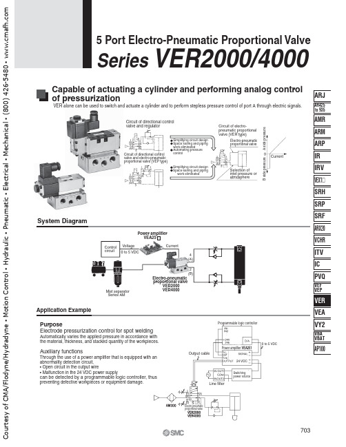
2(B)4(A)5(R1)4(A)2(B)3(R2)1(P)Circuit of directional control valve and regulatorElectro-pneumatic proportional valveSelection of inlet pressure or atmosphereA s i d e p r e s s u r eB s i d e p r e s s u r eCurrentSystem DiagramVEA25VER2000VER4000Circuit of directional control valve and electro-pneumatic proportional valve (VEP type)Circuit of electro-pneumatic proportional valve (VER type)Application ExamplePurposeElectrode pressurization control for spot weldingAutomatically varies the applied pressure in accordance with the material, thickness, and stacked quantity of the workpieces.Auxiliary functionsThrough the use of a power amplifier that is equipped with an abnormality detection circuit,• Open circuit in the output wire• Malfunction in the 24 VDC power supplycan be detected by a programmable logic controller, thus preventing defective workpieces or equipment damage.Control circuitVoltage 0 to 5 VDCCurrentElectro-pneumatic proportional valveMist separator Series AMProgrammable logic controller0 to 5 VDCPower amplifier VEA25124 VDC Switching power sourceOutput cableLine filterElectro-pneumatic proportional valve7035 Port Electro-Pneumatic Proportional ValveSeries VER2000/4000Capable of actuating a cylinder and performing analog control of pressurizationVER alone can be used to switch and actuate a cylinder and to perform stepless pressure control of port A through electric signals.C o u r t e s y o f C M A /F l o d y n e /H y d r a d y n e ▪ M o t i o n C o n t r o l ▪ H y d r a u l i c ▪ P n e u m a t i c ▪ E l e c t r i c a l ▪ M e c h a n i c a l ▪ (800) 426-5480 ▪ w w w .c m a f h .c o m5(R1)1(P)3(R2)4(A)2(B)5(R1)1(P)3(R2)4(A)2(B)VER4000VER20001 AVEA25 ManifoldJIS SymbolCan be made into manifold with series “VV72”.“VER2000” is V type.(Refer to Best Pneumatics No. 1 for further information.)Proportional Solenoid SpecificationsApplicable power amplifier Coil resistanceMax. currentRated power consumption Coil insulation type Max. temperature rise Electrical entry13 W (Ambient temperature 20°C, with maximum current)13 Ω (Ambient temperature 20°C)Class H or equivalent (180°C)140°C (Ambient temperature 50°C, with maximum current)DIN terminal704Series VER2000/V4000C o u r t e s y o f C M A /F l o d y n e /H y d r a d y n e ▪ M o t i o n C o n t r o l ▪ H y d r a u l i c ▪ P n e u m a t i c ▪ E l e c t r i c a l ▪ M e c h a n i c a l ▪ (800) 426-5480 ▪ w w w .c m a f h .c o m5(R1)4(A)1(P)2(B)3(R2)3 (R2)4(A)4 (A)1(P)2(B)2 (B)Working PrincipleIn w , port 3(R) is half open.Example) VER4000-03·····················1 pc.∗ ARB310-00-B ·················1 pc.∗ G36-10-01·······················1 pc.Note) To order valve with interface regulator (B port regulation), flow control interface, orpressure gauge, indicate part number of the electro-pneumatic proportional valve and that of the option ∗. Refer to “Option” on page 704 for part number of option. Products will be in the same package and not assembled when delivered.OFF stateF1 < F2 condition: See figure q .ON stateImmediatelyafter turning on — F1 > F2: See figure e .Thereafter — F1 = F2: See figure w .F1:The pulling force of the solenoid when a specified amperage isapplied to the solenoid, or the force that is created by the pilot pressure.F2:The force that is ceated by the port 4 pressure (P A ) that passesthrough the feedback passage and acts on the spool surface, and the spring force.705Series VER2000/40005 Port Electro-Pneumatic Proportional ValveHow to OrderC o u r t e s y o f C M A /F l o d y n e /H y d r a d y n e ▪ M o t i o n C o n t r o l ▪ H y d r a u l i c ▪ P n e u m a t i c ▪ E l e c t r i c a l ▪ M e c h a n i c a l ▪ (800) 426-5480 ▪ w w w .c m a f h .c o mBe sure to read before handling.Refer to front matters 42 and 43 forSafety Precautions and pages 287 to291 for Precautions on every series.proportional valve is affected by the load capacity.Therefore, select an electro-pneumaticproportional valve in accordance with the bore andthe stroke of the cylinder to be used.(The diagram below is provided as a guide.)amplifier VEA25 . (If NULL and GAIN are in the1 A can be viewed bysubstituting them with command signals 0 to 5 V.)Current ACurrent AOutletpressure(MPa)Outletpressure(MPa)UnapplicableareaBore size (ømm)Applicable areaApplicable areaWiringWiring procedure1.Loosen the retaining screw and pull out theconnector from the pin plug.2.Make sure to remove the retaining screw, insertthe tip of a flat head screwdriver into the groovebelow the terminal block and pry it up toseparate the terminal cover from the terminalblock.3.Securely connect the wires to the specifiedterminals in accordance with the wiringprocedure.T erminal blockConnection 3 is not usedfor terminal 1 and 2.Note) Coil has no polarity.Pin plug shapeApplicable cable (Cabtire cable)0.75 mm2, 1.25 mm2/2 core, 3 core (O.D. ø6.8 toø11.5) based on JIS C 3312 and C 3322.Outlet changing procedureTo change the wire outlet, first separate theterminal cover from the terminal block. Then,reinstall the terminal cover in the desired direction(in 90° increments).Caution1.Air supplyPoor quality air could increase the spool’ssliding resistance, while preventing it fromattaining its specified characteristics. Usecompressor oil with a minimal generation ofoxidants and install a mist separator(SMC’s AM series). Refer to pages 2 and 3.Avoid using ultra-dry air since it mayreduce the amount of lubricant and shortenthe service life.2. MountingVibrations are transmitted to the valve bythe proportional solenoid’s dither. If it isnecessary to prevent the transmission ofvibrations, insert vibration isolating rubbermaterial.Thoroughly flush the pipe to completelyeliminate any dust or scales from the pipeinside.Install a silencer (AN series) on the exhaustport.Be careful with the molded coil because itgenerates heat while current is applied toit.3.LubricationThis product can be used without lubrication.But if lubricated, use turbin oil Class 1, ISOVG32 (with no additive). It is impossible touse spindle oil, machine oil, or grease.4.Manual operationTo check the operation of the valve withoutapplying a current, remove the lock nut anduse a screwdriver or the like to press the tipof the core. After checking the operation,reinstall the rubber cap in its original position.Cylinderstroke(st/mm)706SeriesVER2000/V4000CourtesyofCMA/Flodyne/Hydradyne▪MotionControl▪Hydraulic▪Pneumatic▪Electrical▪Mechanical▪(8)426-548▪www.cmafh.comVER2000VER4000Construction707Series VER2000/40005 Port Electro-Pneumatic Proportional ValveC o u r t e s y o f C M A /F l o d y n e /H y d r a d y n e ▪ M o t i o n C o n t r o l ▪ H y d r a u l i c ▪ P n e u m a t i c ▪ E l e c t r i c a l ▪ M e c h a n i c a l ▪ (800) 426-5480 ▪ w w w .c m a f h .c o mMounting hole(For M6)VER4000VER4001DimensionsWith flow control interface With B port regulator 708Series VER2000/4000Mounting hole(For M6)(Max.189.5)(Max. 45)(Max. 45)(Max. 45)InterfaceregulatorFlow controlinterfaceFlow controlinterfaceExternalpilot port(VER4001)CourtesyofCMA/Flodyne/Hydradyne▪MotionControl▪Hydraulic▪Pneumatic▪Electrical▪Mechanical▪(8)426-548▪www.cmafh.comRc,VER 000-A0.1 to 0.9MPaVEA250, VEA251DIN terminalVS7-8-FG-S-3N42381242DXT334-X72-04R-04U5 Port Electro-Pneumatic Proportional ValveRelated Products:A solenoid valve for actuating acylinder and an electro-pneumaticproportional valve for pressure controlhave been integrated into a single unit.High response has been achieved.The size and the direction of the pipeport can be selected.The size of the electro-pneumatic proportioncan be selected.Solenoid valves for actuating a 2 stagestroke gun cylinder or a clamp cylinder canbe mounted on an integrated manifold(maximum of 8 stations).ConstructionCylinderControldeviceMist separator Air supplyCircuit (Basic unit: DXT334-X7)12SpecificationsStationsPort sizeSolenoid valves (8 stations at max.) can be added to the basic unit (2 stations). Note)Note) Composed of basic unit (VER000-A, VS7-8-FG-S-3N)Refer to Best Pneumatics No. 1 for details about solenoid valve.Set pressure range of A portPower amplifierWiringNote)Note) In the case of VER4000, set the inlet pressure by 0.05 MPa or higher thanthe reguired maximum set pressure.Rated voltageWiring24 VDC (–15% to + 10%)DIN terminalHow to OrderOrdering exampleDXT334-X711-04R-04U··············1 pc.VS7-8-FG-D-3M ·························1 pc.(Third station of manifold where 1 piece of “VS7-8-FG-D-3M” is added to thebasic unit of “VER2000-A” and “VS7-8-FG-S-3N”.)Dimensions122 x RcExhaust portU sideR sideL sideD sideRc 1/2 supply port (L side)2 x Rc 1/2, Output port709 CourtesyofCMA/Flodyne/Hydradyne▪MotionControl▪Hydraulic▪Pneumatic▪Electrical▪Mechanical▪(8)426-548▪www.cmafh.com。
艾顿Moeller系列快速链接DOL电机启动器说明说明书

Eaton 198520Eaton Moeller® series Rapid Link - DOL starter, 6.6 A, Sensor input 2, 230/277 V AC, AS-Interface®, S-7.4 for 31 modules, HAN Q5, with manual override switchGeneral specificationsEaton Moeller® series Rapid Link DOL starter1985204015081963959RAMO5-D202A31-512RS1120 mm 270 mm 220 mm 1.8 kgCCC CE RoHS UL 60947-4-2 UL approval IEC/EN 60947-4-2Assigned motor rating: for normal internally and externally ventilated 4 pole, three-phase asynchronous motors with 1500 rpm at 50 Hz or 1800 min at 60 HzProduct NameCatalog NumberEANModel CodeProduct Length/Depth Product Height Product Width Product Weight Certifications Catalog NotesParameterization: FieldbusParameterization: KeypadDiagnostics and reset on device and via AS-Interface Parameterization: drivesConnectParameterization: drivesConnect mobile (App)Key switch position AUTOKey switch position HANDManual override switchShort-circuit releaseThermo-clickElectronic motor protectionKey switch position OFF/RESETThermistor monitoring PTCTwo sensor inputs through M12 sockets (max. 150 mA) for quick stop and interlocked manual operationExternal reset possibleFor actuation of motors with mechanical brakeTemperature compensated overload protection CLASS 10 AIP65NEMA 12Class A10,000,000 Operations (at AC-3)10,000,000 Operations (at AC-3)Direct starter0.3 A6.6 AIIIMotor starterAS-Interface profile cable: S-7.4 for 31 modulesASI4000 VPhase-earthed AC supply systems are not permitted. AC voltageCenter-point earthed star network (TN-S network) DOL starterDCFeatures Fitted with: Functions ClassDegree of protectionElectromagnetic compatibility Lifespan, electricalLifespan, mechanicalModelOverload release current setting - min Overload release current setting - max Overvoltage categoryProduct categoryProtocolRated impulse withstand voltage (Uimp) System configuration typeTypeVoltage typeVertical15 g, Mechanical, According to IEC/EN 60068-2-27, 11 ms, Half-sinusoidal shock 11 ms, 1000 shocks per shaftResistance: 10 - 150 Hz, Oscillation frequencyResistance: According to IEC/EN 60068-2-6Resistance: 6 Hz, Amplitude 0.15 mmResistance: 57 Hz, Amplitude transition frequency on acceleration Max. 2000 mAbove 1000 m with 1 % performance reduction per 100 m Max. 1000 m-10 °C55 °C-40 °C70 °CIn accordance with IEC/EN 50178< 95 %, no condensation0.3 - 6.6 A, motor, main circuit Adjustable, motor, main circuit6.6 A (at 150 % Overload)Maximum of one time every 60 seconds380 - 480 V (-15 %/+10 %, at 50/60 Hz)20 - 35 ms20 - 35 ms50/60 HzAC-53a 3 HP≤ 0.6 A (max. 6 A for 120 ms), Actuator for external motor brake230/277 V AC -15 % / +10 %, Actuator for external motor brake10 kA0 AType 1 coordination via the power bus' feeder unit, Main circuitMounting position Shock resistance Vibration AltitudeAmbient operating temperature - min Ambient operating temperature - max Ambient storage temperature - min Ambient storage temperature - max Climatic proofingCurrent limitationInput currentMains switch-on frequency Mains voltage tolerance Off-delayOn-delayOutput frequency Overload cycleRated frequency - min Assigned motor power at 460/480 V, 60 Hz, 3-phaseBraking currentBraking voltageRated conditional short-circuit current (Iq)Rated conditional short-circuit current (Iq), type 2, 380 V, 400 V, 415 VShort-circuit protection (external output circuits)47 Hz63 Hz6.6 A6.6 A6.6 A0.09 kW3 kW0 kW3 kW480 V AC, 3-phase 400 V AC, 3-phase 50/60 Hz, fLN, Main circuit Phase-earthed AC supply systems are not permitted. AC voltageCenter-point earthed star network (TN-S network)0 V0 V0 V0 V0 V0 V24 V DC (-15 %/+20 %, external via AS-Interface® plug) 230/277 V AC (external brake 50/60 Hz)Connections pluggable in power section Specification: S-7.4 (AS-Interface®)Number of slave addresses: 31 (AS-Interface®)Max. total power consumption from AS-Interface® power supply unit (30 V): 190 mA10 m, Radio interference level, maximum motor cable lengthMeets the product standard's requirements.Meets the product standard's requirements.Rated frequency - max Rated operational current (Ie)Rated operational current (Ie) at 150% overload Rated operational current (Ie) at AC-3, 380 V, 400 V, 415 V Rated operational power at 380/400 V, 50 Hz - min Rated operational power at 380/400 V, 50 Hz - max Rated operational power at AC-3, 220/230 V, 50 Hz Rated operational power at AC-3, 380/400 V, 50 Hz Rated operational voltage Supply frequencySystem configuration typeRated control supply voltage (Us) at AC, 50 Hz - min Rated control supply voltage (Us) at AC, 50 Hz - max Rated control supply voltage (Us) at AC, 60 Hz - min Rated control supply voltage (Us) at AC, 60 Hz - max Rated control supply voltage (Us) at DC - min Rated control supply voltage (Us) at DC - max Rated control voltage (Uc)ConnectionInterfacesNumber of auxiliary contacts (normally closed contacts)Number of auxiliary contacts (normally open contacts)Cable length10.2.2 Corrosion resistance10.2.3.1 Verification of thermal stability of enclosuresMeets the product standard's requirements.Meets the product standard's requirements.Meets the product standard's requirements.Does not apply, since the entire switchgear needs to be evaluated.Does not apply, since the entire switchgear needs to be evaluated.Meets the product standard's requirements.Does not apply, since the entire switchgear needs to be evaluated.Meets the product standard's requirements.Does not apply, since the entire switchgear needs to be evaluated.Does not apply, since the entire switchgear needs to be evaluated.Is the panel builder's responsibility.Is the panel builder's responsibility.Is the panel builder's responsibility.Is the panel builder's responsibility.Is the panel builder's responsibility.The panel builder is responsible for the temperature rise Generation change from RA-SP to RASP 4.0Connecting drives to generator suppliesGeneration change RAMO4 to RAMO5Generation change from RA-MO to RAMO 4.0Generation Change RASP4 to RASP5Configuration to Rockwell PLC for Rapid LinkElectromagnetic compatibility (EMC)Generation Change RA-SP to RASP5Rapid Link 5 - brochureDA-SW-USB Driver DX-COM-STICK3-KITDA-SW-drivesConnectDA-SW-drivesConnect - installation helpDA-SW-USB Driver PC Cable DX-CBL-PC-1M5DA-SW-Driver DX-CBL-PC-3M0DA-SW-drivesConnect USB Driver DX-COM-PCKITDA-SW-drivesConnect - InstallationshilfeMaterial handling applications - airports, warehouses and intra-logisticsProduct Range Catalog Drives EngineeringDA-DC-00004184.pdfDA-DC-00004525.pdfDA-DC-00003964.pdfDA-DC-00004523.pdfeaton-bus-adapter-rapidlink-reversing-starter-dimensions-002.eps eaton-bus-adapter-rapidlink-reversing-starter-dimensions-003.eps eaton-bus-adapter-rapidlink-speed-controller-dimensions-003.eps eaton-bus-adapter-rapidlink-speed-controller-dimensions-002.epsETN.RAMO5-D202A31-512RS1.edzIL034084ZU10.2.3.2 Verification of resistance of insulating materials to normal heat10.2.3.3 Resist. of insul. mat. to abnormal heat/fire by internal elect. effects10.2.4 Resistance to ultra-violet (UV) radiation10.2.5 Lifting10.2.6 Mechanical impact10.2.7 Inscriptions10.3 Degree of protection of assemblies10.4 Clearances and creepage distances10.5 Protection against electric shock10.6 Incorporation of switching devices and components10.7 Internal electrical circuits and connections10.8 Connections for external conductors10.9.2 Power-frequency electric strength10.9.3 Impulse withstand voltage10.9.4 Testing of enclosures made of insulating material10.10 Temperature rise Application notes BrochuresCatalogs Certification reportsDrawingseCAD model Installation instructions Installation videosEaton Corporation plc Eaton House30 Pembroke Road Dublin 4, Ireland © 2023 Eaton. All Rights Reserved. Eaton is a registered trademark.All other trademarks areproperty of their respectiveowners./socialmediacalculation. Eaton will provide heat dissipation data for the devices.Is the panel builder's responsibility. The specifications for the switchgear must be observed.Is the panel builder's responsibility. The specifications for the switchgear must be observed.The device meets the requirements, provided the information in the instruction leaflet (IL) is observed.Rapid Link 5MN040003_EN MN034004ENramo5_v4.stp ramo5_v4.dwg10.11 Short-circuit rating10.12 Electromagnetic compatibility 10.13 Mechanical function Manuals and user guides mCAD model。
PROFITEST 204 + PROFITEST 204 HP-2,5kV Tester for …

Int. Resist. RI
Meas. Uncertainty
Intrinsic Uncertainty
Overload Capacity Duration
0 85 m 100 Protective 10 330 m 85 999 m 1 m Conductor Resistance 1.00 9.99 1.00 9.99 10 m RSL 10.0 25.0 10.0 25.0 100 m
PROFITEST 204+ / PROFITEST 204HP-2,5kV Tester for DIN EN 60204-1 and VDE 0113-1, EN 61439-1 and VDE 0660-600-1
3-348-802-03 21/8.14
• • • • • • • • • •
1200 V
cont.
—
1 M 10 M
—
(5% rdg. +2 d) (10% rdg. +2 d) (20% rdg. +2 d)
0.00 9.99 mA
0.2 9.9 mA 0.01 mA
—
—
—
—
2 k (8.6% rdg. +9 d) (5% rdg. + 5 d)
250 V
U 2)
(3% rdg. + 5 d)
0 9.99 V* 10.0 12.0 V 0 999 k
—
0.01 V 0.1 V 1 k 100 k 1 M
M2 LED Troffer安装说明书
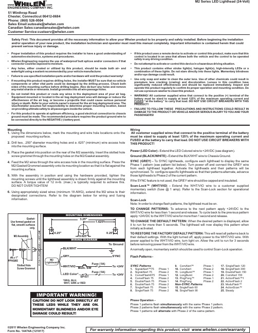
Mountinging the dimensions below,mark the mounting and wire hole locations onto the proposed mounting surface.2.Drill two,.250"diameter mounting holes and a .625"(minimum)wire access hole into the mounting surface.3.Place the gasket into position on the rear of the M2assembly.Insert the slotted hole screw grommet through the mounting holes on the M2/Gasket assembly.4.Feed the M2wires through the wire access hole in the mounting surface.Press the M2/Gasket/Grommet assembly onto its mounting location so that it is flat against the mounting surface.5.With the assembly in position and using the hardware provided,tighten the mounting screws until the lighthead assembly is drawn firmly against the mounting surface.A torque value of 12in-lb.(max.)is typically required to achieve this.DO NOT OVER TIGHTEN!ing appropriately sized wires (minimum 18AWG),extend the M2wires to their designated connections.Refer to the diagram below for wiring and fusing information.©2011 Whelen Engineering Company Inc.Form No. 14474A (121817)M2 Series LED Lighthead (24-Volt)For warranty information regarding this product, visit /warrantyWiringAll customer supplied wires that connect to the positive terminal of the battery must be sized to supply at least 125%of the maximum operating current and FUSED at the battery to carry that load.DO NOT USE CIRCUIT BREAKERS WITH THIS PRODUCT!Power (LED Color)-Extend the LED Colored wire to +24VDC (see diagram).Ground (BLACK/WHITE)-Extend the BLK/WHT wire to Chassis Ground.SYNC (GREY)-To SYNC lightheads,configure each lighthead to display the same Phase 1pattern (see pattern list below).Turn power off and connect the GREY wire from each lighthead together.Activate the lightheads and their patterns will be synchronized.To configure specific lightheads so that their patterns alternate,advance those lightheads to Phase 2of the current pattern.If the SYNC feature is not used,the GREY wire should be capped and insulated.Scan-Lock™(WHT/VIO)-Extend the WHT/VIO wire to a customer supplied momentary switch (fuse @1amp).Refer to the Scan-Lock section for operational information.Scan-LockNote:In order to change flash patterns,the lighthead must be on.TO CHANGE PATTERNS:To advance to the next pattern apply +24VDC to the WHT/VIO wire for less than 1second and release.To cycle back to the previous pattern apply +24VDC to the WHT/VIO wire for more than 1second and release.TO CHANGE THE DEFAULT PATTERN:When the desired pattern is displayed,allow it to run for more than 5seconds.The lighthead will now display this pattern when initially activated.TO RESTORE THE FACTORY DEFAULT PATTERN:This will reset all patterns back to their default settings.With the light turned off,apply power to the WHT/VIO wire.With power applied to the WHT/VIO wire,turn light on.Allow the unit to run for 3seconds before removing power from the WHT/VIO wire.Anormally open,momentary switch should be used to control Scan-Lock operation.Flash Patterns -SYNC Patterns1.SignalAlert™75Phase 12.SignalAlert 75Phase 2etFlash®75Phase 1etFlash 75Phase 25.DoubleFlash 75Phase 16.DoubleFlash 75Phase 27.SingleFlash 75Phase 18.SingleFlash 75Phase 2Alert™Phase Alert Phase 211.LongBurst™Phase 112.LongBurst Phase 213.PingPong™Phase 114.PingPongPhase 2Non-SYNC Patterns15.SingleFlash 6016.SingleFlash 9017.SingleFlash 12018.SingleFlash 30019.DoubleFlash Alert 15021.ActionFlash™122.ActionFlash 223.ModuFlash™24.ActionScan™25.SteadyPhase Operation -Phase 1 patterns flash with the same Phase 1 pattern.simultaneously Phase 2 patterns flash with the same Phase 2 pattern.simultaneously Phase 1 patterns will with Phase 2 of the same pattern.alternateSafety First: This document provides all the necessary information to allow your Whelen product to be properly and safely installed. Before beginning the installation and/or operation of your new product, the installation technician and operator must read this manual completely. Important information is contained herein that could prevent serious injury or damage.•Proper installation of this product requires the installer to have a good understanding of automotive electronics,systems and procedures.•Whelen Engineering requires the use of waterproof butt splices and/or connectors if that connector could be exposed to moisture.•Any holes,either created or utilized by this product,should be made both air-and watertight using a sealant recommended by your vehicle manufacturer.•Failure to use specified installation parts and/or hardware will void the product warranty!•If mounting this product requires drilling holes,the installer MUST be sure that no vehicle components or other vital parts could be damaged by the drilling process.Check both sides of the mounting surface before drilling begins.Also de-burr any holes and remove any metal shards or remnants.Install grommets into all wire passage holes.•Do not install this product or route any wires in the deployment area of your air bag.Equipment mounted or located in the air bag deployment area will damage or reduce the effectiveness of the air bag,or become a projectile that could cause serious personal injury or death.Refer to your vehicle owner's manual for the air bag deployment area.The User/Installer assumes full responsibility to determine proper mounting location,based on providing ultimate safety to all passengers inside the vehicle.•For this product to operate at optimum efficiency,a good electrical connection to chassis ground must be made.The recommended procedure requires the product ground wire to be connected directly to the NEGATIVE (-)battery post.•If this product uses a remote device to activate or control this product,make sure that this control is located in an area that allows both the vehicle and the control to be operated safely in any driving condition.•Do not attempt to activate or control this device in a hazardous driving situation.•This product contains either strobe light(s),halogen light(s),high-intensity LEDs or a combination of these lights.Do not stare directly into these lights.Momentary blindness and/or eye damage could result.•Use only soap and water to clean the outer e of other chemicals could result in premature lens cracking (crazing)and discoloration.Lenses in this condition have significantly reduced effectiveness and should be replaced immediately.Inspect and operate this product regularly to confirm its proper operation and mounting condition.Do not use a pressure washer to clean this product.•WARNING!All customer supplied wires that connect to the positive (+)terminal of the battery must be sized to supply at least 125%of the maximum operating current and FUSED “at the battery”to carry that load.DO NOT USE CIRCUIT BREAKERS WITH THIS PRODUCT!•FAILURE TO FOLLOW THESE PRECAUTIONS AND INSTRUCTIONS COULD RESULT IN DAMAGE TO THE PRODUCT OR VEHICLE AND/OR SERIOUS INJURY TO YOU AND YOUR PASSENGERS!®ENGINEERING COMPANY INC.51 Winthrop RoadChester, Connecticut 06412-0684Phone: (860) 526-9504SalesEmail:*******************CanadianSales:************************CustomerService:*******************www..comWarnings to InstallersWhelen’s emergency vehicle warning devices must be properly mounted and wired in order to be effective and safe. Read and follow all of Whelen’s written instructions when installing or using this device. Emergency vehicles are often operated under high speed stressful conditions which must be accounted for when installing all emergency warning devices. Controls should be placed within convenient reach of the operator so that he can operate the system without taking his eyes off the roadway. Emergency warning devices can require high electrical voltages and/or currents. Properly protect and use caution around live electrical connections.Grounding or shorting of electrical connections can cause high current arcing, which can cause personal injury and/or vehicle damage, including fire. Many electronic devices used in emergency vehicles can create or be affected by electromagnetic interference.Therefore, after installation of any electronic device it is necessary to test all electronic equipment simultaneously to insure that they operate free of interference from other components within the vehicle. Never power emergency warning equipment from the same circuit or share the same grounding circuit with radio communication equipment.All devices should be mounted in accordance with the manufacturer’s instructions and securely fastened to vehicle elements of sufficient strength to withstand the forces applied to the device. Driver and/or passenger air bags (SRS) will affect the way equipment should be mounted.This device should be mounted by permanent installation and within the zones specified by the vehicle manufacturer, if any.Any device mounted in the deployment area of an air bag will damage or reduce the effectiveness of the air bag and may damage or dislodge the device. Installer must be sure that this device, its mounting hardware and electrical supply wiring does not interfere with the air bag or the SRS wiring or sensors. Mounting the unit inside the vehicle by a method other than permanent installation is not recommended as unit may become dislodged during swerving; sudden braking or collision. Failure to follow instructions can result in personal injury. Whelen assumes no liability for any loss resulting from the use of this warning device. PROPER INSTALLATION COMBINED WITH OPERATOR TRAINING IN THE PROPER USE OF EMERGENCY WARNING DEVICES IS ESSENTIAL TO INSURE THE SAFETY OF EMERGENCY PERSONNEL AND THE PUBLIC.Warnings to UsersWhelen’s emergency vehicle warning devices are intended to alert other operators and pedestrians to the presence and operation of emergency vehicles and personnel. However, the use of this or any other Whelen emergency warning device does not guarantee that you will have the right-of-way or that other drivers and pedestrians will properly heed an emergency warning signal. Never assume you have the right-of-way. It is your responsibility to proceed safely before entering an intersection, driving against traffic, responding at a high rate of speed, or walking on or around traffic lanes. Emergency vehicle warning devices should be tested on a daily basis to ensure that they operate properly. When in actual use, the operator must ensure that both visual and audible warnings are not blocked by vehicle components (i.e.: open trunks or compartment doors), people, vehicles, or other obstructions. It is the user’s responsibility to understand and obey all laws regarding emergency warning devices.The user should be familiar with all applicable laws and regulations prior to the use of any emergency vehicle warning device. Whelen’s audible warning devices are designed to project sound in a forward direction away from the vehicle occupants. However, because sustained periodic exposure to loud sounds can cause hearing loss, all audible warning devices should be installed and operated in accordance with the standards established by the National Fire Protection Association.。
津上va2参数

津上VA2参数介绍津上VA2参数是指用于津上公司生产的VA2系列产品的参数设置。
津上VA2是一种新型智能设备,可应用于各种复杂的场景,提供高效、稳定的解决方案。
正确的参数设置是确保设备正常运行和实现所需功能的关键。
参数设置的重要性正确设置津上VA2的参数是设备正常运行的基础。
参数设置错误可能导致设备无法正常工作,甚至造成严重的故障。
因此,合理的参数设置对于设备的性能和稳定性非常重要。
常用参数及设置方法1. 通信参数设置•连接方式:选择合适的通信方式,如以太网、Wi-Fi等。
•IP地址设置:根据实际需求设置合适的IP地址,确保设备能与其他设备正常通信。
•子网掩码设置:根据网络环境的需要,设置正确的子网掩码。
•网关设置:设置正确的网关地址,确保设备的网络通信正常。
2. 数据采集参数设置•采集频率:根据需求设置数据采集的频率,确保采集到足够的数据。
•采集量程:根据被测对象的类型和范围,设置适当的采集量程。
•采集模式:选择合适的采集模式,如连续采集、触发采集等。
3. 控制参数设置•控制方式:选择合适的控制方式,如自动控制、手动控制等。
•控制逻辑:根据被控制对象的特点和需求,设置合适的控制逻辑,如PID控制、模糊控制等。
•控制参数调整:根据实际情况,对控制参数进行适当调整,确保控制效果良好。
4. 报警参数设置•报警条件设置:根据需要设置合适的报警条件,如温度超过设定值、湿度低于设定值等。
•报警方式设置:选择合适的报警方式,如声音报警、短信报警等。
•报警级别设置:根据紧急程度,设置不同的报警级别,以便及时采取相应的措施。
设置步骤1.连接设备:将津上VA2与电源和通信线连接好。
2.进入参数设置界面:打开设备的监控软件,进入参数设置界面。
3.选择需要设置的参数:根据具体需求,选择需要设置的参数类别。
4.输入参数数值:根据设备的要求,输入正确的参数数值。
5.保存参数设置:确认参数无误后,保存设置并退出参数设置界面。
- 1、下载文档前请自行甄别文档内容的完整性,平台不提供额外的编辑、内容补充、找答案等附加服务。
- 2、"仅部分预览"的文档,不可在线预览部分如存在完整性等问题,可反馈申请退款(可完整预览的文档不适用该条件!)。
- 3、如文档侵犯您的权益,请联系客服反馈,我们会尽快为您处理(人工客服工作时间:9:00-18:30)。
DAIMLERCHRYSLERProcess Procedure , POS EnginesVAM00223 Key Characteristics Page 1 of 5 0 Distribution List: PBE/PLD PBE/PPR PBE/PM PBE/PE PBE/PMM E/PHM PBE/PMS E/PHA PBE/PT PBE/PTA PBE/PTM PBE/PTS PBE/PQE PBE/PQT PBE/D PBE/PLC PBE/DM PBE/DH PBE/DHD1Purpose Description of procedure for specifying and handling key characteristics Scope of Application On-highway engine power systems Terms KC FMEA D-FMEA23P-FMEAKey characteristics Failure mode and effects analysis System FMEA for "design" or "product" (The two variants merge at the interface from the overall system to the individual component.) System FMEA for "process" (This variant looks at the possible risks involved in manufacturing and assembly processes.)4Responsibilities Cross-departmental team: composed of representatives from the Development, Engineering, Production, Quality Management and Sales departments Description Identification of KCs5 5.1All product characteristics are essentially important and must be monitored. However, certain characteristics must be subjected to particular checks, as they affect: • Safety (e.g. danger to user in the case of a failure) • Statutory requirements (e.g. emissions) • Functionality (e.g. availability, performance, service life requirements) • Appearance (e.g. surface characteristics)Published: Replaced: File: 11.03.2002 08.06.1999 VAM00223.doc Prepared by: Jörg Schneider, PBE/QMT Approved by: Thomas StengelDAIMLERCHRYSLERProcess Procedure , POS EnginesVAM00223 Key Characteristics Page 2 of 5 • Increased expenditure and/or complexity in process design and the process cycle, or the ease of assembly (e.g. in the case of deviations in dimensions) more heavily than others.Specification as a KC is necessary or advisable: • Where possible consequences of errors take on greater significance (particularly, for example, if a failure cannot be “intercepted” by a redundant design) • In the case of limited permissible distributions of characteristics (even minor deviations constitute non-compliance with the product requirements) • With a highly complex overall system (high level of mutual interaction with effects that are hard to assess) • Where the product is extremely innovative (little empirical evidence); existing KCs from previous products must be applied to a new product of a comparable scope. • Where there is negative empirical evidence for a product or process (critical test or field data for current or previous products or manufacturing/assembly difficulties) • When expressly requested by a customer. The identification of KCs should be performed by a cross-departmental team of representatives from Development (Design and Testing), Engineering, Production (Manufacturing and Assembly), Quality Management and Sales ("voice of the customer"). These activities must be organized in the form of product projects. In the event of (retrospective) requests for changes or additions to the KCs by one of the parties involved, the exchange of information with the other disciplines must be ensured. Similarly to the above points, the identification and handling of KCs by suppliers must be agreed and specified in the Requirement Specifications as part of project processing. In the case of explicit customer requirements and other cases with identifiable cost implications, KCs must be negotiated via AEMA/KAEA. 5.2 Supportive Methods for Identifying KCsThe identification of KCs can usefully be combined with the creation of risk analyses in the form of FMEAs (D- or P-FMEA) and/or other risk assessment methods (e.g. 8D method). The assessment is similar and the same parties are generally required to process the assessment. The FMEA parameters can serve as a guide (e.g. high B grades indicate serious consequences of errors, while high A grades indicate problematical design or process parameters). However, using FMEA parameters as the sole basis is not advisable, as the above assessment criteria extend far beyond the criteria that can be shown in the FMEA assessment. Characteristics with a rating > 5 in at least one of the FMEA individual parameters (B, A, E), should be checked with regard to classification as a KC (taking into account other criteria with a 0 rating).11.03.02DAIMLERCHRYSLERProcess Procedure , POS EnginesVAM00223 Key Characteristics Page 3 of 5 The exchange of information between Development and Manufacturing/Assembly about the respective characteristics identified must be ensured, i.e. characteristics identified in the context of a D-FMEA (in Development) as relevant to KCs must be forwarded, just as KCs identified in the context of a P-FMEA are to be fed back to Development. 5.3 Identification and Tracking of KCsKCs are only shown in drawings (including text drawings) and engine acceptance sheets and are updated by Development. KCs are identified by means of the symbol in the drawing and bold type in the engine acceptance sheets. KCs are then incorporated into test specifications, test drawings and test plans at the production plant. KCs are recorded randomly during production and evaluated statistically by QME.11.03.02DAIMLERCHRYSLERProcess Procedure, Powertrain Business Unit EnginesKey CharacteristicsVAM 00223 Page 4 of 55.4Overall Process for Specifying and Tracking a KC6Other Applicable Documents VAM00054 Procedure for specifying production processes VAM00065 Quality planning of in-house parts VAM00228 Project management Annexes None08.06.1999 VAM00223.doc Prepared by: Henner Wolf Approved by: Thomas Stengel7Published: Replaced: File:DAIMLERCHRYSLER«Type», Powertrain Business Unit EnginesKey CharacteristicsVAM 00223 Page 5 of 5Published: Replaced: File:08.06.1999 VAM00223.docPrepared by: «Author»«Approved by»: «Approved_by»。