PandAP系列温控器说明书V1.1
恒温控制器操作指南说明书
Step 11. Enter to the Thermocouple Type Input Submenu Press d to display flashing, previously selected Thermocouple type.Step 12. Scroll through available selection of TC types Press b to sequence thru flashing Thermocouple types,(select k -for type "K" CHROMEGA TM /ALOMEGA TM )J K T E N DIN J R S B C - TC types J k t E N dN J R S b C - DisplayStep 13. Store TC typeAfter you have selected the Thermocouple type press d to store your selection, the instrument automatically advances to the next menu item.Step 14. Enter to Reading Configuration MenuThe display shows RDG Reading Configuration, which is the top menu for 4 submenus: Decimal Point, Degree Units, Filter Constant and Input/Reading Submenus.Step 15. Enter to Decimal Point Submenu Press dto show DEC Decimal Point.Step 16. Display the Decimal Point positionPress d again to display the flashing Decimal Point position.Step 17. Select the Decimal Point position Press b to select FFF.F Decimal Point position.Step 18. Store selected Decimal Point positionBy pressing d momentarily the Decimal Point position will be stored and the instrument will go to the next menu item.Step 19. Enter to Temperature Unit Submenu Display shows TEMP Temperature Unit.Step 20. Display available Temperature Units Press d to display the flashing Degree °F or °C .Step 21. Scroll through Temperature Units selection Press b to select °F Degree.Step 22. Store the Temperature UnitPress d to display momentarily that the Degree Unit has been stored and the instrument will go automatically to the next menu item.Step 23. Enter the Filter Constant Submenu Display shows FLTR Filter Constant Submenu.Step 24. Display the Filter Constant Value Submenu Press d to display the flashing, previously selected Filter Constant.Step 25. Scroll through available Filter Constants Press b to sequence thru Filter Constants 0001, 0002,0004, 0008, 0016, 0032, 0064and 0128.Step 26. Store the Filter ConstantPress d momentarily to store 0004Filter Constant and the instrument will automatically go to the next menu item.Step 27. Enter Alarm 1 MenuPress a until the ALR1Alarm 1 Menu appears on the Display. In the following steps we are going to DisableLatch, Active Above, Deadband 020.0, and above Setpoint 1Value will activate Alarm 1.Step 28. Select Latch Type SubmenuPress d to display flashing DSBL / ENBL .If flashing DSBL is displayed, press a , if ENBL is displayed, press b until DSBL is displayed, then press d to store and go to the next menu item.Step 29. Select the Above Type of Active Submenu Press d . If flashing ABoV Above is displayed, press a ,otherwise press b until ABoV is displayed. Press d to store and advance to next menu item.WARRANTY/DISCLAIMEROMEGA ENGINEERING, INC. warrants this unit to be free of defects in materials and workmanship for a period of 61 months from date of purchase. OMEGA’s WARRANTY adds an additional one (1) month grace period to the normal five (5) year product warranty to cover handling and shipping time. T his ensures that OMEGA’s customers receive maximum coverage on each product.If the unit malfunctions, it must be returned to the factory for evalua-tion. OMEGA’s Customer Service Department will issue an Authorized Return (AR) number immediately upon phone or written request. Upon examination by OMEGA, if the unit is found to be defective, it will be repaired or replaced at no charge. OMEGA’s WARRANTY does not apply to defects resulting from any action of the purchaser, includ-ing but not limited to mishandling, improper interfacing, operation outside of design limits, improper repair, or unauthorized modifica-tion. This WARRANTY is VOID if the unit shows evidence of having been tampered with or shows evidence of having been damaged as a result of excessive corrosion; or current, heat, moisture or vibration; improper specification; misapplication; misuse or other operating conditions outside of OMEGA’s control. Components in which wear is not warranted, include but are not limited to contact points, fuses, and triacs.OMEGA is pleased to offer suggestions on the use of its vari-ous products. However, OMEGA neither assumes responsibil-ity for any omissions or errors nor assumes liability for any damages that result from the use if its products in accordance with information provided by OMEGA, either verbal or writ-ten. OMEGA warrants only that the parts manufactured by the company will be as specified and free of defects. OMEGA MAKES NO OTHER WARRANTIES OR REPRESENTATIONS OF ANY KIND WHATSOEVER, EXPRESSED OR IMPLIED, EXCEPT THAT OF TITLE, AND ALL IMPLIED WARRANTIES INCLUDING ANY W ARRANTY OF MERCHANTABILITY AND FITNESS FOR A PARTICULAR PURPOSE ARE HEREBY DISCLAIMED. LIMITATION OF LIABILITY: The remedies of purchaser set forth herein are exclusive, and the total liability of OMEGA with respect to this order, whether based on contract, warran-ty, negligence, indemnification, strict liability or otherwise, shall not exceed the purchase price of the component upon which liability is based. In no event shall OMEGA be liable for consequential, incidental or special damages.CONDITIONS: Equipment sold by OMEGA is not intended to be used, nor shall it be used: (1) as a “Basic Component” under 10 CFR 21 (NRC), used in or with any nuclear installation or activity; or (2) in medical appli-cations or used on humans. Should any Product(s) be used in or with any nuclear installation or activity, medical application, used on humans, or misused in any way, OMEGA assumes no responsibility as set forth in our basic WARRANT Y/DISCLAIMER language, and, additionally, purchaser will indemnify OMEGA and hold OMEGA harmless from any liability or damage whatsoever arising out of the use of the Product(s) in such a manner.RETURN REQUESTS/INQUIRIESDirect all warranty and repair requests/inquiries to the OMEGA Customer Service Department. BEFORE RE URNING ANY PRODUC (S) O OMEGA, PURCHASER MUS OB AIN AN AUTHORIZED RETURN (AR) NUMBER FROM OMEGA’S CUSTOMER SERVICE DEPART MENT (IN ORDER T O AVOID PROCESSING DELAYS). T he assigned AR number should then be marked on the outside of the return package and on any correspondence.FOR WARRANTY RETURNS, please have the followinginformation available BEFORE contacting OMEGA:1. Purchase Order number under which the product was PURCHASED,2.3. Model and serial number of the product under warranty, and Repair instructions and/or specific problems relative to the product.FOR NON-WARRANTY REPAIRS, consult OMEGA for current repair charges. Have the following information available BEFORE contacting OMEGA:1. P urchase Order number to cover the COST of the repair or calibration,2.3.Model and serial number of the product, and R epair instructions and/or specific problems relative to the product.OMEGA’s policy is to make running changes, not model changes, whenever an improvement is possible. This affords our customers the latest in technology and engineering.OMEGA is a trademark of OMEGA ENGINEERING, INC.© Copyright 2018 OMEGA ENGINEERING, INC. All rights reserved. T his document may not be copied, photocopied, reproduced, translated, or reduced to any electronic medium or machine-readable form, in whole or in part, without the prior written consent of OMEGA ENGINEERING, INC.MQS 3720/0818This Quick Start Reference provides information onsetting up your instrument for basic operation. Thelatest complete Communication and OperationalManual as well as free Software and ActiveXControls are available at or onthe CD-ROM enclosed with your shipment.The instrument is a panel mount device protected in accordance with EN 61010-1:2001, electrical safety requirements for electrical equipment for measurement, control and laboratory.Remember that the unit has no power-on switch. Building installation should include a switch or circuit-breaker that must be compliant to IEC 947-1 and 947-3. SAFETY:•Do not exceed voltage rating on the label located onthe back of the instrument housing.•Always disconnect power before changing signal andpower connections.•Do not use this instrument on a work bench withoutits case for safety reasons.•Do not operate this instrument in flammable orexplosive atmospheres.EMC:•Whenever EMC is an issue, always use shielded cables.•Never run signal and power wires in the same conduit.•Use signal wire connections with twisted-pair cables.•Install Ferrite Bead(s) on signal wire close to theinstrument if EMC problems persist.。
LU-926K记忆型温控器说明书-V1.1

V1.1LU-926K目 录一、概述---------------------------------------------------------------------------------------------------1二、主要技术参数---------------------------------------------------------------------------------------2三、输出接口模块---------------------------------------------------------------------------------------4四、型号定义说明---------------------------------------------------------------------------------------5五、外形及安装尺寸------------------------------------------------------------------------------------9六、接线说明--------------------------------------------------------------------------------------------12七、操作方法--------------------------------------------------------------------------------------------131、界面常规显示状态---------------------------------------------------------------------------------132、设置给定值-----------------------------------------------------------------------------------------143、设置参数-------------------------------------------------------------------------------------------154、历史数据浏览--------------------------------------------------------------------------------------175、参数日志浏览--------------------------------------------------------------------------------------196、历史最值-------------------------------------------------------------------------------------------207、自整定----------------------------------------------------------------------------------------------228、手动控制-------------------------------------------------------------------------------------------25八、参数表-----------------------------------------------------------------------------------------------27一概述LU-926K记忆型温控器是一种采用全新设计理念的高性能、高可靠性智能型工业调节仪表。
宇电AI-526_526P型人工智能温度控制器 S020-12说明书

AI-526/526P型人工智能温度控制器使用说明书(V8.3)目录1 概述 (1)1.1 主要特点 (1)1.2 型号定义 (2)1.3 模块使用 (5)1.3.1 模块插座功能定义 (5)1.3.2 常用模块型号 (6)1.3.3 模块安装更换 (8)1.3.4 模块的电气隔离 (8)1.3.5 部分模块应用说明 (9)1.4 技术规格 (10)1.5 接线方法 (12)2 显示及操作 (19)2.1 盘装表面板说明 (19)2.2 D7/E7导轨表面板说明 (20)2.3 显示状态 (21)2.4 操作方法 (22)2.4.1 设置参数 (22)2.4.2 快捷操作功能 (22)3 参数功能 (24)3.1自定义参数表 (24)3.2完整参数表 (25)3.3 特殊功能补充说明 (37)3.3.1 单相移相触发输出 (37)3.3.2 上电时免除报警功能 (37)3.3.3 给定值切换/外部程序控制按钮 (37)3.3.4 通讯功能 (38)3.3.5 温度变送器/程序给定发生器 (38)4 程序控制(仅适用AI-526P型) (39)4.1 功能及概念 (39)4.2 程序编排 (41)4.2.1 斜率模式 (41)4.2.2 平台模式 (42)4.2.3 时间设置 (43)4.2.4 给定值设置 (44)4.2.5 运行多条曲线时程序的编排方法 (44)1 概述1.1 主要特点●输入采用测量精确稳定的数字校正系统,支持多种热电偶和热电阻规格,最高分辨率达0.01℃。
●采用先进的AI人工智能PID调节算法,无超调,具备自整定(AT)功能。
●采用先进的模块化结构,提供丰富的输出规格,能广泛满足各种应用场合的需要,交货迅速且维护方便。
●人性化设计的操作方法,易学易用。
●允许自编辑操作权限及界面,并可自设定密码,形成“定制”自己的仪表。
●全球通用的100-240VAC输入范围开关电源或24VDC电源供电,并具备多种面板及外型尺寸供选择。
温控器说明书
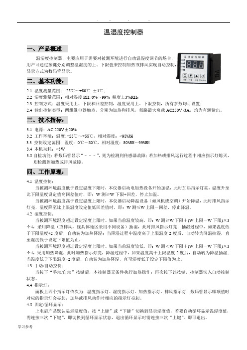
温湿度控制器一、产品概述温湿度控制器,主要应用于需要对被测环境进行自动温湿度调节的场合,用户可通过按键分别调整温湿度的上、下限值来控制加热或排风实现自动控制,显示方式为数码管显示。
二、基本功能:2.1 温度测量范围:-25℃~+80℃±1℃;2.2 湿度测量范围:相对湿度RH: 0%~99% 精度±3%RH;2.3 控制方式:温度采用上、下限和回差控制,湿度采用上、下限控制,所有参数均可设置;2.4 输出控制类型:两组继电器触点,分别为加热和排风,每路最大负载AC250V /3A,均为有源输出。
三、技术指标:3.1电源:AC 220V±20%3.2 工作环境:温度:-25℃~+55℃,相对湿度:<95%RH3.3控制设定范围:温度:0℃~80℃,相对湿度:50%RH~99%RH3.4 本机功耗:<3W3.5自检功能:若数码管显示“–––”,则为检测到传感器故障;若加热或排风运行过程中相应指示灯熄灭,则检测到加热或排风故障。
四、工作原理:4.1 温度控制:当被测环境温度低于设定温度下限时,本仪器启动电加热设备开始加温,此时加热指示灯亮,温度升至比下限温度设定值高回差值时,即:W测≥W下限+回差,停止加温。
当被测环境温度高于设定温度上限时,本仪器启动降温设备(如风机或空调)开始降温,此时排风指示灯亮,温度降至比上限温度设定值低回差值时,即:W测≤W上限-回差,停止降温。
4.2 湿度控制:当被测环境湿度超过设定湿度上限时。
如果当前温度较高,即:W测≥W下限+(W上限-W下限)×3÷4,采用降温(或排风,视具体地区采用不同设备)抽湿,此时排风指示灯亮;抽湿过程中,如果温度低于下限温度+2度后,自动转为加热降湿;当降湿过程中温度高于上限温度-2度后,自动转为降温抽湿,直至湿度低于设定下限值为止。
当被测环境湿度超过设定湿度上限时。
如果当前温度较低,即:W测<W下限+(W上限-W下限)×3÷4,采用加热降湿,此时加热指示灯亮,降湿过程中,如果温度高于上限温度-2度后,自动转为降温抽湿;当温度低于下限温度+2度后,自动转为加热降湿,直至湿度低于设定下限值为止。
温控管系列所有者教程 PandaWave射流 27801A01 复刻 00 12-2015说明书

Heat TraceInstallation InstructionsPA27801A01 Rev. 00 12-2015Using ST2MT or ST4MT Installation Tools© Panduit Corp. 2015Safety glasses must be worn at all times by all persons within ten (10) feet of working metal tie installation tool. CAUTION: Be aware of the ejection of metal cable tie scrap from tool.Safety gloves must be worn while applying metal ties using this tool.DO NOT use tool on live electrical sources.DO NOT place fingers near gripper during tool actuation. Fingers may be pinched by moving gripper.1. Determine minimum acceptable required length for Heat Trace Wave-Ty• Nominal pipe diameters are based on either inside diameter (ID) or outside diameter (OD); and thereare a number of schedules available throughout the internet.• ID is used for pipes sized from 0 – 12 inches. Greater than 12 inch pipe is typically measured in termsof OD.• The Panduit Heat Trace Wave Ty can cover pipes ranging from 1 inch up to 36 inches. 2. Use look up table for pipe diameters and Heat Trace Wave Ty part numbers.HTMLT TiePipe DiameterPart Number Width (in.) Length (in.)ST2MT/ST4MT ToolsStd. Pkg. Qty. HTMLT2.7WEH-LP 0.50 10.2 1.0 50 HTMLT4WEH-LP 0.50 14.3 2.0 50 HTMLT6WEH-LP 0.50 20.5 3.0, 4.0 50 HTMLT8WEH-LP 0.50 26.8 6.0 50 HTMLT10WEH-LP 0.50 33.0 7.0, 8.0 50 HTMLT12WEH-Q 0.50 42.2 9.0, 10.0 25 HTMLT16WEH-Q 0.50 54.8 11.0, 12.0, 14.0 25 HTMLT26WEH-Q 0.50 86.2 16.0, 20.0, 24.0 25 HTMLT38WEH-Q0.50123.926.0 - 36.025If you have a pipe diameter that is not listed on the table, move to the next highest size;, i.e., 5 inch pipe diameter. This would require the use of the HTMLT8WEH-LP for the ST2MT/ST4MT tool 3. Once you have selected the right size Heat Trace Wave Ty, go to actual onsite installation. For purposes of installing heat trace, first position heat trace against the pipe.© Panduit Corp. 2015INSTALLATION INSTRUCTIONSHEAT TRACEWITH ST2MT & ST4MT4.Once positioned in place, wrap HTMLT tie around pipe and heat trace every 12 inches. Feed the tail into the head of the wave ty and manual position and tighten. Do not position head of tie over the heat trace.5. Use recommended tool for Heat Trace application (either RT2HT, ST2MT or ST4MT). Once HTMLT tie is positioned and hand tightened around pipe and heat trace, begin feeding tail through side entry head of tool.6.Once tail is positioned through head of tool, begin squeezing handleto begin tightening HTMLT tie. As you tighten Heat Trace Wave Ty, you should begin to notice that heat trace is getting pulled in contact with the pipe. Repeat squeezing motion with handle until heat trace is tight and secure against pipe.7.Do not over tighten HTMLT ties. As tie begins to tighten around pipe, you may begin to notice that wave begins to flatten out. Be sure to stop tightening tie prior to wave becoming flat.8.Once heat trace is in contact with pipe and is tight and secure, move cutting handle upward to engage cutting action on the ST4MT and remove excess material. For the ST2MT keep tool engaged and twist counter clockwise (turn to the right) to cut off excess material.9.Repeat every 12 inches until heat trace is completely attached along the entire length of the pipe.U.S.A. Email:***********************U.S.A. Technical Support: Tel: 1-800-777-3300EU Website: /emea Email:*********************************Panduit Europe • EMEA Service Center Tel: +31-546-580-452 • Fax: +31-546-580-441 Latin America Website: Email::*****************Latin America:Tel: 52 (333) 666-2501 • Fax: 52 (333) 666-2510Asia/PacificEmail:*****************Asia/Pacific:Tel: 65 6379 6700 • Fax: 65 6379 6759。
简易型数显PID温控器 AT48 72 49 96B系列 说明书

简易型数显P I D温控器A T 48/72/49/96B系列使用说明书感谢您购买我们的温控器,使用之前请仔细阅读该说明书以充分了解其操作及性能。
R 继电器输出S SSR固态继电器输出空白 分辨率1℃/ F D 分辨率0.1℃/ F0 无任何报警输出1 1个继电器报警触点2 2个继电器报警触点AT48B W48×H48mm B系列电源电压主输出分辨率报警输出面板尺寸及系列①PV:显示值②SV:设定值③OUT:主输出指示灯④AL1:报警1 指示灯⑤AL2:报警2指示灯⑥SET:功能/确认键⑦AT/ :自整定/位移键⑧ :加键⑨:减键①②③④⑤⑥⑦⑧⑨* 注:本公司还有高性能A系列,经济型C系列。
* 注:AT49/72/96B均同于AT48BAT48B主输出主输出主输出传感器继电器热电阻热电偶SSR传感器报警输出电源电源电源1个报警继电器继电器热电阻热电阻2个报警SSRSSR热电偶热电偶AT49B W48×H96mm B系列AT72B W72×H72mm B系列AT96B W96×H96mm B系列4 100~240VAC 50/60HZ 2 DC24V目录一、型号选择二、面板标准及功能三、仪表接线图五、简易操作说明六、参数设置流程图四、主要技术参数1、型号选择2、面板标注及功能3、仪表接线图4、主要技术参数5、简易操作说明6、参数设置流程图7、参数设置文字描述8、注意事项AT48B14RDSETATA T48BNO NONONOCOMNC NC NC COMCOM COM 100~240V AC100~240V AC100~240V ACAL1AL1A AAB B B BBB 系列尺寸面板及深度开孔(mm)热电阻热电阻字符7段LED指示,4位数0.3%FS()+1×实际测量值个显示值ON/OFF AP1D O~200℃可调加热/致冷控制;无;个;个;0~200℃可调12-200~+4000.5秒可设定0~40倍(0~20S)约3W ≥2300VDCIEC6100-4-5 ±4KV/5KHZ -10~60℃; <90%RH℃可调100~240VAC 24VDC/AC 90~110%50/60HZ、;、继电器:,固态继电器:12V,30m A250V 2A后缀不带D为1℃;后缀带D为0.1℃分辨率指示精度输出类型控制方式输出滞后控制作用报警个数报警滞后输入信号显示主输出报警输出电源电压输入误差修正取样周期数字滤波消耗功率隔离耐压电磁兼容环境参数AT48BK .E .J .N .S .R Pt 10048×48×100W×H×L(mm)45×4568×6845×9292×9272×72×10048×96×10096×96×100AT72BAT49BAT96BVV++--AL2NONO NCNCCOMCOM 在运行状态下按 键可进入一级参数,按 等键可修改参数值,按一下键可进入下一个参数,到了参数“L O C”把数值改成808才能进入二级参数,否则返回运行状态。
可程式恒温恒湿控制器说明书

恒温恒湿控制器操作手册可程式恒温恒湿控制器1.机型号:TEMI8802.温度范围:-40~151500℃.%RH-98%RH3.湿度范围:2020%%-984.控制精度:±0.0.11℃;±1%RH5.电源:AC220V6.开孔尺寸:173173××133cm7.外观尺寸:183.5×143.5×112.7cm目录 (11)1.使用说明书···································································································································1.1设定按钮······································································································································· (11)1.1.1基本设定按钮 (1)1.1.2设定值输入键盘 (1)1.1.3设定按钮及设定值的有效性 (2) (22)1.2设定值输入方法···························································································································1.2.1设定值输入键的功能与说明 (2) (33)1.3基本运行设定流程图··················································································································· (44)1.4主画面···········································································································································1.5运行画面······································································································································· (55)1.5.1程式停止画面 (5)1.5.2程式运行画面 (7)1.5.3定值停止画面 (9)1.5.4定值运行画面 (10)1.5.5监视曲线画面 (11) (1212)1.6操作设定画面····························································································································· (1313)1.7预约设定画面····························································································································· (1313)1.8程式曲线画面····························································································································· (1414)1.9程式设定画面·····························································································································1.9.1程式(PATTERN)编辑画面 (15)1.9.2循环设定画面 (18)1.9.3程式管理画面 (21)1.9.4讯控设定画面 (22)1.9.5待机设定画面 (24)1.9.6程式名称设定画面 (26) (2727)1.10厂家资料画面···························································································································1.使用说明书1.1设定按钮▶该产品采用触摸屏输入方式,是一款客户使用操作非常方便的恒温恒湿可编程控制器。
TB系列温控器操作手册说明书

微電腦程序控制器操作手冊TB100 TB600 TB700 TB400 TB900在使用本控制器之前,請先確定控制器的輸入輸出範圍和輸入輸出種類與您的需求是相符的。
1. 面板說明1.1 七段顯示器PV :處理值(process value),紅色4位顯示 SV :設定值(setting value),綠色4位顯示.21.2 LED LED LEDOUT1 :第一組輸出(Output1),綠色燈OUT2 :第二組輸出(Output2),綠色燈 AT :自動演算(Auto Tuning),黃色燈PRO :程式執行中(Program),黃色燈 ----- 只適用於 P TB 系列 AL1 :第一組警報(Alarm 1),紅色燈 AL2 :第二組警報(Alarm 2),紅色燈MAN :輸出百分比手動調整(Manual),黃色燈※注意:當發生錯誤(Error)時,MAN 燈會亮,並將輸出百分比歸零1.3 按鍵SET:設定鍵(寫入設定值或切換模式) :移位鍵(移動設定位數):增加鍵(設定值減1):減少鍵(設定值加1) A/M :自動(Auto)/手動(Manual)切換鍵。
自動:輸出百分比由控制器內部演算決定手動:輸出百分比由手動調整OUTL(在User Level 中)決定2 自動演算功能(Auto tuning)2.2 需先將AT(在User Level 中)設定為YES ,啟動自動演算功能。
2.3自動演算結束後,控制器內部會自動產生一組新的PID 參數取代原有的PID 參數。
* 自動演算適用於控溫不準時,由控制器自行調整PID 參數。
2.4 ATVL:自動演算偏移量(AutoTuning offset Value)SV減ATVL為自動演算設定點,設定ATVL可以避免自動演算時,因PV值震盪而超過設定點(Overshoot)。
例如:SV=200℃,ATVL=5,則自動演算設定點為195℃當自動演算中,PV值震盪,則是在195℃上下震盪,因此可避免PV值震盪超過200℃。
温湿度控制器说明书

030温湿度控制器安装使用说明书V2.0申明版权所有,未经本公司之书面许可,此手册中任何段落,章节内容均不得被摘抄、拷贝或以任何形式复制、传播,否则一切后果由违者自负。
本公司保留一切法律权利。
本公司保留对手册所描述之产品规格进行修改的权利,恕不另行通知。
订货前,请垂询当地代理商以获悉本产品的最新规格。
江苏安科瑞电器制造有限公司吴磊磊提供135********目录前言 (1)1概述 (1)2工作原理 (1)一WH系列普通型温湿度控制器 (1)1型号说明 (1)2技术指标 (2)3产品规格及功能 (2)4接线方式 (4)二WHD系列智能型温湿度控制器 (5)1型号说明 (5)2技术指标 (5)3产品规格及功能 (6)4接线方式 (6)5产品操作指南 (8)6通讯指南 (11)三传感器 (15)1概述 (15)2型号说明 (15)前言:温湿度控制器简介1概述温湿度控制器产品主要用于中高压开关柜、端子箱、环网柜、箱变等设备内部温度和湿度的调节控制。
可有效防止因低温、高温造成的设备故障以及受潮或结露引起的爬电、闪络事故的发生。
产品分为WH普通型系列和WHD智能型系列。
产品符合国标GB/T15309-1994。
2工作原理温湿度控制器主要由传感器、控制器、加热器(或风扇等)三部分组成,其工作原理如下图所示:传感器检测箱内温湿度信息,并传递到控制器由控制器分析处理:当箱内的温度、湿度达到或超过预先设定的值时,控制器中的继电器触点闭合,加热器(或风扇)接通电源开始工作,对箱内进行加热或鼓风等;一段时间后,箱内温度或湿度远离设定值,控制器中的继电器触点断开,加热或鼓风停止。
除基本功能外不同型号还带有断线报警输出、变送输出、通信、强制加热鼓风等辅助功能。
一.WH系列普通型温湿度控制器1型号说明注:1.“组合外接”即同时有温度、湿度控制时,传感器置于同一外壳,由同一点采集温度、湿度信息。
2.传感器与控制器之间的连接线长度建议不要超过20米。
zbbwpks-p温控仪说明书

zbbwpks-p温控仪说明书在安装、操作和运行本温控器前,请仔细阅读本说明书,并妥善保管。
本温控器有危险电压,并监控电力变压器,如果不按照本说明书的规定操作可能会导致财产损失或人员严重受伤甚至死亡。
只有合格的技术人员才允许操作本温控器,在进行操作之前,要熟悉说明书中所有安全说明、安装、操作和维护规程。
本温控器的正常运行取决于正确的运输、安装、操作和维护。
1、温控器是电子计量产品,其使用寿命为五年,每年需进行周期检验。
2、本温控器只能按照本公司规定的目的和方法使用。
未经授权的修改和使用非本公司所出售或推荐的零配件都有可能导致本系统出现故障,甚至损坏。
3、使用前请您详细阅读该说明书。
设计部门的工作人员请重点参阅性能指标、外形尺寸、机械安装及电气连接;安装人员请重点参阅外形尺寸、机械安装、电气连接及异常现象处理;使用人员请重点参阅基本操作及异常现象处理。
4、每台温控器在使用前应进行功能测试,以保证使用的可靠性及测量、控制的精度。
5、温控器在运输时应采用原包装,以免造成机械损坏。
6、温控器不使用时,请进行防潮处理。
7、温控器使用时应注意电源等级(无特殊说明时,一般为AC220V)。
8、当您准备使用温控器时,请仔细阅读该说明书的电气连接部分,确认连接无误后再给温控器送电!9、为保证温控器输入信号质量,温控器正常运行前务必拧紧传感器插头。
10、在干式变压器进行耐压测试前,必须将传感器插头与温控器分离,以避免温控器被损坏。
11、切勿用打火机等明火对传感器探头进行模拟温升试验,否则会损坏Pt100传感器。
12、避免在含有二氧化硫(SO2)或其他腐蚀性气体的环境中使用本温控器,否则会使继电器的触点失效。
om温控器属于电子精密仪表,请客户妥善保管和放置,如确有问题,本说明书上或温控器面膜上有我公司的服务电话,请客户与本公司联系,公司有专人负责处理,谢谢合作。
同时感谢您使用。
我公司的温控器产品,不足之处请您提出宝贵意见。
P系列温度控制器程序控制操作说明(.

手動跳段: 程序執行中若欲改變目前執行段,先按住 鍵不放再按 一下 SET鍵。段數往前進一段,若遇到最後一段,將折返 起始段,且循環次數 SET鍵結束。
鍵 啟 動 目 前 段S V的 設 定 , 再 按
tr 0 第0段加溫時間。
10
範 圍: 0 ~ 6 0 0 0分。
Ho 0 第0段輸出量限值。 範 圍: 0 ~ 1 0 0 . 0 %。
100.0%
第1段~第15段參數與上敘相同在此省略。 不 在 區 間內 的 段 參 數(s t r t ~ en d),設 定 時 自 動 遮 罩以 節 省規畫時間。
2. 由於溫控曲線屬於直線型(RAMP),容易受積分項控 制影響造成過衝。如果過衝嚴重可將積分時間加長, 或 減 小 該 段 的H o參 數(最 大 量 限 制)。
3 .若W A I T >0,P V值 必 須 到 達 區 間 內 才 算 段 結 束 (SV-WAIT) ~(SV+WAIT)。
4 .若 欲 使 用A L M作 為 段 結 束 警 報 , 請 將 該 組 警 報 的 功 能 碼 設 為2 6, 例 如 想 要 第3段 結 束 時 警 報 輸 出 , 則 A L M數 值 請 設 定4, 若 要 第5段 結 束 時 輸 出 , 則 設 定 6。 依 此 類 推 。
顯示字節
文字
說明
AL 1 警報1設定,範圍:-1999~9999。
內定值
0
i 0.0 AL 2
HBA警報(選購),設定負載電流,若 選購此功能則無AL 1功能。 範 圍: 0 ~ 9 9 . 9。
警報2設定(選購) 範 圍: - 1 9 9 9 ~ 9 9 9 9。
0 . 0 (安 培) 0
电子温控器使用说明_电子温控器的调节方法
电子温控器使用说明_电子温控器的调节方法温控器,是指根据工作环境的温度变化,在开关内部发生物理形变,从而产生某些特殊效应,产生导通或者断开动作的一系列自动控制元件,也叫温控开关、温度保护器、温度控制器,简称温控器。
或是通过温度保护器将温度传到温度控制器,温度控制器发出开关命令,从而控制设备的运行以达到理想的温度及节能效果。
温控器应用范围非常广泛,根据不同种类的温控器应用在家电、电机、制冷或制热等众多产品中。
电子温控器使用说明液晶控温器,从字面上来看就是带有液晶屏的控温器。
液晶的控制器比较受人喜欢,因为可以清楚看到温度。
使用说明书对于消费者来说是起到一个引导说明的作用,对于消费者来说是非常有帮助的。
很多时候买的东西不一定会使用,就得靠着说明书。
那么说到液晶控温器,而液晶控温器使用说明书是怎样的呢?你对液晶温控器的了解有多少?液晶温控器是指配有液晶显示的温控器,主要特点是能够显示设定温度和室温等信息,操作方便等特点。
温控器使用说明书的重要性能够给予用户准确、明晰、简介的使用指导和说明,能够在一定程度上提高软件对于用户的亲和度和用户使用体验。
一个好的用户手册应该像一本工具书,能够在用户出现使用问题的时候迅速准确地找到解决方式。
(1)温控器的功能开/关控制室内温度设定时钟功能(可选)室内温度测量并显示睡眠功能(可选)手动或自动转换风机三速遥控功能(可选)冷/热转换控制蓝色背光(可选)多时段定时开/关机功能(可选)(2)温控器的特点温控器由单片机对其测量温度与设定温度进行比较,控制中央空调末端的风机盘管、电动阀、电动风阀、电动风口,使所控环境温度恒定为设定温度,以达到提高环境舒适度的。
温控器使用说明书
一周编程电子智能室内温控器LOGIC 578001使用指南引言感谢您选择了我们的产品及对我们的信任与支持。
本装置是电子式定时恒温器,可设置一星期为周期的运行程序。
通过该装置,可对安装环境内的温度进行十分精确的调节控制,满足用户对创造一个舒适生活环境的要求。
符合标准:符合欧盟法令:EN 60730-1 标准及其修订内容欧盟B.T.73/23/EEC号法令EN 60730-2-7 标准欧盟 E.M.C.89/336/EEC号法令及93/68/EEC修改法令EN 60730-2-9 标准产品规格:电源:二节LR6型1.5V碱性电池温度调节范围:10至35℃显示屏显示之环境温度:0至40℃(分辩率0.1℃)温度修正频率:每分钟一次微分:0.2至0.4K探针传感器:NTC3%保护等级:IP20绝缘等级:热梯度:1K/15分输出:转换继电器触点容量:8(2.5)A250V~作用类型:1BU绝缘条件:正常环境最大工作温度:50℃储存温度:0-60℃防冻温度:6℃恒定运行程序:以一星期为周期设置软件等级:A液晶显示屏夏季/冬季(采暖/空调)切换程序设置中的最小增减允许时间:1小时安装:壁式安装安装及连接:安全预防措施在进行定时恒温器的连接之前,请确认受其控制的设备系统(采暖锅炉、泵和空调系统等)电源已断开,并需检查这些设备的使用电压是否与定时恒温器底座上表明的电压相符(最大250V~).(图4)安装位置定时恒温器须安装在远离热源(暖气装置、阳光、厨房)和门窗之处,安装高度离地面约1.5米。
(图5)安装见图6-7-8电气连接将受定时恒温器控制的设备系统电线与定时恒温器的1号及2号接线柱连接见接线图10所示U=受定时恒温器控制的设备1=共用接线柱2=常开接线柱3=常闭接线柱重要事项:请务必严格遵照相关现行法律的规定及安全规范安装定时恒温器。
电池更换:当在显示屏上闪烁显示“”标志时,定时恒温器还可正常工作约一个月左右,然后将会停止工作并固定显示“”。
H12012 P-61温控器说明书

ߜPID orON/OFF ControlߜHeating and Cooling ߜOne Shot Tuner with Overshoot Inhibition ߜSetpoint Rate Limit ߜUniversalTemperature InputߜScalable LinearProcess InputߜNEMA-4X (IP65)Front PanelߜControl OutputsConfigurable asReverse/Direct Action ߜMultiple AlarmsConfigured ona Single OutputߜRS-232, RS-422,Modbus RS-485CommunicationsߜPDLINK Mode 1 Load Diagnostics withOptional SSC-TE10SContactor and dcPulse OutputߜOptional Ramp & Soak Profiler FeatureߜOptional ValvePositioner ControlThe CN2416 is a versatile, high stability temperature or process controller, with self and adaptive tuning, in a 1⁄16DIN size. It has modular hardware construction which will accept up to threeplug-in I/O modules and one communications module. Precise ControlAn advanced PID control algorithm gives stable control of the process.A one-shot tuner is provided to set up the initial PID values and tocalculate the overshoot inhibitionparameters.In addition, an adaptive tuner willhandle processes with continuallychanging characteristics. Powerfeedback employs power controltechniques which stabilize thecontrolled temperature against supplyvoltage fluctuations on electricallyheated loads. Dedicated coolingalgorithms ensure optimum control offan, water and oil cooled systems.Universal InputA universal input circuit withan advanced analog-to-digitalconverter samples the input at9 Hz and continuously correctsit for drift. This gives high stabilityand rapid response to processchanges. High noise immunity isachieved by rejection of 50/60 Hzpick-up and other sources of noise.Sensor diagnostics are alsoprovided. The input covers allthermocouple types, Pt100 RTDand linear millivolt, milliamps or dcVoltage. Input filtering from OFF to999.9 seconds is standard.Customized OperationCustom LED’s provide a bright,clear display of the process value andsetpoint. Front panel auto/manualbutton is provided.PDLINK Mode 1 LoadDiagnostics (PDL1)PDLINK is a major innovation inthe CN2416. When used incombination with an OMEGA®SSC-TE10S solid state contactor,it allows the dc pulse output of aCN2416 to transmit the powerdemand signal and simultaneouslyread back a load fault alarm onthe same pair of wires. This alarm willflash as a message on the controllerfront panel and cantrip the alarm relay. It indicatesthat there is a fault in the heatingcircuit caused by either fuse failure,SSC open or short circuit, heater opencircuit or the absenceof line supply.Digital CommunicationsThe CN2416 is available withRS-232, four-wire RS-422/485 andtwo-wire RS-485 communications.Model CN2416Shown actual sizeCN2100, CN2200 & CN2400 Family1⁄16DIN Sophisticated Optional Profiler, Valve PositionerControl and CommunicationsCN2416 Series$344Basic UnitProgramP-61P-62Specifications InputGeneral:Range:±100mV and 0 to 10 Vdc (auto ranging)Sample Rate:9 Hz (110 ms)Calibration Accuracy:0.2% of reading, ±1 LSD, ±1°C/FResolution:<1 µV for ±100 mV range, <0.2 mV for 10 Vdc range Linearization Accuracy:No discernable error Zero Drift with AmbientTemperature:<1 µV per °C for ±100 mV range, 0.1 mV per °C on 10 Vdc rangeGain Drift with Ambient Temperature:<0.004% of reading per °CInput Filter:OFF to 999.9 secs Zero and Span Offset:Useradjustable over the full display rangeThermocoupleTypes:Refer to sensor inputs and display ranges tableCold Junction Compensation:Automatic compensation typically >30 to 1 rejection of ambient temperature change. Internal or selectable for external references of 0, 45 and 50°C (32, 113 and 122°F)RTD/Pt100Type:3-wire, Pt100 DIN43760 Lead Compensation:No error for up to 22 ohms in all 3 leadsProcessRange:±100 mV, 0 to 20 mA or 0 to 10 Vdc (all configurable between limits)Type:Linear, square root or custom 8 pointOutputsRelay:Rating: SPST, Min: 12 Vac/dc,100 mA Max: 2 A, 264 Vac/dc resistive Application: Heating, cooling, or alarms dc Pulse:Rating: 18 Vdc at 24 mA (non-isolated)Application: Heating, cooling or alarms PDLINK Mode 1:Logic heating with load failure alarm ac SSR:Rating: 1 A, 30 to 264 Vac resistive Application:Heating or cooling Analog:Range: Non-isolated,0 to 20 mA (into 600 Ωmax) 0 to 10 Vdc (both configurablebetween limits) Application: Heating,cooling or process outputDisplay:Dual, 4-digit x 7-segment high intensity LED Dimensions:48 W x 48H x 150 mm D (1.89 x 1.89 x 5.91")Temperature and RH:Operating: 0 to 55°C (32 to 131°F),RH: 5 to 90% non-condensing. Storage: -10 to 70°C (14 to 158°F)Panel Sealing:NEMA-4X, IP 65Electromagnetic compatibility:Meets generic emissions standard EN50081-2 for industrial environments Meets general immunityrequirements of EN50082-2 for industrial environmentsSafety Standards:EN61010,installation category 2 (voltage transients must not exceed 2.5 kV)Atmospheres:Electrically conductive pollution must beexcluded from the cabinet in which this controller is mounted. Thisproduct is not suitable for use above 2000 m (6,562 ft) or in corrosive or explosive atmospheres without additional protection.Weight: 250 g (8.82 oz)Model CN2416Sensor Inputs and Display RangesDepartment for details. ** When used with 2.49 Ωshunt resistor.CommunicationsDigitalTransmission Standard: RS-232,RS-422, RS-485 at 1200, 2400,4800, 9600, 19,200 baud Protocols: MODBUSControl FunctionsControlModes: PID or PI with overshoot inhibition, PD, PI, P only or On/Off Application: Heating or cooling Auto/manual: Bumpless transfer or forced manual outputSetpoint Rate Limit:0.01 to 99.99degrees or display units per second,minute or hour. Display setpoint rate limit is the same as the display resolution.Cooling Algorithms:Linear; Water (non-linear); Fan (minimum on time); Oil, proportional only TuningOne-Shot Tune: Automaticcalculation of PID and overshoot inhibition parametersAdaptive Tune: Continuous assessment of the PID values Automatic Droop Compensation:Automatic calculation of manual reset value when using PD control AlarmsTypes: Full scale high or low.Deviation high, low, or band. Rate of changeModes: Latching or non-latching.Normal or blocking actionUp to four process alarms can be combined onto a single outputGeneralSupply:85 to 264 Vac, 48 to 62 Hz 10 watts max5.91 in (150 mm)Panel cut-out (45 mm x 45 mm)1.77" x 1.77"1.89 in (48 mm)OP1OP2SP2REM1.89 i n (48 m m )CN2416 Dimensionsof Relay output module Field Installable Output and Communications ModulesTwo-wire RS-485 communicationsCANADA www.omega.ca Laval(Quebec) 1-800-TC-OMEGA UNITED KINGDOM www. Manchester, England0800-488-488GERMANY www.omega.deDeckenpfronn, Germany************FRANCE www.omega.frGuyancourt, France088-466-342BENELUX www.omega.nl Amstelveen, NL 0800-099-33-44UNITED STATES 1-800-TC-OMEGA Stamford, CT.CZECH REPUBLIC www.omegaeng.cz Karviná, Czech Republic596-311-899TemperatureCalibrators, Connectors, General Test and MeasurementInstruments, Glass Bulb Thermometers, Handheld Instruments for Temperature Measurement, Ice Point References,Indicating Labels, Crayons, Cements and Lacquers, Infrared Temperature Measurement Instruments, Recorders Relative Humidity Measurement Instruments, RTD Probes, Elements and Assemblies, Temperature & Process Meters, Timers and Counters, Temperature and Process Controllers and Power Switching Devices, Thermistor Elements, Probes andAssemblies,Thermocouples Thermowells and Head and Well Assemblies, Transmitters, WirePressure, Strain and ForceDisplacement Transducers, Dynamic Measurement Force Sensors, Instrumentation for Pressure and Strain Measurements, Load Cells, Pressure Gauges, PressureReference Section, Pressure Switches, Pressure Transducers, Proximity Transducers, Regulators,Strain Gages, Torque Transducers, ValvespH and ConductivityConductivity Instrumentation, Dissolved OxygenInstrumentation, Environmental Instrumentation, pH Electrodes and Instruments, Water and Soil Analysis InstrumentationHeatersBand Heaters, Cartridge Heaters, Circulation Heaters, Comfort Heaters, Controllers, Meters and SwitchingDevices, Flexible Heaters, General Test and Measurement Instruments, Heater Hook-up Wire, Heating Cable Systems, Immersion Heaters, Process Air and Duct, Heaters, Radiant Heaters, Strip Heaters, Tubular HeatersFlow and LevelAir Velocity Indicators, Doppler Flowmeters, LevelMeasurement, Magnetic Flowmeters, Mass Flowmeters,Pitot Tubes, Pumps, Rotameters, Turbine and Paddle Wheel Flowmeters, Ultrasonic Flowmeters, Valves, Variable Area Flowmeters, Vortex Shedding FlowmetersData AcquisitionAuto-Dialers and Alarm Monitoring Systems, Communication Products and Converters, Data Acquisition and Analysis Software, Data LoggersPlug-in Cards, Signal Conditioners, USB, RS232, RS485 and Parallel Port Data Acquisition Systems, Wireless Transmitters and Receivers。
PmodTMP2 温度传感器和温控板说明书
410-221P m o d T M P 2™ R e f e r e n c e M a n u a lRevision: October 11, 20111300 NE Henley Court, Suite 3Pullman, WA 99163(509) 334 6306 Voice | (509) 334 6300 FaxDoc: 502-221page 1 of 2OverviewThe PmodTMP2 is a temperature sensor and thermostat control board built around the Analog Devices ADT7420.Features include:• Up to 16-bit resolution• Typical accuracy better than 0.25 °C • I 2C interface with 4 selectableaddresses• 240ms continuous conversion time • Support for 3.3v and 5v interfaces • No calibration required • Programmableovertemperature/undertemperature control pins.Functional DescriptionThe PmodTMP2 uses an 8-pin connector that allows for communication via I 2C, and provides pins to daisy-chain the PmodTMP2 to other I 2C devices. The PmodTMP2 also provides two 2-pin headers for selecting the I 2C address of the chip, and two 2-pin headers for controlling external devices based upon temperature thresholds defined by the user in software.I 2C InterfaceThe PmodTMP2’s onboard ADT7420 chip acts as a slave device using the industry standard I 2C communication scheme. To communicate with the PmodTMP2 device the I 2C master device must specify a slave address (0x48-0x4B) and a flag indicating whether thecommunication is a read (1) or a write (0). This is followed by the actual data transfer. For the ADT7420, the data transfer should consist of the address of the desired device register followed by the data to be written to thespecified register. To read from a register the master must write the desired register address to ADT7420, then send an I 2C restartcondition, and send a new read request to the ADT7420. If the master does not generate a restart condition prior to attempting the read, then the value written to the address register will be reset to 0x00.As some registers stored 16-bit values as 8-bit register pairs, the ADT7420 will automatically increment the address register of the device when accessing certain registers such as the temperature registers and the thresholdregisters. This allows for the master to use a single read or write request to access both the low and high bytes of these registers. Acomplete listing of registers and their behavior can be found in the ADT7420 datasheet available on the Analog Devices web site.The I 2C interface standard uses two signal lines. These are I 2C data and I 2C clock. These signals map to the serial data (SDA) and serial clock (SCL) respectively on the ADT7420.Connector J1 – I2C Communications Pin Signal Description 1, 2 SCL I2C Clock 3, 4 SDA I2C Data 5, 6 GND Power Supply Ground 7, 8 VCC Power Supply (3.3V/5V)PmodTMP2 Reference Manualpage 2 of 2I 2C Address SelectionThe PmodTMP2 I 2C bus can be set to use one of four valid addresses. The top five bits of the address are fixed, and the two least significant bits are taken from the jumper states of JP2 and JP1. JP2 corresponds to bit one of the address while JP1 corresponds to bit zero. An open jumper corresponds to a one in theaddress while a shorted jumper corresponds to a zero. For example, when JP2 and JP1 are open the device uses the address 0x4B (0b1001011).Open Drain OutputsThe PmodTMP2 provides two open drainoutput headers for controlling external devices based upon current temperature thresholds. If the temperature leaves a range defined by registers T LOW (0x06:0x07) and T HIGH(0x04:0x05) then the INT pin on J3 can be driven low or high based upon theconfiguration of the device. Similarly, the CT pin on J2 can be driven low or high if the temperature exceeds a critical thresholddefined in T CRIT (0x08:0x09). Both of these pins are pulled up by 10KOhm resistors when they are not driven by the device. For details on their electrical specifications and configuration of the INT and CT pins please refer to the ADT7420 datasheet.Quickstart OperationWhen the PmodTMP2 is powered up, the onboard ADT7420 is in a mode that can be used as a simple temperature sensor without any initial configuration. By default, the device address register points to the temperature MSB register, so a two byte read without specifying a register will read the value of the temperature register from the device. The first byte read back will be the most significant byte(MSB) of the temperature data, and the second will be the least significant byte (LSB) of the data. These two bytes form a two’scomplement 16-bit integer, if the result isshifted to the right three bits and multiplied by 0.0625 the resulting signed floating point value will be a temperature reading in degrees Celsius.For information on reading and writing to the other registers of the device, as well as notes on the accuracy of the temperaturemeasurements please refer to the ADT7420 datasheet.Addresses JP2 JP1 Address Open Open 0x4B (0b1001011) Open Shorted 0x4A (0b1001010) Shorted Open 0x49 (0b1001001) Shorted Shorted 0x48 (0b1001000)410-221。
温控表P控制器温控器安全操作及保养规程
温控表P控制器温控器安全操作及保养规程温控表 P 控制器温控器是一种重要的仪器设备,可用于自动控制温度。
若使用不当,可能会对人身安全和设备产生损害,因此,遵循操作规程是十分必要的。
安全操作规程1.在使用温控表P 控制器温控器前,请先仔细阅读用户手册,并确保已经了解了每一个功能键的功能和使用方法。
2.在使用温控表 P 控制器温控器时,请不要进行私自改装和修理。
如需要进行调整,请将设备送到专业维修机构处理。
3.当使用温控表 P 控制器温控器进行高温操作时,请时刻注意防火措施。
设备离开时,请务必关闭电源开关,确保设备熄火。
4.温控表 P 控制器温控器需放置在干燥、通风良好、不含腐蚀性气体的环境中使用,防止设备受到潮湿和腐蚀。
5.在更改温控表P 控制器温控器的设置参数时,请设置纯净、无杂质的水量来对温控器进行清洗。
保养规程1.请经常检查温控表 P 控制器温控器的电源线、接线端子和开关部分,确保其完整、干净、无磨损和锈蚀。
若发现有损坏现象,请立即更换。
2.温控表 P 控制器温控器应经常进行内部清洗。
请注意不要用水或其它液体来清洁设备内部,在处理设备内部时,请使用专业设备来进行清洗。
3.如果温控表 P 控制器温控器长时间不使用,则要将设备放置在干燥、通风良好、不含腐蚀性气体的环境条件下,同时定期进行维护保养。
注意事项:温控表P 控制器温控器为精密仪器,在使用过程中应注意以下事项:1.要根据用户手册的要求正确操作设备。
2.请勿放置在有潮湿,多尘和高温的地方。
3.存放设备时,请保持通风。
4.如长时间不使用,需进行定期维护保养选定的维护点。
以上是温控表 P 控制器温控器的安全操作及保养规程。
在使用设备时,请务必遵循以上规程,保证设备的长期稳定运行。
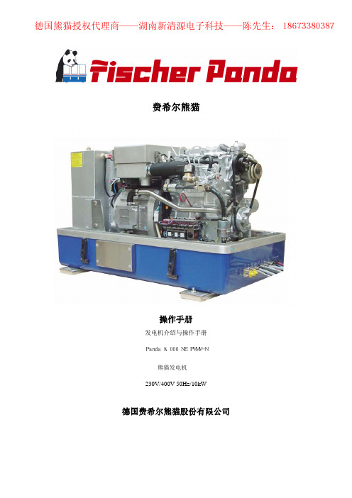
熊猫发电机使用指南
12
德国熊猫授权代理商——湖南新清源电子科技——陈先生:18673380387
维修说明
维修要求
开始前控制 油位 冷却系统泄漏 任何变化、泄漏排油系统、三角皮带、电缆连接、软管夹、空气过滤器和燃油管路的目
5
德国熊猫授权代理商——湖南新清源电子科技——陈先生:18673380387 前视图
1. 内部冷却水泵排气螺丝 2. 内部冷却水泵滑轮 3. 燃油电磁阀 4. 机油液位尺 5. 冷却水入口管 6. 燃油过滤器 7. 消音底座部分 8. 燃油进囗 9. 燃油出囗 10. 燃油泵线束(2X1.5mm2) 11. 远程控制面板线束(12X1m
11.起动机电磁开关 12 发动机法兰 13 连接冷却水入口(注: 内接氷泵) 14 配有绕组的发电机外壳 15 连接冷却水出口(外接散热器入囗) 16 连接排气软管 17 连接外部冷却水膨胀箱 18 配有干燥静音水冷消音器 19 通向膨胀箱的排气软管
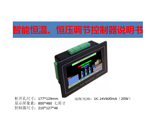
空调用恒温恒压控制器操作说明书
2.4参数设置—控制方式
压力模式下的控制方式界面
温度模式下的控制方式界面
泵组运行模式选项应用说明
* 通用变频运行模式 此模式下,系统增泵时,先以变频器启动水泵后,若在给定的时间内不能满 足设定需要,则本泵转为工频,然后变频器再启动下一台泵,依次循环;系 统停止时,会自动记住当前运行的泵号。下次启动时,系统将从下一台泵号 启动,从而使各泵工作时间均衡。 此模式适合15KW以下大多数变频恒压供水模式 * 全变频运行模式 此模式下,每台泵都需配置一台相应的变频器,启动与循环方式与上相同 * 变频泵循环,加泵时直接投入工频泵模式 此模式适合大功率泵组简单控制方式运行。配线时请注意,此模式下,循环 泵定时循环轮换使用(定时换泵时间不为零时),压力不够需加泵时,直接启动 工频泵运行,工频泵可通过软启或其它降压启动方式运转。注意:变频泵在 每启停一次,会转换到下一台首先运行,在设定的换泵时间到达时,系统会 停机,然后变频泵换到下一台重新运行。 * 工频运行模式 此模式为小功率泵全工频运行,运行时所配置的泵依次全部投入运行
2.2参数设置—传感器设置
根据现场所配传感器量程和信号方式,选择相符的设置,当 管网上显示压力与控制器显示有误差时,可通过改变修正值 使其相符
2.3参数设置—切泵条件
•此项菜单中,请注意变频器增减速时间的设置值,如果小于变频器中所设值,系统将 不能正常工作。现场调试时,要使变频器与控制器显示的频率同步。(通常可把变频 器中设置的加减速时间设小些) •变频转工频延时时间,理论上越小就越利于工频泵的启动。
时间日期设置
功能选择项:可以选择本控制器做为压力控制或 者温度控制使用! 出厂设置进入的密码
1.1 出厂设置—主界面右侧图形选择
右侧显示冷风塔
【精品】特灵空调使用手册
1导言1。
1范围本文描述的功能规格适用于odyssey主板及其同系列产品. 1。
2产品范围此空调控制器必须连线控器及其同系列产品一起使用。
1。
3产品特点a)制冷/除湿/制热/风扇/自动模式。
b)两级电加热功能。
c)具有断电记忆功能.d)具有遥控功能(可选).e)相互独立的双室外风扇。
f)电加热与热泵切换功能。
g)定时开/关机时间长达24小时。
i)机组压缩机再启动保护及分别启动延时。
j)机组压缩机协调工作功能。
k)机组压缩机高压保。
l)机组压缩机低压保护.n)机组压缩机过载保护。
q)制热模式下具有防止室内盘管过热功能。
r)制冷模式下具有防止室内盘管结冰功能。
s)双系统同时除霜及除霜代码显示功能。
t)感温器缺失自动检测功能。
u)故障代码显示。
v)来电自启动.x)回风及盘管温度显示功能。
2功能Tr=回风温度Ts=设定温度Toc=室外盘管温度Toet=室外环境温度Tic=室内盘管温度2。
1上电设置首次上电后,系统初始设置如下:室温(Tr)模式设定温度室内风扇≥25℃制冷25℃运行≤20℃制热20℃运行20℃<Tr<25℃风扇24℃运行这些设置仅仅适用于机组首次上电启动。
这是系统首次上电的缺省设置。
2.2系统拨码设置内机拨码:SWA1(模式选择)ON,为单冷;反之,为热泵SWA2(压缩机选择)ON,为单压缩机;反之,为双压缩机SWA3(电加热选择)ON,为带电加热;反之,为无电加热SWA4(来电自启动选择)ON,为来电自启动;反之,无来电自启动SWA5(除霜防冷风程序选择)ON,为除霜不停风机;反之,除霜停风机SWA6KFC电加热模式ON,为KFC模式;反之,普通模式外机拨码:SWB1备用SWB2备用线控器拨码:SWC1(房间温度探头切换)ON,为线控器温度;反之为回风温度。
SWC2辅热功能切换;ON为辅热键为热泵辅热切换键;反之辅热键为关闭开启辅热按键(仅热泵+电加热非KFC有效)2。
4开关有2种方法开关系统:i)通过ON/OFF开关触发ii)通过定时功能设定2。