XL4002最新中文版
Doble M4000软件版本4.1安装指南说明书

72A-3154-01 Rev. A 12/20091M4000 Version 4.1 Installation GuideThis document explains how to install the M4000 software version 4.1 on a laptop or the M4200C Controller.RequirementsLaptop requirements are as follows:•Operating system—Windows 2000 or newer •Web browser—Microsoft Internet Explorer V5.0 or newerThe M4200C Controller must run the M4200 Thermal printer driver as the default.To confirm that the M4200 Thermal driver is the default printer driver:1.Open the Start menu and select Control Panel .2.Select Printers and Other Hardware .3.Open View installed printers and fax printers .4.Confirm that M4200 Thermal is selected as the default (a black circle with a checkmark in it should appear next to the driver name in the list).•If it is not the default printer, highlight the M4200 Thermal printer icon, open File on the menu and select Set as Default Printer . •If the M4200 Thermal printer is not listed, please contact your Dobleprincipal engineer or local representative.Downloading M4000To download M4000 from the Doble web site:1.Go to .2.Open the Support menu and click Downloads .3.Click the M4000 link, and on the M4000 page, click the M4KV41.exe link.4.Click Save to save the file to your hard disk, or click Run to run Setup.exe immediately. Go to “Installing the Software” on page 2. 1981M4000 Version 4.1 Installation Guide272A-3154-01 Rev. A 12/2009Installing the SoftwareTo install M4100:1.Double-click the Setup.exe file.The Choose Setup Language window appears. It enables you to select thelanguage in which the remaining setup instructions will be presented.2.Select a language from the drop-down list and click OK.3.Read the Welcome advisory information and, if acceptable, click Next.4.Read the software license agreement and, if acceptable, click Yes.5.In the Choose Destination Location window:•Click Next to accept the default folder for the M4000 software.or•Browse to another folder and click Next.6.In the Select Program Folder window, choose a location for the M4000program icon and click Next.The Laptop/M4200 Controller Options window appears.7.Select these options as appropriate:•Launch M4000 at Startup—Automatically starts M4000 each time thePC or M4200 Controller is turned on.•Set the serial port to COM2 (default is COM1)—Select this option ifyou use an M4200 Controller, which always requires COM2.8.Click Next.The Safety Settings window appears. These settings are stored as Registryentries and can be changed by users through the Tools/Configurationmenu, unless access is restricted.Check marks appear in the options that are turned on by default.M4000 Version 4.1 Installation Guide72A-3154-01 Rev. A 12/200939.In the Safety Settings window, select the safety options as appropriate:•Beeper is enabled —Enables the warning beep that signals the beginning of each test (recommended).•Both LV Leads must be inserted to run test —Requires that both the red and blue leads be inserted into the test set to run a test (rarely used).•Safety strobe is required to run test —If the strobe bulb or cable fails, you can disable it so that you can continue testing. •Safety switch must be released between tests —Discourages users from artificially holding the safety switch down for the duration of several tests.•Restrict the Safety Configuration settings —Locks the above fourselections so that they cannot be changed from within the application.10.Click Next .The Auto-fill the Company Field window appears. Any name entered in this field automatically appears in the Company field whenever a new test form is created.11.Enter a name or leave the field blank. Click Next.M4000 Version 4.1 Installation Guide472A-3154-01 Rev. A 12/200912.In the M4000 Language Support window, select one or more languages forthe M4000 user interface. Click Next.The Choose the M4000 Data Directory window appears. This directory will store all results of tests run with the M4100 clipboard.13.Accept the default directory or browse to a different directory. Click Next.The Start Copying Files window appears. It summarizes the configuration options you have selected.14.If necessary, click Back to modify the setup options. Then click Next tostart file installation.The Copying Resource Files window appears and displays a progress bar.When the process is complete, the Setup Complete window appears. 15.As appropriate, select these options:•Yes, I want to view the ReadMe file.•Yes, I want to launch M4000.16.Click Finish.Running Multiple Versions of M4000You can run multiple versions of M4000 by installing them in differentdirectories. Be aware that whenever you switch from one version to another,M4000 prompts you to download new firmware. To prevent this prompt fromappearing:1.Locate the M4i.x0, BootBlok.x0, and Loader.x0 in the directoryin which version 3.4 or 4.0 is installed. The default directory isC:\Program Files\Doble\M4000.2.Copy these three files into the other M4000 directories.Updating the FirmwareThis section is for newer M4100 instruments only, with a serial number formatof four digits, a numeral one, and four more digits (xxxx1xxxx).IntroductionWhen M4000 is updated, new firmware is downloaded with it but notinstalled. The updated M4000 automatically checks the currently installedfirmware and, if appropriate, displays a message stating that new firmware isavailable. Immediate upgrade is not required; you can wait for a suitable time.M4000 Version 4.1 Installation Guide72A-3154-01 Rev. A 12/20095Time RequirementsThe firmware upgrade takes 25 to 30 minutes. The associated amplifier upgrade, which is sometimes required, takes an additional 15 minutes.Cable RequirementsThe USB cable supplied with the M4100 is required for this upgrade. You must manually install the USB driver for this cable.If the upgrade is attempted using a USB-to-RS232 adapter with the old serial cable, the upgrade will fail.Procedures for Firmware and Amplifier Firmware UpdateThe following procedures describe how to upgrade the firmware, and how to upgrade the amplifier (PUC) firmware if necessary.Read This First!As you begin upgrading, please keep the following information in mind:•Do not power cycle the M4100 during the upgrade. Power cyclingduring a firmware or amplifier firmware upgrade causes theM4100 to become unusable . You will have to ship the unit back toDoble for reconfiguration.•If M4000 is accidentally closed during an upgrade, power cycle theM4100 and start the upgrade over again.•Depending on the version of the firmware or amplifier firmware youare upgrading, an Error 101 message may appear after the upgradecompletes successfully. Close it and continue with the upgradeprocess.M4000 Version 4.1 Installation Guide672A-3154-01 Rev. A 12/2009Upgrading the FirmwareTo upgrade the firmware:1.Open the Tools menu and select Update the Firmware.A warning message appears.N OTE Do not power cycle the M4100 during the upgrade for any reason!If power cycling occurs, the M4100 becomes unusable and must be shipped back toDoble for reconfiguration.2.To start the upgrade, click Yes.Several progress bars appear during the upgrade.Depending on the version of the firmware being updated, an Error101message may appear after the upgrade is completed successfully.3.Click OK and power cycle the M4100.Upgrading the Amplifier (Power Unit Control)To determine if the Amplifier (PUC) firmware needs to be updated:1.Open the Diagnostic menu and select System Status.The M4000 - System Status Diagnostic window appears.2.Press F2 to run the test.When complete, the Reported Status for each item should be Enabled.3.Look at the M4100 Instrument Amplifier Version field. If it displays a:•Blank—The Amplifier/PUC cannot be upgraded in the field and unitmust be returned to Doble for upgrading.•Number—Go to step 4.M4000 Version 4.1 Installation Guide72A-3154-01 Rev. A 12/200974.Open the Tools menu and select Update the Amplifier Firmware .One of these messages appears:•Error 105—Indicates that the amplifier firmware cannot be upgradedin the field. Click OK and power cycle the M4100. You can continue to use the instrument while you make arrangements to ship it to Doble for upgrade.•Update the M4100 Amplifier Firmware N OTE Do not power cycle the M4100 during the upgrade for any reason! If powercycling occurs, the M4100 becomes unusable and must be shipped back to Doble for reconfiguration.5.To start the upgrade, click Yes .Several progress bars appear during the upgrade.Depending on the version of the firmware being updated, an Error 101 message may appear after the upgrade is completed successfully.6.Click OK and power cycle the M4100.7.Run another System Status test.The following data should appear:•M4100 Instrument Firmware Version: 3.4555•M4100 Instrument Amplifier Version: 1.31Reporting ProblemsPlease communicate any problems or enhancement requests to your Dobleprincipal engineer or local Doble representative.M4000 Version 4.1 Installation Guide872A-3154-01 Rev. A 12/2009。
最新505X中文版V.15程序安装与在线匹配设置

505X中文版V.15程序安装与在线匹配设置05/05 陈顺生05/05安装前的准备工作为保证安装过程的顺利,首先确保下列必要的硬件完好无损!诊断仪系统光盘基础光盘数据光盘5052A的介绍诊断仪USB连线诊断接口安装步骤1、安装系统光盘V.022、安装基础光盘V.15.00安装品牌光盘(V15V1501V1503)3、安装品牌光盘(V.15>> V.15.01>> V.15.03)4、安装UDS协议补丁程序5、诊断接头5054蓝牙的设置诊断接头6、更改计算机名7、设置IP地址8、在线授权设置一、安装系统光盘V.02将系统光盘V.02放入VAS 5052AVAS5052A的光驱,并重新启动WINDOWS后,VAS 5052A即通过光驱引导程序开始操作系统安装的安装。
1、重新启动windows后系统由光盘自动引导进入gghost 8.0回复界面回复系统。
2、系统恢复完成后,将自动进行重新启动。
自动重新启动后界面自动运行完毕后出现此界面自动运行完毕后出此面英文解释:系统安装完成英文解释系统安装完成英文解释:将光盘从光驱取出,关闭主机电源一、安装系统光盘V.02一定要取出光盘,然后再关闭电源一、安装系统光盘V.02系统启动完成后的界面重新开启电源开关,系统自动启动重新启电关系统自动启动一、安装系统光盘V.02等待一段时间后系统出现此界面选择“Yes”后系统自动再次重新启动后完成系统的安装过程。
重新启动完成后即可进行基础盘安装二、安装基础光盘V.15.00在windows界面下将基础盘V.15.00装入光驱中等待光驱自动执行程序后,会在Windows桌面上出现如下提示:选择“Install languageEnglish”,再选择“OK”选择Install language English后,进入如下界面:选择“Install VAS-PC”选择Install VAS-PC后,会出现如下界面:选择“Agree”选择Agree后,进入如下界面:选择“start Installation”选择start Installation,即会出现如下安装界面:安装过程中会出如下个提示安装过程中会出现如下一个提示:安装过程中会出现如下一个提示:选择“Finish”选择Finish,完成最终安装。
XLB-400使用说明书

青岛可耐达机械设备有限公司产品使用说明书目录一、安全注意事项-----------------------------------------------------2二、本机用途-----------------------------------------------------------4三、机器的结构--------------------------------------------------------4四、主要技术参数-----------------------------------------------------4五、机器的安装和试运转--------------------------------------------5六、机器的使用与保养-----------------------------------------------6七、易出现的故障及排除方法--------------------------------------6一、安全注意事项1. 一般信息装置运行过程中,其某些部件可能会带电,旋转或发热。
不正确的开盖,不当使用和安装均可能导致人员伤害或设备损坏。
详细信息可从有关文件中获取。
本设备的运输、安装、调试及维护必须由训练有素合格的人员完成。
合格人员指具有一定资格并熟悉本产品的安装、调试、操作的人员。
2.运输、储存机械设备能正常工作在预期使用环境温度5~40℃ ,相对湿度不超过90%,工作环境应通风良好并远离腐蚀性或易燃、易爆气体场所。
设备通过设计或采取保证能经受住-25 ℃~55℃的温度范围内的运输和存放、并能经受温度高达70℃、时间不超过24H的短期运输和存放。
应采取防潮、防震和抗冲击措施,以免损坏电气设备。
3. 起吊在吊装设备时,根据设备的重量选择合适的钢索和吊车起吊,不能通过一个支撑点起吊设备。
4. 电气连接温度控制装置在运行中应遵循有关防止事故发生的国家规则。
林肯电子下灵200 400操作手册说明书
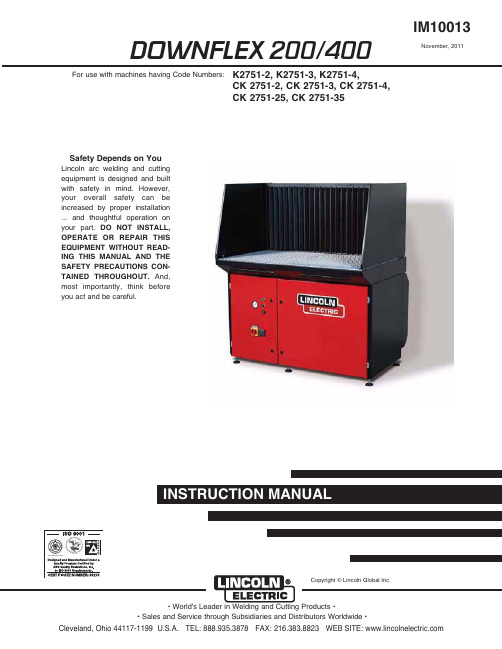
DOWNFLEX 200/400IM100131RYHPEHU , 2011Safety Depends on YouLincoln arc welding and cutting equipment is designed and built with safety in mind. H owever,your overall safety can be increased by proper installation ... and thoughtful operation on your part.DO NOT INSTALL,OPERATE OR REPAIR THIS EQUIPMENT WITHOUT READ-ING THIS MANUAL AND THE SAFETY PRECAUTIONS CON-TAINED THROUGHOUT.And,most importantly, think beforeyou act and be careful.For use with machines having Code Numbers:K2751-2, K2751-3, K2751-4,CK 2751-2, CK 2751-3, CK 2751-4,CK 2751-25, CK 2751-35Copyright © Lincoln Global Inc.vfor selecting a QUALITY product by Lincoln Electric. We want you to take pride in operating this Lincoln Electric Company product •••as much pride as we have in bringing this product to you!TECHNICAL SPECIFICATIONS - DOWNFLEX 200/400GENERAL DESCRIPTIONThe downdraft table is a workbench with an integrated extraction fan and filtration system that is used for welding, grinding and plasma cutting applications. Depending on the specific application, the use of cer-tain accessories is required and/or recommended. See Accessories section of this manual.The downdraft table features a work grid, a three-stage prefiltration system for optimum spark arresting and two oval main filter cartridges. Both pre and main filters have dust drawers underneath. The working height of the downdraft table is adjustable. The control panel contains a 120V power outlet for connection of any device, such as a vacuum cleaner or grinding machine (max. 1200W).INTENDED USEThe product has been designed as a workbench with integrated extraction and filtration facility for welding and grinding purposes, provided the appropriate options have been installed (See Accessories Section of this manual). Using the product for other purposes is considered contrary to its intended use. The manufacturer accepts no liability for any damage or injury resulting from such use. The product has been built in accordance with state-of-the-art standards and recognized safety regulations. Only use this product when in technically perfect condition in accordance with its intended use and the instructions explained in the user manual.COMPONENTSThe downdraft table consists of the following main components See Figures A.1 and A.2:A. Backdraft kitB. Side panels (left + right)C. Work grid (two-piece)D. Control panelE. Left door (controls/fan)F. Power outletG. Right door (filter compartment)H. Compressed air tank (DownFlex 400-MS andDownFlex 400-MS/A only)I. Prefilters (1st stage)J. Dust drawers (prefiltration)K. Dust drawer (main filter cartridges)L. Filter cleaning mechanism (DownFlex 400-MS and DownFlex 400-MS/A only)M. Filter cartridges (2)N. Prefilters (2nd stage)CFGDEBAORQ PIN MJKLINSTALLATIONTOOLS AND REQUIREMENTSThe following tools and requirements are needed to install the product:• Spanner M6 and M8• Hexagon wrench 10 and 13 ( in.)UNPACKINGCheck that the product is complete. The package should contain:• Downdraft table • Work grid (two-piece)• Cover strip with 8 bolts M6 (cover strip not included when backdraft kit and side panels are standard equipment; bolts packed with backdraft kit)• Square key 8 mm (to lock/unlock doors)• Square key 6 mm (to lock/unlock dust drawers and doors of electrics)If parts are missing or damaged, contact your supplier.OPTIONSMount optional side panels, back panel, backdraft kit,and/or plasma cutting work grid, if any. Otherwise,refer to Work Grid for mounting of work grid.SIDE PANELSSide panels are to be mounted to the back panel or backdraft kit. See Figure A.3.To mount the side panels, proceed as follows.1. Unscrew the bolts on the loose side of the hinges and remove the washers; keep the bolts and wash-ers.2. Put the pins through the holes on the sides of the back panel or backdraft panel.3. Place the washers and bolts over the pins.4. Tighten the bolts.FIGURE A.3 –SIDE PANELSABPLASMA CUTTING WORK GRIDThe plasma cutting work grid consists of:• 2 Grid frames 28.9 x 26.3 x 2.5 in. (735 x 669 x 64mm)• 2 x 13 Metal bars 28.54 x 2.36 x 0.16 in. (725 x 60 x 4 mm)A CB ABC (x 26)3. Unlock the H EPA filter cartridge by pressing a screwdriver or other tool at the position of the strips (B) on the top and bottom of unit. See Figure A.8.4. Take out the filter cartridge.5. Mount the adjustable feet underneath the HEPA kit.NOTE:Remove the outlet panel from the HEPA kit, aswell as the outlet grid inside the downdraft table, to facilitate mounting. Donʼt forget to replace them when mounting is complete.6. Place bolts halfway through the 2 upper holes (C) at the outlet of the downdraft table. See Figure A.8.7. Hang the HEPA box on the bolts.8. Place bolts through the 2 lower holes (D) in the HEPA box. See Figure A.8.9. Fasten the H EPA box by tightening the 4 bolts (C+D). See Figure A.8.10. Replace the filter cartridge.11. Lock the filter cartridge by pulling the two strapstightly. This is indicated by a “click” sound.NOTE:If a Silencer/Outlet duct has to be installed aswell, the outlet panel of the HEPA kit does not need to be mounted.12. Adjust the feet when the downdraft table is placedin place in its final position.NOTE:The outlet panel of the downdraft table is notused.SILENCER/OUTLET DUCT The Silencer/Outlet duct consists of:B(2x)AC(x2)D(x2)B AC (x2)DE(x4)A (x 6)B (x 3)A (x 2)B (x 3)-r e a r--r e a r-FIGURE A.11 –CONNECTIONSCA BThe wheel kit consists of:• 2 Swivel casters with brakes• 3 Swivel casters without brakesTo mount the wheel kit, proceed as follows.1. Carefully lift the downdraft table using a fork-lifttruck or pallet jack.2. Unscrew the 5 adjustable feet.3. Mount the swivel casters; mount the ones withbrakes at the left and right front corners.NOTE:Drive in the screw thread of the swivel casters as deep as possible.NOTE:By the use of the wheel set, the working height of the downdraft table is fixed to 37.4 in. (950mm).COMPRESSED AIR CONNECTION (DownFlex 400-MS and DownFlex 400-MS/A only) The downdraft table functions on compressed air with a recommended working pressure of 72-115 psi (5-8 bar). Always make sure that the working pressure is between these values (preferably at 72 psi/5 bar). If required, mount a pressure reducing valve to prevent overpressure. If the pressure is too high, the safety valve of the system will be opened, thus decreasing the pressure until the system pressure has reached an appropriate level.1. Connect the downdraft table to compressed air.See Figure A.11, item C. Connection ⅜in. POSITIONINGThe downdraft table can be positioned using:• A fork-lift truck (preferred way); or• A pallet jack (downdraft table has to be tilted); or • Cargo lashings lifted by a fork-lift truck. See FigureA.14.AA ABYELLOWcomYELLOWcomBAinjury. After switching off the fan,wait at least 20 seconds beforeopening the door(s) to carry out ser-vice, maintenance or repair jobs.• Industrial vacuum cleaner used during service and maintenance should meet OSHA guidelines for Cr6 housekeeping.• Always use the downdraft table with prefilters, filter cartridges and dust drawers properly installed.------------------------------------------------------------------------CAUTIONFILTER REPLACEMENT1. During use, regularly check the Magnehelic gauge(B). When the pressure reaches 0.25 psi (1700Pa), the filter cartridges need to be replaced. See Figure B.2.2. Refer to Filter Replacement for the filter replace-ment procedure.FILTER CLEANING1. During use, regularly check the Magnehelic gauge(B). When the pressure reaches 0.22 psi (1500Pa), the filter cartridges need to be cleaned. See Figure B.3.Filter cleaning procedure:The filter cleaning procedure takes place online.1. Make sure the downdraft table is switched on.2. Press button FILTER CLEANING (D) for 5 secondsto activate the filter cleaning system. See FigureB.3.The filter cleaning procedure takes 2 minutes, during which each filter cartridge is cleaned by 7 compressed air pulses.NOTE:To secure optimum filter efficiency, do not acti-vate the filter cleaning system within the first 20hours of operation or within 20 hours after filterreplacement.1. Check the pressure on the Magnehelic gauge (B). Ifthe pressure still exceeds 0.22 psi (1500 Pa), repeat the filter cleaning procedure (max. 5 times).See Figure B.3.FILTER REPLACEMENTIf the filter cleaning system is unable to get the pres-sure below 0.22 psi (1500 Pa) after 5 attempts, the fil-ter cartridges are probably saturated and need to be replaced.1. Push the ON/OFF button (C) to switch off the fan.See Figure B.3.2. Wait 20 seconds for fan to stop rotating.3. Turn switch (A) off to remove the main input power.4. Refer to Filter Replacement for the filter replace-ment procedure.AUTOMATIC FILTER CLEANINGEach time the downdraft table is switched off, the filter cartridges are automatically cleaned by a full cleaning cycle. This procedure takes approximately 7 minutes, during which each filter cartridge is cleaned by max. 10 compressed air blasts.NOTE:To secure optimum filter efficiency the filter cleaning system will not be activated during thefirst 20 hours of operation or within 20 hoursafter filter replacement.MANUAL FILTER CLEANINGIf desired, the filter cleaning system can be activated manually (online cleaning only).1. Push the ON/OFF button (C) to switch on the fan.See Figure B.4.2. Press button RESET ALARM/MANUAL CLEANING(D) during 5 seconds to activate the filter cleaningsystem. See Figure B.4.This procedure takes approximately 4 minutes, during which each filter cartridge is cleaned by 6 compressed air blasts.NOTE:To secure optimum filter efficiency the filter cleaning system cannot be activated during thefirst 20 hours of operation or within 20 hoursafter filter replacement.BUZZERThe buzzer may emit two different interrupted sounds:• 2 Seconds on - 2 seconds off: clogged filter• 2 Seconds on - 5 seconds off: compressed air miss-ingWhen the pressure over the filter cartridges reaches 0.22 psi (1500 Pa) during use, the buzzer will emit an interrupted sound (2 seconds on - 2 seconds off). In this case proceed as follows.1. Press button RESET ALARM/MANUAL CLEANING(D) to deactivate the buzzer. See Figure B.4.2. Push the ON/OFF button (C) to switch off the fan.See Figure B.4.After the fan has been switched off, the automatic filter cleaning procedure will be activated. See Automatic Filter Cleaning.NOTE:Buzzer sound is suppressed during one hour enabling the user to finish his job. If neces-sary/desired, buzzer can be suppressed(repeatedly), provided that the downdraft tableis switched off by ON/OFF button at the end ofthe day.NOTE:When welding/grinding and cleaning is finished turn switch (A) off to remove the main inputpower.FILTER REPLACEMENTWhen the filter cleaning system is unable to get the pressure below 0.22 psi (1500 Pa) after 5 attempts, the filter cartridges are probably saturated and need to be replaced. This is indicated by the buzzer emitting an interrupted sound (2 seconds on - 2 seconds off).1. Press button RESET ALARM/MANUAL CLEANING(D) to deactivate the buzzer (E). See Figure B.4.2. Push the ON/OFF button (C) to switch off the fan.See Figure B.4.3. Wait 20 seconds for fan to stop rotating.4. Refer to Filter Replacement for the filter replace-ment procedure.B E FH IL (x 5)C (x 2)This Troubleshooting Guide is provided to help you locate and repair possible machine malfunctions.Simply follow the three-step procedure listed below.Step 1.LOCATE PROBLEM (SYMPTOM).Look under the column labeled “PROBLEM (SYMP-TOMS)”. This column describes possible symptoms that the machine may exhibit. Find the listing that best describes the symptom that the machine is exhibiting. Step 2.POSSIBLE CAUSE.The second column labeled “POSSIBLE CAUSE” lists the obvious external possibilities that may contribute to the machine symptom.Step 3.RECOMMENDED COURSE OF ACTIONThis column provides a course of action for the Possible Cause, generally it states to contact your local Lincoln Authorized Field Service Facility.If you do not understand or are unable to perform the Recommended Course of Action safely, contact your local Lincoln Authorized Field Service Facility.HOW TO USE TROUBLESHOOTING GUIDEService and Repair should only be performed by Lincoln Electric Factory Trained Personnel.Unauthorized repairs performed on this equipment may result in danger to the technician and machine operator and will invalidate your factory warranty. For your safety and to avoid Electrical Shock, please observe all safety notes and precautions detailed throughout this manual.__________________________________________________________________________* Text printed in Bold refers to options and accessories.* Text printed in Bold refers to options and accessories.JapaneseChineseKoreanArabicREAD AND UNDERSTAND THE MANUFACTURERʼS INSTRUCTION FOR THIS EQUIPMENT AND THE CONSUMABLES TO BE USED AND FOLLOW YOUR EMPLOYERʼS SAFETY PRACTICES.SE RECOMIENDA LEER Y ENTENDER LAS INSTRUCCIONES DEL FABRICANTE PARA EL USO DE ESTE EQUIPO Y LOS CONSUMIBLES QUE VA A UTILIZAR, SIGA LAS MEDIDAS DE SEGURIDAD DE SU SUPERVISOR.LISEZ ET COMPRENEZ LES INSTRUCTIONS DU FABRICANT EN CE QUI REGARDE CET EQUIPMENT ET LES PRODUITS A ETRE EMPLOYES ET SUIVEZ LES PROCEDURES DE SECURITE DE VOTRE EMPLOYEUR.LESEN SIE UND BEFOLGEN SIE DIE BETRIEBSANLEITUNG DER ANLAGE UND DEN ELEKTRO-DENEINSATZ DES HERSTELLERS. DIE UNFALLVERHÜTUNGSVORSCHRIFTEN DES ARBEITGEBERS SIND EBENFALLS ZU BEACHTEN.JapaneseChineseKoreanArabicLEIA E COMPREENDA AS INSTRUÇÕES DO FABRICANTE PARA ESTE EQUIPAMENTO E AS PARTES DE USO, E SIGA AS PRÁTICAS DE SEGURANÇA DO EMPREGADOR.。
霍尼韦尔1902中文说明书

霍尼韦尔1902中文说明书霍尼韦尔1902中文说明书本文将深入探讨霍尼韦尔1902这款产品的特点、功能和用途,并提供详细的中文说明。
作为一位文章写手,我会根据深度和广度标准对该产品进行评估,并生成有价值和高质量的文章,以帮助您更全面、深入地理解霍尼韦尔1902。
1. 概述霍尼韦尔1902是一款先进的无线2D条码扫描器。
它采用高性能传感器和先进的图像处理技术,能够快速、准确地捕捉和解码条码。
不仅如此,霍尼韦尔1902还具备强大的无线连接性能,能够与各种设备高效地进行数据传输。
2. 特点2.1 高性能扫描能力:霍尼韦尔1902采用先进的2D扫描技术,能够快速、准确地读取各种类型的条码,包括线性条码、二维码和汉字条码等。
2.2 长距离扫描:该产品具备出色的远距离扫描能力,可以在10米范围内轻松捕捉和解码条码,提高工作效率。
2.3 高速数据传输:霍尼韦尔1902支持无线蓝牙连接,能够与各类设备快速、稳定地进行数据传输,实现无线自动化操作。
2.4 耐用可靠:该产品具有坚固耐用的外壳设计,能够承受各种严苛的工作环境,确保长期可靠运行。
3. 功能3.1 蓝牙无线连接:霍尼韦尔1902支持蓝牙4.0无线连接,可以与PC、平板电脑、智能手机等设备进行无线通信,简化工作流程。
3.2 自动感应触发:该产品具备自动感应触发功能,只需将条码放在感应区域内,即可自动进行扫描,方便高效。
3.3 抗干扰能力:霍尼韦尔1902采用先进的扫描技术,具备出色的抗干扰能力,能够在嘈杂的环境中准确读取条码。
3.4 多种解码模式:该产品支持多种解码模式,可根据不同的应用场景选择最适合的解码方式,提高扫描准确率。
4. 用途霍尼韦尔1902广泛应用于各个行业,包括物流、零售、医疗、制造业等。
它可以帮助用户提高工作效率、减少错误率,实现更精确、高效的条码扫描操作。
无论是仓储管理、库存盘点还是销售服务,霍尼韦尔1902都能满足各种需求,并为用户带来便利与效益。
X-400使用说明书(V2_00)
Y4 Ouput 慢速接触器
段速2
COM1 JP7
Y5 Ouput 高速启动接触器
段速3
COM1 JP7
Y6 Ouput 慢车1级减速
故障复位
COM1 JP7
Y7 Ouput 慢车2级减速
输出控制
COM2 JP7
Y8 Ouput 抱闸输出
抱闸输出
COM2 JP7
Y9 Ouput 开门信号(前门) 开门信号(前门) COM3 JP7
R
100Ω,4W
R
100Ω,4W
0.1uF
a2 KM
a1
a2 KM
a1
交流时的处理方法
直流时的处理方法
关于接地
为防止串行通讯信号受到干扰,以及在闭环模式下的旋转编码器脉冲数据的 干扰,X400系列有比较严格的接地要求。
a.机房必须具有符合电梯技术条件中所列的接地条件,进入机房的接地线 必须接至控制柜的接地排。
关门按钮
01
X11 JP6.13 Input 消防
消防
01
X12 JP6.14 Input 锁梯
锁梯
01 7
编号 端子 类型
类型
逻辑设定
交流双速(P5=0)
变频控制(P5=1)
默认 可选 电平 电平
X13 JP6.15 Input 司机
司机
01
X14 JP6.16 Input 检修/自动
检修/自动
备用输入6
01
a.0:0表示信号源动作后,有效的状态为闭合(即常开)。 1:1表示信号源动作后,有效的状态为断开(即常闭)。
b.逻辑属性只针对逻辑端子,而非针对设定功能口。 c.备用输入功能设定若与默认功能一致,备用输入功能端口优先,默认功能
MeGUI0.3.5.0无极×2完美汉化版(最新更新,修正许多错误,推荐大家重新下载)-附加简单教程
MeGUI0.3.5.0无极×2完美汉化版(最新更新,修正许多错误,推荐大家重新下载)-附加简单教程!用过MeGUI的朋友都知道它的好,但是一直以来最可惜的就是没有汉化版,之前的版本不是太早期就是翻译得不专业.作为一个.net程序,做过汉化的人都知道其汉化的不易,所以这次上传的东西设置隐藏,必须回复才能看见!本次汉化界面是完全的,界面上你几乎找不到英文的痕迹.由于本人压制x264也有很长时间,所以很多功能比较了解,部分项目摒弃了原文字面意义,转而采用更适合汉语的说法,我在这里不再赘述,大家自己去发现吧.至于提示对话框,我也尽可能汉化,由于很多非标准资源,我暂时还没有能力汉化,所以提示框里可能残留了许多英文,尤其是错误提示框.不过好在常用的提示都汉化了,方便不懂E文的人使用。
用法:这是个压缩包里面只有一个主程序MeGUI-CN所以你必须先安装英文版,升级到最新后,把MeGUI-CN放进安装文件夹,就可以使用了.本来我是想做个安装包的,但是发现没有意义,可能是0.3.5.0版的更新bug造成的。
已经安装MeGUI的朋友用起来很方便,没有安装的也不用着急,你可以下载一个老版本的安装包(已提供),更新到最新就可以了.0.3.5.0版推出已经有2个月了,头一次汉化软件用时挺长,以后的版本出来后,我会第一时间发布汉化版.在这里先感谢大家支持了!应网友要求,我提供一个简单教程吧(给新手).MeGUI的使用依赖几个组件.第一是 .net Framework 2.0或以上版本没,有.net Framework,MeGUI就无法运行.Windows 5.x(2000到2003)系列需要安装,6.x系列都自带了,就不用装了./soft/38669.htm?jdfwkey=2ifoc1第二个是解码包.在此推荐终极解码/thread-466566-1-1.htmlKMPlayer+MPC是一对相当不错且互补的播放器.KMPlayer建议安装官方版,所以这里不选.AVS 2.5.8可以选,这样你就不需要再手工安装了.如果已安装AVS就无需选中.第三个是AVS 2.5.8 /soft/2049.html 如果你已安装了其他的解码包,而又没有安装AVS,就需要手工安装.简单片源:MKV,AVI,MP4,RMVB等片源第一步:首先需要建立AVS脚本.这是MeGUI使用第一步.工具-->创建AVS脚本对照视频预览窗口裁剪画面,并调整分辨率.降噪滤镜可以选,不过会降低处理速度.可以载入字幕,只能用外挂字幕,只能用宋体字体而不能直接调整.想要指定字体需要用ass类高级字幕,在其中指定,这里不说了.完成后保存,MeGUI会自动打开.关掉窗口,选定x264:*scratchpad*,点"设置"进入x264设置.核心参数:模式:恒定量化:取值1-64,推荐16-25,量化值越小效果越号,但是码率会偏高.最原始的采样模式,量化值相同意味着质量相同.但由于功能限制的比较多,一般是技术性的测试时用.2次编码:码率限定类编码,指定码率的时候要考虑到分辨率、动静态、暗部数量的问题.但由于现成的视频都能查看到码率,所以你选择码率时比较容易找参照物,比如480p 1-1.5Mbps,720p 3.5-5.5Mbps等等,推荐初级用户使用.一般自动2次编码比较方便.恒定质量:恒定量化的升级版,也是取值1-64,推荐16-25,量化值越小效果越号.相对于恒定量化开启了很多选项,如果你希望快速完成编码而又不在意文件容量,建议使用.核心参数:CABAC:H.264特色算法,一定不要关闭.参考帧数:多参考帧优于单参考帧,数目越大效果越好.一般3-7参就够,高参没太大必要.参考帧数对编码速度影响很大,而且高参对提高质量没有多大作用,建议不要设得过高.B帧数:B帧相对于I帧和P帧占据空间小,所以B帧越多码率就可以降得更低,但太多B帧容易产生误码降低质量,所以要取平衡,一般0-8. 次要参数:消色块:负值助于锐化,正值会柔化不推荐.另外最好别设置过大,因为消色块运算很耗资源,一旦超出解码器支持范围将会出现大量色块.核心参数:MB-Tree:x264的新功能,启用后同样量化值下能大幅降低码率.推荐开启.但是使用老版本的解码器,可能会出现花屏,比如某些MP4等,所以这个要注意.重要参数:搜索半径:取值1-64,推荐12-32,不推荐过大,否则速度会慢得惊人. 搜索方式:越靠下的选项越慢,推荐第3和第4项.搜索分区方式:越靠下的选项越慢,5-7比较平衡,8-10太慢且效果提升不大.网格算法:不要禁用就可以了.提高画质,且速度影响不大.像素快划分:推荐全选或仅取消P4×4.次要参数:禁用引用多参考帧:在编码一个帧的时候使用多个参考帧的信息有助于提高编码效率,建议不要勾选.禁用P帧快速验证:检测算法,对编码结果没有影响,只占用时间,可以取消核心参数:AVC规格:有基本,主要,高端可选,越高的设置压缩效率越高,但也越慢.如果没有特别的限定(如PSP只支持Main 3.0),推荐选高端.AVC级别:没有特别的要求,就是使用越低的级别,在设置上的限制就越多.选自动没问题,3.1-5.1也可以.次要参数:PSNR计算:评估画质的算法,只占用时间,可以取消SSIM计算:同上设置后点"确定",回到主界面.选择输出格式,一般是MP4和MKV,也可以输出原始流.完成后点"加入队列".点击后没有反应是正确的,不要重复点击.音频部分:进入设置后上面两个勾建议勾选,声道不用太多,立体声差不多了.注意音频输出文件不要跟视频文件重名,指的是不能使视频和音频的输出格式都采用了MP4.下面无非设置码率或质量值,就不赘述.完成后加入队列.转到队列选项卡,点击"开始"即开始编码.如果长时间不响应,不要着急,做做别的事,它自然会启动.编码完成后还没有搞定,因为影音是分离的,需要组合起来.分别添加视频流和音频流,甚至加入字幕和章节,点"加入队列",再转到队列选项卡,点"开始",完成后,视频就完成了.这是最新版,推荐下载.。
MAGLINK LX 控制台手册说明书
INSTALLATION MANUAL CONSOLE MAGLINK LXINDEXREVISION INDEX (2)INTRODUCTION (3)GENERAL WARNINGS (3)DESCRIPTION (4)COMPATIBLE PROBES MODEL LIST (4)INSTALLATION (5)MAIN COMPONENTS (6)PROBES CONNECTIONS (8)MAGLINK LX SLAVE CONNECTORS (9)CONSOLE VIA RS232 HOST CONNECTION (10)MANAGEMENT SYSTEMS COMMON CONNECTION (11)PROGRAM DESCRIPTION (12)MANUAL UPDATE PROCEDURE (18)SEND LOG INFORMATION FOR SUPPORT (18)STOCK PRINTOUT (19)SHIFT REPORT (19)EXTERNAL DISCONNECTION EQUIPMENT (20)SAFETY INSTRUCTIONS (20)PRODUCT LABEL (21)CERTIFICATION (22)NOTIFICATION (26)REVISION INDEXINTRODUCTIONThe handbook gives all the instructions for installation and use of Maglink LX console.GENERAL WARNINGS∙Please read carefully the instructions given in this handbook before working on this equipment.∙The manufacture is not responsible of any operation performed not mentioned in this handbook.∙In case of failure or faulty operations, please refer to authorized people in charge for maintenance or directly to the manufacturer.∙The manufacturer refuses all responsibility for any eventual injury and/or damage to things caused by the missing observation of safety requirements.∙The assigned personnel is required to know all the safety requirements relative to this equipment.∙In case of doubts about functioning of the equipment please refer to authorized people for maintenance or directly to the manufacturer.∙Every tampering of the equipment relieves the manufacturer from any responsibility in front of competent authorities.This product is used in fuel tanks and in hazardous areas for risk of explosion and fire. Subterranean leakage of fuel tanks may cause serious damages to environment and people injury.Improper use, not in accordance with the requirements, may affect the safety of the productThis product complies with EU Directive 2002/96/EC.The crossed-bin symbol on the device indicates that the product, at the end of its lifecycle, should be disposed separately from household waste, must be brought to an electrical and electronic equipment collection point.DESCRIPTIONConsole for monitoring level gauge and tanks alarms. Bus management up to 32 probes, 16 ON-OFF sensors, 4 slave displays, 2 channel each, 4 integrated relays and other 16 relays on the bus with outputs and programmable events, 20 relays in total. Can be interfaced with the major management systems located in petrol stations.COMPATIBLE PROBES MODEL LISTThe following probes models can be connected to MAGLINK LX console:∙XMT EXD 485 polling mode∙XMT SI 485 polling mode∙XMT SI RF∙XLR SI 485 polling modeAnd auxiliary equipment:∙Slave relay boards∙Local or remote printer∙Reed sensorsINSTALLATION∙If mixed with air, the flammable vapors may cause explosion. Hazardous areas may be originated therefore by the presence of gas or vapors.∙Explosions or fires may cause damage, even lethal.∙This console is not explosion proof.∙Do not install the console in hazardous area.∙Use only fuse 250V – 1A on input power supplyINSTALLATION SITERegarding the installation site, it is necessary to consider that the console must be protected against vibrations and extreme climatic conditions (in particular high/low temperatures, humidity, etc.) which may damage the electrical circuits. Please be sure to install in an area protected from humidity and sprinkles of water.220Vac ELECTRICAL CONNECTIONTo realize the electrical connection please proceed as follow:∙Switch off all the power switches on the electrical board panel.∙Connect between board panel and the console using the appropriate connectors.∙To connect driving force, please use cable with 3 wires whose section is at least 1.5 mm2 (phase, neutral, earth) adequately protected. Supply cable must be approved according to standards IEC 60227 or IEC 60245∙Be sure that the power plug used has ground round connection and that there is a protection device acting against short circuits and overloads.∙The power cable must be always easy recognizable and reachable since it has disconnecting function too.Regarding probes connection, plea se refer to chapter “Probes connection”.∙There is high voltage into the console which may be lethal.∙The equipment installed in hazardous areas shall be explosion-proof or intrinsically safe according to the degree of protection required.INSTALLATION PROCEDUREFix the console to the wall using the holes on the plastic enclosure. To fix the console to the wall use bolt sleeves.Bottom side.PRODUCT CLEANINGFor product cleaning must be used a cloth dampened only with water and common detergents non aggressive without use of any acids, chemical solvents or organic substances.MAIN COMPONENTSPower supply, intrinsically safe barrier and main boardCONNECTION TO INTRINSICALLY SAFE PROBES MODEL XMT-SI-485 TO BARRIER MODEL BRA-2SIPIf sensors to be connected are more than 16, n. 2 BRA-2SIP are installed and additional external barriers must be used since one barrier can supply up to 8 sensors only.Maglink LX rev.06 2015-07 - ENG PROBES CONNECTIONSMAGLINK LX SLAVE CONNECTORSCONSOLE VIA RS232 HOST CONNECTIONFor distances up to 15mt the remote connection between MAGLINK LX and host can be done using serial link RS232C as per the indications given but the system to which it is connected.USBRJ45used to connect MagLink LX to local network for web access configuration (WebConfig). If you connect directly to other computer remember to use a cross cable.RS232 PORT 1For software management host connection, printer connectionRS232 PORT 2MANAGEMENT SYSTEMS COMMON CONNECTIONMAGLINK LX can be connected to several management systems (PIGNONE; GILBARCO; TOKHEIM; DRESSER; Probe Emulation; DIALOG; RETALIX; DOMS; ORPAK; TOREX; TLG-SMITHS).ES:DRESSER WAYNE SINP:CONSOLE SYSTEMPIN 2 > PIN 2PIN 3 > PIN 3PIN 5 > PIN 5TOKHEIM and DIALOG:CONSOLE SYSTEMPIN 2 > PIN 2PIN 3 > PIN 3PIN 5 > PIN 5PIN 4 > PIN 6----------------------------------------------------------------------------------------------------------------------------GILBARCO Passport Europe (9600 O71):CONSOLE SYSTEMPIN 2 > PIN 8PIN 3 > PIN 1PIN 5 > PIN 4DOMS (9600 E71)DIALOG (1200 N81)TOREX (2400 E71)PROGRAM DESCRIPTIONThe console is provided with a Qt application that handles all fundamental values for optimal tank management.The application is very easy and user friendly. It has a sort of circular menu from which the user can navigate through all available functions. The application first page is the following:In this page it’s summarized all main tank information. At the very top you’ll find configured tank list. The page can contain a maximum of 4 tanks, if you want to see other tanks you must click on the big red right/left arrow button that you find at the right/left edge of the touch screen.Console functions are accessible by clicking up/down red arrow button that you find near the top left corner and bottom left corner of the touch screen. Use these up/down arrows button to navigate through all console function as shown below:Tank summery with percentage tank load.Alarm log.To acknowledge active alarms click on the ACK button to the right of the alarm table.List fuel represents the tank, fuel, meter configuration for those who have dispensing system connected to the console. To access detail tank information you can either click on the tank number or directly on the tank image.Detail tank view. Alarms are graphically reported beside the green level product indicator.Tank configuration settings.History listDelivery listDiagnostic pageDaily reconciliation tableFuel list is the configuration between tanks and dispensers and noozles.MANUAL UPDATE PROCEDUREThe console software can and should be updated periodically. The application latest version files can be downloaded in zip format from www.startitaliana.it site MagLink-LX section.To update the console application and the web application follow the steps:∙Download the zip file with the latest version∙Take an usb pen drive with at least 50MB of free space∙BE SURE THE USB PEN DRIVE IS FAT32 FORMATTED∙From usb pen drive create from root lx-update folder∙Connect the usb pen drive to the computer and unzip the content of the downloaded file in to newly created folder lx-update ∙Connect the usb pen drive to the console∙Click on the Info button to access info page∙Wait until Usb download button appears and press the button to copy all updated files to the console newversion folder ∙Now press Update button to complete update procedure∙Most of the times the console will reboot nor the application will be reloadedSEND LOG INFORMATION FOR SUPPORTIn case of issues the best solution is to connect the console to the internet. Rout e the console private IP address to user’s public IP address, open port 22 for console access, and port 80 for web access.When internet connection is not available for any reason user must provide to StartItaliana all information needed for debug process. This is done by pressing Info button to access info page then follow the steps:∙Take an usb pen drive with at least 50MB of free space∙BE SURE THE USB PEN DRIVE IS FAT32 FORMATTED∙Connect the usb pen drive to the console∙Click on the Info button to access info page∙Wait until Export log button appears and press the button to start copy process, all required files will be copied to the console lx-support folder∙Zip the lx-support*************************************************STOCK PRINTOUTConsole can be provided with Sprint printer that must be connected to RS232 com1 serial port. When the printer is connected user can print current stock, this means total product for each tank, summary product stock group by product type.To proceed with the printout, click on Info button to access the info page and then click on Print situation button, wait until the ticket printer comes out.SHIFT REPORTConsole can manage shift reports. To open/close shifts just follow the instructions below.To proceed with the shift report, click on Info button to access the info page and then click on Set shift report button and confirm the following message box. This operation will close current shift and open next one.You can navigate through the tank dedicated pages and view the daily shift report:EXTERNAL DISCONNECTION EQUIPMENTInstall an external magneto thermal breaker, approved by the standards IEC 60947-1 and IEC 60947-3, and marked and installed in accordance with clause 6.11 of EN 61010-1. The magneto thermal easily accessible. Used as a device against overcurrent. Characteristic external magneto thermal breaker: 4 A, 230 V~, 2P.SAFETY INSTRUCTIONS“Safety Instruction” attached.Maglink LX rev.06 2015-07 - ENG PRODUCT LABELSTART ITALIANA SRLVia Pola,6 – 20813 Bovisio Masciago (MB) ITALYMAGLINK-LX Serial nr: xxxxxx45VA, 100-240V~, 50/60HzWorking Temperature: -10°C + 50°C0722 CEC 10 ATEX 025 Rev.3II (1) G [Exia] IIBFISCO power supply U m=250V [Exia] IIBMaglink LX rev.06 2015-07 - ENG CERTIFICATIONMaglink LX rev.06 2015-07 - ENGNOTIFICATIONMaglink LX rev.06 2015-07 - ENGSTART ITALIANA S.r.l.Via Pola, 620813 Bovisio Masciago (MB)Tel: +39 0362 – 15.81.465Fax: +39 0362 – 15.81.464。
Cst4002全新使用手册2008-01-02
PDF 文件使用 "pdfFactory Pro" 试用版本创建
北京康斯特仪表科技有限公司
报表。第Βιβλιοθήκη 章 安装与调试一 计算机与 CST4002 主机的连接
将 RS-232 线一端与 CST4002 主机的 RS-232 端口相连,另一端与计算机上的某一 COM 口相连。
三 主要技术指标及系统适用范围
1、主要技术指标
测量温度范围 测量用温度计种类
电量准确度 分辨率 扫描开关寄生电势 配我公司的温度传感器测量 准确度及测量范围
-200℃~1100℃(取决于传感器) Cu50、Cu100、Pt10、Pt100 工业热电阻;R、S、 B、J、T、E、K 和 N 型热电偶;精密铂电阻 0.01% 0.1μV 小于 0.4μV 测量准确度:±0.15℃(0℃时) 测量范围:-60℃~300℃
l 安装完成后,在桌面上可见到“CST4002 温场自动测试系统”的图标,双击即可 启动本系统。
二、 注意事项: l 系统安装后,所有数据将保存在默认的或指定的安装目录中的‘Data’子目录下。
-3-
PDF 文件使用 "pdfFactory Pro" 试用版本创建
北京康斯特仪表科技有限公司
第七章 温度恢复时间测试
温度恢复时间测试的第一个画面如下所示:
-11-
PDF 文件使用 "pdfFactory Pro" 试用版本创建
北京康斯特仪表科技有限公司
图 7-1 按钮功能说明:
上一步:返回上一步; 下一步:进行下一步; 结 束:当所有步骤进行完毕后,该按钮变为可用,单击将生成报表; 返 回:退出温度恢复时间测试。按照提示一步一步即可完成操作,有关事项可以参 考第六章。
XCS05XL-4PC144I中文资料

© 2001 Xilinx, Inc. All rights reserved. All Xilinx trademarks, registered trademarks, patents, and disclaimers are as listed at /legal.htm .All other trademarks and registered trademarks are the property of their respective owners. All specifications are subject to change without notice.IntroductionThe Spartan ™ and the Spartan-XL families are a high-vol-ume production FPGA solution that delivers all the key requirements for ASIC replacement up to 40,000 gates.These requirements include high performance, on-chip RAM, core solutions and prices that, in high volume,approach and in many cases are equivalent to mask pro-grammed ASIC devices.The Spartan series is the result of more than 14 years of FPGA design experience and feedback from thousands of customers. By streamlining the Spartan series feature set,leveraging advanced process technologies and focusing on total cost management, the Spartan series delivers the key features required by ASIC and other high-volume logic users while avoiding the initial cost, long development cycles and inherent risk of conventional ASICs. The Spar-tan and Spartan-XL families in the Spartan series have ten members, as shown in T able 1.Spartan and Spartan-XL FeaturesNote: The Spartan series devices described in this data sheet include the 5V Spartan family and the 3.3V Spartan-XL family. See the separate data sheet for the 2.5V Spartan-II family.•First ASIC replacement FPGA for high-volume production with on-chip RAM•Density up to 1862 logic cells or 40,000 system gates •Streamlined feature set based on XC4000 architecture •System performance beyond 80MHz•Broad set of AllianceCORE ™ and LogiCORE ™ predefined solutions available •Unlimited reprogrammability •Low cost•System level features-Available in both 5V and 3.3V versions -On-chip SelectRAM ™ memory -Fully PCI compliant-Full readback capability for program verificationand internal node observability -Dedicated high-speed carry logic -Internal 3-state bus capability-Eight global low-skew clock or signal networks -IEEE 1149.1-compatible Boundary Scan logic -Low cost plastic packages available in all densities -Footprint compatibility in common packages•Fully supported by powerful Xilinx development system -Foundation Series: Integrated, shrink-wrapsoftware-Alliance Series: Dozens of PC and workstationthird party development systems supported-Fully automatic mapping, placement and routing Additional Spartan-XL Features• 3.3V supply for low power with 5V tolerant I/Os •Power down input •Higher performance •Faster carry logic•More flexible high-speed clock network•Latch capability in Configurable Logic Blocks •Input fast capture latch•Optional mux or 2-input function generator on outputs •12 mA or 24 mA output drive •5V and 3.3V PCI compliant •Enhanced Boundary Scan •Express Mode configuration •Chip scale packagingSpartan and Spartan-XL Families Field Programmable Gate ArraysDS060 (v1.6) September 19, 2001Product Specification T able 1: Spartan and Spartan-XL Field Programmable Gate Arrays1.Max values of Typical Gate Range include 20-30% of CLBs used as RAM.2DS060 (v1.6) September 19, 2001General OverviewSpartan series FPGAs are implemented with a regular, flex-ible, programmable architecture of Configurable Logic Blocks (CLBs), interconnected by a powerful hierarchy of versatile routing resources (routing channels), and sur-rounded by a perimeter of programmable Input/Output Blocks (IOBs), as seen in Figure 1. They have generous routing resources to accommodate the most complex inter-connect patterns.The devices are customized by loading configuration data into internal static memory cells. Re-programming is possi-ble an unlimited number of times. The values stored in thesememory cells determine the logic functions and intercon-nections implemented in the FPGA. The FPGA can either actively read its configuration data from an external serial PROM (Master Serial mode), or the configuration data can be written into the FPGA from an external device (Slave Serial mode).Spartan series FPGAs can be used where hardware must be adapted to different user applications. FPGAs are ideal for shortening design and development cycles, and also offer a cost-effective solution for production rates well beyond 50,000 systems per month.Figure 1: Basic FPGA Block DiagramSpartan series devices achieve high-performance, low-cost operation through the use of an advanced architecture and semiconductor technology. Spartan and Spartan-XL devices provide system clock rates exceeding 80MHz and internal performance in excess of150MHz. In contrast to other FPGA devices, the Spartan series offers the most cost-effective solution while maintaining leading-edge per-formance. In addition to the conventional benefit of high vol-ume programmable logic solutions, Spartan series FPGAs also offer on-chip edge-triggered single-port and dual-port RAM, clock enables on all flip-flops, fast carry logic, and many other features.The Spartan/XL families leverage the highly successful XC4000 architecture with many of that family’s features and benefits. T echnology advancements have been derived from the XC4000XLA process developments.Logic Functional DescriptionThe Spartan series uses a standard FPGA structure as shown in Figure1, page2. The FPGA consists of an array of configurable logic blocks (CLBs) placed in a matrix of routing channels. The input and output of signals is achieved through a set of input/output blocks (IOBs) forming a ring around the CLBs and routing channels.•CLBs provide the functional elements for implementing the user’s logic.•IOBs provide the interface between the package pins and internal signal lines.•Routing channels provide paths to interconnect the inputs and outputs of the CLBs and IOBs.The functionality of each circuit block is customized during configuration by programming internal static memory cells. The values stored in these memory cells determine the logic functions and interconnections implemented in the FPGA.Configurable Logic Blocks (CLBs)The CLBs are used to implement most of the logic in an FPGA. The principal CLB elements are shown in the simpli-fied block diagram in Figure2. There are three look-up tables (LUT) which are used as logic function generators, two flip-flops and two groups of signal steering multiplexers. There are also some more advanced features provided by the CLB which will be covered in the Advanced Features Description, page13.Function GeneratorsTwo 16x1 memory look-up tables (F-LUT and G-LUT) are used to implement 4-input function generators, each offer-ing unrestricted logic implementation of any Boolean func-tion of up to four independent input signals (F1 to F4 or G1 to G4). Using memory look-up tables the propagation delay is independent of the function implemented.A third 3-input function generator (H-LUT) can implement any Boolean function of its three inputs. Two of these inputs are controlled by programmable multiplexers (see box "A" of Figure2). These inputs can come from the F-LUT or G-LUT outputs or from CLB inputs. The third input always comes from a CLB input. The CLB can, therefore, implement cer-tain functions of up to nine inputs, like parity checking. The three LUTs in the CLB can also be combined to do any arbi-trarily defined Boolean function of five inputs.4DS060 (v1.6) September 19, 2001A CLB can implement any of the following functions:•Any function of up to four variables, plus any second function of up to four unrelated variables, plus any third function of up to three unrelated variablesNote: When three separate functions are generated, one of the function outputs must be captured in a flip-flop internal to the CLB. Only two unregistered function generator outputs are available from the CLB.•Any single function of five variables•Any function of four variables together with some functions of six variables•Some functions of up to nine variables.Implementing wide functions in a single block reduces both the number of blocks required and the delay in the signal path, achieving both increased capacity and speed. The versatility of the CLB function generators significantly improves system speed. In addition, the design-software tools can deal with each function generator independently.This flexibility improves cell usage.Flip-FlopsEach CLB contains two flip-flops that can be used to regis-ter (store) the function generator outputs. The flip-flops and function generators can also be used independently (see Figure 2). The CLB input DIN can be used as a direct input to either of the two flip-flops. H1 can also drive either flip-flop via the H-LUT with a slight additional delay.The two flip-flops have common clock (CK), clock enable (EC) and set/reset (SR) inputs. Internally both flip-flops are also controlled by a global initialization signal (GSR) which is described in detail in Global Signals: GSR and GTS ,page 20.Latches (Spartan-XL only)The Spartan-XL CLB storage elements can also be config-ured as latches. The two latches have common clock (K)and clock enable (EC) inputs. Functionality of the storage element is described in Table 2.Figure 2: Spartan/XL Simplified CLB Logic Diagram (some features not shown)Clock InputEach flip-flop can be triggered on either the rising or falling clock edge. The CLB clock line is shared by both flip-flops.However, the clock is individually invertible for each flip-flop (see CK path in Figure 3). Any inverter placed on the clock line in the design is automatically absorbed into the CLB. Clock EnableThe clock enable line (EC) is active High. The EC line is shared by both flip-flops in a CLB. If either one is left discon-nected, the clock enable for that flip-flop defaults to the active state. EC is not invertible within the CLB. The clock enable is synchronous to the clock and must satisfy the setup and hold timing specified for the device.Set/ResetThe set/reset line (SR) is an asynchronous active High con-trol of the flip-flop. SR can be configured as either set or reset at each flip-flop. This configuration option determines the state in which each flip-flop becomes operational after configuration. It also determines the effect of a GSR pulse during normal operation, and the effect of a pulse on the SR line of the CLB. The SR line is shared by both flip-flops. If SR is not specified for a flip-flop the set/reset for that flip-flop defaults to the inactive state. SR is not invertible within the CLB.CLB Signal Flow ControlIn addition to the H-LUT input control multiplexers (shown in box "A" of Figure 2, page 4) there are signal flow control multiplexers (shown in box "B" of Figure 2) which select the signals which drive the flip-flop inputs and the combinatorial CLB outputs (X and Y).Each flip-flop input is driven from a 4:1 multiplexer which selects among the three LUT outputs and DIN as the data source.Each combinatorial output is driven from a 2:1 multiplexer which selects between two of the LUT outputs. The X output can be driven from the F-LUT or H-LUT, the Y output from G-LUT or H-LUT .Control SignalsThere are four signal control multiplexers on the input of the CLB. These multiplexers allow the internal CLB control sig-nals (H1, DIN, SR, and EC in Figure 2 and Figure 4) to be driven from any of the four general control inputs (C1-C4 in Figure 4) into the CLB. Any of these inputs can drive any of the four internal control signals.T able 2: CLB Storage Element FunctionalityLegend:XDon ’t careRising edge (clock not inverted).SR Set or Reset value. Reset is default.0*Input is Low or unconnected (default value)1*Input is High or unconnected (default value)Figure 3: CLB Flip-Flop Functional Block Diagram6DS060 (v1.6) September 19, 2001The four internal control signals are:•EC: Enable Clock•SR: Asynchronous Set/Reset or H function generator Input 0•DIN: Direct In or H function generator Input 2•H1: H function generator Input 1.Input/Output Blocks (IOBs)User-configurable input/output blocks (IOBs) provide the interface between external package pins and the internal logic. Each IOB controls one package pin and can be con-figured for input, output, or bidirectional signals. Figure 6shows a simplified functional block diagram of the Spar-tan/XL IOB.IOB Input Signal PathThe input signal to the IOB can be configured to either go directly to the routing channels (via I1 and I2 in Figure 6) or to the input register. The input register can be programmed as either an edge-triggered flip-flop or a level-sensitive latch. The functionality of this register is shown in Table 3,and a simplified block diagram of the register can be seen in Figure 5.Figure 4: CLB Control Signal InterfaceFigure 5: IOB Flip-Flop/Latch Functional BlockDiagramTable 3: Input Register FunctionalityX Don ’t care.Rising edge (clock not inverted).SR Set or Reset value. Reset is default.0*Input is Low or unconnected (default value)1*Input is High or unconnected (default value)The register choice is made by placing the appropriate library symbol. For example, IFD is the basic input flip-flop (rising edge triggered), and ILD is the basic input latch (transparent-High). Variations with inverted clocks are also available. The clock signal inverter is also shown in Figure5 on the CK line.The Spartan IOB data input path has a one-tap delay ele-ment: either the delay is inserted (default), or it is not. The Spartan-XL IOB data input path has a two-tap delay ele-ment, with choices of a full delay, a partial delay, or no delay. The added delay guarantees a zero hold time with respect to clocks routed through the global clock buffers. (See Glo-bal Nets and Buffers, page12 for a description of the glo-bal clock buffers in the Spartan/XL families.) For a shorter input register setup time, with positive hold-time, attach a NODELAY attribute or property to the flip-flop.The output of the input register goes to the routing channels (via I1 and I2 in Figure6). The I1 and I2 signals that exit the IOB can each carry either the direct or registered input signal.The 5V Spartan input buffers can be globally configured for either TTL (1.2V) or CMOS (VCC/2) thresholds, using an option in the bitstream generation software. The Spartan output levels are also configurable; the two global adjust-ments of input threshold and output level are independent. The inputs of Spartan devices can be driven by the outputs of any 3.3V device, if the Spartan inputs are in TTL mode. Input and output thresholds are TTL on all configuration pins until the configuration has been loaded into the device and specifies how they are to be used. Spartan-XL inputs are TTL compatible and 3.3V CMOS compatible. Supported sources for Spartan/XL device inputs are shown in Table4.Spartan-XL I/Os are fully 5V tolerant even though the V CC is 3.3V. This allows 5V signals to directly connect to the Spar-tan-XL inputs without damage, as shown in Table4. In addi-tion, the 3.3V V CC can be applied before or after 5V signals are applied to the I/Os. This makes the Spartan-XL devices immune to power supply sequencing problems.Figure 6: Simplified Spartan/XL IOB Block Diagram8DS060 (v1.6) September 19, 2001Spartan-XL V CC ClampingSpartan-XL FPGAs have an optional clamping diode con-nected from each I/O to V CC . When enabled they clamp ringing transients back to the 3.3V supply rail. This clamping action is required in 3.3V PCI applications. V CC clamping is a global option affecting all I/O pins.Spartan-XL devices are fully 5V TTL I/O compatible if V CC clamping is not enabled. With V CC clamping enabled, the Spartan-XL devices will begin to clamp input voltages to one diode voltage drop above V CC . If enabled, TTL I/O com-patibility is maintained but full 5V I/O tolerance is sacrificed.The user may select either 5V tolerance (default) or 3.3V PCI compatibility. In both cases negative voltage is clamped to one diode voltage drop below ground.Spartan-XL devices are compatible with TTL, LVTTL, PCI 3V, PCI 5V and LVCMOS signalling. The various standards are illustrated in Table 5.Additional Fast Capture Input Latch (Spartan-XL only)The Spartan-XL IOB has an additional optional latch on the input. This latch is clocked by the clock used for the output flip-flop rather than the input clock. Therefore, two different clocks can be used to clock the two input storage elements.This additional latch allows the fast capture of input data,which is then synchronized to the internal clock by the IOB flip-flop or latch.T o place the Fast Capture latch in a design, use one of the special library symbols, ILFFX or ILFLX. ILFFX is a trans-parent-Low Fast Capture latch followed by an active High input flip-flop. ILFLX is a transparent Low Fast Capture latch followed by a transparent High input latch. Any of the clock inputs can be inverted before driving the library element,and the inverter is absorbed into the IOB.IOB Output Signal PathOutput signals can be optionally inverted within the IOB,and can pass directly to the output buffer or be stored in an edge-triggered flip-flop and then to the output buffer. The functionality of this flip-flop is shown in T able 6.T able 4: Supported Sources for Spartan/XL InputsT able 5: I/O Standards Supported by Spartan-XL FPGAsTable 6: Output Flip-Flop Functionality X Don ’t careRising edge (clock not inverted). SR Set or Reset value. Reset is default.0*Input is Low or unconnected (default value)1*Input is High or unconnected (default value)Z3-stateOutput Multiplexer/2-Input Function Generator (Spartan-XL only)The output path in the Spartan-XL IOB contains an addi-tional multiplexer not available in the Spartan IOB. The mul-tiplexer can also be configured as a 2-input function generator, implementing a pass gate, AND gate, OR gate, or XOR gate, with 0, 1, or 2 inverted inputs.When configured as a multiplexer, this feature allows two output signals to time-share the same output pad, effec-tively doubling the number of device outputs without requir-ing a larger, more expensive package. The select input is the pin used for the output flip-flop clock, OK.When the multiplexer is configured as a 2-input function generator, logic can be implemented within the IOB itself. Combined with a Global buffer, this arrangement allows very high-speed gating of a single signal. For example, a wide decoder can be implemented in CLBs, and its output gated with a Read or Write Strobe driven by a global buffer. The user can specify that the IOB function generator be used by placing special library symbols beginning with the letter "O." For example, a 2-input AND gate in the IOB func-tion generator is called OAND2. Use the symbol input pin labeled "F" for the signal on the critical path. This signal is placed on the OK pin — the IOB input with the shortest delay to the function generator. Two examples are shown in Figure7.Output BufferAn active High 3-state signal can be used to place the out-put buffer in a high-impedance state, implementing 3-state outputs or bidirectional I/O. Under configuration control, the output (O) and output 3-state (T) signals can be inverted. The polarity of these signals is independently configured for each IOB (see Figure6, page7). An output can be config-ured as open-drain (open-collector) by tying the 3-state pin (T) to the output signal, and the input pin (I) to Ground.By default, a 5V Spartan device output buffer pull-up struc-ture is configured as a TTL-like totem-pole. The High driver is an n-channel pull-up transistor, pulling to a voltage one transistor threshold below V CC. Alternatively, the outputs can be globally configured as CMOS drivers, with additional p-channel pull-up transistors pulling to V CC. This option, applied using the bitstream generation software, applies to all outputs on the device. It is not individually programma-ble.All Spartan-XL device outputs are configured as CMOS drivers, therefore driving rail-to-rail. The Spartan-XL outputs are individually programmable for 12mA or 24mA output drive.Any 5V Spartan device with its outputs configured in TTL mode can drive the inputs of any typical 3.3V device. Sup-ported destinations for Spartan/XL device outputs are shown in Table7.Three-State Register (Spartan-XL Only)Spartan-XL devices incorporate an optional register control-ling the three-state enable in the IOBs. The use of the three-state control register can significantly improve output enable and disable time.Output Slew RateThe slew rate of each output buffer is, by default, reduced, to minimize power bus transients when switching non-criti-cal signals. For critical signals, attach a FAST attribute or property to the output buffer or flip-flop.Spartan/XL devices have a feature called "Soft Start-up," designed to reduce ground bounce when all outputs are turned on simultaneously at the end of configuration. When the configuration process is finished and the device starts up, the first activation of the outputs is automatically slew-rate limited. Immediately following the initial activation of the I/O, the slew rate of the individual outputs is deter-mined by the individual configuration option for each IOB. Pull-up and Pull-down NetworkProgrammable pull-up and pull-down resistors are used fortying unused pins to V CC or Ground to minimize power con-sumption and reduce noise sensitivity. The configurablepull-up resistor is a p-channel transistor that pulls to V CC.The configurable pull-down resistor is an n-channel transis-tor that pulls to Ground. The value of these resistors is typi-cally 20KΩ − 100KΩ (See "Spartan DC Characteristics Figure 7: AND and MUX Symbols in Spartan-XL IOB10DS060 (v1.6) September 19, 2001Over Operating Conditions" on page 43.). This high value makes them unsuitable as wired-AND pull-up resistors.After configuration, voltage levels of unused pads, bonded or unbonded, must be valid logic levels, to reduce noise sensitivity and avoid excess current. Therefore, by default,unused pads are configured with the internal pull-up resistor active. Alternatively, they can be individually configured with the pull-down resistor, or as a driven output, or to be driven by an external source. To activate the internal pull-up, attach the PULLUP library component to the net attached to the pad. To activate the internal pull-down, attach the PULL-DOWN library component to the net attached to the pad.Set/ResetAs with the CLB registers, the GSR signal can be used to set or clear the input and output registers, depending on the value of the INIT attribute or property. The two flip-flops can be individually configured to set or clear on reset and after configuration. Other than the global GSR net, no user-con-trolled set/reset signal is available to the I/O flip-flops (Figure 5). The choice of set or reset applies to both the ini-tial state of the flip-flop and the response to the GSR pulse.Independent ClocksSeparate clock signals are provided for the input (IK) and output (OK) flip-flops. The clock can be independently inverted for each flip-flop within the IOB, generating eitherfalling-edge or rising-edge triggered flip-flops. The clock inputs for each IOB are mon Clock EnablesThe input and output flip-flops in each IOB have a common clock enable input (see EC signal in Figure 5), which through configuration, can be activated individually for the input or output flip-flop, or both. This clock enable operates exactly like the EC signal on the Spartan/XL CLB. It cannot be inverted within the IOB.Routing Channel DescriptionAll internal routing channels are composed of metal seg-ments with programmable switching points and switching matrices to implement the desired routing. A structured,hierarchical matrix of routing channels is provided to achieve efficient automated routing.This section describes the routing channels available in Spartan/XL devices. Figure 8 shows a general block dia-gram of the CLB routing channels. The implementation soft-ware automatically assigns the appropriate resources based on the density and timing requirements of the design.The following description of the routing channels is for infor-mation only and is simplified with some minor details omit-ted. For an exact interconnect description the designer should open a design in the FPGA Editor and review the actual connections in this tool.The routing channels will be discussed as follows;•CLB routing channels which run along each row and column of the CLB array.•IOB routing channels which form a ring (called a VersaRing) around the outside of the CLB array. It connects the I/O with the CLB routing channels.•Global routing consists of dedicated networks primarily designed to distribute clocks throughout the device with minimum delay and skew. Global routing can also be used for other high-fanout signals.CLB Routing ChannelsThe routing channels around the CLB are derived from three types of interconnects; single-length, double-length,and longlines. At the intersection of each vertical and hori-zontal routing channel is a signal steering matrix called a Programmable Switch Matrix (PSM). Figure 8 shows the basic routing channel configuration showing single-length lines, double-length lines and longlines as well as the CLBs and PSMs. The CLB to routing channel interface is shown as well as how the PSMs interface at the channel intersec-tions.T able 7: Supported Destinations for Spartan/XL OutputsNotes:1.Only if destination device has 5V tolerant inputs.CLB InterfaceA block diagram of the CLB interface signals is shown in Figure9. The input signals to the CLB are distributed evenly on all four sides providing maximum routing flexibility. In general, the entire architecture is symmetrical and regular. It is well suited to established placement and routing algo-rithms. Inputs, outputs, and function generators can freely swap positions within a CLB to avoid routing congestion during the placement and routing operation. The exceptions are the clock (K) input and CIN/COUT signals. The K input is routed to dedicated global vertical lines as well as four single-length lines and is on the left side of the CLB. The CIN/COUT signals are routed through dedicated intercon-nects which do not interfere with the general routing struc-ture. The output signals from the CLB are available to drive both vertical and horizontal channels.Programmable Switch MatricesThe horizontal and vertical single- and double-length lines intersect at a box called a programmable switch matrix (PSM). Each PSM consists of programmable pass transis-tors used to establish connections between the lines (see Figure10).For example, a single-length signal entering on the right side of the switch matrix can be routed to a single-length line on the top, left, or bottom sides, or any combination thereof, if multiple branches are required. Similarly, a dou-ble-length signal can be routed to a double-length line on any or all of the other three edges of the programmable switch matrix.Single-Length LinesSingle-length lines provide the greatest interconnect flexibil-ity and offer fast routing between adjacent blocks. There are eight vertical and eight horizontal single-length lines associ-ated with each CLB. These lines connect the switching matrices that are located in every row and column of CLBs. Single-length lines are connected by way of the program-mable switch matrices, as shown in Figure10. Routing con-nectivity is shown in Figure8.Single-length lines incur a delay whenever they go through a PSM. Therefore, they are not suitable for routing signals for long distances. They are normally used to conduct sig-nals within a localized area and to provide the branching for nets with fanout greater than one.Figure 8: Spartan/XL CLB Routing Channels and Interface Block DiagramFigure 9: CLB Interconnect Signals。
1024(金刚)控制台-中文说明介绍模板

1024之宇文皓月创作DMX控制器用户手册目录1综述1.1功能描述1.2规格参数2装置2.1设备与附件2.2注意事项2.3连接灯具3操纵使用3.1面板图3.2经常使用词汇介绍4配接4.1创建4.1.1配接惯例灯4.1.2配接电脑灯4.1.3检查配接信息4.2编辑4.2.1重新配接灯具地址码4.2.2删除配接4.2.3灯具参数5控制灯具5.1灯具的选择与反选5.2修改属性值5.3灯具区推杆功能的切换5.4电脑灯的高级控制5.5扇形6图形生成器6.1图形调用6.2图形编辑6.3图形删除6.4改变图形运行方向6.5重演参数7单步场景7.1创建7.2导入7.3复制7.4删除7.5时间7.6运行8多步场景8.1创建8.2删除步8.3步时间8.4导入步8.5全局时间8.6删除场景8.7复制场景8.8运行8.9连接8.10高级控制选项9素材9.1存储素材9.2调用素材9.3删除素材10设置10.1擦除重演数据10.2擦除所有数据10.3语言切换11升级12灯库编辑器1综述1.1功能描述1024 电脑灯光控制台可同时控制96台电脑灯。
读取珍珠R20格式灯库,内置图形效果,轻松实现X/Y走圆,RGB彩虹效果,光束海浪式亮暗等效果。
能同时运行10个场景、执行5个内置图形,可使用推杆运行场景并调整场景的调光通道的亮度等级。
1.2规格参数2装置1.1设备与附件产品包装箱内物件清单:KingKong1024 电脑灯控台1台●光盘1份●电源线一条选配:●航空箱●鹅颈灯●U盘1.2注意事项●务必使用12V的电源适配器●请注意防潮防尘1.3连接灯具●控台台后板有4个DMX512 输出信号卡侬座,两个为三芯XLR 结构,另两个位五芯XLR结构。
卡侬座的1 脚为信号地线,2 脚为信号负端,3 脚为信号正端。
●DMX512 连接电缆采取屏蔽式双绞电缆。
电缆的两端需自行焊接XLR 插头,屏蔽网接XLR 插头的第1 脚,双绞线(由分歧颜色区分)则分别连接XLR 插头的2、3 脚,切3.操纵使用面4.板图该控台主要由若干个区组成:●灯具区:由16个灯具键、16根预置推杆和6个灯具换页键组成。
XL4001 DEMO board 说明书
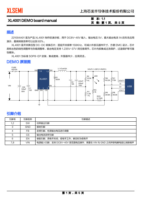
页数:第1 页,共5 页描述221004A01是为产品XL4001制作的演示板,用于DC8V~40V输入,输出电压5V,最大输出电流1A的车充应用演示,最高转换效率可以达到83%。
XL4001是开关降压型DC-DC转换芯片;固定开关频率150KHz,可减小外部元器件尺寸,方便EMC设计。
芯片具有出色的线性调整率与负载调整率,输出电压支持1.235V~37V间任意调节。
芯片内部集成过流保护、过温保护等可靠性模块。
XL4001为标准SOP8-EP封装,集成度高,外围器件少,应用灵活。
DEMO原理图FUSE引脚介绍页数:第2 页,共5 页物料清单页数:第3 页,共5 页性能数据转换效率转换效率:线性调整率和负载调整率:Efficiency VS Load currentEfficiency(%)Load current(A)Output voltage VS Output currentOutputvoltage(V)Output current(A)页 数:第 4 页, 共 5 页DEMO 实物图PCB 布局顶层底层页数:第5 页,共5 页应用信息输入电容选择在连续模式中,转换器的输入电流是一组占空比约为VOUT/VIN的方波。
为了防止大的瞬态电压,必须采用针对最大RMS电流要求而选择低ESR(等效串联电阻)输入电容器。
对于大多数的应用,1个4.7uF的输入电容器就足够了,它的放置位置尽可能靠近XL4001的位置上。
最大RMS电容器电流由下式给出:IRMS≈IMAX*√VOUT(VIN-VOUT)VIN其中,最大平均输出电流IMAX等于峰值电流与1/2峰值纹波电流之差,即IMAX=ILIM-△IL/2。
在未使用陶瓷电容器时,还建议在输入电容上增加一个0.1uF至1uF的陶瓷电容器以进行高频去耦。
输出电容选择在输出端应选择低ESR电容以减小输出纹波电压,一般来说,一旦电容ESR得到满足,电容就足以满足需求。
M27C4002中文资料
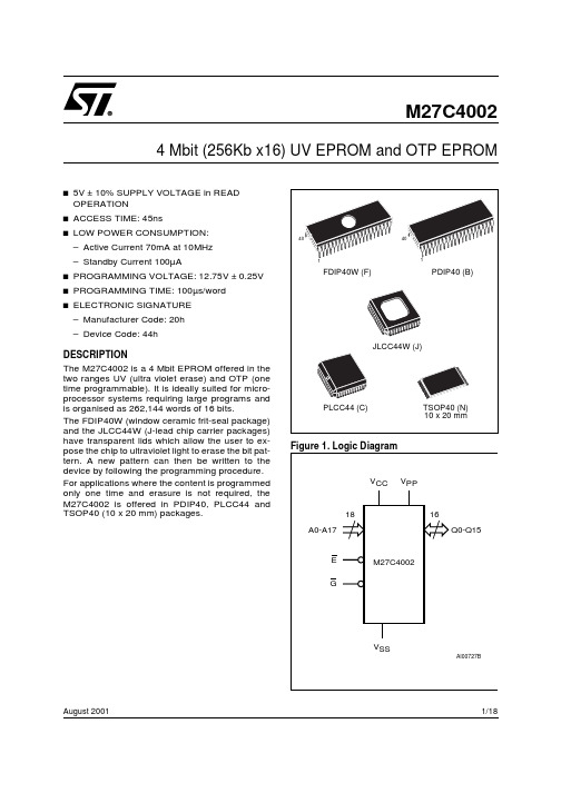
Table 3. Operating Modes
Mode
E
G
Read
VIL
VIL
Output Disable
VIL
VIH
Program
VIL Pulse
VIH
Verify
VIH
VIL
Program Inhibit
VIH
VIH
Standby
VIH
X
Electronic Signature
ble for at least tAVQV-tGLQV.
3/18
元器件交易网
M27C4002
Table 5. AC Measurement Conditions
Input Rise and Fall Times Input Pulse Voltages Input and Output Timing Ref. Voltages
AI01822
Figure 4. AC Testing Load Circuit
1.3V
1N914
DEVICE UNDER TEST
3.3kΩ CL
OUT
CL = 30pF for High Speed CL = 100pF for Standard CL includes JIG capacitance
– Active Current 70mA at 10MHz
– Standby Current 100µA
s PROGRAMMING VOLTAGE: 12.75V ± 0.25V
s PROGRAMMING TIME: 100µs/word
s ELECTRONIC SIGNATURE
xl400+使用手册
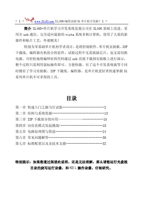
简介:XL400+单片机学习开发系统是我公司在XL400基础上改进,采用全usb通信,完全适应最新的vista系统多核计算机。
使用了大量的新器件和贴片工艺,外观精美!特别为零基础单片机初学者设计,是将控制软件、单片机实验板、ISP 下载线、编程器有机组合的套件,试验过程中无需拔插芯片,也无需切换电源。
可轻松地将编绎好的代码通过usb直接下载到实验板上进行演示,整个过程只需利用鼠标操作即可,方便快捷。
有了这个开发系统就等于同时拥有了学习实验板、ISP下载线、编程器。
是单片机爱好者快速掌握51系列单片机不可多得的工具。
目录第一章快速入门之跑马灯试验------------------------2第二章结构与系统资源------------------------------13第三章 ISP下载部分的应用———————------------15第四章向仿真模式发起挑战!------------------------18第五章电路原理图与简述---------------------------24第六章常见问题解答-------------------------------30第七章标准配置以及及技术支援---------------------32特别提示:如果您通过阅读此说明,还是无法理解,那么请您运行光盘根目录的烧写运行录像,和KEIL操作录像,仔细研究。
第一章:快速入门篇-用XL400+做跑马灯实验3:弹出“硬件安装”对话框,如果系统提示“没有通过Windows 徽标测试…”,不用理会,点击“仍然继续”,向导即开始安装软件;然后弹出“完成找到新硬件向导”对话框,点击完成。
4:系统第二次弹出“找到新的硬件向导”对话框,重复以上几个步骤完成安装。
你可以进入系统的:控制面板\系统\硬件\设备管理器中看到以下端口信息,表示系统已经正确的安装了USB驱动。
安装失败的解决方法:如果在安装中中途退出或掉电等,可能造成安装失败。
XL XL 系列使用手冊说明书

XLXL系列使用手冊著作權著作權所有 © 2017 年,BenQ Corporation。
所有權利均予保留。
未經BenQ Corporation 事前書面之許可,本文的任何部分皆不可以任何形式或任何方法,包括電子、機械、磁性、光學、化學、手寫或任何方式予以重製、傳輸、轉譯、儲存於檢索系統或翻譯成任何文字或電腦語言。
免責聲明對於本文之任何明示或暗示內容,BenQ Corporation不做任何保證,亦拒絕對任何特殊目的之商用性或適用性目的予以保證。
此外,BenQ Corporation保留修改或變更本文之權利,並且修改或變更內容將不另行通知。
不閃爍的效能表現,可能會受到諸多外在因素影響(例如訊號線品質不良、電源供應不穩、訊號干擾或接地不當),且並不侷限於以上述及的這些外在因素。
(僅適用於不閃爍的型號。
)BenQ ecoFACTSBenQ has been dedicated to the design and development of greener product as part of itsaspiration to realize the ideal of the "Bringing Enjoyment 'N Quality to Life" corporate vision with the ultimate goal to achieve a low-carbon society. Besides meeting international regulatory requirement and standards pertaining to environmental management, BenQ has spared noefforts in pushing our initiatives further to incorporate life cycle design in the aspects ofmaterial selection, manufacturing, packaging, transportation, using and disposal of the products.BenQ ecoFACTS label lists key eco-friendly design highlights of each product, hoping to ensure that consumers make informed green choices at purchase. Check out BenQ's CSR Website at / for more details on BenQ's environmental commitments andachievements.23電源安全說明•交流電插頭會將本設備與交流電電源隔離。
南黎科技三维扫描测量系统用户使用手册说明书
扫描标记点
优化标记点
设置背景面 标记点
保存扫描物件 的文件
扫描物件的 网格化
激光面片的 扫描
激光面片扫 描的设置
-8-
2、标记点扫描的设置
如图设置好适合餐具物件三维扫描的数值设置,如图一、图二设置。
图一
图二
3、扫描标记点操作
(1)选择扫描控制的“标记点”,点击“开始”,对扫描的工件进行激 光标记点的扫描,确保每一个点扫描完成后,点击“停止”。完成标记点扫描 操作。
-2-
三 运行环境
3.1 硬件设备 本系统需自带工作站机型便携式笔记本电脑。 打印机 windows 支持的打印机
四 使用过程
4.1 操作界面中主要对象使用说明: 1 菜单 2 页框 3 按钮 4 文本框 5 下拉列表框 6 单选按钮 7 微调框 8 滚动条 各类对象的使用方法介绍如下: 1 菜单 1) 图示:菜单的形式如下图所示:
1.2 背景 随着社会化的发展,现在的产品越来越趋向造型化、多样化、个性化。在生产制造过程 中需要对产品进行检测。 对于曲面造型复杂的产品高精度检测,这对于工业三维检测 工程是个大的挑战。 目前市场上大多以接触式的量测方式进行检测,有需制作精密的 检测工具,有需设计治具来定位,再用 CMM 三坐标进行测量,操作都相当的繁琐,得 准备相当复杂的前期工作和复杂的计算过程。所以就需要简单操作的三维检测,改变过 去检验的方法,以快速扫描的技术将量测物件资料,再以操作便捷的比对软件进行自动 分析计算,自动产生简而易懂的分析报表,达到产品检测的效果。该系统由厦门南黎科 技有限公司开发。使用者是车间人员、检测人员及有关人员。本系统广泛应用于航空航 天、汽车/轨道交通、机械制造、医疗康复、影视数字艺术、教学科研、文化遗产保护、 3D 打印、VR/AR 等领域,帮助企业实现品质、效率最优解,开拓更广的三维数字化领 域。满足高端制造领域的多项应用需求,包括三维检测,仿真模拟,逆向工程及产品改 造等。
BTS-4002(Chinese)

电池综合测试仪BTS-4002用户手册版本:1.0深圳市泰斯电子有限公司2012年3月l 在第一次使用本产品前,请详细阅读【用户手册】。
l 本机所附电源线内包含安全接地线,请确保电源插座安全接地线接地良好,在生产线场合固定使用时,请使用额外接地线连接机器后背板的安全接地螺丝孔。
l 本测试仪电路设计上不支持电池反接,在连接电池到电池测试仪前,请确认电池正负极和测试仪正负极连接线是否正确,如果反接,可能会因为电池放电电流过大导致电池或者测试仪器损坏。
l 本测试仪支持用户调整测试仪内部散热风扇运转速度,在环境温度高以及高负荷连续使用测试仪情况下,请勿将测试仪风扇速度设置为0,以免测试仪内部温度过高,影响测试精度或者导致测试仪故障。
l 本测试仪内无任何用户可以调整更换的零件或者保险丝等易损件,在未得到本公司书面许可情况下,严禁私自打开机壳,否则会影响设备保修目录1 产品概述 42 外观特性 52.1 前面板设计 52.2 键盘界面 62.3 接线端口72.4 后背板设计83 开机界面94 测试项目和参数设置104.1 参数说明104.2 测试功能描述124.3 测试步骤设置215 选项设置235.1 测试选项235.2 条码选项265.3 其他选项(信号指示)285.4 通信选项296 测试操作306.1 电池接线方式306.2 启动触发信号316.3 输出信号326.4 测试界面显示336.5 历史数据查看357 校准操作367.1 电压校准367.2 电压电流校准377.3 内阻校准387.4 其他参数校准398 特性指标401. 产品概述电池综合测试仪是一种能够快速检测电池的各项性能参数的专用测试设备,主要应用于电池生产厂家的电池生产检测,电池应用厂家电池来料检验等等用途,能够快速鉴别电池的性能指标,性能参数是否符合要求,能够根据设定参数快速判断电池是否为合格品。
深圳市泰斯电子有限公司成立多年,从最早第一代电池测试仪产品BTS-2002系列推向市场以来,得到电池生产厂家一致认同和广泛应用,在客户的大批量使用条件下,结合实际产品,不断升级;改善,从最早的1.0版本到最新的BTS-2002H的V5.9版,性能不断升级,在BTS-2002H基础上,升级到BTS-3002版本,也得到很多高端客户的认同,BTS-4002系列产品是在结合前两代的基础和优势下,新推出的最新一代电池测试仪产品,完全采用全新的设计,主控芯片采用ST公司新推出的32位ARM处理器,模拟器件采用ADI的高速16位模拟数字转换芯片,在整体精度和性能上有脱胎换骨的表现,具体表现在测试精度更高,测试速度更快,用户设置自定义更灵活,支持测试步骤自定义等等一系列的人性化改造升级。
Polycom RPX HD 400和200系列版本2.7.1发布说明书
Release NotesPolycom® RPX™ HD 400 and 200 SeriesVersion 2.7.1Polycom announces the general availability release of its Polycom RealPresence Experience™ (RPX) HD, version 2.7.1. This document provides the latest information about this release.TopicsIntroducing the Polycom RPX HD 2.7.1 Release (2)What’s New in RPX HD Version 2.7.1? (2)Software and Firmware Used in Version 2.7.1 (2)Upgrading the Software to Version 2.7.1 (3)Configuring the Content Monitors in Your RPX Suite (4)Issues Fixed in This Release (6)Known Issues and Limitations (7)For Users (7)For Administrators (9)Where to Get the Latest Product Information (10)Copyright Information© 2011 Polycom, Inc. All rights reserved.3725-25796-012/B (January 2011)Polycom, Inc.4750 Willow RoadPleasanton, CA 94588-2708USATrademark InformationPOLYCOM®, the Polycom "Triangles" logo and the names and marks associated with Polycom's products are trademarks and/or service marks of Polycom, Inc. and are registered and/or common law marks in the United States and various other countries. All other trademarks are property of their respective owners. No portion hereof may be reproduced or transmitted in any form or by any means, for any purpose other than the recipient's personal use, without the express written permission of Polycom.Introducing the Polycom RPX HD 2.7.1 ReleasePolycom is pleased to announce the release of the Polycom RPX HD 400 and 200 Series, version 2.7.1.The Polycom RealPresence Experience High Definition offers unprecedented high-definition video ina cinematic view, extraordinary StereoSurround™ audio, and high resolution content. This trulyimmersive meeting environment provides the ultimate meeting experience for executives in anyorganization, linking sites across the globe.What’s New in RPX HD Version 2.7.1?RPX HD version 2.7.1 is a maintenance release for RPX HD version 2.7, which provides the following functionality:∙Optimize bandwidth with H.264 High Profile, a standards-based video compression technology that delivers full HD quality while lowering your bandwidth requirements by up to 50 percent.H.264 High Profile is supported only on RPX HD systems with HDX 8000 series codecs.∙Simply and easily view a list of scheduled meetings and join those meetings using the Polycom Conferencing for Microsoft® Outlook® feature.∙Support for the new Delta VW7028 projector, which replaces the Delta VW7008 projector beginning in the first quarter of 2011.Information on the configuration of these and other RPX features is provided in the PolycomImmersive Telepresence (ITP) Administrator’s Guide.Software and Firmware Used in Version 2.7.1RPX HD version 2.7.1 uses the following software and firmware:∙Polycom Telepresence Tool version: 2.7.1.1 (TelepresenceTool_2.7.1.1.msi)∙Crestron software version: 2.7.1-1 (RPX_2.7.1-1.zip)∙Crestron AV2/PRO2 firmware version: 4.001.1012 (Feb 17 2009)(pro2_av2_cp2_cp2e_rack2_pac2_4.001.1012.zip)∙Crestron Touch Panel firmware version: 3.001.0015 (tps-3000_tps-3000l_tps-3100_tps-4000_tps- 4000l_3.001.0015.zip)∙HDX software version: polycom-hdx-hf-2.6.1.3_00_itp271-5267.pup∙HDX software version without encryption: polycom-hdx-hf-2.6.1.3_00_itp271_ne-5267.pup∙Delta projector firmware version for VW7008 projectors: FD31+SD30. The full file names are FD31-VW7008-20090907 and SD30-VW7008-2008090.∙Delta projector firmware version for VW7028 projectors: FP04+SP04. The full file names are FP04-VW7028BBCP-20101203 and SP04-VW7028BBCP-20100913.For information on versions of other Polycom products, such as RMX™ and CMA™, that are compatible with this release, refer to the Polycom Immersive Telepresence (ITP) Deployment Guide.Upgrading the Software to Version 2.7.1If the software at the RPX HD site is being upgraded to version 2.7.1 from an earlier version, theinstaller must follow these configuration procedures:1.Upgrade the Delta projector firmware if necessary.NOTE If you are upgrading the software to version 2.7.1 and your systemhas Delta projectors, you must ensure that the Delta projectorfirmware is at the correct version listed in the previous section. Thismay require you to upgrade the projector firmware. The firmwareupgrade must be performed onsite by a trained installer.2.Upgrade the HDX software.3.Configure the control system.4.Install and use the Telepresence Tool.5.Configure the Immersive Telepresence features.6.Align and calibrate the projectors (if you upgraded the projector firmware).7.Configure, align, and match the cameras (if you upgraded the projector firmware).The steps above are described in the Polycom RealPresence Experience (RPX) HD 400 Series Installation Guide, Version 2.7.1 or the Polycom RealPresence Experience (RPX) HD 200 Series Installation Guide,Version 2.7.1 as well as the Polycom Immersive Telepresence (ITP) Administrator’s Guide.Important Note: If your RPX HD system was installed after April 30, 2010 and you wish to upgrade from version 2.6 to version 2.7.1 software, you may need to obtain a new 1080p software license (part number 5150-26946-001) from Polycom. Please contact Polycom Customer Support at for more information.Configuring the Content Monitors in Your RPX Suite1.On the laptop, start the Polycom Telepresence Tool.2.The first time you use the Polycom Telepresence Tool with the RPX, the Select TelepresenceModel dialog box will appear and you must do the following:a.In the Select Model field, select the RPX system model.b.In the Select Main Display field, select the video format for the main displays installed inthe room.c.In the Select Content Display field, select Standard – VGA 1024x768.You must select Standard – VGA 1024x768 whether you have standard or widescreencontent monitors.d.Click OK.3.Press the Enter button on the content monitor to display the Configuration screen.4.Press the Right Arrow button on the screen to select Image Properties.5.Click OK.6.Press the Right Arrow button on the screen to select Scaling.7.Click OK.8.Select Full Screen.9.Click OK.10.If needed, press the Auto Sync button to make the content fill the screen.11.Repeat steps 3 through 10 for the remaining content monitors.Issues Fixed in This ReleaseRPX version 2.7.1 incorporates both HDX software version 2.6.1.3 and HDX hotfix version 2.6.1.3-HF5. HDX software version 2.6.1.3 provides a correction for an issue recently observed at the factory in which Polycom HDX systems restarted intermittently while in a call. HDX hotfix version 2.6.1.3-HF5 provides a correction to an intermittent lip sync issue.The following table lists the other issues fixed in RPX HD Version 2.7.1.Feature DescriptionAudio/Video Calls On rare occasions when placing a video or audio call with the Enhanced UI, the system may have automatically dialed the number before you pressed the Connect button.When viewing an RPX system in a 1080p multipoint call with an RMX 2000 or RMX 4000 with MPMx, you will no longer see a thin black vertical line between cells of the RPX system. For more information, refer to the Polycom® ImmersiveTelepresence (ITP) Deployment Guide.Touch Panel/ User Interface When joining a Polycom Conferencing for Microsoft Outlook (PCO) conference from the Touch Panel, you were not prompted for a conference password, even if a password was required for the meeting.With PCO, private meeting details were displayed on the Touch Panel, even if the Primary HDX system was not configured to Show Private Meeting Details.Known Issues and LimitationsFor UsersThe following table lists the known issues relevant to RPX HD end users.Feature DescriptionAudio/Video Calls The RPX will not accept any incoming audio calls when it is already in a video call.To avoid this issue, place outgoing audio calls instead of receiving incoming audio calls when you are already in a video call.When DTMF tones are heard during the process of dialing an audio call, the near-end and far-end audio is muted for a brief moment.If you hang up an incoming audio call and then immediately place an outgoing audio call, the RPX may not hang up the initial incoming audio call.To avoid this issue, wait five seconds between consecutive audio calls.If the RPX is in a single endpoint video call (such as with a VSX or HDX video conferencing system) and the Do Not Disturb feature on the RPX is disabled, an incoming call from a two-codec or three-codec system will cause the center camera on the RPX to momentarily move to the side before returning to its correct position.If the projectors are in sleep mode when an incoming video call is automatically accepted by the RPX, it may take up to 70 seconds for the projectors to automatically power up. During the 70 seconds that it takes for the projectors to warm up and show far-end video, the RPX meeting participants may not notice that the call has been established.To avoid this issue, verify that the projectors are powered up before placing or receiving any video calls.If the projectors are in sleep mode when a video call comes in, any codecs that are not being used will briefly show near-end video. This only occurs when the number of near-end codecs is more than the number of far-end codecs, such as when a RPX 400 on the near end receives an incoming call from an RPX 200 on the far end, or when either an RPX 400 or 200 receives an incoming call from a single endpoint (VSX or HDX).If you place a point-to-point call to an RMX Virtual Meeting Room (VMR) and then add a site to the call from the Conference List on the Meeting Composer screen (with the Enhanced UI only), the point-to-point call will be dropped and a multipoint call will be created with the VMR as a participant in that multipoint call.To avoid this, hang up the VMR call and then make a new call with the participants that you want in that call.If you are using Meeting Composer and you dial two audio sites concurrently, the Touch Panel may show that you are connected to the second audio number dialed when you are actually connected to the first number dialed.To avoid this issue, when want to connect to multiple audio sites or to both audio and video sites when using Meeting Composer, connect to the video sites first (if any), and then add the audio sites one at a time.When you place a call to an RMX VMR using the following syntax, the call will not go through: IP##MeetingRoomID.To avoid this issue, place the call using this syntax: MeetingRoomID@IP (for example,*************.130.21).Feature DescriptionAudio/Video Calls If you dial an incomplete IP address for a video call (for example, 172.16.254.), you may hear a ringing sound for approximately 90 seconds. Until the ringing ceases, you will be unable to place another call.Content If you share content using a laptop, for best results, set its input resolution to 1024x768 and its refresh rate to 75 Hz. This will ensure that the content image renders correctly.Document Cameras The Eye-10 document camera used in some custom solutions does not support the Freeze function that is available for other document camera models.Touch Panel/ User Interface If you press the Content button on the Touch Panel when no content source (such as a laptop) is connected to the RPX with the VGA cable, the Primary HDX codec will generate a hidden message on the Primary wall screen. The message states "PC input resolution and/or refresh rate not supported.” This message will not be visible onscreen because the RPX is programmed to picture mute all wall screens when the system is not in a call. If you establish a video call while the message is activated, the call will take longer than usual to connect. To avoid this issue, wait three seconds (during which time the message will time out) before placing a video call from the Touch Panel.In an audio call from an RPX to a cellular phone or analog phone, if the remote user disconnects the call first, the Touch Panel continues to show the audio call as in progress. To avoid this issue, manually press the Hang Up button after each audio call is completed. The RPX will not accept incoming audio or video calls when the Hang Up button is off hook.When searching for a site in the global directory with the Enhanced UI, up to nine characters can typically be displayed on the screen. However, depending on the width of the letters in the name, more or less of the site name may be truncated.With Meeting Composer, when dialing a phone number with more than 10 digits, or dialing anyotherlongstringsuchasextension@IP_address(ex:*************.130.201),the string will likely be truncated when displayed in the right-hand pane of the Touch Panel.If you place a point-to-point call to an RMX Virtual Meeting Room (VMR) and then add an audio-only site to the call, the two columns on the left side of the Meeting Composer screen in the Enhanced UI will go blank and the icons at the top of the columns will become grayed-out.When Polycom Conferencing for Microsoft Outlook (PCO) is used to schedule multiple meetings and you select one of the meetings on the Touch Panel, the details for that meeting display on the left side of the Touch Panel screen. If that meeting is cancelled, it is removed from the meeting list; however, the details of the cancelled meeting are still displayed on the left side of the Touch Panel screen.To fix this issue, simply select a different meeting from the meeting list.For AdministratorsThe following table lists the known issues relevant to RPX HD administrators.Feature DescriptionAudio/Video Calls When the primary codec answers an incoming video call, any HDX codecs that are not being used will automatically accept any other incoming video calls if the following conditions exist:1. The RPX 200 Series or RPX 400 Series is in a single endpoint video call with aVSX or HDX video conferencing system (video ad-hoc dialing).2. The RPX 400 is in a video call with an RPX 200 Series, a TPX™ 306M, or a TPX204M.To prevent unused codecs from accepting any incoming calls, use the Do Not Disturb timer. To change the amount of time before Do Not Disturb is activated, access the DoNotDisturbTimer field in the System_Config.ini file. In this field, you can enter a value between 10 and 300, or leave the value at 0 if you want to keep the feature disabled: DoNotDisturbTimer=x where x is the value (in seconds) of the desired timeoutperiod.For example, DoNotDisturbTimer=120 sets the parameter to 120 seconds.If you use the web UI to place a call that is not at the default call speed, the codecs will not automatically adjust to the same call speed. The Primary codec will connect at the call speed specified in the HDX web UI Call Quality field, but the remaining codecs will connect at the default call speed.To avoid this issue when placing a call using the web UI, connect to each codec individually at the desired call speed (if the desired call speed is different from the default).Avoid using the suffixes ‘1’, ‘2’, ‘3’, and ‘4’ for your audio speed dial name entries. Using these suffixes may cause the system to incorrectly interpret them as an ITP suite, instead of distinct audio speed dial entries.Avoid creating directory entries that have an “&” symbol in the name. If you do so, the entry will appear on the site list with the word “amp” in the name rather than the “&” symbol.When the RPX is in a call, sending Telnet commands to change the video format may not work properly.To avoid this issue, do not use Telnet commands to change the video format when the RPX is in a call.If you use the web UI to place a call that is not at the default call speed, the codecs will not automatically adjust to the same call speed. The Primary codec will connect at the call speed specified in the HDX web UI Call Quality field, but the remaining codecs will connect at the default call speed.To avoid this issue when placing a call using the web UI, connect to each codec individually at the desired call speed (if the desired call speed is different from the default).When an RPX calls another RPX in a point-to-point call, the codecs begin to connect one at a time. If network resources become limited, not all of the codecs may connect, which may make it appear that one of the projectors is not working properly. If a projector does not work correctly in a call, you should check if the codec connected. If it did not connect, reducing the call bandwidth may solve the issue.If your ITP environment is configured to use both the LDAP directory and H.323 Gatekeeper functions, and your speed dial entries are not IP addresses, video calls may take longer to connect due to the additional communication involved between the various components in the solution.Feature DescriptionControl System When you connect to the codecs through Telnet or through the Crestron Toolbox and use the command prompt, you may see “overflow buffer” and other error messages when you usethe Touch Panel. These errors also appear on the Crestron log. This issue does not affectsystem performance or functionality.Directory If you add a site from the CMA directory to the speed dial list and then later change the name of that site in the CMA, the speed dial entry name that is displayed on the Touch Panel maynot be updated.To fix this issue, reboot the codecs and the AV2 System Controller. Alternatively, from theHDX web UI, delete and re-add the renamed CMA site to the Speed Dial list.Microphones If you disconnect the Polycom Ceiling Microphone Arrays and then connect any microphones other than Ceiling Microphone Arrays, the proper stereo settings may be lost.If this occurs, launch the Polycom Telepresence Tool, make sure that all the HDX codecs areconnected, and then click Configure HDXs to set the microphones to their correct settings.Touch Panel/ User Interface If any of the HDX codecs are rebooted without rebooting the AV2 System Controller as well, the HDX UI remains onscreen.To avoid this issue, reboot the AV2 System Controller whenever any of the HDX codecs are rebooted. The VNOC, Service, and Site Administration teams are advised to reboot (power up) the AV2 System Controller after the HDX reboots (powers up) as part of the reset process or when recovering from a power failure. Placing a call without rebooting the AV2 System Controller will cause the Touch Panel to freeze.If you reboot the Primary HDX codec while the RPX is in an audio call (with the Help Desk, for example), the Hang Up button on the Touch Panel will freeze.To avoid this issue, reboot the AV2 System Controller when the Hang Up button enters that frozen state.Occasionally, the incorrect video format will be displayed on the Touch Panel Admin screen. To determine the correct video format:1. From the web UI, go to Admin Settings > Cameras.2. Check the Video Quality field for the camera being used. If VideoQuality=Sharpness, the video format is 1080p30; if Video Quality=Motion, thevideo format is 720p60.Alternatively, you can check the Video Format on the web UI Place a Call page.When initially loading the Crestron Touch Panel and then loading the AV2 System Controller, a Toolbox Results dialog box may appear at the end of the installation process. Although this dialog box displays an error message, the installation completed successfully.If users report that the Touch Panel seems to take an unusually long time to return directory information, check if there are LDAP entries in the directory that are no longer valid. If there are such entries, correct them.Where to Get the Latest Product InformationTo view the latest Polycom product documentation, visit the Support section of the Polycom website at .。
- 1、下载文档前请自行甄别文档内容的完整性,平台不提供额外的编辑、内容补充、找答案等附加服务。
- 2、"仅部分预览"的文档,不可在线预览部分如存在完整性等问题,可反馈申请退款(可完整预览的文档不适用该条件!)。
- 3、如文档侵犯您的权益,请联系客服反馈,我们会尽快为您处理(人工客服工作时间:9:00-18:30)。
ŋ
Electrical Characteristics (DC Parameters)
Vin = 12V, GND=0V, Vin & GND parallel connect a 220uf/50V capacitor; Iout=500mA, Ta = 25℃; the others floating unless otherwise specified. Parameters Input operation voltage Shutdown Supply Current Quiescent Supply Current Oscillator Frequency Switch Current Limit EN Pin Threshold Output Saturation Voltage Constant Voltage current sense Symbol Vin ISTBY Iq Fosc IL VEN VCE VCS VFB =0 High (Regulator OFF) Low (Regulator ON) VFB=0V ISW=2A VEN=5V VEN =0V, VFB =Vin 44 Test Condition Min. 4.5 80 2 52 3 1.4 0.8 1.1 1.4 Typ. Max. 40 200 5 60 Unit V uA mA Khz A V V V
2
Datasheet 2A 52KHz 40V Buck Li Battery Charger Function Block XL4002
Figure3. Function Block Diagram of XL4002
Typical Application Circuit (Car Charger)
60V
1A
6
Datasheet 2A 52KHz 40V Buck Li Battery Charger Package Information (SOP8-EP) XL4002
7
Note1: Stresses greater than those listed under Maximum Ratings may cause permanent damage to the device. This is a stress rating only and functional operation of the device at these or any other conditions above those indicated in the operation is not implied. Exposure to absolute maximum rating conditions for extended periods may affect reliabie
Temperature Range
XLSEMI Pb-free products, as designated with “E1” suffix in the par number, are RoHS compliant.
Absolute Maximum Ratings(Note1)
Parameter Input Voltage FB Pin Voltage EN Pin Voltage SW Pin Voltage Power Dissipation Thermal Resistance (Junction to Ambient, No Heatsink, Free Air) Operating Junction Temperature Storage Temperature Lead Temperature (Soldering, 10 sec) ESD (HBM) Symbol Vin VFB VEN VSW PD RJA TJ TSTG TLEAD Value -0.3 to 45 -0.3 to Vin -0.3 to Vin -0.3 to Vin Internally limited 50 -40 to 125 -65 to 150 260 2000 Unit V V V V mW ºC/W ºC ºC ºC V
Figure4. XL4002 Typical Application Circuit (Li Battery Charger)
3
Datasheet 2A 52KHz 40V Buck Li Battery Charger Ordering Information
Part Number Lead Free XL4002E1 XL4002TRE1 Marking ID Lead Free XL4002E1 XL4002E1 Packing Type Tube Tape & Reel
Wide 4.5V to 40V Input Voltage Range Output Adjustable from 1.235V to 37V
Minimum Drop Out 1.5V
Fixed 52KHz Switching Frequency 2A Constant Output Current Capability Internal Optimize Power Transistor
Excellent line and load regulation TTL shutdown capability ON/OFF pin with hysteresis function With output constant current loop
Built in thermal shutdown function Built in current limit function Built in output over voltage protection SOP8-EP (Exposed PAD) package
XL4002
System parameters test circuit figure4 VFB Efficiency Feedback Voltage Vin = 8V to 32V, Vout=5V Iload=0.2A to 2A Vin=12V ,Vout=5V Iout=2A 1.21 1.235 83 1.26 V %
4
Datasheet 2A 52KHz 40V Buck Li Battery Charger XL4002 Electrical Characteristics
Ta = 25℃;unless otherwise specified. Symbol Parameter Test Condition Min. Typ. Max. Unit
1 2 XL4002 3 4
8 7 6 5
VIN VIN EN CS
Figure2. Pin Configuration of XL4002 (Top View) Table 1 Pin Description Pin Number 1,2 3 4 5 6 7,8 Pin Name SW GND FB CS EN VIN Description Power Switch Output Pin (SW). Output is the switch node that supplies power to the output. Ground Pin.(Note: Connected the back exposed PAD to Pin3.) Feedback Pin (FB). Through an external resistor divider network, Feedback senses the output voltage and regulates it. The feedback threshold voltage is 1.235V. Output Current Sense Pin; (Iload=0.155V/Rcs) Enable Pin. Drive EN pin low to turn on the device, drive it high to turn it off. Floating is default low. Supply Voltage Input Pin. XL4002 operates from a 4.5V to 40V DC voltage. Bypass Vin to GND with a suitably large capacitor to eliminate noise on the input.
0.132 0.155 0.178
5
Datasheet 2A 52KHz 40V Buck Li Battery Charger XL4002
Schottky Diode Selection Table
Current Surface Through VR (The same as system maximum input voltage) Mount Hole 20V 30V 40V 50V 1N5817 1N5818 1N5819 √ √ √ 3A √ √ √ √ SR302 1N5820 MBR320 SK32 1N5821 MBR330 SK33 30WQ03 31DQ03 SR303 1N5822 MBR340 MBR350 SK34 31DQ04 SR304 SK35 31DQ05 SR305 SR306 30WQ04 30WQ05 MBR360 SK36
Datasheet 2A 52KHz 40V Buck Li Battery Charger Features
XL4002 General Description
The XL4002 is a 52 KHz fixed frequency PWM buck (step-down) DC/DC converter, capable of driving a 2A load with high efficiency, low ripple and excellent line and load regulation. Requiring a minimum number of external components, the regulator is simple to use and include internal frequency compensation and a fixed-frequency oscillator. The PWM control circuit is able to adjust the duty ratio linearly from 0 to 100%. An enable function, an over current protection function is built inside. An internal compensation block is built in to minimize external component count.
