catia英文学习ppt-2
☆CATIA 实例的英文教程(公司的培训材料)

In this course you will learn basic methods to create and modify solids features and parts
Targeted audience
New CATIA V5 Users
1 day
8
Part Design Workbench Presentation (4/4)
Terminology
A Part is a combination of one or more features, and bodies The first feature is generated from a sketch (profile), by extrusion or revolution Features are components based on sketches (sketch-based) or on existing features (dress-up and transformation). They can also be generated from surfaces (surface-based) A body is a set of features that can be assembled to a part through Boolean operations (Assemble, remove, ...)
p.10
p.11 p.14 p.15 p.18 p.20 p.23 p.24 p.25 p.28
3. Dressing-Up Features
Creating Drafts Variable Draft Angle Draft Angle: Cone Square Options Filleting Edges and Corners Edge Fillets with Limiting Planes, Faces or Surfaces
catia基础教学PPT1-2

Depth is where you enter the dimension for the depth of your pocket.
Click on Mirrored extent to “mirror” or send your pocket in both directions.
Since Catia automatically sends your pocket in the most logical direction, if you want it to go the other way click on Reverse Direction.
Notice that on your PARTS TREE, pad1 has been added BEFORE sketch1 that was already there. This is all part of Catia’s hierarchy system.
Congratulations! Your FIRST 3D part!
7
To CONSTRAIN, or dimension a part, first click on the line to be done as shown here…
picked
This is the CONSTRAINTS toolbar…
Defined in dialog box… Normal constraint… Auto Constraint… Animate constraint…
Now click on POCKET from the Sketcher Based Features toolbar… pocket
16
With POCKET picked, the POCKET DEFINITION input box will appear. Input the desired information and Catia will show you a dashed line sketch of your pocket. If all the information is correct, push APPLY and hole will appear in 3D, then push OK to make it permanent.
CATIA复合材料零件设计教程(英文)

p. 103
p. 107
p. 108 p. 109 p. 111 p. 115
10
Copyright DASSAULT SYSTEMES
Table of Contents (7/8)
MANБайду номын сангаасFACTURING DETAILED DESIGN 24. Manufacturing Data Structure
2
Planning (1/2)
DAY 1 MORNING
AFTERNOON
CATIA Options Foils
Exercises Foils
DAY 2 MORNING
AFTERNOON
Exercises Foils Exercises Foils Exercises Foils
Exercises Foils Exercises
3
Copyright DASSAULT SYSTEMES
Planning (2/2)
DAY 3 MORNING
AFTERNOON
DAY 4 MORNING
AFTERNOON
Foils
Exercises Foils Exercises Foils Exercises Foils Exercises Foils Exercises Foils
p. 65
p. 66 p. 67
p. 69
p. 70 p. 71
p. 72
p. 73 p. 74
p. 75
p. 76 p. 77
p. 78
p. 79 p. 80
8
Copyright DASSAULT SYSTEMES
Table of Contents (5/8)
2024版CATIA基础教程基本操作PPT课件

2024/1/26
实体变换
使用变换工具可以对选中的实体进行 移动、旋转、镜像等操作。
布尔运算
通过布尔运算工具可以对多个实体进 行合并、相减、相交等操作,从而得 到复杂的三维模型。
18
三维建模实例演示
实例一
创建简单零件:演示如何使用基 本实体创建工具和编辑工具来创 建一个简单的零件模型。
实例二
创建复杂装配体:展示如何使用 装配设计模块来创建包含多个零 件的复杂装配体,并进行装配约 束和动画演示。
在打印设置中可以选择打印机、 纸张大小、打印质量等参数确保 打印效果符合要求。
完成工程图设计后,可以通过 “文件”菜单中的“保存”命令 将工程图文件保存到指定位置。
2024/1/26
打印前建议进行预览检查确保打 印内容和排版正确无误。
27
THANKS
感谢观看
2024/1/26
28
添加视图时,可以选择不同的视图类型, 如主视图、俯视图、左视图等,根据实际 需求进行选择。
在工程图文件中,可以通过“插入”菜单 中的“视图”命令,将三维模型视图添加 到工程图中。
2024/1/26
在工程图设计界面中,选择“文件”菜单 中的“新建”命令,创建新的工程图文件。
在创建工程图文件时,需要设置图纸大小、 比例、单位等参数,根据实际需求进行设 置。
标题栏
显示当前打开的文档名称和 CATIA软件版本信息。
2024/1/26
工具栏
提供常用命令的快捷方式,方 便用户快速执行操作。
状态栏
显示当前操作状态和相关提示 信息。
9
菜单栏与工具栏功能
2024/1/26
文件菜单
包含新建、打开、保存、另存为、打印和退出等命令,用于管理 文档。
CATIA培训教材PPT(共 42张)

断面 工具条 – 点
点
(10 , 100mm / 10 = 10mm) 允许失真︰水平与垂直允许不同的大小的间隔
指令及工具条简介
圓倒截转立 角角断换体
几 何
作用中模组的主要工具,全部在 [ 插入 功能表 ] 內
建立约束条件 自动产生约束条件 驱动约束条件 断面 预先定义断面 圆 云形线 圆锥 线 轴 点
如何判断現在位于哪一個草图
断面 工具条 – 断面
断面
断面︰可连续建立 直线(预设)、相切圆弧、三点圆弧 的指令,完成 圆弧 后会自动回到 直线 3
6
7 8
一开始仅能使用直线或三点圆弧而无法使用相切圆弧 欲使用相切圓弧可拖动滑鼠左鍵可自动切换到相切圆弧 結束指令的方法︰ 1.封闭断面2.连击断面二下 3.按 ESC 二下 4.按图示
顏色代表的意义
灰色建构(参考)元件 黃色不可修改的元件
紅橙色已选取的元件 白色未约束的元件
增加约束条件
棕色无法改变的元件 绿色固定/基准/已约束的元件 紫色过度约束的元件
紅色不一致的元件
删除多余的尺寸约束
刪除多余的尺寸约束
增加尺寸约束或是改变尺寸數 值使其合理
草图工具组 工具条
网格交点
4
5
2
4
5
5
1
2
1
1 3
2
1
3 4
3 4
2
断面 工具条 – 线
直线
2 1
2
从草图工具组中输入尺寸
1
无限长的直线
1
1
2 1
断面 工具条 – 线 及 轴
双切线
点在切点的附近即可
平分线
2 1
轴
2024版CATIA基本进阶培训教材课件pptx

CATIA基本进阶培训教材课件pptx•CATIA软件概述•CATIA基本操作•零件设计基础•装配设计基础目录•工程图设计基础•CATIA高级功能介绍CATIA软件概述01 02 03模具设计提供模具设计全流程解决方案,包括分型面设计、模架设计等提供专业的钣金设计工具,支持折弯、展开等操作工程图设计生成符合国家标准的工程图纸,支持多种标注和符号零件设计提供丰富的建模工具,支持复装配设计航空航天车身、底盘、动力系统等的设计和制造汽车机械制造消费电子01020403手机、平板电脑等外观和结构的设计和制造飞机、发动机等复杂产品的设计和制造机床、模具、轴承等的设计和制造CATIA 软件应用领域CATIA基本操作界面介绍123工具栏功能标准工具栏视图工具栏测量工具栏其他专业工具栏基本操作命令编辑操作命令选择操作命令撤销、重做、剪切、复制、粘贴等单选、框选、按类型选择等选择方式及技巧文件操作命令视图操作命令其他常用命令新建、打开、保存、另存为、关闭等缩放、旋转、平移、视图定向等隐藏/显示、图层管理、属性查看与修改等零件设计基础草图基本概念草图绘制工具草图约束草图编辑与修改草图设计了解实体建模的原理、特点及在CATIA 中的实现方式。
实体建模基本概念基本实体创建实体编辑与修改特征树与图层管理学习使用拉伸、旋转、扫描、放样等方法创建基本实体。
掌握布尔运算、倒角、圆角、抽壳等实体编辑工具,实现复杂实体建模。
了解特征树的结构与功能,学习图层的创建与管理方法,提高建模效率。
实体建模曲面设计基本概念了解曲面设计的原理、应用及在CATIA中的实现方式。
基本曲面创建学习使用拉伸、旋转、扫描、放样等方法创建基本曲面。
曲面编辑与修改掌握曲面修剪、延伸、倒角、圆角等编辑工具,实现复杂曲面设计。
曲面分析工具了解曲面分析工具的使用方法,如曲率分析、连续性检查等,确保曲面质量。
曲面设计装配设计基础创建新的装配文件在CATIA中,选择“开始”菜单,然后选择“机械设计”或“装配设计”来创建一个新的装配文件。
CATIA 培训_PPT_catia资料(英文)2

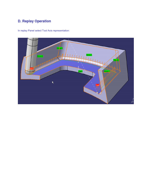
D. Replay OperationIn replay Panel select Tool Axis representation:Step 2: COMBIN TANTO strategyRe-use CATprocess created in previous step or openData\Ex01-TantoFan\Process_final.CATprocessA. Operation DefinitionSelect previous Multi-Axis Flank Contouring operation created, copy/paste it, edit duplicated operation. In Tool Axis Tab, select Combin Tanto strategy, and keep 5mm as Leave and approach distance.B. Replay OperationNow you can modify leave and approach distance (increase or decrease) to see the impact of fanning distance on tool axis.Step 3: COMBIN PARELM strategyRe-use CATprocess created in previous step or openData\Ex02-CombinTanto\Process_final.CATprocessA. Operation DefinitionSelect previous Multi-Axis Flank Contouring operation created, copy/paste it, edit duplicated operation. In Tool Axis Tab, select Combin Parelm strategy, and keep 5mm as Leave and approach distance.B. Replay OperationNow you can modify leave and approach distance (increase or decrease) to see the impact of fanning distance on tool axis.Step 4: MIXED COMBIN strategyOpen Data\Process_start_combinmixed.CATProcessA. Geometry SelectionSelect pocket bottom as Part, select pocket walls as drive, select ZX plane as Start and Stop element (ON conditions).B. Strategy DefinitionSelect Mixed Combin guidance with 5mm for approach and leave distance. Select Close tool path option.C. Replay OperationStep 5: Finish 5 axis flanks of pocket Open Data\Process_start2.CATProcessA. Geometry SelectionPart element is bottom of pocket, Drives element are flanks of pocket.Start element is the web in front of pocket.Stop element is vertical wall in front of pocket.On conditions for both start and stop.B. Strategy DefinitionMachining Tab: keep default parametersStepover Tab: select axial By offset mode, 4 levels of 10mmFinishing Tab: select At last level, with 1mm thicknessTool Axis Tab: select Tanto Fan strategy.C. Tool DefinitionSelect or create an END Mill with D=16mm and Rc=4mm D. Replay Operation。
catia基础培训课件2

(接catia基础培训课件1)动画演示3、倒角(chamfer)动画演示4、创建拔模角(draft angle)动画演示动画演示动画演示动画演示动画演示动画演示5、抽壳(shell)动画演示6、长厚度(thickness)动画演示7、螺纹(Thread/Tap)动画演示四)对零件体操作1、零件体组合(assemble)动画演示动画演示2、零件体相加(add)动画演示3、零件体相减(remove)动画演示4、零件体求交(intersect)动画演示五)特征移动操作1、沿直线移动零件体特征(translation)动画演示2、旋转零件体(rotation)动画演示3、镜像零件体(symmetry)动画演示4、特征对称复制(mirror)动画演示5、矩形图样(rectangular pattern)动画演示6、环形图样(circular pattern)动画演示7、用户自定义图样(user pattern)动画演示8、比例缩放(scaling)动画演示三、实例:方形烟灰缸1、草绘2、拉伸3、拔模4、以上表面作为草绘平面创建草绘5、拉伸切割6、内表面拔模7、外棱线倒圆角8、内棱线倒圆角9、建立草绘,创建搁置烟槽10、拉伸切割11、生成另外一方向的切割12、底面倒圆角13、顶面倒圆角14、抽壳(shell)15、最终样式第四章创成式外形设计CATIA V5的创成式外形设计(GSD)模块包括线框和曲面造型功能,它为用户提供了一系列应用广泛、功能强大、使用方便的工具集,以建立和修改用于复杂外形设计所需的各种曲面。
同时,创成式外形设计方法采用了基于特征的设计方法和全相关技术,在设计过程中能有效地捕捉设计者的设计意图,因此极大地提高了设计者的质量与效率,并为后续设计更改提供了强有力的技术支持。
参考元素可以使用“视图(View)”>“工具栏(Toolbars)”>“参考元素(扩展/压缩)(Reference Elements (extended/compact))”显示参考元素工具栏。
catia教材2

Foils
Assembly Design Fundamentals
Version 5 Release 9 June 2002 EDU-CAT-E-ASM-FF-V5R9
Copyright DASSAULT SYSTEMES 2002
1
Course Presentation
Design parts in the context of the assembly
Capture various states of the assembly for analyzing the design and preparing for drafting
Copyright DASSAULT SYSTEMES 2002
Objectives of the course
In this course you will learn to create and manage CATProduct files.
Targeted audience
CATIA V5 users
Prerequisites
Part Design Courses
146
147 156 160 167 173 178 182
7.
Flexible Sub-Assemblies
Flexible Sub-Assemblies What can you Do with Flexible Sub-Assemblies ? Managing Flexible Sub-Assemblies with Several Levels Propagating Position to Reference
Update Catalog Browser Measure Between Measure Item Measure Inertia
CATIA学习ppt课件

特征树:
可以移动、放大、 缩小、隐藏(F3)、 修改
草图: 可以用菜单”插入” 或者点击图标
特征: 可以用菜单”插入” 或者点击图标
9
界面及板块
常用视图选项
10
界面及板块
常用视图选项
11
界面及板块
常用视图选项
12
汇报完毕,感谢聆听!
13
中文名:交互式CAD/CAE/CAM系统 英文名:Cnal Interactivity Application
1. CATIA具备先进的混合建模技术 设计对象的混合建模:在CATIA的设计环境中,无论是实体还是曲面, 做到了真正的交互操作;变量和参数化混合建模:在设计时,设计者不必考 虑如何参数化设计目标,CATIA提供了变量驱动及后参数化能力。 几何和智能混合建模:对于一个企业,可以将企业多年的经验积累到 CATIA的知识库中,用于指导本企业的新手,或者指导新车型的开发,加速 新型号推向市场的时间。 CATIA具有在整个产品周期内的方便的修改能力,尤其时后期修改性 无论是实体建模还是曲面造型,由于CATIA提供了智能化的树结构,用户可 方便快捷的对产品进行重复修改,即使是在设计的最后阶段需要做重大的修 改,或者是对原有方案的更新换代,对于CATIA来说,都是非常容易的事0
4
界面及板块
鼠标的使用
5
界面及板块
新建一个CATIA文件
Ctrl + N
6
界面及板块
CATIA V5R20界面
标题栏 特征树
菜单栏
工作窗口
菜单栏
工具栏
指南针 (罗盘)
坐标平面 命令行
7
界面及板块
指南针应用
指南针(罗盘): 可以旋转、移动、 隐藏
CATIAV5基础培训培训课件.ppt

草绘平面
(一)草绘基本操作
CATIA V5 Training
2、诊断(Diagnostics)
该选项默认为先择状态,当加约束时,图素颜色会变化,以此来判断约束是否完全、更新等
3、尺寸约束(Dimensional Constrains)
该选项默认为选择状态,当加尺寸约束时,尺寸才会显示,如该选项没有选中,测所加尺寸约束全部不可见
CATIA V5 Training
1、网格参数设定(Grid)
网格显示(Display):选中该项,则在草绘环境显示网格。 网格自动捕捉(Snap to point):草绘时自动捕捉网格点。 允许不等距设置(Allow Distortions):允许V方向网格线不等于H方向 主网格线(Primary Spacing):此处数值代表主网格线距离 刻度(Graduations):此处数值代表主网格线之间网格数目
4、几何约束(Gemetrical Constrains)
该选项默认为选择状态,如该选项没有选中,则所加约束全的约束符号全部不可见
CATIA V5 Training (二)轮廓创建(Profile)
1、创建直线和圆组成的轮廓 点击 ,草绘工具栏如下所示: 可在数值框内键入坐标值或直接在屏幕上点击,画直线点击 ,画相切圆点击 , 画三点圆点击 ,若所画轮廓封闭则自动退出命令。若需不封闭轮廓,可在所需轮廓 最终位置双击或再次点击即可 。使用该命令绘制结果可如下:
CATIA V5 Training
三、轮廓创建工具条
CATIA V5 Training
四、几何操作工具条
CATIA V5 Training
五、约束命令工具条
Constraints Defined in Dialog Box 使用对话框进行约束 Constraint 创建快速约束 Contact Constraint 创建接触几何约束 Auto Constraint 自动创建约束 Fix together Constraint 把图素约束在一起 Animate Constraint 模拟约束效果 Edit Mul- Constraint 编辑多个约束
CATIA教程基础操作 ppt课件

2021/3/26
CATIA教程基础操作 ppt课件
1
CATIA教程
2021/3/26
CATIA教程基础操作 ppt课件
2
CATIA培训
第一章 CATIA V5的三维世界
2021/3/26
CATIA教程基础操作 ppt课件
3
第一章 目录
★第一节 基本介绍 ★第二节 CATIA V5 体系结构 ★第三节 CATIA V5 通用操作 ★第四节 CATIA V5的环境设置
菜单项包含了所有的操作命令。 利用工具按钮可完成大部分操作命令的快速启动。 利用对话框可进行某些设计参数的选择和定义。 设计树利用树状结构记录了设计历程。 罗盘是一个十分便利的设计工具,具有很多功能。 窗体内用于设计的工作空间。
包括坐标系、参考平面及命令栏等。
CATIA教程基础操作 ppt课件
8
菜单
设备与系统工程模组 Equipment & Systems
机械设计模组 Mechanical Design
知识工程模组 Knowledgeware
CATIA V5
曲面设计模组 Shape
电子样机模组 Digital Mockup
数控加工模组 Machining
人机工程模组 Ergonomics
Design & Analysis
实时渲染
Real
Time Rendering
DELMIA D5接口 DELMIA D5 Integration
CATIA教程基础操作 ppt课件
图片工作室 Photo Studio
11
第一章 CATIA V5的三维世界
二、机械设计模组
CATIA培训教程PPT教学课件

目录
第一篇 第二篇 第三篇 第四篇 第五篇
GSD模块命令简介………………………………………… 4 车身设计常用命令详解…………………………………… 12 应用实例…………………………………………………… 53 实用技巧…………………………………………………… 72 作业………………………………………………………… 75
5. 圆心点(Circle center):
它用于生成所选择圆(Circle)的圆心点。
6. 曲线的切点(Tangent on curve):
注:浅蓝色所示部分为必须掌握的, 黄色的为应该掌握的,其他随意。
它用于生成指定曲线(Cu第rv1e1)页/在共指78定页方向(Direction)上的切点。
在CATIA V5中提供了多种生成直线的方法。如果指定支撑面,最后生成的直线
第一篇gsd模块命令简介几何操作operations图标join合并几何元素线面healing缝补曲面curvesmooth曲线光顸untrim恢复被剪切曲面disassemble分解几何元素split切割曲面戒线框元素trim修剪曲面戒线框元素boundary提叏曲面边界线extract提叏几何体multipleedgeextract从草图中提叏部分几何体shapefillet两曲面倒圆edgefillet曲面棱线倒圆variablefillet发半径倒圆facefacefillettritangentfillet三面相切倒圆translate平秱几何体rotate转动几何体symmetry对称几何体scaling缩放几何体affinityaxis将几何体秱动到另一坐标系中extrapolate延长曲线曲面invertorientation曲线曲面反向near从组合体中提叏不参考对象最近部分的元素几何操作
- 1、下载文档前请自行甄别文档内容的完整性,平台不提供额外的编辑、内容补充、找答案等附加服务。
- 2、"仅部分预览"的文档,不可在线预览部分如存在完整性等问题,可反馈申请退款(可完整预览的文档不适用该条件!)。
- 3、如文档侵犯您的权益,请联系客服反馈,我们会尽快为您处理(人工客服工作时间:9:00-18:30)。
CATIA V5 Workbook
CATIA V5 Workbook * Southern Utah University * Schroff Development Corporation* Corporate Visual Systems
10. Creating A pattern of Holes
Select (Hole 1)
Select this edge to specify direction
Distance dim.
11. Modifying the Width of the Base Leg
Select here
Double click here
14. Creating A Symmetrical “L Shaped Extrusion”
Select this surface
15. Mirroring The “L Shaped Extrusion”
Select this surface
Select the chamfer and delete it or delete it from the specification tree.
Figure 4.39
Free rotation handle Rotate on X Axis Translate on X Axis on Y Rotate Axis Translate on Y Axis Translate on Z Axis Rotate on Z Axis Compass Move Box
Pad Pocket Shaft Groove Hole Rib Slot Solid Combine Loft Removed Loft
Pad
Drafted Filleted Pad
Multi-Pad Pocket
Drafted Filleted Pocket
Multi-Pocket Solid Combine
The Annotations Tool Bar
Text With Leader Flag Note
The Constraints Tool Bar
Constraints Defined In Dialog Box
Constraint
The Surface-Based Features Tool Bar
6. Creating A Fillet
Select
New Fillet added
2x .5″ Fillets
7. Creating A Fillet on the Back Edge of the “L Shaped Extrusion”
Center of rotation Select this edge to be filleted
19. Managing the Specification Tree 20. Customizing the Specification Tree
Select Part1
With part1 highlighted, right click, select the Properties option. Change the name to “T Shaped Extrusion”
12. Translating the “L Shaped Extrusion”
Pos. & neg. direction of translation
Select this edge for direction
13. Rotating the “L Shaped Extrusion”
Rotation Sub options will be available when arrow is selected. Select this line for axis of rotation
Chamfer Shell Thickness Thread/Tap Remove Face Replace Face
Edge Fillet Variable Radius Fillet Face-Face Fillet Tritangent Fillet Draft Angle Draft Reflect Line Variable Draft
Filleted edge
8. Creating A Chamfer
Select here and delete or cut Different mode options:
9. Creating Holes
Select this surface Edge 1 Edge 2
Depth dim.
Vertical dim. Horizontal dim. Diameter dim.
Select here Select here
18. Applying Material to the “T Shaped Extrusion”
Select part from Tree Select this view mode to see the applied material Select Metal Tab Select Material
Send Questions and/or Comments to COZZENS@
Part Design Workbench Tool Bars
The Sketcher Tool Bar (Access The Sketcher Workbench)
Sketcher
The Sketch-Based Features Tool Bar
Stiffener
The Transformation Features Tool Bar
Scaling Mirror Translation Rotation Symmetry Rectangular Pattern Circular Pattern User Pattern
The Dress-Up Features Tool Bar
Thick Surface Split Close Surface Sew Surface
Steps to Extruding A Profile Using The Part Design Workbench
1. Start CATIA V5
2. Select The Part Design Workbench 3. Open The “L-Shaped Extrusion.CATPart” Document 4. Review the “L Shaped Extrusion.CATPart” 5. Extruding The Sketcher Profile Using The Pad Tool
21. Reviewing the Design Process Using the Specification Tree
22. Save the Completed “T Shaped Extrusion” Before It Gets Away 23. Exit CATIA V5
Mirror.1 added to the Specification Tree New Mirrored part
16. Scaling The “T Shaped Extrusion”
Selectre chamfer!
17. Applying Constraints in the Part Design Workbench
Objectives
How to select the Part Design Workbench How to open the “L Shaped Extrusion.CATPart” How to review Pad creation. How to create several different Fillets How to create a Chamfer How to create and place Holes How to create Patterns How to modify the existing “L Shaped Extrusion” How to Translate entities How to Rotate entities How to use the Symmetry tool How to Mirror entities How to Scale entities How to create Part Design Constraints How to Apply Material to entities How to manage the Specification Tree How to customize the Specification Tree How to Review the design process How to Save the document How to Exit CATIA V5 (review)
