RCD16-47B6中文资料
N32G4FR系列勘误手册V1.0说明书

N32G4FR系列勘误手册V1.0目录1 勘误列表 (1)2 电源控制(PWR) (3)2.1S TOP2模式唤醒 (3)3 复位和时钟控制(RCC) (4)3.1系统定时器(S YSTICK) (4)4 GPIO和AFIO (5)4.1SPI1从模式,USART2同步模式 (5)4.2SPI1主模式,USART2同步模式 (5)4.3SPI2从模式,USART3同步模式 (5)4.4SPI2主模式,USART3同步模式 (5)5 模拟/数字转换(ADC) (6)5.1ADC数据左对齐 (6)5.2ADC模拟看门狗 (6)5.3ADC注入通道触发规则通道转换 (6)5.4从ADC转换受主ADC转换影响启动 (7)5.5相邻ADC数据寄存器受影响 (7)6 串行外设接口(SPI) (8)6.1SPI接口 (8)6.1.1 SPI波特率设置 (8)6.1.2 从模式CRC校验 (8)6.2I2S接口 (9)6.2.1 PCM长帧模式 (9)7 I2C接口 (10)7.1当前字节传输前必须被管理的软件事件 (10)7.2单次读取单或双字节时的注意事项 (10)7.3与其他外设同时使用DMA (11)8 通用同步异步接收器(USART) (12)8.1校验错误标志 (12)8.2RTS硬件流控 (12)9 调试接口(DBG) (13)9.1D EBUG寄存器 (13)10 定时器(TIM) (14)10.1定时器重复捕获检测 (14)11 实时时钟(RTC) (15)11.1RTC预分频 (15)11.2RTC校准 (15)11.3RTC计时 (15)12 芯片丝印及版本说明 (16)13 版本历史 (17)14 声明 (18)1勘误列表表1-1勘误概述2电源控制(PWR)2.1Stop2模式唤醒描述MCU处于Stop2模式,如在被唤醒的同时发生NRST复位,NRST不能复位MCU,唤醒优先,MCU将先响应唤醒。
调速器硬件手册

ETD 790直流调速器
页码:2 /86
ETD 790直流调速器 电流预测控制
6.4e 模拟输出 .............................................................................................................. 39 6.4f 422/485串行口....................................................................................................... 41 6.4g 直流测速电机反馈接线 ......................................................................................... 42 6.4h 用于指示输入和输出的LED指示器 ....................................................................... 43 6.5 RS 232、CAN总线、编码器1、编码器2的连接器....................................................
常用稳压管型

常用稳压管型 The manuscript was revised on the evening of 2021常用稳压型号参数查询DZ是稳压管的电器编号,1N4148就是一个的稳压管,下面是稳压管上的编号对应的稳压值,有些小的稳压管也会在管体上直接标稳压电压,如5V6就是的稳压管。
美标稳压二极管型号:HITACHI(日立):HITACHI(日立)稳压二极管型号参数稳压HZ3A1 ~HZ3A2 ~HZ3A3 ~HZ3B1 ~HZ3B2 ~HZ3B3 ~线性稳压器件(输入输出电流相等,压降3V以上) 型号稳压(V) 最大输出电流可替代型号79L05 -5V 100mA79L06 -6V 100mA79L08 -8V 100mALM7805 5V 1A L7805,LM340T5LM7806 6V 1A L7806LM7808 8V 1A L7808LM7809 9V 1A L7809LM7812 12V 1A L7812,LM340T12LM7815 15V 1A L7815,LM340T15LM7818 18V 1A L7815LM7824 24V 1A L7824LM7905 -5V 1A L7905LM7906 -6V 1A L7906,KA7906LM7908 -8V 1A L7908LM7909 -9V 1A L7909LM7912 -12V 1A L7912LM7915 -15V 1A L7915LM7918 -18V 1A L7918LM7924 -24V 1A L792478L05 5V 100mA78L06 6V 100mA78L08 8V 100ma78L09 9V 100ma78L12 12V 100ma78L15 15V 100ma78L18 18V 100ma78L24 24V 100ma开关稳压器件(电压转换效率高)型号说明最大输出电流简易开关电源稳压器 1A5V简易开关电源稳压器 1ALM1575T-12 12V简易开关电源稳压器 1ALM1575T-15 15V简易开关电源稳压器 1ALM1575T-ADJ 简易开关电源稳压器(可调~37V) 1A简易开关电源稳压器 1A5V简易开关电源稳压器 1ALM1575HVT-12 12V简易开关电源稳压器 1A LM1575HVT-15 15V简易开关电源稳压器 1A LM1575HVT-ADJ 简易开关电源稳压器(可调~37V) 1A 简易开关电源稳压器 1A5V简易开关电源稳压器 1ALM2575T-12 12V简易开关电源稳压器 1A LM2575T-15 15V简易开关电源稳压器 1A LM2575T-ADJ 简易开关电源稳压器(可调~ 37V) 1A简易开关电源稳压器 1A5V简易开关电源稳压器 1ALM2575HVT-12 12V简易开关电源稳压器 1A LM2575HVT-15 15V简易开关电源稳压器 1A LM2575HVT-ADJ 简易开关电源稳压器(可调~37V) 1A 简易开关电源稳压器 3A简易开关电源稳压器 3ALM2576T-12 12V简易开关电源稳压器 3A LM2576T-15 15V简易开关电源稳压器 3A LM2576T-ADJ 简易开关电源稳压器(可调~37V) 3A简易开关电源稳压器 3A简易开关电源稳压器 3ALM2576HVT-12 12V简易开关电源稳压器 3A LM2576HVT-15 15V简易开关电源稳压器 3A LM2576HVT-ADJ 简易开关电源稳压器(可调~37V) 3A。
2016新编CD系列引脚大全
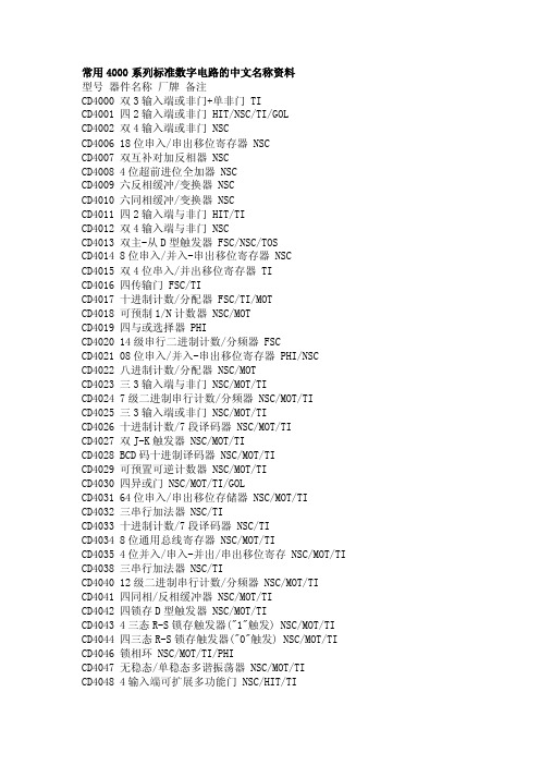
常用4000系列标准数字电路的中文名称资料型号器件名称厂牌备注CD4000 双3输入端或非门+单非门 TICD4001 四2输入端或非门 HIT/NSC/TI/GOLCD4002 双4输入端或非门 NSCCD4006 18位串入/串出移位寄存器 NSCCD4007 双互补对加反相器 NSCCD4008 4位超前进位全加器 NSCCD4009 六反相缓冲/变换器 NSCCD4010 六同相缓冲/变换器 NSCCD4011 四2输入端与非门 HIT/TICD4012 双4输入端与非门 NSCCD4013 双主-从D型触发器 FSC/NSC/TOSCD4014 8位串入/并入-串出移位寄存器 NSCCD4015 双4位串入/并出移位寄存器 TICD4016 四传输门 FSC/TICD4017 十进制计数/分配器 FSC/TI/MOTCD4018 可预制1/N计数器 NSC/MOTCD4019 四与或选择器 PHICD4020 14级串行二进制计数/分频器 FSCCD4021 08位串入/并入-串出移位寄存器 PHI/NSCCD4022 八进制计数/分配器 NSC/MOTCD4023 三3输入端与非门 NSC/MOT/TICD4024 7级二进制串行计数/分频器 NSC/MOT/TICD4025 三3输入端或非门 NSC/MOT/TICD4026 十进制计数/7段译码器 NSC/MOT/TICD4027 双J-K触发器 NSC/MOT/TICD4028 BCD码十进制译码器 NSC/MOT/TICD4029 可预置可逆计数器 NSC/MOT/TICD4030 四异或门 NSC/MOT/TI/GOLCD4031 64位串入/串出移位存储器 NSC/MOT/TICD4032 三串行加法器 NSC/TICD4033 十进制计数/7段译码器 NSC/TICD4034 8位通用总线寄存器 NSC/MOT/TICD4035 4位并入/串入-并出/串出移位寄存 NSC/MOT/TI CD4038 三串行加法器 NSC/TICD4040 12级二进制串行计数/分频器 NSC/MOT/TICD4041 四同相/反相缓冲器 NSC/MOT/TICD4042 四锁存D型触发器 NSC/MOT/TICD4043 4三态R-S锁存触发器("1"触发) NSC/MOT/TI CD4044 四三态R-S锁存触发器("0"触发) NSC/MOT/TI CD4046 锁相环 NSC/MOT/TI/PHICD4047 无稳态/单稳态多谐振荡器 NSC/MOT/TICD4048 4输入端可扩展多功能门 NSC/HIT/TICD4049 六反相缓冲/变换器 NSC/HIT/TICD4050 六同相缓冲/变换器 NSC/MOT/TICD4051 八选一模拟开关 NSC/MOT/TICD4052 双4选1模拟开关 NSC/MOT/TICD4053 三组二路模拟开关 NSC/MOT/TICD4054 液晶显示驱动器 NSC/HIT/TICD4055 BCD-7段译码/液晶驱动器 NSC/HIT/TI CD4056 液晶显示驱动器 NSC/HIT/TICD4059 “N”分频计数器 NSC/TICD4060 14级二进制串行计数/分频器 NSC/TI/MOT CD4063 四位数字比较器 NSC/HIT/TICD4066 四传输门 NSC/TI/MOTCD4067 16选1模拟开关 NSC/TICD4068 八输入端与非门/与门 NSC/HIT/TICD4069 六反相器 NSC/HIT/TICD4070 四异或门 NSC/HIT/TICD4071 四2输入端或门 NSC/TICD4072 双4输入端或门 NSC/TICD4073 三3输入端与门 NSC/TICD4075 三3输入端或门 NSC/TICD4076 四D寄存器CD4077 四2输入端异或非门 HITCD4078 8输入端或非门/或门CD4081 四2输入端与门 NSC/HIT/TICD4082 双4输入端与门 NSC/HIT/TICD4085 双2路2输入端与或非门CD4086 四2输入端可扩展与或非门CD4089 二进制比例乘法器CD4093 四2输入端施密特触发器 NSC/MOT/STCD4094 8位移位存储总线寄存器 NSC/TI/PHICD4095 3输入端J-K触发器CD4096 3输入端J-K触发器CD4097 双路八选一模拟开关CD4098 双单稳态触发器 NSC/MOT/TICD4099 8位可寻址锁存器 NSC/MOT/STCD40100 32位左/右移位寄存器CD40101 9位奇偶较验器CD40102 8位可预置同步BCD减法计数器CD40103 8位可预置同步二进制减法计数器CD40104 4位双向移位寄存器CD40105 先入先出FI-FD寄存器CD40106 六施密特触发器 NSC\TICD40107 双2输入端与非缓冲/驱动器 HAR\TICD40108 4字×4位多通道寄存器CD40109 四低-高电平位移器CD40110 十进制加/减,计数,锁存,译码驱动 STCD40147 10-4线编码器 NSC\MOTCD40160 可预置BCD加计数器 NSC\MOTCD40161 可预置4位二进制加计数器 NSC\MOTCD40162 BCD加法计数器 NSC\MOTCD40163 4位二进制同步计数器 NSC\MOTCD40174 六锁存D型触发器 NSC\TI\MOTCD40175 四D型触发器 NSC\TI\MOTCD40181 4位算术逻辑单元/函数发生器CD40182 超前位发生器CD40192 可预置BCD加/减计数器(双时钟) NSC\TICD40193 可预置4位二进制加/减计数器 NSC\TICD40194 4位并入/串入-并出/串出移位寄存 NSC\MOT CD40195 4位并入/串入-并出/串出移位寄存 NSC\MOT CD40208 4×4多端口寄存器CD4501 4输入端双与门及2输入端或非门CD4502 可选通三态输出六反相/缓冲器CD4503 六同相三态缓冲器CD4504 六电压转换器CD4506 双二组2输入可扩展或非门CD4508 双4位锁存D型触发器CD4510 可预置BCD码加/减计数器CD4511 BCD锁存,7段译码,驱动器CD4512 八路数据选择器CD4513 BCD锁存,7段译码,驱动器(消隐)CD4514 4位锁存,4线-16线译码器CD4515 4位锁存,4线-16线译码器CD4516 可预置4位二进制加/减计数器CD4517 双64位静态移位寄存器CD4518 双BCD同步加计数器CD4519 四位与或选择器CD4520 双4位二进制同步加计数器CD4521 24级分频器CD4522 可预置BCD同步1/N计数器CD4526 可预置4位二进制同步1/N计数器CD4527 BCD比例乘法器CD4528 双单稳态触发器CD4529 双四路/单八路模拟开关CD4530 双5输入端优势逻辑门CD4531 12位奇偶校验器CD4532 8位优先编码器CD4536 可编程定时器CD4538 精密双单稳CD4539 双四路数据选择器CD4541 可编程序振荡/计时器CD4543 BCD七段锁存译码,驱动器CD4544 BCD七段锁存译码,驱动器CD4547 BCD七段译码/大电流驱动器CD4549 函数近似寄存器CD4551 四2通道模拟开关CD4553 三位BCD计数器CD4555 双二进制四选一译码器/分离器CD4556 双二进制四选一译码器/分离器CD4558 BCD八段译码器CD4560 "N"BCD加法器CD4561 "9"求补器CD4573 四可编程运算放大器CD4574 四可编程电压比较器CD4575 双可编程运放/比较器CD4583 双施密特触发器CD4584 六施密特触发器CD4585 4位数值比较器CD4599 8位可寻址锁存器CD22100 4×4×1交叉点开关电力安全月工作总结[电力安全月工作总结]电力安全月工作总结2011年3月1日至3月31日为我公司的安全生产月,**变电站围绕;夯实基储提高素质、树立标杆、争创一流;的主题,开展了丰富多彩、形式多样的具体行动:通过看板形式宣传安全第一、预防为主的方针;通过48+4的学习机会,进行安全生产大讨论;通过安全活动进行查找本站的隐患的活动,电力安全月工作总结。
奥德维特说明书

PDA 系列产品的设计、制造、检查、试验及特性都应遵照适合的最新版IEC 和中国GB 标准及国际单位SI 制。
GB/T13730《地区电网数据采集与监控系统通用技术条件》GB/50171-92《电气装置安装工作盘、柜及二次回路接线施工及验收规范》DL/T630《交流采样远动终端通用技术条件》DL/478-92《静态继电保护及安全自动装置通用技术条件》GB/50062-92《电力装置的继电保护和自动装置设计规范》GB/T50063-2008《电力装置的电测量仪表装置设计规范》DL/T587-1996《微机继电保护装置运行管理规程》GB/T13729-2002《远动终端通用技术条件》GB/14285-93《继电保护和安全自动装置技术规程》GB/T17626.12-1998《振荡波抗扰度试验》GB/T17626.11-2008《电压暂降、短时中断和电压变化抗扰度试验》GB/T17626.10-1998《阻尼振荡磁场抗扰度试验》GB/T17626.8-2006《工频磁场的抗扰度试验》GB/T17626.6-2008《射频场感应的传导骚扰抗扰度》GB/T17626.5-2008《浪涌(冲击)抗扰度试验》GB/T17626.4-2008《电快速瞬变脉冲群抗扰度试验》GB/T17626.2-2006《静电放电抗扰度试验》GB/T 14047-1993《量度继电器和保护装置》GB 3836.3-2000《爆炸性气体环境用电气设备 第 3 部 分:增安型"e"》JB/T 10613-2006《数字式电动机综合保护装置》GB/T13850-1998《交流电量转换为模拟量或数字信号的电测量变送器》JJG596-1999《电子式电能表检定规程》GB/T17215.321-2008《静止式有功电能表(1级和2级)》GB/T 22264-2008《安装式数字显示电测量仪表》产品标准Contents 目 录A -01综合电力监控仪PDA-120系列B -13 三相智能型电力仪表 PDA-103系列C -31单相智能型电力仪表 PDA-101系列D -51 智能型电动机保护控制器 PDA-110MRK F -66参考设计图附录产品业绩G -73GB/T17215.322-2008《》静止式有功电能表(0.2S 级和0.5S 级)E -58 低压电动机保护装置 ADVP-1451产品简介功能详表产品特点PDA -120系列综合电力监控仪是北京奥德威特电力科技股份有限公司按IEC 国际标准开发,与当今国际先进技术同步的网络化综合电力监控仪表。
RF系列自恢复保险丝16V全系列

南京科邦電子有限公司NANJING CO-TECH ELE. CO., L TD.ISO9001:2008RF ®16V SERIES产品标识Product Identification产品系列Products Series 注:后缀A表示引线式;B代表插件式;C代表特种产品;D代表带式;M S代表M in i S MD贴片式工作电流值Current value额定电压值Rated voltage产品尺寸Product Dimensions图例F i g u r e 1图例F i g u r e 2图例F i g u r e 3图例F i g u r e 4Model图例Figure (max) (max) (max) (max)1直脚2弯脚(max) RF16-075B 1 4.5 4.5 3.0 5.1 3.0 6.0 12.5RF16-090B 1/2 5.5 5.5 3.0 5.1 3.0 6.0 12.5RF16-100B 1/2 6.5 6.5 3.0 5.1 3.0 6.0 12.5RF16-110B 1/2 6.5 6.5 3.0 5.1 3.0 6.0 12.5RF16-135B 1/2 7.5 7.5 3.0 5.1 3.0 6.0 12.5RF16-160B 1/2 7.5 7.5 3.0 5.1 3.0 6.0 12.5RF16-185B 1/2 7.5 7.5 3.0 5.1 3.0 6.0 12.5RF16-200B 2 7.5 7.5 3.0 5.1 3.0 6.0 12.5RF16-250B 1/2 7.5 7.5 3.0 5.1 3.0 6.0 12.5RF16-300B 4 6.5 8.5 3.0 5.1 3.0 6.0 12.5RF16-400B 3/4 7.5 7.5 3.0 5.1 3.0 6.0 12.5RF16-500B 4 10.0 10.0 3.0 5.1 3.0 6.0 12.5RF16-600B 3/4 10.5 10.5 3.0 5.1 3.0 6.0 12.5RF16-700B 4 11/12 15/14 3.0 5.1 3.0 6.0 12.5RF16-800B 3/4 11.0 16.0 3.0 5.1 3.0 6.0 12.5RF16-900B 413.0 17.0 3.0 5.1 3.0 6.0 12.5RF16-1000B 4 15.0 20.0 3.0 5.1/10.2 3.0 6.0 12.5 RF16-1100B 4 16.0 22.0 3.0 5.1/10.2 3.0 6.0 12.5 RF16-1200B 4 18/20 22/20 3.0 5.1/10.2 3.0 6.0 12.5 RF16-1300B 4 18.0 22.0 3.0 10.2 3.0 6.0 12.5 RF16-1400B 4 22.0 22.0 3.0 5.1/10.2 3.0 6.0 12.5 RF16-1500B 4 19.0 23.0 3.0 10.2 3.0 6.0 12.5 RF16-1600B 4 22.0 22.0 3.0 10.2 3.0 6.0 12.5产品电气参数Product Electrical CharacteristicsModel I H( A )I T( A )V max( V )I max( A)Time-to-trip P(d)R.minR.maxI trip (A) T. max ( W ) (Ω)(Ω)RF16-075B 资料下载0.75 1.50 16 40 3.75 3.00 s 1.20 0.09 0.25 RF16-090B 资料下载0.90 1.80 16 40 4.50 2.38 s 1.40 0.07 0.13 RF16-100B 资料下载 1.0 2.0 16 40 5.00 2.20 s 1.55 0.07 0.13 RF16-110B 资料下载 1.10 2.20 16 40 5.50 2.68 s 1.60 0.05 0.12 RF16-135B 资料下载 1.35 2.70 16 40 6.75 2.60 s 1.80 0.045 0.110 RF16-150B 资料下载 1.50 3.0 16 40 7.50 2.55 s 2.0 0.04 0.07 RF16-160B 资料下载 1.60 3.2 16 40 8.0 2.50 s 2.0 0.04 0.07 RF16-185B 资料下载 1.85 3.70 16 40 9.25 2.40 s 2.1 0.045 0.07 RF16-200B 资料下载 2.0 4.0 16 100 10.00 2.33 s 2.1 0.045 0.07 RF16-250B 资料下载 2.5 5.0 16 100 12.50 2.31 s 2.2 0.045 0.06 RF16-300B 资料下载 3.0 6.0 16 100 15.0 2.29 s 2.3 0.037 0.085 RF16-400B 资料下载 4.0 8.0 16 100 20.00 2.20 s 2.4 0.025 0.075 RF16-500B 资料下载 5.0 8.5 16 100 25.00 2.17 s 2.6 0.015 0.04 RF16-600B 资料下载 6.0 10.2 16 100 30.00 2.14 s 2.8 0.01 0.04 RF16-700B 资料下载7.0 11.9 16 100 35.00 2.11 s 3.0 0.007 0.02 RF16-800B 资料下载8.0 12.8 16 100 40.00 2.04 s 3.0 0.005 0.018 RF16-900B 资料下载9.0 15.3 16 100 45.00 1.59 s 3.0 0.005 0.012 RF16-1000B 资料下载10.0 17.5 16 100 50.00 1.55 s 3.3 0.003 0.01 RF16-1100B 资料下载11.0 18.7 16 100 55.00 1.50 s 3.7 0.003 0.01 RF16-1200B 资料下载12.0 20.4 16 100 60.00 1.46 s 4.2 0.0033 0.008 RF16-1300B 资料下载13.0 22.5 16 100 65.00 1.40 s 4.4 0.002 0.008 RF16-1400B 资料下载14.0 23.8 16 100 70.00 1.34 s 4.6 0.002 0.007RF16-1500B资料下载15.0 25.0 16 100 75.00 1.30 s 4.7 0.0020 0.0070 RF16-1600B资料下载16.0 28.0 16 100 80.00 1.20 s 4.8 0.0020 0.0070 注解Comment:IH:Hold current-maximum current at which the device will not trip at 25℃Pdmax: Power dissipated from device when in the tripped state in 25℃ still air It: Trip current-minimum current at which the device will always trip at 25℃R max: Maximum device resistance at 25℃ prior to tripping Vmax: Maximum voltage device can withstand without damage at rated R min: Minimum device resistance at 25℃ prior to trippingImax: Maximum fault current device can withstand without damage at rated Time-to-trip: Over loading current & time产品特性曲线图Product Rate Temperature & I t r i p注:环境温度为25℃±2℃工作电流值与环境温度折减表Product Rate Temperature & I t r i pModel -20℃0℃20℃30℃40℃50℃60℃70℃85℃RF16-075B 0.99 0.90 0.79 0.72 0.66 0.60 0.53 0.46 0.35RF16-090B 1.25 1.15 0.91 0.83 0.76 0.66 0.58 0.51 0.39RF16-100B 1.44 1.28 1.16 1.0 0.93 0.84 0.74 0.68 0.62RF16-110B 1.45 1.30 1.17 1.05 0.95 0.85 0.75 0.70 0.63RF16-135B 1.78 1.60 1.44 1.29 1.17 1.04 0.92 0.86 0.77RF16-150B 1.98 1.80 1.58 1.44 1.32 1.20 1.07 0.92 0.71RF16-160B 2.11 1.92 1.68 1.54 1.41 1.28 1.14 0.98 0.75 RF16-185B 2.44 2.22 1.94 1.78 1.63 1.48 1.31 1.13 0.87 RF16-200B 2.64 2.40 2.10 1.92 1.76 1.60 1.42 1.22 0.94 RF16-250B 3.30 3.00 2.63 2.40 2.20 2.00 1.78 1.53 1.18 RF16-300B 3.96 3.60 3.15 2.88 2.64 2.40 2.13 1.83 1.41 RF16-400B 5.28 4.80 4.20 3.84 3.52 3.20 2.84 2.44 1.88 RF16-500B 6.60 6.00 5.25 4.80 4.40 4.00 3.55 3.05 2.35 RF16-600B 7.92 7.20 6.30 5.76 5.28 4.80 4.26 3.66 2.82 RF16-700B 9.24 8.40 7.35 6.72 6.16 5.60 4.97 4.27 3.29 RF16-800B 10.56 9.60 8.40 7.68 7.04 6.40 5.68 4.88 3.76 RF16-900B 11.88 10.80 9.45 8.64 7.92 7.20 6.39 5.49 4.23 RF16-1000B 13.20 12.00 10.50 9.60 8.80 8.00 7.10 6.10 4.70 RF16-1100B 14.52 13.20 11.55 10.56 9.68 8.80 7.81 6.71 5.17 RF16-1200B 15.84 14.40 12.60 11.52 10.56 9.60 8.52 7.32 5.64 RF16-1300B 17.16 15.60 13.65 12.48 11.44 10.40 9.23 7.93 6.11 RF16-1400B 18.48 16.80 14.70 13.44 12.32 11.20 9.94 8.54 6.58 RF16-1500B 19.80 18.00 15.75 14.40 13.20 12.00 10.65 9.15 7.05 RF16-1600B 21.12 19.20 16.80 15.36 14.08 12.80 11.36 9.76 7.52产品出厂包装Product Packing Specifications。
R316中文资料
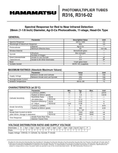
GENERALParameterDescription/ValueUnit Spectral ResponseWavelength of Maximum ResponsePhotocathodeWindow MaterialDynodeDirect Interelectrode Capacitances BaseSuitable Socketnm nm —mm dia.———pF pF ——400 to 1200800Ag-O-Cs 25Borosilicate glass Box-and-grid113.03.514-pin glass base E678-14C (supplied)MaterialMinimum Effective AreaStructureNumber of StagesAnode to Last Dynode Anode to All Other Electrodes PHOTOMULTIPLIER TUBESR316, R316-02MAXIMUM RATINGS (Absolute Maximum Values)Information furnished by HAMAMATSU is believed to be reliable. However, no responsibility is assumed for possible inaccuracies or omissions. Specifications are subject to change without notice. No patent rights are granted to any of the circuits described herein. © 1999 Hamamatsu Photonics K.K.Subject to local technical requirements and regulations, availability of products included in this promotional material may vary. Please consult with our sales office.Supply Voltage: 1250Vdc, K: Cathode, Dy: Dynode, P: AnodeSpectral Response for Red to Near Infrared Detection28mm (1-1/8 Inch) Diameter, Ag-O-Cs Photocathode, 11-stage, Head-On TypeCHARACTERISTICS (at 25°C)VOLTAGE DISTRIBUTION RATIO AND SUPPLY VOLTAGEParameterMin.Unit ParameterValue Unit Supply Voltage Average Anode Current Ambient Temperature15002500.01-80 to +50Vdc Vdc mA °CBetween Anode and Cathode Between Anode and Last DynodeCathode SensitivityAnode SensitivityGainAnode Dark Current at 4A/lm(after 30min. storage in darkness)Time ResponseElectrodes Ratio K Dy11Dy21Dy31Dy41Dy51Dy61Dy71Dy81Dy91111Dy10Dy11P Luminous (2856K)Radiant at 800nm (peak)Red/White Ratio(IR-D80A filter)Quantum Efficiency at 1.06µmLuminous (2856K)Radiant at 800nm (peak)Anode Pulse Rise TimeElectron Transit TimeR316R316-02R316R316-02R316R316-0210————0.045——————201.90.10.140.020.06109505.0 × 105100020001050µA/lm mA/W ——%%A/lm A/W —nA nA ns ns—————————30005000——Typ.Max.PHOTOMULTIPLIER TUBES R316, R316-02Figure 1: Typical Spectral ResponseTPMH1208E02DEC. 1999Figure 2: Typical Gain CharacteristicsTPMHB0504EAFigure 3: Dimensional Outline and Basing Diagram (Unit: mm)TPMHA0016ECTACCA0004EASocket (supplied)(E678-14C)20040060080010001200WAVELENGTH (nm)0.0010.010.1110100C A T H ODE R A D I A N T S E N S I T I V I T Y (m A /W )Q U A N T U M EF F I C I E N C Y (%)SUPPLY VOLTAGE (V)G A I Nat 25°C101102103104105106107500600700800100015001800HAMAMATSU PHOTONICS K.K., Electron Tube Center314-5, Shimokanzo, Toyooka-village, Iwata-gun, Shizuoka-ken, 438-0193, Japan, Telephone: (81)539/62-5248, Fax: (81)539/62-2205U.S.A.: Hamamatsu Corporation: 360 Foothill Road, P. O. Box 6910, Bridgewater. N.J. 08807-0910, U.S.A., Telephone: (1)908-231-0960, Fax: (1)908-231-1218Germany: Hamamatsu Photonics Deutschland GmbH: Arzbergerstr. 10, D-82211 Herrsching am Ammersee, Germany, Telephone: (49)8152-375-0, Fax: (49)8152-2658France: Hamamatsu Photonics France S.A.R.L.: 8, Rue du Saule Trapu, Parc du Moulin de Massy, 91882 Massy Cedex, France, Telephone: (33)1 69 53 71 00, Fax: (33)1 69 53 71 10United Kingdom: Hamamatsu Photonics UK Limited: Lough Point, 2 Gladbeck Way, Windmill Hill, Enfield, Middlesex EN2 7JA, United Kingdom, Telephone: 44(20)8-367-3560, Fax: 44(20)8-367-6384North Europe: Hamamatsu Photonics Norden AB: Smidesvägen 12, SE-171-41 SOLNA, Sweden, Telephone: (46)8-509-031-00, Fax: (46)8-509-031-01Italy: Hamamatsu Photonics Italia: S.R.L.: Strada della Moia, 1/E, 20020 Arese, (Milano), Italy, Telephone: (39)02-935 81 733, Fax: (39)02-935 81 741HOMEPAGE URL SHORT PIN。
SM16JZ47中文资料

· The information contained herein is presented only as a guide for the applications of our products. No responsibility is assumed by TOSHIBA CORPORATION for any infringements of intellectual property or other rights of the third parties which may result from its use. No license is granted by implication or otherwise under any intellectual property or other rights of TOSHIBA CORPORATION or others.
l Isolation Voltage
: VISOL = 1500V AC
Unit: mm
MAXIMUM RATINGS
CHARACTERISTIC
Repetitive Peak Off−State Voltage
SM16GZ47 SM16GZ47A
SM16JZ47 SM16JZ47A
R.M.S On−State Current (Full Sine Waveform Tc = 73°C)
―
300
―
V / µs
―
200
―
(dv / dt) c
VDRM = 400V, Tj = 125°C (di / dt) c = − 8.7A / ms
10
―
―
V / µs
4
―
CB2016T470M中文资料
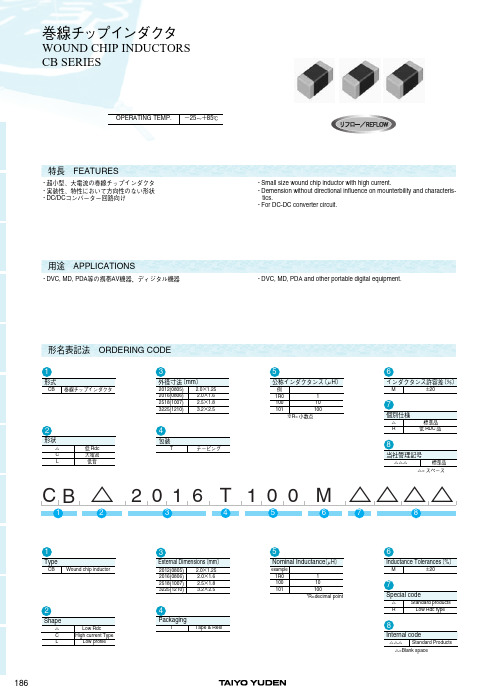
510
0.09
510
0.13
410
0.23
890
0.13
750
0.2பைடு நூலகம்
530
0.33
275
0.66
10 E E E E E E E E E E E E E E E E E E E E E E E E E E E E E E E E E E E E E E E E E E E E E E E E E E E E E E E E E E
1E E E E E E E E E E E E E E E E E E E E E E E E E E E E E E E E E E E E E E E E E E E E E E E E E E E E E E E E E E
1000
0.08
Inductance[AH]
4.7AH
2.2 E E E E E E E E E E E E E E E E E E E E E E E E E E E E E E E E E E E E E E E E E E E E E E E E E E E E E E E E E E
Self-resonant
Ordering code CB CB CB CB CB C2 0 1 6T2 R2M C2 0 1 6T4 R7M C2 0 1 6T1 00M C2 0 1 6T2 20M C2 0 1 6T4 70M
Inductance hAHi 2.2 4.7 10 22 47
Inductance Tolerance
M20%
frequency hMHzi min. 80 45 32 16 11
Measuring frequency hMHzi 7.96
电磁保护设备TeSys GV系列产品参数表说明书
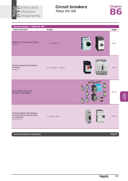
C i r c u i t b r e a k e r sCircuit breakersTeSys GV, GBC ontrol and P rotection C omponentsChapterB60.75g g 1.1g g 1.5375 2.533.5 LR2 K0308GV2LE071.1g g –––––– 2.533.5 LR2 K0308GV2LE071.5g g 1.5g g 3375451 LR2 K0310GV2LE08––– 2.2g g –––451 LR2 K0312GV2LE082.2g g 3501004375 6.378 LR2 K0312GV2LE103g g 410100 5.537510138 LR2 K0314GV2LE144g g 5.510100–––10138 LR2 K0316GV2LE14––––––7.537510138 LRD 14GV2LE14––––––937514170 LRD 16GV2LE165.515507.56751137514170 LR2 K0321GV2LE167.5155096751537518223 LRD 21GV2LE20915401147518.537525327 LRD 22GV2LE2211154015475–––25327 LRD 22GV2LE2215105018.54752237532416LRD 32GV2LE32(1) As % of Icu.g ) > 100 kA.GV2 LE10D F 526144.t i fC i r c u i t b r e a k e r s0.09––––––0.45LRD 03GV2L030.12g g –––0.37g g 0.638LRD 04GV2L040.18g g ––––––0.638LRD 04GV2L04––––––0.55g g 113LRD 05GV2L050.25g g ––––––113LRD 05GV2L05––––––0.75g g 113LRD 06GV2L050.37g g 0.37g g –––113LRD 05GV2L050.55g g 0.55g g 1.1g g 1.622.5LRD 06GV2L06–––0.75g g ––– 1.622.5LRD 06GV2L060.75g g 1.1g g 1.54100 2.533.5LRD 07GV2L07Example: GV3 L32 becomes GV3 L326.(1) As % of Icu. Associated current limiter or fuses, where required. See characteristics page B6/33.g > 100 kA.GV2 L10D F 526145.t i fGV3 L65D F 526146.t i fTeSys GVThermal-magnetic motor circuit breakers GV2 ME0.06gg––––––0.16…0.252.4GV2ME020.09g g––––––0.25…0.405GV2ME030.12 0.18g g g g – –– –– – 0.37 –g–g –0.40…0.638GV2ME040.25gg––– 0.55gg0.63…113GV2ME050.37 0.55 –g g –g g –0.37 0.55 0.75g g g g g g – 0.75 1.1– g g – g g 1…1622.5GV2ME060.75g g1.1gg1.5375 1.6...2.533.5GV2ME071.1 1.5g g g g 1.5 2.2g g g g 2.2 3 3 375 75 2.5 (4)51GV2ME082.2gg350100 43754...6.378GV2ME103 4g g g g 4 5.510 10100 100 5.5 7.5 3 375 756 (10)138GV2ME145.5 –15 –50 –7.5 – 6 –75 – 9 11 3 375 759…14170GV2ME167.5155096751537513…18223GV2ME209154011475 18.537517…23327GV2ME2111154015475 –––20…25327GV2ME22 (3)15105018.54752237524 (32)416GV2ME32Motor circuit breakers from 0.06 to 15 kW / 400 V, with lugsTo order thermal magnetic circuit breakers with connection by lugs, add the digit 6 to the end of reference selected above.Example: GV2 ME08 becomes GV2 ME086.Thermal magnetic circuit breakers GV2 ME with built-in auxiliary contact block With instantaneous auxiliary contact block (composition, see page B6/11):b GV AE1, add suffix AE1TQ to the motor circuit breaker reference selected above. Example: GV2 ME01AE1TQ .b GV AE11, add suffix AE11TQ to the motor circuit breaker reference selected above. Example: GV2 ME01AE11TQ .b GV AN11, add suffix AN11TQ to the motor circuit breaker reference selected above. Example: GV2 ME01AN11TQ .These circuit breakers with built-in contact block are sold in lots of 20 units in a single pack.(1) As % of Icu.(2) The thermal trip setting must be within the range marked on the graduated knob.(3) Maximum rating which can be mounted in enclosures GV2 MC or MP , please consult your Regional Sales Office. g > 100 kA.GV2 ME10D F 526134.t i fC i r c u i t b r e a k e r sTeSys GVTeSys protection componentsThermal-magnetic motor circuit breakers GV2 MEReferences0.06g g ––– 0.16…0.25 2.4GV2ME0230.09g g ––– 0.25…0.405GV2ME0330.120.18g g g g –––0.40…0.638GV2ME0430.250.37g g g g 0.37g g 0.63…113GV2ME0530.370.55g g g g 0.370.550.75g g g g g g 1…1.622.5GV2ME0630.75g g1.1g g 1.6…2.533.5GV2ME0731.11.5g g g g 1.52.2g g g g 2.5…451GV2ME0832.2g g 350100 4…6.378GV2ME10334g g g g 45.510101001006…10138GV2ME1435.515507.5675 9…14170GV2ME1637.515509675 13…18223GV2ME203911151540401147517…23327GV2ME2131115401547520 (25)327GV2ME223Contact blocksDescription Mounting Maximum number Type of contacts Sold in lots of Unitreference Instantaneous auxiliary contactsFront 1N/O + N/C 10GVAE113N/O + N/O 10GVAE203LH side2N/O + N/C 1GVAN113N/O + N/O1GVAN203AccessoryDescriptionApplicationSold in lots of Unitreference Cable end reducerFor connection of conductors from 1 to 1.5 mm 220LA9D99(1) For connection of conductors from 1 to 1.5 mm 2, the use of an LA9 D99 cable end reducer is recommended.(2) Maximum rating which can be mounted in enclosures GV2 MC or MP , please consult your Regional Sales Office (3) The thermal trip setting must be within the range marked on the graduated knob.g > 100 kA.GV2 ME pp 3D F 526135.t i fLA9 D99D F 533898.e p sTeSys GVReferencesTeSys protection componentsThermal-magnetic motor circuit breakersGV2 P, GV3 P and GV3 ME80GV2 P10D F 526137.t i fGV3 P65D F 526139.t i fGV3 P651D F 526140.t i fC i r c u i t b r e a k e r sTeSys GVReferences93610011181001581007.59707010010091150501001001115101010010012…20GV7RS20 2.0109113636100100111518181001001518.58810010015…25GV7RE25 2.0109117070100100111550501001001518.5101010010015…25GV7RS25 2.01018.53610018.522181810010022810025…40GV7RE40 2.01018.57010018.550100221010025…40GV7RS40 2.0102236100301810030810030…50GV7RE50 2.01522701003050100301010030 (50)GV7RS502.01537361004555181810010055810048...80GV7RE80 2.040377010045555050100100551010048...80GV7RS80 2.0404536100–1810075810060...100GV7RE100 2.0404570100–50100751010060...100GV7RS100 2.0405575353510010075903030100100901108810010090 (150)GV7RE1502.020557570701001007590505010010090110101010010090…150GV7RS150 2.02090110353510010011013216030303010010010016020088100100132…220GV7RE220 2.3509011070701001001101321605050501001001001602001010100100132…220GV7RS220 2.350(1) As % of lcu.TeSys protection componentsThermal-magnetic motor circuit breakers GV7 RGV7 RE40D F 526138.t i fGV7 RS220D F 526141.t i f0.12–0.120.180.18–0.370.40…0.6313GV2RT040.090.120.250.370.250.370.370.550.63…122GV2RT050.180.250.370.550.370.550.370.550.750.751.11…1.633GV2RT060.370.750.751.1 1.11.51.6…2.551GV2RT070.550.75 1.11.5 1.51.52.2 2.23 2.5…478GV2RT081.12.22.23344…6.3138GV2RT101.52.234445.5 5.57.56…10200GV2RT142.23 5.55.57.57.59119…14280GV2RT1647.57.5991513…18400GV2RT205.5911111118.517…23400GV2RT21(1) The thermal trip setting must be within the range marked on the graduated knob.GV2 RTD F 526142.t i fC i r c u i t b r e a k e r sblack handle, blue legend plate(1) The thermal trip setting must be within the range marked on the graduated knob.(2) Other accessories such as mounting, cabling and marking accessories are identical to those used for GV2 ME motor circuit breakers, see page B6/13.GV2 RTD F 526142.t i fD F 526340.e p sC i r c u i t b r e a k e r sTeSys GVDescription Mounting Maximum number Type of contacts Sold inlots of Unitreference Instantaneous auxiliary contactsFront (1)1N/O or N/C (2)10GVAE1N/O + N/C 10GVAE11N/O + N/O10GVAE20Side (LH)2N/O + N/C1GVAN11N/O + N/O1GVAN20Fault signalling contact + instantaneous auxiliary contact Side (3) (LH)1N/O (fault)+ N/O1GVAD1010+ N/C1GVAD1001N/C (fault)+ N/O1GVAD0110+ N/C1GVAD0101Short-circuit signalling contactSide (LH)1C/O common point1GVAM11(1 block on RH sideof circuit breaker GV2 ME)50 Hz GVAX11560 Hz GVAX116127 V60 Hz GVAX115220…240 V 50 Hz GVAX22560 Hz GVAX226380…400 V50 Hz GVAX38560 Hz GVAX386415…440 V 50 Hz GVAX415440 V60 Hz GVAX385Add-on contact blocksDescriptionMountingMaximum number Reference Visible isolation block (5)Front (1)1GV2AK00 (6)LimitersAt top(GV2 ME and GV2 P)1GV1L3Independent1LA9LB920(1) Mounting of a GV AE contact block or a GV2 AK00 visible isolation block on GV2 P and GV2 L .(2) Choice of N/C or N/O contact operation, depending on which way round the reversible block is mounted.(3) The GV AD is always mounted next to the circuit breaker.(4) To order an undervoltage trip: replace the dot (p ) in the reference with a U , example: GV AU025. To order a shunt trip: replace the dot (p ) in the reference with an S , example: GV AS025.(5) Visible isolation of the 3 poles upstream of circuit breaker GV2 P and GV2 L .Visible isolation block GV2 AK00 cannot be used with motor circuit breakers GV2 P32 and GV2 L32 (Ith max = 25 A).(6) Ie Max = 32 A.ReferencesTeSys protection componentsThermal-magnetic and magnetic motor circuit breakers GV2 with screw clamp connectionsAdd-on blocks and accessoriesCharacteristics:pages B6/89 and B6/94Dimensions, schemes:pages B6/70 to B6/82LA9LB920D B 126629.e p sC i r c u i t b r e a k e r sTeSys GVTerminal blockfor supply to one or more GV2 G busbar setsConnection from the top1GV1G09Can be fitted with current limiter GV1 L3 (GV2 ME and GV2 P)1GV2G05Cover for terminal block For mounting in modular panels10LA9E07Flexible 3-pole connection for connecting a GV2 to a contactor LC1-D09…D25 Centre distance between mounting rails: 100…120 mm10GV1G02Set of connections upstream/downstream For connecting GV2 ME to a printed circuit board 10GV2GA01“Large Spacing” adapter UL 508 type EFor GV2 P pp H7 (except 32 A)1GV2GH7Clip-in marker holders (supplied with each circuit breaker)For GV2 P , GV2 L, GV2 LE and GV2 RT (8 x 22 mm)100LA9D92ReferencesTeSys protection componentsThermal-magnetic and magnetic motor circuit breakers GV2 with screw clamp connectionsAccessoriesDimensions, schemes:pages B6/70 to B6/82D B 417942.e p sTeSys GVD B 126631.e p sD B 126630.e p sD B 126632.e p s7P B 106297_45.e p sExtended Rotary HandleAllows a circuit breaker or a starter-controller installed in back of an enclosure to be operated from the front of the enclosure.A rotary handle can be black or red/yellow, IP54 or IP65. It includes a function for locking the circuit breaker or the starter in the O (Off) or I (On) position(depending of the type of rotary handle) by means of up to 3 padlocks with a shank diameter of 4 to 8 mm. The extended shaft must be adjusted to use in different size enclosures. The IP54 rotary handle is fixed with a nut (Ø22) to make easierthe assembling. The new Laser Square tool brings the accuracy to align the circuit breaker and the rotary handle.device(padlocks not included)ReferencesTeSys protection componentsThermal-magnetic and magnetic motor circuit breakers GV2 with screw clamp connectionsC i r c u i t b r e a k e r sTeSys GVDescriptionMounting Maximum number Type of contacts Sold inlots of Unitreference Instantaneous auxiliary contactsFront1N/O or N/C (1)10GVAE1N/O + N/C 10GVAE11 (2)N/O + N/O10GVAE20 (2)Side (LH)2N/O + N/C1GVAN11 (2)N/O + N/O1GVAN20 (2)Fault signalling contact + instantaneous auxiliary contactFront 1N/O (fault)+ N/O1GVAED101 (2)N/O (fault)+ N/C1GVAED011 (2)Side (3) (LH)1N/O (fault)+ N/O1GVAD1010+ N/C1GVAD1001N/C (fault)+ N/O1GVAD0110+ N/C1GVAD0101Short-circuit signalling contact Side (LH)1C/O common point 1GVAM11(4)MountingVoltage ReferenceSide(1 block on RH side of circuit breaker)24 V 50 Hz GVA p 02560 Hz GVA p 02648 V 50 Hz GVA p 05560 Hz GVA p 05610050 Hz GVA p 107100…110 V 60 Hz GVA p 107110…115 V 50 Hz GVA p 11560 Hz GVA p 116120…127 V 50 Hz GVA p 125127 V 60 Hz GVA p 115200 V50 Hz GVA p 207200…220 V 60 Hz GVA p 207220…240 V 50 Hz GVA p 22560 Hz GVA p 226380…400 V 50 Hz GVA p 38560 Hz GVA p 386415…440 V 50 Hz GVA p 415415 V 60 Hz GVA p 416440 V 60 Hz GVA p 385480 V 60 Hz GVA p 415500 V 50 Hz GVA p 505600 V60 HzGVA p 505AccessoriesDescription Reference Sets of 3-pole 115 A busbars Pitch: 64 mm2 tap-off GV3 P pp and GV3 L pp GV3G2643 tap-off GV3 P pp and GV3 L pp GV3G364Cover “Large Spacing” UL 508 type E (Only one cover required on supply side)GV3 P ppGV3G66(1) Choice of N/C or N/O contact operation, depending on which way round the reversible block is mounted.(2) Contact blocks available in version with spring terminal connections. Add a figure 3 at the end of the references selected above. Example: GV AED101 becomes GV AED1013.(3) The GV AD pp is always mounted next to the circuit breaker.(4) To order an undervoltage trip: replace the dot (p ) in the reference with a U , example: GV AU025. To order a shunt trip: replace the dot (p ) in the reference with an S , example: GV AS025.Add-on blocks and accessoriesGV3 G66D F 537424.e p sTeSys GVD B 126637.e p sD B 126636.e p sD B 126632.e p s7P B 106297_45.e p sExtended Rotary HandleAllows a circuit breaker or a starter-controller installed in back of an enclosure to be operated from the front of the enclosure.A rotary handle can be black or red/yellow, IP54 or IP65. It includes a function for locking the circuit breaker or the starter in the O (Off) or I (On) position(depending of the type of rotary handle) by means of up to 3 padlocks with a shank diameter of 4 to 8 mm. The extended shaft must be adjusted to use in different size enclosures. The IP54 rotary handle is fixed with a nut (Ø22) to make easierthe assembling. The new Laser Square tool brings the accurency to align the circuit breaker and the rotary handle.For English 10-GVAPSEN For German 10-GVAPSDE For Spanish10-GVAPSES For Chinese 10-GVAPSCN For Portuguese 10-GVAPSPT For Russian 10-GVAPSRU For Italian10-GVAPSITD F 526342.e p sB6/21C i r c u i t b r e a k e r sTeSys GVfor locking the Start button (on open-mounted product)using up to 3 padlocks(padlocks to be ordered separately)External operator for mounting on enclosure door.Red Ø40 knob on yellow plate, padlockable in position O (with up to 3 padlocks). Door locked when knob in position I, and when knob padlocked in position O.GK3AP03(1) 1 voltage trip OR 1 fault signalling contact to be fitted inside the motor circuit breaker.Other versions24 to 690 V, 50 or 60 Hz voltage trips for circuit breakers GV3 ME80.Please consult your Regional Sales Office.ReferencesTeSys protection componentsMotor circuit breakers GV3 ME80 and GK3 EF80Add-on blocks and accessoriesCharacteristics:pages B6/89 and B6/92Dimensions:page B6/47B6/22D F 526344.e p sB6/23C i r c u i t b r e a k e r sTeSys GVThese allow remote indication of the circuit breaker contact states. They can be used for signalling, electrical locking, relaying, etc. They are available in two versions: standard and low level. They include a terminal block and the auxiliary circuits leave the circuit breaker through a hole provided for this purpose.They perform the following functions, depending on where they are located in the circuit breaker:Low levelGV7AB11Fault discrimination devicesThese make it possible to:b either differentiate a thermal fault from a magnetic fault,b or open the contactor only in the event of a thermal fault.VoltageReference a 24...48 and c 24…72 V GV7AD111 (1)z 110…240 VGV7AD112 (1)Electric tripsThese allow the circuit breaker to be tripped via an electrical control signal.b Undervoltage trip GV7 AUv Trips the circuit breaker when the control voltage drops below the tripping threshold, which is between 0.35 and 0.7 times the rated voltage.v Circuit breaker closing is only possible if the voltage exceeds 0.85 times the rated voltage. Circuit breaker tripping by a GV7 AU trip meets the requirements of IEC 60947-2.b Shunt trip GV7 ASTrips the circuit breaker when the control voltage rises above 0.7 times the rated voltage.b Operation (GV7 AU or GV7 AS)v When the circuit breaker has been tripped by a GV7 AU or AS, it must be reset either locally or by remote control. (For remote control, please consult your Regional Sales Office).v Tripping has priority over manual closing: if a tripping instruction is present, manual action does not result in closing, even temporarily, of the contacts.v Durability: 50 % of the mechanical durability of the circuit breaker.TypeVoltageReference Undervoltage trip48 V, 50/60 HzGV7AU055 (1)110…130 V, 50/60 Hz GV7AU107 (1)200…240 V, 50/60 Hz GV7AU207 (1)380…440 V, 50/60 Hz GV7AU387 (1)525 V, 50 HzGV7AU525 (1)Shunt trip48 V, 50/60 HzGV7AS055 (1)110…130 V, 50/60 Hz GV7AS107 (1)200…240 V, 50/60 Hz GV7AS207 (1)380…440 V, 50/60 Hz GV7AS387 (1)525 V, 50 HzGV7AS525 (1)(1) For mounting of a GV7 AD or a GV7 AU or AS.ReferencesTeSys protection componentsThermal-magnetic motor circuit breakers GV7 R with screw clamp connectionsAdd-on blocks and accessoriesCharacteristics:pages B6/51, B6/52 and B6/56Dimensions:pages B6/79 to B6/81Schemes:page B6/83B6/24B6/25C i r c u i t b r e a k e r sTeSys GVDescription ApplicationFor use on contactors Sold in lots of Unitreference Clip-on connectors for GV7 RUp to 150 A, 1.5…95 mm 2–3GV7AC021Up to 220 A, 1.5…185 mm 2–3GV7AC022Spreader 3-pole (1)To increase the pitch to 45 mm–1GV7AC03Terminal shields IP 405 (1)Supplied with sealing accessory–1GV7AC01Phase barriersSafety accessories used when fitting of shields is impossible –2GV7AC04Insulating screens Ensure insulation between the connections and the backplate –2GV7AC05Kits for combination with contactor (2)Allowing link between thecircuit breaker and the contactor. The cover provides protection against direct finger contactLC1 F115…F1851GV7AC06LC1 F225 and F2651GV7AC07LC1 D115 and D1501GV7AC08Replaces the circuit breaker front cover; secured by screws. It includes a device for locking the circuit breaker in the O (Off) position by means of up to 3 padlocks with a shank diameter of 5 to 8 mm (padlocks not included). A conversion accessory allows the direct rotary handle to be mounted on the enclosure door. In this case, the door cannot be opened if the circuit breaker is in the “ON” position. Circuit breaker closing is inhibited if the enclosure door is open.Description TypeDegree of protection Reference Direct rotary handleBlack handle, black legend plate IP 40GV7AP03Red handle, yellow legend plateIP 40GV7AP04Adapter plate (3)Four mounting direct rotary handle on enclosure doorIP 43GV7AP05Allows a circuit breaker installed in the back of an enclosure to be operated from the front of the enclosure. It comprises:b a unit which screws onto the front cover of the circuit breaker,b an assembly (handle and front plate) to be fitted on the enclosure door,b an extension shaft which must be adjusted (distance between the mounting surface and the door: 185 mm minimum, 600 mm maximum). It includes a device for locking the circuit breaker in the O (Off) position by means of up to 3 padlocks with a shank diameter of 5 to 8 mm (padlocks not included). This prevents the enclosure door from being opened.DescriptionTypeDegree of protection Reference Extended rotary handleBlack handle, black legend plate IP 55GV7AP01Red handle, yellow legend plateIP 55GV7AP02Allows circuit breakers not fitted with a rotary handle to be locked in the O (Off) position by means of up to 3 padlocks with a shank diameter of 5 to 8 mm (padlocks not included).Description ApplicationReference Locking deviceFor circuit breaker not fitted with a rotary handleGV7V01(1) Terminal shields cannot be used together with spreaders.(2) The kit comprises links, a protective shield and a depth adjustable metal bracket for the breaker.(3) This conversion accessory makes it impossible to open the door if the device is closed and prevents the device from being closed if the door is open.ReferencesTeSys protection componentsThermal-magnetic motor circuit breakers GV7 R with screw clamp connectionsAccessoriesGV7 AC07D F 537429.e p sGV7 AC08D F 537428.e p sDimensions:pages B6/79 to B6/81B6/260.5 6.63GB2DB051143GB2DB062263GB2DB073403GB2DB084503GB2DB095663GB2DB106833GB2DB1281083GB2DB14101383GB2DB16121653GB2DB20162203GB2DB21202703GB2DB22(1) Conforming to IEC 60947-1.GB2 CBppD F 526243.t i fGB2 CD ppD F 526244.t i fGB2 DBppD F 526245.t i fPresentation, selection :page B6/84Characteristics :pages B6/85 to B6/87Dimensions :page B6/88Schemes :page B6/88B6/27C i r c u i t b r e a k e r s(1) Conforming to IEC 60947-1.Accessories for circuit breakers GB2-CB, DB and CSDescriptionSold in lots of Unitreference Busbar set for supply to 10 GB2 DB or20 GB2 CB or GB2 CS with 2 connectors1GB2G210Supply connector 10GB2G01GB2 CS ppD F 526246.t i fPresentation, selection :page B6/84Characteristics :pages B6/85 to B6/87Dimensions :page B6/88Schemes :page B6/88B6/28B6/29B6/30TeSys GVCharacteristicsTeSys protection componentsMagnetic motor circuit breakers GV2 LE and GV2 LReferences:pages B6/2 and B6/3Dimensions:pages B6/43 to B6/47Schemes:page B6/48add-on contact blocks. Side by side mounting is possible up to 40 °C.(2) When mounting on a vertical rail, fit a stop to prevent any slippage.(1) As % of Icu.Average operating times at 20 °C related to multiples of the setting currentD F 534092.e p s1 3 poles from cold state2 2 poles from cold state3 3 poles from hot stateDynamic stressI peak = f (prospective Isc) at 1.05 Ue = 435 VD F 534093.e p s1 Maximum peak current2 32 A3 25 A4 18 A5 14 A6 10 A7 6.3 A8 4 A9 2.5 A 10 1.6 A11 Limit of rated ultimate breaking capacity on short-circuit of GV2 LE (14, 18, 23 and 25 A ratings).Dynamic stressI peak = f (prospective Isc) at 1.05 Ue = 435 VD F 534094.e p s1 Maximum peak current2 32 A3 25 A4 18 A5 14 A6 10 A7 6.3 A8 4 A9 2.5 A 10 1.6 A11 Limit of rated ultimate breaking capacity on short-circuit of GV2 LE (14, 18, 23 and 25 A ratings).Thermal limit in kA 2s in the magnetic operating zone Sum of I 2dt = f (prospective Isc) at 1.05 Ue = 435 V22Prospective Isc (kA)D F 534095.e p s1 32 A 2 25 A3 18 A4 14 A5 10 A6 6.3 A7 4 A8 2.5 A9 1.6 AThermal limit in kA 2s in the magnetic operating zone Sum of I 2dt = f (prospective Isc) at 1.05 Ue = 435 V22D F 534096.e p s1 25 A and 32 A 2 18 A3 14 A 4 10 A5 6.3 A6 4 A7 2.5 A8 1.6 AThermal limit in kA 2s in the magnetic operating zone Sum of I 2dt = f (prospective Isc) at 1.05 Ue = 435 V22D F 534097.e p s1 32 A (GV2 LE32)2 25 A and 32 A (GV2 L32)3 18 A4 14 A5 10 A6 6.3 A7 4 A8 2.5 A9 1.6 A10 Limit of rated ultimate breaking capacity on short-circuit of GV2 LE (14, 18, 23 and 25 A ratings).Average operating time at 20 °C without prior current flowx the setting current (Ir)D F 534098.e p s1 3 poles from cold state2 2 poles from cold state3 3 poles from hot stateA Thermal overload relay protection zoneB GV3 L protection zoneDynamic stressI peak = f (prospective Isc) at 1.05 Ue = 435 VProspective Isc (kA)D B 418280.e p s1 Maximum peak current2 GV3 L653 GV3 L504 GV3 L405 GV3 L326 GV3 L25Thermal limit in A 2sSum of I 2dt = f (prospective Isc) at 1.05 Ue = 435 V2Prospective Isc (kA)D B 418279.e p s1 GV3 L652 GV3 L503 GV3 L404 GV3 L325 GV3 L25TeSys GVDimensions, mountingD F 537440.e p sD F 537441.e p sD F 537444.e p sTeSys protection componentsMagnetic motor circuit breakers GV2 L and GV2 LETeSys GVDimensions, mounting TeSys protection componentsMagnetic motor circuit breakers GV2 L and GV2 LED B 127415.e p sD B 127414.e p sa b Mini Maxi Mini Maxi GV2 APN pp140250GV2 APN pp + GV APH02151250GV2 APN pp + GV APK11250434--GV2 APN pp + GV APH02 + GV APK11--250445TeSys GVDimensions,mounting Sets of busbars GV2 G445, GV2 G454, GV2 G472, with terminal block GV2 G05D F 537451.e p sGV2 G445224269314359GV2 G454260314368422GV2 G472332404476548D F 537452.e p sD F 537454.e p sGV2 G345 (3 x 45 mm)134GV2 G354 (3 x 54 mm)152TeSys protection componentsMagnetic motor circuit breakers GV2 L and GV2 LED F 537480.e psD F 537435.e p sD F 510637.e p sD F 510638.e p sD B 127416.e p sD B 127417.e p sa b Mini Maxi Mini Maxi GV3 APN pp189300--GV3 APN pp + GV APK12300481GV3 APN pp + GV APH03--200300GV3 APN pp + GV APH03 + GV APK12--300492TeSys GVSchemesTeSys protection componentsMagnetic motor circuit breakers GV2 L, GV2 LE, GV3 LD F 537474.e p sD F 537475.e p sD F 537476.e p sGV2 ME, GV2 P , GV3 ME, GV3 P and GV7 R motor circuit breakers are 3-pole thermal-magnetic circuit breakers specifically designed for the control and protection of motors , conforming to standards IEC 60947-2 and IEC 60947-4-1.Connection GV2GV2 ME and GV2 P circuit breakers are designed for connection by screw clamp terminals.Circuit breaker GV2 ME can be supplied with lugs or spring terminal connections.Spring terminal connections ensure secure, permanent and durable clamping that is resistant to harsh environments, vibration and impact and are even more effective when conductors without cable ends are used. Each connection can take two independent conductors.GV3GV3 circuit breakers feature connection by BTR screws (hexagon socket head), tightened using a n° 4 Allen key.This type of connection uses the Ever Link ® system with creep compensation (1) (Schneider Electric patent).This technique makes it possible to achieve accurate and durable tightening torque, in order to avoid cable creep.GV3 circuit breakers are also available with connection by lugs. This type of connection meets the requirements of certain Asian markets and is suitable for applications subject to strong vibration, such as railway transport.GV7GV7 circuit breakers: with connection by screw clamp terminals (for bars and lugs) and by clip-on connectors.OperationControl is manual and local when the motor circuit breaker is used on its own.Control is automatic and remote when it is associated with a contactor.GV2 ME and GV3 ME80Pushbutton control.Energisation is controlled manually by operating the Start button “I” 1.De-energisation is controlled manually by operating the Stop button “O” 2, or automatically by the thermal-magnetic protection elements or by a voltage trip attachment.GV2 P , GV3 P and GV7 Rb Control by rotary knob: for GV2 P and GV3 P b Control by rocker lever: for GV7 R.Energisation is controlled manually by moving the knob or rocker lever to position “I” 1.De-energisation is controlled manually by moving the knob or rocker lever to position “O” 2.De-energisation due to a fault automatically places the knob or rocker lever in the “Trip” position 3.Re-energisation is possible only after having returned the knob or rocker lever to position “O”.(1) Creep: normal crushing phenomenon of copper conductors, that is accentuated over time.GV2 MEwith screw clamp terminals124D F 526134.t i fGV2 MEwith spring terminals connections124D F 526135.t i fGV3 P1324D F 526136.t ifGV2 P1342D F 526137.t i fGV7 R132D F 526138.t i f。
RC-2409D中文资料
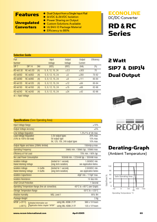
Derating-Graph
(Ambient Temperature)
100 80 60 40 20 0 -40 0 50 100 150
40pF min. / 115pF max. 10 GΩ min. 1 Second -40°C to +85°C (see Graph) -55°C to +125°C 95% RH 2.8g 988 x 103 hours 135 x 103 hours
19.90 7.10 3.25 2.0 15.24
10.00
Dual Output RECOM RC-0505D ****
7.70
Recommended Footprint Details
ø 0.51 typ.
1 14
Pin Connections Pin # 1 7 8 9 11 RC –Vin NC Com +Vout –Vout +Vin
80%
100%
66
April-2005ຫໍສະໝຸດ 器件交易网ECONOLINE
DC/DC-Converter
Package Style and Pinning (mm)
RD & RC Series
3rd angle projection
7 PIN SIP Package
7.05 10.20
RECOM RD-xxxxD ****
Dual Output RECOM RD-0505D ****
0.51 typ.
4.10
0.51 typ.
1 2
4 5 6
Recommended Footprint Details
瑞萨MCU型号速查手册

SSOP-20 SOP-20
家电、OA设备、民用设备
M34508G4H-XXXFP/GP
○○
4509
M34509G4FP M34509G4-XXXFP
M34509G4HFP M34509G4H-XXXFP
--
4096W
256W
6MHz/ 1.8V~5.6V
0.5us @6MHz
18 - - ○ -
10位×6
M37546G4GP/HP/SP M37546G4-XXXGP/HP/SP
8K 16K
384
8MHz/ 1.8~5.5V
0.25us @8MHz
25 - - ○ ○ ○ ○ 10位×6
-
2 2 ○ ○ ○ ○ - - ○ ○ ○ - - 12 -20~85
512
SDIP-32 LQFP-32
WQFN-36
2K
60K
2.5K
照相机、音频设备、家电、民用设备
3850A
M38503G4AFP/SP M38503G4A-XXXFP/SP
16K
512
12.5MHz/ 1.8~5.5V
0.32us @12.5MHz
34
-
○
-
-
-
-
10位×9
-
4 - - - ○ ○ - - ○ ○ ○ - - 6 -20~85
SDIP-42 SSOP-42
75
芯片封装说明
78
QzROM
720、740工具
低功耗
R8C族及工具
M16C
R32C
M16C族工具 SuperH族及工具 安全MCU
78K
V850
78K、V850工具 芯片封装说明
RCD16-47B6RL资料
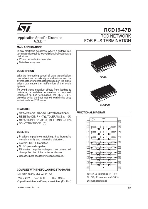
RCD16-47B®October 1998-Ed :2ANETWORK OF 16R-C-D LINETERMINATIONS RESISTANCE :R =47 Ω,TOLERANCE +/-10%CAPACITANCE:C =33pF,TOLERANCE+/-10%SCHOTTKY DIODE :(D)FEATURESIn any electronic equipment where a suitable bus terminationis requiredto avoidsignalreflectionsand distortions :PC and workstation computer Data-line analyzers MAIN APPLICATIONSFUNCTIONAL DIAGRAMDESCRIPTIONWith the increasing speed of data transmission,line reflections provide signal distorsions and the overshootsor undershootsproduced on the signal edges can cause the malfunction of the whole system.To avoid these negative effects from leading to problems,a suitable termination is required.Dedicated to bus termination,the RCD16-47B provides by far the best method to minimise stray emissions from PCB tracks.RCD NETWORKFOR BUS TERMINATIONApplication Specific DiscretesA.S.D.TMProvides impedance matching,thus increasing noise immunity and minimizing distortion.Lowers EMI /RFI radiation.No DC power dissipation.Eliminates negative voltages :no current will change the bias of the protected es the best of all termination schemes.BENEFITSMIL STD 883C -Method 3015-6-V PP =2kVC=100pF R =1500Ω-3positive strikes and 3negativestrikes (F=1Hz)COMPLIESWITH THE FOLLOWINGSTANDARDS:SO20SSOP202019181716151413121112345678109R =47 Ω,tolerance +/− 10 %C =33pF,tolerance +/-10%D =Schottky diode1/7RCD16-47BAPPLICATION NOTE:BUS TERMINATIONWith the increasing speed of data transmission(PC,TV,...),engineersare naturallyconfrontedwith effects that were of less significance with slower circuits.Among these are the effects described in transmission line theory:line reflections provide signal distortions and the overshoots or undershootsproduced on the signal edges can finally cause the malfunction of the whole system.1.Reflection at a non terminated lineThe figure below shows the circuit of a transmission system in which a memory device(input impedance of 100kΩ)is connectedat the end of a line with line impedance Zo.10Ω100kΩIf this line is not properly terminated,a certain amount of the energy is reflected back,inducing a reflection phenomenathat can distort the signal.This can result in improper operation of the system.The simulation shown on the above figure illustrates the signal distortion producedby line reflection at the end of the line which is not well terminated.Even if the signal at the start of the line has the correctform(upper curve),considerable distortion arises at the end of the line(lower curve).On the positive edge,the overshoot can exceed the maximum operating voltage of the used circuit technologywhich will then be destroyed.Also,the following negativeundershoot may reach a level low enough to change the value of the logic state.If it affectsof an addressline,a wrong memory cell will be addressed,and in the case of a data line,the data can be corrupted.This phenomenaalso occurs on the falling edge.To avoid these negative effects from leading to problems in a system,a suitable termination is required.2/7RCD16-47B2.The RCD terminationThe traditional solution to properly match each line of the bus consists of the use of several discrete resistances,capacitorsand small schottky diodes.For a16-bit bus,this requires48discrete components.SGS-THOMSON offers an innovating solution with a monolithic structure using ASD TM technology(*). The ASD TM technologyenables to integrate monolithically16of these RCD”basic cells”onto a single chip device.The RCD16-47B reduces component cost and assembly cost,saves board space and improves reliability.The simulation illustrates the signal distortion produced by line reflection at the end of the line when such a termination is used.The resistor provides the path termination for PCB track,thus resulting in low reflection phenomen a. The capacitor of33pF blocks DC currents while acting as a short circuit during signal transitions,and holds the bus at the last logic level.It reduces power consumption and avoids excessive current.The small Schottkydiode clamps the negative remaining undershoots which can result from impedance mismatch.This damps negative voltages and prevents the logic signal from rising above the logic level ’0’threshold after a falling edge.The RCD termination provides optimal solution compared to all other termination techniques.(*)ASD™=Apllicaion Specific Discretes.3/7Symbol Parameter and test conditionsTyp.Max.Unit R C Connection resistance (note1)T amb =25°C0.25ΩC t Total capacitance F =1MHz,V R =0V,V RMS =30mV45pF I R Leakage current V R =V RRM T j =25°C T j =70°C 110µA V FForward voltageI F =1mA I F =16mAT j =25°C T j =25°C0.51VNote 1:Rc is the resistance between pin 1and pin 11or between pin 10and pin 20ELECTRICAL CHARACTERISTICS Symbol ParameterValue Unit P Total power dissipation per package500mW I F Continuous forward current per Schottkydiode 50mA V RRM Repetitive peak reverse voltage 7.5V V PP Maximum electrostatic discharge MIL STD 883C -METHOD 3015-62kV T stg T jStorage temperature range Maximum junction temperature-55to +150150°C °CABSOLUTE MAXIMUM RATINGS (0°C ≤T amb ≤70°C)Symbol ParameterPackage Value Unit R th(j-a)Junction to ambientSO20SSOP20100140°C/WTHERMAL RESISTANCE RCD16-47B4/7PSPICE MODEL per RCD CELLLR13ΩR39ΩR247ΩC133pFCvarCvarDschot3nH SO201.75nH SSOP20tDschot parameters Cvar parametersZ magnitude versus frequencyPhase versus frequencyΩ°SO20PackageSSOP 20PackageΩZ magnitude versus frequency°Phase versus frequencyRCD16-47B5/7ORDER CODER C D16-47B RLProduct16cellsR =47ΩPackaging::tubeRL :tape &reelpackage :B =SO20B6=SSOP20Product PackageBase QtyTubeTape &reelRCD16-47B SO20401000RCD16-47B6SSOP20662000Type Package Marking RCD16-47B SO20RCD1647B RCD1647B6SSOP20RCD1647B6Packging :Preferred packaging is tape and reel.MARKINGRCD16-47B6/7SSOP20(Plastic)LEkbeA1110120DE1A 2A1cInformation furnished is believed to be accurate and reliable.However,STMicroelectronics assumes no responsibility for the consequences of use of such information nor for any infringementof patents or other rights of third parties which may result from its use.No license is granted by implication or otherwise under any patent or patent rights of STMicroelectronics.Specifications mentioned in this publication are subject to change without notice.This publication supersedes and replaces all information previously supplied.STMicroelectronics products are not authorized for use as critical components in life support devices or systems without express written ap-proval of STMicroelectronics.The ST logo is a registered trademark of STMicroelectronics ©1998STMicroelectronics -Printed in Italy -All rights reserved.STMicroelectronics GROUP OF COMPANIESAustralia -Brazil -Canada -China -France -Germany -Italy -Japan -Korea -Malaysia -Malta -Mexico -Morocco -The Netherlands -Singapore -Spain -Sweden -Switzerland -Taiwan -Thailand -United Kingdom -U.S.A.Khx45°CL AA1BeDE HREF.DIMENSIONSMillimeters InchesMin.Typ.Max.Min.Typ.Max.A 2.000.079A10.250.010A2 1.51 2.000.0590.079b 0.250.300.350.0100.0120.014c 0.100.350.0040.014D 7.058.050.2780.317E 7.608.700.2990.343E1 5.02 6.10 6.220.1980.2400.245e 0.650.026k 0°10°0°10°L0.250.500.800.0100.0200.031PACKAGE MECHANICAL DATA SO20(Plastic)REF.DIMENSIONSMillimeters InchesMin.Typ.Max.Min.Typ.Max.A 2.35 2.650.0920.104A10.100.200.0040.008B 0.330.510.0130.020C 0.230.320.0090.013D 12.613.00.4840.512E 7.407.600.2910.299e 1.270.050H 10.010.650.3940.419h 0.250.750.0100.029L 0.501.270.0200.050K8°(max)RCD16-47B7/7。
智能家电常用数字信号采样转换IC电路简介(二)

智能家电常用数字信号采样转换IC电路简介(二)
景曙光
【期刊名称】《家电维修》
【年(卷),期】2022()4
【摘要】(上接3期)7.CH376S文件管理控制芯片CH376S是文件管理控制芯片,用于单片机系统读写U盘或SD卡中的文件,其引脚功能见表4。
该芯片内置USB 通讯协议和处理Mass-Storage海量存储设备的专用通讯协议的基本固件,以及SD 卡的通讯接口固件,FAT 16、FAT32和FAT12文件系统的管理固件,支持USB设备方式和USB主机方式,即支持常用的USB存储设备(包括U盘、USB硬盘、USB 闪存盘、USB读卡器)和SD卡(包括标准容量SD卡、高容量HC-SD卡和与协议兼容的MMC卡和TF卡),其典型应用电路如图9所示。
【总页数】4页(P8-11)
【作者】景曙光
【作者单位】不详
【正文语种】中文
【中图分类】TP3
【相关文献】
1.《建设事业集成电路(IC)卡应用技术》、《建设事业集成电路(IC)卡产品检测》标准修订、制订情况简介
2.智能家电常用新型传感器电路原理精讲(上)
3.智能家电
常用新型传感器电路原理精讲(中)4.智能家电常用数字信号采样转换IC电路简介(三)5.智能家电常用数字信号采样转换IC电路简介(一)
因版权原因,仅展示原文概要,查看原文内容请购买。
74HC165中文资料-数据手册-参数
74HC165中文资料数据手册参数一、74HC165简介1. 工作电压范围宽:2.0V至6.0V;2. 工作频率高:最高可达50MHz;3. 低功耗:静态功耗几乎为零;4. 输入输出兼容TTL电平;5. 封装形式多样:DIP、SOIC、TSSOP等。
二、74HC165参数1. 电源电压(VCC):2.0V至6.0V;2. 输入电压(VIN):0V至VCC;3. 输出电压(VOUT):0V至VCC;4. 工作温度范围:40℃至+125℃;5. 最大输入电流(II):±1μA;6. 最大输出电流(IO):±25mA;7. 最大功耗(PD):500mW(TA=25℃);8. 传输延迟时间(tpd):22ns(典型值,VCC=5V);9. 输入上升时间(tr):20ns(典型值,VCC=5V);10. 输入下降时间(tf):20ns(典型值,VCC=5V);11. 输出上升时间(tr):25ns(典型值,VCC=5V);12. 输出下降时间(tf):25ns(典型值,VCC=5V)。
三、74HC165引脚功能1. AH(输入端):8位并行数据输入端;2. SH/LD(移位/装载控制端):高电平时,数据从输入端AH并行装载到寄存器;低电平时,数据从输入端A串行移位进入寄存器;3. CLK(时钟输入端):上升沿触发,用于控制数据的移位和装载;4. SER(串行输入端):串行数据输入端,用于接收外部串行数据;5. QH'(串行输出端):串行数据输出端,输出最高位;6. GND(地):电源地;7. VCC(电源):正电源输入。
四、74HC165应用电路1. 数据串行化:将并行数据转换为串行数据,以便于通过单线或少量线进行传输。
2. 数据扩展:通过级联多个74HC165,实现数据位数的扩展,增加并行数据的宽度。
3. 数据缓冲:作为数据缓冲器,提高系统的驱动能力。
【电路图】将74HC165的AH端连接至并行数据源;SH/LD端接高电平,使能并行数据装载;CLK端接时钟信号,控制数据装载和移位;SER端接下一级74HC165的QH'端,实现级联;QH'端输出串行数据至下一级处理或传输。
关于环境温度对RCD剩余电流动作特性的影响分析
关于环境温度对RCD剩余电流动作特性的影响分析发布时间:2021-07-26T16:10:54.327Z 来源:《基层建设》2021年第13期作者:徐献[导读] 摘要:RCD在低压电网当中应用广泛,可以为保障电网运行安全提供保障。
广州市稳建工程检测有限公司 510000摘要:RCD在低压电网当中应用广泛,可以为保障电网运行安全提供保障。
剩余电流可以为RCD提供动作信号,使该装置发挥剩余电流保护作用。
基于此,本文着眼于RCD剩余电流动作,对环境温度变化下的RCD剩余电流动作特性进行分析,从推动装置有效使用的角度出发对环境温度带来的影响进行论述,希望能为相关工作人员带来参考。
关键词:环境温度;RCD;剩余电流;变温试验前言:RCD的运行影响因素较多,其中产生重要作用的是环境温度。
RCD剩余电流动作特性,极容易随环境温度变化而变化。
因此,研究环境温度对RCD剩余电流动作特性的影响十分必要。
在实践工作当中,相关工作人员应该从RCD装置质量检测和运行保障等角度出发,分析环境温度对剩余电流动作特性的影响。
1RCD基本情况概述RCD全称Residual Current Device,中文名称为剩余电流动作保护器。
这种装置可用于检测电路回路剩余电流量,更能基于剩余电流值实现主电路接通或断开,是一种十分常见的漏电保护装置。
在实际应用时,RCD可以通过切断用电回路预防电气火灾、电气设备损坏,还能防止触电[1]。
RCD装置的运行原理是,电气设备漏电后电气回路中出现剩余电流,RCD检测到剩余电流后获得动作信号,通过启闭开关切断电源,从而实施漏电保护。
2RCD剩余电流动作特性的变温试验提高RCD装置的运行可靠性,是增强电气设备和电网漏电保护质量的有效方法。
在这一过程中,相关工作人员应该从质量检测的角度出发,着力提升RCD装置的运行质量和能力。
从实际应用情况来看,分立元件式RCD运行状态十分容易受到环境温度影响,为了确定环境温度的影响力以及RCD运行稳定性,质量检测人员应该开展试验。
uc3846中文资料
UC3846/47电流模式PWM控制器特点和引脚说明1.特点(1)自动前馈补偿。
(2)可编程控制的逐个脉冲限流功能。
(3)推挽输出结构下自动对称校正。
(4)负载响应特性好。
(5)可并连运行,适用于模块系统。
(6)内置差动电流检测放大器,共模输入范围宽。
(7)双脉冲抑制功能。
(8)大电流图腾柱式输出,输出峰值电流500mA。
(9)精密带隙基准电源,精度士1%。
(10)内置欠电压锁定电路。
(11)内置软启动电路。
(12).具有外部关断功能。
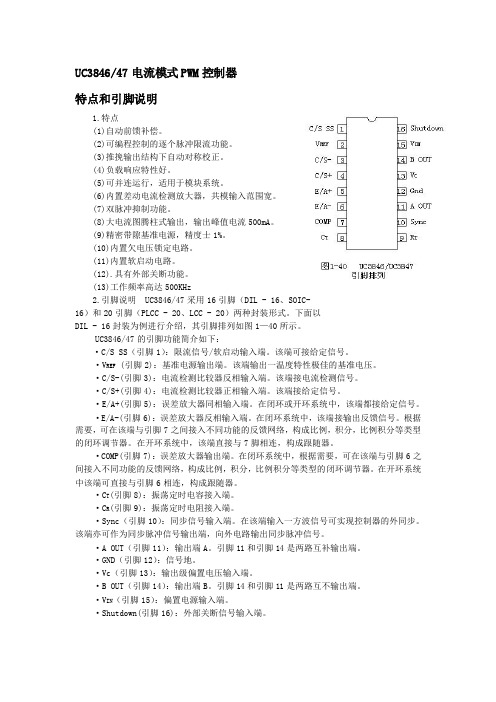
(13)工作频率高达500KHz2.引脚说明 UC3846/47采用16引脚(DIL - 16、SOIC-16)和20引脚(PLCC - 20、LCC - 20)两种封装形式。
下面以DIL - 16封装为例进行介绍,其引脚排列如图1—40所示。
UC3846/47的引脚功能简介如下:·C/S SS(引脚1):限流信号/软启动输入端。
该端可接给定信号。
·V REF (引脚2):基准电源输出端。
该端输出一温度特性极佳的基准电压。
·C/S-(引脚3):电流检测比较器反相输入端。
该端接电流检测信号。
·C/S+(引脚4):电流检测比较器正相输入端。
该端接给定信号。
·E/A+(引脚5):误差放大器同相输入端。
在闭环或开环系统中,该端都接给定信号。
·E/A-(引脚6):误差放大器反相输入端。
在闭环系统中,该端接输出反馈信号。
根据需要,可在该端与引脚7之间接入不同功能的反馈网络,构成比例,积分,比例积分等类型的闭环调节器。
在开环系统中,该端直接与7脚相连,构成跟随器。
·COMP(引脚7):误差放大器输出端。
在闭环系统中,根据需要,可在该端与引脚6之间接入不同功能的反馈网络,构成比例,积分,比例积分等类型的闭环调节器。
在开环系统中该端可直接与引脚6相连,构成跟随器。
·C T(引脚8):振荡定时电容接入端。
PIC16F1947-IPT详细介绍
PIC16F1947-IPT详细介绍PIC16F1947-I/PT详细介绍规格信息系列:PICXLP16F核心处理器:PIC核心尺寸:8-位速度:32MHz连接性:I2C,LIN,SPI,UART/USART外设:欠压检测/复位,LCD,POR,PWM,WDT I/O数:54程序存储容量:28KB(16K x 14)程序存储器类型:闪存EEPROM容量:256 x 8RAM容量:1K x 8电压-电源(Vcc/Vdd):1.8 V ~ 5.5 V数据转换器:A/D 17x10b振荡器类型:内部工作温度:-40°C ~ 85°C(TA)封装/外壳:64-TQFPPIC16F1947-I/PT特征高性能RISC CPU:·只有49条学习指南:- 除分支外的所有单周期指令·运行速度:-DC-32MHz振荡器/时钟输入-DC-125 ns指令周期·高达16K x14字的闪存程序存储器·高达1024字节的数据存储器(RAM)·具有自动上下文保存功能的中断功能·16级深度硬件堆栈·直接,间接和相对寻址模式·处理器对程序存储器的读访问特殊微控制器特点:·精密内部振荡器:- 工厂校准至±1%,典型值- 软件可选频率范围为32 MHz至31 kHz·省电睡眠模式·上电复位(POR)·上电延时定时器(PWRT)和振荡器起振定时器(OST)欠压复位(BOR):- 可在两个旅行点之间选择- 禁用睡眠选项·具有上拉/输入引脚的多路复用主机清零·可编程代码保护·高耐久性闪存/ EEPROM单元:-100,000写Flash耐力-1,000,000写入EEPROM耐久性- 闪存/数据EEPROM保留期:> 40年·宽工作电压范围:-1.8V-5.5V(PIC16F1946 / 47)-1.8V-3.6V(PIC16LF1946 / 47)。
- 1、下载文档前请自行甄别文档内容的完整性,平台不提供额外的编辑、内容补充、找答案等附加服务。
- 2、"仅部分预览"的文档,不可在线预览部分如存在完整性等问题,可反馈申请退款(可完整预览的文档不适用该条件!)。
- 3、如文档侵犯您的权益,请联系客服反馈,我们会尽快为您处理(人工客服工作时间:9:00-18:30)。
RCD16-47B®October 1998-Ed :2ANETWORK OF 16R-C-D LINETERMINATIONS RESISTANCE :R =47 Ω,TOLERANCE +/-10%CAPACITANCE:C =33pF,TOLERANCE+/-10%SCHOTTKY DIODE :(D)FEATURESIn any electronic equipment where a suitable bus terminationis requiredto avoidsignalreflectionsand distortions :PC and workstation computer Data-line analyzers MAIN APPLICATIONSFUNCTIONAL DIAGRAMDESCRIPTIONWith the increasing speed of data transmission,line reflections provide signal distorsions and the overshootsor undershootsproduced on the signal edges can cause the malfunction of the whole system.To avoid these negative effects from leading to problems,a suitable termination is required.Dedicated to bus termination,the RCD16-47B provides by far the best method to minimise stray emissions from PCB tracks.RCD NETWORKFOR BUS TERMINATIONApplication Specific DiscretesA.S.D.TMProvides impedance matching,thus increasing noise immunity and minimizing distortion.Lowers EMI /RFI radiation.No DC power dissipation.Eliminates negative voltages :no current will change the bias of the protected es the best of all termination schemes.BENEFITSMIL STD 883C -Method 3015-6-V PP =2kVC=100pF R =1500Ω-3positive strikes and 3negativestrikes (F=1Hz)COMPLIESWITH THE FOLLOWINGSTANDARDS:SO20SSOP202019181716151413121112345678109R =47 Ω,tolerance +/− 10 %C =33pF,tolerance +/-10%D =Schottky diode1/7RCD16-47BAPPLICATION NOTE:BUS TERMINATIONWith the increasing speed of data transmission(PC,TV,...),engineersare naturallyconfrontedwith effects that were of less significance with slower circuits.Among these are the effects described in transmission line theory:line reflections provide signal distortions and the overshoots or undershootsproduced on the signal edges can finally cause the malfunction of the whole system.1.Reflection at a non terminated lineThe figure below shows the circuit of a transmission system in which a memory device(input impedance of 100kΩ)is connectedat the end of a line with line impedance Zo.10Ω100kΩIf this line is not properly terminated,a certain amount of the energy is reflected back,inducing a reflection phenomenathat can distort the signal.This can result in improper operation of the system.The simulation shown on the above figure illustrates the signal distortion producedby line reflection at the end of the line which is not well terminated.Even if the signal at the start of the line has the correctform(upper curve),considerable distortion arises at the end of the line(lower curve).On the positive edge,the overshoot can exceed the maximum operating voltage of the used circuit technologywhich will then be destroyed.Also,the following negativeundershoot may reach a level low enough to change the value of the logic state.If it affectsof an addressline,a wrong memory cell will be addressed,and in the case of a data line,the data can be corrupted.This phenomenaalso occurs on the falling edge.To avoid these negative effects from leading to problems in a system,a suitable termination is required.2/7RCD16-47B2.The RCD terminationThe traditional solution to properly match each line of the bus consists of the use of several discrete resistances,capacitorsand small schottky diodes.For a16-bit bus,this requires48discrete components.SGS-THOMSON offers an innovating solution with a monolithic structure using ASD TM technology(*). The ASD TM technologyenables to integrate monolithically16of these RCD”basic cells”onto a single chip device.The RCD16-47B reduces component cost and assembly cost,saves board space and improves reliability.The simulation illustrates the signal distortion produced by line reflection at the end of the line when such a termination is used.The resistor provides the path termination for PCB track,thus resulting in low reflection phenomen a. The capacitor of33pF blocks DC currents while acting as a short circuit during signal transitions,and holds the bus at the last logic level.It reduces power consumption and avoids excessive current.The small Schottkydiode clamps the negative remaining undershoots which can result from impedance mismatch.This damps negative voltages and prevents the logic signal from rising above the logic level ’0’threshold after a falling edge.The RCD termination provides optimal solution compared to all other termination techniques.(*)ASD™=Apllicaion Specific Discretes.3/7Symbol Parameter and test conditionsTyp.Max.Unit R C Connection resistance (note1)T amb =25°C0.25ΩC t Total capacitance F =1MHz,V R =0V,V RMS =30mV45pF I R Leakage current V R =V RRM T j =25°C T j =70°C 110µA V FForward voltageI F =1mA I F =16mAT j =25°C T j =25°C0.51VNote 1:Rc is the resistance between pin 1and pin 11or between pin 10and pin 20ELECTRICAL CHARACTERISTICS Symbol ParameterValue Unit P Total power dissipation per package500mW I F Continuous forward current per Schottkydiode 50mA V RRM Repetitive peak reverse voltage 7.5V V PP Maximum electrostatic discharge MIL STD 883C -METHOD 3015-62kV T stg T jStorage temperature range Maximum junction temperature-55to +150150°C °CABSOLUTE MAXIMUM RATINGS (0°C ≤T amb ≤70°C)Symbol ParameterPackage Value Unit R th(j-a)Junction to ambientSO20SSOP20100140°C/WTHERMAL RESISTANCE RCD16-47B4/7PSPICE MODEL per RCD CELLLR13ΩR39ΩR247ΩC133pFCvarCvarDschot3nH SO201.75nH SSOP20tDschot parameters Cvar parametersZ magnitude versus frequencyPhase versus frequencyΩ°SO20PackageSSOP 20PackageΩZ magnitude versus frequency°Phase versus frequencyRCD16-47B5/7ORDER CODER C D16-47B RLProduct16cellsR =47ΩPackaging::tubeRL :tape &reelpackage :B =SO20B6=SSOP20Product PackageBase QtyTubeTape &reelRCD16-47B SO20401000RCD16-47B6SSOP20662000Type Package Marking RCD16-47B SO20RCD1647B RCD1647B6SSOP20RCD1647B6Packging :Preferred packaging is tape and reel.MARKINGRCD16-47B6/7SSOP20(Plastic)LEkbeA1110120DE1A 2A1cInformation furnished is believed to be accurate and reliable.However,STMicroelectronics assumes no responsibility for the consequences of use of such information nor for any infringementof patents or other rights of third parties which may result from its use.No license is granted by implication or otherwise under any patent or patent rights of STMicroelectronics.Specifications mentioned in this publication are subject to change without notice.This publication supersedes and replaces all information previously supplied.STMicroelectronics products are not authorized for use as critical components in life support devices or systems without express written ap-proval of STMicroelectronics.The ST logo is a registered trademark of STMicroelectronics ©1998STMicroelectronics -Printed in Italy -All rights reserved.STMicroelectronics GROUP OF COMPANIESAustralia -Brazil -Canada -China -France -Germany -Italy -Japan -Korea -Malaysia -Malta -Mexico -Morocco -The Netherlands -Singapore -Spain -Sweden -Switzerland -Taiwan -Thailand -United Kingdom -U.S.A.Khx45°CL AA1BeDE HREF.DIMENSIONSMillimeters InchesMin.Typ.Max.Min.Typ.Max.A 2.000.079A10.250.010A2 1.51 2.000.0590.079b 0.250.300.350.0100.0120.014c 0.100.350.0040.014D 7.058.050.2780.317E 7.608.700.2990.343E1 5.02 6.10 6.220.1980.2400.245e 0.650.026k 0°10°0°10°L0.250.500.800.0100.0200.031PACKAGE MECHANICAL DATA SO20(Plastic)REF.DIMENSIONSMillimeters InchesMin.Typ.Max.Min.Typ.Max.A 2.35 2.650.0920.104A10.100.200.0040.008B 0.330.510.0130.020C 0.230.320.0090.013D 12.613.00.4840.512E 7.407.600.2910.299e 1.270.050H 10.010.650.3940.419h 0.250.750.0100.029L 0.501.270.0200.050K8°(max)RCD16-47B7/7。
