CubeSuite_Code_Generator_for_ RL78
cubesuite编译器基本设置

7
RL78编译器设置
七、打开Build Tool—Variables/Functions Relocation Options —ROM/RAM Amount Information —Output ROM/RAM usage 选择“Yes” 译时可以显示ROM/RAM使用情况 这样编
4
RL78编译器设置
四、打开Build Tool—Compile Options—Data Control —【Pack structure members 】选择”Yes(-rc)” 表示结构体不对齐(默认对齐, 耗费字节空间)
1
RL78编译器设置
RL78编译器设置
二、双击Build Tool—Compile Options—Optimization —Perform optimization 选择 Yes(Code size)(-qx3)。设置优化方式。
Cubesuite+编译器设置
SUPERFLY
2014/03/3
© 2011 SUPERFLY TECHNOLOGY. All rights reserved.
Rev:1.1
RL78编译器设置
一、添加中文注释: Tool—Options—Text Editor,进行以下设置: • –勾除【Enable file encoding auto detection】 • –【Default file encoding】选择“Chinese Simplified(GB2312)”
RL78编译器设置
以上为基本设置,完成后则可以编写程序代码。至少应包含以下:Main()函数; hdwinit():硬件初始化函数;包含 “#pragma sfr #pragma DI #pragma EI #pragma NOP #pragma HALT #pragma STOP”(代码生成器可生成)的头文件。 编译器预处理指令 #pragma sfr:特殊功能寄存器声明 #pragma 指令:声明相关的汇编指令,以便在C语言中使用这些指令 DI:关中断指令 EI:开中断指令 NOP:空指令 HALT:HALT指令(进入等待模式) STOP:STOP指令(进入停止模式)
RL78G13快速入门教材介绍
使用要求以及注意事项 使用要求
在使用套件前,需要在PC机上安装CubeSuite+和USB驱动; CubeSuite+正常运行,必须保证PC机上安装有以下软件(详情见后): .NET Framework 4.0 SP1 Visual C++ runtime libraries (Visual C++ 2010 SP1 Redistributable Package)
不能放置于桌面及其他中 文名称的路径中!!
双击CubeSuitePlus_Package_V20000a.exe,程序自动解压 ② 程序解压完毕,弹出安装界面 ③ 确保已安装.NET Framework 4和Microsoft Visual C++ 2010 SP1 ④ 点击【Begin CubeSuite+ Setup】
10
Processor: At least 1 GHz (support for hyper threading/multicore CPU) Main memory: At least 1 GB (2 GB or higher fot Windows (64-bit OS)), 2 GB or higher recommended Display: Resolution at least 1,204 x 768; at least 65,536 colors Interface: USB 2.0 Windows XP (32bit) Windows Vista (32bit, 64bit) Windows 7 (32bit, 64bit) Windows 8 (32bit, 64bit) Microsoft .NET Framework 4 Runtime library of Microsoft Visual C++ 2010 SP1 Internet Explorer 6.0 or later
RL78族集成开发环境-RenesasElectronics

RL78族集成开发环境从CA78K0R转至CCRL的使用指南(编码篇)瑞萨电子(中国)有限公司2016/3/1 Rev.1.00前言▪本篇资料中,记述了使用C编译器CA78K0R创建的RL78族MCU的工程或者源码转至使用C编译器CC-RL的源码的差异。
▪本篇资料以用于RL78族的C编译器CA78K0R和CC-RL作为对象进行说明。
对象版本如下:▪CA78K0R V1.20或更高▪CC-RL V1.01.00目录▪编译器语言第04页▪汇编语言第20页▪函数调用接口第24页▪过渡支援功能第26页▪FAQ 第47页编译器语言编译器语言语言规格上的差异具体请参照编译器用户手册进行修改。
编译器语言语言规格上的差异具体请参照编译器用户手册进行修改。
编译器语言编译器语言▪枚举型说明符的差异内部表现形式因枚举范围的不同而变化。
▪CA78K0R的场合(优先顺序)范围:-128 ~ 127 → signed char范围: 0 ~ 255 → unsigned char范围: -32768 ~ 32767 → signed int▪CC-RL的场合(优先顺序)•指定-signed_char •不指定-signed_char范围: -128 ~ 127(包括0 ~ 127)→char 范围: -128 ~ 127 → signed char范围: 0 ~ 255 → unsigned char 范围: 0 ~ 255(包括0 ~ 127)→char范围:上述以外→ signed short 范围:上述以外→ signed short具体请参照编译器用户手册进行修改。
编译器语言包含头文件的差异具体请参照编译器用户手册进行修改。
编译器语言翻译限制的差异※ CA78K0R列,适用于V1.50及更新的版本。
具体请参照编译器用户手册进行修改。
编译器语言翻译限制的差异※ CA78K0R列,适用于V1.50及更新的版本。
具体请参照编译器用户手册进行修改。
CubeSuite+ 使用介绍
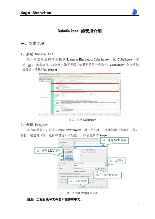
CubeSuite+ 的使用介绍一、创建工程1、启动 CubeSuite+在开始菜单的程序里找到 R enesas Electronics CubeSuite+ 的 CubeSuite+ 图标 , 单击执行,将会弹出如下界面。
如果不是第一次执行,CubeSuite+ 会自动加载最后一次执行的 Project。
图1.1 启动CubeSuite+2、创建 Project在启动界面中,点击 Create Now Project 框中的 GO ,选择创建一个新的工程,将打开创建对话框,选择和设定相关配置,开始创建新的○5、开始创建 图1.2 创建Project 对话框注意:工程目录和文件名不能带有中文。
3、CubeSuite+ 面板在这个面板中,你可以控制程序的执行和打开面板的调试过程。
查找下载编译图1.3 CubeSuite+ 面板Project Tree Panel :用于显示项目组件(微控制器、构建工具、调试工具等等)。
在这个树形结构的面板上,你可以选择或更改调试工具的使用。
Main Panel :主要编辑窗口。
OutPut Panel :各种操作的输出窗口。
二、编译工程1、代码自动生成CubeSuite+ 可以使用代码自动生成工具来进行MCU 内置的功能模块的功能设置,在CubeSuite+ 上选择MCU 内置的各个功能模块,设置以及输入需要的数值之后,代码生成工具就可以根据用户配置自动生成程序代码。
○3 图2.1 代码生成设置界面(1)在Project T ree Panel 中双击 Clock Generator 或点击 Main Panel 的Code Generator 开始代码生成设置,将打开如上界面;(2)在Code Generator(Design Tool)选择MCU内置的各个功能模块,设置以及输入需要的数值;(3)配置完成后,点击Main Panel 的Generate Code开始自动生成程序代码。
瑞萨单片机入门教程
瑞萨单片机入门教程本教程以R7F0C002L单片机为例一、开发环境下载安装与工程注意:该工程目录和工程名不能含有中文1.1、 CubeSuite+环境的下载:官网下载地址将安装环境下载到本地,该文件大小532M在安装过程中有提示需要填写注册码,请输入以下注册码,如果无效请联系供应商。
查看是否已经注册:在IDE环境中选择 Help->About后有下面窗口:注册码:67DCS-V3Q7L-XMGL9-FI6L9-EE1BJ该注册码有限制台数的,一旦注册了就会把MAC绑定,重装无需注册!当有以下报错时:请查看是否已经注册。
1.2、按照一般的软件安装方法安装好IDE环境,下面介绍IDE环境的配置:1、将DIF_RFP文件夹下的Device_Custom文件夹拷贝到安装目录下的C:\Program Files\Renesas Electronics\CubeSuite+下(这里是默认的安装目录,另外注意:DIF_RFP中Readme_Device_Custom.txt说将Device_Custom文件夹拷贝到C:\Program Files\Renesas Electronics\CubeSuite+\Device下,但是实际上不可以!)。
DIF_RFP文件夹安装根目录当配置成功以后会在芯片族里面多出R7F系列的单片机,如下图示:2、将DIF_RFP文件夹下的RFP_R7F0C002L_V10000子目录下面的两个文件(Device_Custom文件夹和Custom_Productlist.xml文件)拷贝到安装目录下的C:\Program Files\Renesas Electronics\Programming Tools\Renesas Flash Programmer V2.01\Device下(这里是默认安装路径)。
1.3、开发环境新建工程:1、启动CubeSuite+环境,会弹出如下启动界面:2、创建Project工程,在上述启动界面中,点击Creat New Project栏中GO按钮,将会弹出以下对话框:选择工程路径创建输入工程名选择芯片型号选择芯片族3、点击Create创建工程,会得到如下工程界面:4、通过生成工具生成一个简单的代码:5、将芯片型号换成R7F0C002单片机,并且将选项字节配置好!详细设置请参考第三章代码生成与编码。
CubeSuite+ 初步介绍与安装
CubeSuite+ 初步介绍与安装一、简介CubeSuite+ 能够与新款MCU RL78、RX 系列和采用传统CubeSuite 的MCU (如V850、78K0R 和78K0)一起使用。
瑞萨会不断扩大采用CubeSuite+的MCU 和开发工具的阵容,从而让您的开发环境变得越来越好、越来越快。
二、CubeSuite+ 的下载○1登录瑞萨官方网站(),查找并下载,在官网上还可找到众多CubeSuite+ 的资料。
也可以直接输入下面地址,联接下载页面下载官方版本。
/(/products/tools/ide/ide_cubesuite_plus/downloads.jsp ) ○2CubeSuite+ 安装包有两种格式,一种是单一综合包,包含软件的全部功能部件,但需要下载内容比较多;一种是分部件下载,可自己选择需要下载的功能部件,这样下载内容就会少很多。
(注意:初次下载需要在瑞萨电子官方网站注册一个帐号!)分部件下载三、CubeSuite+的安装○1安装前:安装的电脑中需要安装有下面两个软件,才能安装CubeSuite+:Microsoft .NET Framework 3.5 Service Pack 1Microsoft Visual C++ 2008 SP1 Redistributable Package Windows 7 系统只要安装有第二个就可以了。
注意:对于现在的64位系统,要注意电脑上安装的是不是(x86)版的Microsoft Visual C++ 2008 SP1 Redistributable,如果是(x64)版的,需要安装一个(x86)版本的。
○2安装:1、双击下载好的安装包,将弹出以下页面,请跟着红指针一步一步往下即可安装成功。
2、该窗口主要是软件说明和安装的注意事项,有兴趣的可细读。
往下查看页面,双击“ Begin CubeSuite+ Setup ” ,开始安装3、安装界面,点击下一步,4、同意,点击下一步5、可点击“Details”设定所需安装部件和安装目录,不需要的可直接点击下一步6、安装完成7、在开始中可查看已经安装好的软件,如果看到上面的画面,恭喜你!安装成功。
俄罗斯方块游戏编程
俄罗斯方块游戏编程俄罗斯方块是一款非常经典且富有挑战性的游戏,它起源于俄罗斯,现已风靡全球。
这款游戏的编程实现涉及到许多关键的算法和技术,下面将为大家介绍一下俄罗斯方块游戏的编程过程。
一、游戏的整体结构俄罗斯方块游戏的编程可以分为前端和后端两个部分。
前端是指游戏的界面和用户交互逻辑,后端则负责游戏的核心算法和各种游戏逻辑的实现。
在前端部分,需要实现游戏界面的绘制和刷新,包括游戏区域的绘制、方块的绘制和下落效果、得分的实时更新等。
同时,还需要监听玩家的键盘操作,控制方块的移动、旋转和下落。
前端的编程通常使用图形库或者游戏引擎进行实现,比如常用的Python图形库Pygame。
在后端部分,核心算法是方块的下落和碰撞检测。
方块的下落是整个游戏的核心,需要考虑到方块的速度、位置和边界等因素。
碰撞检测是指判断方块是否与其他方块或者游戏区域的边界发生碰撞,如果发生碰撞,则需要停止方块的下落,并进行相关的处理,比如消除已满的行、生成新方块等。
此外,游戏还需要实现游戏开始、暂停、结束等功能,以及相应的状态管理和逻辑判断。
二、方块的表示和操作在俄罗斯方块游戏的编程中,方块是整个游戏的基本组成单元。
方块通常使用二维数组来表示,数组中的每个元素代表方块的一个单元格。
通过对方块数组的操作,可以实现方块的移动、旋转等效果。
方块的移动可以通过改变方块数组中元素的位置来实现。
比如向左移动方块,只需要将方块数组中每个元素的列索引减一;向右移动方块,则将列索引加一。
类似地,对于方块的旋转,可以通过改变方块数组中元素的行列索引来实现。
需要注意的是,在改变方块的位置和形状时,要进行边界检测,以防止方块超出游戏区域或者与其他方块发生重叠。
三、碰撞检测和处理在俄罗斯方块游戏中,碰撞检测是一个非常关键的环节。
碰撞检测的主要目的是判断当前的方块是否与其他方块或者游戏区域的边界发生碰撞,从而决定方块是否需要停止下落,并进行相应的处理。
对于方块与其他方块的碰撞检测,可以通过比较方块数组和游戏区域数组中相应位置的元素来实现。
CC-RL C Compiler for RL78 Family Coding Techniques

© 2015 Renesas System Design Co., Ltd. All rights reserved.
Page 2
Introduction
• • • This document describes coding techniques to further reduce the code size or accelerate execution even after optimization through option settings when using the CC-RL C compiler. Each amount of code reduction shown in this document only applies to the corresponding example; the actual reduction will vary slightly between cases. The output assembly-language codes shown in this document are examples compiled with the medium model and the code size precedence option (-Osize) specified. Note that the output code will differ when a different type of optimization (default optimization or speed precedence optimization) is specified.
Page 9
mov1 mov1
CY,_data1.1 _data0.4,CY
瑞萨RL78单片机和开发工具(培训教程)[RL78 Tool introduce]
![瑞萨RL78单片机和开发工具(培训教程)[RL78 Tool introduce]](https://img.taocdn.com/s3/m/83c203c26137ee06eff918d4.png)
© 2011 Renesas Electronics Corporation. All rights reserved.
5
© 2011 Renesas Electronics Corporation. All rights reserved.
The basic operation of E1
User program execution Reset Tracing Break Performance measurement
E1
In-line programming by OCD OCD with programming function
E1
OS
Itron Compliance
Debugging by High Function Emulator In-circuit Emulator
IECUBE
REBJ-AN-MC-10001
RL78 Family Development Tool Lineup Useful tools at every development stage
Coding
Debugging
Debugging on PC
Programming
Programming by Renesas Ele.
RL7 8 / G 1 3
CubeSuite
Programmed
CPU Simulator Coding/ Building/ Device Driver IDE
In Renesas Electronics’s Factory
CubeSuite
Debugging by OCD On-Chip-Debugger with Programming function
瑞萨软件使用教程
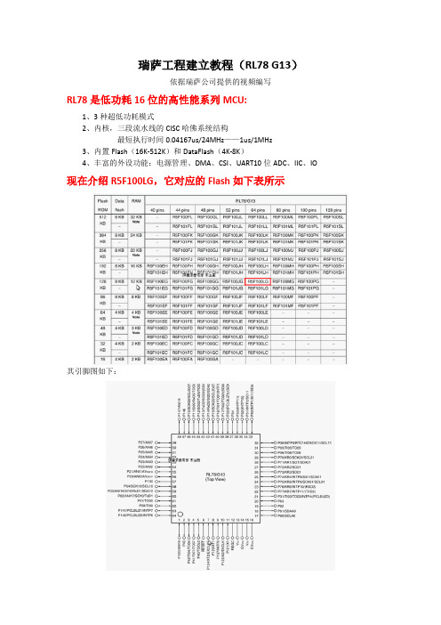
瑞萨工程建立教程(RL78 G13)依据瑞萨公司提供的视频编写RL78是低功耗16位的高性能系列MCU:1、3种超低功耗模式2、内核,三段流水线的CISC哈佛系统结构最短执行时间0.04167us/24MHz——1us/1MHz3、内置Flash(16K-512K)和DataFlash(4K-8K)4、丰富的外设功能:电源管理、DMA、CSI、UART10位ADC、IIC、IO 现在介绍R5F100LG,它对应的Flash如下表所示其引脚图如下:开发流程如图所示:瑞萨公司提供的开发板:工程建立工程:1、开发软件的安装:找到CubeSuitePlus_Package_V20000a软件,直接进行全信任的安装。
而另外两个软件:Microsoft Visual C++ 2010 SP1_x86和NET Framework 4_ x86_x64应该已经完全安装了,也可以再试着安装一下的(原来是旧版本的话)2、打开软件,在主界面中或者菜单栏里的projec中Create NEW project在出现的Create project对话框中,依次进行芯片选择,然后进行工程类型(项目、库、仿真)的选择、工程名、工程放置目录等设置。
3、在工程树种可以看到芯片的相关配置,然后在Code Generator中可以看到生成的代码,如果没有出现,则要在TOOL菜单中Plug-in Setting中的两个GODE选项都勾选中即可生成。
4、接着下面是配置和仿真工具的选择一定要注意Simulator是指软件仿真,如果选择此项会导致所连接的仿真器无现象了。
5、回到代码生成树目录里,第一项的Clock Generator有个感叹号,这里只是引脚映射没有设置好(一个引脚可以有多个功能选择),双击后在窗口里红色字的下面点击Fix setting完成默认设置。
接着一定要打开片上系统的选项:再根据速率要求,来设置时钟。
时钟后面部分默认设置了,6、到此,系统的必要条件基本满足了,接下来就进行代码生成:点击Generator Code生成代码然后在目录树中File下就可以看到生成的代码了。
CubeSuite+解决中文编码问题引起的编译错误
RENESAS CubeSuite+解决中文编码问题引起的编译错误标签:RENESAS; CubeSuite+; 中文注释; 编码; 编译错误; 中文乱码;
问题描述
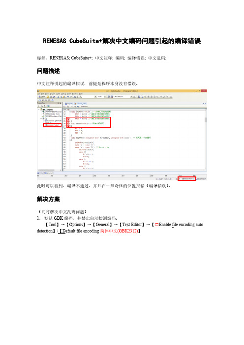
中文注释引起的编译错误,前提是程序本身没有错误。
此时可以看到,编译不通过,并且在一些奇怪的位置报错(编译错误)。
解决方案
(同时解决中文乱码问题)
1.默认GBK编码,并禁止自动检测编码。
【Tool】→【Options】→【General】→【Text Editor】→【□Enable file encoding auto detection】/【Default file encoding简体中文(GBK2312)】
2.设置【汉字代码源】为【EUC-JP(-ze)】
【Build Tool】→【Compile Options】→【Extension】→【Kanji character code of source】→【EUC-JP(-ze)】
结果呈现
问题顺利解决,没有出现任何编译错误,可以成功编译并下载调试。
光立方开发板程序下载方法及调试过程
光立方开发板程序下载方法及调试过程光立方开发板是一款基于FPGA的硬件开发平台,可执行数字信号处理、数字信号生成、图像和视频处理等任务。
本文将重点介绍在Windows系统下如何下载光立方开发板程序并进行调试。
一、准备工作在开始下载程序之前,我们需要先进行一些准备工作:1.安装Xilinx ISE软件,它是运行并下载FPGA程序的关键软件。
2.下载并安装光立方驱动,并将光立方开发板连接到电脑。
3.下载并安装JTAG烧录器,以便通过JTAG接口向开发板烧录程序。
4.准备好FPGA程序文件。
二、下载程序1.打开Xilinx ISE软件,创建新的工程。
选择FPGA型号并设置工程路径和名称。
2.添加UCF约束文件和FPGA程序文件。
在工程目录下,新建一个.ucf文件,并在ISE工具栏中选择Process-> Generate Programming File。
3.选择工程路径,将程序文件转换成比特流的数据文件。
这个文件后面将用于烧录到开发板上。
4.打开JTAG烧录器软件,然后设置好开发板的连接端口和IP地址。
5.将光立方开发板与电脑连接,并插上电源。
6.在ISE软件中,选择Tools-> iMPACT打开JTAG烧录器。
7.在打开的iMPACT窗口中,选择new project并命名。
8.选择Cable Setup-> Add Cable,将连接端口和IP地址配置给烧录器。
9.在iMPACT软件中选择File-> Open..打开比特流数据文件。
10.右键单击Xilinx硬件设备图标,选择Program,然后程序将开始下载。
下载完成后,iMPACT软件将提示“Successful”.三、调试程序下载完程序后,我们可以开始调试程序。
1.在ISE中打开ISE design suite command prompt,运行openJTAG,连接开发板。
2.连接到开发板后,运行xmd命令,进入调试模式。
cubeide常用函数
cubeide常用函数在Cubeide开发环境中,我们经常需要使用一些函数来完成特定的任务。
下面我将介绍一些常用的函数,它们在Cubeide中发挥着重要的作用。
一、文件操作函数1.文件打开函数:`fopen()``fopen()`函数用于打开文件,并返回一个文件指针。
它需要指定文件路径和打开模式(如读取、写入等)。
示例用法:`FILE*fp=fopen("example.txt","r");`2.文件关闭函数:`fclose()``fclose()`函数用于关闭已打开的文件。
它需要传入一个文件指针作为参数。
示例用法:`fclose(fp);`3.文件读写函数:`fread()`和`fwrite()``fread()`和`fwrite()`函数分别用于从文件中读取数据和向文件中写入数据。
它们都需要指定文件指针、缓冲区、读取/写入的大小和数量等参数。
示例用法:`fread(buffer,sizeof(char),1,fp);`或`fwrite(data,sizeof(int),1,fp);`二、字符串操作函数1.字符串拼接函数:`strcat()`和`strncat()``strcat()`和`strncat()`函数分别用于将一个字符串追加到另一个字符串的末尾。
它们都需要传入目标字符串和要追加的字符串。
示例用法:`charstr1[MAX_LENGTH]="Hello,";``strncat(str1,str2,MAX_LENGTH -strlen(str1),"\n");`2.字符串比较函数:`strcmp()`和`strncmp()``strcmp()`和`strncmp()`函数用于比较两个字符串。
它们都需要传入要比较的两个字符串。
示例用法:`if(strcmp(str1,str2)==0)`三、数组操作函数1.数组长度获取函数:`sizeof()`和`count()`(用于指针)`sizeof()`函数用于获取数组或结构体所占用的字节数。
rl78多线程run方法
rl78多线程run方法使用RL78进行多线程编程时,我们可以通过创建多个线程来实现并行处理。
一个RL78芯片中可以同时运行多个线程,每个线程拥有自己的程序计数器、寄存器和堆栈,可以同时执行不同的任务。
在RL78中,线程是通过定时中断来进行切换的,通过设置定时器中断的时间间隔来控制线程的切换频率。
在RL78中,每个线程都有一个独立的run方法,我们可以在该方法中编写线程要执行的任务。
这些任务可以是任何可实现的功能,例如读取传感器数据、执行算法、控制外设等等。
以一个简单的例子来说明如何在RL78中实现多线程编程。
假设我们有两个线程,一个用来读取温度传感器的数据,另一个用来控制LED灯的开关。
首先,我们需要定义两个线程的run方法。
在第一个线程的run方法中,我们可以使用AD转换模块来读取温度传感器的数据,并处理这些数据。
在第二个线程的run方法中,我们可以根据温度数据的不同来控制LED灯的开关。
接下来,我们需要在主函数中初始化两个线程。
首先,我们需要设置定时器中断的时间间隔,以控制线程的切换频率。
然后,我们需要创建和启动两个线程,使它们开始执行各自的任务。
在主函数中,我们还需要设置RL78的空闲模式,以确保当所有线程都处于空闲状态时,芯片能够进入省电模式,减少功耗。
最后,我们需要在定时器中断服务程序中切换线程。
当定时器中断发生时,我们可以使用线程调度算法选择下一个要执行的线程,并切换到该线程的上下文。
在切换线程时,我们需要保存当前线程的上下文,包括程序计数器、寄存器和堆栈指针等信息,并恢复下一个线程的上下文。
这样,下一个线程就可以从上次中断的地方继续执行。
总结一下,在RL78中实现多线程编程的步骤如下:1. 编写每个线程的run方法,定义线程要执行的任务。
2.在主函数中初始化和启动线程。
3.设置定时器中断的时间间隔,控制线程的切换频率。
4.在定时器中断服务程序中切换线程。
5.在切换线程时保存当前线程的上下文,并恢复下一个线程的上下文。
cubeide 格式化代码

cubeide 格式化代码
(原创版)
目录
1.CubeIDE 简介
2.CubeIDE 格式化代码的功能
3.如何使用 CubeIDE 格式化代码
4.CubeIDE 格式化代码的优点
5.总结
正文
CubeIDE 是一款功能强大的代码编辑器,广泛应用于各种编程语言的编写和调试。
它不仅支持多种编程语言,还具有强大的代码自动补全、调试、测试等功能,大大提高了程序员的编写效率。
在 CubeIDE 中,格式化代码是一个非常实用的功能。
它可以帮助程序员快速地格式化代码,使代码看起来更加清晰、易于阅读和维护。
CubeIDE 支持多种编程语言的代码格式化,包括 Java、C++、Python 等。
要使用 CubeIDE 格式化代码,首先需要打开 CubeIDE,并打开需要格式化的代码文件。
然后,在代码编辑器中选择需要格式化的代码,或者使用快捷键“Ctrl+Shift+F”进行格式化。
CubeIDE 会自动对选中的代码进行格式化,使代码排版更加整齐、缩进更加统一。
CubeIDE 格式化代码的优点在于,它可以帮助程序员快速地格式化代码,节省了大量的时间和精力。
同时,CubeIDE 的代码格式化功能符合编程规范,使代码更加规范、易于阅读和维护。
此外,CubeIDE 支持多种编程语言的代码格式化,可以满足不同程序员的需求。
总之,CubeIDE 是一款功能强大的代码编辑器,格式化代码功能是其中的一项实用功能。
源码编辑器随机数模块测试题
源码编辑器随机数模块测试题在开发软件或网站时,很多情况下都需要用到随机数模块。
一个好的源码编辑器随机数模块可以帮助开发人员快速生成高质量的随机数,降低开发难度。
下面介绍一些参考内容,有助于开发人员快速实现源码编辑器随机数模块。
1. 随机数的种类在实现源码编辑器随机数模块时,需要考虑使用的随机数类型。
常见的随机数类型有伪随机数和真随机数。
伪随机数生成器是基于某种算法,根据已知的随机数种子生成随机数序列。
真随机数则来源于真正的随机事件,如热噪声、光子计数等。
在大多数情况下,伪随机数已足够满足需求。
2. 随机数的生成方法实现源码编辑器随机数模块时,需要考虑使用的随机数生成方法。
常见的生成方法有线性同余发生器、Mersenne Twister等。
线性同余发生器是一种简单的伪随机数生成方法,基于一个随机数种子,通过迭代计算生成一系列随机数。
Mersenne Twister则是一种高质量的伪随机数生成方法,生成的随机数均匀分布在一个大范围内,并且不容易产生重复序列。
3. 随机数的应用场景源码编辑器随机数模块可以应用于很多场景中,如生成随机密码、生成随机验证码、模拟随机事件等。
在实现模块时,需要根据应用场景来选择合适的方法和参数设置。
例如,在生成随机密码时,需要考虑密码强度和长度等因素。
4. 随机数的安全性源码编辑器随机数模块生成的随机数是伪随机数,如果种子值被预测,随机数就会失去安全性。
因此,在实现源码编辑器随机数模块时,需要考虑安全性问题。
例如,在生成随机数时,要使用加密的随机种子值和密钥来保证随机数的安全性。
5. 随机数的测试方法实现源码编辑器随机数模块后,需要进行测试来验证随机数的生成质量。
常用的测试方法有统计测试和挑战测试。
统计测试是通过对生成的随机数序列进行统计分析,检查是否符合统计随机性的特征。
挑战测试则是将生成的随机数序列用于一些加密算法等,检查是否能够承受攻击的能力。
通过上述参考内容,开发人员可以更好地了解源码编辑器随机数模块的实现和应用。
关于cubesuite+的安装与配置
关于cubesuite+的安装与配置开发⼯具软件CubeSuite+的安装与配置注意1:CubeSuite+软件不能安装在中⽂路径中,单⽚机程序也不⽤使⽤中⽂⽂件名或在中⽂路径下进⾏编译和调试。
注意2:CubeSuite+软件可以在32/64位操作系统XP、Win7下安装,但是同时也要求计算机中装有.net库。
⼀般Win7系统都⾃带.net库,⽽XP系统则可能需要另⾏安装.net 库。
如系统没有安装.net库,可在微软官⽹下载.net Framework安装包进⾏安装。
下载地址:/doc/b6d13a7b50e2524de4187e74.html /zh-cn/download/details.aspx?id=17718⼀、CubeSuite+软件安装安装路径可以按照个⼈选择进⾏设置(注意选择英⽂路径),其余设置依照默认选项,点击“下⼀步“即可。
⼆、在开发环境中建⽴⼯程及参数设置以下针对uPD78F0485单⽚机的开发为例进⾏说明。
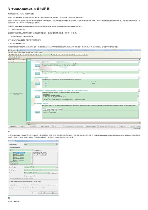
1、运⾏CubeSuiteW+软件从开始菜单的程序中找到CubeSuiteW+运⾏,或者根据CubeSuiteW+软件安装路径找到CubeSuiteW+软件运⾏,是CubeSuiteW+软件的图标。
运⾏程序后进⼊图1界⾯。
图12. 进⼊Project New Project功能(图1中第2项),弹出图2界⾯,按图 2所⽰先选择单⽚机系列78K0,然后根据实验盒上单⽚机型号(uPD78F0485(80pin)或uPD78F0495(80pin))在78K0/LF3下选择对应的芯⽚,再输⼊⼯程名、选择⼯程路径(不能是中⽂路径),最后点击“Create”按钮完成新建⼯程操作。
图23.选择仿真器型号在开发环境的左侧⼀栏中,选择78K0 Simulator (Dubug),右击,选择Using Debug Tool 下的78K0 EZ Emulator。
如图3所⽰。
图34. 选择时钟源仿真器型号选定后会出现如图4所⽰界⾯,在Clock选项中将Main clock source选为Genarate by emulator,接着设置主时钟频率为8。
stm32cubeide编码
stm32cubeide编码STM32CubeIDE是STMicroelectronics提供的一款功能强大的集成开发环境(IDE),用于开发STM32系列微控制器的软件。
在STM32CubeIDE中,可以使用多种编程语言来进行编码,主要包括C语言和C++语言。
编码主要涉及以下几个方面:1. 编写主程序:使用C或C++语言编写主程序代码,包括初始化引脚、配置外设、实现功能等。
2. 编写驱动程序:针对特定外设编写驱动程序,使用C或C++语言编写代码来控制外设的初始化和功能实现。
3. 编写中断服务程序:使用C或C++语言编写中断服务程序代码,处理外部中断或定时器中断事件。
4. 调试程序:使用调试器进行程序调试,可以单步执行程序、查看变量的值,以及检测代码中的错误。
编码时需要注意以下几个方面:1. 硬件抽象层(HAL)库:STM32CubeIDE提供了一套硬件抽象层(HAL)库,可以简化底层外设的操作。
通过使用HAL库,可以方便地配置和控制STM32芯片的各个外设。
2. 引脚定义:在编码过程中,需要根据芯片引脚的功能和连接电路进行配置。
通常需要使用引脚定义文件(如stm32f4xx_hal_gpio.h)对引脚进行初始化和配置。
3. 寄存器级编程:在一些特定情况下,可能需要直接操作寄存器进行底层编程。
这需要了解芯片的寄存器映射和寄存器的具体功能。
4. 中断处理:中断是STM32系统的重要功能之一,需要熟悉中断优先级和中断向量表等概念,以及相应的中断处理函数编写方法。
总之,STM32CubeIDE提供了强大的开发环境和丰富的开发工具,可以帮助开发者更快速、高效地进行STM32微控制器的编码工作。
- 1、下载文档前请自行甄别文档内容的完整性,平台不提供额外的编辑、内容补充、找答案等附加服务。
- 2、"仅部分预览"的文档,不可在线预览部分如存在完整性等问题,可反馈申请退款(可完整预览的文档不适用该条件!)。
- 3、如文档侵犯您的权益,请联系客服反馈,我们会尽快为您处理(人工客服工作时间:9:00-18:30)。
CubeSuite+ Code Generator for RL78,78K0R,78K0 V2.00.00Release NoteContents Chapter 1. Target Devices (3)Chapter 2. User's Manuals (11)Chapter 3. Key Points for Selecting Uninstallation Method (12)Chapter 4. Changes (13)4.1 Details of Changes (14)4.1.1 Output code changes of real-time clock (14)4.1.2 Output code changes of serial array unit (15)4.1.3 Addition of PMC register setup (17)4.1.4 Change of output source file name (18)4.1.5 Output code changes of the receiving function of UARTn (19)4.1.6 Control correction of a competition pin (19)4.1.7 GUI correction of an A/D converter (19)4.1.8 Conversion time setup of A/D correction (20)4.1.9 Changes of square wave output of a timer (20)4.1.10 Changes of the TTL check box of a port (20)4.1.11 Changes of PIOR setup (20)4.1.12 Changes of TAU1 setup (20)4.1.13 Changes of UART2 setup (21)4.1.14 Changes of key interrupt function (21)4.1.15 Changes of Simplified I2C (21)4.1.16 Additional function generation file mode (22)4.1.17 Changes of hdwinit() function (23)4.1.18 Changes of API about Simplified I2C by SAU (24)4.1.19 Changes of the timer RD and the timer RJ0, and new restriction (25)4.1.20 Changes of input pulse interval measurement of TAU (27)4.1.21 Changes the time of the channel 2 output of TAU1 (27)4.1.22 Changes the notation of a power supply........................................................................ 28 R20UT2530EJ0100 Rev.1.00 March 12, 2013Chapter 5. Cautions (29)5.1Cautions List (29)5.2Cautions Details (30)5.2.1 Cautions of the LIN-bus function of UART2 or UART3 or UART6 (30)5.2.2 Cautions of the operation for slave transmission of serial interface IICA or IIC0 (30)5.2.3 Cautions of extension code, multimaster,wakeup function of serial interface IICA or IIC0 .. 305.2.4 Cautions of cooperation with the linker option (31)5.2.5 Cautions of CAN controllers (31)5.2.6 Cautions of PORT (31)5.2.7 Cautions of the SNOOZE mode of Serial array unit 1 (31)5.2.8 Cautions of a setup of a real-time clock (31)5.2.9 Cautions when using a DTC function (32)5.2.10 Cautions of initial function of an A/D converter (33)5.2.11 Cautions of initial function at the time of setting up UART transmission (33)5.2.12 Conversion time setup of A/D correction (33)5.2.13 Cautions of Complementary assistant PWM mode of TimerRD (33)5.2.14 Cautions of Pin Configurator (33)5.2.15 Cautions of Safety Functions (33)5.2.16 Cautions of critical errors (34)Chapter 6. Restrictions (35)6.1Restrictions List (35)6.2Restrictions Details (35)6.2.1 Restrictions of the coding rule of MISRA-C (35)6.2.2 Restrictions of High-speed on-chip oscillator frequency select register (35)6.2.3 Restrictions of internal low-speed or internal high-speed oscillator trimming (35)6.2.4 Restriction of a serial array unit (35)Chapter 7. Changes in User’s Manual (36)7.1API added and changed by V1.00.02. (36)7.1.1 The API table changed or added by RL78 Code Generator function (36)7.1.2 Details of API added by RL78 Code Generator function (40)Chapter 1. Target DevicesBelow is a list of devices supported by the Code Generator for RL78/I1A V2.00.00.04 PIN Device name20pin R5F1076C30pin R5F107AC, R5F107AE32pin R5F107BC38pin R5F107DEThe Code Generator is based on the following documents.Manual Name Document Number RL78/I1A User's Manual: HardwareR01UH0169JJ0002 Rev.0.02R01UH0169EJ0002 Rev.0.02Below is a list of devices supported by the Code Generator for RL78/G12 V2.00.00.07 PIN Device name20pin R5F10266, R5F10267, R5F10268, R5F10269, R5F1026A R5F10366, R5F10367, R5F10368, R5F10369, R5F1036A24pin R5F10277, R5F10278, R5F10279, R5F1027A R5F10377, R5F10378, R5F10379, R5F1037A30pin R5F102A7, R5F102A8, R5F102A9, R5F102AA R5F103A7, R5F103A8, R5F103A9, R5F103AAThe Code Generator is based on the following documents.Manual Name Document Number RL78/G12 User's Manual: HardwareR01UH0200JJ0100 Rev.1.00R01UH0200EJ0100 Rev.1.00Below is a list of devices supported by the Code Generator for RL78/G13 V2.00.00.07 PIN Device name20pin R5F1006A, R5F1006C, R5F1006D, R5F1006E R5F1016A, R5F1016C, R5F1016D, R5F1016E24pin R5F1007A, R5F1007C, R5F1007D, R5F1007E R5F1017A, R5F1017C, R5F1017D, R5F1017E25pin R5F1008A, R5F1008C, R5F1008D, R5F1008E R5F1018A, R5F1018C, R5F1018D, R5F1018E30pin R5F100AA, R5F100AC, R5F100AD, R5F100AE, R5F100AF, R5F100AG R5F101AA, R5F101AC, R5F101AD, R5F101AE, R5F101AF, R5F101AG32pin R5F100BA, R5F100BC, R5F100BD, R5F100BE, R5F100BF, R5F100BG R5F101BA, R5F101BC, R5F101BD, R5F101BE, R5F101BF, R5F101BG36pin R5F100CA, R5F100CC, R5F100CD, R5F100CE, R5F100CF, R5F100CG R5F101CA, R5F101CC, R5F101CD, R5F101CE, R5F101CF, R5F101CG40pin R5F100EA, R5F100EC, R5F100ED, R5F100EE, R5F100EF, R5F100EG, R5F100EH R5F101EA, R5F101EC, R5F101ED, R5F101EE, R5F101EF, R5F101EG, R5F101EH44pin R5F100FA, R5F100FC, R5F100FD, R5F100FE, R5F100FF, R5F100FG, R5F100FH R5F100FJ, R5F100FK, R5F100FLR5F101FA, R5F101FC, R5F101FD, R5F101FE, R5F101FF, R5F101FG, R5F101FH R5F101FJ, R5F101FK, R5F101FL48pin R5F100GA, R5F100GC, R5F100GD, R5F100GE, R5F100GF, R5F100GG, R5F100GH R5F100GJ, R5F100GK, R5F100GLR5F101GA, R5F101GC, R5F101GD, R5F101GE, R5F101GF, R5F101GG, R5F101GH R5F101GJ, R5F101GK, R5F101GL52pin R5F100JC, R5F100JD, R5F100JE, R5F100JF, R5F100JG, R5F100JH R5F100JJ, R5F100JK, R5F100JLR5F101JC, R5F101JD, R5F101JE, R5F101JF, R5F101JG, R5F101JH R5F101JJ, R5F101JK, R5F101JL64pin R5F100LC, R5F100LD, R5F100LE, R5F100LF, R5F100LG, R5F100LH R5F100LJ, R5F100LK, R5F100LLR5F101LC, R5F101LD, R5F101LE, R5F101LF, R5F101LG, R5F101LH R5F101LJ, R5F101LK, R5F101LL80pin R5F100MF, R5F100MG, R5F100MH, R5F100MJ, R5F100MK, R5F100ML R5F101MF, R5F101MG, R5F101MH, R5F101MJ, R5F101MK, R5F101ML100pin R5F100PF, R5F100PG, R5F100PH, R5F100PJ, R5F100PK, R5F100PL R5F101PF, R5F101PG, R5F101PH, R5F101PJ, R5F101PK, R5F101PL128pin R5F100SH, R5F100SJ, R5F100SK, R5F100SL R5F101SH, R5F101SJ, R5F101SK, R5F101SLThe Code Generator is based on the following documents.Manual Name Document Number RL78/G13 User's Manual: HardwareR01UH0146JJ0210 Rev.1.00R01UH0146EJ0210 Rev.1.00Below is a list of devices supported by the Code Generator for RL78/G14 V2.00.00.07PIN Device name30pin R5F104AA, R5F104AC, R5F104AD, R5F104AE, R5F104AF, R5F104AG32pin R5F104BA, R5F104BC, R5F104BD, R5F104BE, R5F104BF, R5F104BG36pin R5F104CA, R5F104CC, R5F104CD, R5F104CE, R5F104CF, R5F104CG40pin R5F104EA, R5F104EC, R5F104ED, R5F104EE, R5F104EF, R5F104EG, R5F104EH44pin R5F104FA, R5F104FC, R5F104FD, R5F104FE, R5F104FF, R5F104FG, R5F104FH R5F104FJ48pin R5F104GA, R5F104GC, R5F104GD, R5F104GE, R5F104GF, R5F104GG, R5F104GH R5F104GJ52pin R5F104JC, R5F104JD, R5F104JE, R5F104JF, R5F104JG, R5F104JH, R5F104JJ 64pin R5F104LC, R5F104LD, R5F104LE, R5F104LF, R5F104LG, R5F104LH, R5F104LJ 80pin R5F104MF, R5F104MG, R5F104MH, R5F104MJ100pin R5F104PF, R5F104PG, R5F104PH, R5F104PJThe Code Generator is based on the following documents.Manual Name Document Number RL78/G14 User's Manual: HardwareR01UH0186JJ0100 Rev.1.00R01UH0186EJ0100 Rev.1.00Below is a list of devices supported by the Code Generator for RL78/G1A V2.00.00.04PIN Device name25pin R5F10E8A, R5F10E8C, R5F10E8D, R5F10E8E32pin R5F10EBA, R5F10EBC, R5F10EBD, R5F10EBE48pin R5F10EGA, R5F10EGC, R5F10EGD, R5F10EGE64pin R5F10ELC, R5F10ELD, R5F10ELEThe Code Generator is based on the following documents.Manual Name Document Number RL78/G1A User's Manual: HardwareR01UH0305JJ0002 Rev.0.02R01UH0305EJ0002 Rev.0.02Below is a list of devices supported by the Code Generator for RL78/F12 V2.00.00.07 PIN Device name20pin R5F109AE, R5F109AD, R5F109AC, R5F109AB, R5F109AA30pin R5F109BE, R5F109BD, R5F109BC, R5F109BB, R5F109BA32pin R5F109BE, R5F109BD, R5F109BC, R5F109BB, R5F109BA48pin R5F109GE, R5F109GD, R5F109GC, R5F109GB, R5F109GA64pin R5F109LE, R5F109LD, R5F109LC, R5F109LB, R5F109LAThe Code Generator is based on the following documents.Manual Name Document NumberR01UH0231JJ0003 Rev.0.03 RL78/F12 User's Manual: HardwareR01UH0231EJ0003 Rev.0.03Below is a list of devices supported by the Code Generator for RL78/L12 V2.00.00.07 PIN Device name32pin R5F10RBC, R5F10RBA, R5F10RB844pin R5F10RFC, R5F10RFA, R5F10RF848pin R5F10RGC, R5F10RGA, R5F10RG852pin R5F10RJC, R5F10RJA, R5F10RJ864pin R5F10RLC, R5F10RLAThe Code Generator is based on the following documentsManual Name Document NumberR01UH0330JJ0003 Rev.0.03 RL78/L12 User's Manual: HardwareR01UH0330EJ0003 Rev.0.03Below is a list of devices supported by the Code Generator for 78K0R/Fx3 V2.00.00.06 Nickname Device name78K0R/FB3 μPD78F1804, μPD78F1805, μPD78F1806, μPD78F180778K0R/FC3 μPD78F1808, μPD78F1809, μPD78F1810, μPD78F1811μP D78F1812, μPD78F1813, μPD78F1814, μPD78F1815, μPD78F1816, μPD78F1817 μPD78F1826, μPD78F1827, μPD78F1828, μPD78F1829, μPD78F183078K0R/FE3 μPD78F1818, μPD78F1819, μPD78F1820, μPD78F1821, μPD78F1822 μPD78F1831, μPD78F1832, μPD78F1833, μPD78F1834, μPD78F183578K0R/FF3 μPD78F1823, μPD78F1824, μPD78F1825μPD78F1836, μPD78F1837, μPD78F1838, μPD78F1839, μPD78F184078K0R/FG3 μPD78F1841, μPD78F1842, μPD78F1843, μPD78F1844, μPD78F1845 The Code Generator is based on the following documents.Manual Name Document Number78K0R/Fx3 User’s Manual U19145JJ1V0UD00 U19145EJ1V0UD00Below is a list of devices supported by the Code Generator for 78K0R/Ix3 V2.00.00.07 Nickname Device name78K0R/IB3 μPD78F1201, μPD78F120378K0R/IC3 μPD78F1211(38pin), μPD78F1213(38pin), μPD78F1211(44pin), μPD78F1213(44pin)78K0R/ID3 μPD78F1213(48pin), μPD78F1214(48pin), μPD78F1215(48pin) μPD78F1223, μPD78F1224,μPD78F122578K0R/IE3 μPD78F1233, μPD78F1234,μPD78F1235The Code Generator is based on the following documents.Manual Name Document Number78K0R/Ix3 User’s Manual U19678JJ1V1UD00 U19678EJ1V1UD00Below is a list of devices supported by the Code Generator for 78K0R/Kx3 V2.00.00.07 Nickname Device name78K0R/KE3 μPD78F1142/A, μPD78F1143/A, μPD78F1144/A, μPD78F1145/A, μPD78F1146/A 78K0R/KF3 μPD78F1152/A, μPD78F1153/A, μPD78F1154/A, μPD78F1155/A, μPD78F1156/A78K0R/KG3 μPD78F1162/A, μPD78F1163/A, μPD78F1164/A, μPD78F1165/A, μPD78F1166/A, μPD78F1167/A, μPD78F1168/A78K0R/KH3 μPD78F1174/A, μPD78F1175/A, μPD78F1176/A, μPD78F1177/A, μPD78F1178/A 78K0R/KJ3 μPD78F1184A, μPD78F1185A, μPD78F1186A, μPD78F1187A, μPD78F1188A The Code Generator is based on the following documentsManual Name Document Number78K0R/KE3 User’s Manual U17854JJ8V0UD00 U17854EJ8V0UD0078K0R/KF3 User’s Manual U17893JJ7V0UD00 U17893EJ7V0UD0078K0R/KG3 User’s Manual U17894JJ8V0UD00 U17894EJ8V0UD0078K0R/KH3 User’s Manual U18432JJ4V0UD00 U18432EJ4V0UD0078K0R/KJ3 User’s Manual U18417JJ3V0UD00 U18417EJ3V0UD00Below is a list of devices supported by the Code Generator for 78K0R/Kx3-A V2.00.00.07 Nickname Device name78K0R/KE3-A μPD78F1016, μPD78F1017, μPD78F1018The Code Generator is based on the following documentsManual Name Document Number78K0R/Kx3-A User’s Manual U19653JJ1V0UD U19653EJ1V0UDBelow is a list of devices supported by the Code Generator for 78K0R/Kx3-L V2.00.00.07 Nickname Device name78K0R/KC3-L μPD78F1000(44pin), μPD78F1001(44pin), μPD78F1002(44pin),μPD78F1003(44pin),μPD78F1001(48pin), μPD78F1002(48pin), μPD78F1003(48pin)78K0R/KD3-L μPD78F1004, μPD78F1005, μPD78F100678K0R/KE3-L μPD78F1007, μPD78F1008, μPD78F100978K0R/KF3-L μPD78F1010, μPD78F1011, μPD78F101278K0R/KG3-L μPD78F1013, μPD78F1014The Code Generator is based on the following documentsManual Name Document Number78K0R/Kx3-L User’s Manual U19291JJ3V0UD00 U19291EJ2V0UD0078K0R/KF3–L User’s Manual U19459JJ1V0UD00 U19459EJ1V0UD0078K0R/KG3-L User’s Manual U19460JJ1V0UD00 U19460EJ1V0UD00Below is a list of devices supported by the Code Generator for 78K0R/Lx3 V2.00.00.07 Nickname Device name78K0R/LF3 μPD78F1500, μPD78F1501, μPD78F150278K0R/LG3 μPD78F1503, μPD78F1504, μPD78F150578K0R/LH3 μPD78F1506, μPD78F1507, μPD78F1508The Code Generator is based on the following documentsManual Name Document Number78K0R/Lx3 User’s Manual U19155JJ3V0UD U19155EJ3V0UDBelow is a list of devices supported by the Code Generator for 78K0/Ix2 V2.00.00.04 Nickname Device name78K0/IY2 μPD78F0740, μPD78F0741, μPD78F0742, μPD78F0750, μPD78F0751, μPD78F075278K0/IA2 μPD78F0743, μPD78F0744, μPD78F0753, μPD78F075478K0/IB2 μPD78F0745, μPD78F0746, μPD78F0755, μPD78F0756 32pin are not supporting.The Code Generator is based on the following documents.Manual Name Document Number78K0/Ix2 User’s Manual U19353JJ3V0UD00 U19353EJ3V0UD00Below is a list of devices supported by the Code Generator for 78K0/Kx2-L V2.00.00.04 Nickname Device name78K0/KY2-L μPD78F0550, μPD78F0551, μPD78F0552, μPD78F0555, μPD78F0556, μPD78F055778K0/KA2-L μPD78F0560, μPD78F0561, μPD78F0562, μPD78F0565, μPD78F0566, μPD78F056778K0/KB2-L μPD78F0571, μPD78F0572, μPD78F0573, μPD78F0576, μPD78F0577, μPD78F057878K0/KC2-L μPD78F0581(44pin), μPD78F0582(44pin), μPD78F0583(44pin), μPD78F0581(48pin), μPD78F0582(48pin), μPD78F0583(48pin), μPD78F0586(44pin), μPD78F0587(44pin), μPD78F0588(44pin), μPD78F0586(48pin), μPD78F0587(48pin), μPD78F0588(48pin)The Code Generator is based on the following documents.Manual Name Document Number78K0/Kx2-L User’s Manual U19111JJ2V1UD U19111EJ2V1UDChapter 2. User's ManualsPlease read the following user's manuals together with this document.Manual Name Document Number CubeSuite+ V1.03.00 RL78 Design R20UT2136EJ0100CubeSuite+ V1.03.00 78K0R Design R20UT2137EJ0100CubeSuite+ V1.03.00 78K0 Design R20UT2138EJ0100CubeSuite+ V2.00.00 Message R20UT2448EJ0100Chapter 3. Key Points for Selecting Uninstallation MethodThere are two ways to uninstall this product.•Use the integrated uninstaller (uninstalls CubeSuite+)•Use separate uninstaller (uninstalls this product only)To use the separate uninstaller, select the following from the Control Panel:•Add/Remove Programs (Windows XP)•Programs and Features (Windows Vista, Windows 7, Windows 8)Then select "CubeSuite+ Code Generator for RL78_78K".Chapter 4. Changes This chapter describes change from V1.00.06 to V2.00.00No 内容Corresponds of code generation RL78/L12 RL78/F12 RL78/G1A RL78/G12 RL78/G13 RL78/G14 RL78/I1A 78K0R/Fx3 78K0R/Ix3 78K0R/Kx3 78K0R/Kx3-A 78K0R/Kx3-L 78K0R/Lx3 78K0/Ix2 78K0/Kx2-L V2.00.00.07 V2.00.00.07 V2.00.00.04 V2.00.00.07 V2.00.00.07 V2.00.00.07 V2.00.00.04 V2.00.00.06 V2.00.00.07 V2.00.00.07 V2.00.00.07 V2.00.00.07 V2.00.00.07 V2.00.00.04 V2.00.00.041 Output code changes of real-time clock / / / - - - - / / / / / / / /2 Output code changes of serial array unit / / / - - - - / / / / / / / /3 Addition of PMC register setup / / / - - - / / / / / / / / /4 Change of output source file name / / / - - - - / / / / / / / /5 Output code changes of the receiving functionof UARTn/ / / - - - - / / / / / / / /6 Control correction of a competition pin / / / / - / / / / / / / / / /7 GUI correction of an A/D converter / / / - - - / / / / / / / / /8 Conversion time setup of A/D correction / / - / / / / / / / / / / / /9 Changes of square wave output of a timer / / / / / / / / / / / / / / /10 Changes of the TTL check box of a port / / / / / / / / / / / / / / /11 Changes of PIOR setup / / / / / / / / / / / / / / /12 Changes of TAU1 setup / / / / / / / / / / / / / / /13 Changes of UART2 setup / / / / / / / / / / / / / / /14 Changes of key interrupt function / / / / / / / / / / / / / / /15 Changes of Simplified I2C / / / / / / / / / / / / / / /16 Additional function generation file mode ○○○○○○○○○○○○○○○17 Changes of hdwinit() function ○○○○○○○○○○○○○○○18 Changes of API about Simplified I2C by SAU / / / / / / / - - - - - - / /19 Changes of the timer RD and the timer RJ0 / / / / / - / / / / / / / / /20 Changes of input pulse interval measurementof TAU- - - - - - - - - - - - - / /21 Changes the time of the channel 2 output ofTAU1/ / / / / / / - / / / / / / / 22 Changes the notation of a power supply / / / - / / / / / / / / / / / : Correspondence, -: Not correspondence(finish of correction), : Outside of function4.1 Details of Changes4.1.1 Output code changes of real-time clocka) The output code of R_RTC_Set_ConstPeriodInterruptOff() was changes.Before:void R_RTC_Set_ConstPeriodInterruptOff(void){RTCC0 &= _88_RTC_INTRTC_CLEAR;RTCIF = 0U; /* clear INTRTC interrupt flag */}After:void R_RTC_Set_ConstPeriodInterruptOff(void){RTCC0 &= _F8_RTC_INTRTC_CLEAR;RTCC1 &= (uint8_t)~_08_RTC_INTC_GENERATE_FLAG;RTCIF = 0U; /* clear INTRTC interrupt flag */}b) The output code of R_RTC_Interrupt( ) was changes.- When an alarm interrupt function is checked.Before:__interrupt void R_RTC_Interrupt(void){R_RTC_Callback_Alarm();}After:__interrupt static void r_rtc_interrupt(void){if (1U == WAFG){RTCC1 &= (uint8_t)~_10_RTC_ALARM_MATCH; /* clear WAFG */r_rtc_callback_alarm();}}- When a constant-period interruption function is checkedBefore:__interrupt void R_RTC_Interrupt(void){R_RTC_Callback_ConstPeriod();}After:__interrupt static void r_rtc_interrupt(void){if (1U == RIFG){RTCC1 &= (uint8_t)~_08_RTC_INTC_GENERATE_FLAG; /* clear RIFG */r_rtc_callback_constperiod();}}a) and b) issues has been corrected in Code Generator for RL78,78K0R,78K0 V1.00.02.4.1.2 Output code changes of serial array unita) The following function which was not supported by SAU1 was added.void R_SAU0_Set_SnoozeOn(void)void R_SAU0_Set_SnoozeOff(void)b) The function of simple IIC was changed.Before:void R_IIC00_StartCondition(void){SO0 &= ~_0001_SAU_CH0_DATA_OUTPUT_1; /* clear IIC00 SDA */SOE0 |= _0001_SAU_CH0_OUTPUT_ENABLE; /* enable IIC00 output */SO0 &= ~_0100_SAU_CH0_CLOCK_OUTPUT_1; /* clear IIC00 SCL */SS0 |= _0001_SAU_CH0_START_TRG_ON; /* enable IIC00 */}After:void R_IIC00_StartCondition(void){volatile uint8_t w_count;SO0 &= ~_0001_SAU_CH0_DATA_OUTPUT_1; /* clear IIC00 SDA *//* Wait for 5us */for (w_count = 0U; w_count <= IIC00_WAITTIME; w_count++){NOP();}SO0 &= ~_0100_SAU_CH0_CLOCK_OUTPUT_1; /* clear IIC00 SCL */SOE0 |= _0001_SAU_CH0_OUTPUT_ENABLE; /* enable IIC00 output */SS0 |= _0001_SAU_CH0_START_TRG_ON; /* enable IIC00 */}Before:void R_IIC00_StopCondition(void){ST0 |= _0001_SAU_CH0_STOP_TRG_ON; /* disable IIC00 */SOE0 &= ~_0001_SAU_CH0_OUTPUT_ENABLE; /* disable IIC00 output */SO0 &= ~_0001_SAU_CH0_DATA_OUTPUT_1; /* clear IIC00 SDA */SO0 |= _0100_SAU_CH0_CLOCK_OUTPUT_1; /* set IIC00 SCL */SO0 |= _0001_SAU_CH0_DATA_OUTPUT_1; /* set IIC00 SDA */ }After:void R_IIC00_StopCondition(void){volatile uint8_t w_count;ST0 |= _0001_SAU_CH0_STOP_TRG_ON; /* disable IIC00 */SOE0 &= ~_0001_SAU_CH0_OUTPUT_ENABLE; /* disable IIC00 output */SO0 &= ~_0001_SAU_CH0_DATA_OUTPUT_1; /* clear IIC00 SDA */SO0 |= _0100_SAU_CH0_CLOCK_OUTPUT_1; /* set IIC00 SCL *//* Wait for 5us */for (w_count = 0U; w_count <= IIC00_WAITTIME; w_count++){NOP();}SO0 |= _0001_SAU_CH0_DATA_OUTPUT_1; /* set IIC00 SDA */}c) The interrupt handler function of simple IIC was corrected.- It was made not to take out an error with the last byte's NACK.Before:if ((SSR00 & _0002_SAU_PARITY_ERROR) == 0x0002U){R_IIC00_Callback_Master_Error(MD_NACK);}After:if (((SSR00 & _0002_SAU_PARITY_ERROR) == 0x0002U) && (g_iic00_tx_count != 0U)) {r_iic00_callback_master_error(MD_NACK);}- Deletion of an unnecessary codeBefore:if ((g_Iic00MasterStatusFlag & _04_SAU_IIC_SENDED_ADDRESS_FLAG) == 0U){rxadr = SIO00;SCR00 &= ~_C000_SAU_RECEPTION_TRANSMISSION;SCR00 |= _4000_SAU_RECEPTION;g_Iic00MasterStatusFlag |= _04_SAU_IIC_SENDED_ADDRESS_FLAG;SIO00 = 0xFFU;}After:if ((g_iic00_master_status_flag & _04_SAU_IIC_SENDED_ADDRESS_FLAG) == 0U){ST0 |= _0001_SAU_CH0_STOP_TRG_ON;SCR00 &= ~_C000_SAU_RECEPTION_TRANSMISSION;SCR00 |= _4000_SAU_RECEPTION;SS0 |= _0001_SAU_CH0_START_TRG_ON;g_iic00_master_status_flag |= _04_SAU_IIC_SENDED_ADDRESS_FLAG;SIO00 = 0xFFU;}a) , b) and c) issues has been corrected in Code Generator for RL78,78K0R,78K0 V1.00.02.4.1.3 Addition of PMC register setupA setup of the PMC register was added about the combination terminal of each circumference.[The terminal to which a PMC register setup was added]●20,24,25,30, 32pin devicesP00/ANI17/TI00/TxD1P01/ANI16/TO00/RxD1●other devicesP02/ANI17/SO10/TxD1P03/ANI16/SI10/RxD1/SDA10This issue has been corrected in Code Generator for RL78,78K0R,78K0 V1.00.024.1.4 Change of output source file nameThe filename outputted from Code Gnerator RL78/G13 V1.00.02.PeripheralFunctionFilenameBefoe AfterClock Generator r_cgc.c r_cg_cgc.cr_cgc_user.c r_cg_cgc_user.cPortr_port.c r_cg_port.cr_port_user.c r_cg_port_user.c Interruptr_intc.c r_cg_intc.cr_intc_user.c r_cg_intc_user.c Serialr_serial.c r_cg_serial.cr_serial_user.c r_cg_serial_user.c A/D Converterr_adc.c r_cg_adc.cr_adc_user.c r_cg_adc_user.c D/A Converterr_dac.c r_cg_dac.cr_dac_user.c r_cg_dac_user.c Timerr_timer.c r_cg_timer.cr_timer_user.c r_cg_timer_user.cWatchdog Timer r_wdt.c r_cg_wdt.cr_wdt_user.c r_cg_wdt_user.cReal-time Clock r_rtc.c r_cg_rtc.cr_rtc_user.c r_cg_rtc_user.cInterval Timer r_it.c r_cg_it.cr_it_user.c r_cg_it_user.cClock Outputr_pclbuz.c r_cg_pclbuz.cr_pclbuz_user.c r_cg_pclbuz_user.cDMA Controller r_dmac.c r_cg_dmac.cr_dmac_user.c r_cg_dmac_user.cVoltage Detector r_lvd.c r_cg_lvd.cr_lvd_user.c r_cg_lvd_user.c4.1.5 Output code changes of the receiving function of UARTnThe output code of the receiving function of UARTn was corrected. The following is a case of UART0.[ r_cg_serial.c ]MD_STATUS R_UART0_Receive(uint8_t * const rx_buf, uint16_t rx_num){MD_STATUS status = MD_OK;if (rx_num < 1U){status = MD_ARGERROR;}else{g_uart0_rx_count = 0U;g_uart0_rx_length = rx_num;gp_uart0_tx_address = rx_buf;}return (status);}Before : gp_uart0_tx_address = rx_buf;After : gp_uart0_rx_address = rx_buf;This issue has been corrected in Code Generator for RL78,78K0R,78K0 V1.00.034.1.6 Control correction of a competition pinControl of the competition pin when simple-I2C of 24 and 25 pin device of RL78/G13 is set up wascorrected.Before : P17/SDA11P30/SCL11After : P50/SDA11P30/SCL11This issue has been corrected in Code Generator for RL78,78K0R,78K0 V1.00.034.1.7 GUI correction of an A/D converterIn the A/D converter, it corrected so that the message displayed with the fixed value as the number of analog input channels might be dynamically displayed according to a number of channels.This issue has been corrected in Code Generator for RL78,78K0R,78K0 V1.00.034.1.8 Conversion time setup of A/D correctionIn the A/D converter, it corrected so that the message displayed with the fixed value as the number ofanalog input channels might be dynamically displayed according to a number of channels.In theRL78/G1A A/D converter, since conversion time was not able to be set up, it corrected that an A/Dconverter could not be used.This issue has been corrected in Code Generator for RL78,78K0R,78K0 V1.00.054.1.9 Changes of square wave output of a timerIf code is generated so that timers TAUx (x is 1 to 7) of an 80-, 100-, or 128-pin MCU can output square wave, the values of the TOM1 and TOL1 registers, which control TAUx, are not set but those of theTOM0 and TOL0 registers are set.This issue has been corrected in Code Generator for RL78,78K0R,78K0 V1.00.064.1.10 Changes of the TTL check box of a portThere is no check box which sets TTL as P10 and P11 with 30-pin MCU.This issue has been corrected in Code Generator for RL78,78K0R,78K0 V1.00.064.1.11 Changes of PIOR setupIn the code for setting registers PIOR01 and PIOR04 to 1s in an arrangement of pin assignments,incorrect pins are assigned to INTP10 and INTP11 as follows:Incorrect: Correct:P110 assigned to INTP10 P100 assigned to INTP10P111 assigned to INTP11 P110 assigned to INTP11This issue has been corrected in Code Generator for RL78,78K0R,78K0 V1.00.064.1.12 Changes of TAU1 setupIf code is generated in an 80- or 100-pin MCU, no one except "interval" can be selected in the functional selection of timer TAU1.This issue has been corrected in Code Generator for RL78,78K0R,78K0 V1.00.064.1.13 Changes of UART2 setupIf the code is generated for making settings of UART2 and any of the ports except 13 and 14, an errorarises in building it.Example:If you use UART2 and set ports 10, 11, and 12 to the output state, the following code is generated;however, the last "|" is unnecessary:PMC1 = ・・・ | _80_PMCn7_NOT_USE | ;If build is performed including this code, an error arises. It must be read as follows:PMC1 = ・・・ | _80_PMCn7_NOT_USE ;This issue has been corrected in Code Generator for RL78,78K0R,78K0 V1.00.064.1.14 Changes of key interrupt functionIf you make settings of the key interrupt flag and the triggering edge, the settings cannot properly bereflected to the KRCTL register by the generated code.Example:If you select Use among from the key flag pull-down list and Falling Edge among from the triggering edge pull-down list, the code generator generates the following incorrect codes.KRCTL |= _00_KR_FLAG_UNUSED;KRCTL |= _01_KR_EDGE_RISING;The correct codes are as follows:KRCTL |= _01_KR_FLAG_USED;KRCTL |= _00_KR_EDGE_FALLING;This issue has been corrected in Code Generator for RL78,78K0R,78K0 V1.00.064.1.15 Changes of Simplified I2CI When a receiving byte is set to 1 by Simplified I2C, it does not operate normally.This issue has been corrected in Code Generator for RL78,78K0R,78K0 V1.00.064.1.16 Additional function generation file modeIn the A/D converter, it corrected so that the message displayed with the fixed value as the number of analog input channels might be dynamically displayed according to a number of channels.In theRL78/G1A A/D converter, since conversion time was not able to be set up, it corrected that an A/Dconverter could not be used.This issue has been corrected in Code Generator for RL78,78K0R,78K0 V1.00.064.1.17 Changes of hdwinit() functionWe have changed the initial code for the hdwinit() and main() functions.void hdwinit(void){DI();R_Systeminit();EI();}The above code has been changed to the code given below. Accordingly, interrupts are not enabledwithin the hdwinit function.void hdwinit(void){DI();R_Systeminit();}Interrupts are now enabled within the main() function./*********************************************************************************************************************** * Function Name: main* Description : This function implements main function.***********************************************************************************************************************/ void main(void){R_MAIN_UserInit();/* Start user code. Do not edit comment generated here */while (1U){;}/* End user code. Do not edit comment generated here */}/*********************************************************************************************************************** * Function Name: R_MAIN_UserInit* Description : This function adds user code before implementing main function.***********************************************************************************************************************/ void R_MAIN_UserInit(void){/* Start user code. Do not edit comment generated here */EI();/* End user code. Do not edit comment generated here */}。
