Multivariable control of indoor air temperature and humidity in a direct
空调中英文对照表
目录1. Specification技术参数 (3)2. Core Parts核心部件 (5)3. Multi Variable Units 多联机 (6)4. Chiller水机 (11)5. PTAC 窗机 (15)6. Wall -mounted Unit挂机 (23)7. Floor Standing Unit立柜机 (29)8. Ceiling Cassette Unit天花机 (32)9. Duct Unit风管机 (40)110. Floor &Ceiling Unit座吊机 (44)11. Electronic Control电控 (48)21.Specification技术参数1.1.Indoor Air Inlet DB(dry bulb)Temp 室内进风干球温度1.2.Indoor Air Inlet WB (wet bulb)Temp 室内进风湿球温度1.3.Outdoor Air Inlet DB Temp 室外进风干球温度1.4.Outdoor Air Inlet WB Temp 室外进风湿球温度1.5.Indoor Air Outlet DB Temp 室内出风干球温度1.6.Indoor Air Outlet WB Temp 室内出风湿球温度1.7.Static Pressure静压1.8.Pressure Difference压差1.9.Airflow Volume风量1.10.Dimension 尺寸1.11.Noise Level 噪音等级1.12.Return Air Temp回气温度1.13.Discharge Air Temp排气温度31.14.Enthalpy Difference焓差1.15.Dehumidification除湿1.16.Sensible Heating Capacity显热量tent Cooling Capacity 潜在制冷量1.18.Total Heating Capacity总制热量1.19.COP能效比1.20.Rated Voltage额定电压1.21.Rated Current额定电流1.22.Rated Power Input额定输入功率1.23.Frequency频率1.24.Refrigerant Charge 冷媒充注 Weight 净重1.26.Gross Weight 毛重1.27.Model 型号42.Core Parts核心部件pressor压缩机2.2.Condenser冷凝器2.3.Throttle components节流部件2.4.Capillary毛细管2.5.4-way reversing valve四通阀2.6.Electronic expansion valve (EEV)电子膨胀阀2.7.Thermostatic expansion valve热力膨胀阀2.8.Evaporator蒸发器2.9.Vapor-liquid separator气液分离器2.10.Electronic parts box(E-parts box)电控盒2.11.One-way valve单向阀53.Multi Variable Units 多联机3.1.Front panel前面板3.2.Ironclad asynchronous motor for outdoor unit异步铁壳室外电机3.3.Motor Bracket电机支架3.4.Front maintenance board前维修板3.5.Left side board左侧板3.6.Septum plate中隔板3.7.Welding assy for suction pipe回气管焊接组件3.8.Suction pipe回气管3.9.Oil return capillary transition tube回油毛细管过渡管3.10.Chassis assy底盘组件3.11.Chassis 底盘体3.12.Chassis foot底脚63.13.Chassis reinforced board底盘加强板3.1pressor压缩机3.15.One-way valve assy单向阀组件3.16.Connecting pipe for high pressure one-way valve高压单向阀连接管3.17.Filter过滤器3.18.One-way valve单向阀3.19.Valve seat assy阀座板组件3.20.Valve seat 阀座板3.21.Cut-off valve for two connecting pipes双接管截止阀DN133.22.Rear panel后面板3.23.Right side board右侧板3.2rge handle大抽手3.25.Protection grill 防护网3.26.Condenser prewelding assy冷凝器预焊组件73.27.Two-row condenser 两排冷凝器3.28.Condenser exhaust receiver welding assy 冷凝器集气焊接组件3.29.Current dividing capillary assy of condenser 冷凝器分流毛细管组件3.30.Condenser main outlet pipe 冷凝器总出管3.31.Fixing pipe of condenser main outlet pipe 冷凝器总出管固定管3.32.Adfluxion pipe assy汇流管组件3.33.Adfluxion pipe 汇流管3.34.DN8 Copper adapter with holder DN8带座铜接头3.35.Connecting pipe to low pressure valve低压阀连接管3.36.Electronic expansion valve assy 电子膨胀阀组件3.37.Electronic expansion valve 电子膨胀阀3.38.Plastic encapsulating coil塑封线圈83.39.Expansion valve capillary膨胀阀毛细管3.40.E-shape filter E型过滤器3.41.DN4 Copper adapter with holder DN4带座铜接头3.42.Filter for oil return pipe 回油管道过滤器3.43.4-way reversing valve assy四通阀组件3.44.4-way reversing valve四通阀3.45.4-way valve reversing coil assy四通阀线圈组件3.46.Discharge pipe assy 排气管组件3.47.Discharge pipe排气管3.48.Installation copper tube for probe探头铜管3.49.Oil return pipeline filter 回油管道过滤器3.50.Oil separator 油分离器3.51.Separator 分离器3.52.Top panel foam assy顶盖板贴棉组件3.53.Rear frame后边框93.54.Electronic control components电控部件3.55.Welding assy for E-parts box 电器盒焊接组件3.56.Cooling fin fixing board 散热片固定板3.57.Cooling fin散热片3.58.Main board assy for ourdoor unit室外主板组件3.59.Module board assy for outdoor unit室外模块板组件3.60.Module board transformer assy for outdoor unit室外模块板变压器3.61.Monophase filter单相滤波器3.62.Rubber ring橡胶圈(小过线圈)3.63.Amorphous inductor非晶电感3.64.Eliminator挡水板3.65.Small handle小抽手3.66.Propeller fan轴流风叶3.67.Plastic front net塑料前网罩104.Chiller水机4.1Front and rear support for wind inlet guide导风圈前后支撑4.2Front and rear support assy for fan风机前后支撑组件4.3Middle support assy for fan风机中支撑组件4.4Sealing board for condenser 冷凝器封板4.5Lateral support for wind inlet guide导风圈侧支撑4.6Front and rear beam前后横梁4.7Lateral beam assy侧横梁组件4.8Pipe clamp管夹4.9Fixing board for distributor分流头固定座4.10Trigonal board三角板4.11Condenser assy冷凝器部件4.12Water pan assy接水盘组件4.13Vertical shaft assy立柱组件114.14Evaporator干式蒸发器4.15Vapour-liquid separator汽液分离器4.16Compressor压缩机组件4.17Compressor support assy 压缩机支撑板组件4.18Support for vapour-liquid separator气分支架组件4.19Pipe support管支架4.20High-pressure switch高压开关4.21Suction pipe components 回气管部件4.22Low-pressure switch低压开关4.23Throttle componets 节流部件4.24Electronic expansion valve (EEV)电子膨胀阀4.25EEV coil电子膨胀线圈4.264-Way reversing valve components四通阀部件4.274-Way reversing valve coil 四通阀线圈4.28Pressure switch压力开关124.29Discharge pipe components排气管部件4.30Base assy底座组件4.31E-parts components电控部件4.32Current transformer电流互感器4.33Crankcase heater曲轴箱加热器4.34Adapter board for 4-way reversing valve四通阀转接板4.35Main control panel控制主板4.36Envirionment temperature sensor环境温度传感器4.37System water inlet temperature sensor系统进水温度传感器4.38System water outlet temperature sensor系统出水温度传感器4.39Unitary water outlet temperature sensor单元出水温度传感器4.40Fin temperature sensor翅片温度传感器4.41Fan capacitor风机电容134.42Alternating contactor交流接触器4.43Power terminal电源端子台4.44Main board transformer主板变压器4.45Engineering terminal工程端子台4.46Trigonal set sqare固定三角板4.47Compressor support assy 压缩机支撑板组件4.48Wire trough support线槽支架4.49Middle support for wind inlet guide导风圈中支撑4.50Vertical support for wind inlet guide导风圈纵支撑4.51Support assy for fan风机支架组件4.52Outdoor unit motor室外电机4.53Propeller fan轴流风叶145.PTAC 窗机5.1.Air filter防尘网5.2.Control panel cover操作盖板5.3.Front panel 前面板5.4.Self-locking switch自锁开关5.5.Connection bar连杆5.6.Horizontal louver水平导风条5.7.Heat-insulation foam for air-out出风口保温棉5.8.Scroll case base components风壳座部件5.9.Centrifugal fan离心风轮5.10.Fresh air inlet lever新风门连杆5.11.Fresh air inlet新风门5.12.Scroll case cover风壳盖5.13.Air deflector导风板155.14.Fixing board for vertical louver导风板固定板5.15.Capacitor clamp电容卡5.16.Capacitor cap电容帽pressor capacitor压缩机电容5.18.Motor电机5.19.Connecting board搭板5.20.Propeller fan轴流风叶5.21.Rear cover后盖板5.22.Rear brattice后围板5.23.Shutter clamp百叶窗夹5.24.Left shutter frame安装左框条5.25.Cabinet component外箱部件5.26.Upper shutter frame上框条5.27.Installation support 安装支撑5.28.Nut 螺母165.29.Bolt 螺栓5.30.Lower shutter frame下框条5.31.Right shutter frame右框条5.32.Shutter密封百叶5.33.Connection bar to cabinet外箱连接条5.34.Shutter locking bar 卡条5.35.Motor capacitor电机电容5.36.Temperature controller 温控器5.37.Main switch主令开关5.38.Knob旋钮5.39.Control panel控制面板5.40.Control box控制盒5.41.E-parts box电控盒5.42.Evaporator assy蒸发器组件5.43.Suction pipe assy回气管组件175.44.Capillary assy 毛细管组件5.45.Condenser output pipe冷凝器输出管5.46.Input pipe for evaporator蒸发器输入管5.47.Input pipe for condenser冷凝器输入管5.48.Condenser assy冷凝器组件pressor wiring cover nut压缩机接线盖螺母5.50.Washer for compressor wiring cover压缩机接线盖垫片pressor wiring cover压缩机接线盖5.52.Overcurrent protector for compressor压缩机过流保护器5.53.Wire to overcurrent protector过流保护器线体5.54.Sealing gasket for wiring cover接线盖密封片pressor压缩机5.56.Rubber cushion for compressor压缩机胶垫5.57.Fixinging nut for compressor压缩机固定螺母5.58.Fixing gasket for compressor 压缩机固定垫片185.59.Motor support 电机支架5.60.Chassis 底盘5.61.Fixing sheet for front panel 前面板固定片5.62.Front panel前面板5.63.Transformer变压器5.64.Transformer box变压器盒5.65.Display board assy显示板组件5.66.Main control board assy主控板组件5.67.Air-inlet board 进风孔板5.68.Evaporator base蒸发器底座5.69.Cover盖板5.70.Front brattice前围板5.71.Protecting clamp fro power cord电源线保护卡5.72.Protecting U-clamp for power cord 电源线保护圈5.73.Scroll case涡壳195.74.Air -out frame出风口5.75.Self lock switch自锁开关5.76.Cover for E-parts box电控盒盖板5.77.Left fixing plate for chassis底盘左固定板5.78.Right fixing plate for chassis 底盘右固定板5.79.Supporting bar for installation安装支承条5.80.Discharge pipe排气管5.81.Clamp for wires电线中间夹子5.82.Fixing board for E-parts box电控盒固定板5.83.Rear cover for control box线路板盖5.84.Power cord clamp电源线夹5.85.Front cover前盖板5.86.Long connecting board长搭板5.87.Rear cover后盖板5.88.Wind guiding board导流板205.89.Water proof rubber ring防水橡胶圈5.90.Rear rubber ring for motor电机后橡胶圈5.91.Front rubber ring for motor电机前橡胶圈5.92.Short connecting board短搭板5.93.Pin销5.94.Expansive core膨胀芯5.95.Fixing plate for chassis底盘固定板5.96.Installation support 安装支架5.97.Front panel components前面板部件5.98.Electronic control components电控部件5.99.Control box assy控制盒组件5.100.Installation parts 安装附件5.101.Remote controller遥控器5.102.Clamp for temp sensor温包卡5.103.Wind inlet guide导风圈215.104.Swing switch 摇摆开关5.105.Sychronous motor 同步电机5.106.Defrosting temp controller化霜温控器5.107.Rear side board 后侧板5.108.Adjusting bolt 调整螺栓5.109.Rubber plug 橡胶塞5.110.Sealing gasket 密封圈5.111.Drain hose出水接管5.112.Right lower fixing clamp for motor电机下压盖(右)5.113.Right upper fixing clamp for motor电机上压盖(右)5.114.Left upper fixing clamp for motor电机上压盖(左)5.115.Left lower fixing clamp for motor电机下压盖(左)5.116.Water pan接水盘5.117.Power cord电源线5.118.Wire joint二位接线座225.119.Frame fixing board面框固定板5.120.Drive gear传动轮5.121.Wire joint panel接线底板5.122.Heater cut-out assy热熔断器组件5.123.PTC heater PTC发热器6.Wall-mounted Unit挂机6.1.Front panel前面板6.2.Air filter防尘网6.3.Screw cap螺丝盖6.4.Panel frame面框6.5.Air cleaner复合式空气清新网6.6.Air cleaner upper cover 清新器上盖236.7.Window receiver 接收窗片6.8.LED indicator 显示灯镜6.9.Horizontal louver水平导风叶6.10.Upper horizontal louver导风条(上)6.11.Lower horizontal louver导风条(下)6.12.Vertical louver垂直导风叶6.13.Air out frame出风框6.14.Louver holder导风叶连杆6.15.Sychronous motor同步电机6.16.Drain hose出水喉6.17.Evaporator temp sensor assy蒸发器温度传感器组件6.18.Left holder for evaporator蒸发器左支板6.19.Evaporator 蒸发器6.20.Waterproof board assy挡水板组件6.21.Bearing holder轴承座246.22.Cross flow fan, assy贯流风轮组件6.23.Chassis底盘6.24.Rear cover for chassis底盘后盖板6.25.Installation plate for indoor unit室内机安装板6.26.Little installation plate小安装板6.27.Connecting pipe clamp配管固定卡6.28.Fan motor风机电机6.29.Motor cover电机盖6.30.E-parts box cover电控盒盖6.31.Indicator holder显示灯座6.32.Display board assy显示板组件6.33.Display board enclosure显示灯罩6.34.Main control board主电控板6.35.Transformer变压器6.36.E-parts box电控盒256.37.Wire clamp压线条6.38.Wire joint, 5p小五位接线座组6.39.Remote controller遥控器6.40.Remote controller installation support assy遥控器安装支架组件6.41.Display panel 显示面板6.42.Relay holder继电器底座6.43.Protection box for relay 继电器保护盒6.44.Bush衬套6.45.Installation board for louver百叶安装板6.46.Wire clamp for power cord电线压条6.47.Relay继电器6.48.Switch board assy开关板组件6.49.Installation board base安装板座6.50.Fan capacitor风机电容266.51.Strengthening board for chassis底盘加强板6.52.Supporting board for chassis 底盘下板6.53.Fan wheel support风轮支架6.54.Louver connecting bar摇摆连杆6.55.Right support for evaporator蒸发器右支承6.56.Installation plate for main board电路板安装座6.57.Installation plate for wire joint接线座安装板6.58.Bear holder轴承座6.59.Control board assy控制面板组件6.60.Protecting plate防护片6.61.Air cleaner cover滤清器盖6.62.Right cover for motor电机右盖板6.63.Fixing clamp for motor电机固定卡6.64.Right cover for panel frame面框缺口封板6.65.Wind guide on chassis底盘导风板276.66.E-parts components电控部件6.67.Plug堵塞6.68.Lower clap for panel frame面框下卡扣6.69.Upper clap for panel frame面框上卡扣6.70.HEAP filter HEAP滤网6.71.Copper nut, TLM-A01铜螺母TLM-A016.72.Copper nut, TLM-B02铜螺母TLM-B026.73.Sponge海绵6.74.Foam泡沫6.75.Right joint board of Evaporator蒸发器右连接板6.76.Right side board of front evaporator前蒸发器右边板6.77.Right side board of rear evaporator后蒸发器右边板287.Floor Standing Unit立柜机7.1.Air out frame assy出风框部件7.2.Conection bar for horizontal louver横导风条连杆7.3.Sealing foam for air outlet frame出风框边密封泡沫7.4.Display box assy显示控制盒部件7.5.Control box assy控制盒底座7.6.Front panel components前面板部件7.7.Sealing board密封板7.8.Cover components盖板部件7.9.Water pan components接水盘部件7.10.Evaporator蒸发器7.11.Inlet pipe assy for evaporator蒸发器输入管组件7.12.Outlet pipe for evaporator蒸发器输出管组件7.13.PTC eletric heating component PTC电加热部件297.14.Left side board component左侧板部件7.15.Top cover components顶盖部件7.16.Chassis components底盘部件7.17.E-parts box电器盒7.18.Fan motor capacitor电机电容7.19.Main control board assy主控板组件7.20.Electric heating control board assy电辅热辅助组件7.21.Transformer变压器7.22.Wire joint, 5p大五位接线座7.23.Wire clamp压线板7.24.Right side board components外箱右侧板部件7.25.Chassis底盘7.26.Fan motor for indoor unit室内风扇电机7.27.Drain pipe排水管7.28.Centrifugal fan离心风轮307.29.Wind inlet guide导风圈7.30.Wind inlet grille components进风格栅部件7.31.Air filter空气滤尘网7.32.Remote controller遥控器7.33.Indoor temp sensor室温传感器7.34.Pipe temp sensor管温传感器7.35.E-parts box cover电器盒盖7.36.Scroll case components涡壳部件7.37.Installation box for main board电路板安装盒7.38.Anion generator components负离子发生器部件7.39.Anion generator support负离子发生器支架7.40.Anion generator box负离子发生器盒7.41.Anion generator负离子发生器7.42.Right front board for evaporator蒸发器右侧前挡板7.43.Front panel前面板317.44.Motor holder电机座7.45.Electric heater assy电加热管电加热组件7.46.Lower cover for evaporator蒸发器下挡板7.47.Rubber underlay for motor电机减振橡胶垫8.Ceiling Cassette Unit天花机8.1.Water pan components接水盘部件8.2.Water drain plug排水塞8.3.Capacitor电容8.4.E-parts box assy电控盒组件8.5.E-parts box cover电控盒盖8.6.Transformer变压器8.7.Main control board 主控板组件328.8.Wind inlet guide导风圈8.9.Nut螺母8.10.Fan clamp风轮卡片8.11.Fan wheel components风轮部件8.12.Fan motor for indoor unit室内风扇电机8.13.Motor gascket电机钢垫8.14.Evaporator base component蒸发器底座部件8.15.Chassis底盘部件8.16.Wire clamp board压线板8.17.Sealing board for outlet pipe 出管密封板8.18.Installation hanger安装吊钩8.19.Expansion hanger膨胀吊钩8.20.Drain pump assy排水泵组件8.21.Water level sensor assy液位传感器组件8.22.Pumping pipe clamp 抽水管卡环338.23.Pumping pipe抽水管8.24.Pumping coupling抽水接管8.25.Separating board for water pump水泵挡板8.26.Rubber washerfor water pump水泵胶垫8.27.Installation support for water pump水泵安装架8.28.Panel components面板部件8.29.Installation cover安装盖板8.30.Cowling导风板8.31.Filter滤尘网8.32.Grille switch格栅开关8.33.Grille switch cover格栅开关盖8.34.Grille进风格栅8.35.Panel hanger assy面板吊钩部件8.36.Control box控制盒8.37.LED support灯架348.38.Display board assy显示板8.39.Control box cover控制盒盖8.40.Panel面板8.41.Backup plate for air out 出风口垫板8.42.Fixing hanger for evaporator蒸发器固定钩8.43.Inlet pipe assy for evaporator 蒸发器输入管组件8.44.Outlet pipe assy for evaporator 蒸发器输出管组件8.45.Evaporator components蒸发器部件8.46.Fixing board for evaporator蒸发器固定板8.47.Rubber O-ring for wire crossing过线胶圈8.48.Pipe temp sensor管温传感器8.49.Indoor temp sensor assy室温传感器组件8.50.Remote controller遥控器8.51.Coupling联轴器8.52.Bearing轴承358.53.Bearing holder轴承座8.54.Axis连接轴8.55.Electric throttle components电子节流部件8.56.Warning panel警示图电器板8.57.Circuit diagram panel线路图电器板8.58.Small wind inlet guide小导风圈8.59.E-parts components电控部件8.60.E-parts box welding assy电器盒焊接组件8.61.No.3 groove clamp 3号压线扣8.62.PTC transformer PTC变压器8.63.Fan capacitor风机电容8.64.Terminal of indoor unit室内端子台8.65.Electronic control board for indoor unit室内电控板8.66.E-parts box电器盒8.67.Water pan assy水盘组件368.68.Auxiliary fixing board for evaporator蒸发器副固定板8.69.Pre-assembling assy for evaporator main fixing board蒸发器主固定板预装组件8.70.Main fixing board for evaporator蒸发器主固定板8.71.Evaporator components蒸发器部件8.72.Evaporator baffle蒸发器挡板8.73.Evaporator 蒸发器8.74.Installation copper tube for probe探头铜管8.75.Current dividing assy for evaporator蒸发器分流组件8.76.Current collecting pipe assy for evaporator蒸发器集流管组件8.77.Insulating tube保温管8.78.Rubber insulating tube橡塑保温管8.79.Water pump水泵8.80.Liquid-level sensor液位传感器378.81.Water pump motor holder水泵电机座8.82.Underlay for water pump support水泵支架垫块8.83.Pre-assembling assy for upper foam上泡沫预装件8.84.Centrifugal fan离心风叶8.85.Hanger挂角8.86.Rear brattice后围板8.87.Pre-assembling assy for motor电机预装组件8.88.One-axis indoor motor(YDK-35Q-8P3)单轴室内电机(YDK-35Q-8P3)8.89.Motor foot underlay电机脚垫8.90.Chassis assy底盘组件8.91.Right side board右侧板8.92.Front brattice前围板8.93.Drain pipe joint排水管接头8.94.Side maintenance board for water pump水泵侧维修板388.95.Lower pipe clamp下管夹8.96.Upper pipe clamp上管夹8.97.Valve panel assy阀板组件8.98.Wire outlet frame 2出线护框28.99.Valve panel阀板8.100.Wire board压线板8.101.Left side board左侧板8.102.Water outlet pipe出水管399.Duct Unit风管机9.1.Air-out frame 出风口9.2.Front panel components前面板部件9.3.Evaporator蒸发器9.4.Input pipe assy输入管组件9.5.Output pipe assy输出管组件9.6.Pipe temp sensor assy of indoor unit室内管温传感器组件9.7.Panel assy面板9.8.Air filter防尘网9.9.Canvas passage 帆布风道9.10.Base board for evaporator 蒸发器下衬板9.11.Water pan components接水盘部件9.12.Cover for middle beam横梁上盖组件409.13.Middle beam welding assy中间横梁焊合件9.14.Chassis components底盘部件9.15.Left side board assy左侧板组件9.16.wire-crossing board assy过线板组件9.17.Cover for right side board右侧板盖板9.18.Capacitor box电容盒9.19.Capacitor电容9.20.E-parts box cover电控盒盖9.21.Installation support for remote controller遥控器安装架9.22.Remote controller遥控器9.23.Electronic control components电控盒部件9.24.Electric part box电控盒9.25.Wire joint接线座9.26.Transfomrer变压器9.27.Main control board assy主控板组件419.28.Right upper cover for motor电机上压盖(右)9.29.Right lower cover for motor电机下压盖(右)9.30.Motor baffle电机围板9.31.Right side board assy右侧板组件9.32.Left upper cover for motor电机上压盖(左)9.33.Left upper cover for motor电机下压盖(左)9.34.Fan wheel assy风轮组件9.35.Fan motor风扇电机9.36.Left and right wind inlet guide assy左右导风圈部件9.37.Scroll case welding assy蜗壳焊合件9.38.Rear board assy后板部件9.39.Indoor temp sensor室温传感器组件9.40.Cover assy顶盖组件9.41.Rear-right side board右后侧板9.42.Front-right side board右前侧板429.43.Guiding board for water draining 卸水板9.44.Right fixing clamp for motor axle sleeve电机轴套右压盖9.45.Left fixing clamp for motor axle sleeve电机轴套左压盖9.46.Fan assy风机组件9.47.E-parts box support board 电控盒支撑板9.48.Relay 继电器9.49.Installation support for remote controller遥控器安装架9.50.Remote controller遥控器9.51.Tubing support board配管支撑板9.52.Tubing clamp board配管压板9.53.E-parts cover控制盒盖9.54.Display board显示板组件9.55.Right cover 右盖板9.56.Air inlet channel回风箱9.57.Left cover 左盖板439.58.Electronic throttle components电子节流部件9.59.Centrifugal fan wheel离心风轮10.Floor &Ceiling Unit座吊机10.1.Wind return grille assy回风格珊组件10.2.Left and right air filter左右滤尘网10.3.Grille clamp格栅卡扣10.4.Upper panel assy上盖板组件10.5.Display board assy显示板组件10.6.Left cover assy左盖板组件10.7.Step motor步进电机10.8.Horizontal louver support导风条支撑架10.9.Horizontal louver assy导风条组件4410.10.Air outlet frame assy出风框组件10.11.Water pan components接水盘部件10.12.Left scroll case左涡壳10.13.Right scroll case右涡壳10.14.Fan wheel风轮10.15.Baffle for motor电机围板10.16.Capacitor box电容盒10.17.Capacitor电容10.18.Middle beam assy中间横梁组件10.19.Indoor temp sensor室温传感器10.20.Pipe temp sensor components管温传感器部件10.21.Lower installation board assy for evaporator蒸发器下安装板组件10.22.Evaporator assy蒸发器组件10.23.E-parts box cover电器盒盖板4510.24.E-parts box assy for indoor unit室内电控盒组件10.25.wire joint, 6p六位接线座10.26.wire joint, 8p八位接线座10.27.Main control board assy for indoor unit室内主控板组件10.28.Auto restart control board掉电记忆模块组件10.29.E-parts installation box电器安装盒10.30.Relay 继电器10.31.Transfomrer变压器10.32.Left side board components左侧板部件10.33.Chassis components底盘部件10.34.Right side board components右侧板部件10.35.Remote controller installation support遥控器安装架10.36.Remote controller遥控器10.37.Upper installation board assy for evaporator蒸发器上安装板组件4610.38.Motor support电机支座10.39.Right fixing clamp for motor axle sleeve电机轴套右压盖10.40.Left fixing clamp for motor axle sleeve电机轴套左压盖10.41.Asychronous motor异步电机10.42.Right cover assy右盖板组件10.43.Installation support安装支架10.44.Inlet pipe for evaporator assy蒸发器输入管组件10.45.Outlet pipe for evaporator assy蒸发器输出管组件4711.Electronic Control电控11.1.Transformer 变压器11.2.Film capacitor薄膜电容11.3.Flap motor摆叶电机11.4.Fuse保险丝11.5.Secondary 次级11.6.Primary初级11.7.Super low超低11.8.Receptacle插座11.9.Monophase单相11.10.Power connecting wire电源连接线11.11.Butt plug对接插头11.12.Electric heating tube电加热管11.13.Electric heater assembly电加热器组件4811.14.Electromagnetic 4-way valve电磁四通阀11.15.Terminal plate端子座11.16.Electronic relay电子继电器11.17.Resistance value电阻值11.18.Circuit breaker断路器11.19.Diode 二极管11.20.Inductive choke扼流圈11.21.Fan motor风扇电机11.22.Anion generator负离子发生器11.23.Buzzer蜂鸣器11.24.Explosion-proof capacitor防爆电容11.25.Feedback反馈11.26.Reaction反应(反射)11.27.Feedback circuit反馈电路11.28.Overload protection 过载保护4911.29.Overload circuit过载电路11.30.Overload protector过载保护器11.31.High-pressure switch高压开关11.32.Fixed capacitor固定电容11.33.Live wire火线11.34.Mutual-inductor互感器11.35.Earth plate 接地牌11.36.To outdoor unit接室外机11.37.To indoor unit接室内机11.38.To signal control wire接信号控制线11.39.To evaporator接蒸发器11.40.Terminal block接线端子座11.41.Auxiliary electric heater辅助电加热器11.42.Null wire零线11.43.Leakage breaker漏电断路器50。
TRACE 700用户手册:冷却和加温系统,可变冷暖流系统说明书

Variable refrigerant flow systemVariable refrigerant flow (VRF) systems use a combination ofindoor and outdoor units to provide cooling and heating toconditioned spaces within a building. In a typical VRF system,each room is served by an indoor unit located in or near thatroom. Indoor units may be unducted (attached to the ceiling orwall of the room) or ducted (located in the ceiling plenum orcloset). Each indoor unit contains a refrigerant-to-air heatexchanger and a fan (typically multi-speed). All of the indoor unitsare connected to an air-cooled condensing unit located outdoorsusing a common set of refrigerant pipes. Outdoor units containone or more compressors and an air-cooled condenser.In some applications, the indoor units may be able to handle aportion of the outdoor air load; however, a dedicated outdoor-airsystem is typically used with a VRF system.Multiple configurations are available for the indoor and outdoorunits. Using a heat pump outdoor unit allows the system tooperate in either the cooling mode or heating mode. Using a heatrecovery system allows some zones to operate in the coolingmode at the same time other zones operate in the heating mode.Figure 3–22 Variable refrigerant flow systemi ndoor un i tso ffic e 1o ffic e 2o ffic e 3outdoor unit Application considerations■The indoor units are modeled with multi-speed fans. The VAVMinimum controls on the Airflows template or Airflows tab ofCreate Systems can be used to define the supply airflow whenthe space temperature is within the thermostat deadband. Thedefault is 10% of design supply airflow.■If a VRF Heat Pump outdoor unit is selected, the zones servedby that unit will either all operate in the cooling mode or alloperate in the heating mode. If a VRF Heat Recovery outdoorunit is selected, some zones served by that unit can operate inthe cooling mode while others operate in the heating mode.■In some applications, the indoor units may be able to handle aportion of the outdoor air load; however, a separate dedicatedoutdoor-air system is often required. See “Dedicated outdoor-airsystems” on page4–45 for more information.Related reading■“ASHRAE Standard 15 Applied to Packaged, Split, and VRFSystems,”Engineers Newsletter (volume 37, number 1)Sample scenarioA VRF system is used to condition multiple spaces within amultistory building. Electric resistance heat is employed as abackup heating source, and the ventilation is handled by adedicated outdoor-air system. Both a VRF heat pump and heatrecovery system will be illustrated.The following procedure demonstrates how to model the VRFairside system, cooling and heating equipment, as well asassigning the coil loads.To model the VRF system,begin by defining the airdistribution system.1Pick Variable RefrigerantVolume as the system type.Click Apply to save yourentries.2On the Fans tab, selectVRV Indoor Fan and enter0.5 for the static pressure.Note: If a ducted indoor VRFunit is used, the staticpressure on the indoor fan willbe higher.Next, describe the coolingand heating plantsrepresented by the VRFsystem and backup electricresistance heat.3VRF plants are consideredAir-Cooled Unitary plants.Drag the appropriate iconsfrom the EquipmentCategory section to defineeach plant. Rename thecooling plant as VRF andthe heating plant as Backupelectric resistance byselecting the plant andclicking the Edit button.4Select the cooling plant andclick on the CoolingEquipment tab.5Choose the VRF plant thatbest matches the targetperformance and operation.There are two categories ofplant available: VRF HeatPump and VRF HeatRecovery .6Specify Backup electricresistance as the backupheat source.Note: The VRF Heat Recovery option is able to recover heat from one VRF indoor unit and share it with other indoor units that are connected to the same refrigerant circuit. TRACE assumes that heat can be recovered between all zones that are assigned to the system. However, heat recovery outdoor units are available only up to a certain capacity (20 tons, as of this writing). Toaccurately model VRF heat recovery, the design capacity of all the indoor units (zones) assigned to the system should be no larger than the available capacity of the VRF Heat Recovery outdoor unit. This might require the creation of several systems and several cooling plants.7On the HeatingEquipment tab, refine your backup heating plant ifnecessary.8Finally, assign each coil load to the appropriate plant.。
基于室内空气质量的室内环境设计研究
第42卷第2期2017年2月环境科学与管理ENVIRONMENTAL SCIENCE AND MANAGEMENTVol.42 No.2Feb.2017文章编号:1674 -6139(2017)02 -0081 -04基于室内空气质量的室内环境设计研究张志军(北京师范大学珠海分校设计学院,广东珠海519(07)摘要:提高室内空气质量是系统问题,又是人们身心健康、工作、学习效率等民生问题。
目前,人们对室内空气治理基本都是被动的,缺乏系统性,尤其缺乏室内空气污染前的预防与控制。
室内环境设计对建筑环境的最大影响之一就是负责90%以上的材料与产品用于建筑物和建筑室内。
对室内环境设计如何去提高室内空气质量的研究意义重大。
通过分析室内空气质量现状与问题,指出室内环境设计对室内空气质量的重要影响,并提出室内环境设计与实施中如何提高室内空气质量的具体策略。
关键词:室内空气质量;室内环境设计;设计策略中图分类号:X511 文献标志码:AResearch on Interior Design Based on Indoor Air QualityZhang Zhijun(Zhuhai Campus Design Institute,Beijing Normal University,Zhuhai 519087 ,China) Abstract:T he improvement of indoor air quality is a complex systematical issue which is related to peopled livelihood,such as physical and psychal health,and efficiency of study and work.At present,people on the indoor air control means are basically passive,single,lack of systematic,and there’s no indoor air pollution before the prevention and control.One of the biggest influence of indoor environment design to the environment of a building is the former is responsible for over90%of the materials and poducts used for the buildings and their indoors,and that means a great deal to the research of how the indoor environment design improve the indoor air quality.This thesis analyzed the situation and problems of the indoor air quality,pointed out the important influence of indoor environment design to the indoor air quality,and carried out the specific strategy of how to improve the indoor air quality during the indoor environment design and its implementation process.Key words:indoor air quality;interior design;design strategy刖目改革开放40年来,随着城市化水平不断提高,工业化程度越来越强,人们的生活方式也发生了巨 大的变化。
空调中英文对照表
目录1、Specification技术参数 (3)2、Core Parts核心部件 (5)3、Multi Variable Units 多联机 (6)4、Chiller水机 (11)5、PTAC 窗机 (15)6、Wall -mounted Unit挂机 (23)7、Floor Standing Unit立柜机 (29)8、Ceiling Cassette Unit天花机 (32)9、Duct Unit风管机 (40)10、 ................................................... F loor &Ceiling Unit座吊机4411、 ........................................................ Electronic Control电控481.Specification技术参数1.1.Indoor Air Inlet DB(dry bulb)Temp 室内进风干球温度1.2.Indoor Air Inlet WB (wet bulb)Temp 室内进风湿球温度1.3.Outdoor Air Inlet DB Temp 室外进风干球温度1.4.Outdoor Air Inlet WB Temp 室外进风湿球温度1.5.Indoor Air Outlet DB Temp 室内出风干球温度1.6.Indoor Air Outlet WB Temp 室内出风湿球温度1.7.Static Pressure静压1.8.Pressure Difference压差1.9.Airflow Volume风量1.10.Dimension 尺寸1.11.Noise Level 噪音等级1.12.Return Air Temp回气温度1.13.Discharge Air Temp排气温度1.14.Enthalpy Difference焓差1.15.Dehumidification除湿1.16.Sensible Heating Capacity显热量tent Cooling Capacity 潜在制冷量1.18.Total Heating Capacity总制热量1.19.COP能效比1.20.Rated Voltage额定电压1.21.Rated Current额定电流1.22.Rated Power Input额定输入功率1.23.Frequency频率1.24.Refrigerant Charge 冷媒充注 Weight 净重1.26.Gross Weight 毛重1.27.Model 型号2.Core Parts核心部件pressor 压缩机2.2.Condenser 冷凝器2.3.Throttle components 节流部件2.4.Capillary 毛细管2.5.4-way reversing valve 四通阀2.6.Electronic expansion valve (EEV)电子膨胀阀2.7.Thermostatic expansion valve 热力膨胀阀2.8.Evaporator 蒸发器2.9.Vapor-liquid separator 气液分离器2.10.Electronic parts box (E-parts box)电控盒2.11.One-way valve 单向阀3.Multi Variable Units 多联机3.1.Front panel前面板3.2.Ironclad asynchronous motor for outdoor unit 异步铁壳室外电机3.3.Motor Bracket电机支架3.4.Front maintenance board前维修板3.5.Left side board 左侧板3.6.Septum plate 中隔板3.7.Welding assy for suction pipe回气管焊接组件3.8.Suction pipe 回气管3.9.Oil return capillary transition tube回油毛细管过渡管3.10.Chassis assy 底盘组件3.11.Chassis 底盘体3.12.Chassis foot 底脚3.13.Chassis reinforced board底盘加强板3.1pressor 压缩机3.15.One-way valve assy 单向阀组件3.16.Connecting pipe for high pressure one-way valve 高压单向阀连接管3.17.Filter 过滤器3.18.One-way valve 单向阀3.19.Valve seat assy阀座板组件3.20.Valve seat 阀座板3.21.Cut-off valve for two connecting pipes 双接管截止阀DN13 3.22.Rear panel 后面板3.23.Right side board 右侧板3.2rge handle大抽手3.25.Protection grill 防护网3.26.Condenser prewelding assy冷凝器预焊组件3.27.Two-row condenser 两排冷凝器3.28.Condenser exhaust receiver welding assy 冷凝器集气焊接组件3.29.Current dividing capillary assy of condenser 冷凝器分流毛细管组件3.30.Condenser main outlet pipe 冷凝器总出管3.31.Fixing pipe of condenser main outlet pipe 冷凝器总出管固定管3.32.Adfluxion pipe assy 汇流管组件3.33.Adfluxion pipe 汇流管3.34.DN8 Copper adapter with holder DN8带座铜接头3.35.Connecting pipe to low pressure valve低压阀连接管3.36.Electronic expansion valve assy 电子膨胀阀组件3.37.Electronic expansion valve 电子膨胀阀3.38.Plastic encapsulating coil 塑封线圈3.39.Expansion valve capillary 膨胀阀毛细管3.40.E-shape filter E型过滤器3.41.DN4 Copper adapter with holder DN4带座铜接头3.42.Filter for oil return pipe 回油管道过滤器3.43.4-way reversing valve assy 四通阀组件3.44.4-way reversing valve 四通阀3.45.4-way valve reversing coil assy 四通阀线圈组件3.46.Discharge pipe assy 排气管组件3.47.Discharge pipe 排气管3.48.Installation copper tube for probe 探头铜管3.49.Oil return pipeline filter 回油管道过滤器3.50.Oil separator 油分离器3.51.Separator 分离器3.52.Top panel foam assy 顶盖板贴棉组件3.53.Rear frame 后边框3.54.Electronic control components 电控部件3.55.Welding assy for E-parts box 电器盒焊接组件3.56.Cooling fin fixing board 散热片固定板3.57.Cooling fin 散热片3.58.Main board assy for ourdoor unit室外主板组件3.59.Module board assy for outdoor unit室外模块板组件3.60.Module board transformer assy for outdoor unit 室外模块板变压器3.61.Monophase filter 单相滤波器3.62.Rubber ring 橡胶圈(小过线圈)3.63.Amorphous inductor 非晶电感3.64.Eliminator 挡水板3.65.Small handle小抽手3.66.Propeller fan轴流风叶3.67.Plastic front net 塑料前网罩4.Chiller水机4.1Front and rear support for wind inlet guide导风圈前后支撑4.2Front and rear support assy for fan 风机前后支撑组件4.3Middle support assy for fan 风机中支撑组件4.4Sealing board for condenser 冷凝器封板4.5Lateral support for wind inlet guide导风圈侧支撑4.6Front and rear beam 前后横梁4.7Lateral beam assy 侧横梁组件4.8Pipe clamp 管夹4.9Fixing board for distributor分流头固定座4.10Trigonal board 三角板4.11Condenser assy冷凝器部件4.12Water pan assy 接水盘组件4.13Vertical shaft assy 立柱组件4.14Evaporator 干式蒸发器4.15Vapour-liquid separator 汽液分离器4.16Compressor 压缩机组件4.17Compressor support assy 压缩机支撑板组件4.18Support for vapour-liquid separator气分支架组件4.19Pipe support管支架4.20High-pressure switch 高压开关4.21Suction pipe components 回气管部件4.22Low-pressure switch 低压开关4.23Throttle componets 节流部件4.24Electronic expansion valve (EEV)电子膨胀阀4.25EEV coil 电子膨胀线圈4.264-Way reversing valve components 四通阀部件4.274-Way reversing valve coil 四通阀线圈4.28Pressure switch 压力开关4.29Discharge pipe components 排气管部件4.30Base assy底座组件4.31E-parts components 电控部件4.32Current transformer 电流互感器4.33Crankcase heater曲轴箱加热器4.34Adapter board for 4-way reversing valve四通阀转接板4.35Main control panel 控制主板4.36Envirionment temperature sensor 环境温度传感器4.37System water inlet temperature sensor系统进水温度传感器4.38System water outlet temperature sensor系统出水温度传感器4.39Unitary water outlet temperature sensor 单元出水温度传感器4.40Fin temperature sensor翅片温度传感器4.41Fan capacitor风机电容4.42Alternating contactor 交流接触器4.43Power terminal 电源端子台4.44Main board transformer 主板变压器4.45Engineering terminal 工程端子台4.46Trigonal set sqare 固定三角板4.47Compressor support assy 压缩机支撑板组件4.48Wire trough support 线槽支架4.49Middle support for wind inlet guide导风圈中支撑4.50Vertical support for wind inlet guide导风圈纵支撑4.51Support assy for fan 风机支架组件4.52Outdoor unit motor 室外电机4.53Propeller fan 轴流风叶5.PTAC 窗机5.1.Air filter 防尘网5.2.Control panel cover操作盖板5.3.Front panel 前面板5.4.Self-locking switch自锁开关5.5.Connection bar连杆5.6.Horizontal louver 水平导风条5.7.Heat-insulation foam for air-out 出风口保温棉5.8.Scroll case base components风壳座部件5.9.Centrifugal fan离心风轮5.10.Fresh air inlet lever新风门连杆5.11.Fresh air inlet新风门5.12.Scroll case cover 风壳盖5.13.Air deflector导风板5.14.Fixing board for vertical louver导风板固定板5.15.Capacitor clamp 电容卡5.16.Capacitor cap电容帽pressor capacitor压缩机电容5.18.Motor电机5.19.Connecting board搭板5.20.Propeller fan轴流风叶5.21.Rear cover 后盖板5.22.Rear brattice后围板5.23.Shutter clamp百叶窗夹5.24.Left shutter frame安装左框条5.25.Cabinet component外箱部件5.26.Upper shutter frame上框条5.27.Installation support 安装支撑5.28.Nut 螺母5.29.Bolt 螺栓5.30.Lower shutter frame 下框条5.31.Right shutter frame 右框条5.32.Shutter 密封百叶5.33.Connection bar to cabinet 外箱连接条5.34.Shutter locking bar 卡条5.35.Motor capacitor 电机电容5.36.Temperature controller 温控器5.37.Main switch 主令开关5.38.Knob 旋钮5.39.Control panel 控制面板5.40.Control box 控制盒5.41.E-parts box 电控盒5.42.Evaporator assy 蒸发器组件5.43.Suction pipe assy回气管组件5.44.Capillary assy 毛细管组件5.45.Condenser output pipe 冷凝器输出管5.46.Input pipe for evaporator 蒸发器输入管5.47.Input pipe for condenser 冷凝器输入管5.48.Condenser assy 冷凝器组件pressor wiring cover nut 压缩机接线盖螺母5.50.Washer for compressor wiring cover压缩机接线盖垫片pressor wiring cover 压缩机接线盖5.52.Overcurrent protector for compressor压缩机过流保护器5.53.Wire to overcurrent protector 过流保护器线体5.54.Sealing gasket for wiring cover 接线盖密封片pressor 压缩机5.56.Rubber cushion for compressor压缩机胶垫5.57.Fixinging nut for compressor压缩机固定螺母5.58.Fixing gasket for compressor 压缩机固定垫片5.59.Motor support 电机支架5.60.Chassis 底盘5.61.Fixing sheet for front panel 前面板固定片5.62.Front panel 前面板5.63.Transformer变压器5.64.Transformer box 变压器盒5.65.Display board assy显示板组件5.66.Main control board assy主控板组件5.67.Air-inlet board 进风孔板5.68.Evaporator base 蒸发器底座5.69.Cover 盖板5.70.Front brattice 前围板5.71.Protecting clamp fro power cord 电源线保护卡5.72.Protecting U-clamp for power cord 电源线保护圈5.73.Scroll case 涡壳5.74.Air -out frame出风口5.75.Self lock switch 自锁开关5.76.Cover for E-parts box电控盒盖板5.77.Left fixing plate for chassis底盘左固定板5.78.Right fixing plate for chassis 底盘右固定板5.79.Supporting bar for installation 安装支承条5.80.Discharge pipe 排气管5.81.Clamp for wires 电线中间夹子5.82.Fixing board for E-parts box电控盒固定板5.83.Rear cover for control box 线路板盖5.84.Power cord clamp电源线夹5.85.Front cover 前盖板5.86.Long connecting board长搭板5.87.Rear cover 后盖板5.88.Wind guiding board 导流板5.89.Water proof rubber ring 防水橡胶圈5.90.Rear rubber ring for motor电机后橡胶圈5.91.Front rubber ring for motor电机前橡胶圈5.92.Short connecting board 短搭板5.93.Pin销5.94.Expansive core 膨胀芯5.95.Fixing plate for chassis底盘固定板5.96.Installation support 安装支架5.97.Front panel components 前面板部件5.98.Electronic control components 电控部件5.99.Control box assy 控制盒组件5.100.Installation parts 安装附件5.101.Remote controller遥控器5.102.Clamp for temp sensor温包卡5.103.Wind inlet guide 导风圈5.104.Swing switch 摇摆开关5.105.Sychronous motor 同步电机5.106.Defrosting temp controller化霜温控器5.107.Rear side board 后侧板5.108.Adjusting bolt 调整螺栓5.109.Rubber plug 橡胶塞5.110.Sealing gasket 密封圈5.111.Drain hose 出水接管5.112.Right lower fixing clamp for motor电机下压盖(右) 5.113.Right upper fixing clamp for motor电机上压盖(右) 5.114.Left upper fixing clamp for motor 电机上压盖(左) 5.115.Left lower fixing clamp for motor 电机下压盖(左) 5.116.Water pan 接水盘5.117.Power cord 电源线5.118.Wire joint 二位接线座5.119.Frame fixing board 面框固定板5.120.Drive gear 传动轮5.121.Wire joint panel 接线底板5.122.Heater cut-out assy 热熔断器组件5.123.PTC heater PTC发热器6.Wall-mounted Unit挂机6.1.Front panel 前面板6.2.Air filter 防尘网6.3.Screw cap 螺丝盖6.4.Panel frame 面框6.5.Air cleaner 复合式空气清新网6.6.Air cleaner upper cover 清新器上盖6.7.Window receiver 接收窗片6.8.LED indicator 显示灯镜6.9.Horizontal louver 水平导风叶6.10.Upper horizontal louver 导风条(上)6.11.Lower horizontal louver 导风条(下)6.12.Vertical louver 垂直导风叶6.13.Air out frame 出风框6.14.Louver holder 导风叶连杆6.15.Sychronous motor 同步电机6.16.Drain hose 出水喉6.17.Evaporator temp sensor assy蒸发器温度传感器组件6.18.Left holder for evaporator 蒸发器左支板6.19.Evaporator 蒸发器6.20.Waterproof board assy 挡水板组件6.21.Bearing holder 轴承座6.22.Cross flow fan, assy 贯流风轮组件6.23.Chassis 底盘6.24.Rear cover for chassis 底盘后盖板6.25.Installation plate for indoor unit 室内机安装板6.26.Little installation plate 小安装板6.27.Connecting pipe clamp 配管固定卡6.28.Fan motor 风机电机6.29.Motor cover 电机盖6.30.E-parts box cover 电控盒盖6.31.Indicator holder 显示灯座6.32.Display board assy 显示板组件6.33.Display board enclosure 显示灯罩6.34.Main control board 主电控板6.35.Transformer 变压器6.36.E-parts box 电控盒6.37.Wire clamp 压线条6.38.Wire joint, 5p 小五位接线座组6.39.Remote controller 遥控器6.40.Remote controller installation support assy 遥控器安装支架组件6.41.Display panel 显示面板6.42.Relay holder 继电器底座6.43.Protection box for relay 继电器保护盒6.44.Bush 衬套6.45.Installation board for louver 百叶安装板6.46.Wire clamp for power cord 电线压条6.47.Relay 继电器6.48.Switch board assy 开关板组件6.49.Installation board base 安装板座6.50.Fan capacitor 风机电容6.51.Strengthening board for chassis 底盘加强板6.52.Supporting board for chassis 底盘下板6.53.Fan wheel support 风轮支架6.54.Louver connecting bar 摇摆连杆6.55.Right support for evaporator 蒸发器右支承6.56.Installation plate for main board 电路板安装座6.57.Installation plate for wire joint 接线座安装板6.58.Bear holder 轴承座6.59.Control board assy 控制面板组件6.60.Protecting plate 防护片6.61.Air cleaner cover 滤清器盖6.62.Right cover for motor 电机右盖板6.63.Fixing clamp for motor 电机固定卡6.64.Right cover for panel frame 面框缺口封板6.65.Wind guide on chassis 底盘导风板6.66.E-parts components 电控部件6.67.Plug 堵塞6.68.Lower clap for panel frame 面框下卡扣6.69.Upper clap for panel frame 面框上卡扣6.70.HEAP filter HEAP滤网6.71.Copper nut, TLM-A01 铜螺母TLM-A016.72.Copper nut, TLM-B02 铜螺母TLM-B026.73.Sponge 海绵6.74.Foam 泡沫6.75.Right joint board of Evaporator 蒸发器右连接板6.76.Right side board of front evaporator前蒸发器右边板6.77.Right side board of rear evaporator后蒸发器右边板7.Floor Standing Unit立柜机7.1.Air out frame assy 出风框部件7.2.Conection bar for horizontal louver横导风条连杆7.3.Sealing foam for air outlet frame出风框边密封泡沫7.4.Display box assy 显示控制盒部件7.5.Control box assy 控制盒底座7.6.Front panel components 前面板部件7.7.Sealing board 密封板7.8.Cover components 盖板部件7.9.Water pan components 接水盘部件7.10.Evaporator 蒸发器7.11.Inlet pipe assy for evaporator 蒸发器输入管组件7.12.Outlet pipe for evaporator 蒸发器输出管组件7.13.PTC eletric heating component PTC电加热部件7.14.Left side board component 左侧板部件7.15.Top cover components 顶盖部件7.16.Chassis components 底盘部件7.17.E-parts box 电器盒7.18.Fan motor capacitor 电机电容7.19.Main control board assy 主控板组件7.20.Electric heating control board assy 电辅热辅助组件7.21.Transformer 变压器7.22.Wire joint, 5p 大五位接线座7.23.Wire clamp 压线板7.24.Right side board components 外箱右侧板部件7.25.Chassis 底盘7.26.Fan motor for indoor unit 室内风扇电机7.27.Drain pipe 排水管7.28.Centrifugal fan 离心风轮7.29.Wind inlet guide 导风圈7.30.Wind inlet grille components 进风格栅部件7.31.Air filter 空气滤尘网7.32.Remote controller 遥控器7.33.Indoor temp sensor 室温传感器7.34.Pipe temp sensor 管温传感器7.35.E-parts box cover 电器盒盖7.36.Scroll case components 涡壳部件7.37.Installation box for main board 电路板安装盒7.38.Anion generator components 负离子发生器部件7.39.Anion generator support 负离子发生器支架7.40.Anion generator box 负离子发生器盒7.41.Anion generator 负离子发生器7.42.Right front board for evaporator蒸发器右侧前挡板7.43.Front panel 前面板7.44.Motor holder 电机座7.45.Electric heater assy 电加热管电加热组件7.46.Lower cover for evaporator 蒸发器下挡板7.47.Rubber underlay for motor 电机减振橡胶垫8.Ceiling Cassette Unit天花机8.1.Water pan components 接水盘部件8.2.Water drain plug 排水塞8.3.Capacitor 电容8.4.E-parts box assy 电控盒组件8.5.E-parts box cover 电控盒盖8.6.Transformer 变压器8.7.Main control board 主控板组件8.8.Wind inlet guide 导风圈8.9.Nut 螺母8.10.Fan clamp 风轮卡片8.11.Fan wheel components 风轮部件8.12.Fan motor for indoor unit 室内风扇电机8.13.Motor gascket 电机钢垫8.14.Evaporator base component 蒸发器底座部件8.15.Chassis 底盘部件8.16.Wire clamp board 压线板8.17.Sealing board for outlet pipe 出管密封板8.18.Installation hanger 安装吊钩8.19.Expansion hanger 膨胀吊钩8.20.Drain pump assy 排水泵组件8.21.Water level sensor assy 液位传感器组件8.22.Pumping pipe clamp 抽水管卡环8.23.Pumping pipe 抽水管8.24.Pumping coupling 抽水接管8.25.Separating board for water pump 水泵挡板8.26.Rubber washerfor water pump 水泵胶垫8.27.Installation support for water pump 水泵安装架8.28.Panel components 面板部件8.29.Installation cover 安装盖板8.30.Cowling 导风板8.31.Filter 滤尘网8.32.Grille switch 格栅开关8.33.Grille switch cover 格栅开关盖8.34.Grille 进风格栅8.35.Panel hanger assy 面板吊钩部件8.36.Control box 控制盒8.37.LED support 灯架8.38.Display board assy 显示板8.39.Control box cover 控制盒盖8.40.Panel 面板8.41.Backup plate for air out 出风口垫板8.42.Fixing hanger for evaporator 蒸发器固定钩8.43.Inlet pipe assy for evaporator 蒸发器输入管组件8.44.Outlet pipe assy for evaporator 蒸发器输出管组件8.45.Evaporator components 蒸发器部件8.46.Fixing board for evaporator 蒸发器固定板8.47.Rubber O-ring for wire crossing 过线胶圈8.48.Pipe temp sensor 管温传感器8.49.Indoor temp sensor assy 室温传感器组件8.50.Remote controller 遥控器8.51.Coupling 联轴器8.52.Bearing 轴承8.53.Bearing holder 轴承座8.54.Axis 连接轴8.55.Electric throttle components 电子节流部件8.56.Warning panel 警示图电器板8.57.Circuit diagram panel 线路图电器板8.58.Small wind inlet guide 小导风圈8.59.E-parts components 电控部件8.60.E-parts box welding assy 电器盒焊接组件8.61.No、3 groove clamp 3号压线扣8.62.PTC transformer PTC变压器8.63.Fan capacitor 风机电容8.64.Terminal of indoor unit 室内端子台8.65.Electronic control board for indoor unit 室内电控板8.66.E-parts box 电器盒8.67.Water pan assy 水盘组件8.68.Auxiliary fixing board for evaporator 蒸发器副固定板8.69.Pre-assembling assy for evaporator main fixing board蒸发器主固定板预装组件8.70.Main fixing board for evaporator 蒸发器主固定板8.71.Evaporator components 蒸发器部件8.72.Evaporator baffle 蒸发器挡板8.73.Evaporator 蒸发器8.74.Installation copper tube for probe 探头铜管8.75.Current dividing assy for evaporator蒸发器分流组件8.76.Current collecting pipe assy for evaporator 蒸发器集流管组件8.77.Insulating tube 保温管8.78.Rubber insulating tube 橡塑保温管8.79.Water pump 水泵8.80.Liquid-level sensor 液位传感器8.81.Water pump motor holder 水泵电机座8.82.Underlay for water pump support 水泵支架垫块8.83.Pre-assembling assy for upper foam 上泡沫预装件8.84.Centrifugal fan 离心风叶8.85.Hanger 挂角8.86.Rear brattice 后围板8.87.Pre-assembling assy for motor 电机预装组件8.88.One-axis indoor motor(YDK-35Q-8P3) 单轴室内电机(YDK-35Q-8P3)8.89.Motor foot underlay 电机脚垫8.90.Chassis assy 底盘组件8.91.Right side board 右侧板8.92.Front brattice 前围板8.93.Drain pipe joint排水管接头8.94.Side maintenance board for water pump水泵侧维修板8.95.Lower pipe clamp 下管夹8.96.Upper pipe clamp 上管夹8.97.Valve panel assy 阀板组件8.98.Wire outlet frame 2 出线护框2 8.99.Valve panel 阀板8.100.Wire board 压线板8.101.Left side board 左侧板8.102.Water outlet pipe 出水管9.Duct Unit风管机9.1.Air-out frame 出风口9.2.Front panel components 前面板部件9.3.Evaporator 蒸发器9.4.Input pipe assy 输入管组件9.5.Output pipe assy 输出管组件9.6.Pipe temp sensor assy of indoor unit 室内管温传感器组件9.7.Panel assy 面板9.8.Air filter 防尘网9.9.Canvas passage 帆布风道9.10.Base board for evaporator 蒸发器下衬板9.11.Water pan components 接水盘部件9.12.Cover for middle beam 横梁上盖组件9.13.Middle beam welding assy 中间横梁焊合件9.14.Chassis components 底盘部件9.15.Left side board assy 左侧板组件9.16.wire-crossing board assy 过线板组件9.17.Cover for right side board 右侧板盖板9.18.Capacitor box 电容盒9.19.Capacitor 电容9.20.E-parts box cover 电控盒盖9.21.Installation support for remote controller 遥控器安装架9.22.Remote controller 遥控器9.23.Electronic control components 电控盒部件9.24.Electric part box 电控盒9.25.Wire joint 接线座9.26.Transfomrer 变压器9.27.Main control board assy 主控板组件9.28.Right upper cover for motor 电机上压盖(右)9.29.Right lower cover for motor 电机下压盖(右)9.30.Motor baffle 电机围板9.31.Right side board assy 右侧板组件9.32.Left upper cover for motor 电机上压盖(左)9.33.Left upper cover for motor 电机下压盖(左)9.34.Fan wheel assy 风轮组件9.35.Fan motor 风扇电机9.36.Left and right wind inlet guide assy 左右导风圈部件9.37.Scroll case welding assy 蜗壳焊合件9.38.Rear board assy 后板部件9.39.Indoor temp sensor 室温传感器组件9.40.Cover assy 顶盖组件9.41.Rear-right side board 右后侧板9.42.Front-right side board 右前侧板9.43.Guiding board for water draining 卸水板9.44.Right fixing clamp for motor axle sleeve 电机轴套右压盖9.45.Left fixing clamp for motor axle sleeve 电机轴套左压盖9.46.Fan assy 风机组件9.47.E-parts box support board 电控盒支撑板9.48.Relay 继电器9.49.Installation support for remote controller 遥控器安装架9.50.Remote controller 遥控器9.51.Tubing support board 配管支撑板9.52.Tubing clamp board 配管压板9.53.E-parts cover 控制盒盖9.54.Display board 显示板组件9.55.Right cover 右盖板9.56.Air inlet channel 回风箱9.57.Left cover 左盖板9.58.Electronic throttle components 电子节流部件9.59.Centrifugal fan wheel 离心风轮10.F loor &Ceiling Unit座吊机1.1.Wind return grille assy 回风格珊组件1.2.Left and right air filter 左右滤尘网1.3.Grille clamp 格栅卡扣1.4.Upper panel assy 上盖板组件1.5.Display board assy 显示板组件1.6.Left cover assy 左盖板组件1.7.Step motor 步进电机1.8.Horizontal louver support 导风条支撑架1.9.Horizontal louver assy 导风条组件1.10.Air outlet frame assy 出风框组件1.11.Water pan components 接水盘部件1.12.Left scroll case 左涡壳1.13.Right scroll case 右涡壳1.14.Fan wheel 风轮1.15.Baffle for motor 电机围板1.16.Capacitor box 电容盒1.17.Capacitor 电容1.18.Middle beam assy 中间横梁组件1.19.Indoor temp sensor 室温传感器1.20.Pipe temp sensor components 管温传感器部件1.21.Lower installation board assy for evaporator 蒸发器下安装板组件1.22.Evaporator assy 蒸发器组件1.23.E-parts box cover 电器盒盖板1.24.E-parts box assy for indoor unit 室内电控盒组件1.25.wire joint, 6p 六位接线座1.26.wire joint, 8p 八位接线座1.27.Main control board assy for indoor unit 室内主控板组件1.28.Auto restart control board 掉电记忆模块组件1.29.E-parts installation box 电器安装盒1.30.Relay 继电器1.31.Transfomrer 变压器1.32.Left side board components 左侧板部件1.33.Chassis components 底盘部件1.34.Right side board components 右侧板部件1.35.Remote controller installation support 遥控器安装架1.36.Remote controller 遥控器1.37.Upper installation board assy for evaporator 蒸发器上安装板组件1.38.Motor support 电机支座1.39.Right fixing clamp for motor axle sleeve 电机轴套右压盖1.40.Left fixing clamp for motor axle sleeve 电机轴套左压盖1.41.Asychronous motor 异步电机1.42.Right cover assy 右盖板组件1.43.Installation support 安装支架1.44.Inlet pipe for evaporator assy 蒸发器输入管组件1.45.Outlet pipe for evaporator assy蒸发器输出管组件11.E lectronic Control电控1.1.Transformer 变压器1.2.Film capacitor薄膜电容1.3.Flap motor摆叶电机1.4.Fuse保险丝1.5.Secondary 次级1.6.Primary初级1.7.Super low超低1.8.Receptacle插座1.9.Monophase单相1.10.Power connecting wire电源连接线1.11.Butt plug对接插头1.12.Electric heating tube电加热管1.13.Electric heater assembly电加热器组件1.14.Electromagnetic 4-way valve电磁四通阀1.15.Terminal plate端子座1.16.Electronic relay电子继电器1.17.Resistance value电阻值1.18.Circuit breaker断路器1.19.Diode 二极管1.20.Inductive choke扼流圈1.21.Fan motor风扇电机1.22.Anion generator负离子发生器1.23.Buzzer蜂鸣器1.24.Explosion-proof capacitor防爆电容1.25.Feedback反馈1.26.Reaction反应(反射)1.27.Feedback circuit反馈电路1.28.Overload protection 过载保护1.29.Overload circuit过载电路1.30.Overload protector过载保护器1.31.High-pressure switch高压开关1.32.Fixed capacitor固定电容1.33.Live wire火线1.34.Mutual-inductor互感器1.35.Earth plate 接地牌1.36.To outdoor unit接室外机1.37.To indoor unit接室内机1.38.To signal control wire接信号控制线1.39.To evaporator接蒸发器1.40.Terminal block接线端子座1.41.Auxiliary electric heater辅助电加热器1.42.Null wire零线1.43.Leakage breaker漏电断路器。
CONTROLLER FOR MULTIZONE TYPE AIR CONDITIONER
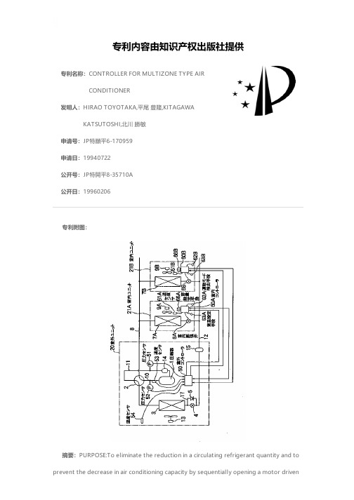
专利名称:CONTROLLER FOR MULTIZONE TYPE AIRCONDITIONER发明人:HIRAO TOYOTAKA,平尾 豊隆,KITAGAWAKATSUTOSHI,北川 勝敏申请号:JP特願平6-170959申请日:19940722公开号:JP特開平8-35710A公开日:19960206专利内容由知识产权出版社提供专利附图:摘要:PURPOSE:To eliminate the reduction in a circulating refrigerant quantity and to prevent the decrease in air conditioning capacity by sequentially opening a motor drivenexpansion valve of an indoor unit during pausing to the opening for feeding a small flow rate until the insufficient state is obviated according to a priority order when insufficiency of the circulating refrigerant quantity is judged. CONSTITUTION:A multizone type air conditioner has two indoor units connected in parallel with one outdoor unit in such a manner that the indoor units are individually operated and the detected values of suction, discharge pressures, a discharge tube temperature, etc., are input, and comprises gas down discriminating means 55 inputting the detected values of the suction, discharge pressures and the discharge tube temperature to discriminate whether a system is in gas down state or not. Fur conditioner also comprises priority order deciding means 56 for deciding the priority order of opening the expansion valves of the unit during pausing according to a room temperature deviation, an operation mode and an indoor unit capacity. When the refrigerant quantity is not insufficient, the expansion valves of the paused unit are fully closed in the decided order. When the quantity is insufficient, the valve of the unit is controlled to the opening for feeding a small flow rate until the insufficient state is avoided.申请人:MITSUBISHI HEAVY IND LTD,三菱重工業株式会社地址:東京都千代田区丸の内二丁目5番1号国籍:JP代理人:坂間 暁 (外1名)更多信息请下载全文后查看。
Multiroom air conditioner and control method there
专利名称:Multiroom air conditioner and controlmethod therefor发明人:Nishihara, Yoshikazu,Asada, Noriya,Ishikawa, Norimasa,Takahara, Tsutomu,Ao, Takahiko 申请号:EP00116247.8申请日:20000808公开号:EP1091178B1公开日:20061108专利内容由知识产权出版社提供摘要:The dehumidifying performance is enhanced. In dehumidifying operation, the air stream feel and cold wind feel for the inhabitants are suppressed. Dew condensation is prevented around the diffuser of the indoor unit. The individual temperature controllability of each indoor unit is excellent. The cost performance is excellent and it is inexpensive. A multi-room air conditioner includes one outdoor unit and a plurality of indoor units connected to the outdoor unit. In each indoor unit, the target control temperature is set and stored. Of the target control temperatures of the individual indoor units, in order to set the highest target control temperature at the control piping temperature, a control piping setting circuit is provided. The capacity of the compressor is controlled by comparing the control piping temperature and the piping temperature of the indoor unit adopted as the control piping temperature.申请人:MATSUSHITA ELECTRIC IND CO LTD地址:JP国籍:JP代理机构:Kügele, Bernhard 更多信息请下载全文后查看。
Multitronic控制系统-无热吸收干燥器实际操作状态图表说明书
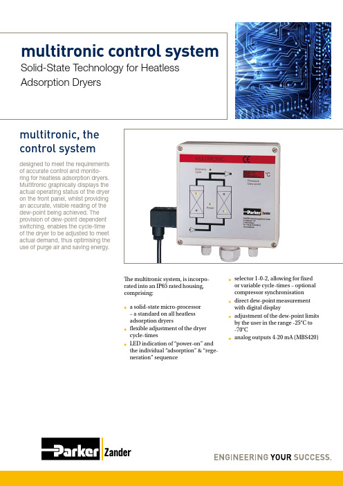
multitronic control system Solid-State Technology for Heatless Adsorption Dryersmultitronic, thecontrol systemdesigned to meet the requirementsof accurate control and monito-ring for heatless adsorption dryers.Multitronic graphically displays theactual operating status of the dryeron the front panel, whilst providingan accurate, visible reading of thedew-point being achieved. Theprovision of dew-point dependentswitching, enables the cycle-timeof the dryer to be adjusted to meetactual demand, thus optimising theuse of purge air and saving energy.The multitronic system, is incorpo-rated into an IP65 rated housing, comprising:a solid-state micro-processor– a standard on all heatless adsorption dryersflexible adjustment of the dryer cycle-timesLED indication of “power-on” and the individual “adsorption” & “rege- neration” sequence selector 1-0-2, allowing for fixed or variable cycle-times – optional compressor synchronisation direct dew-point measurement with digital displayadjustment of the dew-point limits by the user in the range -25°C to -70°Canalog outputs 4-20 mA (MBS420)multitronic, retrofittedThe moisture loading experienced by heatless adsorption dryers is subject to continuous fluctuation resulting from changes in demand, pressure and temperature. The multitronic solid-state microprocessor, in combination with a ZHM100 hygrometer copes with these changes by adjusting the cycle time to meet actual operating conditions, thus optimising the use of purge-air and saving energy.Changes to the operating input varia-bles directly affect the output variable, namely the provision of moisture-free compressed air, signified by the dew-point. The dew-point upper and lower changeover limits can be set by the user, within the range -25°C to -70°C. Once set, the multitronic control system takes over and automatically controls the adsorption cycle, varying this proportionally to the moistureAll heatless adsorption dryers with conventional control systems can be retrofitted with the multitronic system. In general, the regeneration of heatless adsorption dryers requires approx. 14% of the nominal flow at standard pressures and temperature to achieve a dew-point of -40°C. This value is often exceeded in practice. The act of “drying” is a physicalprocess and as such cannot be easily influenced, which is the reason why traditional obsolete control systems must be replaced by reliable, cost-ef-fective dew-point dependent systems such as multitronic.Energy OptimisationParker Zander provide a solution to the existence of dryers with obsolete control systems by providing a multi-loading as required. The regeneration cycle remains constant. Where variable load on the compressor is such that dew-point dependent cycling can take place, considerable energy savings can be achieved, resulting in a reduction of overall operating costs. At such a time, an LED on the front panel “Eco-nomy Cycle” indicates that the dryer is operating in energy-saving mode.Dew-point settings can be made by all customers be-tween -25°C und -70°C.The simple adjustment of the dew-point set-limits ensures that the com-pressed air required for regeneration (purge air) is only used as often as is required and not, in comparison with other systems to excess.tronic retrofit-kit, which can be easily installed on dryers from other ma-nufacturers. Retrofitting can achieve a pay-back of 2.5 months and less, depending upon size, flow-rate and operating parameters.The multitronic retrofit kit is available in two versions:a) multitronic PLUS retrofit kit - complete with hygrometer (pressure dew-point sensor), sensor-chamber and cable.b) M ultitronic BASIC retrofit kit - complete with multitronic control module with the possibility of connecting an existing hygrometer already in situ.multitronicthe control system, which pays dividends!The ideal dryers for retrofitting with multitronic, to achieve maximum savings, are those which demonstrate the following attributes:A dryer with a 10 minute cycle – with 12 re-pressurisation cycles per hour the energy requirement of a heatless adsorption dryer can be reduced by 5.6%, when compa- red with a dryer running a 6 minute cycleDryers with large condensate collection sump – increase the service-life of the adsorption mate- rial.Dryers utilising High-perfor- mance Adsorbants – desiccant material capable of coping with a wide range of operating parameters (pressures & temperatures) to achieve low, stable dew-points. Dryers with optimum valve functionality – direct-acting,normally-open main valves, ensure uninterrupted flow even in cases of power failure. Normally-closed exhaust-valves save energy by preventing the loss of treated compressed air.Dryers with aligned purge-air requirements – the “passive”-pre- setting of the purge air require- ment by the multitronic control system requires no purge-air adjustment for varing operating conditions, thus saving excessive purge-air wastage.multitronicThe control system, which pays dividends!Parker Zander Standard Adsorption DryersHigher capacities, operating pressures, inlet temperatures and lower pressure dew-points on request.BULMT-01-EN © 2011 Parker Hannifin Corporation. All rights reserved.E d . 2 0 1 1 -0 3 -0 3Europe, Middle East, Africa AE – United Arab Emirates,DubaiTel: +971 4 8127100********************AT – Austria, Wiener Neustadt Tel: +43 (0)2622 23501-0*************************AT – Eastern Europe, Wiener NeustadtTel: +43 (0)2622 23501 900**************************** AZ – Azerbaijan, BakuTel: +994 50 2233 458****************************BE/LU – Belgium, NivellesTel: +32 (0)67 280 900*************************BY – Belarus, MinskTel: +375 17 209 9399*************************CH – Switzerland, EtoyTel: +41 (0)21 821 87 00***************************** CZ – Czech Republic, Klecany Tel: +420 284 083 111******************************* DE – Germany, KaarstTel: +49 (0)2131 4016 0*************************DK – Denmark, BallerupTel: +45 43 56 04 00*************************ES – Spain, MadridTel: +34 902 330 001***********************FI – Finland, VantaaTel: +358 (0)20 753 2500*************************FR – France, Contamine s/Arve Tel: +33 (0)4 50 25 80 25************************GR – Greece, AthensTel: +30 210 933 6450************************HU – Hungary, BudapestTel: +36 1 220 4155*************************IE – Ireland, DublinTel: +353 (0)1 466 6370*************************IT – Italy, Corsico (MI)Tel: +39 02 45 19 21***********************KZ – Kazakhstan, AlmatyTel: +7 7272 505 800**************************** NL – The Netherlands, Oldenzaal Tel: +31 (0)541 585 000********************NO – Norway, AskerTel: +47 66 75 34 00************************PL – Poland, WarsawTel: +48 (0)22 573 24 00************************PT – Portugal, Leca da Palmeira Tel: +351 22 999 7360**************************RO – Romania, BucharestTel: +40 21 252 1382*************************RU – Russia, MoscowTel: +7 495 645-2156************************SE – Sweden, SpångaTel: +46 (0)8 59 79 50 00************************SK – Slovakia, Banská Bystrica Tel: +421 484 162 252**************************SL – Slovenia, Novo MestoTel: +386 7 337 6650**************************TR – Turkey, IstanbulTel: +90 216 4997081************************UA – Ukraine, KievTel +380 44 494 2731*************************UK – United Kingdom, Warwick Tel: +44 (0)1926 317 878********************ZA – South Africa, Kempton Park Tel: +27 (0)11 961 0700*****************************Parker WorldwideNorth AmericaCA – Canada, Milton, OntarioTel: +1 905 693 3000US – USA, ClevelandTel: +1 216 896 3000Asia PacificAU – Australia, Castle HillTel: +61 (0)2-9634 7777CN – China, ShanghaiTel: +86 21 2899 5000HK – Hong KongTel: +852 2428 8008IN – India, MumbaiTel: +91 22 6513 7081-85JP – Japan, TokyoTel: +81 (0)3 6408 3901KR – South Korea, SeoulTel: +82 2 559 0400MY – Malaysia, Shah AlamTel: +60 3 7849 0800NZ – New Zealand, Mt WellingtonTel: +64 9 574 1744SG – SingaporeTel: +65 6887 6300TH – Thailand, BangkokTel: +662 186 7000-99TW – Taiwan, TaipeiTel: +886 2 2298 8987South AmericaAR – Argentina, Buenos AiresTel: +54 3327 44 4129BR – Brazil, Sao Jose dos CamposTel: +55 800 727 5374CL – Chile, SantiagoTel: +56 2 623 1216MX – Mexico, ApodacaTel: +52 81 8156 6000EMEA Product Information CentreFree phone: 00 800 27 27 5374(from AT, BE, CH, CZ, DE, DK, EE, ES, FI, FR, IE, IL,IS, IT, LU, MT, NL, NO, PL, PT, RU, SE, SK, UK, ZA)US Product Information CentreToll-free number: 1-800-27 27 537 Your local authorized Parker distributor。
可以控制天气的空调作文
可以控制天气的空调作文英文回答:Through advancements in technology, the introduction of air conditioners that can manipulate the weather has become a reality. These innovative devices possess the capability to adjust temperature, humidity, and even atmospheric conditions, providing users with unprecedented control over their indoor environments.1. Temperature Regulation: These air conditioners employ advanced cooling and heating systems that can precisely adjust the temperature of a room. Users can effortlessly set desired temperatures through remote controls or intuitive touchpads, ensuring optimal comfort levels throughout the space.2. Humidity Control: By incorporating dehumidification and humidification features, these air conditioners can effectively manage the humidity levels in a room. They canremove excess moisture during humid conditions, creating a refreshing and breathable atmosphere. Conversely, they can also add moisture to dry environments, preventing discomfort and dryness.3. Air Purification: Advanced air conditioners are equipped with sophisticated filtration systems that capture dust, pollen, and other airborne particles. By circulating filtered air throughout the room, they improve indoor air quality, reducing allergens and promoting a healthierliving environment.4. Adjustable Wind Speed: These air conditioners offer versatile wind speed settings, allowing users to customize airflow according to their preferences. They can select gentle breezes for a soothing atmosphere or higher wind speeds for efficient cooling or heating.5. Atmospheric Customization: Some models even provide the ability to simulate different atmospheric conditions. They can create the ambiance of a breezy seaside retreat or a cozy mountain lodge, transporting users to desiredenvironments with just a few clicks.中文回答:1. 温度调节,这些空调采用先进的制冷和制热系统,可以精确调节房间温度。
天气控制器作文提纲
天气控制器作文提纲英文回答:Introduction:Briefly introduce the topic of weather controllers and their importance in our daily lives.Body:1. Definition and functions of weather controllers:Explain what weather controllers are and how they work.Discuss their main functions, such as regulating temperature, humidity, and air quality.2. Advantages of weather controllers:Discuss how weather controllers can improve our comfortand well-being.Explain how they can help save energy and reduce electricity bills.Highlight their role in preventing health issuesrelated to extreme weather conditions.3. Types of weather controllers:Discuss different types of weather controllersavailable in the market, such as thermostats, humidifiers, dehumidifiers, and air purifiers.Explain the specific functions and benefits of each type.4. Smart weather controllers:Discuss the emergence of smart weather controllers that can be controlled remotely through smartphones or voice assistants.Highlight the convenience and flexibility offered by these devices.5. Environmental impact:Discuss the environmental impact of weather controllers, particularly in terms of energy consumption and carbon emissions.Suggest ways to mitigate the negative impact, such as using energy-efficient models and optimizing their usage.6. Future developments:Discuss potential advancements in weather controller technology, such as integration with smart home systems and artificial intelligence.Highlight the potential benefits and challenges associated with these advancements.Conclusion:Summarize the importance of weather controllers in regulating our indoor environment and improving our quality of life.Encourage the adoption of energy-efficient and environmentally friendly weather controllers.中文回答:引言:简要介绍天气控制器的主题及其在我们日常生活中的重要性。
如何净化房内空气英语作文
如何净化房内空气英语作文Title: Purifying Indoor Air: A Comprehensive Guide。
In the modern era, where indoor living is prevalent, ensuring the purity of indoor air is paramount for maintaining good health and well-being. Poor indoor air quality can lead to various health issues, including respiratory problems, allergies, and even more severe conditions. Therefore, adopting effective methods to purify indoor air is essential. In this essay, we will explore various techniques and strategies to achieve clean and healthy indoor air.1. Regular Ventilation: Proper ventilation is the foundation of indoor air quality. Opening windows and doors to allow fresh air to circulate helps in diluting indoor pollutants and maintaining a healthy environment. Additionally, installing exhaust fans in kitchens and bathrooms can efficiently remove moisture and airborne contaminants.2. Air Purifiers: Air purifiers are devices designed to remove contaminants from the air. They utilize filters to capture particles such as dust, pollen, pet dander, and even some volatile organic compounds (VOCs). High-efficiency particulate air (HEPA) filters are particularly effective in capturing small particles, making them a popular choice for air purifiers.3. Houseplants: Certain indoor plants have air-purifying properties and can act as natural filters. Plants such as spider plants, peace lilies, and snake plants can help remove toxins from the air and improve overall air quality. Incorporating these plants into indoor spaces not only enhances aesthetic appeal but also contributes to a healthier living environment.4. Control Humidity: Maintaining optimal humiditylevels is crucial for indoor air quality. High humidity can promote mold growth and worsen respiratory issues, while low humidity can lead to dryness and discomfort. Using dehumidifiers in damp areas and humidifiers in dryenvironments can help regulate humidity levels and create a more comfortable and healthy indoor atmosphere.5. Avoid Smoking Indoors: Tobacco smoke contains numerous harmful chemicals that can linger in indoor environments long after smoking has ceased. Implementing a strict no-smoking policy indoors is vital for preservingair quality and protecting the health of occupants.6. Regular Cleaning: Dusting, vacuuming, and mopping surfaces regularly can significantly reduce the buildup of dust, pet hair, and other allergens in indoor spaces. Paying special attention to areas prone to accumulation, such as carpets, upholstery, and curtains, can helpmitigate indoor air pollutants.7. Limit Chemical Use: Many household products, such as cleaning agents, paints, and air fresheners, contain volatile organic compounds (VOCs) that can contribute to indoor air pollution. Opting for environmentally friendly and low-VOC alternatives or using these products in well-ventilated areas can minimize their impact on indoor airquality.8. Air Quality Monitoring: Investing in air quality monitoring devices can provide valuable insights into the levels of indoor pollutants and help identify areas for improvement. These devices measure parameters such as particulate matter, VOCs, carbon dioxide, and humidity, enabling homeowners to take appropriate actions to maintain healthy indoor air.In conclusion, achieving clean and healthy indoor air requires a multi-faceted approach involving ventilation, filtration, humidity control, and lifestyle modifications. By implementing the strategies outlined above, individuals can create indoor environments that promote well-being and enhance quality of life. Ensuring good indoor air quality is not only essential for physical health but also contributes to a more comfortable and enjoyable living space.。
Parker Davis 空调遥控器使用手册说明书

INFRARED WIRELESS MULTI-FUNCTIONREMOTE CONTROLLEROWNER’S MANUALRead through and understand these instructions thoroughly before attempting to operate your new air conditioning unit using this remote. Be sure to store this manual for future reference.The design and specifications of this product are subject to change without prior notice as development continues. Consult with thesales agency or manufacturer for details.is a registered trademark of Parker Davis HVAC International, Inc.Parker Davis HVAC International, Inc. 3250 NW 107th Ave, Doral, FL 33172USA Tel.: (305) 513-4488Fax: (305) 513-4499e-mail:****************Website: Table of ContentsRemote Controller Specifications (2)Button Layout and Functions (3)Handling the Remote Controller (4)LCD Screen Icons and Indicators (5)Basic Functions (6)Advanced Functions (13)Note:• T he layout of the buttons on this remote as depicted here is for the standard model. The actual model purchased mayvary slightly from these illustrations.•The signal output sent by this remote controller is processed entirely by the receiving air conditioning system. In the case that any of the functions of the remote are not available for the specific model of the air conditioning unit, thosefunctions will not work.•Your air conditioning unit’s user manual may have additional information regarding the usage of this remote controller.Notice:This device complies with all relevant national regulations.• For Canada, this device is compliant with CAN ICES-3(B)/NMB-3(B).• For the USA, this device is compliant with section 15 of FCC law.Operation is subject to two conditions:(1) This device may not cause harmful interference, and(2) This device must accept any interference received, includinginterference that may cause undesired operation.This equipment has been tested and found to comply within the limits for a Class B digital device, pursuant to section 15 of FCC law. These limits are designed to provide reasonable protection against harmful interference in a residential installation. This equipment generates, uses, and can radiate radio frequency energy and, if not installed and used in accordance with these instructions, may cause harmful interference to radio communications. However, there is no guarantee that interference will not occur in a particular installation. If this equipment does cause harmful interference to radio or television reception, which can be determined by turning the equipment off and on again, the user is encouraged to try and correct the interference by using one or more of the following measures:• Re-orient or relocate the receiving antenna.• Increase the separation distance between the equipment and receiver.• Connect the equipment to an outlet on a different circuit from that which the receiver is currently connected.• Consult the dealer or an experienced radio/TV technician for help.Changes or modifications not approved by the party responsible forcompliance could void the user’s authority to operate the equipment.Before using your new air conditioner , be sure to familiarize yourself with the remote control. The following is a brief overview of the remotecontroller itself. For instructions on how to operate your air conditioner , refer to the BASIC and ADVANCED functions sections of this manual.Note: HEAT mode is not supported by your appliance if you havepurchased a cooling-only version. The HEAT mode option on this controller will not function with cooling-only appliances.Not sure what a function does?Refer to the BASIC FUNCTIONS and ADVANCED FUNCTIONS sections of this manual for detailed descriptions on operating your air conditioner .may differ slightly from theillustrations and examples shown.• If the indoor unit does not have a particular function, the function selection on the remote will have no effect.with two AAA batteries, whichshould be inserted into the remote.• Remove the back cover from the remote to expose the battery compartment.• Insert the batteries, payingattention when matching the (+) and (-) ends of the batteries withthe symbols in the compartment.may or may not have been includedwith your unit) can be attached to a wall or stand. Check that the air conditioner is receiving signals before installation. Use the twoincluded screws to install the holder .• Do not mix old and newbatteries, or ones of different types.• Do not leave batteries in a remote that will not be used for more than 2 months.• The remote controller should be used within 8 meters of the unit.• The unit will beep whensignals from the remote are received.• Curtains, direct sunlight, etc. can interfere with the receiver’s infrared signal.• If the remote controller will not be used for more than 2 months, be sure to remove its batteries.Do not dispose of batteries as unsorted municipal waste. Refer to your local laws for the proper disposal of batteries.ON/OFFTurns the unit on or off.FANCycles through fan speeds in the following order:AUTO LOW MED HIGHHold this button for 2 seconds to activate silent mode.SWINGStarts/stops the horizontal louver auto-swing feature.TURBOSets the unit to reach the preset temperature in the shortest time.MODECycles through thefollowing operation modes:AUTO>COOL>DRY>HEAT>FAN ECOActivates Eco mode which saves energy during operation.OKUsed to confirm selected functions.TIMERSets the timer for turning the unit on or off. See the BASICfunctions section for instructions.SHORTCUTUsed to restore the current settings or to resume previous settings.CLEANUsed to stop/start self-clean mode.LEDTurns the indoor unit’s LED display and speaker on or off.SETScrolls through the functional settings as follows: FRESH>SLEEP>FOLLOW ME>AP MODE 1213341110678914512TEMPLowers temp. in 1˚ increments.Min 62˚F (17˚C).Battery DisposalThe remote controller goesinto the holderTEMPRaises temp. in 1˚ increments.Max 86˚F (30˚C).select COOL mode.2. Set your desired temperature using the temp or temp buttons.3. Press the FAN button to select the fan speed.4. Press the ON/OFF button to start the unit.The operating temperature range for your air conditioning unit is 62-86°F (17-30°C). You can increase or decrease this settemperature in 1° increments.Information is displayed when the remote controller powers up. An overview of the various icons is given below.Note: All indicators shown in the figure above are for the purpose of clear presentation. During actual operation, only the relative functionalicons will show on the display window.In AUTO mode, the unit willautomatically select COOL, FAN, HEAT , or DRY modes based on the set temperature.1. Press the MODE button to select AUTO mode.2. Set your desired temperature using the temp or temp buttons.3. Press the ON/OFF button to start the unit.Note: Fan speed can’t be set when in AUTO mode.Follow Me Feature Active Sleep Mode ActiveFresh Feature Active (some units)using FAN mode.LOW MED HIGH AUTOselect FAN mode.2. Press the FAN button to select the fan speed.3. Press the ON/OFF button to start the unit.Note: A temperature cannot beset when in FAN mode. As a result, your remote control’s LCD screen will not display the temperature.1. Press the MODE button to select AUTO mode.2. Set your desired temperature using the temp or tempbuttons.3. Press the ON/OFF button to start the unit.Note: Fan speed can’t be set when in DRY mode.1. Press the MODE button to select HEAT mode.2. Set your desired temperature using the temp or temp buttons.3. Press the FAN button to select the fan speed.4. Press the ON/OFF button to start the unit.Note: As the outdoor temperaturedrops, the performance of your unit during HEAT mode may be affected. In suchinstances, it is recommended to use an additional heatingappliance in conjunction with this air conditioner .Freeze Protection (FP) mode will fix the set temperature at 8°C/46°F while operating the system at high fan speed and the compressor on.Note: This function is for heat pump systems only.Press the arrow 2 times in 1 second whilst in HEAT mode and at a set temperature setting of 62°F in order to activate the FP function.Pressing On/Off, Mode, Fan, or Temp. buttons will cancel this function.910Your air conditioning unit has two timer-related features:• TIMER ON - Sets the amount of delay before the unit will automatically turn on.• TIMER OFF - Sets the amount of time before the unit will turn itself off.TIMER ON:The TIMER ON feature allows you to set a fixed period of time, after which the unit will automaticallyturn itself on. For example, it can be scheduled to turn on when the user arrives home from work.1. Press the TIMER button. The timer on indicator and the time amount will display.Note: This value indicates the amount of time left before the unit turns itself on.Activating TIMER ON with a value of 2h at 1 p.m. will turn the unit on at 3 p.m.2. Press the temp or temp buttons repeatedly to configure the time that the unit should turn itself on.3-4. After 1 second=, the TIMER ON feature will be active. Thedigital display on your remote controller will then return to displaying the temperature.The indicator remains on and thefeature is now activated.to turn on after 2.5 hours.to turn off after 5 hours.TIMER OFF:The TIMER OFF feature allows you to set a fixed period of time, after which the unit will automaticallyturn itself off. For example, it can be scheduled to turn off when the user leaves home for work.1. Press the TIMER button. The timer off indicator and the time amount will display.Note: This value indicates the amount of time left before the unit turns itself off.Activating TIMER OFF with a value of 5h at 2 p.m. will turn the unit off at 7 p.m.2. Press the temp or temp buttons repeatedly to configure the time that the unit should turn itself off.3-4. After 1 second, the TIMER OFF feature will be active. Thedigital display on your remote controller will then return to displaying the temperature.The indicator remains on and the feature is now activated.Note: When configuring the TIMER ON or TIMER OFF features, the configuration process will increase/decrease in 30 minute increments until the value reaches 10 hours. After 10 hours, the configuration will increase/decrease in 1 hour increments. Either function can be turned off by setting the timer to “0hr”. 24 hr limit max.331112Setting TIMER ON andTIMER OFF simultaneously:Users are able to configure both the ON and OFF settings of the timer function. Be sure to note that the time periods that are set for either of the functions are the amount of hours after the current time.Ex: If the current time is 1 p.m., and the user wants the system toturn itself on at 3:30 p.m. and run for 5 hours, do the following:Configure the TIMER ON feature of the system to turn itself on in 2.5 hours:Configure the TIMER OFF feature of the system to turn itself off in 5 hours:The example on page 11 shows how to set the system to turn on after 2.5 hours, operate for 5 hours, and then turn itself off. See the figure below:The remote display will be as shown:Note: If the user wishes to incorporate the scheduling feature, which will enable the ability to set specific times of each day of theweek where the unit will turn off and on, they may purchase the Pioneer Wireless Internet Access & Control Module. This accessory is sold seperately, and is available at .Current time 1PM2:00PM 3:00PM 4PM 5PM 6PM2.5 hours later 5 hours later3:30PM1314The ECO button is used to enter the system’s energy-efficient mode.When the unit is in cooling mode, pressing this button will adjust the temperature to 75°F (24°C) and the fan speed will change to AUTO.If the current set temperature is set above 75°C/24°C, then the fan speed will be changed to AUTO and the set temperature will not change.Note: Pressing the ECO button, or modifying the mode/adjusting the set temperature to below 75°C/24°C will take the system out of ECO mode.When in ECO mode, the temperature should be set to 75°C/24°C orgreater . If this results in insufficient cooling and discomfort, the ECO button should be pressed again to take the system out of ECO mode.Holding the FAN button for 2 seconds will activate/de-activate silent mode.This feature is only available to certain models. Use this feature to run the system more quietly. When running in this mode, the systemmay experience a diminished heatingor cooling output capacity.This is used to restore current settings or to resume previous settings. Push the shortcutbutton when the remote control is on and the system willautomatically revert back to its previous settings, such as itsoperating mode, set temperature,fan speed level, and the unit’s sleep mode feature (if active).If held for more than 2 seconds,the system will automatically restore its current operatingsettings in use at the time.Airborne bacteria can manifest in the moisture that condenses in or around the unit’s heat exchanger .With regular use, most of this moisture has usually evaporated.When self-clean mode is active,the system will clean itself and afterwards will turn itself off automatically. This feature can be used as often as needed, but is only available in COOL (AUTO),or DRY mode.Turbo mode forces the unit to reach the set temperature in the quickest time possible. In cooling mode, this will result in the unit jump-starting the process with strong wind output. In heating mode, the unit may employ the use of a supplementary electric heater , for units that are equippedwith this feature.Press the SET button to cycle through various operational functions as shown below. The buttons can also be used to scroll through the e the same procedures below to cancel the selected function.Press the SET button to cycle through the various operational functions as follows:Use the SET button to scroll to Sleep mode feature. Sleep mode is typically meant for periods of lower cooling requirements, such as during typical sleeping hours. This mode will result in decreased energy use, and can only be activated via remote control.For more details, please refer to the “sleep mode” section of the system user manual.Note: Sleep mode is unavailable during FAN or DRY mode.Press the turbo button and the self-clean button together for five seconds to lock or unlock the remote’s button board.The “Follow Me” button enables the remote controller to measure the temperature at its current location and send this value to the air conditioning system every 3 minutes. When using AUTO,COOL, or HEAT mode, prioritizing the temperature nearest to the user may ensure better comfort.Press and hold TURBO for 7 sec.to start/stop Follow Me memory in the event of system restart.Hold this button for 2 seconds to activate sleep modetogether for 1 second to lock the remote from being used.Follow Me AP ModeSleep Mode Fresh Feature (optional - to activate a supplemental ionizer for purification)。
多功能窗户,的作文,400字

多功能窗户,的作文,400字英文回答:Multi-functional windows are becoming increasingly popular in modern architecture due to their numerous benefits. They offer a wide range of features and advantages that enhance the comfort, energy efficiency, and aesthetic appeal of buildings.One of the most significant advantages of multi-functional windows is their ability to regulate natural light and heat gain. By incorporating advanced glazing technologies, these windows can effectively control the amount of sunlight that enters a space, reducing glare and heat buildup while maintaining ample natural light. This not only improves occupant comfort but also reduces the need for artificial lighting and air conditioning,resulting in energy savings.Multi-functional windows also play a crucial role inenhancing indoor air quality. They incorporate innovative ventilation systems that allow for controlled airflow, ensuring a healthy and fresh indoor environment. Byfiltering pollutants and allergens, these windowscontribute to the well-being of occupants, reducing respiratory problems and improving overall health.Furthermore, multi-functional windows offer a highlevel of durability and security. They are typically constructed with robust materials such as aluminum or PVC, ensuring longevity and resistance to wear and tear. The integration of tempered glass and advanced locking systems provides enhanced protection against break-ins and other security threats, creating a safe and secure living environment.In addition to their functional advantages, multi-functional windows also enhance the aesthetic appeal of buildings. Their sleek designs and customizable optionsallow architects to incorporate them seamlessly into a wide range of architectural styles. From classic to contemporary, these windows add a touch of elegance and modernity to anybuilding facade.Overall, multi-functional windows offer a comprehensive solution for modern living. They combine comfort, energy efficiency, indoor air quality, durability, and aesthetic appeal, creating a more sustainable, healthy, and enjoyable indoor environment for occupants.中文回答:多功能窗户因其众多优势而在现代建筑中越来越受欢迎。
柔性空调系统兼容性表说明书
INDOOR UNIT
38MARBQ12AA3
58S(B,C)*A045E14**12
B•‡
58S(B,C)*A045E17**12
C•‡
58S(B,C)*A070E14**12
B•‡
58S(B,C)*A070E17**12
58S(B,C)*A070E17**16
C•‡
58S(B,C)*A070E21**16
38MBQB36---3 38MBRQ36A--3 38MBRBQ36AA3 38MBRCQ36AA3
38MBQB48---3 38MBRQ48A--3 38MBRBQ48AA3 38MBRCQ48AA3
38MBRQ58A--3 38MBRCQ58AA3
● ●
● ● ●
● ● ●
● Only 38MBRB/C ● Only 38MBRB/C ●
3
Compatibility Single Zone Hybrid Solutions – Performance® Series...............................................................................
4-5
Compatibility Single Zone – Comfort® Series..................................................................................................................
Edition Date: 07/2022 Page 3
Catalog No: CAR-DLSS-12CC Replaces: CAR-DLSS-11CC
NuAire 药剂房兼容的生物安全柜和流动空气工作站说明书
NuAire, Inc. | 2100 Fernbrook Lane | Plymouth, MN 55447 |U.S.A. | MEDICATION WORKFLOW COMPATIBLEBIOSAFETY CABINETS AND LAMINAR AIRFLOW WORKSTATIONSSterile Hazardous Containment Primary Engineering Control (C-PEC)[A][B][C]IV Workflow Compatible Laminar Airflow Workstation (LAFW)TheNU-240 is designed as a table top clean bench that features the newesttechnologies in laminar airflow design, materials and manufacturingprocesses. The clean workstation can be used where clean airflow per ISO14644-1 is required for the preparation of injectable drugs, Itissue culture, optics, microelectronics, etc. The clean workstation isused to protect work product from contamination. The clean workstationis available with an optional base stand, placing the work surface at 30”(762mm) or 36” (914mm). A significant number of design innovations givethe NuAire Laminar flow equipment superior performance qualities inairflow, lighting, noise levels and vibration.Sterile Hazardous[B][C]The back wall features acut out with glass inlay fits acomputer monitor for greateraccessibility and usability of NU-543FeaturesSpecificationsLeft ViewTop ViewDepthFront ViewHeightWidthInterior11Air In-flow 70% Recirculated vs. 30% ExhaustedHEPA Filtered AirAir SplitContaminated Worksurface Air Contaminated Room Air LabGard NU-543 Biosafety CabinetModel Width Size(nominal)Electrical* (all sizes)Interior Dimensions (W x D x H) [mm]Exterior Dimensions (W x D x H) [mm]Net Weight NU-543-300 3 ft [0.9 m]115 VAC / 60 Hz E: 230 VAC / 50 - 60 Hz 34 3/8 x 25 3/4 x 28 1/2[873 x 654 x 724]41 5/8 x 31 7/16 x 60 7/8[1057 x 799 x 1546]410 lbs [186 kg]NU-543-400 4 ft [1.2 m]46 3/8 x 25 3/4 x 28 1/2[1178 x 654 x 724]53 5/8 x 31 7/16 x 60 7/8[1362 x 799 x 1546]480 lbs [218 kg]NU-543-500 5 ft [1.5 m]58 3/8 x 25 3/4 x 28 1/2[1483 x 654 x 724]65 5/8 x 31 7/16 x 60 7/8[1669 x 799 x 1546]570 lbs [258 kg]NU-543-6006 ft [1.8 m]70 3/8 x 25 3/4 x 28 1/2[1788 x 654 x 724]77 5/8 x 31 7/16 x 60 7/8[1972 x 799 x 1546]640 lbs [290 kg]Performance Specifications:30% exhausted / 70% recirculatedDynamic air barrier of 105 fpm (0.53 m/s) inflow separating pharmacy from work zone environment True Laminar Unidirectional Down-flow air of 60 fpm (0.30 m/s) for minimal cross contamination 300% Filter Load Capacity (±10 Year Average depending on pharmacy environment)Standard Features:FlowGard Electronic Control System IntelliFlow Airflow Control System Energy Saver (ES) DC/ECM Motor Internal Exhaust DampenerMonolithic Pressure Tight Design (Silicone Free)HEPEX Zero Leak Airflow Front Filter RemovalPermanent Plenum with Quick Release Supply Filter 3” (76 mm) Metal Frame Supply HEPA Filter 99.99% @ 0.3 Microns (NSF/ANSI 49)12” (305 mm) Metal Frame Exhaust HEPA Filter 99.99% @ 0.3 Microns (NSF/ANSI 49)3” (76 mm) Metal Frame Supply HEPA (H14) Filter 99.995% MPPS (E Model)12” (305 mm) Metal Frame Exhaust HEPA (H14) Filter 99.995% MPPS (E Model)10” [254 mm] Access Opening (NSF/ANSI 49, EN12469) Frame-less Sliding Tempered Glass View Screen External Fluorescent Lighting Ergonomic Plastic ArmrestRemovable Work TrayMetal Diffuser Over Supply Filter Spill Trough with Drain ValveTwo (2) Duplex Outlets Back Wall (3 Amp Max)One (1) Service Valve Right Side Wall One (1) Service Coupling Right Side Wall Two (2) Service Couplings Left Side Wall 12 ft [2.5 m] Power CordOptional F eatures & Accessories:IV Bar with 3 locations & 6 Stainless Steel Hooks Exhaust Transition CanopyBase Stand- Telescoping Base Stand- Telescoping OSHPD OPM Rated* - Telescoping Base Storage - MotorizedBase Stand Options - Leg Levelers - Casters - 8” (203 mm) Shelf** - 12” (305 mm) Shelf** - Ergotron ® Monitor & Keyboard Mount *Leg Levelers Only**Telescoping Base Stand Only12” [305 mm] Access Opening (NSF/ANSI 49)8” [203 mm] Access Opening (NSF/ANSI 49)Ultraviolet Light LED LightingStorage Pull-Out Trays Decorative Side Panels Stainless Steel Armrest GFI Outlets Plumbing Options: - Soft Copper - Black Pipe- Rigid CopperOutlet Options:- Two (2) GFI Duplex Outlets Back Wall (3 Amp Max) - Two (2) GFI Duplex Outlets Back Wall (5 Amp Max) - Two (2) Duplex Outlets Back Wall with Dedicated Power Cord (15 Amp Max) - Two (2) GFI Duplex Outlets Back Wall with Dedicated Power Cord (15 Amp Max) - Two (2) Duplex Outlets Back Wall with Dedicated Power Cord (20 Amp Max)- Two (2) GFI Duplex Outlets Back Wall with Dedicated Power Cord (20 Amp Max)- Front Faring Outlets Prop-up Stand for Work TrayStainless Steel Window Edge ProtectorNSF Approved Cord Pass Through (Right and/or Left Sidewall) Smooth Interior Sidewalls NSF Approved Backwall Cutout for Monitor Custom SolutionsIV Bar with Six HooksHang IV bags in the sterile work zone. Three IV bar height locations optimize workflow process.[B][A]Assist your cleaning efforts cut out with glass inlay fits a computer monitor for greater accessibility and usability of [C]Options/The (BSC)operation as a console model. The LabGard ES model NU-560 utilizes an Energy Saver DC ECM motor optimally determined forward curved fan for each model size/width to maximize both energy efficiency and filter loading capacity. The Energy Saver ECM motor is controlled to airflow setpoints via a solid-state DC motor controller with digital dual thermistor airflow sensors that provide an automatic compensation (constant volume control) for both filter loading and line voltage variances.SHARE A PICTURE AND TAG YOUR NUAIRE PHARMACY EQUIPMENT USING #MYNUAIREFor more information please visit or call 1.763.553.1270Request a Quote© Copyright 2019. NuAire, Inc. All Rights Reserved. 20-1403-B-D-EN-5-1118Y our Local NuAire Partner。
空调中英文对照表
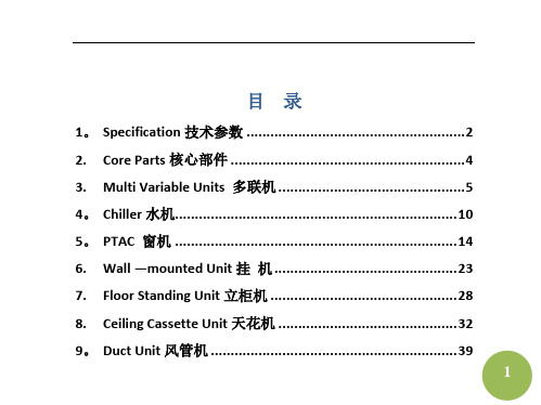
目录1。
Specification技术参数 (2)2. Core Parts核心部件 (4)3. Multi Variable Units 多联机 (5)4。
Chiller水机 (10)5。
PTAC 窗机 (14)6. Wall —mounted Unit挂机 (23)7. Floor Standing Unit立柜机 (28)8. Ceiling Cassette Unit天花机 (32)9。
Duct Unit风管机 (39)110。
................................................. F loor &Ceiling Unit座吊机4311. Electronic Control电控 (47)1.Specification技术参数1.1.Indoor Air Inlet DB(dry bulb)Temp 室内进风干球温度1.2.Indoor Air Inlet WB (wet bulb)Temp 室内进风湿球温度1.3.Outdoor Air Inlet DB Temp 室外进风干球温度1.4.Outdoor Air Inlet WB Temp 室外进风湿球温度1.5.Indoor Air Outlet DB Temp 室内出风干球温度1.6.Indoor Air Outlet WB Temp 室内出风湿球温度1.7.Static Pressure静压1.8.Pressure Difference压差21.9.Airflow Volume风量1.10.Dimension 尺寸1.11.Noise Level 噪音等级1.12.Return Air Temp回气温度1.13.Discharge Air Temp排气温度1.14.Enthalpy Difference焓差1.15.Dehumidification除湿1.16.Sensible Heating Capacity显热量tent Cooling Capacity 潜在制冷量1.18.Total Heating Capacity总制热量1.19.COP能效比1.20.Rated Voltage额定电压1.21.Rated Current额定电流1.22.Rated Power Input额定输入功率1.23.Frequency频率31.24.Refrigerant Charge 冷媒充注 Weight 净重1.26.Gross Weight 毛重1.27.Model 型号2.Core Parts核心部件pressor压缩机2.2.Condenser冷凝器2.3.Throttle components节流部件2.4.Capillary毛细管2.5.4—way reversing valve四通阀2.6.Electronic expansion valve (EEV)电子膨胀阀2.7.Thermostatic expansion valve热力膨胀阀42.8.Evaporator蒸发器2.9.Vapor—liquid separator气液分离器2.10.Electronic parts box(E-parts box)电控盒2.11.One-way valve单向阀3.Multi Variable Units 多联机3.1.Front panel前面板3.2.Ironclad asynchronous motor for outdoor unit异步铁壳室外电机3.3.Motor Bracket电机支架3.4.Front maintenance board前维修板3.5.Left side board左侧板3.6.Septum plate中隔板53.7.Welding assy for suction pipe回气管焊接组件3.8.Suction pipe回气管3.9.Oil return capillary transition tube回油毛细管过渡管3.10.Chassis assy底盘组件3.11.Chassis 底盘体3.12.Chassis foot底脚3.13.Chassis reinforced board底盘加强板3.1pressor压缩机3.15.One-way valve assy单向阀组件3.16.Connecting pipe for high pressure one—way valve高压单向阀连接管3.17.Filter过滤器3.18.One-way valve单向阀3.19.Valve seat assy阀座板组件3.20.Valve seat 阀座板63.21.Cut—off valve for two connecting pipes双接管截止阀DN133.22.Rear panel后面板3.23.Right side board右侧板3.2rge handle大抽手3.25.Protection grill 防护网3.26.Condenser prewelding assy冷凝器预焊组件3.27.Two—row condenser 两排冷凝器3.28.Condenser exhaust receiver welding assy 冷凝器集气焊接组件3.29.Current dividing capillary assy of condenser 冷凝器分流毛细管组件3.30.Condenser main outlet pipe 冷凝器总出管3.31.Fixing pipe of condenser main outlet pipe 冷凝器总出管固定管3.32.Adfluxion pipe assy汇流管组件73.33.Adfluxion pipe 汇流管3.34.DN8 Copper adapter with holder DN8带座铜接头3.35.Connecting pipe to low pressure valve低压阀连接管3.36.Electronic expansion valve assy 电子膨胀阀组件3.37.Electronic expansion valve 电子膨胀阀3.38.Plastic encapsulating coil塑封线圈3.39.Expansion valve capillary膨胀阀毛细管3.40.E—shape filter E型过滤器3.41.DN4 Copper adapter with holder DN4带座铜接头3.42.Filter for oil return pipe 回油管道过滤器3.43.4—way reversing valve assy四通阀组件3.44.4-way reversing valve四通阀3.45.4-way valve reversing coil assy四通阀线圈组件3.46.Discharge pipe assy 排气管组件3.47.Discharge pipe排气管83.48.Installation copper tube for probe探头铜管3.49.Oil return pipeline filter 回油管道过滤器3.50.Oil separator 油分离器3.51.Separator 分离器3.52.Top panel foam assy顶盖板贴棉组件3.53.Rear frame后边框3.54.Electronic control components电控部件3.55.Welding assy for E—parts box 电器盒焊接组件3.56.Cooling fin fixing board 散热片固定板3.57.Cooling fin散热片3.58.Main board assy for ourdoor unit室外主板组件3.59.Module board assy for outdoor unit室外模块板组件3.60.Module board transformer assy for outdoor unit室外模块板变压器3.61.Monophase filter单相滤波器93.62.Rubber ring橡胶圈(小过线圈)3.63.Amorphous inductor非晶电感3.64.Eliminator挡水板3.65.Small handle小抽手3.66.Propeller fan轴流风叶3.67.Plastic front net塑料前网罩4.Chiller水机4.1Front and rear support for wind inlet guide导风圈前后支撑4.2Front and rear support assy for fan风机前后支撑组件4.3Middle support assy for fan风机中支撑组件4.4Sealing board for condenser 冷凝器封板4.5Lateral support for wind inlet guide导风圈侧支撑104.6Front and rear beam前后横梁4.7Lateral beam assy侧横梁组件4.8Pipe clamp管夹4.9Fixing board for distributor分流头固定座4.10Trigonal board三角板4.11Condenser assy冷凝器部件4.12Water pan assy接水盘组件4.13Vertical shaft assy立柱组件4.14Evaporator干式蒸发器4.15Vapour—liquid separator汽液分离器4.16Compressor压缩机组件4.17Compressor support assy 压缩机支撑板组件4.18Support for vapour—liquid separator气分支架组件4.19Pipe support管支架4.20High-pressure switch高压开关114.21Suction pipe components 回气管部件4.22Low-pressure switch低压开关4.23Throttle componets 节流部件4.24Electronic expansion valve (EEV)电子膨胀阀4.25EEV coil电子膨胀线圈4.264—Way reversing valve components四通阀部件4.274-Way reversing valve coil 四通阀线圈4.28Pressure switch压力开关4.29Discharge pipe components排气管部件4.30Base assy底座组件4.31E—parts components电控部件4.32Current transformer电流互感器4.33Crankcase heater曲轴箱加热器4.34Adapter board for 4-way reversing valve四通阀转接板4.35Main control panel控制主板124.36Envirionment temperature sensor环境温度传感器4.37System water inlet temperature sensor系统进水温度传感器4.38System water outlet temperature sensor系统出水温度传感器4.39Unitary water outlet temperature sensor单元出水温度传感器4.40Fin temperature sensor翅片温度传感器4.41Fan capacitor风机电容4.42Alternating contactor交流接触器4.43Power terminal电源端子台4.44Main board transformer主板变压器4.45Engineering terminal工程端子台4.46Trigonal set sqare固定三角板4.47Compressor support assy 压缩机支撑板组件4.48Wire trough support线槽支架134.49Middle support for wind inlet guide导风圈中支撑4.50Vertical support for wind inlet guide导风圈纵支撑4.51Support assy for fan风机支架组件4.52Outdoor unit motor室外电机4.53Propeller fan轴流风叶5.PTAC 窗机5.1.Air filter防尘网5.2.Control panel cover操作盖板5.3.Front panel 前面板5.4.Self-locking switch自锁开关5.5.Connection bar连杆5.6.Horizontal louver水平导风条145.7.Heat—insulation foam for air-out出风口保温棉5.8.Scroll case base components风壳座部件5.9.Centrifugal fan离心风轮5.10.Fresh air inlet lever新风门连杆5.11.Fresh air inlet新风门5.12.Scroll case cover风壳盖5.13.Air deflector导风板5.14.Fixing board for vertical louver导风板固定板5.15.Capacitor clamp电容卡5.16.Capacitor cap电容帽pressor capacitor压缩机电容5.18.Motor电机5.19.Connecting board搭板5.20.Propeller fan轴流风叶5.21.Rear cover后盖板155.22.Rear brattice后围板5.23.Shutter clamp百叶窗夹5.24.Left shutter frame安装左框条5.25.Cabinet component外箱部件5.26.Upper shutter frame上框条5.27.Installation support 安装支撑5.28.Nut 螺母5.29.Bolt 螺栓5.30.Lower shutter frame下框条5.31.Right shutter frame右框条5.32.Shutter密封百叶5.33.Connection bar to cabinet外箱连接条5.34.Shutter locking bar 卡条5.35.Motor capacitor电机电容5.36.Temperature controller 温控器165.37.Main switch主令开关5.38.Knob旋钮5.39.Control panel控制面板5.40.Control box控制盒5.41.E—parts box电控盒5.42.Evaporator assy蒸发器组件5.43.Suction pipe assy回气管组件5.44.Capillary assy 毛细管组件5.45.Condenser output pipe冷凝器输出管5.46.Input pipe for evaporator蒸发器输入管5.47.Input pipe for condenser冷凝器输入管5.48.Condenser assy冷凝器组件pressor wiring cover nut压缩机接线盖螺母5.50.Washer for compressor wiring cover压缩机接线盖垫片pressor wiring cover压缩机接线盖175.52.Overcurrent protector for compressor压缩机过流保护器5.53.Wire to overcurrent protector过流保护器线体5.54.Sealing gasket for wiring cover接线盖密封片pressor压缩机5.56.Rubber cushion for compressor压缩机胶垫5.57.Fixinging nut for compressor压缩机固定螺母5.58.Fixing gasket for compressor 压缩机固定垫片5.59.Motor support 电机支架5.60.Chassis 底盘5.61.Fixing sheet for front panel 前面板固定片5.62.Front panel前面板5.63.Transformer变压器5.64.Transformer box变压器盒5.65.Display board assy显示板组件5.66.Main control board assy主控板组件185.67.Air-inlet board 进风孔板5.68.Evaporator base蒸发器底座5.69.Cover盖板5.70.Front brattice前围板5.71.Protecting clamp fro power cord电源线保护卡5.72.Protecting U—clamp for power cord 电源线保护圈5.73.Scroll case涡壳5.74.Air —out frame出风口5.75.Self lock switch自锁开关5.76.Cover for E—parts box电控盒盖板5.77.Left fixing plate for chassis底盘左固定板5.78.Right fixing plate for chassis 底盘右固定板5.79.Supporting bar for installation安装支承条5.80.Discharge pipe排气管5.81.Clamp for wires电线中间夹子195.82.Fixing board for E-parts box电控盒固定板5.83.Rear cover for control box线路板盖5.84.Power cord clamp电源线夹5.85.Front cover前盖板5.86.Long connecting board长搭板5.87.Rear cover后盖板5.88.Wind guiding board导流板5.89.Water proof rubber ring防水橡胶圈5.90.Rear rubber ring for motor电机后橡胶圈5.91.Front rubber ring for motor电机前橡胶圈5.92.Short connecting board短搭板5.93.Pin销5.94.Expansive core膨胀芯5.95.Fixing plate for chassis底盘固定板5.96.Installation support 安装支架205.97.Front panel components前面板部件5.98.Electronic control components电控部件5.99.Control box assy控制盒组件5.100.Installation parts 安装附件5.101.Remote controller遥控器5.102.Clamp for temp sensor温包卡5.103.Wind inlet guide导风圈5.104.Swing switch 摇摆开关5.105.Sychronous motor 同步电机5.106.Defrosting temp controller化霜温控器5.107.Rear side board 后侧板5.108.Adjusting bolt 调整螺栓5.109.Rubber plug 橡胶塞5.110.Sealing gasket 密封圈5.111.Drain hose出水接管215.112.Right lower fixing clamp for motor电机下压盖(右)5.113.Right upper fixing clamp for motor电机上压盖(右)5.114.Left upper fixing clamp for motor电机上压盖(左)5.115.Left lower fixing clamp for motor电机下压盖(左)5.116.Water pan接水盘5.117.Power cord电源线5.118.Wire joint二位接线座5.119.Frame fixing board面框固定板5.120.Drive gear传动轮5.121.Wire joint panel接线底板5.122.Heater cut—out assy热熔断器组件5.123.PTC heater PTC发热器226.Wall-mounted Unit挂机6.1.Front panel前面板6.2.Air filter防尘网6.3.Screw cap螺丝盖6.4.Panel frame面框6.5.Air cleaner复合式空气清新网6.6.Air cleaner upper cover 清新器上盖6.7.Window receiver 接收窗片6.8.LED indicator 显示灯镜6.9.Horizontal louver水平导风叶6.10.Upper horizontal louver导风条(上)6.11.Lower horizontal louver导风条(下)6.12.Vertical louver垂直导风叶6.13.Air out frame出风框236.14.Louver holder导风叶连杆6.15.Sychronous motor同步电机6.16.Drain hose出水喉6.17.Evaporator temp sensor assy蒸发器温度传感器组件6.18.Left holder for evaporator蒸发器左支板6.19.Evaporator 蒸发器6.20.Waterproof board assy挡水板组件6.21.Bearing holder轴承座6.22.Cross flow fan,assy贯流风轮组件6.23.Chassis底盘6.24.Rear cover for chassis底盘后盖板6.25.Installation plate for indoor unit室内机安装板6.26.Little installation plate小安装板6.27.Connecting pipe clamp配管固定卡6.28.Fan motor风机电机246.29.Motor cover电机盖6.30.E—parts box cover电控盒盖6.31.Indicator holder显示灯座6.32.Display board assy显示板组件6.33.Display board enclosure显示灯罩6.34.Main control board主电控板6.35.Transformer变压器6.36.E—parts box电控盒6.37.Wire clamp压线条6.38.Wire joint,5p小五位接线座组6.39.Remote controller遥控器6.40.Remote controller installation support assy遥控器安装支架组件6.41.Display panel 显示面板6.42.Relay holder继电器底座256.43.Protection box for relay 继电器保护盒6.44.Bush衬套6.45.Installation board for louver百叶安装板6.46.Wire clamp for power cord电线压条6.47.Relay继电器6.48.Switch board assy开关板组件6.49.Installation board base安装板座6.50.Fan capacitor风机电容6.51.Strengthening board for chassis底盘加强板6.52.Supporting board for chassis 底盘下板6.53.Fan wheel support风轮支架6.54.Louver connecting bar摇摆连杆6.55.Right support for evaporator蒸发器右支承6.56.Installation plate for main board电路板安装座6.57.Installation plate for wire joint接线座安装板266.58.Bear holder轴承座6.59.Control board assy控制面板组件6.60.Protecting plate防护片6.61.Air cleaner cover滤清器盖6.62.Right cover for motor电机右盖板6.63.Fixing clamp for motor电机固定卡6.64.Right cover for panel frame面框缺口封板6.65.Wind guide on chassis底盘导风板6.66.E—parts components电控部件6.67.Plug堵塞6.68.Lower clap for panel frame面框下卡扣6.69.Upper clap for panel frame面框上卡扣6.70.HEAP filter HEAP滤网6.71.Copper nut,TLM—A01铜螺母TLM-A016.72.Copper nut,TLM—B02铜螺母TLM—B02276.73.Sponge海绵6.74.Foam泡沫6.75.Right joint board of Evaporator蒸发器右连接板6.76.Right side board of front evaporator前蒸发器右边板6.77.Right side board of rear evaporator后蒸发器右边板7.Floor Standing Unit立柜机7.1.Air out frame assy出风框部件7.2.Conection bar for horizontal louver横导风条连杆7.3.Sealing foam for air outlet frame出风框边密封泡沫7.4.Display box assy显示控制盒部件7.5.Control box assy控制盒底座7.6.Front panel components前面板部件287.7.Sealing board密封板7.8.Cover components盖板部件7.9.Water pan components接水盘部件7.10.Evaporator蒸发器7.11.Inlet pipe assy for evaporator蒸发器输入管组件7.12.Outlet pipe for evaporator蒸发器输出管组件7.13.PTC eletric heating component PTC电加热部件7.14.Left side board component左侧板部件7.15.Top cover components顶盖部件7.16.Chassis components底盘部件7.17.E-parts box电器盒7.18.Fan motor capacitor电机电容7.19.Main control board assy主控板组件7.20.Electric heating control board assy电辅热辅助组件7.21.Transformer变压器297.22.Wire joint, 5p大五位接线座7.23.Wire clamp压线板7.24.Right side board components外箱右侧板部件7.25.Chassis底盘7.26.Fan motor for indoor unit室内风扇电机7.27.Drain pipe排水管7.28.Centrifugal fan离心风轮7.29.Wind inlet guide导风圈7.30.Wind inlet grille components进风格栅部件7.31.Air filter空气滤尘网7.32.Remote controller遥控器7.33.Indoor temp sensor室温传感器7.34.Pipe temp sensor管温传感器7.35.E—parts box cover电器盒盖7.36.Scroll case components涡壳部件307.37.Installation box for main board电路板安装盒7.38.Anion generator components负离子发生器部件7.39.Anion generator support负离子发生器支架7.40.Anion generator box负离子发生器盒7.41.Anion generator负离子发生器7.42.Right front board for evaporator蒸发器右侧前挡板7.43.Front panel前面板7.44.Motor holder电机座7.45.Electric heater assy电加热管电加热组件7.46.Lower cover for evaporator蒸发器下挡板7.47.Rubber underlay for motor电机减振橡胶垫318.Ceiling Cassette Unit天花机8.1.Water pan components接水盘部件8.2.Water drain plug排水塞8.3.Capacitor电容8.4.E-parts box assy电控盒组件8.5.E-parts box cover电控盒盖8.6.Transformer变压器8.7.Main control board 主控板组件8.8.Wind inlet guide导风圈8.9.Nut螺母8.10.Fan clamp风轮卡片8.11.Fan wheel components风轮部件8.12.Fan motor for indoor unit室内风扇电机8.13.Motor gascket电机钢垫328.14.Evaporator base component蒸发器底座部件8.15.Chassis底盘部件8.16.Wire clamp board压线板8.17.Sealing board for outlet pipe 出管密封板8.18.Installation hanger安装吊钩8.19.Expansion hanger膨胀吊钩8.20.Drain pump assy排水泵组件8.21.Water level sensor assy液位传感器组件8.22.Pumping pipe clamp 抽水管卡环8.23.Pumping pipe抽水管8.24.Pumping coupling抽水接管8.25.Separating board for water pump水泵挡板8.26.Rubber washerfor water pump水泵胶垫8.27.Installation support for water pump水泵安装架8.28.Panel components面板部件338.29.Installation cover安装盖板8.30.Cowling导风板8.31.Filter滤尘网8.32.Grille switch格栅开关8.33.Grille switch cover格栅开关盖8.34.Grille进风格栅8.35.Panel hanger assy面板吊钩部件8.36.Control box控制盒8.37.LED support灯架8.38.Display board assy显示板8.39.Control box cover控制盒盖8.40.Panel面板8.41.Backup plate for air out 出风口垫板8.42.Fixing hanger for evaporator蒸发器固定钩8.43.Inlet pipe assy for evaporator 蒸发器输入管组件348.44.Outlet pipe assy for evaporator 蒸发器输出管组件8.45.Evaporator components蒸发器部件8.46.Fixing board for evaporator蒸发器固定板8.47.Rubber O-ring for wire crossing过线胶圈8.48.Pipe temp sensor管温传感器8.49.Indoor temp sensor assy室温传感器组件8.50.Remote controller遥控器8.51.Coupling联轴器8.52.Bearing轴承8.53.Bearing holder轴承座8.54.Axis连接轴8.55.Electric throttle components电子节流部件8.56.Warning panel警示图电器板8.57.Circuit diagram panel线路图电器板8.58.Small wind inlet guide小导风圈358.59.E—parts components电控部件8.60.E-parts box welding assy电器盒焊接组件8.61.No.3 groove clamp 3号压线扣8.62.PTC transformer PTC变压器8.63.Fan capacitor风机电容8.64.Terminal of indoor unit室内端子台8.65.Electronic control board for indoor unit室内电控板8.66.E-parts box电器盒8.67.Water pan assy水盘组件8.68.Auxiliary fixing board for evaporator蒸发器副固定板8.69.Pre-assembling assy for evaporator main fixing board蒸发器主固定板预装组件8.70.Main fixing board for evaporator蒸发器主固定板8.71.Evaporator components蒸发器部件8.72.Evaporator baffle蒸发器挡板368.73.Evaporator 蒸发器8.74.Installation copper tube for probe探头铜管8.75.Current dividing assy for evaporator蒸发器分流组件8.76.Current collecting pipe assy for evaporator蒸发器集流管组件8.77.Insulating tube保温管8.78.Rubber insulating tube橡塑保温管8.79.Water pump水泵8.80.Liquid-level sensor液位传感器8.81.Water pump motor holder水泵电机座8.82.Underlay for water pump support水泵支架垫块8.83.Pre-assembling assy for upper foam上泡沫预装件8.84.Centrifugal fan离心风叶8.85.Hanger挂角8.86.Rear brattice后围板378.87.Pre-assembling assy for motor电机预装组件8.88.One—axis indoor motor(YDK-35Q-8P3)单轴室内电机(YDK-35Q—8P3)8.89.Motor foot underlay电机脚垫8.90.Chassis assy底盘组件8.91.Right side board右侧板8.92.Front brattice前围板8.93.Drain pipe joint排水管接头8.94.Side maintenance board for water pump水泵侧维修板8.95.Lower pipe clamp下管夹8.96.Upper pipe clamp上管夹8.97.Valve panel assy阀板组件8.98.Wire outlet frame 2出线护框28.99.Valve panel阀板8.100.Wire board压线板388.101.Left side board左侧板8.102.Water outlet pipe出水管9.Duct Unit风管机9.1.Air—out frame 出风口9.2.Front panel components前面板部件9.3.Evaporator蒸发器9.4.Input pipe assy输入管组件9.5.Output pipe assy输出管组件9.6.Pipe temp sensor assy of indoor unit室内管温传感器组件9.7.Panel assy面板9.8.Air filter防尘网399.9.Canvas passage 帆布风道9.10.Base board for evaporator 蒸发器下衬板9.11.Water pan components接水盘部件9.12.Cover for middle beam横梁上盖组件9.13.Middle beam welding assy中间横梁焊合件9.14.Chassis components底盘部件9.15.Left side board assy左侧板组件9.16.wire-crossing board assy过线板组件9.17.Cover for right side board右侧板盖板9.18.Capacitor box电容盒9.19.Capacitor电容9.20.E—parts box cover电控盒盖9.21.Installation support for remote controller遥控器安装架9.22.Remote controller遥控器9.23.Electronic control components电控盒部件409.24.Electric part box电控盒9.25.Wire joint接线座9.26.Transfomrer变压器9.27.Main control board assy主控板组件9.28.Right upper cover for motor电机上压盖(右)9.29.Right lower cover for motor电机下压盖(右)9.30.Motor baffle电机围板9.31.Right side board assy右侧板组件9.32.Left upper cover for motor电机上压盖(左)9.33.Left upper cover for motor电机下压盖(左)9.34.Fan wheel assy风轮组件9.35.Fan motor风扇电机9.36.Left and right wind inlet guide assy左右导风圈部件9.37.Scroll case welding assy蜗壳焊合件9.38.Rear board assy后板部件419.39.Indoor temp sensor室温传感器组件9.40.Cover assy顶盖组件9.41.Rear-right side board右后侧板9.42.Front-right side board右前侧板9.43.Guiding board for water draining 卸水板9.44.Right fixing clamp for motor axle sleeve电机轴套右压盖9.45.Left fixing clamp for motor axle sleeve电机轴套左压盖9.46.Fan assy风机组件9.47.E-parts box support board 电控盒支撑板9.48.Relay 继电器9.49.Installation support for remote controller遥控器安装架9.50.Remote controller遥控器9.51.Tubing support board配管支撑板9.52.Tubing clamp board配管压板9.53.E-parts cover控制盒盖429.54.Display board显示板组件9.55.Right cover 右盖板9.56.Air inlet channel回风箱9.57.Left cover 左盖板9.58.Electronic throttle components电子节流部件9.59.Centrifugal fan wheel离心风轮10.Floor &Ceiling Unit座吊机10.1.Wind return grille assy回风格珊组件10.2.Left and right air filter左右滤尘网10.3.Grille clamp格栅卡扣10.4.Upper panel assy上盖板组件10.5.Display board assy显示板组件4310.6.Left cover assy左盖板组件10.7.Step motor步进电机10.8.Horizontal louver support导风条支撑架10.9.Horizontal louver assy导风条组件10.10.Air outlet frame assy出风框组件10.11.Water pan components接水盘部件10.12.Left scroll case左涡壳10.13.Right scroll case右涡壳10.14.Fan wheel风轮10.15.Baffle for motor电机围板10.16.Capacitor box电容盒10.17.Capacitor电容10.18.Middle beam assy中间横梁组件10.19.Indoor temp sensor室温传感器10.20.Pipe temp sensor components管温传感器部件4410.21.Lower installation board assy for evaporator蒸发器下安装板组件10.22.Evaporator assy蒸发器组件10.23.E-parts box cover电器盒盖板10.24.E-parts box assy for indoor unit室内电控盒组件10.25.wire joint,6p六位接线座10.26.wire joint, 8p八位接线座10.27.Main control board assy for indoor unit室内主控板组件10.28.Auto restart control board掉电记忆模块组件10.29.E-parts installation box电器安装盒10.30.Relay 继电器10.31.Transfomrer变压器10.32.Left side board components左侧板部件10.33.Chassis components底盘部件10.34.Right side board components右侧板部件4510.35.Remote controller installation support遥控器安装架10.36.Remote controller遥控器10.37.Upper installation board assy for evaporator蒸发器上安装板组件10.38.Motor support电机支座10.39.Right fixing clamp for motor axle sleeve电机轴套右压盖10.40.Left fixing clamp for motor axle sleeve电机轴套左压盖10.41.Asychronous motor异步电机10.42.Right cover assy右盖板组件10.43.Installation support安装支架10.44.Inlet pipe for evaporator assy蒸发器输入管组件10.45.Outlet pipe for evaporator assy蒸发器输出管组件4611.Electronic Control电控11.1.Transformer 变压器11.2.Film capacitor薄膜电容11.3.Flap motor摆叶电机11.4.Fuse保险丝11.5.Secondary 次级11.6.Primary初级11.7.Super low超低11.8.Receptacle插座11.9.Monophase单相11.10.Power connecting wire电源连接线11.11.Butt plug对接插头11.12.Electric heating tube电加热管11.13.Electric heater assembly电加热器组件4711.14.Electromagnetic 4-way valve电磁四通阀11.15.Terminal plate端子座11.16.Electronic relay电子继电器11.17.Resistance value电阻值11.18.Circuit breaker断路器11.19.Diode 二极管11.20.Inductive choke扼流圈11.21.Fan motor风扇电机11.22.Anion generator负离子发生器11.23.Buzzer蜂鸣器11.24.Explosion-proof capacitor防爆电容11.25.Feedback反馈11.26.Reaction反应(反射)11.27.Feedback circuit反馈电路11.28.Overload protection 过载保护4811.29.Overload circuit过载电路11.30.Overload protector过载保护器11.31.High-pressure switch高压开关11.32.Fixed capacitor固定电容11.33.Live wire火线11.34.Mutual-inductor互感器11.35.Earth plate 接地牌11.36.To outdoor unit接室外机11.37.To indoor unit接室内机11.38.To signal control wire接信号控制线11.39.To evaporator接蒸发器11.40.Terminal block接线端子座11.41.Auxiliary electric heater辅助电加热器11.42.Null wire零线11.43.Leakage breaker漏电断路器4911.44.Filter滤波器11.45.Internal coil内盘管11.46.Rifled copper tube内螺纹铜管11.47.Coil thermistor 盘管热敏电阻11.48.Crankcase heating tape 曲热11.49.Starting capacitor启动电容11.50.Hydrophilic aluminum fin亲水铝箔11.51.Thermistor 热敏电阻11.52.Fuse protector热熔断器11.53.Indoor controller室内控制器11.54.Three minutes delay三分钟延时11.55.Sketch diagram示意图11.56.3-pin sockets三芯插口11.57.Outgoing wire室外机引出线11.58.Time shortening缩时50。
丹佛斯Colibri
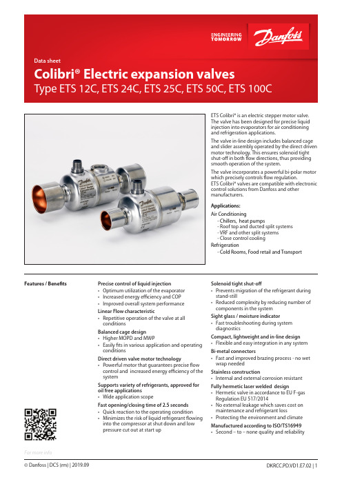
For more infoFeatures / BenefitsETS Colibri® is an electric stepper motor valve. The valve has been designed for precise liquid injection into evaporators for air conditioning and refrigeration applications.The valve in-line design includes balanced cage and slider assembly operated by the direct driven motor technology. This ensures solenoid tight shut-off in both flow directions, thus providing smooth operation of the system.The valve incorporates a powerful bi-polar motor which precisely controls flow regulation.ETS Colibri® valves are compatible with electronic control solutions from Danfoss and other manufacturers.Applications:Air Conditioning- Chillers, heat pumps - Roof top and ducted split systems - VRF and other split systems - Close control cooling Refrigeration- Cold Rooms, Food retail and TransportPrecise control of liquid injection• Optimum utilization of the evaporator • Increased energy efficiency and COP • Improved overall system performance Linear Flow characteristic• Repetitive operation of the valve at all conditionsBalanced cage design • Higher MOPD and MWP• Easily fits in various application and operating conditionsDirect driven valve motor technology• Powerful motor that guarantees precise flow control and increased energy efficiency of the systemSupports variety of refrigerants, approved for oil free applications• Wide application scopeFast opening/closing time of 2.5 seconds • Quick reaction to the operating condition• Minimizes the risk of liquid refrigerant flowing into the compressor at shut down and low pressure cut out at start upSolenoid tight shut-off• Prevents migration of the refrigerant during stand-still• Reduced complexity by reducing number of components in the system Sight glass / moisture indicator• Fast troubleshooting during system diagnosticsCompact, lightweight and in-line design • Flexible and easy integration in any system Bi-metal connectors• Fast and improved brazing process - no wet wrap neededStainless construction• Internal and external corrosion resistant Fully hermetic laser welded design• Hermetic valve in accordance to EU F-gas Regulation EU 517/2014• No external leakage which saves cost on maintenance and refrigerant loss• Protecting the environment and climate Manufactured according to ISO/TS16949• Second – to – none quality and reliabilityTechnical dataElectrical dataApprovals: ETS Colibri®CE, REACH, UL, (Fluid Group l and ll , article 4 para 3), LLC CDC EURO TYSK, EACApplied for: ATEX II 3G Ex nA T6ApplicationETS Colibri®CompressorEvaporatorDML/DCL Filter drierAKS temp. sensorsand press. transmitters089089Evaporating temperature t e : 5 °C / 40 °F Liquid temperature t l : 28 °C / 82 °F Condensing temperature t c : 32 °C / 90 °F Full stroke opening in normal flow directionCapacity is ± 10% in full open state in reverse flow directionOrderingCoolselector®2is a Danfoss calculation and selection software, designed to make selection processes for all refrigeration projects easier and less time consuming.For fast and precise selection of valve, use Danfoss’ CoolSelector2® software. You can download it from MADE IN DENMARK Colibri® Electric Expansion valve ETS XXXCN0317A10 Ω, 800mA peakPS 50bar / MWP 725psig -40/+70°C / -40/+158°F 034GXXXXMade in Denmark : Country of origin Colibri® Electric Expansion valve : Valve name ETS XXXC : Valve type N0317A (Manufacturing no.) : N = Nordborg, Denmark 03 = week 17 = 2017 A = Monday 10 Ω, 800 mA peak : Motor resistense, current PS 50 bar / MWP 725 psig : Max. working pressure -40/+70 °C / -40/+158 °F : Refrigerant temperature 034GXXXX : Code number : Approvals : QR code(with traceable serial no.)Danfoss, 6430 Nordborg,Denmark: Manufacturer addressIdentification(laser engraved data)Valid for ETS 25C, ETS 50C, ETS 100CDanfoss, 6430 Nordborg,DenmarkRoHSM12 angle female connector is intended for use with a standard M12 male connector, available onstepper motor valves.This cable is designed to offer high flexibility and small outer diameters with tensile strength.The angle way M12 cable consist of paired, twisted wires, which decreases mutual influence betweensignals transmitted along the cable and reduces influence of external sources of interference. Thecables thus provides a higher degree of protection against lost steps compared to other cables. Accessories:M12 angle cableApprovals for cableSpecificationIdentificationDimensionsConnectionsOrdering1252BAFlow direction from A to B refers the normal flow.Sightglass for flash gas detection can only be used in normal flow direction.Sight glass and indicatorETS 25C, ETS 50C and ETS 100C have integrated sight glass with moisture indicator. The presence of the sight glass provides the availability to check the physical position of the slider in the valve. It also helps to determine the flow direction of the refrigerant in the system. Insufficient sub cooling can produce flash gas which is visible through the sight glass. Themoisture indicator in the sight glass indicates dry Moisture indicator Green = dry Yellow = wet50% open75% open 3. Sight glass with moisture indicator 4. M12 electrical connection The colors of the grooves are only for illustration purposesDriving Colibri® valve with 3rd party controller ETS Colibri valves use a bipolar, 2-phase, permanent magnet stepper motor.ETS valves can be driven using various electronic control techniques i.e: Full step excitation mode, half step excitation mode, micro stepping mode (recommended).On selecting controller from other manufacturer than Danfoss, it is necessary to set the following correct valve data into the controller setting. The wrong settings may impair the performance of the valve.a. Total no. of steps - 600 full steps (or equivalent steps based on excitation mode, e.g 1 full step = 2half steps)b. Step rateFor current control driver:Step type: Microstep (1⁄4 th or higher): 240 full steps/sec. recommendedStep type: Full step or Half steps: 240 full steps/sec. recommended Emergency close : 240full steps/sec.c. Phase currentAlways use full current of 600 mA RMS (800mA Peak) for driving ETS Colibri when possible. For application that requires lower MOPD or moderate operating temperatures, it is possible to drive ETS Colibri with low driving current . See below guideline for details.d. Overdriving against closing position1% (i.e 6 full steps) Overdrive is recommended for optimum performance initialization during startup, 628 steps in closing direction recommended for initializationOverdriving in open position is not allowed.e. Holding currentNo permanent holding current needed. Max. 20% permanent holding current allowed with refrigerant flow through valveFor optimal performance, driver should keep 100% current on coils 10ms after last stepFor controllers with limited driving current, it will be good to have some holding current.- Condensing temperature t c : 32 °C / 90 °FFull stroke opening in normal flow direction. Capacity is ± 10% in full open state in reverse flow direction.* Operating conditions stated above are evaluated on refrigerants like R32/R410A for Chiller/Heat pump and R448A/R449A for Refrigeration.ETS Colibri guideline for using low current in 3rd party controllers, for low operating conditions.Electrical check of stepper motor and wiring:coil A and coil B = 10 Ω at 20 °C / 68 °FStepper motor switch sequenceAt power failure the ETS valve will remain in the actual opening position it has at the moment of power failure, unless a device in the form of a battery backup to the controller is installed.If the controller driving the ETS Colibri valve is from another manufacturer than Danfoss or a custom design, the following points must be considered in order to overcome potential step loss.To ensure total closing of the valve, and to compensate the lost steps after a defined number of changes in opening degree the controller should have a function to overdrive the valve in theclosing direction. It is recommended to overdrive the valve at appropriate intervals as specified in the specification table.1. It is always best to use the highest possible current achievable in the controller while going below standard phase current.2. Use lower speed rates to achieve higher torque while lowering the Phase current.3. Customer must evaluate the performance of the system while using ETS Colibri with lower phase current and with 3rd party controllers.4. All qualification testing of performance, robustness and reliability of Colibri has been conducted on 600mA RMS capable current drivers.Important notes:This section explains the operation of the two phase full step excitation method in a bipolar stepper motor. Fig. 1 shows the simplified diagram of a rotor and a stator. The Full stepping operation is summarized below.When a current in a form of a pulse flows to a given phase, that phase of the stator is excited as shown in Fig. 2.1. On exciting Phases B1 and A1 simultaneously, the permanent magnets on the rotor are moved in the intermediate position between phase B1 and phase A12. When phases A1 and B2 are excited simultaneously, the rotor is then positioned between phases A1 and B23. Next, by exciting the successive adjacent pairs of phases sequentially i.e phases B2 and A2, phases A2 and B1, and phases B1 and A1, the rotor rotates through two phase excitations4. By completely reversing the cycle in the following sequence phases B1 and A1 to phases A2 and B1 to phases B2 and A2 to phases A1 and B2, the stepper motor then reverses its rotation5. The stepper motor is stopped by holding the phase excitation for a specified period at the last phase of forward or reverse rotation Operation principleETS Colibri valves can also be driven by micro stepping excitation method (preferred) in addition to the one explained above.Two phase full step excitationDimensionsETS 12C / ETS 24CETS 25C, ETS 50C and ETS 100CRelated productsAKS 32R, AKS 32, AKS 33, NSKpressure transmitterAll Danfoss products fulfill the requirements in REACH.One of the obligations in REACH is to inform customers about presence of Candidate list substances if any, we hereby inform you about one substance on the candidate list: A moist indicator in the sight glass contains a paper which is impregnated with Cobalt Dichloride (CAS no: 7646-79-9) in a concentration above 0.1% w/w.Avoid skin contact with the paper - Do not inhale the dust from the paper - The paper must be disposed as hazardous waste.。
TOSHIBA Carrier 包装式空调的无线遥控器套件安装指南说明书

INSTALLATION MANUALTo Personnel Charged in Installation Work and ServiceWireless remote controller kitModel: RBC-AX33C-ULEB99806501(EN)•Thank you for purchasing Wireless remote controller kit TOSHIBA Carrier packagedair conditioner.•Read this manual carefully for correct installation of the wireless remote controller kitbefore starting work.•After the installation is completed, execute a test run to check for normal operationand explain how to use and maintain the wireless remote controller kit to the customeraccording to the Owner’s Manual.Ask the customer to keep this manual with the Owner’s Manual.Observe the safety precautions described in the Owner’s Manual of the wirelessremote controller kit, Installation Manual and Owner’s Manual of the ceiling type airconditioner (indoor unit).Accessory PartsSettings for the signal receiving unit before installationBefore installing the signal receiving unit, make the following settings referring to eachdescription.•To install the wireless remote controller together with wired remote controller,configure the “Multiple remote controller installation”•When ceiling height exceeds the standard height (factory default), refer to the"Installing indoor unit on high ceiling" on installation manual of the indoor unit.Install of the Signal Receiving Unit1.Remove a screw, move the sidepanel toward you (direction ofarrow), and then remove theside panel. (Fig. 1)p the end of flat head screwdriver with vinyl tape, andforcedly insert it into the grooveat the side under circle mark onthe cover. (Be careful not todamage the panel.) (Fig. 2)3.Pass the lead wire through thepanel, and install the signalreceiving unit to the panel hole.(Projection of the signalreceiving unit is fixed by thepanel hole.)4.Fix the lead wire of the signalreceiving unit to the cord clampwhich fixes the wires of thelouver motor. (Fig. 3)Flat head screw driverFig.3Note:Avoid to twist cables of the sensor with the power cables, otherwise a malfunction iscaused.*For cabling and TEST RUN, refer to “Wiring” of these sheets and “TEST RUN” of theInstallation manual attached to the indoor unit.Wiring<Wiring diagram>Multiple remote controller installationThe control by two remote controllers is enabled by installing the wireless remotecontroller with the wired remote controller for an indoor unit.(Max. 2 remote controllers of wireless or wired are insatiable.)“2-remote controllers” controlling means that one or multiple units are operated by themultiple remote controllers.Note:1.Upon confirmation of the terminal numbers of the indoor unit, connect the controlwire without miswiring. (If applied AC 208/230 V, damage the unit.)2.The multiple wireless remote controller kits cannot concurrently be used for anindoor unit.3.When installing simultaneously the wireless remote controller with the wired remotecontroller, set one of them as the follower remote controller.•To use wired remote controller or Lite-vision plus remote controller as a follower,settings must be changed. For the details, refer to the installation manual of eachcontroller.•To use the wireless remote controller as a follower, set bit 4 (Follower side) of DIPswitch SW30 on the signal receiving unit P.C. board to ON.2-remote controllersThe indoor unit is operated if either wireless or wired remote controller is set as headeror follower remote controller.(Total wire length: Within 1312ʹ4ʺ (400 m))5.Install the side panels, withscrews as original.6.Put the lead wire from the signalreceiving unit along wires of thelouver motor and others, andthen fix it with the cord clamp.(Fig. 4)*It’s connected to a connectionof Remote control wirethrough a hole for Remotecontrol wire.7.After all connections have beenmade, install the air intake grillbefore doing the “TEST RUN”.<Connection>Connect the wires out of the signalreceiving unit to the terminal blockfor remote controller wiring of theindoor unit. (They do not havepolarity.)Cord clampcontroller wiringFig.4Signal receivingunit P.C. boardGroup controlHeader and follower remote controllers are operable even if they are installed to anyindoor unit.(Total wire length: Within 656ʹ2ʺ (200 m))Remote controller address (A-B selection) setting•When two or more signal receiving units are installed in a room, a unique addresscan be set for each signal receiving unit to prevent interference.•Address (A-B selection) must be changed on both signal receiving unit and wirelessremote controller.•For the details of address change (A-B selection) on wireless remote controller, referto the owner's manual.Turn off the indoor unit power supply. Turn on the bit 4 of DIP switch SW30 on thesignal receiving unit P.C. board.The setting change is shown below.DIP switch [SW30]Test run (Forced cooling operation)Requirement:•Finish the forced cooling operation in a short time because it applies excessivestrength to the air conditioner.How to perform forced cooling operation1.When TEMPORARY button is pushed for 10 seconds or more, “Pi!” sound is heardand the operation changes to a forced cooling operation. After approx. 3 minutes, acooling operation starts forcedly.Check cool air starts blowing. If the operation does not start, check wiring again.2.To stop a test operation, push TEMPORARY button once again (Approx. 1 second).•Check wiring / piping of the indoor and outdoor units in forced cooling operation.4ON=follower OFF=header3ON=B OFF=A2Not used1Not usedWireless remotecontroller kit (Header)Wired remotecontroller (Follower)Control wire for group controlRemotecontrollerconnectionunitTEMPORARY buttonHow to handle the remote controllerIn case using remote controller mounting to the wall, etc.Self-diagnosis function and measures•The following table shows a few examples. For details of indoor unit errors, refer tothe Installation Manual of the indoor unit.LEDs on the signal receiving unit seconds)LEDNotes on installing remote controller•When using a wireless remote controller in the remote controller holder on a wall,turn on a fluorescent light and operate the remote controller at the installationposition. Make sure that the air conditioner operates normally and then secure theremote controller holder on the wall.•When installing a remote controller that senses room temperature with the sensor,avoid the following places.•A place exposed to direct cool air, warm air or direct sunlight•A place subject to thermal effectsExplanation to the customer•After the installation work has been completed, execute a test run to check for normaloperation and then hand the customer the Owner’s Manual and Installation Manual ofthe wireless remote controller kit.•Explain how to use and maintain the wireless remote controller kit to the customeraccording to the Owner’s Manual of the wireless remote controller kit.•Loading Batteries1.Remove the battery cover.2.Insert 2 new batteries (R03 [AAA]) following the (+)and (-) positions.ϕ0.16ʺ × 0.63。
2003年马歇罗德马歇罗德2003Marauder快速参考指南说明书

2003Marauder / quick reference guideFord Motor Company Customer Relationship Center 16800 Executive Plaza Drive P.O. Box 6248Dearborn, MI 481211-800-392-3673 (FORD)(TDD for the hearing impaired: 1-800-232-5952)All information contained in this Mercury Quick Reference Guide was accurate at the time of duplication. We reserve the right to change features, operation and/or functionality of any vehicle specification at any time. Your Mercury dealer is the best source for the most current information.For detailed operating and safety information,please consult your Owner’s Guide.Remote Entry System The remote entry system allows you to lock or unlock all vehicle doors without a key.Unlocking the Doors Press this control to unlock the driver’s door.The interior lamps will illuminate with the ignition OFF. Press the control a second time within three seconds to unlock all doors.Locking the DoorsPress this control to lock all doors. The horn will chirp and the parking lamps and tail lamps will flash to confirm the control was pressed.Opening the Trunk Press this control once to open the trunk. Sounding the Panic Alarm The panic feature operates with the key in the OFF position. Press this control to activate the alarm. To deactivate the alarm, press the control again, or turn the ignition to ACC or ON.Exterior Mirrors Po wer Side View MirrorsTo adjust these mirrors, select the left arrow to adjust the left mirror, the right arrow to adjust the right mirror. Move the control in the direction you’d like to adjust the mirror. Return to the center position to lock the mirrors in place. Heated Mirrors These mirrors warm up to remove ice, mist and fog when the rear window defrost is activated; attempting to remove ice from these mirrors by hand can damage the glass.Fold-Away Mirrors Pull the side mirrors in carefully when driving through a narrow space, like an automatic car wash.Aluminum Wheel Care Marauder’s polished, forged aluminum wheel rims are coated with a clear coat finish. To maintain their shine, clean them with Detail Wash, which is available from your Mercury dealer.Simply press AUTOMATIC and use the temperature controls toselect the temperature you prefer. This system will then heat or cool to achieve thattemperature, determining fan speed and airflow location.Press OFF to end Auto operation.Press the blue button for cooler air.Press OUTSIDE TEMP to displaythe outside temperature.How to Override Automatic OperationThe manual override controls will allow you to personally select airflow locations and fan speed. To return to automatic control, press AUTOMATIC.Choosing the MAX A/C manualoverride control will distribute recirculated air through the instrument panelregisters. MAX A/C is noisier than normal A/C, but more economical and efficient.Choosing the NORM A/C manualoverride control will distribute outside air through the instrument panel registers. It will only function if theoutside temperature is above 43degrees F. Normal A/C is more quiet than MAX A/C, but not as economical or efficient.Press the VENT manual overridecontrol to distribute the outside airthrough the instrument panel registers.Press the FLOOR manual overridecontrol to distribute air through thefloor ducts.Press the FLR•DEF (defrost)manual override control to distribute outside air through the windshield defroster ducts, the floor ducts and the side window demisters.Press DEF (defrost)to distribute air through the windshield defroster ductsand side window demisters. The A/C compressor willoperate automatically to clear ice and fog from the windshield.Fan speed will remain in automatic operation unless the fan speed thumbwheel is turned or the steering wheel fan speed control (if equipped)is pressed.Press the red button for warmer air.To return to automatic control, pressAUTOMATIC .See your Owner’s Guide for moreinformation on climate control.Power Windows Press the bottom portion of the switch to lower, the upper portion to raise. To use the express down feature, press the bottom portion and release quickly; the window will open fully.Depress again to stop window operation. The window lock feature allows only the driver to operate the power windows.Press the left side of the window lock to prevent passengersfrom lowering power windows; press the right side to restore use of the controls.Adjustable Pedals Your accelerator and brake pedals can be adjusted within 2.5”of original placement to provide you with an extra measure of driving confidence. Stop your vehicle, put the gearshift lever inP (Park) and press the rocker control to adjust the pedals toward you or away from you; adjust until you find the position that offers the greatest comfort and control.Hood Release The hood release handle is located below the instrument panel.Pull the handle toward you to release. From the front of your vehicle, release the auxiliary latch under the front center of the hood and lift until the lift cylinders hold it open. Trunk Release /Fuel Door Your trunk release is located on the trim panel of the driver’s door; press the control to open the trunk. To open your fueldoor, press the fuel door control (located directly behind the trunk release).Electronic Compass Located in the overhead console, this compass may be affected when you drive near large buildings, bridges, power lines and powerful broadcast antenna. To make compass adjustments,please see your Owner’s Guide.Power Seats The power seat controls are located in the trim panel of each front door. Press the top of the control to recline the seat back forward or backward. Slide the lower control to move the seat forward or backward. Press either end of the same control to move the seat cushion up or down. The lumbar controls are located on the inboard side of the front seat cushion.Essentials Automatic Temperature Control System April 2002First Printing Quick Reference Mercury MarauderLitho in U.S.A.3W3J-19G217-CA Location of the Spare Tire and Jack The full size spare tire is located in your trunk, in the area below the rear window.The jack can be found in a bag under or behind the spare tire. Fuses If electrical components in your vehicle are not working, a fuse may have blown.Blown fuses are identified by a broken wire within the fuse. To learn about changing fuses, please consult your Owner’s Guide.Fuel Pump Shut-Off Switch If you’re involved in a collision, your engine may crank but not start. That meansthe fuel shut-off switch may have been activated. You’ll find the switch on the left side of the trunk behind the left rear taillight and the trunk liner. For information on resetting, please see your Owner’s Guide.Unleaded Fuel Recommendations Use “Premium” unleaded gasoline with an (R+M)/2 octane rating of 91.Tire Pressure Adjust the tire pressure to the recommended specifications found on the certification label and inside the fuel door. When checking pressure, use an accurate tire pressure gauge. Check tire pressure when the tires are cold, after the vehicle has been parked for at least one hour or has been driven less than 3 miles. Warning:Improperly inflated tires can affect vehicle handling and can fail suddenly, possibly resulting in loss of vehicle control.Tire Rotation Since Marauder’s rear wheels are larger than the front wheels, rotations must be specific to each axle. In other words, the front wheels are interchangeable only with the front wheels and the rear tires are interchangeable only with the rear wheels.Roadside Assistance During your vehicle’s 3-year/36,000-mile limited warranty period, every new Mercury vehicle includes the assurance and support of a 24-hour emergency Roadside Assistance program. Roadside Assistance includes such services as fuel delivery, flat tire changes, jump starts, and help when you are locked out of your vehicle.Please complete your Roadside Assistance Identification Card and keep it in your wallet for quick reference. This card can be found in your glove compartment, in your Mercury Owner's Guide portfolio.Additional Features A B C D F G H I J KL B A E C L D F E G H I JK*F3W3J19G217CA*789101112Big, powerful and aggressive – the Mercury Marauder was designed for the individual who doesn’t follow the crowd. It was created for the enthusiast who demands the performance of an exhilarating all-aluminum 4.6L DOHC 32-valve V8, someone who knows how to handle 302 horses and 318 ft. lbs.of torque, someone who can appreciate the brushed aluminum instrument cluster and racing-style instrumentation, someone who refuses to sacrifice five-passenger luxury, comfort and convenience. Someone who wants it all.Congratulations on your choice. There’s a lot to learn about your new Marauder. Since we understand you’re anxious to enjoy your vehicle first-hand, we’ve provided you with this handy quick reference. It will briefly guide you through the basics of your vehicle’s most-used features.When you have more time, we ask that you see your Owner’s Guide for detailed information.“It was designed for someone like you.”Headlamp Controls Headlamps:The first position clockwise will illuminate the parking lamps; the second position will illuminate the headlamps.Autolamps: Turn the control counterclockwise to have the light-sensitive system automatically control your headlamps. DaytimeRunning Lamps:To turn your high beam headlamps on withreduced output, initiate high beams while key is in ON position, parking brake is released and the headlamp is in the OFF or parking lamps position. Foglamps:Pull the headlamp control toward you to turn them on. (Foglamps can be used with the headlamp control in the parking lamp, low beam or autolamp positions.) Dimmer:To adjust the brightness of your instrument panel, rotate the dimmer control to the left or right.Windshield Wiper/Washer Controls Rotate the windshield wiper control forward or backward to determine your desired interval, in low or high-speed position. The bars of varying length control your intermittent wipers. When in intermittent position, rotate the control forward for fast intervals,downward for slow intervals. Push the end of the stalk to activate the washer. For a longer wash cycle, push and hold.Turn Signal and High Beams Controls Push the stalk down to activate your left turn signal, up to activate the right turn signal. To use your high beams, push the turn signal stalk forward; pull toward you to deactivate.Speed Control To engage your speed control, make sure you’re traveling at or above 30 mph and press ON. To set a speed press SET ACCEL. To set a higher speed, press and hold SET ACCEL; release when you’ve reached the desired speed. To set a decreased speed, press and hold COAST; release when you’ve slowed to the desired speed. To return to a previously set speed, press RESUME (you must be traveling above 30 mph). To disengage,depress the brake pedal or press OFF .Check Engine Warning Light This light will inform you if there is a problem with your engine.It’s normal for the light to illuminate briefly when you start your engine. If the light stays on or blinks, there could be a problem. Have your vehicle serviced as soon as possible.Anti-Lock Brakes “ABS” provides enhanced security by detecting wheel lockup in hard braking situations. The light will illuminate momentarily when you start your engine; however if it fails to illuminate,stays on or continues to flash, see your dealership’s service department immediately.Clock Controls Your vehicle is equipped with a separate instrument panel mounted clock. Press H to set the hour, M to set the minutes.Steering Wheel Radio & Climate Controls Radio Control Features:Press VOL up or down to adjust the volume. Press BAND mode to select AM, FM1, FM2, TAPE or CD (if equipped). In radio mode, press MEM to select a preset station from memory. In tape or CD mode, press MEM to listen to the next selection or track. Climate Control Features:Press TEMP up or down to adjust the temperature, press FAN up or down to adjust fan speed.Rear Window Defroster Push to clear the rear window of thin ice and fog. The defrosterturns off automatically after 10 minutes, or when the ignition isturned off.Overdrive /Drive Overdrive:The normal driving position for the best fuel economy is Overdrive with this automatic transmission. It will increase your fuel economy when cruising at a constant speed for an extended period of time. Drive:On the other hand, Drive providesmore engine braking than Overdrive and is useful when driving with a heavy load, towing a trailer up or down steep hills, or any time you want additional engine braking. To activate Drive, press the control switch on the gearshift lever with the gearshift in the Drive position. Your transmission will operate in gears one through three. To return to Overdrive,press the transmission control switch. The O/D OFF indicator will no longer be illuminated.Voltmeter Gauge This gauge measures your vehicle’s battery charging voltage.If it consistently indicates less than 13.0 volts or more than 15.0 volts during normal operation, have your vehicle’s electricalsystem checked.Engine Oil Pressure Gauge This gauge indicates your Marauder’s oil pressure levels. If the indicator drops below the normal operating range or the minimum low pressure when your engine is running, shut off the engine andcheck the oil level. Add oil if necessary. Don’t operate your vehicle with the oil level below normal ranges (40-60 psi) or your engine may be severely damaged.178910111223456Audiophile SystemPremium AM/FM Stereo/Cassette/Single CD Audio System/Subwoofer with Internal Amplifier GKK A B C E D F HIJVolume / power control Press the control to turn the audio system on or off. Turn the control to raise or lower the volume.To choose Tape or CD With a tape already in place, chooseTAPE to begin tape play while in radio or CD mode. With a CD already in place,choose CD to begin CD play while in radio or tape mode. The first track of the CD will begin playing.Seek Function The SEEK function control works inradio, tape and CD modes. In radio mode,pressthe left arrow to find the nextlistenable station down the frequency band, the right arrow to find the next listenable station up the frequency band. In tape or CD mode, press the left arrow for the previous selection or track, the rightarrow for the next selection or track. AM/FM Selection The AM/FM select control works in radio, tape and CD modes. In radio mode,use this control to switch between AM,FM1 or FM2 memory preset stations. In tape or CD mode, use this control to stop and begin playing the radio.Tune AdjustTo move to the next frequency down the radio band, press the left arrow. To move through all the frequencies quickly, press and hold the leftarrow.Press the rightarrow to move up the band to the nextstation; hold the arrow to move quickly through the other stations.Bass + Treble Control Press BASS or TREB; press the leftarrow to decrease the level of BASS or TREB,the right arrow to increase the level.Scan FunctionThe SCAN function works in radio, tapeor CD modes. Press SCAN to hear a brief sampling of all listenable stations in radiomode, or to sample all selections in tape or CD modes. Press scan again to stop at thedesired selection.Balance + FadePress BAL and use the left arrow toshift thesound to the left speakers, theright arrow to shift sound to the right speakers. Press FADE and the right arrow to shift sound to the front speakers, the leftarrow to shift sound to the rear.Radio Station Memory PresetThese controls can be used to select upto six preset AM stations and twelve FMstations (six in FM1 and six in FM2).Choose the frequency band with the AM/FM select control; select a station –press and hold the memory preset control until the sound returns. Your selection will be held in the memory.Fast Forward + RewindTo fast-forward a CD or tape, press FF;to rewind, press REW.EjectPress EJ to stop and eject a tape or CD.For more detailed information on thefunctions of this audio system, please seeyour Owner’s Guide. B C D E FG H I JKA 123456。
- 1、下载文档前请自行甄别文档内容的完整性,平台不提供额外的编辑、内容补充、找答案等附加服务。
- 2、"仅部分预览"的文档,不可在线预览部分如存在完整性等问题,可反馈申请退款(可完整预览的文档不适用该条件!)。
- 3、如文档侵犯您的权益,请联系客服反馈,我们会尽快为您处理(人工客服工作时间:9:00-18:30)。
Multivariable control of indoor air temperature and humidity in a direct expansion (DX)air conditioning (A/C)systemQi Qi,Shiming Deng *Department of Building Services Engineering,The Hong Kong Polytechnic University,Kowloon,Hong Kong SAR,Chinaa r t i c l e i n f oArticle history:Received 26June 2008Received in revised form 10October 2008Accepted 4November 2008Keywords:Temperature and humidity Multivariable control Air conditioning system Direct expansiona b s t r a c tControlling indoor humidity at an appropriate level is very important since this affects occupants’thermal comfort and indoor air quality (IAQ).The paper presents an investigation on developing a multi-input multi-output (MIMO)control strategy for simultaneously controlling the indoor air temperature and humidity by varying the speeds of both compressor and supply fan in an experimental DX A/C system.The MIMO-based controller was designed based on the linearized dynamic model of the experimental DX A/C system.The Linear Quadratic Gaussian (LQG)technique was used in designing the MIMO-based controller.The controllability tests with respect to both the disturbance rejection capability and the command following capability were carried out to assess the control performance of MIMO controller.The results of disturbance rejection capability test showed that the MIMO control strategy can effectively maintain the indoor air temperature and humidity to their respective settings after an unmeasured heat load disturbance was imposed by simultaneously varying speeds of both the compressor and the supply fan of the DX A/C system.Furthermore,in the command following capability test for indoor air temperature,the test results showed that the indoor air temperature can be controlled to its new setting while indoor humidity remained unchanged.Similar test results were also observed in the command following capability test for indoor humidity.Therefore,the MIMO controller developed can effectively control indoor air temperature and humidity simultaneously by varying compressor speed and supply fan speed of the DX A/C pared to the previous related studies using conventional on–off control method or single-input single-output (SISO)control strategy,which can only effectively control either air temperature or relative humidity,the MIMO controller can simultaneously control the indoor air temperature and humidity with adequate control sensitivity and accuracy.The application of MIMO control strategy developed can be extended to other HVAC systems in the future to improve their operating performance and energy efficiency.Ó2008Elsevier Ltd.All rights reserved.1.IntroductionControlling indoor humidity at an appropriate level is very important since this directly affects occupants’thermal comfort and indoor air quality (IAQ)[1].Traditionally,reheating has been the principal method for indoor humidity control in central HVAC systems.This method is inherently costly and energy inefficient since it uses a great deal of energy to overcool the air,and then more energy to reheat the air to a suitable supply temperature.However,reheating is uncommon for DX A/C systems and controlling indoor humidity at an appropriate level using a DX A/C system is difficult.This is because the cooling coil in a DX A/C system must perform both cooling and dehumidification simulta-neously.Most DX A/C units are currently equipped with a single-speed compressor and supply fans,relying on on–off cycling compressor as a low-cost approach to maintain only indoor air dry-bulb temperature.This results in either space overcooling or an uncontrolled equilibrium indoor relative humidity (RH)level.The recent advancement of low-cost variable-speed drive (VSD)technology offers tremendous opportunities for improving indoor thermal control and energy efficiency for air conditioning.When the speed of a supply fan decreases,a lower airflow rate will decrease the sensible heat ratio (SHR)and improve the latent heat transfer in an air cooling and dehumidifying coil.This has been proved by the previous studies which demonstrated that lowering the airflow rate across an evaporator coil can improve moisture removal and thus enhance the control of indoor humidity [2,3].However,this would also impact on air temperature,so that the air exiting the coil will be not only drier but also cooler.On the other hand,for a DX A/C system when its compressor speed increases,its output cooling capacity will increase but its evaporating tempera-ture will decrease,hence its ability to remove moisture from air is*Corresponding author.Tel.:þ852********;fax:þ852********.E-mail address:besmd@.hk (S.Deng).Contents lists available at ScienceDirectBuilding and Environmentjournal homepage:/locate/buildenv0360-1323/$–see front matter Ó2008Elsevier Ltd.All rights reserved.doi:10.1016/j.buildenv.2008.11.001Building and Environment 44(2009)1659–1667improved.However,the changes in compressor speed would also affect the sensible heat transfer as its output cooling capacity changes.This will affect the indoor air temperature.Therefore,varying either supply fan speed or compressor speed would influ-ence both indoor air temperature and humidity although at difference magnitudes.Therefore it is possible to simultaneously control indoor air temperature and humidity by varying speeds of both compressor and supply fan for DX A/C system.Various control strategies have been developed for air condi-tioning systems.A fuzzy model-based predictive control scheme for controlling the supply air temperature was developed by Thompson and Dexter [4].Experimental results showed that the control performance of supply air temperature was satisfactory at both high and low airflow rates.Huang and Lam [5]developed an adaptive learning algorithm based on genetic algorithms (GA)for tuning proportional–integral–derivative (PID)controllers to achieve optimal control performance.Krakow et al.[6]proposed a PID control method to control indoor air temperature by varying compressor speed,and humidity by varying supply fan speed,respectively.Air conditioning systems have been traditionally controlled using simple single-input single-output techniques.Two control loops have been treated as two independent SISO systems [6],with their cross-coupling effects being often ignored.However,MIMO control strategies are able to take into account the coupling effects of multiple variables.They are more effective in simultaneously achieving multiple control objectives,such as:temperature,humidity,capacity,efficiency,etc.The performance of conventional SISO control strategies is inherently inferior to that of multi-input multi-output control strategies [7].He et al.[8]considered that there were strong cross-coupling effects among various operating parameters in a vapor compres-sion refrigeration cycle,such as evaporating temperature,condensing temperature,degree of superheat,etc.Therefore,in order to improve the transient behavior of the cycle in terms of maintaining a desired degree of superheat and evaporating temperature,an MIMO feedback controller was designed based on a low order lumped-parameter dynamic model [7].Controllability test results showed that the MIMO controller could effectively improve the operating performance and energy efficiency of the vapor compression refrigeration cycle.Rasmussen and Alleyne [9]presented the application of a multivariable adaptive control strategy to a general automotive air conditioning system.The possibility of coordinated modulations of both the expansion valve opening and the airflow rate passing through the evaporator as a control strategy was explored.It was demonstrated that the MIMO-based adaptive approach was very successful in achieving multiple objectives by regulating both degree of superheat and evaporating pressure.Furthermore,an MIMO controller for air temperature in,and ventilation to multiple zones in a building with a model predictive control (MPC)strategy was developed by Yuan and Perez [10].On the other hand,a direct digital control (DDC)-based control algorithm developed by Li and Deng [11,12]used space sensible heat ratio (SHR)as a controlled variable to simul-taneously control space air temperature and relative humidity.However,the control algorithm was not MIMO based.The experimental investigation by Krakow et al.[6]suggested that indoor air temperature and relative humidity may be controlled by separately varying compressor speed and supply fan speed.However,such a control strategy remained fundamentally inadequate.The transient performance of the two decoupled feedback loops (i.e.,the control loop for temperature by varying compressor speed and that for RH by varying supply fan speed)was inherently poor,due to the strong cross-coupling between the two feedback loops.Both air temperature and relative humidity were affected by compressor speed and supply fan speed.It can therefore be seen that artificially decoupling the control of two strongly coupled indoor air parameters,i.e.,air temperature and RH,would only yield poor control performance.Therefore an MIMO control strategy has been developed and is reported in this paper.The strategy considered the coupling effect of indoor air temperature and humidity for simultaneously controlling indoor air temperature and humidity by varying compressor speed and supply fan speed.It helped eliminate the artificial decoupling of the two coupled control variables,so that the control accuracy and sensitivity were improved.The organization of the paper is as follows.Section 2describes briefly an experimental DX A/C system and its dynamic model.The design of the MIMO controller based on the dynamic model afteritsQ.Qi,S.Deng /Building and Environment 44(2009)1659–16671660linearization is presented in Section3.The results of controllabilitytests of the MIMO controller are reported in Section4,and discussions presented in Section5.2.The experimental DX A/C system and its dynamic modelThe experimental DX A/C system was mainly composed of two parts,i.e.,a DX refrigeration plant(refrigerant side)and an air-distribution sub-system(air side).Its simplified schematic diagram is shown in Fig.1.The major components in the DX refrigeration plant included a variable-speed rotor compressor,an electronic expansion valve(EEV),a high-efficiency tube-louver-finned DX evaporator and an air-cooled tube-plate-finned condenser.The evaporator was placed inside the supply air duct on the air side to work as a DX air cooling coil.The nominal output cooling capacity from the DX refrigeration plant was9.9kW,operating with an evaporating temperature of7.2 C,a condensing temperature of 54.4 C,an ambient temperature of35 C and the wind speed of 2m sÀ1.The workingfluid of the plant was refrigerant R22,with a total charge of5.3kg.The air side included an air-distribution ductwork,a variable-speed centrifugal supply fan,and a conditioned space.The space was measured at 6.8m(L)Â3.9m(W)Â2.9m(H).Inside the space,there were sensible heat and moisture load generating units (LGUs),simulating the cooling load in the space.The experimental DX A/C system was fully instrumented for measuring and moni-toring all system operating parameters including temperatures and flow rates of both air and refrigerant,and pressures.The dynamic mathematical model for the DX A/C system was mainly derived from the energy and mass conservation principles. The following assumptions were made in developing the mathe-matical model:(1)perfect air mixing inside all heat exchangers and the thermal space,and no fresh air intake to the system;(2)two regions on the air side of the DX evaporator,i.e.,dry-cooling region and wet-cooling region;(3)negligible thermal losses in air ducts.In the DX A/C system to be modeled,the temperature and moisture content of the air leaving the DX cooling coil,as shown in Fig.1,were T1and W1,respectively.With the air perfect mixing assumption,air temperature,T2,and air moisture content,W2, leaving the conditioned space can be regarded as being equal to those in the conditioned thermal space.Based on the energy conservation principle,the sensible energy balance equation for the conditioned space was C p r V d T2¼C p r fðT1ÀT2ÞþQ loadþQ spl(1) where V was the volume of the conditioned space,Q load the space sensible load,Q spl heat gain of the supply fan,f is the air volumetric flow rate.The relationship between the air volumetricflow rate and supply fan speed S fan is as follows:f¼k fan S fan(2) The heat gain of supply fan increased with the airflow rate as follows:Q spl¼k spl f(3) On the other hand,the moisture mass balance inside the conditioned space wasr V d W2d t¼r fðW1ÀW2ÞþM(4)At the air side of the evaporator,with the assumption of no fresh air, the temperature and moisture content of the air entering evapo-rator were T2and W2,respectively.The air temperature decreased along the evaporator wall and was equal to T3at the end of dry-cooling region.Applying the energy balance principle in the dry-cooling region on the air side yielded:C p r V h1d T3d t¼C p r fðT2ÀT3Þþa1A1T wÀT2þT32(5)On the other hand,the coupled air cooling and dehumidification mainly took place in the wet-cooling region.Therefore the energy balance in the wet-cooling region can be written in enthalpy form:r V h2d h1¼r fðh3Àh1Þþa2A2T wÀT3þT1(6)The relationship between air enthalpy,temperature and mois-ture content wash¼C p Tþh fg W(7) where h fg was the latent heat of vaporization of water.Substitute Eq.(7)into Eq.(6)to obtain:C p r V h2d T1d tþr V h2h fg d W1d t¼C p r fðT3ÀT1Þþr fh fgðW2ÀW1Þþa2A2T wÀT3þT1(8)On the other hand,the refrigerant massflow rate can be determined by[13]:M ref¼sV comv s1À0:015hðP c=P eÞ1=bÀ1i(9)where s was the compressor speed and v s was the specific volume of superheated refrigerant,which can be obtained from measured pressure and temperature of refrigerant at compressor suction using the R22State Equations[14].Therefore the energy balance equation for the evaporator wall can be written asÀC p r VÁwd T wd t¼a1A1T2þT32ÀT wþa2A2T3þT12ÀT wÀM refðh r2Àh r1Þ(10)Variable speedcompressorCondenserFig.1.Simplified schematic diagram of the experimental DX A/C system.Q.Qi,S.Deng/Building and Environment44(2009)1659–16671661The supply air leaving the DX evaporator was assumed to be at 95%saturated.The relationship between air moisture content and temperature can be derived by plotting and curving fitting:d W 1d t Àð2Â0:0198T 1þ0:085Þd T1d t ¼0(11)Eqs.(1),(4),(5),(8),(10)and (11)formed the dynamic model of the experimental DX A/C system,which can be written as follows:The dynamic mathematical model of DX A/C system was linearized and written in state-space representation which was suitable for designing multivariable control,as follows:&_x¼Ax þBu y ¼Cx(13)where the state variables x ¼½d T 1;d T 2;d T 3;d T w ;d W 1;d W 2 T ,input variables u ¼½d f ;d s T ,and the output variables y ¼½d T 2;d W 2 T ,which were the dynamic deviations from their set points,respec-tively.A ,B and C were the coefficient matrices.The above dynamic mathematical model for the experimental DX A/C system has been experimentally validated and was reported elsewhere in detail [15].3.Design of the MIMO controllerThe MIMO-based controller was designed based on the linear-ized dynamic model of the experimental DX A/C system,i.e.,Eq.(13).A schematic diagram of the MIMO control system is shown in Fig.2.The main difference between an MIMO control system and an SISO control system was that the decoupled SISO control system only used one feedback signal to generate a single control input to a controlled object.For example,indoor air temperature was used to generate a signal to control compressor speed.However,the MIMO control system used two feedback signals,i.e.,indoor air temperature and moisture content,to generate two signals to control both compressor speed and supply fan speed simultaneously.Fig.3shows the block diagram of MIMO feedback control system.The MIMO controller was designed based on the technique of Linear Quadratic Gaussian (LQG)[16].An LQG multivariable controller was an observer-based compensator that used the Kal-man filter to optimally estimate unmeasured state variables basedon measured controlled variables,and then used the optimal full state feedback to generate a control law.The optimal gain matrix,K 1,and Kalman filter gain matrix,L ,were determined based on the system matrices in the dynamic model of the DX A/C system and the weighting matrices for linear quadratic regulator and weighting matrices for linear quadratic estimator.r was the reference set points of indoor air temperature and moisture content,and y the actual air temperature and moisture content inside the conditioned space.The optimal gain matrix,K 1,was calculated such that the feed-back control law,u ¼ÀK 1x ,minimized the cost function which compromised output errors and control efforts:J ¼Zðy 0Qy þu 0Ru Þd t(14)where Q and R are the weighting matrices.To obtain Kalman filter gain matrix,L ,the linear quadratic estimator design was considered.For the system with process noise and measurement noise [13]:&_x¼Ax þBu þw y ¼Cx þv(15)where w was process noise and v measurement noise,its optimal observer was given by_b x ¼A b x þBu þL y ÀC b x(16)where b x was an estimate of the state variables x .The observer gain was computed fromL ¼XC 0R À1(17)wherePwas the solution of an Algebraic Riccati Equation [13]:AXþXA 0þQ 0ÀXC 0R À10CX¼0(18)The weighting matrices Q 0and R 0can be suitably selected to obtainthe desire performance of the system.In this paper,Q 0¼1001!and R 0¼ 11!After the gain matrices K 1and L were obtained,the transfer function of the observer-based compensator LQG can be expressed asK ðs Þ¼K 1ðsI ÀA þBK 1þLC ÞÀ1L(19)In order to track the reference,an integrator should be included in the controller.The integrator variable was written as follows:_h¼r Ày (20)Therefore,the augmented state equationsbecomeFig.2.The schematic diagram of the MIMO control system.Q.Qi,S.Deng /Building and Environment 44(2009)1659–16671662_x a¼_x_h !¼A0ÀC0!xh!þB00I!ur!¼A a x aþB a u a(21)y¼½C0 xh!¼C a x a;x h!¼x a(22)The gain matrix,K2,can be selected to obtain the desire performance of the controlled system.In this paper,K2¼À0:0068750:00165À0:000405À0:000162!After obtaining the gain matrix K2,the control law can be expressed as follows:u¼ÀK1b xÀK2h¼À½K1K2 b xh!¼ÀK a x a(23)The transfer function of the LQG with integrators compensator can be expressed asKðsÞ¼K aðsIÀAþBK aþLCÞÀ1L(24) 4.Controllability test resultsThe MIMO controller was implemented in the experimental DX A/ C system.With the computerized instrumentation,all the measured data can be recorded for subsequent analysis,and the control inputs to the DX A/C system can be generated based on the feedback signals of measured indoor air temperature and moisture content.For the MIMO controller,its control performances were evalu-ated based on the following criteria:(1)Disturbance rejection:the output variables,i.e.,indoor airtemperature and moisture were to be maintained at their respective set points through simultaneously varying compressor speed and supply fan speed when the space was subjected to disturbances of space sensible and latent heat load changes.(2)Command following:the output variables can track changes oftheir set points with stability.When the set point of air temperature or moisture content was changed,the MIMO controller could react so that indoor air temperature or moisture content can be maintained at their respective new set point.For all controllability tests,indoor humidity control was via controlling indoor air wet-bulb temperature.Air moisture content can be evaluated by the properties of moist air after knowing air dry-bulb and wet-bulb temperatures.The MIMO controller was designed around an operating point of an indoor air dry-bulb temperature of24 C and a wet-bulb temperature of17 C(or an equivalent of air moisture content of9.34g/(kg dry air)or indoor relative humidity of50%).The compressor speed and supply fan speed were all initially set at3955rpm and2180rpm,both being 50%of their maximum speeds,respectively.The condenser cooling airflow rate was maintained constant at3100m3/h,with its inlet temperaturefixed at35 C.The refrigerant degree of superheat was maintained constant at6 C by using the EEV.In order to protect the compressor and supply fan and to avoid the speeds from changing sharply,each step change of both compressor speed and supply fan speed was set at not more than5%of their respective maximum speeds.The time interval between step changes was30s in all tests.4.1.Disturbance rejection capability testFor the test,indoor air settings were24 C(dry-bulb tempera-ture)and17 C(wet-bulb temperature)(or an equivalent of indoor air moisture content9.34g/kg dry air).These settings were expected to be maintained after the disturbances of both sensible load and latent heat loads were introduced.The MIMO controller would be enabled when either the deviation between the measured indoor air dry-bulb temperature and its setting or the deviation between the measured indoor air wet-bulb temperature and its setting was greater thanÆ0.5 C as a result of the disturbances.Figs.4and5present the controllability test results of distur-bance rejection capability of the MIMO controller.The variation profile of heat loads imposed over the entire test period is shown in Fig.4a.At t¼350s,the disturbances were introduced,with the sensible and latent heat loads increased from5.0kW to5.6kW,and from2.0kW to2.3kW,respectively.Fig.4b shows the variation profile of indoor air temperatures.During thefirst350s of the test, indoor air temperatures were maintained at their respective set points,i.e.,24 C dry-bulb and17 C wet-bulb before the distur-bances were introduced.Afterward,both air dry-bulb and wet-bulb temperatures increased gradually.At t¼1360s when indoor air dry-bulb temperature went over24.5 C,the MIMO controller was enabled.Fig.4c shows the variation profiles of compressor speed and supply fan speed.Following the action of the MIMO controller, both speeds increased.Towards the end of the test,the speeds of compressor and supply fan stabilized at around4750rpm and 2380rpm,respectively.The variation profiles of indoor air moisture content and relative humidity are presented in Fig.5a and b, respectively.As seen from Fig.4b,the MIMO controller can well control the indoor air dry-and wet-bulb temperatures to their respective set points,achieving a satisfactory performance in termsIntegratorFig.3.Block diagram of MIMO feedback control system.Q.Qi,S.Deng/Building and Environment44(2009)1659–16671663of disturbance rejection capability.At the end of test,the deviation between indoor air dry-bulb temperature and its setting was less than 0.1 C.mand following capability testsFor the command following capability tests,it was expected that when there were changes in set points,the MIMO controller would react so that the new settings can be tracked and maintained.Fig.6shows the controllability test results of the MIMO controller with respect to its command following capability,following a change in the set point of indoor air dry-bulb temper-ature.When the set point was lowered from 24 C to 23.5 C,with the setting of indoor air moisture content remaining unchanged at 9.34g/(kg dry air),the set point of the indoor air wet-bulb temperature had to be changed correspondingly from 17 C to 16.8 C.During the first 520s of the test,the DX A/C system was stable,and both indoor air temperature and moisture content were20003000400050006000S p e e d (r p m )Time (s)161820222426T e m p e r a t u r e (0C )1234567T h e r m a l l o a d s (k W )Fig.4.The variation profiles of some measured operating parameters in disturbance rejection capability test.05001000150020002500300035004000464748495051525354bR e l a t i v e h u m i d i t y (%)Time (s)8.08.59.09.510.010.511.0aM o i s t u r e c o n t e n t (g /k g d r y a i r )Fig.5.The variation profiles of measured moisture content and RH in disturbance rejection capability test.Q.Qi,S.Deng /Building and Environment 44(2009)1659–16671664maintained at their respective set points.At t ¼500s,the change of indoor air temperature setting from 24 C to 23.5 C was intro-duced,then MIMO controller was immediately enabled,as shown in Fig.6b.From Fig.6a,it can be seen that the MIMO controller can well control the indoor air dry-bulb temperature and wet-bulb temperature to their respective set points.From Fig.6c,it can be observed that indoor air moisture content can be maintained at its set point after the set point of indoor air temperature was altered.Fig.7illustrates the controllability test results of the MIMO controller,also with respect to its command following capability,following a change in indoor air moisture content setting which was achieved via a change in indoor air wet-bulb temperature.The set point of wet-bulb temperature was changed from 17 C to 16.6 C,or equivalently moisture content setting from 9.34g/(kg dry air)to 8.86g/(kg dry air),while the indoor air dry-bulb temperature setting was maintained at 24 C.The variation profiles of both indoor air dry-bulb and wet-bulb temperatures are shown in Fig.7a,and that of moisture content in Fig.7c.As seen from these figures,after the set point was changed,the MIMO controller responded by simultaneously varying speeds of both compressor and supply fan (Fig.7b),so that required new set point was approached in less than 1200s,and well maintained afterward.Therefore,the test results shown in Figs.6and 7suggested that the performance of the MIMO controller in terms of its command following capability was also satisfactory.5.DiscussionsSimultaneous control of indoor air temperature and humidity in a space served by a DX A/C system would require simultaneously varying the speeds of both supply fan and compressor of the DX A/C system.However,the changes in supply fan speed and compressor speed would have different levels of influence on indoor air temperature and humidity.When space sensible and latent heat loads were increased,the control of air dry-bulb temperature required the speeds of both supply fan and compressor to increase.However,the control of humidity required the speed of supply fan to decrease,but meanwhile required compressor speed to increase to output more cooling capacity for more moisture removal.Thus speed control would be in conflict if the coupling effect was not considered,and the result of control performance would be inherently poor.These can only be resolved by applying multivar-iable control strategy.From Fig.4,showing the results of disturbance rejection capa-bility test,when the MIMO controller was enabled,both supply fan speed and compressor speed were collaboratively increased to remove more sensible heat load because of a greater output cooling capacity from the DX cooling coil.Afterward,the speed of supply fan was decreased for removing more moisture from return air.Finally the indoor air temperature and humidity stabilized at around their respective settings.On the other hand,in Fig.6showing the results of command following controllability test after a change of indoor air temperature setting,it can be seen that indoor air moisture content rose above its set point before decreasing under the set point (Fig.6c).This was because the speed of supply fan was initially increased causing the sensible heat ratio of the DX cooling coil to decrease and consequently less moisture was removed even under an increased compressor speed.This also suggested that varying supply fan speed would influence SHR more than varying compressor speed,which agreed well with the results in previous related studies [2,3].Furthermore,similar phenomena may also be observed in Fig.7.8.08.59.09.510.010.5M o i s t u r e c o n t e n t (g /k g d r y a i r )Time (s)100020003000400050006000S p e e d (r p m )161820222426T e m p e r a t u r e (0C )Fig.6.The variation profiles of measured operating parameters in command following test with a change of air temperature setting.Q.Qi,S.Deng /Building and Environment 44(2009)1659–16671665。