齿轮油泵介绍
齿轮油泵结构特征

齿轮油泵结构特征概述齿轮油泵是一种常见的润滑设备,用于传输润滑油到润滑点,保证机械设备的正常运转。
本文将从齿轮油泵的结构特征方面进行深入探讨。
一级标题齿轮泵的基本结构齿轮油泵的基本结构主要包括齿轮、泵体、轴承、密封装置和进出口连接口。
其中,齿轮是齿轮泵的核心部件,负责传动润滑油。
泵体则起到固定齿轮和轴承的作用。
齿轮泵的工作原理齿轮油泵的工作原理是通过齿轮的旋转实现润滑油的吸入和排出。
当齿轮旋转时,齿轮之间的间隙会形成负压区域,润滑油会被吸入齿轮之间的空隙中。
随着齿轮的旋转,润滑油被推出泵体,流向润滑点。
二级标题齿轮泵的结构特征一:齿轮的形状齿轮的形状对齿轮油泵的性能有着重要影响。
常见的齿轮形状包括直齿轮、斜齿轮和螺旋齿轮。
直齿轮结构简单,传动效率高;斜齿轮可以减小齿轮噪声和振动;螺旋齿轮则能够增大润滑油的吸入能力。
齿轮泵的结构特征二:泵体的材料泵体的材料应具有良好的耐腐蚀性和刚性,常见的材料有铸铁、铸钢和不锈钢等。
铸铁具有较好的刚性和耐腐蚀性,但重量较大;铸钢则具有较高的强度和耐磨性,适合用于高压情况下;不锈钢具有良好的耐腐蚀性,适合用于特殊环境。
三级标题齿轮泵的结构特征三:轴承的类型轴承是齿轮油泵中重要的支撑部件,主要负责承受齿轮的轴向力和径向力。
常见的轴承类型有滚珠轴承和滚子轴承。
滚珠轴承由于其良好的刚性和高旋转精度,适用于高速运转的场景;而滚子轴承则具有较大的承载能力,适合承受较大径向力。
齿轮泵的结构特征四:密封装置的种类齿轮油泵的密封装置主要用于防止润滑油泄漏,保证系统的工作稳定。
常见的密封装置包括机械密封和填料密封。
机械密封通过密封环与泵体端面配合形成密封区域,具有较好的密封性能;而填料密封则通过填充一定的填料材料使泵体与轴构成密封。
总结齿轮油泵的结构特征包括齿轮的形状、泵体的材料、轴承的类型和密封装置的种类。
这些结构特征对于齿轮油泵的工作性能和使用效果起着重要的作用。
在选择和使用齿轮油泵时,需要根据实际需求选择适合的结构特征,以确保齿轮油泵的正常运行和润滑效果。
齿轮油泵动力参数计算公式

齿轮油泵动力参数计算公式齿轮油泵是一种常用的润滑系统设备,用于输送润滑油或润滑脂到机械设备的摩擦部位,以减少摩擦损耗,延长设备寿命。
在齿轮油泵的设计和选择过程中,需要对其动力参数进行计算,以确保其能够满足实际工作条件下的需求。
本文将介绍齿轮油泵动力参数的计算公式及其应用。
齿轮油泵的动力参数包括功率、扭矩和转速。
在实际工程中,通常需要根据所需的润滑油流量和工作压力来计算齿轮油泵的功率,然后根据功率和转速来计算所需的电机功率,最后根据电机功率和传动效率来计算所需的电机扭矩。
下面将分别介绍这些参数的计算公式及其应用。
1. 齿轮油泵功率的计算公式为:P = Q × p / η。
其中,P为功率(kW),Q为润滑油流量(L/min),p为工作压力(MPa),η为泵的效率。
根据这个公式,可以计算出所需的齿轮油泵功率,以满足实际工作条件下的润滑油流量和工作压力要求。
2. 根据所需的齿轮油泵功率和转速,可以计算所需的电机功率,其计算公式为:Pm = P / ηm。
其中,Pm为电机功率(kW),ηm为传动效率。
根据这个公式,可以计算出所需的电机功率,以满足齿轮油泵的功率和转速要求。
3. 最后,根据所需的电机功率和传动效率,可以计算所需的电机扭矩,其计算公式为:Tm = 9550 × Pm / n。
其中,Tm为电机扭矩(N·m),Pm为电机功率(kW),n为电机转速(rpm)。
根据这个公式,可以计算出所需的电机扭矩,以满足齿轮油泵的功率和转速要求。
以上就是齿轮油泵动力参数的计算公式及其应用。
在实际工程中,根据这些公式可以快速准确地计算出齿轮油泵的动力参数,以指导齿轮油泵的选择和设计工作。
同时,还可以根据实际工作条件的变化,调整这些参数,以满足不同工作条件下的需求。
希望本文对齿轮油泵的设计和选择工作有所帮助。
solidworks齿轮油泵课程设计

solidworks齿轮油泵课程设计摘要:一、齿轮油泵概述1.齿轮油泵的工作原理2.齿轮油泵的分类及应用领域二、SolidWorks 齿轮油泵课程设计1.SolidWorks 软件介绍2.使用SolidWorks 进行齿轮油泵设计的步骤3.齿轮油泵主要零部件的设计与建模4.齿轮油泵的装配与仿真三、齿轮油泵设计中应注意的问题1.材料选择2.参数设定3.性能优化四、结论1.SolidWorks 在齿轮油泵设计中的应用价值2.齿轮油泵设计对于相关行业的重要性正文:一、齿轮油泵概述齿轮油泵是一种通过齿轮的旋转来吸取和排放液体的泵。
其工作原理是利用两个相互啮合的齿轮,在齿轮旋转的过程中,将液体从进口吸入,然后通过齿轮的啮合将液体排放到出口。
由于齿轮油泵具有结构简单、体积小、流量稳定等优点,因此广泛应用于各种工业领域。
齿轮油泵主要分为外啮合齿轮油泵和内啮合齿轮油泵两大类。
其中,外啮合齿轮油泵又可分为径向齿轮油泵和轴向齿轮油泵;内啮合齿轮油泵则可分为双齿轮油泵和多齿轮油泵。
不同类型的齿轮油泵在结构、性能和应用领域上有所差别,需要根据实际需求进行选择。
二、SolidWorks 齿轮油泵课程设计SolidWorks 是一款功能强大的三维计算机辅助设计软件,广泛应用于机械、电子、航空航天等领域。
在齿轮油泵课程设计中,使用SolidWorks 软件可以方便地进行零部件的建模、装配和仿真,提高设计效率和质量。
使用SolidWorks 进行齿轮油泵设计的步骤如下:1.创建新文档,设置工作环境。
2.根据设计要求,绘制齿轮油泵的草图,包括泵体、进出口法兰、齿轮、轴承等零部件。
3.利用SolidWorks 的建模功能,将草图转化为三维模型。
4.对各零部件进行参数设置,如材料、尺寸等。
5.进行齿轮油泵的装配,将各零部件组合在一起。
6.利用SolidWorks 的仿真功能,对齿轮油泵进行性能分析,如流量、压力、温度等。
7.根据仿真结果,对齿轮油泵进行优化设计。
齿轮油泵的工作原理

齿轮油泵的工作原理
齿轮油泵是一种常见的液压泵,其工作原理是通过齿轮的旋转来产生压力,将液体从低压区域输送到高压区域。
下面将详细介绍齿轮油泵的工作原理。
齿轮油泵由两个齿轮组成,一个是驱动齿轮,另一个是从动齿轮。
驱动齿轮通过电机或其他动力源的驱动,使其旋转。
从动齿轮则随着驱动齿轮的旋转而转动,两个齿轮之间形成一定的间隙,称为齿隙。
当驱动齿轮旋转时,从动齿轮也跟随旋转,齿隙逐渐减小,液体被吸入齿隙中。
随着齿轮继续旋转,齿隙逐渐变小,液体被压缩,形成一定的压力。
当齿隙最小时,液体被推送到出口,形成高压液体。
齿轮油泵的工作原理与齿轮的设计有关。
齿轮的齿形和齿数决定了齿轮油泵的流量和压力。
齿形越好,齿数越多,齿轮油泵的流量和压力就越大。
同时,齿轮的材料和加工精度也对齿轮油泵的性能有影响。
高质量的齿轮可以减少泄漏和磨损,提高齿轮油泵的效率和寿命。
齿轮油泵的应用范围广泛,常用于液压系统中的润滑、冷却和传动等方面。
在液压系统中,齿轮油泵通常与液压缸、液压马达和液压阀等组合使用,实现液压系统的各种功能。
总之,齿轮油泵是一种常见的液压泵,其工作原理是通过齿轮的旋转来产生压力,将液体从低压区域输送到高压区域。
齿轮油泵的性能取决于齿轮的设计和加工精度,应用范围广泛,常用于液压系统中的润滑、冷却和传动等方面。
齿轮油泵零件间的装配关系

齿轮油泵零件间的装配关系齿轮油泵是一种常见的润滑系统,用于输送齿轮箱中的润滑油。
它由多个零件组成,这些零件之间的装配关系至关重要,直接影响到齿轮油泵的工作性能和寿命。
齿轮油泵的主要零件包括齿轮、轴、泵体和密封件等。
这些零件之间的装配关系决定了齿轮油泵的工作效率和密封性能。
齿轮是齿轮油泵的核心部件,它通过齿轮传动的方式将润滑油从低压区域输送到高压区域。
齿轮之间的装配关系要保证齿轮的啮合精度和间隙,以确保润滑油的顺畅输送和泵的工作效率。
轴是连接齿轮和泵体的关键部件,它承受着齿轮的转动力和润滑油的压力。
轴与齿轮之间的装配关系要保证轴的刚性和精度,以避免轴变形和齿轮偏移,从而影响泵的工作性能。
泵体是齿轮油泵的外壳,它承载着齿轮和轴等零件,并与其他部件一起形成一个密闭的工作腔室。
泵体与其他零件之间的装配关系要保证泵体的刚性和密封性,以防止润滑油泄漏和泵体变形。
齿轮油泵还需要一些密封件来保证其密封性能。
这些密封件包括垫圈、密封圈和密封垫片等,它们与齿轮、轴和泵体之间形成密封界面,防止润滑油泄漏。
密封件与其他零件之间的装配关系要保证密封件的质量和尺寸精度,以确保齿轮油泵的密封性能。
在齿轮油泵的装配过程中,需要注意以下几个关键点:1. 零件的清洁:在装配过程中,需要保证每个零件的表面清洁,防止灰尘和杂质进入齿轮油泵内部,影响其工作性能。
2. 装配顺序:按照齿轮油泵的装配顺序,先装配齿轮和轴,再将其装配到泵体中。
最后安装密封件,确保装配的顺序和方法正确。
3. 装配力度:在装配过程中,需要控制装配力度,避免过紧或过松,以确保齿轮油泵的正常工作。
4. 润滑油的添加:在装配完成后,需要添加适量的润滑油,以保证齿轮油泵正常运转。
通过合理的装配关系,齿轮油泵的各个零件可以协同工作,实现润滑油的顺畅输送和泵的高效运转。
因此,装配关系在齿轮油泵的制造和维护中起着至关重要的作用。
齿轮油泵零件间的装配关系是保证齿轮油泵工作性能和寿命的关键因素。
齿轮油泵性能及参数
齿轮油泵性能及参数一、齿轮油泵产品概述:1、本泵适用于输送各种有润滑性的液体,温度不高于70℃,如需高温200℃,同本单位联系可配用耐高温材料即可,粘度为5×10⁻⁵~1.5×10⁻³m2/s。
2、齿轮油泵不适用于输送腐蚀性的、含硬质颗粒或纤维的、高度挥发或闪点低的液体,如汽油、笨等。
泵体中装有一对回转齿轮,依靠两齿轮的相互啮合,把泵内的整个工作腔分两个独立的部分。
泵运转时主动齿轮带动被动齿轮旋转,当齿轮脱开啮合时在吸入侧就形成局部真空,液体被吸入。
被吸入的液体充满齿轮的各个齿谷而带到排出侧,单级单吸油泵齿轮进入啮合时液体被挤出而排出泵外。
二、齿轮油泵结构说明:本产品由泵体、齿轮、前后泵盖、安全阀、轴承及密封装置等零、部件组成。
1、泵体、前后盖等零件为灰铸铁件,齿轮用优质碳素钢制作;亦可根据用户需要用铜材或不锈钢制作。
2、安全阀。
齿轮油泵自身不带安全阀,用户在使用时需自行在管路系统中安装安全阀。
KCB,系列齿轮油泵在后泵盖或泵体上方装有安全阀,当泵或排出管道发生故障或将排出阀门完全关闭而产生高压和高压击时安全阀就会自动打开,卸除部分或全部的高压液体回到吸入腔,从而对泵及管道起到安全保护作用。
3、轴承。
齿轮油泵全部采用DU轴承;可根据用户要求采用锡青铜轴承。
&0818.3-83.3、1.1齿轮油泵采用DU轴承;可根据用户要求采用锡青铜轴承。
KCB133-960、8-60齿轮油泵有采用DU轴承,锡青铜轴承和滚动轴承三种结构,需在订货时注明。
订货时未注明者均按DU轴承结构供货。
轴承为内置型式,依靠被输送介质进行润滑;011轴承和锡青铜轴承能在非润滑性介质中工作。
4、轴封。
本系列产品的轴端密封有骨架油封、机械密封及填料密封三种结构。
a.骨架油封:骨架油封的特点是维护、更换方便,成本低,但寿命较短。
丁晴胶骨架油封适用于1001:以下工作环境;氟橡胶骨架油封适用于200℃以下工作环境。
齿轮式机油泵的工作原理

齿轮式机油泵的工作原理齿轮式机油泵是一种常见的润滑系统元件,其主要作用是将机油从油底壳中吸取并压送到发动机内部各个润滑点,以保证发动机的正常运转。
下面将详细介绍齿轮式机油泵的工作原理。
一、齿轮式机油泵的结构齿轮式机油泵由驱动齿轮、从动齿轮、泵体和配流器等组成。
其中,驱动齿轮由发动机曲轴带动旋转,从而带动从动齿轮旋转,使得泵体内的机油被吸入,并通过配流器被压送至发动机润滑系统。
二、齿轮式机油泵的工作原理1. 吸入阶段当发动机启动时,曲轴带动驱动齿轮旋转,从而带动从动齿轮旋转。
在此过程中,因为两个相互啮合的齿轮之间存在空隙,所以在其啮合点附近形成了一定大小的容积。
当从动齿轮与驱动齿轮之间形成容积时,泵体内的机油就会被吸入到齿轮之间的空隙中。
2. 压送阶段当从动齿轮继续旋转时,其啮合点逐渐向泵体的出口方向移动,从而使得齿轮之间的容积逐渐减小。
因为机油是不可压缩的,所以在容积减小的过程中,机油会受到一定的压力作用,并通过配流器被压送至发动机润滑系统。
3. 排出阶段当从动齿轮完全旋转一周后,其啮合点回到了起始位置。
此时,在驱动齿轮和从动齿轮之间仍然存在一定大小的容积,但是其中已经没有机油了。
因此,在下一个工作周期开始前,需要将这部分空气排出泵体,以便下一次工作时能够正常吸入机油。
三、齿轮式机油泵的优缺点1. 优点(1)结构简单:由于齿轮式机油泵只由少量部件组成,因此其结构相对简单。
(2)工作稳定:由于其工作原理比较简单,在使用过程中很少出现故障。
(3)压力稳定:齿轮式机油泵在压送机油时,由于齿轮之间的容积是固定的,因此其压力相对稳定。
2. 缺点(1)噪音大:由于齿轮之间存在空隙,因此在工作过程中会产生一定的噪音。
(2)易磨损:由于齿轮之间需要相互啮合,因此在长期使用过程中容易磨损。
(3)润滑不足:由于齿轮式机油泵本身就是用来压送机油的,因此其自身润滑不足。
如果长时间使用不加润滑油,则会导致泵体内部的齿轮磨损加剧。
齿轮泵简介(中英对照)

Gear pumpChinese Name: gear pumpName: gear pumpDefinition: rely sealed in a housing of two or more gears, the work space is generated in the process of mutual engagement volume change to liquid delivery pump.Applied disciplines: mechanical engineering (a subject); drive (two subjects); hydraulic transmission (two subjects)The gear pump is to rely on the change and moving of the working volume of the pump cylinder and the ring gear formed between rotary pumps for conveying liquid or so pressurized. Form two closed space by two gears, pump, front and rear cover, when the gear is rotated, the gear is disengaged from the side of the space volume grew larger, forming a vacuum, the liquid suction, the gear meshing side of the volume of the space from large small, while the liquid squeeze into the pipeline to go. The suction chamber and the discharge chamber is spaced by two gears meshing line to. The outlet pressure of the gear pump is entirely dependent on the size of the pump source resistance.The concept of the working principle of the gear pump is very simple, i.e. in its most basic form is the same as the two dimensions of the gear in a close fit within the housing.The engagement rotation, the interior of the housing is similar to the "8" shape, the two gears are mounted on the inside, the outsidediameter of the gear, and both sides of the housing close fit. From the extruder, the material in the suction port into the middle of the two gears, and to fill this space, the rotation direction of the housing with the teeth movement, and finally discharged in the two toothing.Speaking in terminology, gear pump, also called a positive displacement device, i.e. as a cylinder bore of the piston, when one tooth into the fluid space of another tooth, the liquid is mechanically squeezed row out. Because the liquid is incompressible, so the liquid and the tooth at the same time can not occupy the same space, so that the liquid has been excluded. This phenomenon continuously occurs due to the continuous engagement of the teeth, and, therefore, at the outlet of the pump provides a continuous excluded volume pump per revolution, the same amount of discharged. With the uninterrupted rotation of the drive shaft, the pump also continuously discharged fluid. The pump flow is directly related to the speed of the pump.In fact, in a pump with a small amount of fluid loss, which makes the efficiency of the operation of the pump can not reach 100%, because these fluids are used to lubricate bearings and gears on both sides, and the pump body can never be a clearance fit, so can not make 100% offluid from the outlet, so asmall amount of fluid loss is inevitable. However, the pump or can run well, can still reach an efficiency of 93% to 98% for most of the extrudate,.Viscosity or density changes in the process fluid, the pump will not be much of an impact. If there is a damper, for example in theoutlet side accommodates a strainer or a limiter, the pumps will pushfluid through them. If the damper changes in their work, i.e., if the filters become dirty, clogged, or the back pressure of the limiter, the pump will continue to maintain a constant flow rate, until the device of the weakest parts of the mechanical limit is reached (usually equipped with a torque limiter).The rotational speed of a pump, in fact, is limited, which mainly depends on the process fluid, and if the transmission is oil, the pump can be rotated at high speed, but when the fluid is a high viscosity of the polymer melt body, this restriction will be substantially reduced.Promote the highly viscous fluid to enter the intake port side of the two tooth space is very important, if this space is not filled, then the pump would not discharge the flow of accurate, so the value of PV (pressure x velocity) is another limiting factor, and is a process variable. Because of these limitations, the gear pump manufacturer will provide a range of products of different specifications and displacement (for each revolution of the amount discharged). These pumps will be compatible with the specific application process to make the system optimal capacity and price.PEP-II of the pump gear and shaft are of integrally quintana hardened process, to obtain a longer working life. "D" type bearing a combination of forced lubrication mechanism, so that the polymer via a bearing surface, and returns to the inlet side of the pump, in order to ensure effective lubrication of the rotation shaft. This feature reduces the possibility of retention and degradation of polymers. Precision machining of the pump shaft exact fit, to the bearings and gears of the "D" type can ensure that the gear shaft is not eccentric, to prevent thegear wear. The Parkool sealed structure with PTFE lip seal a water-cooled sealed together. Such seals do not actually touch the surface of the shaft, its sealing principle is that the polymer is cooled to asemi-molten state and form a self-sealing. May also be used Rheoseal sealing it in a reverse spiral groove seal sheet processing, the polymer can be anti pressed back imported. For ease of installation, the manufacturer to design an annular bolt mounting surface to enable the flange installation cooperating with other devices easier, which makes the manufacture of the cylindrical flange. PEP-II gear pump with heating element matches with the specifications of the pump, available to users matching, which can ensure the rapid heating and heat control. Different pump body heating mode, the damage to these components only a board, independent of the entire pump.The gear pump is driven by a separate motor, effectively blocking the upstream pressure pulsation and flow fluctuations. Gear pump outlet pressure pulsation can be controlled within 1%. In the extrusion production line using a gear pump, and can improve the speed of flow rate output, and to reduce theshearing of the material in the extruder and residesThe external gear pump is the most widely used as a gear pump, the general gear pump is usually refers to external gear pump. Its structure is shown in Figure 5-14, the main drive gear, driven gear, pump, pump cover and safety valve. The sealed space gear pump pump, pump cover and gear constitute studio. Two gear axle are fitted respectively in the two bearing bore of the pump cover, out of the pump body, the driving gear shaft driven by the motor rotation. External gear pump is simplestructure, light weight, low cost, reliable work, a wide range of applications.Gear pump working, driving wheel with the motor to rotate and drive the driven wheels to follow the rotation. When the suction chamber side of the meshing teeth gradually separate, the volume of the suction chamber is increased, the pressure is reduced, put the liquid suction pump suction human tube; suction liquid two routes in the alveolar gear pushed onto the discharge chamber. Liquid into the discharge chamber, since the two gear teeth continuously engaged, liquid is squeezed from the discharge chamber into the discharge pipe. Driving gears and driven gears are constantly rotating, the pump can be continuous suction and discharge liquid.Equipped with a safety valve, a pump, conveying the liquid may be automatically open the top valve, so that the high pressure liquid is returned to the suction pipe when the discharge pressure exceeds a predetermined pressure.The internal gear pump, the inner gear, by a pair of mutually meshing and the middle of the crescent-shaped member, the pump casing and the like. The crescent-shaped member is spaced from the suction chamber and a discharge chamber. When the pinion gear is rotated, a partial vacuum is formed, in the place of the gear is disengaged, the liquid being sucked A pump filled with the suction chamber interdental, and then along the inner and outer sides of the two routes of the crescent-shaped member into the discharge chamber. In place of the tooth into engagement, the liquid present in the interdental is extruded while the feed discharge tube.Gear pump with self-priming capability, flow and discharge pressure independent pump casing, suction valve A and the discharge valve has a simple structure, uniform flow, reliable, low efficiency, noise and vibration, easy wear, used to transport non-corrosive, non-solid particles and various oils with lubricating ability, the temperature is generally not more than 70 '° C, such as lubricating oil, edible oil. The general flow range of 0.045 ~ 30ms / h, pressure range of 0.7-20MPa, working speed 1200-4000r/min.Structural featuresGear ninety people advanced level of new technology - dual arc sine curve tooth arc. Involute gear, the most prominent advantages Tooth Surface gear meshing process there is no relative sliding tooth surface wear, and stable operation the trapped fluid phenomena, low noise, long life, high efficiency.The pump to get rid of the shackles of the traditional design into a new area in the design, production and use of the gear pump.The pump has a differential pressure relief valve as overload protection, safety valve total reflux pressure pump rated discharge pressure of 1.5 times. Allows discharge pressure range in accordance with the actual need to be adjusted separately. But this safety valvefor not reducing valve long-term work, the need to separately install the pipeline.The shaft end seal design for the two forms, a mechanical seal, a packing seal, can be determined according to the specific use conditions and user requirements.Operation and maintenance, start:Gear pumps(1) before the start of check all pipe flange joint tightness.(2) coupling plate moving without friction and collision sound.(3) The first time you start the pump should be injected into the transmission fluid.(4) before the start of fully open suction and discharge valve in the pipeline, the non-closing valve starts.(5) Verify that the motor rotation direction, start the motor.2, Parking:(1) Turn off the motor.(2) Turn off the pump inlet and outlet valves.Common faults can not discharge(1) failure phenomenon: the pump can not dischargeGear pump the whole picture (3) the cause of the malfunction: a rotating in opposite directions; b, suction or discharge valve closed; c, the entrance no material or pressure is too low; d, the viscosity is too high, the pump can not bite materialCountermeasures: a, confirm the direction of rotation; confirm valve is closed; c, check valves and pressure gauges; d, check theliquid viscosity, low speed according to the speed ratio of the flow, if flow is insufficient flowsInadequate flow(2) failure phenomenon: pump flow the lack KCB300 gear pumpThe cause of the malfunction: a, inhalation or discharge valve closed; b, low inlet pressure; c export pipeline blockage; d, stuffing box leakage; e, the speed is too lowCountermeasures: a confirmation whether the valve is closed; b, the check valve is open; c confirm excretion is normal; d, fastening; drain large leak affecting production, should stop operation, demolition inspection; e, check the pump shaft speed ;Abnormal sound(3) failure phenomenon: abnormal soundThe cause of the malfunction: a coupling the the eccentric big or poor lubrication b, motor failure; abnormal c reducer; to poor installation d seal at; e shaft deformation or wearCountermeasures: a look for positive or filling grease; b, check the motor; c, check the bearings and gears; d, check the seal; e, parking disintegration of inspectionCurrent is too large(4) failure phenomenon: the current to excessive gear pump seriesThe cause of the malfunction: a outlet pressure is too high; b, the melt viscosity is too large; poor c, shaft seal assembly; the d shaft or bearing wear; e, motor failureCountermeasures: a to check downstream equipment and piping; b testing viscosity; c, check the seal properly adjusted; d, parking after checking hand drive cars are overweight; e, check the motorPump suddenly stopped(5) failure phenomenon: the pump suddenly stoppedThe cause of the malfunction: a power outage; b, motor overload protection; c coupling damage; d, the outlet pressure is too high, the chain reaction; e pump, biting into the anomaly; f, shaft and bearing adhesive stuck Countermeasures: a, check the power;, check the motor; c, f turning to open the safety cover, turning checks; d check the instrumentation interlock system; e, after stopping, reversing turning confirmed; confirmSeal oil spill(6) failure phenomenon: sealing oil spillCause: a shaft seal is not adjusted, seal wear between fine c mechanical seal dynamic friction surface of the stationary ring with bad four spring relaxation Countermeasures: a re-adjustment of b, the rightamount tighten the gland bolts or replace the seals, c, replace the dynamic and static ring or reground, four replacement springOther phenomena1 causes(1) internal and external rotor backlash too the suction pressureoil chamber interoperability. Significantly reduce the volumetric efficiency, the output flow is not enough;②axial clearance is too large;③the suction line junction surface Mifengbuyan the other reasons, so that the pump into the air, effective suction flow reduction;④Suction poor. As a result of the oil viscosity is too large, the oil filter clogged by dirt as a result of the inhalation flow reduction;⑤relief valve stuck in the half-opening position, part of the pump to the flow back to the tank through the relief valve, and making the traffic into the system is not enough. At this time accompanied by a failure do not increase the system pressure.2, Remedy①replace the inner and outer rotor, the tooth side of the gapwithin a predetermined range (typically less than 0.07 mm);②both ends of the grinding pump surface, to ensure that after the assembly of the rotor inside and outside the axial gap in the range of0.02 ~ 0.05mm; (3) replacing defective suction pipe seal, bandaged pipe fittings threaded portion and then tighten fittings with Teflon tape;(4) appropriate viscosity oil, washing oil into the oil filter to make oil-absorbing smooth. And, where appropriate, to increase the oil absorption diameter;⑤repair relief valve, to exclude relief valve shorted fuel tank caused the pump effectively reduced flow phenomenon.Edit this paragraph the trapped oil phenomenon gear pump to a smooth work, the degree of coincidence of the gear must be greater than 1, so there are always two pairs of gears engaged simultaneously, and a part of the oil is siege surrounded by a closed cavity in the two pairs of teeth between. This closed cavity begins with the rotation of the gear is gradually reduced, and later gradually increased. Closed chamber volume decreases causes trapped fluid by squeezing generate high pressure, and is extruded from the gap, leading to fluid heating, and to enable the parts to subject to additional loads; while the increase in volume of closed chamber also caused a partial vacuum, and dissolved in the oil in the gas separation, the occurrence of the cavitation. These will generate a strong vibration and noise, which is a gear pump phenomenon of trapped oil.HarmThe radial imbalance force is large enables the shaft bending, the tooth tip in contact with the housing, while the accelerated wear of the bearings and reduce the life of the bearing.EliminationMethod to eliminate the trapped oil, usually in the both sides of the cover open unloading groove, so that the volume of the closed chamber is reduced through the left unloading groove communicates with the oil pressure chamber, the volume increases when the unloading tank with the suction chamber through the right side connected.Feasible circuit performance to improve the performance of gear pumpGear pumps due to the structural constraints of the fixed displacement gear pump is generally considered only for the constant flow hydraulic source. However, the accessories and threaded coupling combination valve program is effective for improving its functionality, reduce system cost and improve system reliability and, therefore, the performance of the gear pump approachability expensive, complex piston pump.Mounted directly on the pump control valve, eliminating the need for tubing between the pump and the directional valve, to thereby control the cost. Fewer fittings and connectors to reduce the leak, and to improve reliability. And the pump itself valve can reduce the loop the loop pressure to improve theperformance of their work. Here are some of the basic functions of the gear pump can improve the loop, some of which is proved to be feasible practice basic loop, and some of the innovative research.Uninstall loopUninstall components will combine high flow pump with low-power single-pump. The liquid from the two gear pump due to the structural constraints of the fixed displacement gear pumps usually considered only for the constant flow hydraulic source. However, attachments andthreaded coupling combination valve program to enhance its functionality, reduce system cost and improve system reliability to be effective, therefore, gear pumps, fixed displacement due to structural constraints, usually considered only for constant flow gear pump hydraulic source to use. However, the accessories and threaded coupling combination valve program is effective for improving its functionality, reduce system cost and improve system reliability and, therefore, the performance of the gear pump approachability expensive, complex piston pump. Performance accessible expensive, complex piston pump. The outlet, until it reaches a predetermined pressure, and (or) traffic. At this time, the large flow pump put flow from the outlet is recycled to the inlet, thereby reducing the output flow of the pump system, the upcoming pump power is reducedto just above the desired value of the high-pressure part of the work. The percentage depends on the flow rate decreases not uninstall displacement ratio of total displacement. Combination or threaded coupling unloading valve to reduce or eliminate the pipes, channels and accessories, and other possible leaks.Easiest unloading member by manual manipulation. Spring unloading valve is turned on or off, when a manipulation of the signal to the valve, the valve off state is switched. Leverage or other mechanical agencies is the easiest way to manipulate this valve.Guidance and control (pneumatic or hydraulic) unloading valve is an improvement of the mode of operation, because such valves can be remotely controlled. Its greatest progress is a solenoid valvecontrolled by an electrical or electronic switch, it is not only the available remote control available microcomputer automatic control, generally considered this simple unload technology is the application of the best case.The artificial manipulation uninstall components commonly used in large flows and fast action to be large flows and reduce the flow loop for precise control, such as rapid telescopic boom circuit need for fast action. Unloading valve of the circuit shown in Figure 1 without the manipulation of the signal effect, the large flow loop always output. For a normally open valve, in the normal state the loop will output a small flow.Pressure sensing unload valve is the most common solution. As shown in Figure 2, the spring action of the unloading valve is in its flow position. Circuit pressure relief valve preset value is reached, the relief valve to open, the uninstall switch valve in the hydraulic and under to its small flow position. Thepressure sensing uninstall circuit used for the trip to their fast, low speed high pressure fluid supply of the hydraulic cylinder when the end of the trip. Pressure sensing unloader valve base is basically a reach system pressure and unloading automatically uninstall components, generally used for the splitter mileometer and hydraulic vise.Unloader valve is the flow sensing uninstall loop pressure to the large flow position by a spring. The fixed orifice size of the valveflow to determine the optimum speed of the engine required. If theengine speed exceeds this optimum range, the throttle orifice pressure drop will increase, which will unload valve shift to small flow position. High flow pump adjacent elements made of the size of the maximum flow throttle, therefore circuit energy consumption less smooth and low cost. Typical applications of this loop, the loop defining flow rates up to an optimum range in order to improve overall system performance, orqualified machine during traveling at high speed loop pressure. Commonly used in the garbage carrying trucks.Pressure flow sensing the uninstall circuit of unloading valve is pressed to the large flow position by a spring, whether it reaches a predetermined pressure or flow, will uninstall. Idling or normal operating speed, the equipment can be used to complete the high-pressure job. This feature reduces the unnecessary traffic, and therefore reduces the required power. Because such a circuit having a wide range of load and speed changes, Guchang for excavation equipment.With power integrated pressure sensor the uninstall circuit, by two minor changes in the pressure sensing uninstall pump, two sets of pumps driven by the same prime mover, Guidance and control unload signal to accept another uninstall pump each pump. Such sensing mode called interactive sensing, it enables a set of pump to work under highpressure and the other set of pump work in a large flow. Two reliefvalve is adjusted according to each special loop pressure to make one or two pumps to uninstall. This program has reduced power requirements, and therefore inexpensive prime mover of the small capacity can be used.The load sensing Uninstall loop. When the load-sensing signal tothe main control valve control chamber (lower chamber), the pump flow rate through valve 1, a valve 2 rows back to the tank; when the load-sensing signal is applied to the control valve, the liquid supply pumpto the loop; When the pump output pressure exceeds a predetermined value when the pressure of the load sensing valve, the pump only to loop work flow, throttle position bypass back to the tank and the excess flow through the valve.Gear pumps and piston pump with load sensing element with low cost, the ability of anti-pollution and low maintenance requirements of the advantages. Priority flow controlRegardless of the speed of the gear pump, the size of the work pressure or slip traffic, value flow control valves total guarantee the equipment required for the flow. In this circuit shown in Figure 7, the output flow of the pump mustbe greater than or equal to the time passage required flow, the secondary flow can be used with or back to the tank. Once setpoint flow valves (proportional valve), the primary control and hydraulic pump combined, eliminating piping and to eliminate the external leakage, and therefore reduce the cost. Typical applications of the of such gear pump loop truck crane can frequently be seen on the steering mechanism, which eliminates the need for a pump.Load sensing function and setting of the flow control valve is aflow control function is very similar: that is, regardless of the speed of the pump, pressure or slip the pumping required flow size, offer flow. But only through a port to the primary oil line to provide the requiredflow until the maximum adjustment value. This circuit can replace the standard flow control loop for maximum output flow. No-load circuit pressure is lower than the set value once the flow control program, so the loop temperature rise is low, no-load power consumption. Loadsensing column flow control valve with a flow control valve, a typical application of the power steering mechanism.Bypass flow controlBypass flow control, regardless of the speed of the pump or thelevel of pressure of work, the total pump to the system at a predetermined maximum value for the fluid, the excess the part row back to the tank or pump inlet. This scenario limits the flow into the system, so that it has the best performance. The advantage is, to control the maximum adjustment flows through a circuit scale and reduce costs; the pump and valve integrally, and through the pump bypass control, so that the circuit pressure is reduced to a minimum, thereby reducing the pipeline and its leakage.The bypass flow control valve in the group with limited work flow (speed) range load sensing control valve with design. Such type of gear pump circuit commonly used to limit the hydraulic control so that the engine up to the optimum speed Spam delivery truck or power steering pump circuit can also be used in a fixed mechanical device.Dry suction valveThe dry suction valve is a pneumatic control hydraulic valve, which is used to pump oil into the throttle, only minimal flow (<18.9t/min) through the pump when the equipment's hydraulic-load; while the loadfull flow suction pump. Shown in Figure 10, this circuit may be omitted between the pump and prime mover clutch, thereby reducing the cost, and also reduces the load power consumption, a prime mover of power due to the minimal flow through the loops to maintain the device. In addition, to reduce the noise of the pump in the no-load. Dry suction valvecircuit switching hydraulic system can be used in any vehicle driven by an internal combustion engine, for example, the garbage loading trucks and industrial equipment.Hydraulic pump program selectionCurrently, the working pressure of the gear pump is nearing piston pump, the combination of load sensing program offers the possibility of variable gear pump, which means the original clear boundaries betweenthe gear pump andpiston pump change management increasingly blurred a.Reasonable to select one of the determinants of the hydraulic pump program, the cost of the entire system, expensive piston pump, gear pump, with its lower cost, simple circuit, filtration requirements and low, as many applications as practicable options.Edit this paragraph, motor characteristics G5, GPC4 series gear pump, GM5, GMC4 series gear motor introduction in the United States Vickers (VKS), technical prominent features:Compact structure, small size, light weightBy the aluminum alloy before the cover, the intermediate, the rear cover, gear alloy steel and aluminum alloy pressure plate component parts, the front, within the press fitted in the rear cover two DU bearings, for DU material is ideal for the gear pump bearing materials, can greatly improve the life of the gear pump.2. Reliable workThe pressure plate is the main element of the radial and axial pressure compensation, can reduce the bearing loads and automatic adjustment of the gear shaft to the gap, thus effectively improving the performance and operational reliability of the gear pump; GM5, GPC4 series of gear motors can provide single rotation without front bearing, double rotation without front bearing and single-spin to the band front bearing double spin with the front bearing four structure type, with front bearing gear motor can withstand radial forces and axial force .3 high-speed, pressureSpeed high from 3000 to 4000 rev / minute, the theoretical torque 17N.m (Newton meters) ~ 64N.m up to 20-25MPa.4. Connection method is applicable to imports of machinery and construction machineryMeet SAE and National Standard GB mounting flange and shaft extension, oil inlet and outlet ports connected line. Widely used in automobiles, tractors, construction machinery, agricultural machinery and other mechanical hydraulic system。
齿轮泵作用

齿轮泵作用齿轮泵是一种常用的液压传动装置,其作用是将液体通过齿轮的推进作用进行输送、压力增加、流量调节等。
它可广泛应用于机械设备、工程机械、船舶和工业领域等。
齿轮泵的主要作用之一是输送液体,即通过齿轮的转动来推动液体的流动。
齿轮泵内有两个或多个相互啮合的齿轮,齿轮在转动时由外界提供动力,液体在齿轮的推进作用下被吸入压室,然后通过齿间隙被挤压出来,实现了液体的输送。
齿轮泵输送液体的能力与齿轮的转速、齿轮尺寸和齿轮间隙等因素密切相关。
此外,齿轮泵还起着压力增加的作用。
在齿轮泵中,液体在齿轮之间被挤压出来后,进入到泵的压力室。
在齿轮的不断转动下,液体在压力室内受到持续的挤压作用,从而实现了流体的压力升高。
齿轮泵的压力增加能力取决于泵的结构设计、转速及其他因素。
此外,齿轮泵还可以进行流量调节。
通常,根据工作需要,可通过改变齿轮泵的转速来实现液体流量的调节。
当齿轮泵工作时,调节齿轮的转速可以改变每分钟输送液体的体积,从而实现对流量的控制。
齿轮泵的流量调节能力取决于泵的结构、转速调节机构和控制系统等。
另外,齿轮泵还具有一定的自吸性能,即能在一定的条件下吸取液体。
齿轮泵的自吸性能与齿轮泵的结构设计、泵的运行状态和液体性质等因素有关。
一般来说,适当的齿轮泵可以实现一定程度的自吸,从而提高泵的工作效率和使用范围。
综上所述,齿轮泵是一种根据齿轮的推进作用实现液体输送、压力增加、流量调节等功能的液压传动装置。
它在机械设备、工程机械、船舶和工业领域等都有广泛的应用。
随着技术的不断进步和创新,齿轮泵的结构和性能也在不断优化,使其在各个领域发挥更大的作用。
自卸车齿轮油泵工作原理

自卸车齿轮油泵工作原理自卸车齿轮油泵是一种用于输送齿轮箱润滑油的装置,它的工作原理十分关键。
本文将详细介绍自卸车齿轮油泵的工作原理,以帮助读者更好地了解和理解它的运行机制。
自卸车齿轮油泵的工作原理可以分为两个关键步骤:吸油和压油。
自卸车齿轮油泵通过吸油的方式将润滑油吸入泵体。
在泵体内部,有一个叶轮和一个密封腔。
当泵体与齿轮箱相连时,叶轮会受到齿轮箱的转动而旋转。
叶轮的旋转会产生一定的离心力,将润滑油吸入泵体内。
在润滑油被吸入泵体后,它会进入到泵体内的密封腔。
密封腔是一个由固定壳体和旋转壳体构成的空间,润滑油会在这个空间内进行旋转和运动。
这个过程中,润滑油会受到离心力的作用,向外侧移动,并形成一个油环。
接下来,润滑油会通过泵体的出口处被压出。
泵体出口处通常设有一个排油阀门,用于控制润滑油的流动。
当排油阀门打开时,润滑油会被压力推动,从泵体出口处流出,并进入齿轮箱。
除了吸油和压油的基本原理外,自卸车齿轮油泵还具备一些特殊的设计和功能。
泵体内部的叶轮通常采用多叶片结构,这样可以增加润滑油的吸入量和压力。
叶轮的材质通常选择高强度和耐磨损的合金材料,以确保其在高速旋转时的稳定性和寿命。
自卸车齿轮油泵通常采用润滑油冷却系统,以保证润滑油的温度在一个合理的范围内。
润滑油在输送过程中会因摩擦而产生一定的热量,过高的温度会降低润滑油的性能和寿命。
因此,油泵通常会通过冷却装置将润滑油冷却后再输送到齿轮箱。
自卸车齿轮油泵还需要具备一定的自动控制功能。
例如,当齿轮箱内润滑油的压力过高或过低时,油泵会通过传感器接收到信号,并自动调节泵体内的排油阀门的开闭程度,以保持润滑油的流动和压力的稳定。
自卸车齿轮油泵的工作原理主要包括吸油和压油两个关键步骤。
通过合理的设计和功能,它能够有效地将润滑油输送到齿轮箱,保证齿轮的正常运转和寿命。
在实际应用中,油泵的性能和稳定性对自卸车的工作效率和安全性起着至关重要的作用。
齿轮油泵测绘

齿轮油泵测绘
六、绘制装配图 根据装配示意图和所有零件草图、标准件的标记,就可
以画出部件的装配图。主视图利用一个全剖视图;螺孔利 用一个局部剖视图,再画一个局部视图表达出底面的孔, 底面的孔用一个局部剖视图在左视图来表达;用一个局部 俯视图表达出底面两个孔的中心距离。立式齿轮油泵的参 考装配图如图5-17所示。
齿轮油泵测绘
谢谢观看!
齿轮油泵测绘
齿轮油泵测绘
立式齿轮油泵结构分解如图5-9所示。
齿轮油泵测绘
三、绘制装配示意图 立式齿轮油泵各零件之间的装配关系,见
装配示意图,如图5-10所示。
齿轮油泵测绘
四、立式齿轮油泵的拆装 (1)用螺丝刀将泵盖螺钉拧松(拧松之前在泵盖与泵体的结合处作上
记号)并取出螺钉。 (2)用螺丝刀轻轻沿泵盖与泵体的结合面处将端盖撬松,注意不要
齿轮油泵测绘
齿轮油泵测绘
一、齿轮泵简介 齿轮泵属于容积式泵的一种,是回转泵。依靠工作元件
在泵缸内做回转运动,使工作容积交替地增大和缩小,以 实现液体(油)的吸入和排出。通过齿轮的旋转作用,迫 使液体从吸入侧转移到排出侧。齿轮泵有外啮合式或内啮 合式两种结构。 二、立式齿轮油泵工作原理与结构 立式齿轮油泵工作原理如图5-8所示。
件草图时还应注意:凡标准件只需测量其主要尺寸,查有关标 准,确定规定标记,不必画零件图。其余所以零件都必须画出 零件图;画零件草图可先从主要的或大的零件着手,按照装配 关系依次画出各零件草图,以便随时校核和协调零件的相关尺 寸;两零件的配合尺寸或结合面的尺寸量出后,要及时填写在 各自的零件草图中,以免发生矛盾。
撬ቤተ መጻሕፍቲ ባይዱ深,以免划伤密封面。 (3)将泵盖拆下,将主、从动齿轮取出,注意将主、从动齿轮与对应位
液压齿轮泵参数

液压齿轮泵参数详解:如何选择最适合的泵液压齿轮泵是工业生产中常见的一种泵,其主要作用是将液体从
一个地方输送到另一处。
泵的性能直接影响到生产效率,因此正确选
择最适合的液压齿轮泵至关重要。
本文将从参数入手,介绍如何选择
液压齿轮泵。
1. 流量:流量是指在单位时间内泵所能输送的液体量,通常单位
为升/分钟(L/min)。
根据具体需求,选择合适的流量可以保证生产
效率。
2. 压力:压力是指泵所能产生的压力,其单位为巴(bar)。
通
常情况下,液压齿轮泵的压力为20-250bar,选择时需要根据具体工作场景进行选择。
3. 转速:液压齿轮泵的转速即为泵轴转速,通常单位为转/分钟
(r/min)。
不同转速下,泵的性能也有所差异,因此需要根据具体需
求进行选择。
4. 接口类型:液压齿轮泵的接口类型有多种,包括SAE、ISO等。
选择时需要根据具体工作场景进行选择,以保证连接紧密、无泄漏。
5. 匹配性:液压齿轮泵的匹配性非常重要,即泵与液体的匹配程度,也可以理解为泵的适应性。
通常需要根据介质的粘度、硬度、温
度等特性来选择合适的泵型。
总之,液压齿轮泵的参数选择需要根据具体需求而定,综合考虑各项因素才能选择到最合适的泵型。
CBB系列低压齿轮油泵参数及规格

CBB系列低压齿轮油泵参数及规格1. 流量范围:CBB系列低压齿轮油泵的流量范围一般在0.5L/min至500L/min之间。
具体的流量范围可以根据客户的需求进行定制,以满足不同应用场景的需求。
2.压力范围:CBB系列低压齿轮油泵的压力范围通常为0.1MPa至2.5MPa之间。
压力范围也可以根据客户的要求进行调整,以适应不同工作环境下的需求。
3.介质:CBB系列低压齿轮油泵适用于输送润滑油及液体输送等不含固体颗粒的液体介质。
在使用时需要根据具体的介质进行相应的选型,以确保油泵的工作效果。
4.温度范围:CBB系列低压齿轮油泵的温度范围一般为-20℃至200℃之间。
在特殊工作环境下,也可以根据客户的要求进行定制,以满足不同温度条件下的使用需求。
5.布置方式:CBB系列低压齿轮油泵一般采用卧式布置方式,也可以根据客户的要求进行垂直或立式布置。
在选择布置方式时需要考虑到设备的安装空间以及使用场景的要求。
6.材料选择:CBB系列低压齿轮油泵通常采用铸铁或不锈钢材料制造,以确保泵体的强度和耐腐蚀性。
在一些特殊的工作环境下,也可以根据客户的要求选择其他材料,以满足不同介质的要求。
7.驱动方式:CBB系列低压齿轮油泵通常采用电机驱动方式,可以根据客户的要求选择不同功率的电机。
在需要自动化操作的场景下,也可以采用变频器或伺服驱动等方式,以实现更高的运行效率。
8.使用寿命:CBB系列低压齿轮油泵的使用寿命一般在3年以上,具体的使用寿命会受到使用条件、维护及保养等因素的影响。
在使用过程中,需要定期进行检查和维护,以确保油泵的正常运行。
综上所述,CBB系列低压齿轮油泵具有流量范围广、压力范围大、适用介质广泛、温度范围宽、布置方式灵活、材料选择多样、驱动方式多样以及使用寿命高等优点。
这些参数及规格的不同组合可以满足不同领域和应用场景的需求,为工业生产提供了可靠的输送设备。
齿轮泵的种类

齿轮泵的种类
齿轮泵是以齿轮为工作部件的离心泵。
根据其齿轮的结构和用途,可以分为以下几种:
1. 外齿轮泵:齿轮的外侧齿面作为密封面,将工作室分隔为两部分,泵的入口和出口在齿轮的上下两端。
外齿轮泵适用于输送低粘度
液体。
2. 内齿轮泵:内齿轮泵采用内齿轮和外齿轮的套合结构,由于齿
轮具有极高的密封性,不需要使用任何密封件,可以漏油微小。
内齿
轮泵适用于输送高粘度液体和易泵化的液体。
3. 椭圆齿轮泵:椭圆齿轮泵是一种特殊的内齿轮泵,其内齿轮和
外齿轮的齿形采用椭圆形,使泵的流量更加均匀,适用于输送高粘度
和易泵化的液体。
4. 双齿轮泵:双齿轮泵有两个齿轮并排安装在一个泵腔内,其中
一个齿轮为主动齿轮,另一个为被动齿轮。
双齿轮泵是一种多用途的泵,适用于输送多种液体。
5. 蜗杆齿轮泵:蜗杆齿轮泵采用蜗杆和固定齿轮结合的方式实现
泵的工作,适用于输送高粘度、易泵化的液体,并且不易因为液体中
含有颗粒物而受损。
总之,齿轮泵具有结构简单、性能稳定、使用可靠等优点,广泛
应用于化工、制药、润滑油、食品、冶金等各个领域。
齿轮泵内部结构
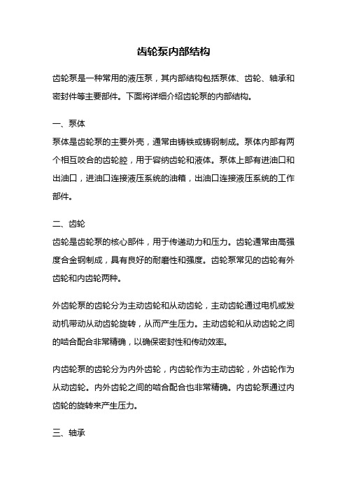
齿轮泵内部结构齿轮泵是一种常用的液压泵,其内部结构包括泵体、齿轮、轴承和密封件等主要部件。
下面将详细介绍齿轮泵的内部结构。
一、泵体泵体是齿轮泵的主要外壳,通常由铸铁或铸钢制成。
泵体内部有两个相互咬合的齿轮腔,用于容纳齿轮和液体。
泵体上部有进油口和出油口,进油口连接液压系统的油箱,出油口连接液压系统的工作部件。
二、齿轮齿轮是齿轮泵的核心部件,用于传递动力和压力。
齿轮通常由高强度合金钢制成,具有良好的耐磨性和强度。
齿轮泵常见的齿轮有外齿轮和内齿轮两种。
外齿轮泵的齿轮分为主动齿轮和从动齿轮,主动齿轮通过电机或发动机带动从动齿轮旋转,从而产生压力。
主动齿轮和从动齿轮之间的啮合配合非常精确,以确保密封性和传动效率。
内齿轮泵的齿轮分为内外齿轮,内齿轮作为主动齿轮,外齿轮作为从动齿轮。
内外齿轮之间的啮合配合也非常精确。
内齿轮泵通过内齿轮的旋转来产生压力。
三、轴承轴承安装在泵体内部,用于支撑齿轮的旋转。
轴承通常采用滚动轴承,具有较高的承载能力和较低的摩擦损失。
为了保证齿轮泵的正常运行,轴承需要保持充分润滑。
四、密封件密封件用于保持齿轮泵的密封性,防止液体泄漏。
常见的密封件有轴封、填料密封和间隙密封等。
轴封通常由橡胶或聚氨酯制成,填料密封使用填料填充泵体和轴封之间的间隙,间隙密封则通过间隙的设计来实现密封效果。
五、工作原理齿轮泵的工作原理是通过齿轮的旋转将液体吸入泵体的一个齿轮腔,然后将液体挤出泵体的另一个齿轮腔。
在齿轮腔内,液体会被齿轮牵引并形成密封,从而形成一定的压力。
齿轮泵的压力和流量与齿轮的旋转速度和齿轮的啮合配合有关。
总结:齿轮泵的内部结构包括泵体、齿轮、轴承和密封件等主要部件。
泵体是齿轮泵的外壳,齿轮是齿轮泵的核心部件,轴承用于支撑齿轮的旋转,密封件用于保持泵的密封性。
齿轮泵通过齿轮的旋转来产生压力,实现液体的吸入和排出。
齿轮泵结构简单、可靠性高,广泛应用于液压系统中。
CBB系列低压齿轮油泵参数及规格

CBB系列低压齿轮油泵参数及规格低压齿轮油泵是一种常用的液压设备,具有结构简单、体积小、重量轻、输出流量大等特点。
CBB系列低压齿轮油泵作为一款经典型号,其参数和规格如下:型号:CBB系列低压齿轮油泵工作压力:0-16MPa流量范围:0-100L/min转速范围:500-3000 rpm油箱容量:1.5-12L电机功率:0.37-3.0kW电源电压:220V/380V噪音水平:≤75dB工作温度:-20°C~60°CCBB系列低压齿轮油泵的主要结构由泵体、传动轴、前后端盖、齿轮、油封等组成。
泵体采用高强度铁铸造或铸钢制作,具有优良的抗压能力和抗磨损性能。
传动轴为优质合金钢材料制作,经过精密加工和热处理,具有良好的强度和耐磨性。
前后端盖采用铝合金材料制作,重量轻且具有良好的密封性。
齿轮为高硬度合金材料制作,经过精密研磨和热处理,具有良好的耐磨性和噪音低等特点。
油封采用高质量的橡胶材料,具有良好的密封性能。
1.结构紧凑,体积小,重量轻,易于安装和维护。
2.输出流量大,工作效率高,节能环保。
3.噪音低,运行平稳,使用寿命长。
4.适用于多种工况,可以在恶劣的环境下正常工作。
5.可根据客户需求进行定制,满足各种特殊要求。
CBB系列低压齿轮油泵广泛应用于冶金、矿山、船舶、建筑机械、农机等行业的液压系统,主要用于润滑、传动和控制液压油的输送。
通过与液压马达、液压阀等设备配合使用,形成一个完整的液压系统,实现各种工作机构的动力传递和控制。
总结:CBB系列低压齿轮油泵具有结构简单、工作可靠、体积小、流量大等特点,在液压系统中得到广泛应用。
其参数和规格的丰富选择,使其适应各类工况和需求。
齿轮油泵零件分析报告
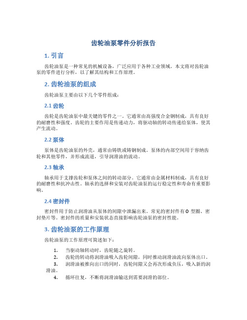
齿轮油泵零件分析报告1. 引言齿轮油泵是一种常见的机械设备,广泛应用于各种工业领域。
本文将对齿轮油泵的零件进行分析,以了解其结构和工作原理。
2. 齿轮油泵的组成齿轮油泵主要由以下几个零件组成:2.1 齿轮齿轮是齿轮油泵中最关键的零件之一。
它通常由高强度合金钢制成,具有良好的耐磨性和强度。
齿轮的主要作用是传递动力,将驱动轴的转动传递给泵体,使其产生流动。
2.2 泵体泵体是齿轮油泵的外壳,通常由铸铁或铸钢制成。
泵体的内部空间用于容纳齿轮和其他零件,并形成流道,引导润滑油的流动。
2.3 轴承轴承用于支撑齿轮和泵体之间的转动部分。
它通常由金属材料制成,具有良好的耐磨性和抗冲击性。
轴承的选择和安装对齿轮油泵的运行稳定性和寿命有重要影响。
2.4 密封件密封件用于防止润滑油从泵体的间隙中泄漏出来。
常见的密封件有O型圈、密封垫片等。
密封件的质量和安装状态直接影响齿轮油泵的密封性能。
3. 齿轮油泵的工作原理齿轮油泵的工作原理可简述如下:1.当驱动轴转动时,齿轮随之旋转。
2.齿轮的转动将润滑油吸入齿轮间隙,同时推动润滑油流向泵体出口。
3.润滑油被推向出口的同时,齿轮间隙又会再次形成负压,吸入新的润滑油。
4.循环往复,不断将润滑油输送到需要润滑的部位。
4. 齿轮油泵的常见问题和解决方法在使用齿轮油泵的过程中,可能会遇到一些常见问题,如泄漏、噪音等。
以下是一些常见问题的解决方法:4.1 泄漏泄漏是齿轮油泵常见的故障之一。
造成泄漏的原因可能是密封件损坏或安装不当。
解决方法包括更换密封件、调整密封件的安装状态等。
4.2 噪音齿轮油泵在工作过程中可能会产生噪音,主要原因是齿轮间隙不当或磨损严重。
解决方法包括调整齿轮间隙、更换磨损严重的零件等。
5. 结论本文对齿轮油泵的零件进行了分析,了解了齿轮油泵的结构和工作原理。
同时,还介绍了常见问题的解决方法。
通过这些分析和了解,可以更好地使用和维护齿轮油泵,确保其正常运行和延长使用寿命。
齿轮式的油泵工作原理

齿轮式的油泵工作原理
齿轮式油泵是一种常用的液压传动装置,它通过两个互相啮合的齿轮,将输入轴的旋转运动转换为输出轴的流体运动,从而实现液压油的输送。
齿轮式油泵的工作原理如下:
1. 齿轮和轴:齿轮式油泵通常由一个带齿的齿轮和一个旋转的轴组成。
其中,输入轴通过外力传递输入的旋转动力,使齿轮旋转。
2. 齿轮间的啮合:齿轮的齿形使其能够与另一个齿轮进行啮合。
输入轴的旋转使得齿轮旋转,并且由于两齿轮之间的啮合,其转动速度和方向相同或相反。
3. 油腔和吸油:齿轮式油泵通常具有齿轮和泵壳之间的油腔。
在齿轮旋转时,油腔会形成一个部分密闭的空间,从而产生负压。
这个负压将液压油从进油口吸入到齿轮间的密闭空间。
4. 油液的挤出:当齿轮继续旋转时,液压油被挤出油腔,并通过出油口流出。
齿轮旋转过程中,因为两齿轮之间的啮合和齿轮与泵壳之间的密闭性,液压油在齿轮齿间被密封和压缩,使得油液能够顺利地被挤出。
5. 油液输送:通过连续的齿轮啮合和运动,液压油可以连续地被吸入和挤出,从而实现油液的输送。
输出轴会带动传动装置或液压系统的工作部件,实现液压动力的传递和转换。
总结起来,齿轮式油泵的工作原理是通过输入轴的旋转,带动齿轮的旋转,从而产生负压吸入液压油,然后通过齿轮的旋转运动将液压油挤出,并通过输出轴输送到需要的位置,实现液压动力的传递和工作。