SAE AS 407D-2012燃油流量表
美孚格兰德研磨油24 安全数据表说明书

修订日期: 28 五月 2021SDS 编号:7102817XCN 最初编制日期: 9 August 2016版本:2.05______________________________________________________________________________________________________________________化学品安全技术说明书产品产品名称: 美孚格兰德研磨油 24产品简介:烃类及添加剂产品代码: 20157020A070, 662130推荐用途: 金属加工液公司资料供应商:埃克森美孚( 中国 )投资有限公司美罗大厦17楼天钥桥路30号上海市 200030 中国二十四小时应急电话供应商联系电话电子邮件传真供应商: 埃克森美孚化工商务(上海)有限公司紫星路1099号闵行区上海市, 中国中国二十四小时应急电话供应商联系电话电子邮件传真紧急情况概述:物理状态: 液体颜色: 褐色气味: 特有的H304:吞咽及进入呼吸道可能致命。
H411:对水生生物有毒并具有长期持续影响。
高压射向皮肤可能会造成严重的损伤本产品在某些应用场合可能会产生油雾。
过度暴露于液体和油雾时可能会引起皮肤修订日期: 28 五月 2021SDS 编号:7102817XCN 最初编制日期: 9 August 2016版本:2.05______________________________________________________________________________________________________________________及眼睛刺激。
此外,暴露于过多的油雾可能导致呼吸刺激与损伤,并加重原有的肺气肿或哮喘。
反复接触可能使皮肤干燥或龟裂。
该物料的危险性分类与化学品分类和危险性公示通则(GB 13690-2009)一致。
GHS危险性类别:吸入毒物:类别1.急性水生生物毒物:类别2 慢性水生生物毒物:类别2标签要素:象形图:警示词:危险危险性说明健康: H304:吞咽及进入呼吸道可能致命。
某型航空发动机燃油流量调节器建模与故障仿真

A src: naregn ul eua rw st e stersac betadi ahma cl dl a s bi e codn b t tA eoniefe rglt a k na eerhojc n t m te ta moe w set lhdacri t a o a h , s i a s go
一
U
一
, V UIn .vVt a ll ;1aIr n l3 a …l. g 3ttj l ja l 乙 Ia C N i — u t U y
,
Re rsnaieOfc n Xi n 1 0 1 Chn ; .h 1 1 t i o P A, h n o gYa ti 6 0 1 Chn ) p ee tt f ei Xi , 7 0 2 , i a 4 t e9 2 3hUnt f L S ad n na v i n a a 2 4 0 , i a
关键词 : 油流量调 节器 ; 燃 转速控制器 ; 压差控制器; 小波 ; 油特性 ; 空发 动机 供 航
M o e ig a d F utSi ua in o n Ae o n ie F e g lt r d l n a l m lt fa r e g n u l n o Re uao
i rn i l n h sc ls u t r . h e td t t e t i t t s i tr d y h v l t h o r cn s f h d lw s v r i t p c p e a d p y ia t cu e T e ts aa a ran sae wa f e e b t e wa ee . e c re t e s o t e mo e a ei d s i r c l T f b i l t g T et p c l a l f u lr g lt rw r n lz d a d t e ols p l r i l td i h al r d fa i g d a h a m, ys mu ai . h y ia ut o e e u ao e e a ay e n h i u p y we e s n f s f mu ae n t e f i e mo e o g n i p r g u v r b e me s r me t h l a n l g i g h ac lt n r s l h w t a h f c f t e v r b e me s r me th l e r a d a i l a u e n oe we r a d c o gn .T e c l u ai e u t s o h tt e e f t o h a i l a u e n oe w a n a o s e a co g n n t e ol s p l h r ce it s i sg i c n ,b t t e ef c f t e a i g d a h a m n t e ol s p l h r ce si s i n t lg i g o h i u p y c a a t r i s in f a t u h fe to h gn ip r g O h i u p y c a a tr t s o sc i i c o vo s b iu .
石油试验检测仪器设备
石油试验检测仪器设备介绍石油试验检测仪器设备是石油行业中必不可少的工具,用于测试和评估石油产品的质量和性能。
这些设备帮助石油公司和实验室确定石油产品是否符合行业标准和规定,以及检测潜在的质量问题。
常见的石油试验检测仪器设备以下是一些常见的石油试验检测仪器设备:1. 密度计:用于测量石油产品的密度,以确定其质量和纯度。
2. 粘度计:用于测量石油产品的粘度,以评估其流动性和可用性。
3. 硫含量分析仪:用于分析石油产品中的硫化物含量,以确定其环境影响和燃烧性能。
4. 水分析仪:用于分析石油产品中的水分含量,以检测可能的污染问题。
5. 闪点测定器:用于确定石油产品的闪点,以评估其燃烧安全性。
6. 残炭测定器:用于测量石油产品中的残炭含量,以确定其燃烧效果和污染问题。
这些仪器设备的使用需要专业的操作人员,以确保准确和可靠的测试结果。
重要性和应用领域石油试验检测仪器设备在石油行业中起着至关重要的作用。
1. 生产过程控制:这些仪器设备可用于监控石油产品生产过程中的关键参数,确保产品的一致性和质量。
2. 进口和出口质量检验:在国际贸易中,石油产品的质量是决定是否能被接受和交付的重要指标。
这些仪器设备可用于检验进口和出口石油产品的质量。
3. 环境保护:通过检测石油产品中的污染问题和环境有害成分,这些仪器设备对环境保护和可持续发展起着关键作用。
4. 科学研究和开发:石油试验检测仪器设备提供了科学研究和开发石油产品的基础数据和指导,为新产品的设计和改进提供支持。
总结石油试验检测仪器设备是石油行业的关键工具,帮助确定石油产品的质量和性能。
通过控制生产过程、质量检验和环境保护,这些仪器设备对石油行业的发展和可持续性起着重要作用。
对于任何从事石油业务的公司和实验室来说,拥有和正确使用这些仪器设备是至关重要的。
塞纳斯飞行仪表
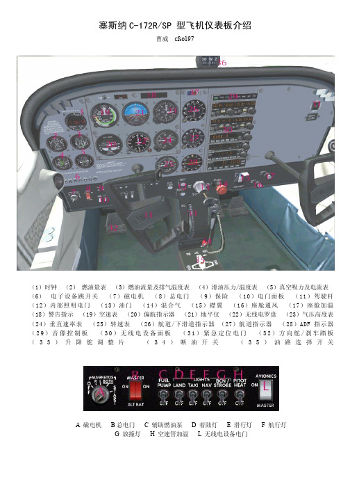
塞斯纳C-172R/SP 型飞机仪表板介绍
曹威cfso197
(1)时钟(2)燃油量表(3)燃油流量及排气温度表(4)滑油压力/温度表(5)真空吸力及电流表(6)电子设备跳开关(7)磁电机(8)总电门(9)保险(10)电门面板(11)驾驶杆(12)内部照明电门(13)油门(14)混合气(15)襟翼(16)座舱通风(17)座舱加温(18)警告指示(19)空速表(20)偏航指示器(21)地平仪(22)无线电罗盘(23)气压高度表(24)垂直速率表(25)转速表(26)航道/下滑道指示器(27)航道指示器(28)ADF指示器(29)音像控制板(30)无线电设备面板(31)紧急定位电门(32)方向舵/刹车踏板(33)升降舵调整片(34)断油开关(35)油路选择开关
A 磁电机B总电门 C 辅助燃油泵 D 着陆灯 E 滑行灯 F 航行灯
G 放撞灯H 空速管加温L 无线电设备电门
a 左油箱油量
b 右油箱油量
c 排气温度
d 燃油流量
e 滑油温度
f 滑油压力
g 真空吸力
h 电流
由于本人水平有限,如有错误在所难免,望大家给与指正。
无锡恒和环保科技有限公司 W-AAA AA0704-SCR-YUNNEI-G 无锡恒和环保科技有限公
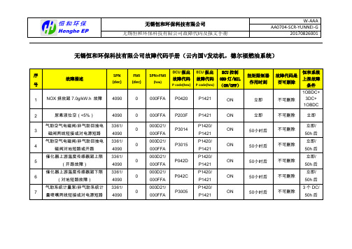
无锡恒和环保科技有限公司故障代码手册(云内国V发动机,德尔福燃油系统)
无锡恒和环保科技有限公司故障代码手册(云内国V发动机,博世燃油系统)
DCU接收解析的ECU及NOx传感器提供的报文
Fuel Economy - LFE
Electronic Engine Controller 1 - EEC1
Electronic Engine Controller 2 - EEC2
Ambient Conditions - AMB
Engine Temperature 1 - ET1
具体参数:
Electronic Engine Controller 3 – EEC3
Cruise Control/Vehicle Speed - CCVS
具体参数:
Vehicle Distance - VD
具体参数:
Inlet/Exhaust Conditions 1 - IC1
NOx浓度和O2浓度
具体参数:
DCU发出的信息包括液位信息与故障OBD信息
尿素液位
NOx传感器加热启动(Electronic Engine Controller 3 – EEC3)
具体参数:
SAE J1939标准的故障信息DM1
参考:
云内博世ECU发送报文列表
TX—发送报文(Transmitting Messages)
发送报文汇总列表1.1:
ECU接收报文列表RX—接收报文(Receiving Messages)
接收报文汇总列表2.1:。
美格尔自动油液测试仪产品说明书

OTS60PB, 60AF/2, 80AF/2, 100AF/2, VCM100 Automatic Oil Test SetsDESCRIPTIONThe Megger range of automatic oil testers offer fully automatic testing with many advanced features. The design allows the operator to simply prepare an oil test vessel, load it with the sample oil, place it in the chamber and initiate the test sequence. The test set then carries out, the series of tests as specified in a large number of oil testing specifications. These define the sequence of tests including the stand and stir times, rate of voltage rise and number of tests resulting in a calculation of the average value of the oil breakdown strength. Withstand or proof testing can also be selected. This test subjects the oil to a preselected voltage for 1 minute to check for a breakdown.The OTS60PB is a fully automatic, battery powered, portable oil test set. The test voltage is electronically controlled to the maximum of 60 kV.Designed for on site testing, the instrument is supplied in a rugged carrying case with a handle for ease of transportation. An internal rechargeable battery gives a large number of tests before recharging. A clear display shows a menu of test options and guides the operator through the set up programme, illustrates the correct test electrodes and gap to use, shows the progress of each test and gives the results of the test sequence. The result can be set to give either a numerical average (with standard deviation where specified) or a pass/fail message. The display can be set to read in English, French, German, Italian, Spanish and Portuguese. An optional printer kit enables hard copies of results to be produced. Accessories, such as the battery charger,spare vessels, spare electrodes and a spacing gauge are located in an attached compartment. Stirring is carried out by a motor driven paddle stirrer.The OTSAF/2 range are laboratory instruments with many advanced features. Three versions are available with maximum test voltages of 60 kV,80 kV and 100 kV.They offer fully automatic operation plus the benefit of a builtin printer to produce a hard copy of the test results andthe ability to program up to five user defined tests for individual applications. The withstand test can be set to operate at any test voltage and with an initial stand time. The dot matrix liquid crystal display can also be set toread in one of six languages. An oil test vessel, configured to suit the IEC156 test specification, is supplied with the instrument.A large, backlit, liquid crystal display shows test menus,set up screens and results. The resolution of the high voltage output is displayed to 0,1 kV.Results can be printed on the internal dot matrix printer or transferred via the RS232 interface to an external printer or PC. Printouts are automatically time and date stamped. Standard stirring with the OTSAF/2 is achieved by a magnetic stirrer bar.Additional vessels are available optionally, including one suitable for testing to the ASTMD1816 specification. This calls for stirring to be carried out by a motor driven impeller. Each test can be selected with either magnetic stirring, propeller stirring or no stirring. The VCM100 is a calibration meter suitable for verifyingthe calibration of oil test sets. The meter will enable thes Microprocessor controlled fully automatic oil test setss Wide choice of vessels and accessoriess Portable and laboratory unitsSPECIFICATIONPanel meter scaling0Accuracy±3% of full scaleTemperature RangeOperational0°C to 40°C (32 to 104°F)Storage-30°C to +70°C (-22 to 158°F)Humidity RangeOTS VCM100 Scale Plate(programmed in OTS60PB, OTS60AF/2, OTS80AF/2 and OTS100AF/2)Intermediate Number Maximum Duration of SelectedStand Time Of T ests test sequenceOTS60BOTS60PB OTS60AF/2, OTS80AF/2 AND OTS100AF/2Electrode Shape B12,7 mm (0,5 in) Spherical Electrodes Electrode Shape D25,4 mm (1 in) Cylindrical Electrodeswith 0,5mm edge radiusPRINTER INFORMATIONThe OTS60PB Printer Kit includesa24 column impact printer withintegral rechargeable batteries anda mains adaptor which operatesfrom 85 V to 265 V a.c. (50/60 Hz).The printer is 105 mm x 195 mmx90 mm and weighs 625 g.UKArchcliffe Road Dover CT17 9EN EnglandT+44 (0) 1304 502101 F+44 (0) 1304 207342UNITED STATES4271 Bronze WayDallas TX 75237-1088 USAT800 723 2861 (USA only)T+1 214 333 3201F+1214 331 7399OTHER TECHNICAL SALES OFFICESNorristown USA, Toronto CANADA,Mumbai INDIA, Trappes FRANCE,Sydney AUSTRALIA, Madrid SPAINand the Kingdom of BAHRAIN.Registered to ISO 9001:2000 Cert. no. Q 09290Registered to ISO 14001-1996 Cert. no. EMS 61597OTS_AF_AUTO_DS_en_V11Megger is a registered trademark。
塞尔瑟斯-流量表SAIL-F8-2-0-2-12-N-W_CN

Loc=1234 时,在测量显示状态下,按“ ”键可看到清零次数参数“L”及相应的数值 2、仪表测量显示设定参数( FSn、FdiP、FdiL、FdiH、Sc、Fi、dL、CHo、PF、CF)
仪表每年应进行一次计量检定,如果仪表误差超出范围,通常都是由于潮湿、灰尘或腐蚀气体所 导致,可对仪表内部进行清洁及干燥处理,通常这样都能解决问题,尽量不要采用修改 SC 参数的方法 来进行修正仪表误差。本系列仪表是一种免维护仪表,不提供用户重新校正仪表的操作,它采用自动调 零技术可长期使用不会产生任何零漂,采用数字校正技术则消除了稳定性较差的可调电阻,所以仪表本 身不会因使用时间增加而产生误差,如果干燥和清洁无法恢复精度,应将此仪表视同故障仪表送回厂方 检修。
SAIL-F 系列仪表可任意选择开方/不开方功能;具有 8 位累积量和 4 位瞬时量显示,并可选择自动 切换或手动切换;具有小信号切除功能;具有累积流量断电保存功能;具有定量控制功能。
SAIL-F 系列仪表具有多类型输入功能,一台仪表可以接不同的输入信号(0~5V、1~5V、0~10mA、 4~20mA 等), 大大减少了备表的数量。使其适用范围更加广泛,可与各类模拟量流量传感器、变送器 配合使用,实现对流量的测量显示、报警控制、数据采集、记录。
(4) SC 用于设定仪表对输入信号的平移修正值,以补偿传感器或输入信号本身的误差。SC 参数与 显示呈对应关系。
例:当前显示值为 0.5,但实际值应为 0.0,其中差值为+0.5,则在修正时将 SC1 设置为-0.5, 这时,显示值将变为 0.0。 注:仪表出厂时都进行过内部校正,所以 Sc 参数出厂时数值均为 0。该参数仅当用户认为 测量需要重新校正时才进行调整。
USCAR-2(中文第5版)-2009[1].03.17
![USCAR-2(中文第5版)-2009[1].03.17](https://img.taocdn.com/s3/m/9b749d5be87101f69e319588.png)
研究数据、分析、结论、观点和本文的其他内容仅仅是作者的产品。
无论是汽车工程师协会(SAE)还是美国汽车研究委员会(USCAR)都不会出具任何证明某些产品符合基本要求的证书,也不会对本文内容的准确性和适用性作任何介绍。
确定本文内容是否适用于自己的目的,完全是本文用户责任。
版权 2004, USCAR 美国印刷
版权所有
有关本文件的问题: (724) 772-8545 传真 (724)776-0243
要订购文件: (724) 776-4970 传真 (724) 776-0790
Lock overtravel
Forward stop contacted
向前止动接触
Decreasing
Recognizable travel
distance
如果有适用的设备,强烈建议绘制所施加的啮合力与插入距离之间的连续对照图。
个结构合理的连接器(和密封系统,如适用的话) 应当能够绘制出一张图,其中显示
力平稳上升至一个峰值,然后下降直至连接器完全啮合。
如果图中显示一个以上的力
的峰值,锁止机构就可能存在错误。
第五修订版修订日期:
汽车电器连接器系统的性能标准
+/-10毫米/分的速率增加啮合力,直至完全啮合为止。
试验所有样品.记录将每一套连接器的一半完全插入另外一半,直至锁定位置所需要使用的力并且用这些数值来验证每一对连接器是否符合5.4.2.4 章节的验收标准。
石油分析仪器使用说明书

石油分析仪器使用说明书使用说明书1. 石油分析仪器概述石油分析仪器是一种用于测试和分析原油、石油产品以及相关样品的专用设备。
本使用说明书旨在详细介绍石油分析仪器的操作步骤和注意事项,以确保用户能够正确、安全地使用该仪器。
2. 安全操作指南2.1 仪器操作前的准备在操作仪器之前,确保所处环境稳定、整洁,并检查仪器是否完好。
如遇到异常情况或仪器故障,请联系专业维修人员进行维护。
2.2 个人防护措施在操作仪器时,建议佩戴合适的个人防护设备,如手套、护目镜等。
同时,注意避免直接接触样品,避免产生有害物质飞溅。
2.3 电源及电气安全仪器应连接至稳定的电源,并请勿触摸电器部件,以免发生触电危险。
如发现电气故障或线缆破损,请立即停止使用并联系售后服务。
3. 仪器操作步骤3.1 样品准备将待测样品按照要求准备好,并确保样品不受污染。
若需要稀释或配制试剂,请按照标准程序进行。
3.2 仪器开机与校准连接仪器电源,并按照操作界面上的提示进行开机操作。
根据仪器要求,进行校准步骤,确保仪器的准确度和稳定性。
3.3 样品测试将样品放置在仪器的测试台上,并按照操作界面上的指示选择相应的测试方法。
启动测试程序后,等待仪器自动完成测试。
3.4 数据分析与记录仪器完成测试后,将自动显示测试结果,并可导出为数据文件。
根据需要,用户还可将结果打印或保存到电脑或其他存储设备上进行进一步分析和比较。
4. 维护与保养4.1 定期清洁根据使用频率,定期对仪器进行清洁,以保持其正常运行和延长使用寿命。
使用柔软的湿布和专用清洁剂擦拭外壳和测试台面。
切勿将清洗剂直接喷洒到仪器内部。
4.2 保养注意事项在使用过程中,应注意仪器的散热、防尘和防潮。
避免长时间进行连续测试,以免过度使用导致仪器损坏。
若发现仪器有异常噪音或异常操作,请及时联系售后服务。
4.3 维修与更换部件在需要维修或更换仪器部件时,务必由专业人员进行操作。
若需要更换零部件,请使用原厂配件,以确保仪器的正常运行。
Saia-Burgess空调系统用户手册说明书

- 6 -WEEE Directive 2012/19/EC Waste Electrical and Electronic Equipment directiveAt the end of the product life dispose of the packaging and p roduct in a corresponding recycling centre. Do not dispose of the unit with the usual domestic refuse.Do not burn the product !RECOMMENDATIONS AND RULES►Rules regarding electrostatic discharge should be followed. ►If the device is modified in any way, except by the manu -facturer, all warranties concerning operation and safety are invalidated.►Make sure that the local standards and regulations areobserved at all times. Examples of such regulations are VDE 0800 and VDE 0100 or EN 60204-1 for earth grounding.►Use only accessory equipment which comes from or has been approved by Honeywell.►It is recommended that the device be kept at room temper-ature for at least 24 hours before applying power. This is to allow any condensation resulting from low shipping / storage temperatures to evaporate.►The device must be installed in a manner (e.g., in a lockable cabinet) ensuring that uncertified persons have no access to the terminals.►Do not open the device, as it contains no user-serviceable parts inside!►The device is suitable for mounting in fuse boxes conforming to standard DIN 43880, and having a slot height of max. 45 mm.►The device is suitable for panel rail mounting on 35 mmstandard panel rail (both horizontal and vertical rail mounting possible) – see pictures 0G and 0H.STANDARDS, APPROVALS, ETC.PURPOSE OF CONTROL: OPERATING CONTROL and multifunctional non-safety control intended for HVAC in home (residential, commercial, and light-industrial) environments ■24 V models:UL 60730-1, Standard for Automatic Electric Controls for Household and Similar Use, Part 1: General Requirements ■CE-approved■FCC part 15B-compliant.CONSTRUCTION OF CONTROL: Independently mounted electronic control unit with fixed wiring. Panel-mounted on a DIN rail.SHOCK PROTECTION: Class II.POLLUTION DEGREE: 2.RATED IMPULSE VOLTAGE: ■230 V circuits: 2500 V ■ 24 V circuits: 500 V NOTE:K eep AC mains supply/load cables separate from signal wiring!RELAY SPECIFICATIONSCAUTIONRISK OF ELECTRICAL SHOCK OR EQUIPMENT DAMAGES!It is not permitted to combine low voltage and line voltage in the relay block.MU1B-0643GE51 R0418C - 5 -Saia Burgess Controls AGPCD7.LRxx-P5 PG5 ROOM CONTROLLER - MOUNTING INSTRUCTIONS EKeep these instructions together with the device or with the equip-ment documentation!FCette instruction est à conserver avec le contrôleur ou avec la docu-mentation de l’installation !PGuarde estas instruςões junto do regulador ou junto da documentaςão da instalaςão!D Diese Anleitung ist beim Gerät oder in der Anlagendokumentation aufzubewahren!IQueste istruzioni devono essere conservate insieme al lettore o con la documentazione dell´impianto!S Denna instruktion skall förvaras tillsammans med regler eller anlägg-ningsdokumentationen!DKOpbevar denne vejledning sammen med regler eller med anlægsdoku-mentationen!N Denne veiledningen skal oppbev-ares sammen med regler eller anleggs-dokumentasjonen!FITätä ohjetta tulee säilyttää laitteen läheisyydessä tai yhdessä muiden dokumenttien kanssa!ES Conserve estas instrucciones con el recalar con la documentación de la instalación.NL Deze handleiding moet bij de rege-laar, of met de documentatie van de installatie worden bewaard!PLInstrukcję obsługi należy przechowy -wać przy urządzeniu albo w doku -mentacji technicznej.Copyright © 2018 Saia-Burgess Controls AG All Rights ReservedMU1B-0643GE51 R0418CSupportDocumentationMU1B-0643GE51 R0418C - 4 -Saia Burgess Controls AG PCD7.LRxx-P5 PG5 ROOM CONTROLLER - MOUNTING INSTRUCTIONS2. D IN-RAIL MOUNTING PCD7.LRxx-P5 + MOUNTING IRM-RxC3. DISMOUNTING IRM-RxC + DISMOUNTING PCD7.LRxx-P5 from DIN-RAILMU1B-0643GE51 R0418C - 3 -Saia Burgess Controls AG PCD7.LRxx-P5 PG5 ROOM CONTROLLER - MOUNTING INSTRUCTIONS- 2 -Saia Burgess Controls AG PCD7.LRxx-P5 PG5 ROOM CONTROLLER - MOUNTING INSTRUCTIONS MU1B-0643GE51 R0418C。
安德森电磁流量表说明书

Anderson Instrument Co.,Inc.156Auriesville Rd.~Fultonville,NY 12072Phone:518-922-5315~Fax:518-922-8997Reach us on the World Wide WebThis product carries a one (1)year warranty against manufacturers defects.A complete warranty statement is available by contacting Anderson,or in downloadable formatfrom the World Wide Web.Installation and Startup GuideModel IZML ElectromagneticFlowmeterVersion 2.1Document 1132READ THIS FIRSTSPECIFICATIONSORDER MATRIXPRODUCT DESCRIPTIONThe Anderson IZML Flowmeter is a precision instrument that mounts directly to the process line,and provides real-time information about the process.The IZML measures voltage generated from conductive product passing through an electromagnetic field.The resulting information that the IZML generates can be used to provide an instantaneous indication of the rate of a liquid or collected over time to indicate a total of what has passed through the pipe.Using the above operating principals,the IZML can accurately provide outputs for control or indication of the flow process.Flow TubeOutput OptionIZ 0155/8"Flow tube 0251"Flow tube 0321-1/4"Flow tube 0502”Flow tube 0652.5”Flow tube 0803”Flow tube 1004”Flow tube024VDC1115VAC 50/60Hz 2230VAC 50/60HzM LDisplay OptionO No Display D Display OptionOperating Power0No Analog Output1Analog Output -Active Output2Analog output -P assive Output w/HART Meter Length0Standard 13.25"1Optional 9.88"2Optional 3/4"T.C.on IZML015length 10.5"34”Tri-Clamp®connection for IZML1007Cherry I-line connection 13”OperationalMaterial /Construction Ambient Temperature:5F to 131F (-15C to 55C)Maximum Product Temp:176F /80CMaximum Cleaning Temp:250F/120C for 30minutes Maximum Inlet Pressure:144psi /10bar Minimum Fluid Conductivity:5S /cmHousing:304stainless steelLining:PTFE (non-filled virgin Teflon®)Electrodes:316L stainless steelHousing:Cast aluminum with corrosion-resistant coating (IP67)Process Connection:Sanitary ClampµElectronicsElectrical Supply:16-34VDC (.4-..2A)115V/230V 50-60Hz(0.10A /0.05A)-15%/+10%P ower Consumption:10VA /6watt maximumMagnetic Field:DC pulsed with self-adapting adjustment Digital Pulse Output:1x Opto-isolated.Load:30V@80mA max.,1,000Hz Analog Output (optional):4-20mA (active)500ohms maximumDigital Input:1x Opto-isolated.Activation:30V@10ma 10Hz maximum Display:2line back litUNPACKINGProduct Check:Upon receipt,carefully inspect the product for damage to connectors and sensor face.Damage claims should be made direct with carrier.Major items are:·IZML configuration record sheet·meter body with connection adapters assembled to the flow tube ·cord grips ·manualIZML INSTALLATION5x PIPE DIAMETER MINIMUM2x PIPE DIAMETER MINIMUM2x PIPE DIAMETER MINIMUM5x PIPE DIAMETER MINIMUMInstall meter body in-line with arrow decal matching direction of flow.Install in process line with orientation to ensure flow tube remains full.Do not install meter body where vacuum conditions may exist that could collapse the Teflon liner.Avoid installing the meter body next to equipment emitting strong electromagnetic fields that could distort the magnetic field generated by the flowmeter and cause measuring errors.Pipeline must be properly grounded,or earth ground can be landed to the flow tube lug.xxxxxxxxxxxxxxxxxxxxxxxxx xxxxxxxxxxxxxxxxxxxxxxxxx xxxxxxxxxxxxxxxxxxxxxxxxx xxxxxxxxxxxxxxxxxxxxxxxxx xxxxxxxxxx xxxxxxxxxx xxxxxxxxxxxxxxxxxxxxxxxxxxxx xxxxx xxxxx xxxxxxxxxx xxxxx xxxxxxxxxxxxxxxxxxxxxxxxxxxxxx xxxxxxxxxxxxxxxxxxxxxxxxx xxxxxxxxxxxxxxxxxxxxxxxxx xxxxxxxxxxxxxxxxxxxxxxxxxxxxxxxxxxx xxxxxxxxxx xxxxxxxxxxxxxxxxxxxxxxxxxxxx xxxxx xxxxx xxxxxxxxxx xxxxx xxxxxxxxxxxxxxxxxxxxxxxxxxxxxx xxxxxxxxxxxxxxxxxxxxxxxxx xxxxxxxxxxxxxxxxxxxxxxxxx xxxxxxxxxxxxxxxxxxxxxxxxxxxxxxxxxxx xxxxxxxxxx xxxxxxxxxx xxxxxxxxxxxxxxxxxxxxxxxxxxxxxxxxxxxxxxxxxxx xxxxx xxxxxxxxxxxxxxxxxxxxxxxxx xxxxxxxxxxxxxxxxxxxxxxxxx xxxxxxxxxxxxxxxxxxxxxxxxx xxxxxxxxxxxxxxxxxxxxxxxxxxxxxxxxxxx xxxxxxxxxx xxxxxxxxxxxxxxxxxxxxxxxxxxxx xxxxx xxxxx xxxxxxxxxx xxxxx xxxxxBefore welding on a pipline with a flowmeter installed,disconnect the signal electrode wires from the meter body at terminals 14,16,and 18at the convertor.Make all converter connections prior to applying AC power.Warning:CALIBRATIONHydraulic Zero Adjustment without DisplayHydraulic Zero Adjustment with DisplaySimulated Output Procedure without displayT Simulated Output Procedure with DisplayUtilizing the following procedure will establish a no flow reference point compliant with the specific hydraulic conditions of the application.1.Allow 5minutes for the flowmeter to warm up to operating temperature.In order to maintain thermal stability,Close but do not tighten the convertor cover during the hydraulic zero adjustment procedure,except when access to the convertor is necessary to press buttons or observe the LED status.2.Fill the flow tube of the meter body with liquid or water.The electrical conductivity of the product must be greater than 100micromhos.It is essential that the fluid remain static (no flow or leakage whatsoever)and there is no entrained air in the product during the hydraulic zero adjustment procedure.3.Press the Zero Adjust pushbutton (Identified on page 3of the Startup Guide)momentarily (about two seconds)and then release.4.Wait 40seconds for the completion of the hydraulic zero adjustment period.5.Observe Green status LED (Identified on page 3of the Startup Guide).Light will change from a continuously on state to a blinking state during the hydraulic zero adjustment procedure.Once the zero procedure is complete the green light will momentarily be off,then return to a continuously on state.6.If Red status LED (Identified on page 3of the Startup Guide)remains on after zero adjustment,check terminal connections 11-18for proper connection..Return to Step 3and repeat Hydraulic adjustment procedure.1.Follow steps 1and 2listed of the "Hydraulic Zero Adjustment without Display"instructions.2.Press "M">"Enter">"Right Arrow">"Enter".Display will indicate "codeno:____".Enter code "415"using the UP Arrow to increment,and the "Right Arrow"to toggle position.Press enter.3.Display will count down from 100%,then display "New Zero value".Press "Enter"and return to operation display.4.Confirm the successful hydraulic zero adjustment by visually inspecting Green and Red LED status listed of the "Hydraulic Zero Adjustment without Display"instructions.he IZML flowmeter offers the ability to test signal communication with a receiving device prior to flowing product.1.Place switches 3,7,and 8from the S6parameter switch (Identified on page 3of the Startup Guide)to the on position.2.Press the Abort pushbutton (Identified on page 3of the Startup Guide)momentarily (about two seconds)and then release.3.Observe Amber status LED(Identified on page 3of the Startup Guide).Light will blink a Place switches 3,7,and 8from the S6parameter switch (Identified on page 3of the Startup Guide)to the off (number indicated position).7.Press the Abort pushbutton (Identified on page 3of the Startup Guide)momentarily (about two seconds)and then release.8.IZML will return to operational state.1.Press "M">"Enter">"Right Arrow">"Down Arrow">"Down Arrow".Display will indicate "function 2/simulation".Press "Enter".Display will indicate "codeno:____".Enter code "415"using the UP Arrow to increment,and the "Right Arrow"to toggle position.Press enter.2.Display will indicate "simulation /50%value with units per minute".3.Observe Amber status LED(Identified on page 3of the Startup Guide).LED will blink a rate based on configured digital output value,and 50%of the maximum flow rate value indicated on the label of the flowmeter cover Press "Clear"and return to operation display.pproximately once each second.4.Digital pulses are sent at a rate similar to the LED indication.5.Flowmeters with the optional analog will observe 4-20mA output current between 11.97and 12.00mA.6..4.Digital pulses are sent at a rate similar to the LED indication5.Flowmeters with the optional analog will observe 4-20mA output current between 11.97and 12.00mA.6.Press "Up Arrow",and "Down Arrow"modify the rate of simulation.7.。
SAEJ30燃料及油软管
3.4.1合格鉴定试验——为进行合格鉴定试验,每种规格应提供一条7.6m(25英尺)长的未配管接头的软管或10条总成用作合格鉴定。为根据此标准进行鉴定,软管及软管总成必须满足以下试验要求:(a)长度变化,(b)爆破,(c)真空塌陷,(d)低温屈挠,(e)拉伸强度及伸长率,内胶层和外胶层,(f)耐热空气性能,(g)耐燃油性能,(h)耐油性能,(i)耐臭氧性能,以及(j)粘合。
28.58
1.062
1.125
26.97
28.58
1.062
1.125
22.23
7/8
22.23±0.79
0.875±0.031
30.18
31.75
1.188
1.250
25.40
1
25.40±0.79
1.000±0.031
32.54
34.93
1.281
1.375
32.54
34.93
1.281
1.375
第7节包括了中压带接头或不带接头的合成橡胶内胶层及外胶层的燃油喷射软管(SAE 30R9)。
第8节包括了油箱内的、低压、不带接头的燃料软管(SAE 30R10)。
第9节包括了用于燃料软管渗透的标准方法。
第10节包括了低渗透燃料注入及排放软管(SAE 30R11)。
第11节包括了低渗透燃料供给及回流软管(SAE 30R12)。
ASTM D 117-盐浴(Fog)试验方法
ASTM D 257-绝缘材料的DC电阻或导电能力
ASTM D 380-橡胶软管试验方法
ASTM D 412-橡胶拉伸特性试验方法
ASTM D 413-橡胶柔性衬层粘合特性试验方法
ASTM D 471-橡胶特性受流体影响的试验方法
汽车用数显油量表

汽车用数显油量表
王文义
【期刊名称】《电子制作》
【年(卷),期】2005(000)008
【摘要】汽车(或轮船)用油量调位仪表,目前仍绝大部分为模拟指针式仪表,只是大致显示油量油位,要想精确地定量显示根本不可能,再加之传感器部分(油漂浮球原理)系可动构件,极易损坏,所以油量显示很不准确。
为克服上述缺点,一些新型汽车已开始采用数显油量表。
【总页数】1页(P55)
【作者】王文义
【作者单位】山西省晋城市晋城经济技术开发区管委会,048000
【正文语种】中文
【中图分类】U463.837
【相关文献】
1.油研系列品种高含油量表现及高油分高蛋白选育技术研究Ⅰ.油研系列品种在全国和贵州区试中含油量表现 [J], 侯国佐
2.土壤有机质样品前处理简易油浴锅与HH—S型数显恒温油浴锅对比探讨 [J], 杨小珊;李娅萍;赵忠琼
3.利用测井交会图法定量表征致密油储层成岩相——以鄂尔多斯盆地华池地区长7致密油储层为例 [J], 冉冶;王贵文;赖锦;周正龙;崔玉峰;代全齐;陈晶;王抒忱
4.数显油滴测试仪 [J], 武志恩;谢涛
5.电子数显量表的全自动检定仪设计 [J], 吴佳雄;吴佳伟;李自立
因版权原因,仅展示原文概要,查看原文内容请购买。
E-4E 非毒性红色染色石油液温度计说明书

E-4Non-toxic red safety liquid is ideal where mercury is unusable.CONFORMANCERed Safety Discontinued Product Laboratory ThermometersGT Series Starts at$CANADA www.omega.ca Laval(Quebec) 1-800-TC-OMEGA UNITED KINGDOM www. Manchester, England0800-488-488GERMANY www.omega.deDeckenpfronn, Germany************FRANCE www.omega.frGuyancourt, France088-466-342BENELUX www.omega.nl Amstelveen, NL 0800-099-33-44UNITED STATES 1-800-TC-OMEGA Stamford, CT.CZECH REPUBLIC www.omegaeng.cz Karviná, Czech Republic596-311-899TemperatureCalibrators, Connectors, General Test and MeasurementInstruments, Glass Bulb Thermometers, Handheld Instruments for Temperature Measurement, Ice Point References,Indicating Labels, Crayons, Cements and Lacquers, Infrared Temperature Measurement Instruments, Recorders Relative Humidity Measurement Instruments, RTD Probes, Elements and Assemblies, Temperature & Process Meters, Timers and Counters, Temperature and Process Controllers and Power Switching Devices, Thermistor Elements, Probes andAssemblies,Thermocouples Thermowells and Head and Well Assemblies, Transmitters, WirePressure, Strain and ForceDisplacement Transducers, Dynamic Measurement Force Sensors, Instrumentation for Pressure and Strain Measurements, Load Cells, Pressure Gauges, PressureReference Section, Pressure Switches, Pressure Transducers, Proximity Transducers, Regulators,Strain Gages, Torque Transducers, ValvespH and ConductivityConductivity Instrumentation, Dissolved OxygenInstrumentation, Environmental Instrumentation, pH Electrodes and Instruments, Water and Soil Analysis InstrumentationHeatersBand Heaters, Cartridge Heaters, Circulation Heaters, Comfort Heaters, Controllers, Meters and SwitchingDevices, Flexible Heaters, General Test and Measurement Instruments, Heater Hook-up Wire, Heating Cable Systems, Immersion Heaters, Process Air and Duct, Heaters, Radiant Heaters, Strip Heaters, Tubular HeatersFlow and LevelAir Velocity Indicators, Doppler Flowmeters, LevelMeasurement, Magnetic Flowmeters, Mass Flowmeters,Pitot Tubes, Pumps, Rotameters, Turbine and Paddle Wheel Flowmeters, Ultrasonic Flowmeters, Valves, Variable Area Flowmeters, Vortex Shedding FlowmetersData AcquisitionAuto-Dialers and Alarm Monitoring Systems, Communication Products and Converters, Data Acquisition and Analysis Software, Data LoggersPlug-in Cards, Signal Conditioners, USB, RS232, RS485 and Parallel Port Data Acquisition Systems, Wireless Transmitters and Receivers。
- 1、下载文档前请自行甄别文档内容的完整性,平台不提供额外的编辑、内容补充、找答案等附加服务。
- 2、"仅部分预览"的文档,不可在线预览部分如存在完整性等问题,可反馈申请退款(可完整预览的文档不适用该条件!)。
- 3、如文档侵犯您的权益,请联系客服反馈,我们会尽快为您处理(人工客服工作时间:9:00-18:30)。
SAE AS407D 燃油流量表发布日期:基本情况已确定本文件包括基础、稳定且基本不会改变的技术内容。
稳定注释本文件已由SAE 飞机仪表委员会(A-4)宣布处于“稳定”状态,不再接受定期现行有效性审核。
用户负责验证技术要求的引用文件和持续适用性。
可能存在更新的技术。
《国际自动机工程师学会(SAE )技术标准委员会章程》规定:“本报告由SAE 发布,用以促进技术与工程科学的发展水平。
使用本报告完全出于自愿,本报告对于任何特殊用途的可行性和适用性,包括由此引起的任何专利侵权问题,均由使用者个人承担责任。
”SAE 至少每五年对各技术报告审查一次,届时会修订、重申、稳定或废除这些报告。
SAE 欢迎您提出书面意见和建议。
国际自动机工程师学会2012年版权所有。
保留所有权利。
未经SAE 事先书面许可,不允许该出版物的任何部分被复制、存储于检索系统或被以任何形式或任何途径,包括电子、手抄、照片、录音或其他方式等传播。
订购方式:电话: 877-606-7323(美国和加拿大境内) 电话:+1 724-776-4970(美国境外)传真: 724-776-0790 邮箱: CustomerService@ SAE 网址:SAE AS407D 第1页共9页1. 范围本航空标准适用于以下两种指示航空发动机燃油消耗情况的基本类型仪表,或其组合件:类型I——测量燃油流量。
类型II——燃油消耗或剩余总量。
1.1 目的本标准规定了使用活塞发动机的民用运输类飞机的燃油流量表最低要求,仪表的工作应满足3.3规定的环境条件。
2. 引用文件国家航空咨询委员会(NACA)报告12353. 一般要求3.1 材料和工艺3.1.1 材料:应是经使用经验和/或试验证明适用于飞机仪表的可靠优质材料。
3.1.2 工艺:应采用能保持生产高质量飞机仪表的稳定工艺。
SAE AS407D 第2页共9页3.2 标识仪表上或随附的标牌应清晰永久地标出以下内容:a. 仪表名称(燃油流量表)b. SAE(国际自动机工程师学会)航空航天标准AS407Cc. 制造商零件号d. 制造商系列号或制造日期e. 制造商名称和/或商标f. 量程(只对传感器)g. 额定值(电信号—如果需要)3.3 环境条件以下条件仅作为设计要求,试验应按5、6和7章的规定实施。
3.3.1 温度:当按仪表制造厂商的说明安装仪表时,仪表应能在下表中“A”列所列的温度范围内正常工作,且暴露在“B”列所列的温度范围内无有害影响。
表1仪表位置 A B加热区(温控区)-30~50 ℃-65~70 ℃非加热区(非温控区)-55~50 ℃-65~70 ℃动力设备舱-55~70 ℃-65~100 ℃动力设备附件舱-55~70 ℃-65~100 ℃3.3.2 湿度:暴露在温度接近32 ℃相对湿度0~95%范围内时,仪表应正常工作且无不利影响。
3.3.3 振动:当按照仪表制造商说明书安装时,仪表承受下列特性振动时,仪表应正常工作且无不利影响。
SAE AS407D 第3页共9页表2仪表在飞机上的安装位置周/秒最大双峰值(in)最大加速度动力设备支架5~150 0.100 20 g机翼和尾翼5~500 0.036 10 g机身5~500 0.036 5 g仪表板或支架(有减振装置)5~50 0.020 1.5 g3.3.4 高度:除了3.3.1节中规定的仪表限制使用范围外,当按照NACA报告1235使仪表经受相当于从-1000~40,000 ft标准高度的压力和温度时,仪表应正常工作且不能受到不利影响。
当仪表在受到50 in Hg 绝对压力下,仪表应不会受到不利影响。
3.4 无线电干扰在飞机处于任何的无线电工作频率下,流量表均不得以辐射或反馈的形式对安装在同一飞机上的其他电子设备形成有害干扰。
3.5 电磁效应仪表的电磁效应不应对安装在同一飞机上其他仪表的工作产生不利影响。
4. 详细要求4.1 指示方法应使用下列指示方法之一或两种方法的综合方法。
4.1.1 类型I仪表:带有固定刻度表盘的旋转指针或计数类型指示器,顺时针方向的指针运动应表示流量增加。
4.1.2 类型II仪表:计数器应用于表示燃油消耗或剩余量。
4.2 表盘标识4.2.1 表面涂层:除另有规定外,否则主要刻度、数字和指针应使用无光白色涂料。
非工作表面应是耐久的无光黑色。
4.2.2 数字:仪表应标出足够的数字,以便正确和迅速地识别所有的刻度。
数字应能清楚地指示出所示的刻度。
4.2.3 刻度:主要刻度使用的间隔应小于满程值的10%。
4.2.4 计数器:仪表上使用计数器时,其显示值不能超过每10 lbs或2 gal一个增量。
4.2.5 清晰度:指针、所有表盘标识以及计数器应从仪表截头圆锥范围内任一部位皆可观测,该截头圆锥体母线与表盘垂线至少成30°角,其小端直径应为仪表盒的孔径。
表盘与表蒙玻璃之间的距离应为实际可做到的最小值,且不能超过0.25 in。
4.3 流动方向燃油通过传感器的流动方向应永久并清晰地标记在传感器上。
4.4 流量特性除另有规定外,在温度为15~25 ℃,重力加速度为0.715±0.003 g的情况下,使用100辛烷值航空汽油时,流量表的设计应符合本文规定的性能要求。
4.5 电源变化所有仪表在直流电压±15%范围内,或在交流电压±10%范围内,或在频率±5%范围内,应均能正常工作。
4.6 保护设施每个传感器应使用自动旁路或停止供油截流装置提供飞行故障情况下的燃油供应。
5. 试验条件5.1 大气条件除另有规定外,按本航空标准实施的所有试验,要求试验时的大气压力约为29.92 in Hg,环境温度约为25 ℃,相对湿度不大于85%。
当试验时的大气压或温度与上述数值有差异时,应给出偏离规定条件的容差。
5.2 振动(为使磨擦减至最小)除有特殊规定外,所有的性能试验都应在仪表承受峰峰值为0.002~0.005 in,振动频率为1500~2000周/分的振动条件下进行。
这里使用的“峰峰值”指的是从最大正值最大负值之间的位移。
5.3 振动设备试验中应采用振动频率和峰值符合3.3.3要求的振动设备。
并具如下特性:5.3.1 直线运动振动:振动设备应能沿垂直相交的三个轴向的每个方向上产生振动。
5.3.2 圆周运动振动:振动设备应使仪表盒上的任一点在与水平面成45°角的平面上圆周运动。
圆周的直径应等于规定的峰峰值。
5.4 电源条件除另有规定外,所有试验应在制造商推荐的电源额定功率下进行。
5.5 位置除另有规定外,所有试验应在仪表安装在其正常工作位置的情况下进行。
6. 单项性能要求所有仪表都应开展生产厂商认为有必要的试验,以验证与本航空标准的一致性。
6.1 刻度误差对所有主要刻度应确定仪表的刻度误差。
做该试验时,先将流速增大,然后使流速降低。
将流速增大时,应使流速增到但不超过得到所要求读数的规定值;将流速降低时,应使流速降到但不低于得到所要求读数的规定值。
对每一主要刻度的误差不得超过满刻度读数的3%。
流速增大和下降时所指示的每一主要刻度的差异不得超过满刻度读数的1%。
6.2 绝缘性应使用6.2.1和6.2.2条所述的检验方法对每一块仪表进行试验。
6.2.1 绝缘电阻:在200 V直流电压下所有联接在一起的电路同金属壳之间持续5 s测得的绝缘电阻不得低于5 MΩ。
由于该测量仅为确定绝缘的强度,因此测量绝缘阻抗不得在跨元件有电势的电路中进行,如线圈、电阻、电容等。
6.2.2 过电压试验:在线路之间、线路与金属壳之间施加试验电压时,仪表不得被损坏。
试验电压应为市电频率正弦波电压,其有效值为最大线路电压的5倍,或按6.2.2.1及6.2.2中任意一种适用条件进行。
起始电压应为零,均匀增大到试验值,保持该值5 s后再均匀减小到零。
由于这些试验是为了确保上述电路元件的绝缘性,因此测量绝缘阻抗不得在跨元件有电势的电路中进行,如线圈、电阻、电容等。
6.2.2.1 应在200 V有效电压下试验密封仪表。
6.2.2.2 低于15 V电压工作的线路不需开展过压试验。
6.3 泄漏试验传感器泄漏试验应在刻度试验之后,流量室仍为汽油润湿,但所有可流动汽油都已被排干时立刻进行,流量室应经受40 psi的气压。
在5 min时间内,在能够精确辨识最小变化为0.125 psi的试验量器上,不能引起显示压力变化。
6.4 位置误差指示器从正常位置旋转到其他位置时,指示器读数差不能超过全量程读数的2-1/2%。
7. 鉴定试验为尽可能的验证仪表符合本标准要求,应按需要选一定数量的仪表进行试验,试验应与制造厂商推荐的方法相一致。
7.1 低温和高温仪表应能承受3 h按照3.3.1条A列规定开展的低温和高温试验,在同样温度下由汽油产生的指示器的刻度误差不能超过满刻度值的6%。
在此温度下,还应进行6.3条要求的泄漏试验。
7.2 极限温度暴露把仪表暴露在条款3.3.1 B栏所列适合的低温和高温环境的极限温度下24 h,不操作仪表。
在室温搁置3 h后,需满足6.1条的要求。
仪表不能因暴露在本标准规定的极限温度下有任何损坏。
7.3 磁效应指示器的磁效应应由大约1.5 in长的自由磁铁的偏转来确定,磁场强度为水平密度0.18±0.01 gs,指示器放在东西磁力线的不同位置,其最接近的一端距磁铁中心5 in。
(拆下补偿磁铁的飞机罗盘可作为本试验用自由磁铁。
)对任一指针偏转磁铁的最大偏转不能超过1°。
7.4 湿热仪表应以其正常工作位置装入箱内,在70±2 ℃和相对湿度95±5%条件下保持6 h。
该期间过后,切断热源并使湿度增到100%,温度降到不超过38 ℃条件下冷却18 h。
这一完整的循环须按如下需求进行:a. 对安装在非控制温度区域仪表做5次。
b. 对安装在控制温度区域仪表做1次。
重复循环过后,不应立刻产生影响性能的明显损坏或腐蚀,紧接此试验后,仪表应经受6.1的室温下刻度误差试验。
本试验与原有室温下刻度误差试验的读数差别不能超过满刻度读数的2%。
7.5 振动7.5.1 共振:仪表经受3.3.3条规定的适当频域内的共振频率检查应在其工作(燃油流经传感器)时进行,以确定零件中是否存在任何共振频率。
所用幅值可为不超过3.3.3条规定的最大峰峰值和最大加速度值的任何适当值。
接着仪表应以3.3.3条规定的适当最大幅值或最大加速度,用沿每个坐标轴或圆周运动振动两者中任一合适的方法,以共振频率经受1 h振动。
当在沿任一坐标轴振动时遇到多于1个的共振频率时,应在最剧烈的共振条件下完成试验,或将试验期分配给各个共振频率,不管哪个频率被认为最有可能导致仪表失效。
试验期在任何振动模态下应不少于0.5 h。
