CCF-55649RFKE36中文资料
npd5565参数
npd5565参数
npd5565参数是一种用于描述氮化镓(GaN)功率器件的参数,通常包括以下几个方面:
1. 阈值电压(Threshold Voltage):指器件由关断状态转变为开启状态所需的最小电压。
2. 击穿电压(Breakdown Voltage):指器件所能承受的最大反向电压,超过该电压值将导致器件损坏。
3. 导通电阻(On-resistance):指器件在导通状态下,正向或反向电流通过时的电阻值。
4. 开关频率(Switching Frequency):指器件在开关状态切换时所能达到的最大频率。
5. 可靠性(Reliability):指器件在不同环境条件下的稳定性和寿命表现。
了解npd5565的具体参数可以帮助工程师更好地选择和使用该氮化镓功率器件,以满足不同的应用需求。
NE556中文资料

NE556SE556 SA556 -
通用双双极定时器
低关掉时间
最大操作频率
比500kHz
时间,从微秒
小时
在两个ASTABLE运作
MONOSTABLE模式N
高输出电流源DIP14
200mA或泵(塑料包)
可调责任周期
TTL兼容
将温度稳定
每°C
描述D
SO14
NE556双重单片机的时间电路是一种高-(塑料Micropackage) 提供稳定的控制器能制造准确
时间延误或振动的条件。
在时间延迟模式
的运作,时间是精确控制的
一个外部电阻和电容。
一个稳定针的连接(顶视图)
操作,振荡器,自由运行fre -
quency和责任周期都是准确
控制,具有两个外部的电阻和光阴一-
pacitor。
电路可以触发,重置在下降
,输出波形来源或结构
沉到200mA。
秩序代码
包装
零件号温度范围
护士D。
2021年全国大学生电子竞赛仪器和元器件清单

2021年全国大学生电子竞赛仪器和元器件清单2021年全国竞赛仪器和主要元器件清单文章日期:2021-08-0516:45:22文章点击率:462021年全国大学生电子设计竞赛仪器和主要元器件目录【本科组】1.仪器清单60mhz双通道数字示波器100mhz双通道数字示波器500mhz双通道数字示波器低频信号发生器(1hz~1mhz)高频信号发生器(1mhz~120mhz)300mhz信号源双通道函数信号发生器(100mhz,dds)函数发生器(10mhz,dds)低频毫伏表中高频毫伏表中150mhz频率计数字风速仪电子称(最小称量5kg)五位半数字万用表秒表量角器单片机开发系统pld研发系统2.主要元器件目录rl78/g13mcu板(芯片型号r5f100lea),已下发到赛区组委会带防撞圈的多旋翼飞行器,外形尺寸:长度≤50cm,宽度≤50cm;续航时间大于10分钟拎保护板的18650型、容量2000~3000mah的锂离子电池滑线变阻器(10ω/3a)光电传感器100mhz晶体振荡器无线收发模块具备av端子输入的彩色摄像头(彩色制式不减半)大功率电阻(30ω/50w,5ω/25w)大功率控制器管、大功率二极管小型轴流风机(直径5~10cm,5~12vdc)万向节(连接杆直径10mm以下)三维角度传感器或电子陀螺仪变容二极管(2~20pf)【高职高专组】1.仪器清单60mhz双通道数字示波器低频信号发生器函数发生器(10mhz,dds)低频毫伏表三位半数字万用表秒表量角器单片机开发系统pld开发系统2.主要元器件清单单片机最小系统板小型继电器光电传感器角度传感器大功率开关管、大功率二极管电动机(20w以内,STM电机或拎减速器直流电机)小型直流风机。
BUK556-60中文资料

IF = 50 A ; VGS = 0 V
trr
Reverse recovery time
IF = 50 A; -dIF/dt = 100 A/µs;
Qrr
Reverse recovery charge
VGS = 0 V; VR = 30 V
AVALANCHE LIMITING VALUE
Tmb = 25 ˚C unless otherwise specified SYMBOL PARAMETER
gfs / S 40
BUK5y6-60A
35
30
25
20
15
10
5
0
0
20
40
60
80
100
ID / A
Fig.8. Typical transconductance, Tj = 25 ˚C. gfs = f(ID); conditions: VDS = 15 V
a 2.0
Normalised RDS(ON) = f(Tj)
tf
Turn-off fall time
Ld
Internal drain inductance
Ld
Internal drain inductance
Ls
Internal source inductance
CONDITIONS
VDS = 25 V; ID = 25 A VGS = 0 V; VDS = 25 V; f = 1 MHz
gfs
Forward transconductance
Ciss
Input capacitance
Coss
Output capacitance
Crss
MB90F546GSPF中文资料

2
MB90540/540G/545/545G Series
(Continued) • UART 1 With full-duplex double buffer (8-bit length) Clock asynchronized or clock synchronized serial (extended I/O serial) can be used. • External interrupt circuit (8 channels) A module for starting an extended intelligent I/O service (EI2OS) and generating an external interrupt which is triggered by an external input. • Delayed interrupt generation module Generates an interrupt request for switching tasks. • 8/10-bit A/D converter (8 channels) 8/10-bit resolution can be selectively used. Starting by an external trigger input. Conversion time : 26.3 µs • FULL-CAN interfaces MB90540 series : 2 channel MB90545 series : 1 channel Conforming to Version 2.0 Part A and Part B Flexible message buffering (mailbox and FIFO buffering can be mixed) • External bus interface : Maximum address space 16 Mbytes • Package: QFP-100, LQFP-100
UTCNE556中文资料

UTC NE556LINEAR INTEGRATED CIRCUITUTC UNISONIC TECHNOLOGIES CO., LTD.1QW-R106-002,ADUAL TIMERDESCRIPTIONThe UTC NE556 dual monolithic circuit is a highlystable controller capable of producing accurate delays or oscillation. The UTC NE556 is the dual of UTC NE555; timing is provided an external resistor and capacitor for each function. The two timers operate independently of each other, sharing only Vcc and GND. The circuits may be triggered and reset on falling wave forms. The output structures may sink or source 200mA.FEATURES*High current driver capability(=200mA)*Adjustable duty cycle*Timing from µSec to Hours*Temperature stability of 0.005%/°C *TTL compatible*Operates in both Astable and Monostable modesAPPLICATIONS*Precision timing.*Pulse width modulation.*Pulse generator, shaping. *Traffic light control.*Time delay generator.*Touch tone encoder.*Sequential timing.*Tone burst generator.BLOCK DIAGRAMUTC NE556LINEAR INTEGRATED CIRCUITUTC UNISONIC TECHNOLOGIES CO., LTD.2QW-R106-002,AABSOLUTE MAXIMUM RATINGS (Ta=25°C )PARAMETERSYMBOL VALUE UNIT Supply Voltage Vcc 16V Power DissipationPd 600mW Lead Temperature(soldering 10sec.)Tlead 300°C Operating Temperature Topr -40~85°C Storage TemperatureTstg-65~150°CELECTRICAL CHARACTERISTICS( Ta=25°C ,Vcc=5 to 15V, unless otherwise specified )PARAMETER SYMBOL TEST CONDITIONS MIN TYP MAX UNIT Supply voltageVcc 4.516V Supply Current(two timers)IccVcc=5V,RL=∝512mA (low state), (Note 1)Vcc=15V,RL=∝1630mA Timing Error(monostable)Initial Accuracy(Note 2)A CCURR A =2K Ω to 100K ΩC=0.1µF T=1.1RC0.75%Drift with Temperature ∆t/∆T 50ppm/°C Drift with Supply Voltage ∆t/∆Vcc 0.1%/V Timing Error(astable)Initial Accuracy(Note 2)A CCURR A =1K Ω to 100K ΩC=0.1µF Vcc=15V2.25%Drift with Temperature ∆t/∆T 150ppm/°C Drift with Supply Voltage ∆t/∆Vcc 0.3%/V Control Voltage Vc Vcc=15V 9.010.011.0V Vcc=5V 2.6 3.33 4.0V Threshold Voltage V TH Vcc=15V 8.810.011.2V Vcc=5V 2.4 3.33 4.2V Threshold Current(Note 3)I TH 30250nA Trigger Voltage Vtr Vcc=5V 1.1 1.6 2.2V Vcc=15V 4.55 5.6V Trigger CurrentItr Vtr=00.01 2.0µA Reset Voltage(Note 4)Vrst 0.40.6 1.0V Reset CurrentIrst 0.030.6mA Low Output VoltageV OLVcc=15VIsink=10mA Isink=50mA Isink=100mA Isink=200mA0.10.25V0.40.75V 2 3.2V 2.5VVcc=5VIsink=5mA Isink=8mA0.150.25V 0.250.35VHigh Output VoltageV OHVcc=15VIsource=200mA Isource=100mAUTC NE556LINEAR INTEGRATED CIRCUITUTC UNISONIC TECHNOLOGIES CO., LTD.3QW-R106-002,APARAMETERSYMBOLTEST CONDITIONSMIN TYP MAX UNIT 12.5V 12.7513.3VVcc=5VIsource=100mA2.753.3V Rise Time of Output t R 100300nSec Fall Time of Outputt F 100300nSec Discharge Leakage Current I LKG 20100nA Matching Parameter Initial Accuracy(Note 5)A CCURR A, R B =1K Ω to 100K ΩC=0.1µF Vcc=15V12%Drift with Temperature ∆t/∆T 10ppm/°C Drift with Supply Voltage ∆t/∆Vcc 0.20.5%/VNote 1: Supply current when output is high is typically 1mA less at Vcc 5V.Note 2: Tested at Vcc=5V and Vcc=15V.Note 3: This will determine the maximum value of RA+RB for 15V operation, The maximum total is R=20M Ω, and for 5V operation the maximum total is R=6.6M Ω.Note 4: As reset voltage lower, timing is inhibited and then the output goes low.Note 5: Matching parameters refer to the difference between performance parameters of each timer section in the monostable mode.。
NE556的使用

NE556的使用1.控制电压引脚(CV):用于控制电压的输入,通过调节CV引脚上的电压,可以改变定时器的阈值和触发电平。
2.重置引脚(RESET):该引脚用于重置定时器,当RESET引脚接收到低电平时,定时器会立即复位。
3. 电源引脚(Vcc):供电引脚,连接到正极电源。
4.电源引脚(GND):地引脚,连接到负极电源。
5.第一个定时器输出引脚(OUT1):该引脚输出第一个定时器的输出信号。
6.第二个定时器输出引脚(OUT2):该引脚输出第二个定时器的输出信号。
7.第一个定时器触发引脚(TRIG1):该引脚用于触发第一个定时器。
8.第二个定时器触发引脚(TRIG2):该引脚用于触发第二个定时器。
9.第一个定时器复位引脚(RESET1):该引脚用于重置第一个定时器。
10.第二个定时器复位引脚(RESET2):该引脚用于重置第二个定时器。
11.第一个定时器控制电压引脚(CV1):与CV引脚功能相同,用于控制第一个定时器的阈值和触发电平。
12.第二个定时器控制电压引脚(CV2):与CV引脚功能相同,用于控制第二个定时器的阈值和触发电平。
13. 第一个定时器电源引脚(Vcc1):供电引脚,连接到正极电源。
14. 第二个定时器电源引脚(Vcc2):供电引脚,连接到正极电源。
15.第一个定时器地引脚(GND1):地引脚,连接到负极电源。
16.第二个定时器地引脚(GND2):地引脚,连接到负极电源。
1.脉冲发生器:NE556可以用作脉冲发生器,通过设置不同的电阻和电容值,可以产生各种不同频率和占空比的脉冲信号。
在电子设备中,脉冲发生器常用于时序控制、信号调制等应用。
2.定时器:NE556可以用作定时器,通过调节电阻和电容可以实现不同的定时功能。
定时器广泛应用于测量仪器、计时器、时钟和定时开关等领域。
3.多谐振荡器:NE556可以用作多谐振荡器,通过调节电阻和电容可以实现不同频率的输出信号。
多谐振荡器常用于音乐合成、音乐电子乐器和通信系统等领域。
2N5564-2中文资料

vs. Gate-Source Cutoff Voltage
Document Number: 70254 S-50150—Rev. E, 24-Jan-05
Operating Junction Temperature . . . . . . . . . . . . . . . . . . . . . . . . . . −55 to 150_C
Power Dissipation :
V(BR)GSS Min (V)
−40 −40 −40
gfs Min (mS)
7.5 7.5 7.5
IG Typ (pA)
−3 −3 −3
jVGS1 − VGS2j Max (mV)
5 10 20
FEATURES
D Two-Chip Design D High Slew Rate D Low Offset/Drift Voltage D Low Gate Leakage: 3 pA D Low Noise: 12 nV⁄√Hz @ 10 Hz D Good CMRR: 76 dB D Minimum Parasitics
−55 −40
−40
−40
V −2 −0.5 −3 −0.5 −3 −0.5 −3
20
5
30
5
30
5
30
mA
−5
−100
−100
−100 pA
−10
−200
−200
−200 nA
−3
pA
−1
nA
50
100
100
100
W
−1.2
V
0.7
1
1
1
Common-Source Forward Transconductance
第4章计算机内存

主
编:步山岳 章 慧 唐朝霞 陈宏明
副主编:王媛媛 刘 虎
高等教育出版社 2010.09
第4章 计算机内存
4.1 4.3 4.5 4.7 4.9 4.10
存储器类型 内存技术参数
4.2 4.4
内存条的组成 内存条类型 服务器内存技术
三通道内存技术 4.6 内存条选购 优化内存性能 内存故障分析与排除
第4章 计算机内存
4.5 三通道内存技术
普通的单通道内存系统具有一个64位的内存控制器。
双通道内存系统包含了两个独立的、具备互补性的智
能内存控制器,两个内存控制器都能够并行运作。 单、双通道内存系统通常集成在北桥芯片中。使用双 通道内存系统一般要求按主板上内存插槽的颜色成对 使用。
第4章 计算机内存
颗粒、SPD芯片和引脚几个部分组成。
第4章 计算机内存
4.3 内存技术参数
时钟周期(TCK):表示内存可以运行的最大工作频率
存取时间(TAC):表示访问数据所需要的时间
CAS延迟:是指纵向地址脉冲的响应时间 ECC校验:是内存的一种校验技术
数据带宽:一般指内存一次能处理的数据宽度
内存容量:是指该内存条的存储容量 内存封装方式:是将内存芯片集成到PCB板上的方式
第4章 计算机内存
Let’s Try
计算机内存的主要作用是什么? 计算机内部存储器分为哪两种类型?它三种内存条的特点?
从使用内存的角度考虑,如何提高计算机运行速度?
第4章 计算机内存
4.6 服务器内存技术
全缓冲内存模组FB-DIMM是Intel在DDR2的 基础上发展出来的一种新型内存模组与互
联架构,它既能提供更大的内存容量和较
2SC5569-TD-E;2SA2016-TD-E;中文规格书,Datasheet资料
2SA2016 / 2SC5569
2SA2016 / 2SC5569 PNP / NPN Epitaxial Planar Silicon Transistors
DC / DC Converter Applications
Applications
• Relay drivers, lamp drivers, motor drivers, flash.
D.C.≤1%
IB2
INPUT VR
RB
OUTPUT RL
50Ω
+
+
100µF
470µF
VBE= --5V
VCC=25V
IC=20IB1= --20IB2=2.5A For PNP, the polarity is reversed.
Bottom View
1 : Base 2 : Collector 3 : Emitter
SANYO assumes no responsibility for equipment failures that result from using products at values that exceed, even momentarily, rated values (such as maximum ratings, operating condition ranges, or other parameters) listed in products specifications of any and all SANYO products described or contained herein.
--10 --0.01 2 3
cc1150中文
第 - 2 - 页 共 46 页
目录 1 缩写词 ......................................................................................................................................... 2 2 绝对最大等级 ............................................................................................................................. 5 3 工作条件 ..................................................................................................................................... 5 4 电气规范 ..................................................................................................................................... 5 5 常规特性 ..................................................................................................................................... 6 6 RF 传输环节 .............................................................
CCF-552M55FKE36资料
A 0.245 ± 0.020 [6.22 ± 0.51] 0.245 ± 0.020 [6.22 ± 0.51] 0.344 ± 0.031 [8.74 ± 0.79]
B 0.090 ± 0.008 [2.29 ± 0.20] 0.090 ± 0.008 [2.29 ± 0.20] 0.139 ± 0.009 [3.53 ± 0.23]
0.265 [6.73] 0.265 [6.73] 0.400 [10.16]
RESISTANCE VALUES
Vishay Dale Models CCF55 and CCF60 are available in the standard 96 resistance values per decade. Values are obtained from the following decade table by multiplying by powers of 10. As an example: 30.1 can represent 30.1 ohm, 301 ohm, 3.01 kohm, 30.1 kohm or 301 kohm. 10.0 10.2 10.5 10.7 11.0 11.3 11.5 11.8 12.1 12.4 12.7 13.0 13.3 13.7 14.0 14.3 14.7 15.0 15.4 15.8 16.2 16.5 16.9 17.4 17.8 18.2 18.7 19.1 19.6 20.0 20.5 21.0 21.5 22.1 22.6 23.2 23.7 24.3 24.9 25.5 26.1 26.7 27.4 28.0 28.7 29.4 30.1 30.9 31.6 32.4 33.2 34.0 34.8 35.7 36.5 37.4 38.3 39.2 40.2 41.2 42.2 43.2 44.2 45.3 46.4 47.5 48.7 49.9 51.1 52.3 53.6 54.9 56.2 57.6 59.0 60.4 61.9 63.4 64.9 66.5 68.1 69.8 71.5 73.2 75.0 76.8 78.7 80.6 82.5 84.5 86.6 88.7 90.9 93.1 95.3 97.6
一种可用于传感网网关的单边带数字短波接收机射频装置[发明专利]
![一种可用于传感网网关的单边带数字短波接收机射频装置[发明专利]](https://img.taocdn.com/s3/m/98ab4df4fad6195f302ba640.png)
专利名称:一种可用于传感网网关的单边带数字短波接收机射频装置
专利类型:发明专利
发明人:庞瑞帆,刘海涛,张宏俊,王营冠,郑春雷
申请号:CN200810061320.2
申请日:20080422
公开号:CN101262236A
公开日:
20080910
专利内容由知识产权出版社提供
摘要:本发明涉及一种可用于传感网网关的单边带数字短波接收机射频装置,工作频率5MHz~25MHz,包括接收天线、限幅电路、宽带选频电路、接收电路、本振电路等。
接收电路由低噪声放大器、第一有源混频器、声表滤波器、第二有源混频器、晶体滤波器、射频放大器、第三有源混频器、有源带通滤波器、AGC电路等组成。
采用三次变频超外差结构设计,一中频为240MHz~
250MHz,二中频为35MHz~45MHz,三中频为10KHz~20KHz。
本发明是一种全新的盲发盲收单向跨海通信网关的射频装置,体积不足半个手机大小,适合4FTSK、BPSK、QPSK调制方式的数字短波远程通信,可在约定时间段内以多频点多模扫频的方式接收信息,实现多频点重复突发通信的功能。
申请人:中科院嘉兴中心微系统所分中心
地址:314000 浙江省嘉兴市南湖区亚太路JRC大楼A座四楼
国籍:CN
代理机构:杭州求是专利事务所有限公司
代理人:沈志良
更多信息请下载全文后查看。
HS-556加速度计信号处理模块用户指南说明书
HS-556 Accelerometer Signal Conditioner Module1. Description. The HS-556 Signal Conditioner is used with a 100mV/g constant current type accelerometer and provides a 4-20mA output suitable for direct input to a vibration monitoring PLC. The 4-20mA output is proportional to true RMS velocity in mm/s. A buffered AC output is provided via a BNC connector to enable vibration analysis using an FFT signal analyser. The unit is housed in a compact DIN-Rail mounting plastic case and operates from 24VDC at 50mA. Terminal connections are shown on the drawing overleaf.2. Power Input The +24VDC power input terminals are duplicated to allow power looping to other modules in the measurement system.3. Accelerometer Input. The HS-556 provides a nominal 3.5mA constant current supply to an accelerometer, such as the Hansford Sensors HS-100 Series, which connects directly to the module input terminals. Two sets of accelerometer input terminals allow for looping in and out.4. AC Output. A buffered AC output, proportional to acceleration, is provided via a BNC connector mounted on the front panel. The 100mV/g signal is DC coupled to the accelerometer output and thus swings about the accelerometer bias voltage (12VDC nominal). If a data-collector is used to monitor this signal for vibration analysis, it must have the sensor power function of the data-collector turned off.5. 4-20mA Output. The 4-20mA output is proportional to RMS velocity in mm/s, and the circuit incorporates high and low pass filters to limit the measurement bandwidth at 10Hz to1kHz, as defined in ISO 10816. This standard lists recommended vibration limits for a range of sizes of rotating machines. The output range is set at the factory for 4-20mA = 0-20mm/s and alternative ranges can be specified at time of order. On request, this output can be configured at the factory to detect RMS acceleration (g).6. System Grounding. To avoid spurious 50Hz pick-up from surrounding equipment it is advisable for the case of the accelerometer and the HS-556 power supply 0V to be grounded. This is achieved, normally by the accelerometer being fitted to a grounded machine casing, and the HS-556 power supply 0V being grounded locally. In this instance the screen wire of the accelerometer should not be grounded at the measurement end in order to avoid ground loop currents. For this reason, the HS-556 accelerometer screen terminals are not internally connected to the power supply 0V.In some applications the machine ground is sufficiently noisy to inject spurious signals into the measurement system. In this instance, the case of the accelerometer should be isolated from the machine casing using an isolating stud, and the screen wire connected, via wire links, from the HS-556accelerometer screen terminals to the power supply 0V terminals and to ground.1 QM010 Issue 37. Connection details for HS-556 Signal Conditioner2 QM010 Issue 38. HS-556 CalibrationThe module is calibrated at the factory using a sine-wave signal generator to simulate a 100mV/g accelerometer. eg. 200mVrms @ 156Hz = 20mm/s rms velocity. Should periodic calibration be required, the zero and span adjustment potentiometers are accessible on removal of the left side panel of the module. First, with a milli-ammeter connected in series with the output terminals (G & H) and with no input signal applied, adjust potentiometer RV2 to set the measured output current to 4.0mA. Then apply a sinusoidal input signal, corresponding to the required full-scale velocity level, to the input terminals A & B. This is most easily achieved using the HS-661 Accelerometer Simulator which has switched velocity levels of 5 mm/s and 20mm/s and can be directly connected to the HS-556 input terminals.If a signal generator is to be used to provide the input signal then it will be necessary to connect a3.3Kohm resistor across the input terminals A & B in order to simulate an accelerometer bias voltage. The signal generator should then be connected to terminal A via 1 microFarad 35V capacitor to block the bias voltage from the signal generator. If a polarized capacitor is used, the positive leg should be connected to terminal A.A signal generator frequency of 156Hz is convenient to use since the required amplitude for a given velocity is easily obtained. ie. 25mm/s = 250mVrms, 50mm/s = 500mVrms etc.When the correct input signal is applied, corresponding to the maximum velocity level required, then adjust potentiometer RV1 to set the output current to 20.0mA.9. HS-556 SpecificationPower Input ......................................... +24VDC ±10%, (regulated) 50mA max.Accelerometer Power ......................... 3.5mA ± 20% constant current , 23VDC driving voltage3 QM010 Issue 3Accel. Input Sensitivity ....................... 100mV/gFilters ................................................... 2 pole Butterworth 10Hz – 1kHz (-3db)Detection ............................................. T rue RMS (10% error for crest factor >6)4-20mA Output Max. load resistance - 450ΩMax. output current (input overload) - 32mAAC Output ........................................... S ensitivity 100mV/g (as accelerometer)Output resistance - <200ΩDC level +12V nominal (as accelerometer)Connector - BNC (50Ω)Dimensions .......................................... 24mm(w) x 75mm(d) x 118mm (overall height)Weight ................................................. 0.1Kg4 QM010 Issue 3。
一种交流调速的高精度采样系统设计

Design of High-precision Sampling System Based on AC Variable Speed Control
作者: 曹靖[1] 李红涛[1] 苗建锋[2] 赵占斌[1]
作者机构: [1]北方工业大学机电工程学院,北京100144 [2]中国工控网,北京510610
出版物刊名: 北方工业大学学报
页码: 38-43页
年卷期: 2010年 第1期
主题词: ADS8365 交流调速系统 采样精度
摘要:基于TMS320F2812内部自带ADC模块的优缺点分析,探讨扩展ADS8365的高精度
采样系统设计,以求提高整个系统的测量和控制精度,实现数字化变频调速系统中对多路电
压、电流、转速等信号的高精度采样.讨论了影响TMS320F2812芯片A/D转换器精度的原因,给出了ADS8365芯片进行电流信号采样的电路设计,并通过仿真和实际电路实验说明了电
路设计的有效性.相比于TMS320F2812的单端采样,基于ADS8365的采样电路具有采样精度高、速度快、同步性好、失真小、抗干扰强,同时能够较好的抑制温漂和热噪声等明显优势.
将该采样电路应用于本交流调速系统中,不仅可以大大提高系统的采样精度,增加系统的抗干
扰性,也便于系统工况的实时分析,进行合理控制及实时保护.。
飞兆半导体推出业界最高集成度CCFL背光逆变器驱动IC
飞兆半导体推出业界最高集成度CCFL背光逆变器驱动IC 佚名
【期刊名称】《《电子与电脑》》
【年(卷),期】2008(000)002
【摘要】飞兆半导体公司(Fairchild Semiconductor)推出业界最高集成度CCFL背光逆变器驱动IC,针对N-N半桥、推挽式和P-N全桥LCD背光逆变器设计,能够节省空间和成本,同时提供出色的系统可靠性及简化设计。
【总页数】1页(P62)
【正文语种】中文
【中图分类】TM564
【相关文献】
1.飞兆半导体推出业界最高集成度的标准清晰度精确滤波器/驱动器 [J],
2.飞兆半导体特为LCD背光系统推出业界最高集成度CCFL背光逆变器驱动IC [J],
3.德州仪器推出业界最高集成度的压电式触觉驱动器 [J],
4.飞兆半导体推出新型全桥LCD背光照明逆变器/驱动器IC [J],
5.飞兆半导体推出最高集成度“系统级封装”的镇流器IC [J],
因版权原因,仅展示原文概要,查看原文内容请购买。
- 1、下载文档前请自行甄别文档内容的完整性,平台不提供额外的编辑、内容补充、找答案等附加服务。
- 2、"仅部分预览"的文档,不可在线预览部分如存在完整性等问题,可反馈申请退款(可完整预览的文档不适用该条件!)。
- 3、如文档侵犯您的权益,请联系客服反馈,我们会尽快为您处理(人工客服工作时间:9:00-18:30)。
TOLERANCE CODE F = ± 1%
TEMPERATURE COEFFICIENT K = 100ppm
E36 = Lead (Pb)-Free, T/R (5000 pcs) R36 = Tin/Lead, T/R (5000 pcs)
Historical Part Number example: CCF-553010F (will continue to be accepted)
Pb-free Available
e3
RoHS*
COMPLIANT
STANDARD ELECTRICAL SPECIFICATIONS
GLOBAL MODEL HISTORICAL MODEL POWER RATING P70˚C W 0.25 / 0.5 0.50 / 0.75 / 1.0 LIMITING ELEMENT VOLTAGE MAX. V 250 500 TEMPERATURE COEFFICIENT ppm/°C ± 100 ± 100 TOLERANCE % ±1 ±1 RESISTANCE RANGE E-SERIES
0.265 [6.73] 0.265 [6.73] 0.400 [10.16]
RESISTANCE VALUES
Vishay Dale Models CCF55 and CCF60 are available in the standard 96 resistance values per decade. Values are obtained from the following decade table by multiplying by powers of 10. As an example: 30.1 can represent 30.1 ohm, 301 ohm, 3.01 kohm, 30.1 kohm or 301 kohm. 10.0 10.2 10.5 10.7 11.0 11.3 11.5 11.8 12.1 12.4 12.7 13.0 13.3 13.7 14.0 14.3 14.7 15.0 15.4 15.8 16.2 16.5 16.9 17.4 17.8 18.2 18.7 19.1 19.6 20.0 20.5 21.0 21.5 22.1 22.6 23.2 23.7 24.3 24.9 25.5 26.1 26.7 27.4 28.0 28.7 29.4 30.1 30.9 31.6 32.4 33.2 34.0 34.8 35.7 36.5 37.4 38.3 39.2 40.2 41.2 42.2 43.2 44.2 45.3 46.4 47.5 48.7 49.9 51.1 52.3 53.6 54.9 56.2 57.6 59.0 60.4 61.9 63.4 64.9 66.5 68.1 69.8 71.5 73.2 75.0 76.8 78.7 80.6 82.5 84.5 86.6 88.7 90.9 93.1 95.3 97.6
11
CCF60 0.5 / 0.75 / 1.0 ≤ 500 500 450 ≥1011 -65 / +165 2 0.75 max
-65 / +165 2 0.35 max
GLOBAL PART NUMBER INFORMATION
New Global Part Numbering: CCF55301RFKR36 (preferred part numbering format)
C
GLOBAL MODEL CCF55 CCF60
C
F
5
5
3
0
1
R
F
K
R
3
6
PACKAGING SPECIAL Blank = Standard (Dash Number) (up to 3 digits) From 1-999 as applicable
RESISTANCE VALUE R = Decimal K = Thousand M = Million 10R0 = 10Ω 680K = 680KΩ 1M00 = 1.0MΩ
17
100 80 60 40 20 0 -65 -50 -25 0 25 50 70 75 100 125 150 165 175 200 AMBIENT TEMPERATURE IN ˚C
DERATING MARKING
— Color band
PERFORMANCE
POWER RATING @ + 70°C CCF55 CCF60 TEST* Thermal Shock Short Time Overload Low Temperature Operation Moisture Resistance Resistance to Soldering Heat Shock / Bump Vibration Life Terminal Strength Dielectric Withstanding Voltage 1/4 watt 1/2 watt MAXIMUM ∆R ± 0.5% ± 0.5% ± 0.5% ± 1.5% ± 0.5% ± 0.5% ± 0.5% ± 0.5% ± 0.2% ± 0.5% 1/2 watt 3/4 watt and 1 watt MAXIMUM ∆R ± 1.0% -
元器件交易网
CCF55, CCF60
Vishay Dale
Metal Film Resistors, Industrial, ± 1% Tolerance
FEATURES
• Power Ratings: 1/4, 1/2, 3/4 and 1 watt at + 70°C • ± 100ppm/°C temperature coefficient • Superior electrical performance • Flame retardant epoxy conformal coating • Standard 5 band color code marking for ease of identification after mounting • Tape and reel packaging for automatic insertion (52.4mm inside tape spacing per EIA-296-E) • Lead (Pb)-Free version is RoHS Compliant
Ω
10R - 3.01M 10R - 1M 96 96
CCF55 CCF60
CCF-55 CCF-60
TECHNICAL SPECIFICATIONS
PARAMETER Rated Dissipation at 70˚C Maximum Working Voltage Insulation Voltage (1min) Dielectric Strength Insulation Resistance Operating Temperature Range Terminal Strength (pull test) Weight UNIT W V Veff VAC Ω °C lb g CCF55 0.25 / 0.5 ≤ 250 500 450 ≥10
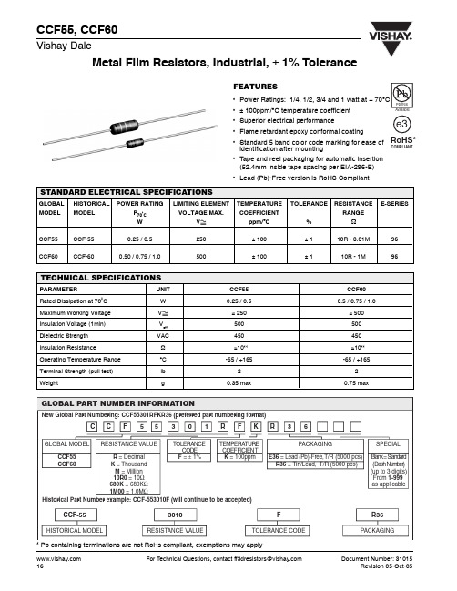
A 0.245 ± 0.020 [6.22 ± 0.51] 0.245 ± 0.020 [6.22 ± 0.51] 0.344 ± 0.031 [8.74 ± 0.79]
B 0.090 ± 0.008 [2.29 ± 0.20] 0.090 ± 0.008 [2.29 ± 0.20] 0.139 ± 0.009 [3.53 ± 0.23]
RATED POWER IN %
120
C
(Max.)
D 0.025 ± 0.002 [0.64 ± 0.05] 0.023 ± 0.002 [0.60 ± 0.05] 0.025 ± 0.002 [0.64 ± 0.05]
E 1.100 ± 0.040 [27.94 ± 1.02] 1.100 ± 0.040 [27.94 ± 1.02] 1.000 ± 0.040 [25.40 ± 1.02]
CCF-55
HISTORICAL MODEL
3010
RESISTANCE VALUE
F
TOLERANCE CODE
R36
PACKAGING
* Pb containing terminations are not RoHs compliant, exemptions may apply
16 For Technical Questions, contact ff3dresistors@ Document Number: 31015 Revision 05-Oct-05
* Test Methods per MIL-STD-202G/IEC 60115/DIN EN 140000 (as applicable).
Document Number: 31015 Revision 05-Oct-05
For Technical Questions, contact ff3dresistors@
元器件交易网
CCF55, CCF60
Metal Film Resistors, Industrial, ± 1% Tolerance
DIMENSIONS in inches [millimeters]
A E
Vishay Dale
C Max.
B
D
GLOBAL MODEL CCF55 (Sn/Pb) CCF55 (Sn) CCF60
