MPV3J80S8QJ中文资料
TeSys混合电机启动器产品说明书
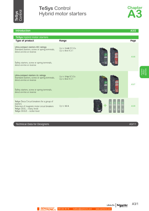
H y b r i d m o t o r s t a r t e r sTeSys ControlHybrid motor startersType of productRangePageUltra-compact starters IEC ratingsStandard starters, screw or spring terminals, direct-on-line or reverseUp to 3 kW AC53a Up to 9 A AC51A3/6Safety starters, screw or spring terminals,direct-on-line or reverseUltra-compact starters UL ratingsStandard starters, screw or spring terminals,direct-on-line or reverseUp to 3 hp AC53a Up to 9 A AC51A3/7Safety starters, screw or spring terminals,direct-on-line or reverseTeSys Deca Circuit breakers for a group of startersSelection of magnetic motor circuit breakers TeSys GV2L – rotary knob TeSys GV2LE – rocker leverUp to 32 AA3/8A3/11ChapterA3The most compact 3 KW / 400 V starterin the worldWith printed QR code, refering directly to the product data sheet.H y b r i d m o t o r s t a r t e r sStandard versionp 2 ratings:- 2.4 A 400 V AC53a - 6.5 A 400 V AC53ap 2 control voltages:- 24 V DC- 110 V / 230 V ACSafety versionp Safe T orque Off embedded:- SIL3 according to IEC61508-1 - Ple according to ISO13849-1 p ATEX:- A s associated devices for motor protectionP B 114714_r .e p sP B 114712_r .e p sP B 114718-r .e p sP B 114716_r .e p sp 2 terminal types:- Screw clamps - Springp C an provide up to3 functions:- Forward running - Reverse running - Overload protectionP B 114712_r.e psP B 114801_r .e psP B 114802_r .e p sP B 114711_r .e p sDirect-on-lineHybrid Standard starterReverseIntroductionH y b r i dm o t o r s t a r t e r sHybrid Safety starterHybrid motor starters 101393.e p s107014.e p s101393.e p s107014.e p s101393.e p s 107014.e p sP B 114847_r .e p sP B 113929_r .e p sP B 113929_r .e p s101393.e p s107014.e p sP B 114847_r .e p sP B 113929_r .e p sP B 113929_r .e p sP B 114711.e psP B 114715.e ps1.5 1.52.23333 1.5...6.5LZ8H6X5pp Spring terminals0.370.370.750.750.750.75 1.10.18...2.4LZ8H2X43pp 1.51.52.233331.5...6.5LZ8H6X53pp(1)Remplace the ●● in the reference by the bobine code: BD (24 V DC) or FU (110-230 V AC).Safety LZ7H2X4pp 9Standard LZ1H6X5pp Safety LZ7H6X5pp Spring terminals2.4Standard LZ1H2X43pp Safety LZ7H2X43pp 9Standard LZ1H6X53pp SafetyLZ7H6X53pp(1) Remplace the ●● in the reference by the bobine code: BD (24 V DC) or FU (110-230 V AC).LZ1H2X4BDLZ7H2X4BDH y b r i d m o t o r s t a r t e r sP B 114713.e psP B 114716.e ps1 1.53 1.5...6.5LZ8H6X5pp Spring terminals1/21/210.18...2.4LZ8H2X43pp 11.531.5...6.5LZ8H6X53pp(1)Remplace the ●● in the reference by the bobine code: BD (24 V DC) or FU (110-230 V AC).Safety LZ7H2X4pp 9Standard LZ1H6X5pp Safety LZ7H6X5pp Spring terminals2.4Standard LZ1H2X43pp Safety LZ7H2X43pp 9Standard LZ1H6X53pp SafetyLZ7H6X53pp(1) Remplace the ●● in the reference by the bobine code: BD (24 V DC) or FU (110-230 V AC).LZ1H2X43BDLZ8H6X5BDMagnetic motor circuit breakers:b GV2L: rotary knob type - Ue = 500 V bGV2LE: rocker lever type - Ue = 415 V.150.011GV2L05GV2LE051.650.011GV2L06GV2LE062.535.011GV2L07GV2LE07412.511GV2L08GV2LE086.38.021GV2L10GV2LE10Deca Magnetic circuit breakers for group protection P B 121671_R .e psP B 114721_r .e psP B 114721_r .e psP B 114721_r .e psP B 114721_r .e p sGV2L + LZ2H2X4BDSelection tableTeSys Control Hybrid motor startersLZ1H2X43BD LZ1H2X43FU LZ1H2X4BD LZ1H2X4FU LZ1H6X53BD LZ1H6X53FU LZ1H6X5BD LZ1H6X5FU LZ2H2X43BD LZ2H2X43FU LZ2H2X4BD LZ2H2X4FU LZ2H6X53BD LZ2H6X53FU LZ2H6X5BD LZ2H6X5FU LZ7H2X43BD LZ7H2X43FU LZ7H2X4BD LZ7H2X4FU LZ7H6X53BD LZ7H6X53FU LZ7H6X5BD LZ7H6X5FU LZ8H2X43BD LZ8H2X43FU LZ8H2X4BD LZ8H2X4FU LZ8H6X53BD LZ8H6X53FU LZ8H6X5BD LZ8H6X5FUProduct referencesAb Thermal overload: the motor currents exceed the set value.b Phase unbalanced: the motor currents differ from each other by more than 33 % b Phase loss: power missing on one or several phasesb Stall and jam: motor current exceeding 45 A for more that 2 s during starting or running phase - No motor is connected - Motor current is lower that the minimum configurable current for more than 2 seconds, on at least two phases.For all this detected situations, the Hybrid motor starter will switch off, activate its TRP/ERR LED and fault signaling contact.Please refer to the “Instruction sheet and User Guide” for more information.PreferredElectrical life time: 30000000 AC53a electrical cyclesSafety Chain Application for Monitoring Emergency STOP Circuits with Two Channel Inputs and Two Channel Outputs with Preventa XPSAF Safety Processing Device.Possible but non- recommendedElectrical life time: 10000 AC53 a electrical cyclesSafety Chain Application for Monitoring Emergency Stop Circuits with Two Channel Inputs and Two Channel Outputs with Preventa XPSAC Safety Processing Device.1, 21, 2CharacteristicsCharacteristics Hybrid motor startersTaI n (A )1020305060704006427531(°C)D B 418907.e p sDerating according:b motor starter control power supply b ambient temperature (Ta)bdistance between devices 1: 20 mm, with spacing2: without spacing.TaI n (A )1020305060704006427531(°C)D B 418908.e p sD B 418914.e p sD B 418916.ep sPower terminalsT1, T2, T3 Motor connection L1, L2, L3 Power inputsControl terminals A1, A2 Auxiliary power unit I.1Control input, direction 1 I.2C ontrol input, direction 2 (LZ2H and LZ8H only)CC ontrol inputs common point (LZ7H and LZ8H only)Y1 Reset mode, common point Y2 Reset mode, remote, manual Y3 Reset mode, automatic98, 96, 95 Trip or error signaling contactDimensions, schemesCharacteristics:。
ET80960JA3V252中文资料

80960JA/JF/JD/JS/JC/JT 3.3 V Embedded 32-Bit MicroprocessorDatasheetProduct Featuress Code Compatible with all 80960Jx ProcessorssHigh-Performance Embedded Architecture —One Instruction/Clock Execution —Core Clock Rate is:1x the Bus Clock for 80960JA/JF/JS 2x the Bus Clock for 80960JD/JC 3x the Bus Clock for 80960JT —Load/Store Programming Model —Sixteen 32-Bit Global Registers—Sixteen 32-Bit Local Registers (8 sets)—Nine Addressing Modes—User/Supervisor Protection Model sTwo-Way Set Associative Instruction Cache—80960JA - 2Kbyte —80960JF/JD - 4Kbyte —80960JS/JC/JT - 16Kbyte —Programmable Cache-Locking MechanismsDirect Mapped Data Cache —80960JA - 1Kbyte —80960JF/JD - 2Kbyte —80960JS/JC/JT - 4Kbyte —Write Through Operation sOn-Chip Stack Frame Cache—Seven Register Sets May Be Saved —Automatic Allocation on Call/Return —0-7 Frames Reserved for High-Priority InterruptssOn-Chip Data RAM—1Kbyte Critical Variable Storage —Single-Cycle Access s3.3V Supply Voltage —5V Tolerant Inputs—TTL Compatible Outputs sHigh Bandwidth Burst Bus—32-Bit Multiplexed Address/Data—Programmable Memory Configuration —Selectable 8-, 16-, 32-Bit Bus Widths —Supports Unaligned Accesses—Big or Little Endian Byte Ordering sHigh-Speed Interrupt Controller —31 Programmable Priorities —Eight Maskable Pins plus NMI#—Up to 240 Vectors in Expanded Mode sTwo On-Chip Timers—Independent 32-Bit Counting —Clock Prescaling by 1, 2, 4 or 8—Internal Interrupt Sources s Halt Mode for Low Powers IEEE 1149.1 (JTAG) Boundary Scan Compatibility sPackages—132-Lead Pin Grid Array (PGA)—132-Lead Plastic Quad Flat Pack (PQFP)—196-Ball Mini Plastic Ball Grid Array (MPBGA)Order Number: 273159-006August 2004INFORMATION IN THIS DOCUMENT IS PROVIDED IN CONNECTION WITH INTEL® PRODUCTS. NO LICENSE, EXPRESS OR IMPLIED, BY ESTOPPEL OR OTHERWISE, TO ANY INTELLECTUAL PROPERTY RIGHTS IS GRANTED BY THIS DOCUMENT. EXCEPT AS PROVIDED IN INTEL’S TERMS AND CONDITIONS OF SALE FOR SUCH PRODUCTS, INTEL ASSUMES NO LIABILITY WHATSOEVER, AND INTEL DISCLAIMS ANY EXPRESS OR IMPLIED WARRANTY, RELATING TO SALE AND/OR USE OF INTEL PRODUCTS INCLUDING LIABILITY OR WARRANTIES RELATING TO FITNESS FOR A PARTICULAR PURPOSE, MERCHANTABILITY, OR INFRINGEMENT OF ANY PATENT, COPYRIGHT OR OTHER INTELLECTUAL PROPERTY RIGHT. Intel products are not intended for use in medical, life saving, life sustaining applications.Intel may make changes to specifications and product descriptions at any time, without notice.Designers must not rely on the absence or characteristics of any features or instructions marked "reserved" or "undefined." Intel reserves these for future definition and shall have no responsibility whatsoever for conflicts or incompatibilities arising from future changes to them.The 80960JA/JF/JD/JS/JC/JT 3.3 V Embedded 32-Bit Microprocessor may contain design defects or errors known as errata which may cause the product to deviate from published specifications. Current characterized errata are available on request.Contact your local Intel sales office or your distributor to obtain the latest specifications and before placing your product order.Copies of documents which have an ordering number and are referenced in this document, or other Intel literature may be obtained by calling1-800-548-4725 or by visiting Intel’s website at .AlertVIEW, AnyPoint, AppChoice, BoardWatch, BunnyPeople, CablePort, Celeron, Chips, CT Connect, CT Media, Dialogic, DM3, EtherExpress, ETOX, FlashFile, i386, i486, i960, iCOMP, InstantIP, Intel, Intel logo, Intel386, Intel486, Intel740, IntelDX2, IntelDX4, IntelSX2, Intel Create & Share, Intel GigaBlade, Intel InBusiness, Intel Inside, Intel Inside logo, Intel NetBurst, Intel NetMerge, Intel NetStructure, Intel Play, Intel Play logo, Intel SingleDriver, Intel SpeedStep, Intel StrataFlash, Intel TeamStation, Intel Xeon, Intel XScale, IPLink, Itanium, LANDesk, LanRover, MCS, MMX, MMX logo, Optimizer logo, OverDrive, Paragon, PC Dads, PC Parents, PDCharm, Pentium, Pentium II Xeon, Pentium III Xeon, Performance at Your Command, RemoteExpress, Shiva, SmartDie, Solutions960, Sound Mark, StorageExpress, The Computer Inside., The Journey Inside, TokenExpress, Trillium, VoiceBrick, Vtune, and Xircom are trademarks or registered trademarks of Intel Corporation or its subsidiaries in the United States and other countries.*Other names and brands may be claimed as the property of others.Copyright © Intel Corporation, 2002, 2004Contents Contents1.0Introduction (7)2.080960Jx Overview (9)2.180960 Processor Core (10)2.2Burst Bus (11)2.3Timer Unit (11)2.4Priority Interrupt Controller (11)2.5Instruction Set Summary (12)2.6Faults and Debugging (12)2.7Low Power Operation (12)2.8Test Features (12)2.9Memory-Mapped Control Registers (13)2.10Data Types and Memory Addressing Modes (13)3.0Packaging Information (15)3.1Available Processors and Packages (15)3.2Pin Descriptions (16)3.2.1Functional Pin Definitions (16)3.2.280960Jx 132-Lead PGA Pinout (23)3.2.380960Jx 132-Lead PQFP Pinout (27)3.2.480960Jx 196-Ball MPBGA Pinout (30)4.0Electrical Specifications (35)4.1Absolute Maximum Ratings (35)4.2Operating Conditions (35)4.3Connection Recommendations (36)4.4VCC5 Pin Requirements (VDIFF) (36)4.5VCCPLL Pin Requirements (37)4.6 D.C. Specifications (38)4.7 A.C. Specifications (42)4.7.1 A.C. Test Conditions and Derating Curves (45)4.7.1.1Output Delay or Hold vs. Load Capacitance (46)4.7.1.2T LX vs. AD Bus Load Capacitance (47)4.7.1.3ICC Active vs. Frequency (49)4.7.2 A.C. Timing Waveforms (53)5.0Device Identification (59)5.180960JS/JC/JT Device Identification Register (60)5.280960JD Device Identification Register (61)5.380960JA/JF Device Identification Register (62)6.0Thermal Specifications (63)6.1Thermal Management Accessories (68)6.1.1Heatsinks (68)7.0Bus Functional Waveforms (69)7.1Basic Bus States (79)7.2Boundary-Scan Register (80)ContentsFigures180960Jx Microprocessor Package Options (7)280960Jx Block Diagram (10)3132-Lead Pin Grid Array Top View-Pins Facing Down (23)4132-Lead Pin Grid Array Bottom View-Pins Facing Up (24)5132-Lead PQFP - Top View (27)6196-Ball Mini Plastic Ball Grid Array Top View-Balls Facing Down (30)7196-Ball Mini Plastic Ball Grid Array Bottom View-Balls Facing Up (31)8VCC5 Current-Limiting Resistor (36)9VCCPLL Lowpass Filter (37)10 A.C. Test Load (45)11Output Delay or Hold vs. Load Capacitance–80960JS/JC/JT (3.3 V Signals) (46)12Output Delay or Hold vs. Load Capacitance–80960JS/JC/JT (5V Signals) (46)13Output Delay or Hold vs. Load Capacitance–80960JA/JF/JD (47)14T LX vs. AD Bus Load Capacitance–80960JS/JC/JT (3.3V Signals) (47)15T LX vs. AD Bus Load Capacitance–80960JS/JC/JT (5V Signals) (48)16T LX vs. AD Bus Load Capacitance–80960JA/JF/JD (48)17I CC Active (Power Supply) vs. Frequency–80960JA/JF (49)1880960JA/JF I CC Active (Thermal) vs. Frequency (49)1980960JD I CC Active (Power Supply) vs. Frequency (50)2080960JD I CC Active (Thermal) vs. Frequency (50)2180960JC I CC Active (Power Supply) vs. Frequency (51)2280960JC I CC Active (Thermal) vs. Frequency (51)2380960JS I CC Active (Power Supply) vs. Frequency (52)2480960JS I CC Active (Thermal) vs. Frequency (52)25CLKIN Waveform (53)26T OV1 Output Delay Waveform (53)27T OF Output Float Waveform (54)28T IS1 and T IH1 Input Setup and Hold Waveform (54)29T IS2 and T IH2 Input Setup and Hold Waveform (54)30T IS3 and T IH3 Input Setup and Hold Waveform (55)31T IS4 and T IH4 Input Setup and Hold Waveform (55)32T LX, T LXL and T LXA Relative Timings Waveform (56)33DT/R# and DEN# Timings Waveform (56)34TCK Waveform (57)35T BSIS1 and T BSIH1 Input Setup and Hold Waveforms (57)36T BSOV1 and T BSOF1 Output Delay and Output Float Waveform (57)37T BSOV2 and T BSOF2 Output Delay and Output Float Waveform (58)38T BSIS2 and T BSIH2 Input Setup and Hold Waveform (58)3980960JS/JC/JT Device Identification Register Fields (60)4080960JD Device Identification Register Fields (61)4180960JA/JF Device Identification Register Fields (62)42Non-Burst Read and Write Transactions Without Wait States, 32-Bit Bus (69)43Burst Read and Write Transactions Without Wait States, 32-Bit Bus (70)44Burst Write Transactions With 2,1,1,1 Wait States, 32-Bit Bus (71)45Burst Read and Write Transactions Without Wait States, 8-Bit Bus (72)46Burst Read and Write Transactions With 1, 0 Wait Statesand Extra Tr State on Read, 16-Bit Bus (73)47Double Word Read Bus Request, Misaligned One Byte FromQuad Word Boundary, 32-Bit Bus, Little Endian (74)Contents 48HOLD/HOLDA Waveform For Bus Arbitration (75)49Cold Reset Waveform (76)50Warm Reset Waveform (77)51Entering the ONCE State (78)52Bus States with Arbitration (80)53Summary of Aligned and Unaligned Accesses (32-Bit Bus) (84)54Summary of Aligned and Unaligned Accesses (32-Bit Bus) (Continued) (85)Tables180960Jx 3.3-V Microprocessor Family (7)280960Jx Instruction Set (14)380960Jx Processors Available in 132-Pin PGA Package (15)480960Jx Processors Available in 132-Pin PQFP Package (15)580960Jx Processors Available in Extended Temperature (16)680960Jx Processors Available in 196-Ball MPBGA Package (16)7Pin Description Nomenclature (17)8Pin Description—External Bus Signals (18)9Pin Description—Processor Control Signals, Test Signals, and Power (21)10Pin Description—Interrupt Unit Signals (22)11132-Lead PGA Pinout—In Signal Order (25)12132-Lead PGA Pinout—In Pin Order (26)13132-Lead PQFP Pinout—In Signal Order (28)14132-Lead PQFP Pinout—In Pin Order (29)15196-Ball MPBGA Pinout—In Signal Order (32)16196-Ball MPBGA Pinout—In Pin Order (33)17Absolute Maximum Ratings (35)1880960Jx Operating Conditions (35)19VDIFF Parameters (37)2080960Jx D.C. Characteristics (38)2180960Jx I CC Characteristics (39)2280960Jx A.C. Characteristics (42)23Note Definitions for Table 22, 80960Jx AC Characteristics (45)2480960Jx Device Type and Stepping Reference (59)2580960JS/JC/JT Device ID Register Field Definitions (60)2680960JS/JC/JT Device ID Model Types (60)2780960JD Device ID Field Definitions (61)2880960JD Device ID Model Types (61)2980960JA/JF Device ID Field Definitions (62)3080960JA/JF Device ID Model Types (62)31Thermal Resistance for q CA and q JC Reference Table (63)32Maximum Ambient Temperature Reference Table (63)33132-Lead PGA Package Thermal Characteristics (64)3480960JA/JF/JD 196-Ball MPBGA Package Thermal Characteristics (64)3580960JS/JC/JT 196-Ball MPBGA Package Thermal Characteristics (65)36132-Lead PQFP Package Thermal Characteristics (65)37Maximum T A at Various Airflows in °C (80960JT) (66)38Maximum T A at Various Airflows in °C (80960JC) (66)39Maximum T A at Various Airflows in °C (80960JD) (67)40Maximum T A at Various Airflows in °C (80960JS) (67)41Maximum T A at Various Airflows in °C (80960JA/JF) (68)Contents42Boundary-Scan Register—Bit Order (81)43Natural Boundaries for Load and Store Accesses (81)44Summary of Byte Load and Store Accesses (82)45Summary of Short Word Load and Store Accesses (82)46Summary of n-Word Load and Store Accesses (n = 1, 2, 3, 4) (83)Revision HistoryDate Revision DescriptionSeptember 2002005Removed reference to A80960JF-16 from Table 3 on page15. Removed reference to NG80960JC-40, NG80960JC-33, NG80960JS-16,and NG80960JF-16 from Table 4 on page15.Removed reference to GD80960JC-40, GD80960JC-33, and 80960JS-16 in Table 6 on page16.Removed reference to 80960JC-40, 80960JC-33, 80960JS-16, and 80960JF-16 in Table 18 on page35.Removed reference to 80960JC-40, 80960JC-33, 80960JS-16, and 80960JF-16 from Table 21 on page39.Removed reference to 80960JC-40, 80960JC-33, 80960JS-16 and 80960JF-16 from Table 22 on page42.September 1999004Added new extended temp device offerings. See Table 5 on page16. Removed PGA package availability from JS/JC/JT processors. Changed AC timing parameter T OV1 (min) for extended temp devices only.See Table 22 on page42.June 1999003Merged the 80960JS/JC datasheet information into this datasheet (previously named 80960JA/JF/JD/JT 3.3V Embedded 32-Bit Microprocessor datasheet).Updated I CC values for the 80960JS/JC/JT processors. Increased TIH1 specification for the 80960JS/JC/JT processors. Updated MPBGA thermal specifications.December 1998002Corrected orientation of MPBGA package diagrams (Figure 6 on page30 and Figure 7 on page31).Added Figure 11 on page46,Figure 12 on page46,Figure 14 on page47, and Figure 15 on page48 to distinguish 80960JT 3.3-V and 5-V signal derating curves from the 80960JA/JF/JD derating curves.March 1998001This datasheet supersedes revisions to the following 80960Jx datasheets: #273109 (JT), #272971-002 (JD), and #276146-001 (JA/JF). In addition to combining the documents into one, the following content was changed: Figure 1 on page7: Added MPBGA package to diagram.Section 3.2.4, “80960Jx 196-Ball MPBGA Pinout” on page30: Added new Figures 6 and 7, Tables 10, 11 and 13.Figure 16 on page48: Added with the note that follows the figure.August 2004006To address the fact that many of the package prefix variables have changed, all package prefix variables in this document are now indicated with an "x".80960JA/JF/JD/JS/JC/JT 3.3 V Embedded 32-Bit Microprocessor1.0IntroductionThis document contains information for the 80960Jx microprocessors, including electrical characteristics and package pinout information. Detailed functional descriptions, other than parametric performance, are published in the i960® Jx Microprocessor Developer’s Manual(272483) and may be viewed online at /design/i960/Techinfo/80960JX/.Throughout this datasheet, references to ‘80960Jx’ indicate features that apply to the 3.3-V Jx processors only:Figure 1. 80960Jx Microprocessor Package Optionsi960®iM©19xxx80960JXXXXXXXXX SS132-Pin PQFPTable 1. 80960Jx 3.3-V Microprocessor FamilyProcessor Voltage Instruction Cache Data Cache Core Clock80960JA 3.3 V (5 V Tolerant) 2 Kbyte 1 Kbyte 1x 80960JF 3.3 V (5 V Tolerant) 4 Kbyte 2 Kbyte 1x 80960JD 3.3 V (5 V Tolerant) 4 Kbyte 2 Kbyte 2x 80960JS 3.3 V (5 V Tolerant)16 Kbyte 4 Kbyte 1x 80960JC 3.3 V (5 V Tolerant)16 Kbyte 4 Kbyte 2x 80960JT3.3 V (5 V Tolerant)16 Kbyte4 Kbyte3xNOTE: To address the fact that many of the package prefix variables have changed, all package prefix variables in this document are now indicated with an "x".This page intentionally left blank.80960JA/JF/JD/JS/JC/JT 3.3 V Embedded 32-Bit Microprocessor 2.080960Jx OverviewThe 80960Jx processor offers high performance to cost-sensitive 32-bit embedded applications.The 80960Jx is object code compatible with the 80960 core architecture and is capable of sustainedexecution at the rate of one instruction per clock. This processor’s features include generousinstruction cache, data cache, and data RAM. It also boasts a fast interrupt mechanism anddual-programmable timer units.The 80960Jx processor’s clock multiplication operates the processor core at two or three times thebus clock rate to improve execution performance without increasing the complexity of boarddesigns.Memory subsystems for cost-sensitive embedded applications often impose substantial wait statepenalties. The 80960Jx integrates considerable storage resources on-chip to decouple CPUexecution from the external bus.The 80960Jx rapidly allocates and de-allocates local register sets during context switches. Theprocessor must flush a register set to the stack only when it saves more than seven sets to its localregister cache.A 32-bit multiplexed burst bus provides a high-speed interface to system memory and I/O. A fullcomplement of control signals simplifies the connection of the 80960Jx to external components.The user programs physical and logical memory attributes through memory-mapped controlregisters (MMRs), an extension not found on the i960® Kx, Sx or Cx processors. Physical andlogical configuration registers enable the processor to operate with all combinations of bus widthand data object alignment. The processor supports a homogeneous byte ordering model.This processor integrates two important peripherals: a timer unit and an interrupt controller. Theseand other hardware resources are programmed through memory-mapped control registers, anextension to the familiar i960 processor architecture.The timer unit (TU) offers two independent 32-bit timers for use as real-time system clocks andgeneral-purpose system timing. These operate in either single-shot or auto-reload mode and maygenerate interrupts.The interrupt controller unit (ICU) provides a flexible, low-latency means for requesting interrupts.The ICU provides full programmability of up to 240 interrupt sources into 31 priority levels. TheICU takes advantage of a cached priority table and optional routine caching to minimize interruptlatency. Clock doubling on the 80960JD/JC processors reduces interrupt latency by 40% comparedto the 80960JA/JF, and clock tripling on the 80960JT reduces interrupt latency by 20% comparedto the 80960JD/JC. Local registers may be dedicated to high-priority interrupts to further reducelatency. Acting independently from the core, the ICU compares the priorities of posted interruptswith the current process priority, off-loading this task from the core. The ICU also supports theintegrated timer interrupts.The 80960Jx features a Halt mode designed to support applications where low power consumptionis critical. The halt instruction shuts down instruction execution, resulting in a power savings of upto 90 percent.The 80960Jx’s testability features, including ONCE (On-Circuit Emulation) mode and BoundaryScan (JTAG), provide a powerful environment for design debug and fault diagnosis.80960JA/JF/JD/JS/JC/JT 3.3 V Embedded 32-Bit MicroprocessorThe Solutions960® program features a wide variety of development tools which support the i960 processor family. Many of these tools are developed by partner companies; some are developed by Intel, such as profile-driven optimizing compilers. For more information on these products, contact your local Intel representative.2.180960 Processor CoreThe 80960Jx family is a scalar implementation of the 80960 core architecture. Intel designed this processor core as a very high performance device that is also cost-effective. Factors that contribute to the core ’s performance include:•Core operates at the bus speed with the 80960JA/JF/JS•Core operates at two or three times the bus speed with the 80960JD/JC and 80960JT,respectively•Single-clock execution of most instructions •Independent Multiply/Divide Unit•Efficient instruction pipeline minimizes pipeline break latency•Register and resource scoreboarding allow overlapped instruction execution •128-bit register bus speeds local register caching •Two-way set associative, integrated instruction cache •Direct-mapped, integrated data cache•1-Kbyte integrated data RAM delivers zero wait state program dataFigure 2. 80960Jx Block DiagramProgrammable Interrupt Controller Control Address/Instruction SequencerPhysical Region Configuration Interrupt Port1K Data RAMMemory Interface Execution Multiply UnitDivide UnitMemory-Mapped Register InterfaceData BusGlobal / Local Register FileSRC2DESTSRC1addressControleffective ConstantsGenerationUnitAddress 32-bit Address 32-bit DataBus Request Queuesand Two 32-BitTimers8-SetLocal Register CacheS R C 1S R C 2D E S TPLL, Clocks,Power MgmtBoundary Scan ControllerTAP 5CLKINS R C 1S R C 2D E S TS R C 1D E S T93232-bit buses address / data21Instruction Cache 80960JA - 2K 80960JF/JD - 4K80960JS/JC/JT - 16KDirect Mapped Data Cache 80960JA - 1K 80960JF/JD - 2K 80960JS/JC/JT -1283 Independent 32-Bit SRC1, SRC2, and DEST BusesBus Control Unit80960JA/JF/JD/JS/JC/JT 3.3 V Embedded 32-Bit Microprocessor2.2Burst BusA 32-bit high-performance Bus Controller Unit (BCU) interfaces the 80960Jx to external memoryand peripherals. The BCU fetches instructions and transfers data at the rate of up to four 32-bitwords per six clock cycles. The external address/data bus is multiplexed.Users may configure the 80960Jx’s bus controller to match an application’s fundamental memoryorganization. Physical bus width is register-programmed for up to eight regions. Byte ordering anddata caching are programmed through a group of logical memory templates and a defaults register.The BCU’s features include:•Multiplexed external bus to minimize pin count•32-, 16-, and 8-bit bus widths to simplify I/O interfaces•External ready control for address-to-data, data-to-data and data-to-next-address wait state types•Support for big or little endian byte ordering to facilitate the porting of existing program code•Unaligned bus accesses performed transparently•Three-deep load/store queue to decouple the bus from the coreUpon reset, the 80960Jx conducts an internal self-test. Then, before executing its first instruction, itperforms an external bus confidence test by performing a checksum on the first words of theinitialization boot record (IBR).2.3Timer UnitThe timer unit (TU) contains two independent 32-bit timers that are capable of counting at severalclock rates and generating interrupts. Each is programmed by use of the TU registers. Thesememory-mapped registers are addressable on 32-bit boundaries. The timers have a single-shotmode and auto-reload capabilities for continuous operation. Each timer has an independentinterrupt request to the 80960Jx’s interrupt controller. The TU may generate a fault whenunauthorized writes from user mode are detected. Clock prescaling is supported.2.4Priority Interrupt ControllerA programmable interrupt controller manages up to 240 external sources through an 8-bit externalinterrupt port. Alternatively, the interrupt inputs may be configured for individual edge- or level-triggered inputs. The interrupt unit (IU) also accepts interrupts from the two on-chip timer channelsand a single Non-Maskable Interrupt (NMI#) pin. Interrupts are serviced according to their prioritylevels relative to the current process priority.Low interrupt latency is critical to many embedded applications. As part of its highly flexibleinterrupt mechanism, the 80960Jx exploits several techniques to minimize latency:•Interrupt vectors and interrupt handler routines may be reserved on-chip.•Register frames for high-priority interrupt handlers may be cached on-chip.•The interrupt stack may be placed in cacheable memory space.•Interrupt microcode executes at two or three times the bus frequency for the 80960JD/JC and 80960JT, respectively.80960JA/JF/JD/JS/JC/JT 3.3 V Embedded 32-Bit Microprocessor2.5Instruction Set SummaryThe 80960Jx adds several new instructions to the i960 processor core architecture. The newinstructions are:•Conditional Move•Conditional Add•Conditional Subtract•Byte Swap•Halt•Cache Control•Interrupt ControlTable 2 identifies the instructions that the 80960Jx supports. Refer to the i960® Jx MicroprocessorDeveloper’s Manual (272483) for a detailed description of each instruction.2.6Faults and DebuggingThe 80960Jx employs a comprehensive fault model. The processor responds to faults by makingimplicit calls to a fault handling routine. Specific information collected for each fault allows thefault handler to diagnose exceptions and recover appropriately.The processor also has built-in debug capabilities. In software, the 80960Jx may be configured todetect as many as seven different trace event types. Alternatively, mark and fmark instructionsmay generate trace events explicitly in the instruction stream. Hardware breakpoint registers arealso available to trap on execution and data addresses.2.7Low Power OperationIntel fabricates the 80960Jx using an advanced sub-micron manufacturing process. The processor’ssub-micron topology provides the circuit density for optimal cache size and high operating speedswhile dissipating modest power. The processor also uses dynamic power management to turn offclocks to unused circuits.Users may program the 80960Jx to enter Halt mode for maximum power savings. In Halt mode,the processor core stops completely while the integrated peripherals continue to function, reducingoverall power requirements up to 90 percent. Processor execution resumes from internally orexternally generated interrupts.2.8Test FeaturesThe 80960Jx incorporates numerous features that enhance the user’s ability to test both theprocessor and the system to which it is attached. These features include ONCE (On-CircuitEmulation) mode and Boundary Scan (JTAG).80960JA/JF/JD/JS/JC/JT 3.3 V Embedded 32-Bit Microprocessor The 80960Jx provides testability features compatible with IEEE Standard Test Access Port andBoundary Scan Architecture (IEEE Std. 1149.1).One of the boundary scan instructions, HIGHZ, forces the processor to float all its output pins(ONCE mode). ONCE mode may also be initiated at reset without using the boundary scanmechanism.ONCE mode is useful for board-level testing. This feature allows a mounted 80960Jx toelectrically “remove” itself from a circuit board. This allows for system-level testing in which aremote tester, such as an in-circuit emulator, may exercise the processor system.The provided test logic does not interfere with component or circuit board behavior and ensuresthat components function correctly, connections between various components are correct, andvarious components interact correctly on the printed circuit board.The JTAG Boundary Scan feature is an attractive alternative to conventional “bed-of-nails” testing.It may examine connections that might otherwise be inaccessible to a test system.2.9Memory-Mapped Control RegistersThe 80960Jx, although compliant with the i960 processor core, has the added advantage ofmemory-mapped, internal control registers not found on the i960 Kx, Sx or Cx processors. Theseregisters give software the interface to easily read and modify internal control registers.Each of these registers is accessed as a memory-mapped, 32-bit register. Access is accomplishedthrough regular memory-format instructions. The processor ensures that these accesses do notgenerate external bus cycles.2.10Data Types and Memory Addressing ModesAs with all i960 processors, the 80960Jx instruction set supports several data types and formats:•Bit•Bit fields•Integer (8-, 16-, 32-, 64-bit)•Ordinal (8-, 16-, 32-, 64-bit unsigned integers)•Triple word (96 bits)•Quad word (128 bits)The 80960Jx provides a full set of addressing modes for C and assembly programming:•Two Absolute modes•Five Register Indirect modes•Index with displacement•IP with displacement。
QJ系列潜水泵主要技术参数
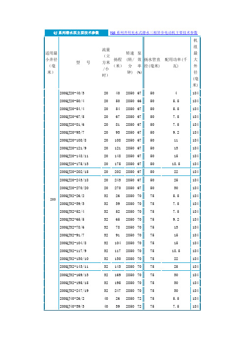
200QJ系列潜水泵主要技术参数表150QJ系列潜水泵主要技术参数表175QJ系列潜水泵主要技术参数表250QJ系列潜水泵主要技术参数表250---机座号QJ---潜水泵10----流量-34------杨程300QJ系列潜水泵主要技术参数表400QJ系列潜水泵主要技术参数表常用水泵型号代号DL------多级立式清水泵BX-------消防固定专用水泵ISG------单级立式管道泵IS -------单级卧式清水泵DA1-------多级卧式清水泵QJ-------潜水泵泵型号意义:如40LG12-15 40-进出口直径(mm)LG-高层建筑给水泵(高速)12-流量(m3/h)15-单级扬程(M)200QJ20-108/8 200---表示机座号200QJ---潜水电泵20—流量20m3/h 108---扬程108M8---级数8级水泵的基本构成:电机、联轴器、泵头(体)及机座(卧式)。
水泵的主要参数有:流量,用Q表示,单位是M3/H ,L/S。
扬程,用H表示,单位是M。
对清水泵,必需汽蚀余量(M)参数非常重要,特别是用于吸上式供水设备时。
对潜水泵,额定电流参数(A)非常重要,特别是用于变频供水设备时。
电机的主要参数:电机功率(KW),转速(r/min),额定电压(V),额定电流(A)水泵型号代表水泵的构造特点工作性能和被输送介质的性质等。
由于水泵的品种繁多,规格不一,所以型号也较紊乱,这里只列出一些常见的水泵型号。
BA型泵单级单吸悬臂式离心泵,流量为4.5~360米³/时,扬程为8~98米,介质温度在80℃以下。
以8BA——18A为例:8——代表吸入管接头为8英寸;BA——代表单级单吸悬臂式离心泵;18——代表缩小1/10后化为整数的比转数;A——代表缩小了外径的叶轮。
SH型泵单级双吸泵壳水平中开的卧式离心泵,流量为102~12500米³/时,扬程为9~140米,介质温度小于80℃。
三晶变频器说明书SAJ8000系列简约版
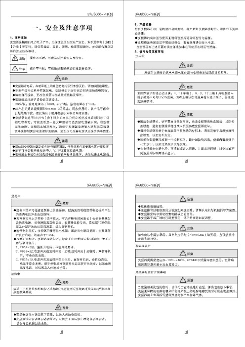
二、配线变频器配线部分,分为主回路和控制回路。
用户可将外壳的盖子掀开,此时可看到主回路端子和回路端子,用户必须依照下列的配线回路准确连接。
备注:(1)如果只有DCM端子,则ACM端子等效于DCM端子。
(2)AM端子等效于FM端子(AM为可选端子)。
三、操作及运行1、操作说明(1)键盘说明(2)状态提示灯功能☐Hz:当LED显示内容为频率数据时,该指示灯亮。
☐I:当LED显示内容为电流数据时,该指示灯亮。
☐FWD:当变频器处于正转运行时,该指示灯亮。
☐REV:当变频器处于反转运行时,该指示灯亮。
(3)监视运行参数变频器在运行过程中,按一次“DA TA”键,再按“▲”或“▼”键选择观看运行电流或运行频率。
Hz灯亮表示频率,I灯亮表示电流。
(4)查看故障记录变频器在运行过程中或待机状态下,按两次“PRGM”键,再按“▲”或“▼”键可逐次观看最近4次故障记录。
观看完后按“DATA”键,变频器复位。
(5)参数修改步骤变频器在待机状态下:步骤1:按“PRGM”键,变频器显示“Fxxx”,“xxx”为参数号。
步骤2:按“▲”或“▼”键选择所需要参数码,按“STOP/RESET”键可移动光标位置。
步骤3:按“RD/WT”键读取该参数的内容。
步骤4:按“▲”或“▼”键修改该参数值,按“STOP/RESET”键可以移动光标位置。
步骤5:按“RD/WT”键把数值设定。
如欲修改其它参数,请重复步骤1~5即可。
备注:要修改RE/WT类型的参数时必须先把F096设为“1”。
2、操作范例(1)修改参数(将F002的参数值从10S改为5S)。
变频器通电后,键盘显示“0.00”,按一次“PRGM”键,键盘显示“F000”;按“▲”键调到“F002”,按一次“RD/WT”键,读出该参数内容,键盘显示“10.0”,按“▼”键把“10”改为“5”,在按一次“ED/WT”键设定,然后按“DATA”键即可。
(2)变频器参数初始化变频器通电后,键盘显示“0.00”,按一次“PRGM”键,键盘显示“F000”,然后按“▲”键把“F000”调到“F094”,再按一次“RD/WT”键,键盘显示“0”,按“▲”键改为“1”,按“RD/WT”键设定,再按两次“PRGM”键,键盘显示“0.--”,然后在按一次“STOP/RESET”键,变频器开始初始化。
SM8JZ47中文资料

Gate Non−Trigger Voltage
Holding Current
Thermal Resistance
Critical Rate of Rise of Off−State Voltage
SM8GZ47 SM8JZ47
SM8GZ47A SM8JZ47A
Critical Rate of Rise of Off−State Voltage at Commutation
SM8GZ47,SM8JZ47,SM8GZ47A,SM8JZ47A
TOSHIBA BI−DIRECTIONAL TRIODE THYRISTOR SILICON PLANAR TYPE
SM8GZ47,SM8JZ47,SM8GZ47A,SM8JZ47A
AC POWER CONTROL APPLICATIONS
SYMBOL
TOSHIBA PRODUCT MARK
SM8GZ47, SM8GZ47A
TYPE
SM8JZ47, SM8JZ47A
SM8GZ47A, SM8JZ47A
*4
MARK
M8GZ47 M8JZ47
A
Example 8A : January 1998 8B : Febrary 1998 8L : December 1998
· The information contained herein is presented only as a guide for the applications of our products. No responsibility is assumed by TOSHIBA CORPORATION for any infringements of intellectual property or other rights of the third parties which may result from its use. No license is granted by implication or otherwise under any intellectual property or other rights of TOSHIBA CORPORATION or others.
QJ008
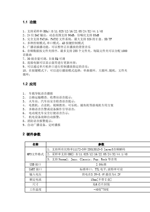
1.1 功能1、支持采样率(KHz):8/11.025/12/16/22.05/24/32/44.1/482、24位DAC输出,动态范围支持90dB,信噪比支持85dB3、完全支持FAT16、FAT32文件系统,最大支持32G的U盘、SD/TF4、多种控制模式,串口模式、AD按键控制模式5、广播语插播功能,可以暂停正在播放的背景音乐6、音频数据按文件夹排序,最多支持255个文件夹,每隔文件夹可以分配1000首歌曲7、30级音量可调,5级EQ可调8、连接电脑可以显示盘符进行更新内容;9、可以通过单片机串口进行控制播放指定的音乐;10、在按键模式下,可以进行播放模式选择:单曲循环,大循环,随机,文件夹循环;1.2 应用1、车载导航语音播报2、公路运输稽查、收费站语音提示;3、火车站、汽车站安全检查语音提示;4、电教机、点读机、视频教育、可乐机、捕鱼机等游戏机专用方案5、多路语音告警或设备操作引导语音;6、电动观光车安全行驶语音告示;7、机电设备故障自动报警;8、消防语音报警提示;9、自动广播设备,定时播报2 硬件参数名称参数MP3文件格式1、支持所有比特率11172-3和ISO13813-3 layer3音频解码2、采样率支持(KHZ):8/11.025/12/16/22.05/24/32/44.1/483、支持Normal、Jazz、Classic、Pop、Rock等音效USB接口 2.0标准UART接口标准串口,TTL电平,波特率可设输入电压供电在3.3V-5.4V最佳为4.2V 额定电流15ma[不带U盘] 尺寸见6.芯片封装工作温度-40度~70度湿度5% ~ 95%3.芯片管脚管脚号管脚名称类型功能描述1 P01 IO FLASH/TF数据脚2 P00 IO FLASH/TF 时钟脚3 P02 IO FLASH/TF 片选脚4 VCOMO I ADKEY按键值检测脚5 USBDM IO USB数据线DM6 USBDP IO USB数据线DP7 VCOM 芯片基准电压检测脚8 DACVSS AGND 模拟地9 DACR AO 芯片音源右声道输出10 DACL AO 芯片音源左声道输出11 VDDIO POWER 芯片LDO输出3.3V12 LDO5V POWER 芯片电源输入引脚5V13 VSSIO DGND 数字地14 P23/24 IO 芯片串口通信发射口TXD15 P30/P25 IO 芯片串口通信接收口RXD16 P46/VPP I 芯片工作状态指示灯,播放时输出高电平4.串口通讯协议串口作为一种在控制领域常用的通信,我们进行了工业级别的优化,加入的帧的校验、重发、错误处理等措施,大大加强通信的稳定性和可靠性,同时可以在此基础上扩展更加强大的RS485进行组网功能,串口的通信波特率可自行设置,默认为9600 可修改为19200115200等4.1 通讯格式支持异步串口通讯模式,通过串口接受上位机发送的命令通讯标准:9600 bps数据位 :1校验位 :none流控制 :none格式:$S Len CMD para1 para2 $O$S 起始位0x7E 每条命令反馈均以$开头,即0x7ELen len后字节个数Len + CMD + para1 + para2CMD 命令字表示具体的操作,比如播放/暂停等等para1 参数1 查询的数据高字节(比如歌曲序号)para2 参数2 查询的数据低字节$O 结束位结束位0xEF例如,如果我们指定播放,就需要发送:7E 04 41 00 01 EF数据长度为4 ,这4个字节分别是[04 41 00 01] 。
SSQ8中文资料
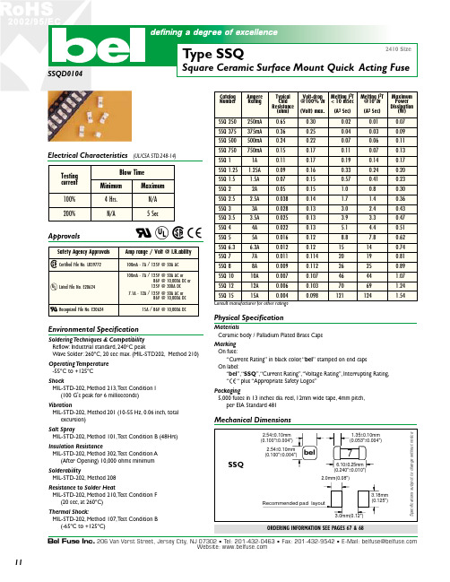
Bel Fuse Inc. 206 Van Vorst Street, Jersey City, NJ 07302 • Tel: 201-432-0463 • Fax: 201-432-9542 • E-Mail: belfuse@Website: Environmental SpecificationSoldering Techniques & Compatibility Reflow: Industrial standard, 240°C peakWave Solder: 260ºC, 20 sec max. (MIL-STD202, Method 210)Operati ng T emperature -55ºC to +125ºCShockMIL-STD-202, Method 213, T est Condition I (100 G's peak for 6 milliseconds)VibrationMIL-STD-202, Method 201 (10-55 Hz, 0.06 inch, total excursion)Salt SprayMIL-STD-202, Method 101, T est Condition B (48Hrs)Insulation ResistanceMIL-STD-202, Method 302, T est Condition A (After Opening) 10,000 ohms minimum SolderabilityMIL-STD-202, Method 208Resistance to Solder HeatMIL-STD-202, Method 210, T est Condition F (20 sec, at 260ºC)Thermal Shock:MIL-STD-202, Method 107, T est Condition B (-65ºC to +125ºC)MaterialsCeramic body / Palladium Plated Brass CapsMarking On fuse:“Current Rating” in black color, “bel ” stamped on end caps On label:“bel ”, “SSQ ”, “Current Rating”, “Voltage Rating”, Interrupting Rating,“c “ plus “Appropriate Safety Logos”Packaging5,000 fuses in 13 inches dia. reel, 12mm wide tape, 4mm pitch,per EIA Standard 481Mechanical Dimensions11T I M E I N S E C O N D SCURRENT IN AMPERESS p e c i f i c a t i o n s s u b j e c t t o c h a n g e w i t h o u t n o t i c eNOTE - see important information under “User Guide”on P.08Corporate Office Bel Fuse Inc.206 Van Vorst Street, Jersey City, NJ 07302Tel: 201-432-0463Fax: 201-432-9542E-Mail: belfuse@ Website: Far East Office Bel Fuse Ltd.8F/8 Luk Hop Street San Po KongKowloon, Hong Kong Tel: 852-2328-5515Fax: 852-2352-3706European OfficeBel Fuse Europe Ltd.Preston Technology Management Centre Marsh Lane, Preston PR1 8UD Lancashire, U.KTel: 44-1772-556601Fax: 44-1772-888366SSQ - TIME CURRENT CHARACTERISTIC CURVE- 250m A - 375m A - 500m A - 750m A - 1A - 1.25A - 1.5A - 2A - 2.5A - 3A - 3.5A - 4A - 5A - 6.3A - 7A - 8A - 10A - 12A - 15A1000010001001010.10.0111001000100.112。
Juice Goose JG 8 Series 电源分配器说明书

JUICE GOOSE7320 Ashcroft, Suite 104Houston, Texas 77081p: 713-772-1404f: 713-772-7360 OWNERS MANUAL06-04SAFETY PRECAUTIONSThe JG 8 Series products (JG8) are designed to operate with 120VAC, 60 Hz. Operation with 220 or 240 volts will cause damage and possibly cause personal injury.CAUTIONS1. The JG8 must be grounded. Defeating the unit’s grounding capability could create a hazard.2. There are no user serviceable parts inside. Do not attempt service yourself. Contact Juice Goose as directed in this manual if service is required.3. Do not expose the JG8 to moisture. Avoid severe physical impacts to the unit. DISCLAIMERJuice Goose shall under no circumstances be held responsible for any loss, damage or in-jury resulting from the use of the JG8 in a manner inconsistent with any of the procedures outlined in this document. The user is responsible for determining whether this product is appropriate for the intended application.Juice Goose is not responsible for any indirect, secondary or ancillary loss or damage, in-cluding personal injury, loss of or damage to property or loss of income resulting from the operation or failure of this unit.FRONT PANELLighted Power On/Off Switch – This switch controls power to all 8 outlets on the back of the chassis.Light Tubes (JG8.0L and JG8.0LM) - The JG 8.0L and 8.0LM feature two pull out dimmable lights that can be rotated to control the intensity and direction of the two light beams. Af-ter use, the lights slide inside the chassis to store conveniently away. These devices use 7 watt "night light" style bulbs which install from the front of each light tube assembly. To replace bulbs, unscrew front tube cap and rotate bulb counter clockwise.Voltage Meter (JG8.0LM) - The JG8.0-LM includes a 20 segment Voltage Meter that indi-cates levels of incoming AC voltage. This color coded meter displays safe (green), mar-ginal (yellow) and dangerous (red) levels of incoming voltage. This meter can help diag-nose problems that result from common AC power sags and swells.REAR PANELAC Outlets – These 8 outlets (NEMA 5-15R) are rated for current loads up to 15 amps at 120 volts.Power Cord – The power cord has a third pin safety ground connector. Do not defeat this feature. Doing so could subject user to a hazardous condition.INTERNAL PROTECTION COMPONENTSThe JG8 Series products have a Basic Level of AC power protection consisting of fast acting metal oxide varistors between hot, neutral and ground. The JGJr also features a line capacitor between hot and neutral to reduce high frequency line noise and AC line surges.TROUBLE SHOOTINGThe JG8 is well designed and constructed. Every JG8 is submitted to a full functional test be-fore being shipped by Juice Goose. It requires neither maintenance nor adjustment. It is un-likely to malfunction. However, there are potential events to note:The JG8 will not come on or turns itself off.a. Check the status of the power supplied to the unit. Use a voltage meter and/or polarity tester to examine the status of incoming power.b. Check that the circuit breaker is not tripped and that the current load on the unit does not exceed its rated 15 amp capacity. If the breaker is tripped, remove sufficient current load to reduce the total to no more than 15 amps, wait approximately 30 seconds after the trip-ping. Turn the power switch/circuit breaker back on.One or both lights will not come on (JG8.0L and JG8.0LM). – Unplug power to the JG8. Un-screw the cap on the end of the tube(s). Remove the bulb(s) in question. Take care. If the bulb is broken use a cloth or needle nose pliers to remove the component. The replacement bulb is a 7 watt, candelabra base (e.g. night light bulb).If an observed problem can not be remedied, particularly if the problem seems severe or dan-gerous, discontinue use of the JG8 and contact Juice Goose directly.REPAIRShould your product need service contact Juice Goose for assistance and authorization to return the unit. PLEASE NOTE: a return authorization number is required in order for the service personnel to correctly and promptly identify, repair and return your unit.You may obtain a Return Authorization Number by calling: 713-772-1404 or sending email to *******************.OTHER HIGH QUALITY PRODUCTS FROMJG SERIES – Rack mountable power distribution in a 19” configuration. Five models to choose from. Feature options include rack lighting and voltage meter. The JG11-20A has a 20 amp capacity, 2 unswitched outlets and a 15 foot power cord. All units contain a basic level of power conditioning.RP SERIES – Professional grade rack mountable power distribution. The 19” rack mount-able Tour Class (TM) chassis is a uni-body construction of extra sturdiness. The RP100 has 11 outlets across the back. The RP200 includes two slide out rack lights and a voltage meter. The RP200-L includes a connector for a work light on the back of the chassis. All RP Series models include enhanced components for EMI filtration in addition to voltage spike protec-tion across hot, neutral and ground leads.PD SERIES – Custom configured power strips with up to 12 circuits per unit. The PD1A, PD1B and PD3 offer various options regarding size, number and arrangement of circuits, length and location of wire harness and mounting configuration. Select exact configuration with a features menu.CQ SERIES – Power sequencing and remote control products. No master controller is required. Very flexible, economical and easy to install. Models include rack mount, four cir-cuit and 30 amp designs. Optional remote controls include key or rotary switch and secure 12 position keypad.RX SERIES – High voltage surge protection and high frequency line filtration, perform-ance near that of an isolation transformer, but at a fraction of the cost and size. Great normal mode and common mode line noise elimination. Individual products include the RX15-PWG, RX15-DPC, RX10-SCS and RP100-RX.FE SERIES – The highest quality power conditioning available, isolation + regulation transformers provide safe and stable power with a long service life. Models are available for plug-in and hard wired applications in a wide range of sizes and voltages. FE Series trans-formers maintain a constant output voltage when incoming voltage swings +10% or – 20%. UPS MODELS – When protection against power outage is needed, Juice Goose is a valuable resource. Juice Goose has manufactured and supplied power conditioning and dis-tribution products since 1983 and provides consulting and distribution service for our cus-tomers needing a UPS from APC, Liebert or PowerWare. Call Juice Goose to discuss the best technology, size and configuration for a particular application.。
SAJ8000instructionmanual英文说明书
INSTRUCTION MANUALGuangzhou Sanjing Electric CO., LTD.ADD: No.17, XiangShan Road, High and New Technology Industry Development Zone, Guangzhou , China P. C.: 510663TEL:(00)86-20-22321757 22321788 FAX: (00)86-20-22321789 22321790 E-mail:sajbp@Thanks for your buying SAJ-8000 series frequency inverter. Upon receipt of the product and prior to initial operation, read these instructions thoroughly, and retain for future reference.TABLE OF CONTENTSNOTES FOR SAFE OPERATION 1. SELECT THE RIGHT TYPE1.1 Specifications Form 1.2 Rated Output Current Form 1.3 Description of Nameplate 1 8 8 10 11 12 12 12 13 14 15 16 16 16 18TABLE OF CONTENTS3.5.4 Grounding 3.5.5 Specifications Form of Breaker, Cable and Contactor 3.5.6 Specifications Form of Braking Resistor25 26 27 28 28 28 29 29 29 30 31 31 32 32 32 32 33 34 35 36 36 434. OPERATION4.1 Keypad Description4.1.1 Keypad Schematic Diagram 4.1.2 Indicator Light Description 4.1.3 Key Function Description under Different Mode4.1.3.1 Control Mode 4.1.3.2 Monitor Mode 4.1.3.3 Parameter Modification Mode 4.1.3.4 Fault Display Mode2. INSTALLATION2.1 Storage 2.2 Installation Environment Requirements 2.3 Installation Space and Situation3. WIRING3.1 Main Circuit Wiring 3.2 Terminal Indication3.2.1 Main Circuit Terminals 3.2.2 Control Circuit Terminals 3.2.3 Control Circuit Terminals Functions and Specifications4.1.4 Keypad Operation Example4.2 Quick Start Operation Instruction4.2.1 Reset 4.2.2 Set Motor Parameters before Starting the Inverter 4.2.3 Motor Parameter Autotuning3.3 Jumper on Control Board 3.4 Wiring Diagram 3.5 Wiring the Circuit3.5.1 Wiring at Input Side of Main circuit 3.5.2 Wiring Precautions for Main Circuit Output 3.5.3 Wiring Precautions for Control Circuit20 22 23 23 24 244.2.4 Inspect the Input Main Circuit 4.2.5 Keypad Operation Flow Chart5. DETAILED FUNCTION DESCRIPTION5.1 Function Code Table 5.2 Detailed Description for Parameters of Function CodeTABLE OF CONTENTS5.3 F040 Frequency Setting Method5.3.1 F040 Frequency Setting Method Table 5.3.2 F040 Frequency Setting DescriptionsTABLE OF CONTENTS72 72 74 89 89 89 93 104 104 104 107 114 114 114 114 119 119APPEXDIX A~APPENDIX E: INVERTER CASE AND KEYBOARD SPECIFICATION6.1.2 Function Code of Modbus Supported by Inverter 6.1.3 Command Based on Modbus Protocol 6.1.4 Address Mapping 6.1.5 Modbus Communication Format 6.1.6 RS485 Hardware Interface Specification120 120 121 122 123 124 124 125 125 126 126 127 128 128 1295.4 Multi-function Digital Input Terminal Setting5.4.1 Function Code Corresponding to Multi-function Digital Input Terminal 5.4.2 Multi-function Digital Input Terminal Setting Table 5.4.3 MIn Setting Value Description6.2 PID Function Descriptions6.2.1 F073 PID Input Selection 6.2.2 PID Digital Input Selection 6.2.3 PID Output Source Selection 6.2.4 PID Analog Output Function 6.2.5 Simple PID Application 6.2.6 PID Structure Diagram5.5 Digital Output Terminal Setting5.5.1 Function Code Corresponding to Digital Output Terminal 5.5.2 Digital Output Terminal Function Setting Table 5.5.3 Descriptions7. TROUBLE SHOOTING7.1 Inverter Malfunction Code Table 7.2 Abnormal Occurrence Table5.6 Simple PLC Autorun Function5.6.1 Simple PLC Autorun Selection Table 5.6.2 Simple PLC Function Descriptions Set by F072 Table 5.6.3 Simple PLC Function Descriptions6. RS485 AND PID FUNCTION6.1 RS485 Modbus (RTU) Serial Communication Description6.1.1 Parameter Setting of Communication Port under Modbus Protocol119Read this instruction manual thoroughly before installation, operation, maintenance or inspection of the frequency inverters. In this manual, safeoperation are classified as "WARNING" or "CAUTION".Indicate a potentially dangerous situation which, if not avoided, could result in death or serious injury to personnel.!Indicate a potentially dangerous situation which, if not avoided, could result in minor or moderate injury and damage to equipment. Itmay also be used for warning against unsafe practices.Even items described as!may result in a vital accident insome situations. Please follow these important notes: These are steps to be taken to ensure proper operation.!!!!!!!!!ItemControl Signal Analog Input Analog Output Digital Input Digital OutputSpecification0~5V or 10V, 0~20mA (Z type: 0~1A, 0~5V or 10V) PWM signal output after filtering, pulse output up to 10V by setting Six group of input terminals covering 99 functions for choice Two group of programmable open-loop output and one group of programmable relay output covering 93 functions for choice.ItemInverter Capacity Range International Protection (IP) Class Cooling Method Basic Functions IP20Specification0.4KW ~750KW Forced air cooling, natural cooling Speed tracing, PID control, auto speed compensation, AVR, torque control, overlay control, time control multi-speed choice, etc.Power SupplyOutput CharacteristicsRated Input Voltage and Frequency Allowable Voltage Fluctuation Allowable Frequency Fluctuation Output Voltage Rated Output FrequencySingle phase: 220V; 3-phase:380V/460V/660V; 50/60Hz 20% 5% 3-phase:220V/380V/460V/660V (Proportional to input voltage) Up to 650 Hz available by programming From 2.5A to 920A, according to different application 1. Vector Control 2. V/F Control 3. Constant Torque or Power Control Digital command: 0.01% (controlled by the keyboard of the inverter) Analog command: 0.1% Digital operator reference: 0.01Hz Analog reference: 0.1Hz Standard accessory inside for inverter capacity: 15KW and below Optional accessory for inverter capacity: 18.5KW and over 0.0 to 6553 second (Accel/Decel time setting independently) Adjustable range: 5%~30% Allowable brake range: 0.5~50Hz Adjustable range: 0.0~25.0 second 0~6% under lower frequencyCommunication RS-485 Interface Control the motor up to 99 units by one inverter Interface Display Output current, input / output power capacity, power factor / coefficient, time, etc. Function Environment Ambient Temperature -10 ~50 (keep out of direct sunlight) Humidity Location Elevation Vibration 90% RH or less Indoor (protected from corrosive gases and dust) 1000m or less 0.5G or lessControl CharacteristicsRated Output Current Control Method Frequency AccuracyFrequency ResolutionBrake Unit (accessory)Acceleration/Deceleration time of DC Braking Braking Voltage Braking Frequency Braking Time Torque CompensationProtective FunctionsWiring Distance Between Inverter Less than 50 meters (must add reactor when over 50m ) and Motor Overload Capacity G/Z/Y/M/S type: 150% of rated output current for 1 minute Instantaneous Overcurrent F/P type: 120% of rated output current for 1 minute G/Z/Y/M/S type: Motor coasts to a stop at approx. 200% of rated output current. F/P type: Motor coasts to a stop at approx. 150% of rated output current. Protected by thermistor and motor coasts to a stop when temperature rises to 8 Short circuit, undervoltage, overvoltage, lack of phaseHeatsink Overheat OthersSingle Phase Inverter Rated 220V Output Capacity Rated Output (KW) Current (Amp)0.4 0.75 1.5 2.2 4 5.5 7.5 11 15 18.5 22 30 37 45 55 75 93 110 132 160 187 200 220 250 280 315 355 400 500 2.5 4 7 10 16 20 30 42 553-Phase 220V(240V) Rated Output Current (Amp)2.5 4 7 10 16 20 30 42 55 70 80 110 130 160 200 260 320 380 420 550 600 660 720 2.5 3.7 5 9 13 16 25 32 38 45 60 75 90 110 150 170 210 250 300 340 380 415 470 520 600 640 750 920 2.5 3.7 5 8 11 15 22 27 34 40 55 65 80 100 130 147 180 216 259 300 328 358 400 449 516 570 650 800Type of Frequency Inverter (G is General Type) Power Capacity of Frequency Inverter (018R5 is 18.5KW) Series Number (V is 8000 series)380V (415V) Rated Output Current (Amp)380V (440V) Rated Output Current (Amp)Type:Braking Unit Serial Number of ProductionVoltage Class (3 is 3-phase/380V, 2 is 3-phase/220V, 1 is single phase/220V)!In order to maintain conveniently, make sure there is plenty of space for inverter. In order to keep good cooling effect, install the inverter uprightly and keep well ventilated. If it is difficult to fasten the inverter, put a plat plate under the bottom of it. Otherwise the stress caused by getting-loose may cause damage to the main circuit components. Use nonflammable material like iron plate on the side wall of I installation. If there are multiple inverters installed in the same cabinet, keep the distance between them and add air deflector to ventilate the space.!。
AVS08中文资料
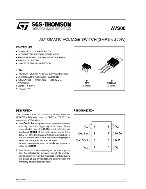
AUTOMATIC VOLTAGE SWITCH(SMPS<200W)CONTROLLER50/60Hz FULL COMPATIBILITYINTEGRATED VOLTAGE REGULATORTRIGGERING PULSE TRAIN OF THE TRIACPARASITIC FILTERLOW POWER CONSUMPTIONTRIACHIGH EFFICIENCY AND SAFETY SWITCHINGUNINSULATED PACKAGE:AVS08CBINSULATED PACKAGE2500V(RMS): AVS08CBIV DRM=±500VI T(RMS):5ADESCRIPTIONThe AVS08kit is an automatic mains selector (110/220V AC)to be used in SMPS<200W.It is composed of2devices:•The Controller is optimized for low consumption and high security triggering of the triac.When connected to V SS,the mode input activates an additional option.If the main power drops from 220V to110V,the triac control remains locked to the220V mode and avoids any high voltage spike when the voltage is restored to220V.When connected to V DD,the mode input desacti-vates this option.•The TRIAC is specially designed for this applica-tion.An optimization between sensitivity and dy-namic parameters of the triac gate highly reduces the losses of supply resistor and allows excellent immunity against disturbances.PDIP8(Plastic)BTO220AB(Plastic)A1A2GAVS08March1995PIN CONNECTION1/7ABSOLUTE MAXIMUM RATINGS CONTROLLER AVS1BCP08(1)Gate supply :I G =100mA –di/dt =1A /µs (2)T j =125°CSymbol ParameterValueUnitMin.Max.V SS Supply voltage -120.5V V I /V O I /O voltage V SS -0.50.5V I I /I O I /O current-40+40mA T stg Storage Temperature -60+150°C T operOperating Temperature code”C ”0+70°C TRIAC AVS08CB /AVS08CBI T j =+25°C (unless otherwise specified)Symbol ParameterValue Unit V DRM Repetitive peak off-state voltage (2)±500V I T(RMS)RMS on-state current (360°conduction angle)AVS08CB T C =100°C 5AAVS08CBIT C =95°C I TSM Non repetitive surge peak on-state current (T j initial =25°C )t =8.3ms t =10ms 7065AI 2tI 2t valuet =10ms 21A 2sdI/dt Critical rate of rise of on-state current (1)Repetitive F =50Hz 20A/µsNon Repetitive100T stg T jStorage TemperatureJunction Temperature Range-40+125-10+110°CQ Q ResetCPSCPOSC/IN OSC/OUT MODE Parasitic FilterPeak Voltage DectectorA1A2Triggering Time ControllerSupply14823OscillatorZero CrossingDetector53421V V GG DD7DD V V V M SS Mains mode Controller MRAVS1BCP08AVS08CBor AVS08CBIBLOCK DIAGRAMAVS082/7*For either polarity of electrode A 2voltage with reference to electrode A 1.DC GENERAL ELECTRICAL CHARACTERISTICS TRIAC AVS08CB /AVS08CBISymbol ParameterValueUnitMin.Max.V TM *I TM =7At p =10ms T j =25°C 1.65V I DRM *V DRM ratedGate openT j =25°C10µA Fig.1:Maximum RMS power dissipation versus RMS on-state current (F =60Hz).(Curves are cut off by (dI/dt)c limitation)THERMAL RESISTANCES TRIAC AVS08CB /AVS08CBISymbol ParameterValue Unit Rth (j-a)Junction-to-ambient 60°C/W Rth (j-c)DCJunction-to-case for DCAVS08CB 5.4°C/WAVS08CBI6.3Rth (j-c)ACJunction-to-case for 360°conduction angle (F =50Hz)AVS08CB 4.0°C/W AVS08CBI4.7AVS083/7Symbol ParameterValue UnitMinTyp Max V SS (pin 1)(Vreg)Shunt regulator -10-9-8V I SS (pin 1)(Vreg)(@V SS =9V)Supply current 0.425mA I SS (pin 1)(@triac gate non connected)Quiescent current1mA F (pin 3)(@R =91k Ω)(C =100pF)Oscillator frequency 424446KHz V M (pin 8)Vth (3)Peak voltage of detection high-threshold4.08 4.25 4.42V V M (pin 8)Vh (3)Peak voltage of detection hysteresis 0.3700.40.420V (1)V M (pin 8)Vth (3)Zero-crossing detection high-threshold95110125mV V M (pin 8)Vh (3)Zero-crossing detection hysteresis 275080mV (2)Vrazht (4)Power-on-reset activation threshold Vreg x 0.89V(2)Vrazlt (4)Power-down-reset activation threshold 3 6.95V Mode (pin 7)V IL (4)V IH(4)0.7Vreg0.3Vreg V V G (pin 5)V OL (I VG =25mA)Leakage current (V G =V DD )1+50V µADC GENERAL ELECTRICAL CHARACTERISTICS (continued)CONTROLLER AVS1BCP08T oper =25°C (unless otherwise specified)NOTES :(1):This value gives a typical noise immunity on the zero-crossing detectionof 110mV x 1018/18=6.20V on the main supply (2):See following diagram (3):Voltage referred to V SS (4):Voltage referred to V DD0V0V-2.7V -2.7VVrazhtVrazltVreg =V -V SS DDNormal oper ation Power-on reset Undetermined UndeterminedResetpower-off POWER-ON AND POWER-OFF RESET BEHAVIOURAVS084/7option 754NTCNTC110V or 220VG 1N 4007R11M 1%8321A 1A 2V V DDSSV DD V GV M91k 1%100pF 5%V SS2x 9.1K 1WR218K 1%390AVS08CB or AVS08CBIAVS08AVS1BCP0833µF 16VTYPICAL APPLICATIONORDERING INFORMATIONAVS08CONTROLLERAVS1B C P08AVS 08C B ITRIACOPERATING TEMPERATURE :C =0/70°COPERATING TEMPERATURE :C =0/70°CIDENTIFICATIONPACKAGE :DIP 8AUTOMATIC VOLTAGE SWITCHPACKAGE B:UNINSULATED TO220INSULATED SuffixIDENTIFICATIONAUTOMATIC VOLTAGE SWITCHAVS085/7PACKAGE MECHANICAL DATA 8PINS -PLASTIC DIPTO220AB (Plastic)CONTROLLERCooling method :C Marking :Type number Weight :2.3gRecommended torque value :0.8m.N.Maximum torque value :1m.N.TRIACI==AGDBCFPN OMLJHREF.DIMENSIONSMillimetersInches Min.Max.Min.Max.A 10.2010.500.4010.413B 14.2315.870.5600.625C12.7014.700.5000.579D 5.85 6.850.2300.270F 4.500.178G 2.54 3.000.1000.119H 4.48 4.820.1760.190I3.554.000.1400.158J 1.15 1.390.0450.055L 0.350.650.0130.026M 2.10 2.700.0820.107N4.585.580.180.22O 0.80 1.200.0310.048P0.640.960.0250.038REF.DIMENSIONSMillimetresInches Min.Typ.Max.Min.Typ.Max.a10.70.027B 1.39 1.650.0540.065B10.911.040.0360.041b 0.50.020b10.380.500.0150.020D 9.80.386E 8.80.346e 2.540.100e47.520.300F 7.10.280I 4.80.189L 3.30.130Z0.441.600.0170.063AVS086/7AVS08 Information furnished is believed to be accurate and reliable.However,SGS-THOMSON Microelectronics assumes no responsability for the consequences of use of such information nor for any infringement of patents or other rights of third parties which may result from its use.No license is granted by implication or otherwise under any patent or patent rights of SGS-THOMSON Microelectronics.Specifications mentioned in this publication are subject to change without notice.This publication supersedes and replaces all information previously supplied.SGS-THOMSON Microelectronics products are not authorized for use as critical components in life support devices or systems without express written approval of SGS-THOMSON Microelectronics.©1995SGS-THOMSON Microelectronics-Printed in Italy-All rights reserved.SGS-THOMSON Microelectronics GROUP OF COMPANIESAustralia-Brazil-France-Germany-Hong Kong-Italy-Japan-Korea-Malaysia-Malta-Morocco-The Netherlands-Singapore-Spain-Sweden-Switzerland-Taiwan-Thailand-United Kingdom-U.S.A.7/7。
HSJ08电机驱动芯片数据手册_V1.2
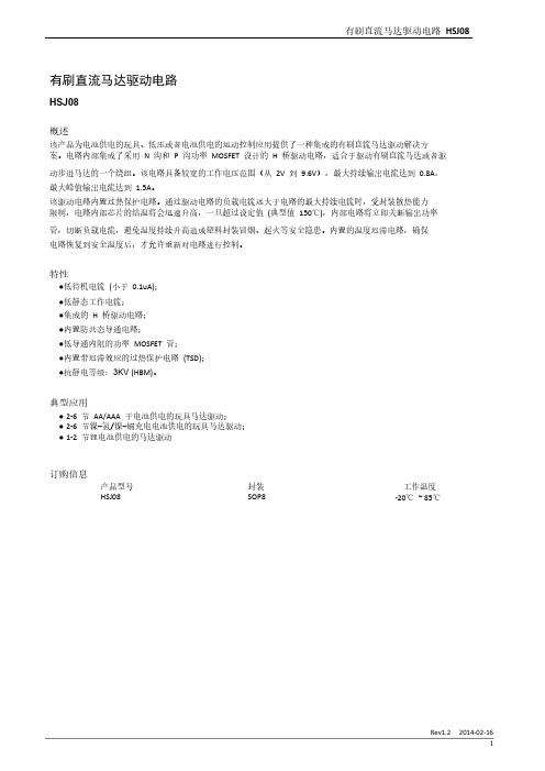
路
AGND
过热保护电路
6 AGND
VDD 4
VDD
栅
驱
动
OUTA 8
电
路
PGND VDD
栅
驱
动
OUTB 5
电
路
PGND
7 PGND
INB
OUTA
OUTB
L
Z
Z
L
H
L
H
L
H
H
L
L
输入信号
INA L INB
正转
H
L
反转
L
H
刹车
H
L
H
待机
功能 待机 正转 反转 刹车
马达两端电压 VDD
0(VOUTA-VOUTB )
逻辑电源 VCC 对地电容 C2 必须至少需要 4.7uF,实际应用时不需要靠近芯片单独添加一个电容,可以与其 它控制芯片(RX2、MCU)等共用。如果 VCC 对地没有任何电容,当电路因过载进入过热保护模式后,电路可 能会进入锁定状态。进入锁定状态后,必须重新改变一次输入信号的状态,电路才能恢复正常。只要 VCC 对地有超过 4.7uF 电容,电路就不会出现锁定状态。
12节锂电池供电的马达驱动订购信息产品型号hsj08封装sop8工作温度2085rev1220140216hsj08引脚排列引脚定义vccoutainapgndinbagndvddoutb引脚名称vccinainbvddoutbagndpgndouta输入输出引脚功能描述逻辑控制电源端正转逻辑输入反转逻辑输入功率电源端反转输出逻辑控制电路接地端输出功率管接地端正转输出功能框图vccvccvddina125k电平转换电路agndvccpgndoutainb125kpgndvdd电平转换电路agndoutbpgnd逻辑真值表ina功能待机反转刹车典型波形示意图ina输入信号inb待机马达两端电压vdd0voutavoutbvddrev1220140216hsj08绝对最大额定值ta25参数最大逻辑控制电源电压最大功率电源电压最大外加输出端电压最大外加输入电压最大峰值输出电流最大功耗结到环境热阻工作温度范围储存温度焊接温度esd注注
JZJ使用说明书
QJZ系列(60、80)II中文显示说明书

QJZ系列矿用隔爆兼本质安全型真空电磁起动器1、概述1.1主要用途及适用范围QJZ系列矿用隔爆兼本安型真空电磁起动器(以下简称起动器),适用于具有爆炸性气体(甲烷混合物)和煤尘爆炸性危险的煤矿井下,在交流50Hz,电压为1140伏及以下的供电系统中,作为就地或远距离控制的矿用隔爆型三相鼠笼型异步电动机的起动、停止或反转控制之用,它特别适用于频繁操作,重负荷的煤矿机械设备中。
1.2产品特点该起动器是矿用隔爆兼本安型起动器,起动器的接触器是真空接触器,其灭弧介质是真空介质,因此其灭弧效果极佳,使其分断、接通能力增强,具有比空气接触器更加安全、可靠的特点。
同时该起动器具有下列保护:a、过载保护b、短路保护c、断相保护d、失压保护e、主回路漏电闭锁功能1.3产品型式、型号及其型号组成意义1.3.1产品的防爆型式:矿用隔爆兼本安型;防爆标志:Exd[ib]I。
1.3.2型号的意义:Q J Z - □/ □ II中文智能额定电压额定电流真空隔爆兼本质安全型起动器1.4使用环境条件:a)海拔不超过2000m;b)环境大气压力80~110KPa;c)环境温度-20~+40℃;d)周围空气相对湿度不大于95%(25℃时);e)在具有甲烷爆炸危险气体和煤尘爆炸危险的煤矿井下。
1.5工作条件:a)与水平面的安装倾斜角度不超过15°;b)无显著摇动和冲击振动的地方;c)无显著破坏绝缘的气体和蒸气的地方;d)能防止滴水的地方;e)污染等级:3级;f)安装类别:Ⅲ类;g)工作电压为1140V、660V、380V;h)工作制为8小时工作。
1.6安全:该起动器是在具有爆炸性气体危险环境中使用的设备,因此要特别注意或检查其隔爆结构,防止失爆以便保证设备与矿井、人员的安全。
2、结构特征与工作原理2.1起动器壳体结构:起动器由钢板和型钢焊成方形隔爆型壳体,主腔、主体上方为隔爆型的方型接线腔。
接线腔与壳体主腔之间,由具有隔爆性能的接线端子贯通。
S8J中文资料
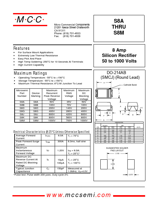
MAX .214 .203 .005 .02 .067 .179 .330 .243 .240
MAX 5.43 5.30 .13 .51 1.70 4.55 8.38 6.18 6.10
NOTE
SUGGESTED SOLDER PAD LAYOUT
0.190
0.200
0.070”
Electrical Characteristics @ 25°C Unless Otherwise Specified
Average Forward IF(AV) 8.0A TJ = 75°C Current Peak Forward Surge IFSM 300A 8.3ms, half sine Current Maximum 1.20V IFM = 8.0A; Instantaneous VF Forward Voltage TJ = 25°C* Maximum DC Reverse Current At IR 10µA TJ = 25°C Rated DC Blocking 100µA TJ = 100°C Voltage Typical Junction CJ 150pF Measured at Capacitance 1.0MHz, VR=4.0V *Pulse test: Pulse width 200 µsec, Duty cycle 2%
MCC
8
Single Phase, Half Wave 60Hz Resistive or Inductive Load 0 0 50 75 100 °C Average Forward Rectified Current - Amperes versus Ambient Temperature - ° C Volts Instantaneous Forward Current - Amperes versus Instantaneous Forward Voltage - Volts 125 150 175
QJ航天标准目录全
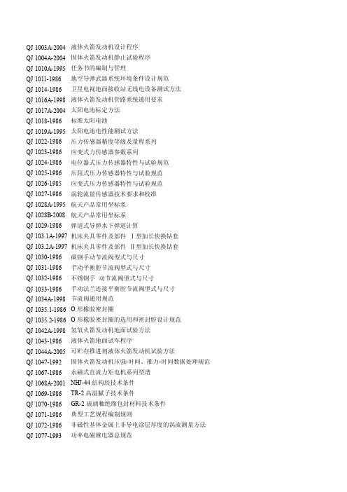
QJ 1003A-2004 液体火箭发动机设计程序QJ 1004A-2004 固体火箭发动机静止试验程序QJ 1010A-1995 任务书的编制与管理QJ 1011-1986 地空导弹武器系统环境条件设计规范QJ 1014-1986 卫星电视地面接收站无线电设备测试方法QJ 1016A-1998 液体火箭发动机管路系统通用要求QJ 1017A-2004 太阳电池标定方法QJ 1018-1986 标准太阳电池QJ 1019A-1995 太阳电池电性能测试方法QJ 1022-1986 压力传感器精度等级及量程系列QJ 1023-1986 应变式力传感器参数系列QJ 1024-1986 电位器式压力传感器特性与试验规范QJ 1025-1986 压阻式压力传感器特性与试验规范QJ 1026-1985 应变式压力传感器特性与试验规范QJ 1027-1986 涡轮流量传感器技术要求和校准QJ 1028A-1995 航天产品常用坐标系QJ 1028B-2008 航天产品常用坐标系QJ 1029-1986 弹道式导弹水下弹道计算QJ 103.1A-1997 机床夹具零件及部件Ⅰ型加长快换钻套QJ 103.2A-1997 机床夹具零件及部件Ⅱ型加长快换钻套QJ 1030-1986 碳钢手动节流阀型式与尺寸QJ 1031-1986 手动平衡腔节流阀型式与尺寸QJ 1032-1986 不锈钢手动节流阀型式与尺寸QJ 1033-1986 手动法兰连接平衡腔节流阀型式与尺寸QJ 1034A-1998 节流阀通用规范QJ 1035.1-1986 O形橡胶密封圈QJ 1035.2-1986 O形橡胶密封圈的选用和密封腔设计规范QJ 1042A-1998 氢氧火箭发动机地面试验方法QJ 1043-1986 液体火箭地面试车程序QJ 1044A-2005 可贮存推进剂液体火箭发动机试验方法QJ 1047-1992 固体火箭发动机压强-时间、推力-时间数据处理规范QJ 1067-1986 永磁式直流力矩电机系列型谱QJ 1068A-2001 NHJ-44结构胶技术条件QJ 1069-1986 TR-2高温腻子技术条件QJ 1070-1986 GR-2玻璃釉绝缘包封材料技术条件QJ 1071-1986 典型工艺规程编制规则QJ 1072-1986 非磁性基体金属上非导电涂层厚度的涡流测量方法QJ 1077-1993 功率电磁继电器总规范QJ 1078-1986 微小型密封电磁继电器通用技术条件QJ 1079A-2004 陀螺仪主要精度指标和测试方法QJ 1080A-1997 液体火箭质量、质心和转动惯量计算方法QJ 1081-1986 应变式线位移传感器特性与试验规范QJ 1082-1986 应变式力传感器特性与试验规范QJ 1083-1986 液体火箭发动机稳态压强测量规范QJ 1084-1986 液体火箭发动机地面稳态推力测量规范QJ 1085-1986 液体火箭发动机真空推力测量规范QJ 1086-1986 液体火箭发动机试验低温温度测量规范QJ 1088A-1996 火箭发动机试验用热电偶温度传感器技术条件QJ 1089A-1998 工艺文件使用与归档管理规定QJ 1090A-1998 研究试验文使用与归档管理规定QJ 1091A-1998 设计文件使用与归档管理规定QJ 1092A-1998 科技档案管理表格QJ 1093-1986 导弹地面特种挂车试验规程QJ 1094.1-1986 塑料和金属保护件塑料保护堵盖QJ 1094.2-1986 塑料和金属保护件塑料保护堵塞QJ 1094.3-1986 塑料和金属保护件金属保护堵塞QJ 1094.4-1986 塑料和金属保护件金属保护堵盖QJ 1094.5-1986 塑料和金属保护件保护盖板QJ 1094.6-1986 塑料和金属保护件保护螺母QJ 1095-1986 塑料和金属保护件保护件技术条件QJ 1096.10-1986 球阀Pn23MPa Dn80球阀型式与尺寸QJ 1096.11-1986 球阀操纵机构型式与尺寸QJ 1096.1-1986 球阀Pn1.6MPa Dn20球阀型式与尺寸QJ 1096.2-1986 球阀Pn1.6MPa Dn32~150球阀型式与尺寸QJ 1096.3-1986 球阀Pn1.6MPa Dn200球阀型式与尺寸QJ 1096.4-1986 球阀Pn6.4MPa Dn20球阀型式与尺寸QJ 1096.5-1986 球阀Pn6.4MPa Dn32球阀型式与尺寸QJ 1096.6-1986 球阀Pn6.4MPa Dn50球阀型式与尺寸QJ 1096.7-1986 球阀Pn6.4MPa Dn100球阀型式与尺寸QJ 1096.8-1986 球阀Pn23MPa Dn20球阀型式与尺寸QJ 1096.9-1986 球阀Pn23MPa Dn32球阀型式与尺寸QJ 1097A-1997 球阀通用规范QJ 1098-1986 地面设备液压缸通用技术条件QJ 1100-1986 2303胶料技术条件QJ 1101-1986 蜂窝夹层结构名词术语(工艺部分)QJ 1102-1986 氨基烘干磁漆涂装通用工艺QJ 1103-1986 醇酸磁漆涂装通用工艺QJ 1105-1986 铸造铝镍钴永磁(硬磁)合金热处理QJ 1107-1987 卫星气动力系数工程计算QJ 1108-1987 固体弹道式导弹标准弹道计算QJ 1110-1987 固体弹道式导弹设计与制造通用规范QJ 1112-1987 手动截止阀通用技术条件QJ 1112A-2008 手动截止阀通用规范QJ 1113-1987 复合固体推进剂性能测试用试样QJ 1117-1987 液体火箭发动机推力室试验工作程序QJ 1118A-1995 固体火箭发动机试验架设计制造验收通用要求QJ 1120-1987 静压液浮陀螺平台测试方法QJ 1121-1987 液浮陀螺平台测试方法QJ 1123-1987 胶接蜂窝夹层结构平面拉伸强度试验方法QJ 1124-1987 胶接蜂窝夹层结构侧向压缩性能试验方法QJ 1125-1987 胶接蜂窝夹层结构平面剪切性能试验方法QJ 1126-1987 低压钡酚醛树脂预浸布的制备工艺规范QJ 1127-1987 防热型钡酚醛玻璃钢手糊成型工艺规范QJ 1128-1987 硬质聚氨酯泡沫塑料喷涂成型工艺QJ 1132-1987 航天器金属材料性能规范结构铝合金性能规范QJ 1133.10-1987 机械夹固式车刀压板式切断刀QJ 1133.11-1987 机械夹固式车刀转位式螺纹车刀QJ 1133.1-1987 机械夹固式车刀偏心式45°外圆车刀QJ 1133.12-1987 机械夹固式车刀压板式螺纹车刀QJ 1133.13-1987 机械夹固式车刀压板式75°内孔车刀(刀杆直径16) QJ 1133.14-1987 机械夹固式车刀压板式75°内孔车刀(刀杆直径25) QJ 1133.15-1987 机械夹固式车刀压板式90°内孔车刀(刀杆直径16) QJ 1133.16-1987 机械夹固式车刀压板式90°内孔车刀(刀杆直径25) QJ 1133.17-1987 机械夹固式车刀压板式内槽车刀(刀杆直径16) QJ 1133.18-1987 机械夹固式车刀压板式内槽车刀(刀杆直径25) QJ 1133.19-1987 机械夹固式车刀螺纹联接内孔车刀QJ 1133.20-1987 机械夹固式车刀插接式内孔车刀QJ 1133.21-1987 机械夹固式车刀压板QJ 1133.2-1987 机械夹固式车刀偏心式75°外圆车刀QJ 1133.22-1987 机械夹固式车刀螺钉QJ 1133.23-1987 机械夹固式车刀偏心销QJ 1133.24-1987 机械夹固式车刀圆锥孔方形刀垫QJ 1133.25-1987 机械夹固式车刀圆柱孔方形刀垫QJ 1133.26-1987 机械夹固式车刀圆柱孔三角形刀垫QJ 1133.27-1987 机械夹固式车刀圆柱孔三角形刀垫QJ 1133.28-1987 机械夹固式车刀内孔刀座QJ 1133.29-1987 机械夹固式车刀内孔刀套QJ 1133.3-1987 机械夹固式车刀偏心式90°外圆车刀QJ 1133.4-1987 机械夹固式车刀压板式45°外圆车刀QJ 1133.5-1987 机械夹固式车刀压板式45°外圆车刀(左)QJ 1133.6-1987 机械夹固式车刀压板式75°外圆车刀QJ 1133.7-1987 机械夹固式车刀压板式75°外圆车刀(左)QJ 1133.8-1987 机械夹固式车刀压板式90°外圆车刀QJ 1133.9-1987 机械夹固式车刀压板式90°外圆车刀(左)QJ 1134-1987 机械夹固式车刀技术条件QJ 1135A-2002 固体火箭发动机振动试验方法QJ 1136A-2002 固体火箭发动机冲击试验方法QJ 1137A-2005 固体火箭发动机离心试验方法QJ 1138-1987 硅基材料烧蚀-温度场计算方法QJ 1140-1987 战术导弹弹体装配通用技术条件QJ 1141-1987 气动电磁阀通用技术条件QJ 1142-1987 气体单向阀通用技术条件QJ 1142A-2008 气体单向阀通用规范QJ 1143-1987 气体减压阀通用技术条件QJ 1143A-2008 导弹(运载火箭)用气体减压阀通用规范QJ 1145.10-1987 焊接夹具零件及部件钩形螺栓用套管QJ 1145.10A-2007 焊接夹具零件及部件第10部分:钩形螺栓用套管QJ 1145.11-1987 焊接夹具零件及部件圆定位销QJ 1145.1-1987 焊接夹具零件及部件单面平压板QJ 1145.11A-2007 焊接夹具零件及部件第11部分:圆定位销QJ 1145.12-1987 焊接夹具零件及部件四棱定位销QJ 1145.12A-2007 焊接夹具零件及部件第12部分:四棱定位销QJ 1145.13-1987 焊接夹具零件及部件棱形定位销QJ 1145.13A-2007 焊接夹具零件及部件第13部分:棱形定位销QJ 1145.14-1987 焊接夹具零件及部件单耳定位件QJ 1145.14A-2007 焊接夹具零件及部件第14部分:单耳定位件QJ 1145.15-1987 焊接夹具零件及部件叉形定位件QJ 1145.15A-2007 焊接夹具零件及部件第15部分:叉形定位件QJ 1145.16-1987 焊接夹具零件及部件肋板定位器QJ 1145.16A-2007 焊接夹具零件及部件第16部分:肋板定位器QJ 1145.17-1987 焊接夹具零件及部件单耳定位支座QJ 1145.17A-2007 焊接夹具零件及部件第17部分:单耳定位支座QJ 1145.18-1987 焊接夹具零件及部件叉形定位支座QJ 1145.18A-2007 焊接夹具零件及部件第18部分:叉形定位支座QJ 1145.19-1987 焊接夹具零件及部件直支座QJ 1145.19A-2007 焊接夹具零件及部件第19部分:直支座QJ 1145.1A-2007 焊接夹具零件及部件第1部分:单面平压板QJ 1145.20-1987 焊接夹具零件及部件支座QJ 1145.20A-2007 焊接夹具零件及部件第20部分:筒形支座QJ 1145.21-1987 焊接夹具零件及部件支座QJ 1145.2-1987 焊接夹具零件及部件双面平压板QJ 1145.21A-2007 焊接夹具零件及部件第21部分:耳形支座QJ 1145.22-1987 焊接夹具零件及部件低支座QJ 1145.22A-2007 焊接夹具零件及部件第22部分:低支座QJ 1145.23-1987 焊接夹具零件及部件高支座QJ 1145.23A-2007 焊接夹具零件及部件第23部分:高支座QJ 1145.24-1987 焊接夹具零件及部件支座QJ 1145.24A-2007 焊接夹具零件及部件第24部分:支座QJ 1145.25-1987 焊接夹具零件及部件切向压紧支座QJ 1145.25A-2007 焊接夹具零件及部件第25部分:切向压紧支座QJ 1145.26-1987 焊接夹具零件及部件带分度盘支座QJ 1145.26A-2007 焊接夹具零件及部件第26部分:带分度盘支座QJ 1145.27-1987 焊接夹具零件及部件钩形正压夹紧器QJ 1145.27A-2007 焊接夹具零件及部件第27部分:钩形正压夹紧器QJ 1145.28-1987 焊接夹具零件及部件钩形侧压夹紧器QJ 1145.28A-2007 焊接夹具零件及部件第28部分:钩形侧压夹紧器QJ 1145.29-1987 焊接夹具零件及部件管子夹紧器QJ 1145.29A-2007 焊接夹具零件及部件第29部分:管子夹紧器QJ 1145.2A-2007 焊接夹具零件及部件第2部分:双面平压板QJ 1145.30-1987 焊接夹具零件及部件管子夹紧器QJ 1145.30A-2007 焊接夹具零件及部件第30部分:鱼眼管子夹紧器QJ 1145.31-1987 焊接夹具零件及部件铰链夹紧器QJ 1145.3-1987 焊接夹具零件及部件三角压板QJ 1145.31A-2007 焊接夹具零件及部件第31部分:铰链夹紧器QJ 1145.32-1987 焊接夹具零件及部件折动压紧器QJ 1145.32A-2007 焊接夹具零件及部件第32部分:折动压紧器QJ 1145.33-1987 焊接夹具零件及部件螺旋压紧器QJ 1145.33A-2007 焊接夹具零件及部件第33部分:螺旋压紧器QJ 1145.34-2007 焊接夹具零件及部件第34部分:内六角螺纹端头紧定螺钉QJ 1145.34A-2007 焊接夹具零件及部件第34部分:内六角螺纹端头紧定螺钉QJ 1145.35-2007 焊接夹具零件及部件第35部分:光面压块QJ 1145.35A-2007 焊接夹具零件及部件第35部分:光面压块QJ 1145.3A-2007 焊接夹具零件及部件第3部分:三角压板QJ 1145.4-1987 焊接夹具零件及部件六角双向螺母QJ 1145.4A-2007 焊接夹具零件及部件第4部分:六角双向螺母QJ 1145.5-1987 焊接夹具零件及部件小锥体QJ 1145.5A-2007 焊接夹具零件及部件第5部分:小锥体QJ 1145.6-1987 焊接夹具零件及部件大锥体QJ 1145.6A-2007 焊接夹具零件及部件第6部分:大锥体QJ 1145.7-1987 焊接夹具零件及部件小涨胎螺母QJ 1145.7A-2007 焊接夹具零件及部件第7部分:小涨胎螺母QJ 1145.8-1987 焊接夹具零件及部件大涨胎螺母QJ 1145.8A-2007 焊接夹具零件及部件第8部分:大涨胎螺母QJ 1145.9-1987 焊接夹具零件及部件快卸螺母QJ 1145.9A-2007 焊接夹具零件及部件第9部分:快卸螺母 QJ1145.9 QJ1145.9A QJ1145QJ 1146-1987 焊接夹具零件及部件技术条件 QJ1146 QJ1146 QJ1146QJ 1146A-2007 焊接夹具零件及部件技术要求 QJ1146 QJ1146A QJ1146QJ 1147-1987 加工Tc类钛合金手用丝锥型式与尺寸 QJ1147 QJ1147 QJ1147QJ 1148-1987 加工Tc类钛合金手用丝锥技术条件 QJ1148 QJ1148 QJ1148QJ 1150-1987 产品贮存试验工作程序 QJ1150 QJ1150 QJ1150QJ 1152-1987 HYJ-51导热绝缘胶技术条件 QJ1152 QJ1152 QJ1152QJ 1153-1987 液体火箭发动机稳态流量测量规范 QJ1153 QJ1153 QJ1153QJ 1155-1993 民用产品设计文件编制和管理规定 QJ1155 QJ1155 QJ1155QJ 1156A-1996 钢件硬钎焊技术条件 QJ1156 QJ1156A QJ1156QJ 1158-1987 轴用光滑极限量规应用尺寸 QJ1158 QJ1158 QJ1158QJ 1159.1-1987 光滑极限量规型式尺寸双头针式塞规(D QJ1159.1 QJ1159.1 QJ1159QJ 1159.2-1987 光滑极限量规型式尺寸双头锥度锁紧式圆柱塞规(D=1~50) QJ1159.2 QJ1159.2 QJ1159QJ 1159.3-1987 光滑极限量规型式尺寸双头钢球固定式圆柱塞规(D>50~120) QJ1159.3 QJ1159.3 QJ1159 QJ 1159.4-1987 光滑极限量规型式尺寸单头钢球固定式圆柱塞规(D>65~120) QJ1159.4 QJ1159.4 QJ1159 QJ 1159.5-1987 光滑极限量规型式尺寸单头钢球固定式非全形塞规(D>80~180) QJ1159.5 QJ1159.5 QJ1159 QJ 1159.6-1987 光滑极限量规型式尺寸单头带护板非全形塞规(D>180~315) QJ1159.6 QJ1159.6 QJ1159 QJ 1159.7-1987 光滑极限量规型式尺寸双头片状塞规(D>80~250) QJ1159.7 QJ1159.7 QJ1159QJ 1159.8-1987 光滑极限量规型式尺寸球端杆规(D>120~500) QJ1159.8 QJ1159.8 QJ1159QJ 1160.1-1987 光滑极限量规型式尺寸圆环规(D>1~100) QJ1160.1 QJ1160.1 QJ1160QJ 1160.2-1987 光滑极限量规型式尺寸双头组合卡规(D≤3) QJ1160.2 QJ1160.2 QJ1160QJ 1160.3-1987 光滑极限量规型式尺寸单头矩片形卡规(D>3~10) QJ1160.3 QJ1160.3 QJ1160QJ 1160.4-1987 光滑极限量规型式尺寸单头圆片形卡规(D>10~80) QJ1160.4 QJ1160.4 QJ1160QJ 1160.5-1987 光滑极限量规型式尺寸单头圆片形卡规(D>80~120) QJ1160.5 QJ1160.5 QJ1160QJ 1160.6-1987 光滑极限量规型式尺寸单头圆片形卡规(D>120~250) QJ1160.6 QJ1160.6 QJ1160QJ 1161-1987 光滑极限量规技术条件 QJ1161 QJ1161 QJ1161QJ 1162-1987 深度、高度、长度极限量规公差及应用尺寸 QJ1162 QJ1162 QJ1162QJ 1163.10-1987 深度、高度、长度极限量规型式尺寸端面环形槽塞规(L=18~315) QJ1163.10 QJ1163.10 QJ1163 QJ 1163.11-1987 深度、高度、长度极限量规型式尺寸量孔槽宽度用塞规(B=1~18) QJ1163.11 QJ1163.11 QJ1163 QJ 1163.1-1987 深度、高度、长度极限量规型式尺寸带柄长度卡规(L=3~120) QJ1163.1 QJ1163.1 QJ1163QJ 1163.12-1987 深度、高度、长度极限量规型式尺寸弯头槽宽塞规(B=1.5~20) QJ1163.12 QJ1163.12 QJ1163 QJ 1163.13-1987 深度、高度、长度极限量规型式尺寸双头片式槽宽塞规(B=2~315) QJ1163.13 QJ1163.13 QJ1163 QJ 1163.14-1987 深度、高度、长度极限量规型式尺寸深度量规(L=1~180) QJ1163.14 QJ1163.14 QJ1163QJ 1163.15-1987 深度、高度、长度极限量规型式尺寸游标深度量规(L=1~260) QJ1163.15 QJ1163.15 QJ1163QJ 1163.2-1987 深度、高度、长度极限量规型式尺寸长度卡规(L=10~500) QJ1163.2 QJ1163.2 QJ1163QJ 1163.3-1987 深度、高度、长度极限量规型式尺寸长度刻线量规(L=3~250) QJ1163.3 QJ1163.3 QJ1163QJ 1163.4-1987 深度、高度、长度极限量规型式尺寸高度量规(L=1~315) QJ1163.4 QJ1163.4 QJ1163QJ 1163.5-1987 深度、高度、长度极限量规型式尺寸单肩高度量规(L=1~20) QJ1163.5 QJ1163.5 QJ1163QJ 1163.6-1987 深度、高度、长度极限量规型式尺寸高度量规(L=1~50) QJ1163.6 QJ1163.6 QJ1163QJ 1163.7-1987 深度、高度、长度极限量规型式尺寸高度卡规(L=3~60) QJ1163.7 QJ1163.7 QJ1163QJ 1163.8-1987 深度、高度、长度极限量规型式尺寸手柄式槽宽塞规(B=0.1~3) QJ1163.8 QJ1163.8 QJ1163QJ 1163.9-1987 深度、高度、长度极限量规型式尺寸端面环形槽卡规(D=10~315) QJ1163.9 QJ1163.9 QJ1163 QJ 1164-1987 深度、高度、长度极限量规技术条件 QJ1164 QJ1164 QJ1164QJ 1165-1987 不锈钢薄板熔焊技术条件 QJ1165 QJ1165 QJ1165QJ 1167.1-1998 研究试验文件管理制度研究试验文件的概念和分类 QJ1167.1 QJ1167.1 QJ1167QJ 1167.2-1998 研究试验文件管理制度研究试验文件的编号规定 QJ1167.2 QJ1167.2 QJ1167QJ 1167.3-1998 研究试验文件管理制度研究试验文件的格式及填写要求 QJ1167.3 QJ1167.3 QJ1167QJ 1167.4-1998 研究试验文件管理制度研究试验文件的完整性 QJ1167.4 QJ1167.4 QJ1167QJ 1167.5-1998 研究试验文件管理制度研究试验文件的编写规定 QJ1167.5 QJ1167.5 QJ1167QJ 1167.6-1998 研究试验文件管理制度研究试验文件的签署规定 QJ1167.6 QJ1167.6 QJ1167QJ 1167.7-1998 研究试验文件管理制度研究试验文件的更改规定 QJ1167.7 QJ1167.7 QJ1167QJ 1171A-1995 航天科技报告编写与评审规则 QJ1171 QJ1171A QJ1171QJ 1172A-1997 导弹、火箭质量特性测量方法 QJ1172 QJ1172A QJ1172QJ 1173-1987 海防导弹贮存规范 QJ1173 QJ1173 QJ1173QJ 1175A-1996 钢薄板熔焊对接接头X射线照相检验方法 QJ1175 QJ1175A QJ1175QJ 1177.10-1987 地空、舰空导弹武器系统环境试验方法霉菌试验 QJ1177.10 QJ1177.10 QJ1177QJ 1177.11-1987 地空、舰空导弹武器系统环境试验方法盐雾试验 QJ1177.11 QJ1177.11 QJ1177QJ 1177.1-1987 地空、舰空导弹武器系统环境试验方法总则 QJ1177.1 QJ1177.1 QJ1177QJ 1177.12-1987 地空、舰空导弹武器系统环境试验方法砂尘试验 QJ1177.12 QJ1177.12 QJ1177QJ 1177.13-1987 地空、舰空导弹武器系统环境试验方法加速度试验 QJ1177.13 QJ1177.13 QJ1177QJ 1177.14-1987 地空、舰空导弹武器系统环境试验方法振动试验 QJ1177.14 QJ1177.14 QJ1177QJ 1177.15-1987 地空、舰空导弹武器系统环境试验方法噪声试验 QJ1177.15 QJ1177.15 QJ1177QJ 1177.16-1987 地空、舰空导弹武器系统环境试验方法冲击试验 QJ1177.16 QJ1177.16 QJ1177QJ 1177.17-1987 地空、舰空导弹武器系统环境试验方法温度-低气压试验 QJ1177.17 QJ1177.17 QJ1177QJ 1177.18-1987 地空、舰空导弹武器系统环境试验方法温度-湿度-振动-低气压试验 QJ1177.18 QJ1177.18 QJ1177 QJ 1177.2-1987 地空、舰空导弹武器系统环境试验方法低气压试验 QJ1177.2 QJ1177.2 QJ1177QJ 1177.3-1987 地空、舰空导弹武器系统环境试验方法高温试验 QJ1177.3 QJ1177.3 QJ1177QJ 1177.4-1987 地空、舰空导弹武器系统环境试验方法低温试验 QJ1177.4 QJ1177.4 QJ1177QJ 1177.5-1987 地空、舰空导弹武器系统环境试验方法温度冲击试验 QJ1177.5 QJ1177.5 QJ1177QJ 1177.6-1987 地空、舰空导弹武器系统环境试验方法湿热试验 QJ1177.6 QJ1177.6 QJ1177QJ 1177.7-1987 地空、舰空导弹武器系统环境试验方法太阳辐照试验 QJ1177.7 QJ1177.7 QJ1177QJ 1177.8-1987 地空、舰空导弹武器系统环境试验方法淋雨试验 QJ1177.8 QJ1177.8 QJ1177QJ 1177.9-1987 地空、舰空导弹武器系统环境试验方法浸渍试验 QJ1177.9 QJ1177.9 QJ1177QJ 1178-1987 玻璃纤维布/酚醛树脂面板制造工艺规范 QJ1178 QJ1178 QJ1178QJ 1180A-2005 玻璃纤维增强塑料蜂窝芯子规范 QJ1180 QJ1180A QJ1180QJ 1181.1A-1995 软磁合金的热处理铁镍软磁合金的热处理 QJ1181.1 QJ1181.1A QJ1181QJ 1181.2A-1995 软磁合金的热处理高饱和磁感应强度软磁合金的热处理 QJ1181.2 QJ1181.2A QJ1181QJ 1181.3A-1995 软磁合金的热处理铁铝软磁合金的热处理 QJ1181.3 QJ1181.3A QJ1181QJ 1181.4A-1995 软磁合金的热处理磁温度补偿合金的热处理 QJ1181.4 QJ1181.4A QJ1181QJ 1181.5A-1995 软磁合金的热处理耐蚀软磁合金的热处理 QJ1181.5 QJ1181.5A QJ1181QJ 1181.6A-1995 软磁合金的热处理恒磁导率合金的热处理 QJ1181.6 QJ1181.6A QJ1181QJ 1182A-2005 铸造铝合金熔炼 QJ1182 QJ1182A QJ1182QJ 1183-1987 海防导弹环境规范总则 QJ1183 QJ1183 QJ1183QJ 1184.10-1987 海防导弹环境规范弹上设备颠振试验 QJ1184.10 QJ1184.10 QJ1184QJ 1184.11-1987 海防导弹环境规范弹上设备加速度试验 QJ1184.11 QJ1184.11 QJ1184QJ 1184.1-1987 海防导弹环境规范弹上设备高温试验 QJ1184.1 QJ1184.1 QJ1184QJ 1184.12-1987 海防导弹环境规范弹上设备振动试验 QJ1184.12 QJ1184.12 QJ1184QJ 1184.13-1987 海防导弹环境规范弹上设备公路运输试验 QJ1184.13 QJ1184.13 QJ1184QJ 1184.2-1987 海防导弹环境规范弹上设备低温试验 QJ1184.2 QJ1184.2 QJ1184QJ 1184.3-1987 海防导弹环境规范弹上设备温度冲击试验 QJ1184.3 QJ1184.3 QJ1184QJ 1184.4-1987 海防导弹环境规范弹上设备温度-高温试验 QJ1184.4 QJ1184.4 QJ1184QJ 1184.5-1987 海防导弹环境规范弹上设备湿热试验 QJ1184.5 QJ1184.5 QJ1184QJ 1184.6-1987 海防导弹环境规范弹上设备霉菌试验 QJ1184.6 QJ1184.6 QJ1184QJ 1184.7-1987 海防导弹环境规范弹上设备盐雾试验 QJ1184.7 QJ1184.7 QJ1184QJ 1184.8-1987 海防导弹环境规范弹上设备冲击试验 QJ1184.8 QJ1184.8 QJ1184QJ 1184.9-1987 海防导弹环境规范弹上设备碰撞试验 QJ1184.9 QJ1184.9 QJ1184QJ 1185.1-1987 海防导弹环境规范导弹砂尘试验 QJ1185.1 QJ1185.1 QJ1185QJ 1185.2-1987 海防导弹环境规范导弹淋雨试验 QJ1185.2 QJ1185.2 QJ1185QJ 1185.3-1987 海防导弹环境规范导弹冲击试验 QJ1185.3 QJ1185.3 QJ1185QJ 1185.4-1987 海防导弹环境规范导弹振动试验 QJ1185.4 QJ1185.4 QJ1185QJ 1185.5-1987 海防导弹环境规范导弹公路运输试验 QJ1185.5 QJ1185.5 QJ1185QJ 1185.6-1987 海防导弹环境规范导弹铁路运输试验 QJ1185.6 QJ1185.6 QJ1185QJ 1185.7-1987 海防导弹环境规范导弹舰载航行试验 QJ1185.7 QJ1185.7 QJ1185QJ 1185.8-1987 海防导弹环境规范导弹机载航行试验 QJ1185.8 QJ1185.8 QJ1185QJ 1186-1987 自动驾驶仪术语 QJ1186 QJ1186 QJ1186QJ 1190-1987 冲压发动机术语 QJ1190 QJ1190 QJ1190QJ 1191-1987 组合发动机术语 QJ1191 QJ1191 QJ1191QJ 1192-1987 高温硫化硅橡胶玻璃布技术条件 QJ1192 QJ1192 QJ1192QJ 1195.1-1987 设备统计目录及代码 QJ1195.1 QJ1195.1 QJ1195QJ 1195.2-1987 设备管理表格 QJ1195.2 QJ1195.2 QJ1195QJ 1195.3-1987 设备管理设备完好标准及完好率考核办法 QJ1195.3 QJ1195.3 QJ1195QJ 1195.4-1987 设备管理设备分类标准及其管理办法 QJ1195.4 QJ1195.4 QJ1195QJ 1195.5A-1997 设备修理工时费用停歇时间定额 QJ1195.5 QJ1195.5A QJ1195QJ 1200-1987 制导站术语 QJ1200 QJ1200 QJ1200QJ 1203-1987 板料冷冲压工艺装备制造与验收技术条件 QJ1203 QJ1203 QJ1203QJ 1205-1987 印制板插头镍打底酸性镀硬金生产说明书 QJ1205 QJ1205 QJ1205QJ 1206-1987 印制板插头镍打底酸性镀硬金溶液分析方法 QJ1206 QJ1206 QJ1206QJ 1207-1987 印制板插头镍打底酸性镀硬金技术条件 QJ1207 QJ1207 QJ1207QJ 1212-1987 无源无线电干扰滤波器插入损耗测量方法 QJ1212 QJ1212 QJ1212QJ 1214-1987 气体安全阀通用技术条件 QJ1214 QJ1214 QJ1214QJ 1214A-2008 气体安全阀通用规范 QJ1214 QJ1214A QJ1214QJ 1215-1987 导弹总体术语 QJ1215 QJ1215 QJ1215QJ 1221-1987 插头(座)刻字规定 QJ1221 QJ1221 QJ1221QJ 1223-1987 镦铆型抗剪环槽铆钉技术条件 QJ1223 QJ1223 QJ1223QJ 1225-1987 镦铆型抗剪平圆头环槽铆钉钉杆 QJ1225 QJ1225 QJ1225QJ 1226-1987 镦铆型抗剪90°沉头环槽铆钉钉杆 QJ1226 QJ1226 QJ1226QJ 1227-1987 镦铆型抗剪环槽铆钉钉套 QJ1227 QJ1227 QJ1227QJ 1228B-2004 模块式DC/DC电源变换器系列 QJ1228 QJ1228B QJ1228QJ 1229-1987 液体火箭发动机稳态参数测量不确定度估计方法 QJ1229 QJ1229 QJ1229 QJ 1230-1987 液体火箭发动机温度测量不确定度估计 QJ1230 QJ1230 QJ1230QJ 1232-1987 采集卡编写导则 QJ1232 QJ1232 QJ1232QJ 1233-1987 采集卡传输规范 QJ1233 QJ1233 QJ1233QJ 1236-1987 信息系统数据安全与保密规范 QJ1236 QJ1236 QJ1236QJ 1238.10-1987 导弹运载火箭上电缆试验方法振动试验 QJ1238.10 QJ1238.10 QJ1238QJ 1238.11-1987 导弹运载火箭上电缆试验方法加速度试验 QJ1238.11 QJ1238.11 QJ1238 QJ 1238.1-1987 导弹运载火箭上电缆试验方法总则 QJ1238.1 QJ1238.1 QJ1238QJ 1238.12-1987 导弹运载火箭上电缆试验方法高温老化试验 QJ1238.12 QJ1238.12 QJ1238 QJ 1238.13-1987 导弹运载火箭上电缆试验方法缠绕试验 QJ1238.13 QJ1238.13 QJ1238QJ 1238.14-1987 导弹运载火箭上电缆试验方法磨损试验 QJ1238.14 QJ1238.14 QJ1238QJ 1238.15-1987 导弹运载火箭上电缆试验方法导通试验 QJ1238.15 QJ1238.15 QJ1238QJ 1238.16-1987 导弹运载火箭上电缆试验方法绝缘电阻试验 QJ1238.16 QJ1238.16 QJ1238QJ 1238.17-1987 导弹运载火箭上电缆试验方法交流电压试验 QJ1238.17 QJ1238.17 QJ1238QJ 1238.18-1990 导弹运载火箭上电缆试验方法低气压试验 QJ1238.18 QJ1238.18 QJ1238QJ 1238.19-1990 导弹运载火箭上电缆试验方法公路运输加速模拟试验 QJ1238.19 QJ1238.19 QJ1238 QJ 1238.20-1990 导弹运载火箭上电缆试验方法淋雨试验 QJ1238.20 QJ1238.20 QJ1238QJ 1238.21-1990 导弹运载火箭上电缆试验方法低温弯曲试验 QJ1238.21 QJ1238.21 QJ1238QJ 1238.2-1987 导弹运载火箭上电缆试验方法低温试验 QJ1238.2 QJ1238.2 QJ1238QJ 1238.3-1987 导弹运载火箭上电缆试验方法高温试验 QJ1238.3 QJ1238.3 QJ1238QJ 1238.4-1987 导弹运载火箭上电缆试验方法交变湿热试验 QJ1238.4 QJ1238.4 QJ1238QJ 1238.5-1987 导弹运载火箭上电缆试验方法浸液试验 QJ1238.5 QJ1238.5 QJ1238QJ 1238.6-1987 导弹运载火箭上电缆试验方法霉菌试验 QJ1238.6 QJ1238.6 QJ1238QJ 1238.7-1987 导弹运载火箭上电缆试验方法盐雾试验 QJ1238.7 QJ1238.7 QJ1238QJ 1238.8-1987 导弹运载火箭上电缆试验方法燃烧试验 QJ1238.8 QJ1238.8 QJ1238QJ 1238.9-1987 导弹运载火箭上电缆试验方法冲击试验 QJ1238.9 QJ1238.9 QJ1238QJ 1239.10-1987 电子设备环境试验条件和方法盐雾试验 QJ1239.10 QJ1239.10 QJ1239QJ 1239.11-1987 电子设备环境试验条件和方法振动试验 QJ1239.11 QJ1239.11 QJ1239QJ 1239.1-1987 电子设备环境试验条件和方法总则 QJ1239.1 QJ1239.1 QJ1239QJ 1239.12-1987 电子设备环境试验条件和方法噪声试验 QJ1239.12 QJ1239.12 QJ1239QJ 1239.13-1987 电子设备环境试验条件和方法冲击试验 QJ1239.13 QJ1239.13 QJ1239QJ 1239.14-1987 电子设备环境试验条件和方法加速度试验 QJ1239.14 QJ1239.14 QJ1239QJ 1239.2-1987 电子设备环境试验条件和方法高温试验 QJ1239.2 QJ1239.2 QJ1239QJ 1239.3-1987 电子设备环境试验条件和方法低温试验 QJ1239.3 QJ1239.3 QJ1239QJ 1239.4-1987 电子设备环境试验条件和方法温度变化试验 QJ1239.4 QJ1239.4 QJ1239QJ 1239.5-1987 电子设备环境试验条件和方法低气压试验 QJ1239.5 QJ1239.5 QJ1239QJ 1239.6-1987 电子设备环境试验条件和方法淋雨试验 QJ1239.6 QJ1239.6 QJ1239QJ 1239.7-1987 电子设备环境试验条件和方法砂尘试验 QJ1239.7 QJ1239.7 QJ1239QJ 1239.8-1987 电子设备环境试验条件和方法湿热试验 QJ1239.8 QJ1239.8 QJ1239QJ 1239.9-1987 电子设备环境试验条件和方法霉菌试验 QJ1239.9 QJ1239.9 QJ1239QJ 1240A-1996 磁粉离合器通用规范 QJ1240 QJ1240A QJ1240QJ 1241A-1997 单自由度静压液浮积分陀螺仪通用规范 QJ1241 QJ1241A QJ1241QJ 1242-1987 出口战术导弹包装通用技术条件 QJ1242 QJ1242 QJ1242QJ 1243-1987 弹道式导弹弹头术语 QJ1243 QJ1243 QJ1243QJ 1245-1987 HYJ-4、HYJ-16、HYJ-42室温固化环氧胶粘剂技术条件 QJ1245 QJ1245 QJ1245QJ 1246-1987 石墨材料和制品的X射线探伤方法 QJ1246 QJ1246 QJ1246QJ 1247-1987 普通型钢丝螺套安装技术要求 QJ1247 QJ1247 QJ1247QJ 1272-1987 计量标准项目分类与代码 QJ1272 QJ1272 QJ1272QJ 1273.1-1987 基本建设系统数据元基本建设单项工程分类及代码 QJ1273.1 QJ1273.1 QJ1273QJ 1273.2-1987 基本建设系统数据元基本建设项目类型分类及代码 QJ1273.2 QJ1273.2 QJ1273QJ 1273.3-1987 基本建设系统数据元基本建设项目建设性质分类及代码 QJ1273.3 QJ1273.3 QJ1273 QJ 1273.4-1991 基本建设投资来源分类与代码 QJ1273.4 QJ1273.4 QJ1273QJ 1273.5-1991 基本建设投资构成分类与代码 QJ1273.5 QJ1273.5 QJ1273QJ 1273.6-1991 基本建设投资用途分类与代码 QJ1273.6 QJ1273.6 QJ1273QJ 1273.7-1991 基本建设项目的建设阶段分类与代码 QJ1273.7 QJ1273.7 QJ1273QJ 1273.8-1991 基本建设单项工程进度分类与代码 QJ1273.8 QJ1273.8 QJ1273QJ 1273.9-1991 基本建设建筑面积分类与代码 QJ1273.9 QJ1273.9 QJ1273QJ 1274-1987 玻璃钢层压板超声波检测方法 QJ1274 QJ1274 QJ1274QJ 1275-1994 固体火箭发动机测量不确定度的评定 QJ1275 QJ1275 QJ1275QJ 1276-1987 弹道式导弹弹头气动热环境工程计算方法 QJ1276 QJ1276 QJ1276QJ 1277-1987 卫星质量特性计算方法 QJ1277 QJ1277 QJ1277QJ 1278-1987 近地卫星再入气动加热工程计算方法 QJ1278 QJ1278 QJ1278QJ 1279A-1995 红外导引头术语 QJ1279 QJ1279A QJ1279QJ 1280-1987 室温硫化硅橡胶玻璃布技术条件 QJ1280 QJ1280 QJ1280QJ 1282-1987 基本产品木制品加工通用技术条件 QJ1282 QJ1282 QJ1282QJ 1284.1-1987 铝及铝合金轴向内槽管 QJ1284.1 QJ1284.1 QJ1284QJ 1284.2A-2004 铝及铝合金轴向槽氨热管规范 QJ1284.2 QJ1284.2A QJ1284QJ 1286A-2005 卫星姿态控制系统试验规程 QJ1286 QJ1286A QJ1286QJ 1287-1987 振动与冲击传感器特性规范 QJ1287 QJ1287 QJ1287QJ 1289-1995 结构钢、不锈钢电阻点、缝焊技术条件 QJ1289 QJ1289 QJ1289QJ 1290-1987 结构钢、不锈钢电阻点、缝焊工艺 QJ1290 QJ1290 QJ1290QJ 1292-1987 JHT三向等刚度隔振器 QJ1292 QJ1292 QJ1292QJ 1293A-1998 空气动力学参数符号 QJ1293 QJ1293A QJ1293QJ 1294-1987 导弹飞行动力学参数符号 QJ1294 QJ1294 QJ1294QJ 1295-1987 战术导弹触发引信通用技术条件 QJ1295 QJ1295 QJ1295QJ 1295A-2008 战术导弹触发引信通用规范 QJ1295 QJ1295A QJ1295QJ 1296-1987 卫星控制系统研制程序 QJ1296 QJ1296 QJ1296QJ 1297-1987 卫星控制系统方案设计规范 QJ1297 QJ1297 QJ1297QJ 1298-1987 无线高度表通用技术条件 QJ1298 QJ1298 QJ1298QJ 1299-1987 硅微波混频、检波二极管筛选规范 QJ1299 QJ1299 QJ1299QJ 1300-1987 小功率单向可控硅筛选规范 QJ1300 QJ1300 QJ1300QJ 1301-1987 聚醚型聚氨脂浇注胶制品生产说明书 QJ1301 QJ1301 QJ1301QJ 1302.1-2001 航天产品技术评审第1部分:总则 QJ1302.1 QJ1302.1 QJ1302QJ 1302.2-2001 航天产品技术评审第2部分:设计评审 QJ1302.2 QJ1302.2 QJ1302QJ 1302.3-2001 航天产品技术评审第3部分:工艺评审 QJ1302.3 QJ1302.3 QJ1302QJ 1302.4-2001 航天产品技术评审第4部分:型号出厂评审 QJ1302.4 QJ1302.4 QJ1302QJ 1302.5-2001 航天产品技术评审第5部分:型号转场评审 QJ1302.5 QJ1302.5 QJ1302QJ 1308-1987 平面圆伞和环帆伞通用验收规范 QJ1308 QJ1308 QJ1308QJ 1309-1990 ZL104铸件分散状疏松的分级 QJ1309 QJ1309 QJ1309QJ 1309A-2008 ZL104铸件分散状疏松的分级 QJ1309 QJ1309A QJ1309QJ 1312-1987 卫星布线设计制造及验收技术条件 QJ1312 QJ1312 QJ1312QJ 1313-1987 过氯乙烯磁漆涂装通用工艺 QJ1313 QJ1313 QJ1313QJ 1314-1987 氨基烘干锤纹漆涂装通用工艺 QJ1314 QJ1314 QJ1314QJ 1315-1987 环氧硝基磁漆涂装通用工艺 QJ1315 QJ1315 QJ1315QJ 1316-1987 聚醚型聚氨脂浇注胶技术条件 QJ1316 QJ1316 QJ1316QJ 1317A-2005 电子元器件失效分类及代码 QJ1317 QJ1317A QJ1317QJ 1318.1-1987 普通螺纹量规整体螺纹塞规 d=1~6mm QJ1318.1 QJ1318.1 QJ1318QJ 1318.2-1987 普通螺纹量规双头锥度锁紧式螺纹塞规d=7~48mm QJ1318.2 QJ1318.2 QJ1318 QJ 1318.3-1987 普通螺纹量规双头钢球固定式螺纹塞规d=42~60mm QJ1318.3 QJ1318.3 QJ1318 QJ 1318.4-1987 普通螺纹量规单头钢球固定式螺纹塞规d=64~100mm QJ1318.4 QJ1318.4 QJ1318 QJ 1318.5-1987 普通螺纹量规单头双柄螺纹塞规d=105~150mm QJ1318.5 QJ1318.5 QJ1318QJ 1319.1-1987 普通螺纹量规螺纹环规 D=1~100mm QJ1319.1 QJ1319.1 QJ1319QJ 1319.2-1987 普通螺纹量规双柄螺纹环规 D=105~150mm QJ1319.2 QJ1319.2 QJ1319QJ 1320-1987 普通螺纹量规应用尺寸 QJ1320 QJ1320 QJ1320QJ 1321-1987 普通螺纹量规技术条件 QJ1321 QJ1321 QJ1321QJ 1322-1987 真空中材料质量损失测试方法 QJ1322 QJ1322 QJ1322QJ 1325A-2001 机械图样绘制规则 QJ1325 QJ1325A QJ1325QJ 1327A-1998 低温型汽车槽车安全通用要求 QJ1327 QJ1327A QJ1327QJ 1328-1987 螺塞 QJ1328 QJ1328 QJ1328QJ 1329-1987 调整定位销装置 QJ1329 QJ1329 QJ1329QJ 1330-1987 量规用手柄 QJ1330 QJ1330 QJ1330QJ 1331-1987 量规用单头手柄 QJ1331 QJ1331 QJ1331QJ 1332-1987 量规用双头手柄 QJ1332 QJ1332 QJ1332QJ 1333-1987 量规手柄用螺钉 QJ1333 QJ1333 QJ1333QJ 1334-1988 压力容器设计文件编制规定 QJ1334 QJ1334 QJ1334QJ 1338-1988 姿控发动机试车程序 QJ1338 QJ1338 QJ1338QJ 1339-1988 姿控发动机推力测量规范 QJ1339 QJ1339 QJ1339QJ 1340-1993 航天产品标准化大纲和工艺标准化综合要求编制规定 QJ1340 QJ1340 QJ1340QJ 1341-1994 航天产品标准化审查报告的编写规定 QJ1341 QJ1341 QJ1341QJ 1343-1988 胶接蜂窝夹层结构或芯子平面压缩性能试验方法 QJ1343 QJ1343 QJ1343QJ 1345-1988 黑铬镀层技术条件 QJ1345 QJ1345 QJ1345QJ 1346-1988 黑铬镀层生产说明书 QJ1346 QJ1346 QJ1346QJ 1347-1988 镀黑铬溶液分析方法 QJ1347 QJ1347 QJ1347QJ 1348-1988 仪器仪表分类与代码 QJ1348 QJ1348 QJ1348QJ 1349-1988 进口仪器仪表英译中名称 QJ1349 QJ1349 QJ1349QJ 1351-1988 文书档案管理规范 QJ1351 QJ1351 QJ1351QJ 1352-1988 机器人产品型号命名方法 QJ1352 QJ1352 QJ1352QJ 1353-1988 航天液压泵可靠性要求和试验方法 QJ1353 QJ1353 QJ1353QJ 1354A-2005 固体火箭发动机涂漆、外部标记及包装通用技术要求 QJ1354 QJ1354A QJ1354QJ 1356-1988 导弹运载火箭电气和电子设备安装设计通用规范 QJ1356 QJ1356 QJ1356QJ 1358-1988 姿态控制发动机推力系列 QJ1358 QJ1358 QJ1358QJ 1359-1988 复合固体推进剂爆热测试方法恒温法 QJ1359 QJ1359 QJ1359QJ 1360-1988 复合固体推进剂硬度测定方法 QJ1360 QJ1360 QJ1360QJ 1361-1988 液压伺服系统安全、溢流阀通用技术条件 QJ1361 QJ1361 QJ1361QJ 1364-1988 导弹地面设备用特种汽车道路试验规范 QJ1364 QJ1364 QJ1364QJ 1365-1988 导弹铁路运输车线路运行振动性能试验规范 QJ1365 QJ1365 QJ1365QJ 1367-1988 固体火箭发动机燃烧室壳体弯曲试验方法 QJ1367 QJ1367 QJ1367QJ 1368-1988 固体火箭发动机燃烧室壳体外压试验方法 QJ1368 QJ1368 QJ1368QJ 1369-1988 固体火箭发动机对复合固体推进剂的一般要求 QJ1369 QJ1369 QJ1369QJ 136A-1997 机床夹具零件及部件带曲柄定位器 QJ136 QJ136A QJ136QJ 1371-1988 真空中材料可凝挥发物测试方法 QJ1371 QJ1371 QJ1371QJ 1373A-1996 铸造铁铬钴可加工永磁合金 QJ1373 QJ1373A QJ1373QJ 1375-1988 铝及铝合金化学氧化膜层技术条件 QJ1375 QJ1375 QJ1375QJ 1376-1988 铝及铝合金化学氧化膜层生产说明书 QJ1376 QJ1376 QJ1376QJ 1377-1988 铝及铝合金化学氧化溶液分析方法 QJ1377 QJ1377 QJ1377QJ 1379-1988 椭球形铝合金面板/玻璃钢蜂窝夹层结构件胶接成型工艺规范 QJ1379 QJ1379 QJ1379 QJ 1380-1988 圆筒半壳铝蜂窝夹层结构件胶接成型工艺规范 QJ1380 QJ1380 QJ1380QJ 1380A-2008 整流罩铝蜂窝夹层结构件胶接成型工艺技术要求 QJ1380 QJ1380A QJ1380QJ 1381-1988 压力容器标准选用范围 QJ1381 QJ1381 QJ1381QJ 1382A-2004 弹头包装、运输和保管通用技术要求 QJ1382 QJ1382A QJ1382QJ 1383.10-1988 厢式车辆通用件窗锁机构 QJ1383.10 QJ1383.10 QJ1383QJ 1383.11-1988 厢式车辆通用件孔口锁机构 QJ1383.11 QJ1383.11 QJ1383QJ 1383.1-1988 厢式车辆通用件孔口用橡胶密封条 QJ1383.1 QJ1383.1 QJ1383QJ 1383.12-1988 厢式车辆通用件车窗 QJ1383.12 QJ1383.12 QJ1383QJ 1383.13-1988 厢式车辆通用件窗框 QJ1383.13 QJ1383.13 QJ1383QJ 1383.14-1988 厢式车辆通用件窗帘机构Ⅰ QJ1383.14 QJ1383.14 QJ1383QJ 1383.15-1988 厢式车辆通用件窗帘机构Ⅱ QJ1383.15 QJ1383.15 QJ1383QJ 1383.16-1988 厢式车辆通用件孔口框 QJ1383.16 QJ1383.16 QJ1383QJ 1383.17-1988 厢式车辆通用件孔口盖 QJ1383.17 QJ1383.17 QJ1383QJ 1383.18-1988 厢式车辆通用件右车门 QJ1383.18 QJ1383.18 QJ1383QJ 1383.19-1988 厢式车辆通用件左车门 QJ1383.19 QJ1383.19 QJ1383QJ 1383.20-1988 厢式车辆通用件门框 QJ1383.20 QJ1383.20 QJ1383。
