CMF26A中文资料
贴片元件标记对应型号资料
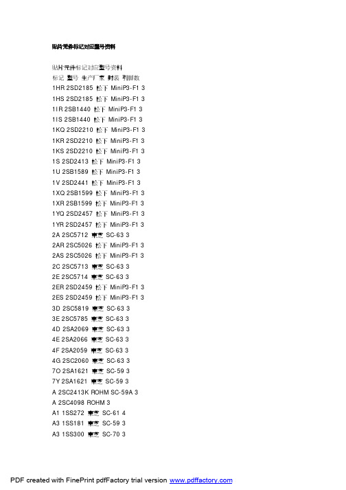
贴片元件标记对应型号资料贴片元件标记对应型号资料标记型号生产厂家封装引脚数1HR 2SD2185 松下MiniP3-F1 3 1HS 2SD2185 松下MiniP3-F1 3 1IR 2SB1440 松下MiniP3-F1 3 1IS 2SB1440 松下MiniP3-F1 3 1KQ 2SD2210 松下MiniP3-F1 3 1KR 2SD2210 松下MiniP3-F1 3 1KS 2SD2210 松下MiniP3-F1 3 1S 2SD2413 松下MiniP3-F1 3 1U 2SB1589 松下MiniP3-F1 3 1V 2SD2441 松下MiniP3-F1 3 1XQ 2SB1599 松下MiniP3-F1 3 1XR 2SB1599 松下MiniP3-F1 3 1YQ 2SD2457 松下MiniP3-F1 3 1YR 2SD2457 松下MiniP3-F1 3 2A 2SC5712 東芝SC-63 32AR 2SC5026 松下MiniP3-F1 3 2AS 2SC5026 松下MiniP3-F1 3 2C 2SC5713 東芝SC-63 32E 2SC5714 東芝SC-63 32ER 2SD2459 松下MiniP3-F1 3 2ES 2SD2459 松下MiniP3-F1 3 3D 2SC5819 東芝SC-63 33E 2SC5785 東芝SC-63 34D 2SA2069 東芝SC-63 34E 2SA2066 東芝SC-63 34F 2SA2059 東芝SC-63 34G 2SC2060 東芝SC-63 37O 2SA1621 東芝SC-59 37Y 2SA1621 東芝SC-59 3A 2SC2413K ROHM SC-59A 3 A 2SC4098 ROHM 3A1 1SS272 東芝SC-61 4A3 1SS181 東芝SC-59 3A3 1SS300 東芝SC-70 3A4 1SS319 東芝SC-61 4A4 1SS383 東芝4A5 1SS384 東芝SOT-343 4A5 1SS391 東芝SC-61 4A6 HN2S01F 東芝SC-74 6A6 HN2S01FU 東芝SC-88 6 A7 1SS402 東芝SOT-343 4A9 1SS294 東芝SC-59 3AL 2SA1971 東芝SC-63 3AL 2SC5307 東芝SC-63 3AN 2SC2532 東芝SC-59 3 AO 2SA2880 東芝SC-63 3 AQ 2SB766 松下MiniP3-F1 3 AR 2SB766 松下MiniP3-F1 3 AS 2SB766 松下MiniP3-F1 3 AU 2SB804 NEC SC-62 3AV 2SB804 NEC SC-62 3AW 2SB804 NEC SC-62 3AY 2SA2880 東芝SC-63 3B 2CS4081 ROHM 3B 2SC2412K ROHM SC-59A 3 B3 1SS184 東芝SC-59 3B3 1SS301 東芝SC-70 3B9 1SS311 東芝SC-59 3B9 1SS397 東芝SC-70 3BD 1SS271 東芝SC-59 3BE 1SV172 東芝BF 1SS268 東芝SC-59 3BG 1SS269 東芝SC-59 3BH 1SS295 東芝SC-59 3BO 2SA1200 東芝SC-63 3 BQ 2SB766A 松下MiniP3-F1 3 BR 2SB766A 松下MiniP3-F1 3 BS 2SB766A 松下MiniP3-F1 3 BU 2SD1005 NEC SC-62 3BU DA228K ROHM SC-59 3 BU DA228U ROHM SC-70 3 BV 2SD1005 NEC SC-62 3BW 2SD1005 NEC SC-62 3BY 2SA1200 東芝SC-63 3C 2SC2411K ROHM SC-59A 3C 2SC4097 ROHM 3C1 1SS352 東芝C1 1SS387 東芝C3 1SS226 東芝SC-59 3C9 1SS307 東芝SC-59 3CEO 2SC3325 東芝SC-59 3 CEY 2SC3325 東芝SC-59 3CG 2SA1163 東芝SC-59 3CK 2SD999 NEC SC-62 3CL 2SD999 NEC SC-62 3CM 2SD999 NEC SC-62 3CO 2SC2881 東芝SC-63 3CO 2SC4209 東芝SC-59 3CQ 2SB767 松下MiniP3-F1 3 CR 2SB767 松下MiniP3-F1 3 CY 2SC2881 東芝SC-63 3CY 2SC4209 東芝SC-59 3D 2SA1037KLN ROHM SC-59A 3 D3 1SS187 東芝SC-59 3DG 2SC2713 東芝SC-59 3DK 2SB798 NEC SC-62 3DL 2SB798 NEC SC-62 3DM 2SB798 NEC SC-62 3DO 2SA1201 東芝SC-63 3DQ 2SB789 松下MiniP3-F1 3 DR 2SB789 松下MiniP3-F1 3 DY 2SA1201 東芝SC-63 3E3 1SS190 東芝SC-59 3EK 2SD1001 NEC SC-62 3EL 2SD1001 NEC SC-62 3EM 2SD1001 NEC SC-62 3EO 2SC2882 東芝SC-63 3EQ 2SB789A 松下MiniP3-F1 3 ER 2SB789A 松下MiniP3-F1 3 EX 2SD2402 NEC SC-62 3EY 2SC2882 東芝SC-63 3EY 2SD2402 NEC SC-62 3EZ 2SD2402 NEC SC-62 3F 2SA1037K ROHM SC-59A 3 F 2SA1576 ROHM 3F3 1SS193 東芝SC-59 3F5 1SS250 東芝SC-59 3F5 1SS370 東芝SC-70 3F5 1SS403 東芝SOD-323 2F9 1SS321 東芝SC-59 3FK 2SB800 NEC SC-62 3FL 2SB800 NEC SC-62 3FM 2SB800 NEC SC-62 3FO 2SA1202 東芝SC-63 3FX 2SB1571 NEC SC-62 3FY 2SA1202 東芝SC-63 3FY 2SB1571 NEC SC-62 3FZ 2SB1571 NEC SC-62 3G3 1SS196 東芝SC-59 3G3 2SA1455K ROHM SC-59A 3 GK 2SD1615 NEC SC-62 3GL 2SD1615 NEC SC-62 3GM 2SD1615 NEC SC-62 3 GO 2SC2883 東芝SC-63 3 GP 2SD1615A NEC SC-62 3 GQ 2SD1615A NEC SC-62 3 GX 2SD2403 NEC SC-62 3GY 2SC2883 東芝SC-63 3GY 2SD2403 NEC SC-62 3GZ 2SD2403 NEC SC-62 3H9 1SS344 東芝SC-59 3HK 2SD1006 NEC SC-62 3HL 2SD1006 NEC SC-62 3HM 2SD1006 NEC SC-62 3 HO 2SA1203 東芝SC-63 3HP 2SD1007 NEC SC-62 3HQ 2SD1007 NEC SC-62 3HR 2SD1007 NEC SC-62 3HR 2SB956 松下MiniP3-F1 3 HS 2SB956 松下MiniP3-F1 3 HX 2SB1572 NEC SC-62 3HY 2SA1203 東芝SC-63 3HY 2SB1572 NEC SC-62 3HZ 2SB1572 NEC SC-62 3I9 1SS336 東芝SC-59 3IK 2SA1463 NEC SC-62 3IL 2SA1463 NEC SC-62 3IO 2SC3515 東芝SC-63 3IQ 2SB1073 松下MiniP3-F1 3 IR 2SC3515 東芝SC-63 3IR 2SB1073 松下MiniP3-F1 3 J 2SC2059K ROHM SC-59A 3J 2SC4099 ROHM 3J9 1SS337 東芝SC-59 3JO 2SA1384 東芝SC-63 3JR 2SK208 東芝SC-59 3JR 2SA1384 東芝SC-63 3K DA221 ROHM SC-75A 3K DA204U ROHM SC-70 3K DA204K ROHM SC-59 3K9 1SS348 東芝SC-59 3KA 2SC4409 東芝SC-63 3KD 2SC4541 東芝SC-63 3KK 2SB805 NEC SC-62 3KL 2SB805 NEC SC-62 3KM 2SB805 NEC SC-62 3KP 2SB806 NEC SC-62 3KQ 2SB806 NEC SC-62 3KR 2SB806 NEC SC-62 3L 2SC2412KLN ROHM SC-59A 3 L9 1SS349 東芝SC-59 3LA 2SA1681 東芝SC-63 3LD 2SA1736 東芝SC-63 3LK 2SD1000 NEC SC-62 3LL 2SD1000 NEC SC-62 3LM 2SD1000 NEC SC-62 3MK 2SB799 NEC SC-62 3 ML 2SB799 NEC SC-62 3 MM 2SB799 NEC SC-62 3 MO 2SC2873 東芝SC-63 3 MY 2SC2873 東芝SC-63 3 N9 1SS372 東芝SC-70 3 N9 1SS374 東芝SC-59 3 NA 2SK1273 NEC SC-62 3 NB 2SK1586 NEC SC-62 3 NC 2SK1485 NEC SC-62 3 ND 2SK1583 NEC SC-62 3 NE 2SK1585 NEC SC-62 3 NF 2SK1587 NEC SC-62 3 NG 2SK1588 NEC SC-62 3 NH 2SK1584 NEC SC-62 3 NI 2SK1586 NEC SC-62 3 NJ 2SK2111 NEC SC-62 3 NK 2SC2780 NEC SC-62 3 NL 2SC2780 NEC SC-62 3 NM 2SC2780 NEC SC-62 3 NO 2SA1213 東芝SC-63 3 NO 2SK1592 NEC SC-62 3 NP 2SK1593 NEC SC-62 3 NQ 2SK1959 NEC SC-62 3 NR 2SK1960 NEC SC-62 3 NS 2SK2109 NEC SC-62 3 NT 2SK2110 NEC SC-62 3 NV 2SK2112 NEC SC-62 3 NW 2SK2159 NEC SC-62 3 NX 2SK2857 NEC SC-62 3 NY 2SA1213 東芝SC-63 3 O9 1SS377 東芝SC-59 3 O9 1SS378 東芝SC-70 3 O9 1SS385 東芝SC-75 3 O9 1SS385F 東芝SC-81 3 OK 2SC3736 NEC SC-62 3 OL 2SC3736 NEC SC-62 3PA 2SJ179 NEC SC-62 3PB 2SJ197 NEC SC-62 3PC 2SJ199 NEC SC-62 3PD 2SJ205 NEC SC-62 3PE 2SJ207 NEC SC-62 3PF 2SJ208 NEC SC-62 3PH 2SJ206 NEC SC-62 3PO 2SC2884 東芝SC-63 3 PO 2SJ212 NEC SC-62 3PP 2SJ213 NEC SC-62 3PQ 2SJ355 NEC SC-62 3PR 2SJ356 NEC SC-62 3PY 2SC2884 東芝SC-63 3 QO 2SC2714 東芝3R12 UMR12N ROHM SC-88 6 R23 2SC3356 Q NEC SC-59 3 R24 2SC3356 R NEC SC-59 3 R25 2SC3356 S NEC SC-59 3 R9 1SS392 東芝SC-59 3R9 1SS393 東芝SC-70 3RQ 2SD1280 松下MiniP3-F1 3 RR 2SD1280 松下MiniP3-F1 3 RS 2SD1280 松下MiniP3-F1 3 S2 1SS315 東芝SC-59 3S9 1SS394 東芝SC-59 3SA 2SC2982 東芝SC-63 3SK 2SC3554 NEC SC-62 3SL 2SC3554 NEC SC-62 3SM 2SC3554 NEC SC-62 3 SO 2SA1162 東芝SC-59 3T9 1SS396 東芝SC-59 3TA 2SA1314 東芝SC-63 3TA 1SV231 東芝1-1E1A 2TB 2SA1314 東芝SC-63 3TC 2SA1314 東芝SC-63 3TE 2SD1702 NEC SC-62 3TF 2SD1702 NEC SC-62 3TL 2SC3617 NEC SC-62 3TM 2SC3617 NEC SC-62 3TQ 2SD1699 NEC SC-62 3TQ 2SD1119 松下MiniP3-F1 3 TR 2SD1699 NEC SC-62 3TR 2SD1119 松下MiniP3-F1 3 UK 2SC3618 NEC SC-62 3UL 2SC3618 NEC SC-62 3UM 2SC3618 NEC SC-62 3VK 2SD1950 NEC SC-62 3VL 2SD1950 NEC SC-62 3VM 2SD1950 NEC SC-62 3 VR 2SD968A 松下MiniP3-F1 3 VS 2SD968A 松下MiniP3-F1 3 VY 2SJ106 東芝SC-59 3W 2SD1383K ROHM SC-59A 3 W3 FMW3 ROHM 5X9 1SS398 東芝SC-59 3XK 2SD1614 NEC SC-62 3XL 2SD1614 NEC SC-62 3XM 2SD1614 NEC SC-62 3 XN 2SD1784 東芝SC-63 3 XR 2SD875 松下MiniP3-F1 3 XS 2SD875 松下MiniP3-F1 3 YB 2SK680A NEC SC-62 3YK 2SB1115 NEC SC-62 3YL 2SB1115 NEC SC-62 3YM 2SB1115 NEC SC-62 3YP 2SB1115A NEC SC-62 3 YQ 2SB1115A NEC SC-62 3 YQ 2SD874A 松下MiniP3-F1 3 YR 2SD874A 松下MiniP3-F1 3 YS 2SD874A 松下MiniP3-F1 3 Z7 2SK2549 東芝SC-63 3Z8 2SJ360 東芝SC-63 3Z9 2SJ465 東芝SC-63 3ZA 2SK2615 東芝SC-63 3ZB 2SK2963 東芝SC-63 3 ZC 2SK2964 東芝SC-63 3 ZD 2SK2992 東芝SC-63 3 ZE 2SJ508 東芝SC-63 3ZF 2SJ511 東芝SC-63 3ZG 2SK3471 東芝SC-63 3 ZK 2SB1114 NEC SC-62 3 ZL 2SB1114 NEC SC-62 3 ZM 2SB1114 NEC SC-62 3 ZO 2SA1182 東芝SC-59 3 ZQ 2SD874 松下MiniP3-F1 3 ZR 2SD874 松下MiniP3-F1 3 ZS 2SD874 松下MiniP3-F1 3 ZX 2SB1628 NEC SC-62 3 ZY 2SB1628 NEC SC-62 3 ZZ 2SB1628 NEC SC-62 3。
贴片二极管26a参数
贴片二极管26a参数
贴片二极管26A是一种高压整流二极管,其参数如下:
1. 最大正向工作电压:2600V
2. 最大反向工作电压:2600V
3. 最大正向工作电流:25A
4. 最大反向工作电流:0.1mA
5. 最大正向压降:2.5V
6. 最大反向漏电流:10uA
7. 工作温度范围:-40℃~ +150℃
8. 封装形式:TO-247AC
这种二极管主要用于高压整流电路中,如高压直流电源、电焊机、电炉等。
其高压、高电流的特点使其能够承受较大的负载,同时其正向压降较小,能够有效地减少功耗。
在实际应用中,需要根据具体的电路要求选择合适的二极管型号,并注意其最大工作电压、最大工作电流等参数,以确保电路的稳定性和可靠性。
FCL 系列产品说明书

Free Chlorine Amperometric SensorsProduct InstructionsParts covered by this product data sheet include:FCL502, FCL505, FCL510, FC72, FCLA-5015, FCLA-5016, FCLA-5017, FCLA-50182.0 pHFree Chlorine (FCL) exists as hypochlorous acid and hypochlorite anion. The acid-base dissociation of FCL has a pKa of approximately 7.5. The FCL sensor responds to hypochlorous acid and hypochlorite anion with different sensitivity. In combination, an increase in pH reduces themea-sured FCL and decrease in pH increases the measured FCL. For the most accurate free chlorine measurement, keep system pH at <6.5.2.1 Chemical InterferencesThe sensor should not be used in water containing surfactants. Monochloramine and ozone are interferences.2.2 FlowTo acheive reproducible measurements, the (FCL) free chlorine require a specified constant flow rate. To avoid complications (such as bubbles), it is best to operate the sensors at a flow rate of 0.2 - 0.6 gpm if using flow cell FC72 or FC70 (old version). Use of a flowmeter is recommended (FM001- See Section 4.1)2.3 PressurePressure is relieved via a small vent hole covered with a silicone sleeve (FIG1). DO NOT REMOVE THE SLEEVE, even when refilling the sensor.Section 1.0Theory of Operation1.0 Free Chlorine DefinedFree Chlorine or "freely active chlorine" is defined as the sum of molecu-lar chlorine (Cl 2), hypochlorous acid (HOCl) and hypochlorite ions (OCl -). Molecular chlorine occurs at pH values <pH4. Hypochlorus acid and hypochlorite ions are in pH dependent equilibrium with one another. Hypochlorous acid is a much stronger disinfecting agent (oxidizer) as compared to hypochlorite ions.1.1 Sensor Operating PrincipleOnly hypochlorous acid (HOCl) diffuses through the membrane be-tween the cathode and sample solution. At the applied potential, only hyphochlorous acid is electrochemically reduced. HOCl is reduced to chloride ion at the gold cathode. At the same time, the silver anode is oxidized to form silver chloride (AgCl). When the concentration of HOCl at the cathode is dramatically decreased by electrochemical reduction, hypochlorite ion will be transformed into hypochlorous acid, and to some extent, by proton transfer. The release of electrons at the cathode and acceptance at the anode creates a current flow, which under constant conditions, is proportional to the free chlorine concen-tration in the medium outside the sensor. The resulting low currentoutput is then conditioned to 4-20mA current or Modbus 485 output by the sensor's onboard electronic circuitry.Section 2.0Factors Influencing the SensorpH CorrectionIf your system is >6.5 pH compensation should be applied to the measured output as follows:K(pH) = a 1 *pH 4 + a 2 *pH 3 + a 3 *pH 2 + a 4 *pH + a 5Where a 1= 0.006817 a 2= -0.000764468 a 3= -2.406291a 4= -23.75 a 5= -63.0508i corrected = [i measured - 4.2mA/k(pH), FCL(ppm) = i corrected /slopeFC72 Flow cellEnsure flow cell is mounted at 45 deg or higher above horizon-tal as shown in FIG 2B.4.1 Flow MeterTo control flow to the flow cell, a flow meter is recommended.Sensorex supplies model FM001 for this purpose. The FM001provides flow control from 0.1 to 1.0 GPM (0.5 to 4.0 LPM) with94% accuracy.FIG. 3SECTION 5.0Sensor Installation5.0 Sensor Installation into Flow Cella)First install threaded fitting onto sensor body (remove fitting if pre-installed in flow cell) FIG 2d b)Install snap-ring into groove on sensor bodyc)Next, slide o-ring onto body of sensor until it reaches bottom of threaded fitting.d) Thread sensor assembly into top of flow cell as shown in FIG 2c.e) Turn on flow and verify the flow through the Flow Cell is at least 0.2 gpm (45 liters/hour and no more than 0.6gpm (135 liters/hour).6.0 Electrical InstallationThe sensor is supplied in 2 output types, 4-20mA or Modbus 485.Ou tput of 4 mA in air and 20 mA at the top range of free chlorine output (0-2ppm, 0-5ppm and 0-10ppm) or Modbus 485.NOTE: The supply voltage to the Sensor must be 12-24 V DC with minimum of 250 mA. Maximum load is 1 Watt. The sensor has 2 wires, red (+), black (-). Attach the red wire to the power supply positive ter-minal (+) and the black wire to the PLC or DVM positive (+) terminal. Connect a wire (customer supplied) from the power suppy negative (-) and the PLC or DVM (-). See FIG 3. See FIG3A for Modbus connections.SECTION 6.0Electrical InstallationSECTION 7.0Sensor Conditioning7.0 Sensor ConditioningThe sensor requires conditioning prior to generating stable values.a) For new Sensors, connect the sensor to power and allow to run overnight (at least 12 hours) before calibration.b) If the Sensor will be un-powered for two hours or more, run for two hours prior to use.c) If the Sensor's flow will be off for one hour or less, run the sensor for at least one hour prior to recalibration.d) After membrane/electrolyte replacement, allow the Sensor to run powered overnight (at least 12 hours) before calibration .4.1.1 Install the flow meter and flow cell as shown in FIG 2C.Follow the diagram so that the incoming water is attached to the bottom of the flow meter (where flow adjustment knob is located).FIG. 7FIG. 6c) Adjust span/slope at PLC/4-20mA devic e for 4-20mA models only.d) Repeat this slope calibration one day after sensor is initially installed.e) Repeat the slope calibration weekly.Section 9.0Sensor Storage9.0 StorageStore sensor at 5o C - 50o C only and maximum humidity of 95% non-condensing.a) Short Term Storage (one week or less): Store in Flow cell with water to prevent the probe from drying out.b) Intermediate Term (one week to one month): Store with cap on sen-sor in a beaker with water to keep membrane wet.c) Long Term (one month or longer): Remove Membrane Cap and store cap completely immersed in tap water. Remove fill solution and pour down drain.Note: Electrolyte shelf life is one year from date of mfg (see bottle).Section 10.0Sensor Maintenance10.0 Membrane Cap ReplacementIf membrane replacement is required, a new cap with preinstalled mem-brane must be used. Two caps and 2 bottles of refill solution are shipped with each sensor. Additional caps are ordered as FCLA-5016, and refill solution as FCLA-5015.To change membrane cap:a) Turn sensor upside down with cap facing upward.b) Rotate cap counter-clockwise to remove (SEE FIG 5).c) Place needle tip on syringe as shown in FIG 6d) Remove solution from bottle with needle and syringe (FIG 7)e) Fill sensor body with electrolyte using needle and bottle of refill solution until it flows out of the holes near the cathode(SEE FIG 8).f) Add a few drops of electrolyte to the membrane cap (FIG 9)g) Install new membrane cap by threading cap onto sensor rotating cap clockwise (Opposite of FIG 5).DO NOT TOUCH THE CATHODE DURING THIS PROCESS SINCE IT CAN BE DAMAGED.F C LA -7000F C L A -7000FIG. 3A3. Pressure fluctuation in sample lineFCLA-7000Free Chlorine /Chlorine Dioxide Colorimeter-eXact 7+, requires CLDA-7001 strips5.58"(142mm)3.82"(97mm)2.25"(57mm)2.25"(57mm)4.61"(117mm)10.19"(259mm)3.78"(96mm)GPM LPMstay this way – do not put a flat on the cathode.7))Check tbrighter and shinier than before (FIG. 5) the operation using the abrasive paper. 8))as the gold surface can be easily damaged.membrane pocket (FIG. 7)the sensor.cap with a towel.10.0DAMAGE TO THE GOLD ELECTRODE.* *。
CM2系列、CM2Z系列塑料外壳式断路器
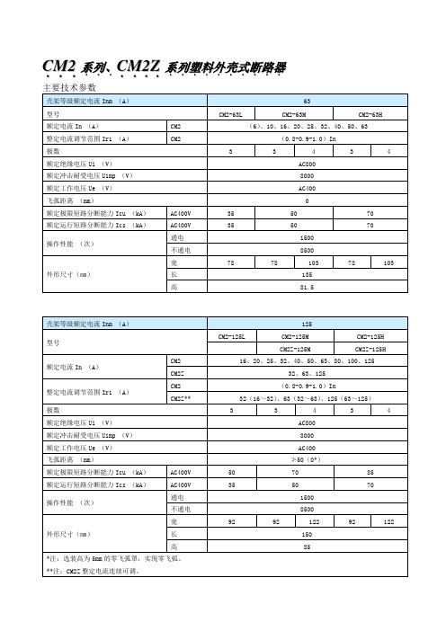
主要技术参数
壳架等级额定电流Inm(A)
63
型号
CM2-63L
CM2-63M
CM2-63H
额定电流In(A)
CM2
(6)、10、16、20、25、32、40、50、63
整定电流调节范围Ir1(A)
CM2
(0.8-0.9-1.0)In
极数
3
3
4
3
4
额定绝缘电压Ui(V)
8000
额定工作电压Ue(V)
AC400
飞弧距离(mm)
≯100(0*)
额定极限短路分断能力Icu(kA)
AC400V
50
70
100
额定运行短路分断能力Ics(kA)
AC400V
50
70
75
操作性能(次)
通电
1000
不通电
4000
外形尺寸(mm)
宽
182
182
240
182
240
长
270
高
110
*注:选装高为11.5mm的零飞弧罩,实现零飞弧。
AC400
飞弧距离(mm)
≯50(0*)
额定极限短路分断能力Icu(kA)
AC400V
50
70
85
额定运行短路分断能力Ics(kA)
AC400V
35
50
70
操作性能(次)
通电
1000
不通电
7000
外形尺寸(㎜)
宽
107
107
142
107
142
长
165
高
85
*注:选装高为6mm的零飞弧罩,实现零飞弧。
26类氟橡胶技术_刘伯南

26 类氟橡胶生胶体系可分两大类,即二元共聚
的 26 胶和三元共聚的 246 胶,每一类又可按门尼黏
度分为高、中、低不同门尼黏度的氟橡胶品种,每一
个氟橡胶品种又可按分子量分布分为不同的品级,
而分子量分布可以是单峰宽分布和双峰宽分布,可
有不同的分布指数。
就加工而言,高门尼黏度氟橡胶只适用于模压
制品的加工,当要求制品耐油或较高的机械强度时,
( 2) 硫化曲线解读 通常从硫化曲线上可看出胶料的硫化特性,即 起始黏度、焦烧时间、正硫化时间、交联度、硫化平坦 性、返原性,从而判断硫化配方的适用性和应取的加 工条件,其中焦烧时间和正硫化时间最为重要。 1) Mn———MindNm 最小转矩,其大小反映了混 炼胶料加工充模流动性的优劣,决定胶料是用于压 出成型还是模压成型和能否用于形状复杂制品的加 工; 2) Tn———达到最低黏度的对应时间,衡量加工 制品时控制质量的时间是否足够; 3) TS2 ———焦 烧 时 间 ( T10 ) { 转 矩 达 到[Mn + ( Mm - Mn) × 10%]所需时间} ; 焦烧是指胶料产生早期硫化的现象。焦烧的产 生将使胶料流动性降低,不能继续进行形变加工或 造成制品的缺陷。通常设计的配方,必须在规定的 硫化温度下硫化时间最短,而在加工( 制备混炼胶 等) 温度下焦烧时间最长。一般设计的硫化配方焦 烧时间在 1. 5 ~ 2. 0 min 范围内,以便降低能耗和提 高生产率; 4) 硫化速度和正硫化时间 T90 硫化速度以硫化指 数———硫 化 曲 线 上升阶段 的斜率表示,斜率越大,硫化速度越快; 正硫化时间 以 T90 ———转矩达到[Mn + ( Mm - Mn) × 90%]所需 时间为正硫化时间,一般设计的硫化配方控制 T90 在 2. 5 ~ 3. 5 min,过快会使制品中存在应力,使制品容 易变形,需降低活性促进剂用量; 过长能耗高、生产 效率低; 5) Mm———MaxdNm 最大转矩,反映硫化胶的最 大交联度。如果 Mm 较小,说明硫化剂用量太少或 硫化不完全,需要调整硫化配方。Mm 过大,说明硬 度和定伸强度均太高,可减少硫化剂用量; 6) 硫化平坦性。当转矩达到最大后,有时转矩 不变而曲线变得平坦,有效的硫化体系在硫化曲线 上基本上是平坦的,说明硫化体系形成的硫化键的 键能很高,耐热性好,耐热老化性能稳定,在高温下
禧玛诺SHIMANO产品各种型号字母缩写解析
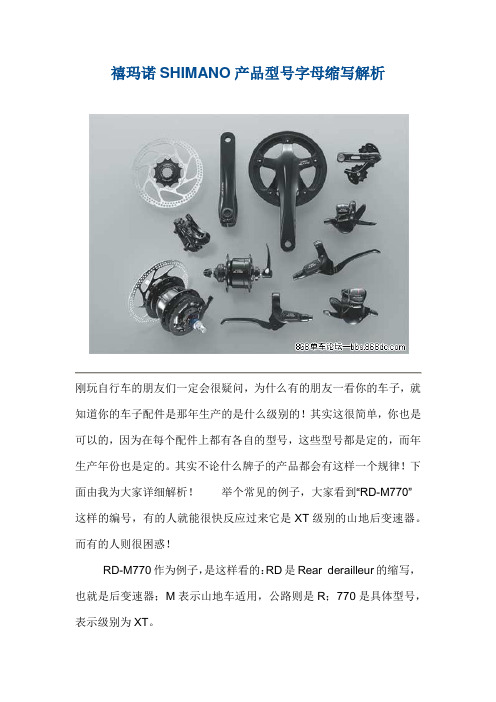
禧玛诺SHIMANO产品型号字母缩写解析刚玩自行车的朋友们一定会很疑问,为什么有的朋友一看你的车子,就知道你的车子配件是那年生产的是什么级别的!其实这很简单,你也是可以的,因为在每个配件上都有各自的型号,这些型号都是定的,而年生产年份也是定的。
其实不论什么牌子的产品都会有这样一个规律!下面由我为大家详细解析!举个常见的例子,大家看到“RD-M770”这样的编号,有的人就能很快反应过来它是XT级别的山地后变速器。
而有的人则很困惑!RD-M770作为例子,是这样看的:RD是Rear derailleur的缩写,也就是后变速器;M表示山地车适用,公路则是R;770是具体型号,表示级别为XT。
SHIMANO生产的零部件主要有:变速杆,前后拨,牙盘中轴,飞轮,链条,刹车,花鼓。
下面是各自缩写:SL指拨,ST双控,FC牙盘,RD后拨,FD前拨,CS飞轮,HB /FH前后花鼓,BR刹车(包括线刹和油碟),BL刹车手柄(包括线刹和油碟)。
明白这些后,看到一个零件的编号,通过它的前两个字母,你可以立刻明白那是个刹车还是后拨还是牙盘。
然后是RD-M770里面770这个编号的含义。
这一个数字表示了零件等级,零件兼容性和零件款式年代。
先介绍最直观的零件等级,我们常常听说的。
2000后山地产品中依价格由低到高排列:TOURNEY,ALTUS,ACERA,ALIVIO,DEO RE,DEORE LX,HONE,DEORE XT,SAINT,XTR。
补充说明:HONE和SAINT为极限车套件,用于攀爬和速降,一般较少见;现在推出了一个新级别叫SLX,用来代替原先DEORE LX 和HONE的位置,新的DEORE LX则成为了单独的旅行车产品。
770的第一位“7”代表等级,任何7**都表示XT级别。
同样的:XT R是9**,SAINT是8**,HONE和SLX是6**,LX和DEORE是5**,ALIVIO是4**,ACERA是3**。
LXM26参考手册

Lexium 26 基础培训教材~220V 含义R 单相或三相220VAC驱动器主电源输入STL1 单相220VAC驱动器控制电源输入L2Motor 含义PE 电机地线U 电机U相V 电机V相W 电机W相Resistor 含义PBe 制动电阻公共端PBi 内部制动电阻PA/+ 外部制动电阻CN2 含义E 电机编码器CN3 含义Modbus 调试及Modbus接口CN1 含义I/O 各数字量/模拟量/脉冲信号输入输出接口CN1 信号含义Mode35 PULL HI_S 开集电极方向信号正P36 /SIGN 线驱动方向信号正P37 SIGN 方向信号负P39 PULL HI_P 开集电极脉冲信号正P43 /PULSE 线驱动脉冲信号正P41 PULSE 脉冲信号负P46 HSIGN 高速脉冲方向信号正P40 /HSIGN 高速脉冲方向信号负P38 HPULSE 高速脉冲脉冲信号正P29 /HPULSE 高速脉冲脉冲信号负P42 V_REF 速度参考模拟电压Vz44 GND 速度参考模拟电压地Vz18 T_REF 扭矩参考模拟电压Tz19 GND 扭矩参考模拟电压地Tz CN1 信号含义Mode 17 VDD 内部24V电源24V+ ALL 45/47/49 COM- 内部24V电源0V ALL 11 COM+ 输入信号公共端ALL09 DI1- 数字输入1 ALL10 DI2- 数字输入2 ALL 34 DI3- 数字输入3 ALL 08 DI4- 数字输入4 ALL 33 DI5- 数字输入5 ALL 32 DI6- 数字输入6 ALL 31 DI7- 数字输入7 ALL 30 DI8- 数字输入8 ALLCN1 信号含义Mode 07 DO1+ 数字输出1正ALL 06 DO1- 数字输出1负ALL 05 DO2+ 数字输出2正ALL 04 DO2- 数字输出2负ALL 03 DO3+ 数字输出3正ALL 02 DO3- 数字输出3负ALL 01 DO4+ 数字输出4正ALL 26 DO4- 数字输出4负ALL 28 DO5+ 数字输出5正ALL 27 DO5- 数字输出5负ALL CN1 信号含义Mode21 OA 模拟编码器输出A ALL22 /OA 模拟编码器输出/A ALL 25 OB 模拟编码器输出B ALL 23 /OB 模拟编码器输出/B ALL 50 OZ 模拟编码器输出Z ALL 24 /OZ 模拟编码器输出/Z ALL2.1PT 模式PT (Pulse Train) Mode -- 脉冲串控制模式(P1-01最后两位设为00): 在PT运行模式中,驱动器与一组主输入端输入的脉冲串同步。
2SC2620中文资料

2SC2620Silicon NPN Epitaxial PlanarApplicationVHF amplifier, Local oscillatorOutline2SC26202Absolute Maximum Ratings (Ta = 25°C)ItemSymbol Ratings Unit Collector to base voltage V CBO 30V Collector to emitter voltage V CEO 20V Emitter to base voltage V EBO 4V Collector currentI C 20mA Collector power dissipation P C 100mW Junction temperature Tj 150°C Storage temperatureTstg–55 to +150°CElectrical Characteristics (Ta = 25°C)ItemSymbol Min Typ Max Unit Test conditions Collector to base breakdown voltageV (BR)CBO30——V I C = 10 µA, I E = 0Collector to emitter breakdown voltageV (BR)CEO 20——V I C = 1 mA, R BE = ∞Emitter to base breakdown voltageV (BR)EBO 4——V I E = 10 µA, I C = 0Collector cutoff current I CBO ——0.5µA V CB = 10 V, I C = 0Emitter cutoff current I EBO ——0.5µAV EB = 2 V, I C = 0DC current transfer ratio h FE *160—200V CE = 6 V, I C = 1 mA Collector to emitter saturation voltageV CE(sat)—0.17—V I C = 20 mA, I B = 4 mA Base to emitter voltage V BE —0.72—V V CE = 6 mA, I C = 1 mA Gain bandwidth product f T —940—MHz V CE = 6 V, I C = 5 mA Collector output capacitance Cob—0.9—pF V CB = 10 V, I E = 0, f = 1 MHzNote: 1.The 2SC2620 is grouped by h FE as follows.Grade B C Mark QB QC h FE60 to 120100 to 200See characteristic curves of 2SC535.2SC26203Hitachi CodeJEDECEIAJWeight (reference value)MPAK—Conforms0.011 gUnit: mm元器件交易网Cautions1.Hitachi neither warrants nor grants licenses of any rights of Hitachi’s or any third party’s patent,copyright, trademark, or other intellectual property rights for information contained in this document.Hitachi bears no responsibility for problems that may arise with third party’s rights, includingintellectual property rights, in connection with use of the information contained in this document.2.Products and product specifications may be subject to change without notice. Confirm that you have received the latest product standards or specifications before final design, purchase or use.3.Hitachi makes every attempt to ensure that its products are of high quality and reliability. However,contact Hitachi’s sales office before using the product in an application that demands especially high quality and reliability or where its failure or malfunction may directly threaten human life or cause risk of bodily injury, such as aerospace, aeronautics, nuclear power, combustion control, transportation,traffic, safety equipment or medical equipment for life support.4.Design your application so that the product is used within the ranges guaranteed by Hitachi particularly for maximum rating, operating supply voltage range, heat radiation characteristics, installationconditions and other characteristics. Hitachi bears no responsibility for failure or damage when used beyond the guaranteed ranges. Even within the guaranteed ranges, consider normally foreseeable failure rates or failure modes in semiconductor devices and employ systemic measures such as fail-safes, so that the equipment incorporating Hitachi product does not cause bodily injury, fire or other consequential damage due to operation of the Hitachi product.5.This product is not designed to be radiation resistant.6.No one is permitted to reproduce or duplicate, in any form, the whole or part of this document without written approval from Hitachi.7.Contact Hitachi’s sales office for any questions regarding this document or Hitachi semiconductor products.Hitachi, Ltd.Semiconductor & Integrated Circuits.Nippon Bldg., 2-6-2, Ohte-machi, Chiyoda-ku, Tokyo 100-0004, Japan Tel: Tokyo (03) 3270-2111 Fax: (03) 3270-5109Copyright ' Hitachi, Ltd., 1999. All rights reserved. Printed in Japan.Hitachi Asia Pte. Ltd.16 Collyer Quay #20-00Hitachi TowerSingapore 049318Tel: 535-2100Fax: 535-1533URLNorthAmerica : http:/Europe : /hel/ecg Asia (Singapore): .sg/grp3/sicd/index.htm Asia (Taiwan): /E/Product/SICD_Frame.htm Asia (HongKong): /eng/bo/grp3/index.htm Japan : http://www.hitachi.co.jp/Sicd/indx.htmHitachi Asia Ltd.Taipei Branch Office3F, Hung Kuo Building. No.167, Tun-Hwa North Road, Taipei (105)Tel: <886> (2) 2718-3666Fax: <886> (2) 2718-8180Hitachi Asia (Hong Kong) Ltd.Group III (Electronic Components)7/F., North Tower, World Finance Centre,Harbour City, Canton Road, Tsim Sha Tsui,Kowloon, Hong Kong Tel: <852> (2) 735 9218Fax: <852> (2) 730 0281 Telex: 40815 HITEC HXHitachi Europe Ltd.Electronic Components Group.Whitebrook ParkLower Cookham Road MaidenheadBerkshire SL6 8YA, United Kingdom Tel: <44> (1628) 585000Fax: <44> (1628) 778322Hitachi Europe GmbHElectronic components Group Dornacher Stra§e 3D-85622 Feldkirchen, Munich GermanyTel: <49> (89) 9 9180-0Fax: <49> (89) 9 29 30 00Hitachi Semiconductor (America) Inc.179 East Tasman Drive,San Jose,CA 95134 Tel: <1> (408) 433-1990Fax: <1>(408) 433-0223For further information write to:。
台虹产品代号说明(常规、2LP、无卤素_
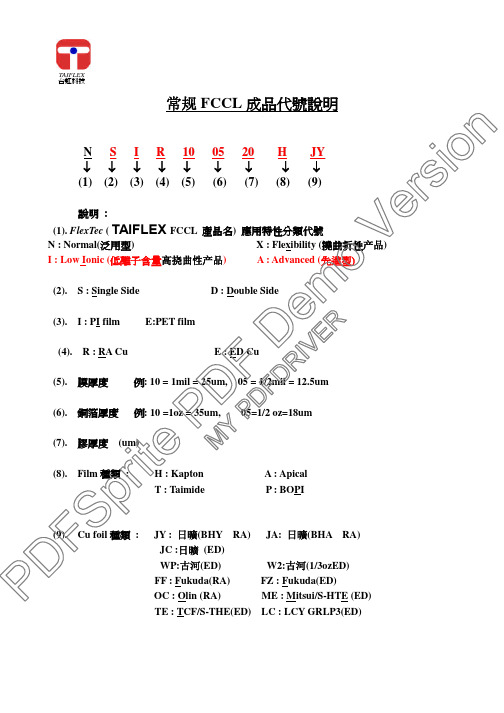
TAIFLEX台虹科技常规FCCL 成品代號說明N S I R 100520J Y ↓↓↓↓↓↓↓↓↓(1) (2) (3) (4) (5) (6) (7) (8) (9)說明:(1). FlexTec ( TAIFLEX FCCL 產品名)應用特性分類代號N : Normal(泛用型) X : Flexibility (撓曲折性产品) I : Low Ionic (低離子含量高挠曲性产品) A : Advanced (先進型)(2). S : Single SideD : Double Side(3). I : PI film E:PET film(4). R : RA Cu E : ED Cu(5). 膜厚度例: 10 = 1mil = 25um, 05=1/2mil =12.5um(6). 銅箔厚度例: 10 =1oz = 35um, 05=1/2 oz=18um(7). 膠厚度 (um)(8).Film 種類 : H : Kapton A : ApicalT : TaimideP : BOPI(9). Cu foil 種類 :JY : 日曠(BHY RA) JA: 日曠(BHA RA) JC :日曠 (ED)WP:古河(ED) W2:古河(1/3ozED)FF : Fukuda(RA)FZ : Fukuda(ED)OC : Olin (RA)ME : Mitsui/S-HTE (ED)TE : TCF/S-THE(ED) LC : LCY GRLP3(ED)P D F Sp r i t eP D F D e moVe rs io nM YP D F DRI VE RTAIFLEX台虹科技常规COVERLAY 成品代號說明F D 1025L 3↓↓↓↓↓↓(1) (2) (3) (4) (5) (6) 說明:(1). Flex Bond : ( TAIFLEX Coverlay 產品名)(2). D :常规挠曲性胶(搭配N 、及X 型基材使用)I :低離子量的透明柔软型膠(搭配低離子含量高挠曲性产品使用)(3). Film 厚度例: 10 =1 mil = 25um, 05 =1/2 mil =12.5um(4).膠厚度 um(5). PI Film 種類代號 :H : KaptonT : TaimideA : Apical P : BOPI(6). 貼合材代號DF De moV er s i o n M YP DF DRI VERTAIFLEX台虹科技常规補強板成品代號說明F R 8025↓↓↓↓(1) (2) (3) (4) 說明:(1). Flex Bond : ( TAIFLEX Coverlay 產品名)(2). R :常规Reinforce(3). 複合基材總厚度例: 80 = 8 mil = 200um(4).膠厚度 um 例: 25 = 25 umP D F Sp r i t eP D F D e moVe rs i o nM YP DF DRI VE RTAIFLEX台虹科技常规複合板成品代號說明M I A 5025↓↓↓↓↓ (1) (2) (3) (4) (5) 說明:(1). M : 表複合基材 (Material)(2).基材類別 C : Copper Foil 銅箔基材, I : PI 基材(3). PI Film 種類代號 :H : Kapton H A : Apical AH N : Apical NPIT : Taimide P : BOPI(4). 複合基材總厚度例: 50 = 5 mil = 125 um(5). 膠厚度(um)例: 25 = 25 umP D F Sp r i t eP D F D e moVe rs i o nM YP DF DRI VE RTAIFLEX台虹科技常规純膠成品代號說明B S 10↓↓↓(1) (2) (3) 說明 :(1). BS : Bonding Sheet( TAIFLEX 純膠產品名)(2). 膠厚度 um 例: 10 = 10 um(3). 貼合材品名代號DF De moV er s i o n M YP DF DRI VERTAIFLEX台虹科技无胶基材成品代码说明2LP S R 1005JY↓↓↓↓↓↓(1) (2) (3) (4)(5) (6)說明:(1).2LP 2Layer CCL 代號產品名(2).S : Single SideD : Double Side(3) R: Wrought copper foil (壓延銅箔) E: Deposition copper foil(4).PI 膜厚度例: 10 = 1mil = 25um, 05=1/2mil =12.5um(5).銅箔厚度例: 10 =1oz = 35um 05=1/2oz= 18um(6).Cu foil 種類 :JY : JE / BHY (RA) JA: 日曠(BHA RA)JC : JE/ JTC (ED) WP:古河(ED) W2:古河(1/3ozED)FF : Fukuda/ RCF (RA) FZ :Fukuda/CF-T9FZ-UH(ED)OC : Olin (RA) ME : Mitsui (ED)TE : TCF/(ED)LC : LCY (ED) UP: 日本電解 USLP-R2P D F Sp r i t eP D F D e moVe rs i o nM YP DF DRI VE RTAIFLEX台虹科技Halogen Free 產品FCCL 成品編號T H K S 100520J Y ↓↓↓↓↓↓↓↓(1) (2) (3) (4) (5) (6) (7) (8) 說明:(1)T → CCL 代號產品名(2)H → Halogen free(3)PI Film 類別 : K → Kapton film ; A → Apical film(kaneka); T → Taimide ;P → BOPI(4)S : Single Side D : Double Side(5)PI 膜厚度例: 10 = 1mil = 25um, 05=1/2mil =12.5um(6)銅箔厚度例: 10 =1oz = 35um, 05=1/2oz=18um(7)膠厚度 (um)(8). Cu foil 種類 :JY : 日曠(RA) JC :日曠 (ED)FF : Fukuda(RA)FZ : Fukuda(ED)OC : Olin (RA)ME : Mitsui/S-HTE (ED)TE : TCF/S-THE(ED) LC : LCY GRLP3(ED)P D F Sp r i t eP D F D e moVe rs i o nM YP DF DRI VE RTAIFLEX台虹科技Halogen Free 產品Coverlay 成品編號F H K 25L ↓↓↓↓↓↓(1) (2) (3) (4) (5) (6) 說明:(1). F → Coverlay 產品名(2). H → Halogen free(3)PI Film 類別 : K → Kapton film ;A → Apical film(kaneka);T → Taimide ; P → BOPI(4). PI Film 厚度例: 10 =1 mil = 25um, 05 =1/2 mil =12.5um(5).膠厚度 um(6). 貼合材品名代號 :P D F Sp r i t eP D F D e moVe rs i o nM YP DF DRI VE RTAIFLEX台虹科技Halogen Free 產品Bonding Sheet(純膠)成品編號B H 10↓↓↓(1) (2) (3)說明 :(1). B → Bonding Sheet(純膠產品名)(2). H → Halogen free(3). 膠厚度 um 例: 10 = 10 umP D F Sp r i t eP D F D e moVe rs i o nM YP DF DRI VE RTAIFLEX台虹科技Halogen Free 產品Reinforcement (補強板)成品編號R H A 8025↓↓↓↓↓(1) (2) (3) (4) (5) 說明:(1)R →Reinforcement(補強板產品名)(2)H → Halogen free(3)PI Film 類別 : K → Kapton film ; A → Apical film kaneka); T → Taimide ;P → BOPI(4)複合基材總厚度例: 80 = 8 mil = 200um(5).接著劑膠厚度 um例: 25 = 25 umP D F Sp r i t eP D F D e moVe rs i o nM YP DF DRI VE RTAIFLEX台虹科技Halogen Free 產品複合板成品編號M H A 5025↓↓↓↓↓(1) (2) (3) (4) (5)說明:(1). M : 表複合基材 (Material)(2).H → Halogen free(3). PI Film 類別 : K → Kapton film A → Apical film(kaneka) T → TaimideP → BOPI (4). 複合基材總厚度例: 50 = 5 mil = 125 um (5). 膠厚度(um)例: 25 = 25 um P D F S p r i t e P D F D e m o V e r s i o n M Y P D F D R I V E R。
EEA-PAM-523-D-32中文资料
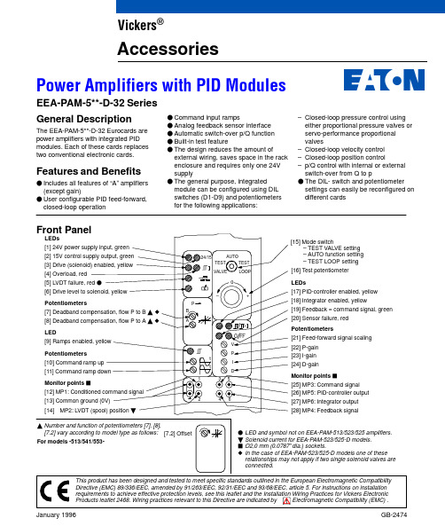
F LED and symbol not on EEA-PAM-513/523/525 amplifiers.B Solenoid current for EEA-PAM-523/525-D models.J Ø2,0 mm (0.0787I dia.) sockets.z In the case of EEA-PAM-523/525-D models one of these relationships may not apply if two single solenoid valves are connected.[14]Monitor points [4] Overload, red[15] Mode switch– TEST VALVE setting – AUTO function setting – TEST LOOP setting [16] T est potentiometer[17] PID-controller enabled, yellow [19] Feedback = command signal, green [21] Feed-forward signal scaling[23] I-gain [18] Integrator enabled, yellow[20] Sensor failure, red [22] P-gain [24] D-gainPotentiometersLEDsPotentiometersLEDPotentiometersLEDs[25] MP3: Command signal [27] MP6: Integrator output [26] MP5: PID-controller output Monitor points J[28] MP4: Feedback signalJanuary 1996GB-2474EEA-PAM-5**-D-32 Series General DescriptionThe EEA-PAM-5**-D-32 Eurocards are power amplifiers with integrated PID modules. Each of these cards replaces two conventional electronic cards.Features and BenefitsF Includes all features of “A” amplifiers (except gain)F User configurable PID feed-forward,closed-loop operationF Command input rampsF Analog feedback sensor interface F Automatic switch-over p/Q function F Built-in test featureF The design reduces the amount ofexternal wiring, saves space in the rack enclosure and requires only one 24V supplyF The general purpose, integrated module can be configured using DIL switches (D1-D9) and potentiometers for the following applications:–Closed-loop pressure control using either proportional pressure valves or servo-performance proportional valves–Closed-loop velocity control –Closed-loop position control–p/Q control with internal or external switch-over from Q to pF The DIL- switch and potentiometer settings can easily be reconfigured on different cardsVickers ®AccessoriesPower Amplifiers with PID ModulesModel CodesAmplifier model For valvesEEA-PAM-513-D-32 EEA-PAM-523-D-32 EEA-PAM-525-D-32 EEA-PAM-533-D-32 EEA-PAM-535-D-32 EEA-PAM-541-D-32 EEA-PAM-553-D-32 EEA-PAM-561-D-32 EEA-PAM-568-D-32 EEA-PAM-571-D-32 EEA-PAM-581-D-32KCG-3, KCG-6/8KX(C)G-6/8K*G4V-3, KDG5V-5/7/8K*G4V-5KF*G4V-3KF*G4V-5KHDG5V-5/7/8 with zerolapped mainspool KSDG4V-3KFDG5V-5/7KFDG5V-8CVU-**-EFP1KHDG5V-5/7/8}With type “H”coils onlyOperating DataJ The demand signal should have the same voltage range as the sensor feedback, Continued on next pagei.e. 0 to 10V, or "10V.Continued on next page3Warning: Electromagnetic Compatibility (EMC)It is necessary to ensure that the valve is wired up in accordance with the connection arrangements shown in this leaflet. For effective protection, the user ’s electrical cabinet, the valve subplate or manifold and the cable screens should be connected to efficient earth (ground) points. The metal 7-pin connector part no. 934939 should be used for the integral amplifier.In all cases, both valve and cable should be kept as far away as possible from any source of electromagnetic radiation such as cables carrying heavy current, relays and certain kinds of portable radio transmitters, etc. Difficult environments could mean that extra screening may benecessary to avoid the interference.4J Located on PID module.Y All amplifiers except EEA-PAM-523/525 models, in which solenoid current is monitored.Circuit and Connections5Solenoid and LVDT Connections for Proportional Valves6Amplifier typeSolenoid with LVDT and/or for Solenoidwithout LVDT,or on pilot Pilot-stage LVDT,(black plug):Main-stage LVDT,(gray plug):and/or for flow P to B or on pilot valve Pin 1Pin 2Pin 3Pin 4Pin 1Pin 2Pin 3Pin 4EEA-PAM-513-D-32EEA-PAM-523-D-32EEA-PAM-525-D-32EEA-PAM-533-D-32EEA-PAM-535-D-32EEA-PAM-541-D-32EEA-PAM-553-D-32EEA-PAM-561-D-32EEA-PAM-568-D-32EEA-PAM-571-D-32EEA-PAM-581-D-32b26/b28b26/b28b26/b28b26/b28b26/b28–––––––z26/z28z26/z28z26/z28z26/z28z26/z28z26/z28z26/z28z26/z28z26/z28z26/z28–––––z14––––z14–––––z22––––z22–––––z16––––z16Not connected Not connected Not connected Not connected Not connected Not connected Not connected Not connected Not connected Not connected Not connected–––b14b14b14b14b14b14b14b14–––z22z22z22z22z22z22z22z22–––b16b16b16b16b16b16b16b16Not connected Not connected Not connected Not connected Not connected Not connected Not connected Not connected Not connected Not connected Not connected3rd angle projectionPlug-in Unit of 3U height, to IEC 297Installation Dimensions in mm (inches)Application NotesFactory settingON OFFLocation of User Features on PID ModuleI-gainFeed-forward gain7DIL SwitchesThe controller is configured for theapplication using DIL switches, located on the board.The DIL switch operates as follows:Switch ONOFFD1:For sensors with 4 to 20 mA output For sensors with "10V or 20 mA outputs D2:P-gain 2 to 50P-gain 0,1 to 2D6:One-sided limitation of the integrator output. (Only useful for proportional pressure and proportional throttle valves.)No limitations of integrator outputD7:Inverts the controller output signal Non-inverted signal D8:For sensors with 4 to 20 mA output For sensors with "10V or20 mA outputs D9:Ramp signal not inverted Ramp signal inverted D10:Not used–For p/Q control with automaticswitch-over, connect d16 to z2 (+10V).The flow command signal (Q) is applied to the feed-forward input, d8, and thedesired pressure setpoint voltage applied to a command signal input (b6/8/10 or z6/8/10). The pressure feedback sensor is connected to the sensor input d2, or d6as required.The pressure control loop will override the flow command to limit the pressure to the level determined by the pressure setpoint voltage. Adjust P , I and D gains for best performance.The switches D3, D4 and D5 belong together. They limit the I output volts between 100% (10V) and 5% (0,5V) as follows:D3D4D5l-limit ON ON ON ON OFF OFF OFF OFFON ON OFF OFF ON ON OFF OFFON OFF ON OFF ON OFF ON OFF100%50%35%25%5,9%5,8%5,3%5,0%Reconfiguration of Controller ParametersOnce the controller parameters have been optimized and set, they can be measured by means of an ohmmeter.This allows easy reconfiguration of the controller on different cards for use as spare parts or on standard machine series.Four test points are located on thePID-module for this purpose, see diagram for locations. The resistance between the appropriate test point and ground (at the front panel monitor point) determines the controller parameters:P = P-gain I = I-gain D =D-gainV =Feed-forward gainOperation of the Integrated Test Mode The basic operation of the hydraulic actuator can be tested by using the 3-position mode switch mounted on the front panel. To select different modes the toggle switch must be lifted slightly before turning it to a new position.Caution:Before setting the mode switch to either “Test valve” or “Test loop” make sure the test potentiometer is set to “0”.Otherwise sudden movements of the actuator may occur.The mode switch has three positions:AUTOThe controller operates in closed-loop mode, using the external command signal. The test potentiometer is disconnected.TEST VALVEAn open-loop command signal for the valve comes directly from thepotentiometer. The external input signal is disconnected. The hydraulic part of the system may be tested in this configuration.TEST LOOPThe closed-loop command signal for the PID-controller comes directly from the potentiometer. The external signal input is disconnected. This configuration allows for verification of the valvepolarity and the control parameters.T est potentiometer on front panelsignalPrinted in U.S.A.E Eaton Hydraulics, Incorporated, 2000 All Rights Reserved。
PA26中文资料

MICROTECHNOLOGY
POWER DUAL OPERATIONAL AMPLIFIERS
PA21/25/26 • PA21A/25A
(800) 546-APEX (800) 546-2739
FEATURES
R2
R3
9K +28V
10K R4
R1
10K
–
–
5K
A
M
B
+
+
1/2 PA21
1/2 PA21
COMMAND INPUT 0/10V
+28V
R5 10K
R6 10K
FIGURE 1: BIDIRECTIONAL SPEED CONTROL FROM A SINGLE SUPPLY
The amplifiers are especially well-suited for this application. The extended common mode range allows command inputs as low as 0V. Its superior output swing abilities let it drive within 2V of supply at an output current of 2A. This means that a command input that ranges from 0V to 10V will drive a 24V motor from full scale CCW to full scale CW at up to ±2A. A single power op amp with an output swing capability of Vs –6 would require ±30V supplies and would be required to swing 48V p-p at twice the speed to deliver an equivalent drive.
byv26c系列二极管资料
a
MAM047
Fig.1 Simplified outline (SOD57) and symbol.
LIMITING VALUES In accordance with the Absolute Maximum Rating System (IEC 134).
SYMBOL
PARAMETER
CONDITIONS
1996 May 30
4
Philips Semiconductors
Fast soft-recovery controlled avalanche rectifiers
GRAPHICAL DATA
1
handbook, halfpage
I F(AV) (A)
MSA855
20 15 10 lead length (mm)
and fatigue free as coefficients of
Rugged glass SOD57 package, using expansion of all used parts are
a high temperature alloyed
matched.
construction.
2/3 pagek(Datasheet)
MSA856
handbook, h1alfpage I F(AV) (A)
0.5
MLB534
0
0
100
Tamb (oC)
200
BYV26A to E a = 1.42; VR = VRRMmax; δ = 0.5. Device mounted as shown in Fig.19. Switched mode application.
FMI 电气火场 26 英寸 产品说明书
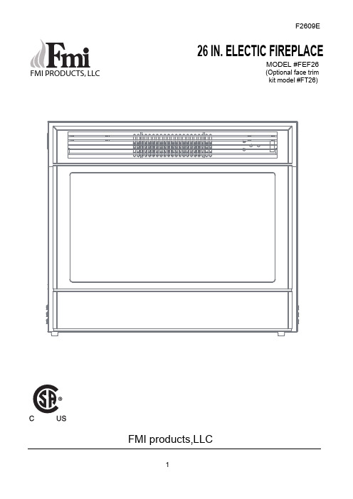
FMI PRODUCTS, LLC26 IN. ELECTIC FIREPLACEMODEL #FEF26(Optional face trimkit model #FT26)F2609E FMI products,LLCTABLE OF CONTENTSSafety Information (3)Operation Instructions (4)Installation Instructons (5)Care and Maintenance (6)Troubleshooting (7)Service Replacement Parts (8)Warranty (9)WARNING: Any use of this appliance other than that recommended by the manufacturer inthis owners manual may cause fire, burns, electric shock and/or other serious injuries or death.When using electrical appliances, basic precautions should always be followed to reduce the risk of fire, electric shock and injury to persons including the following:1. Read the manufacturers instructions completely before using this appliance.2. This appliance will become hot when in use. To avoid burns, do not let bare skin touch hot surfaces. The grillat the top of this heater in particular will become hot when the heater is active. Take special care not to block the air intake or exhaust vents.3. Extreme caution is necessary when the appliance is used by or near children or invalids and whenever the heateris left operating and unattended.4. Do not operate the heater if the power cord or plug has been damaged or the heater has been damaged ormalfunctioned in any way. Take the appliance to an authorized service facility for examination, electrical or mechanical adjustment or repair. 5. Do not use outdoors.6. This heater is not intended for use in bathrooms, laundry areas and similar indoor locations. Never locate heaterwhere it may fall into a bathtub or other water container.7. To disconnect the appliance, turn all controls “OFF”, and then remove the plug from the electrical outlet. 8. The appliance comes equipped with a 3 prong-grounding plug. Do not cut the grounding prong. Connect toproperly grounded 120V outlets only.9. Do not insert or allow foreign objects to enter any ventilation or exhaust openings as this may cause an electricshock or fire, or damage the appliance.10. To prevent a possible fire, do not block air intakes or exhausts in any manner. Do not use on soft surfaces, likea bed, where openings may become blocked.11. All electrical heaters have hot and arching or sparking parts inside. Do not use in areas where gasoline, paint,or flammable liquids are used or stored or where the appliance will be exposed to flammable vapors.12. Avoid using the appliance with an extension cord. Extension cords may overheat and cause a risk of fire. If anextension cord MUST be used, the cord must be No. 16AWG minimum size and rated not less than 1875 Watts. The extension cord must be a 3-prong cord with grounding type plug and cord connection and should not exceed 20’ (6m) in length.13. When transporting or storing the heater, take care to keep both the unit and power cord/plug dry, free fromexcessive vibration and away from heat sources.14. Use the heater only as described in this manual. Any other use not recommended by the manufacturer maycause fire, electric shock, or injury to persons.15. Do not attempt to burn wood or other materials in this heater.Please read and understand this entire manual before attempting to assemble , operate or installthe product.SAFETY INFORMATIONGrate (fold down to reveal control panel)OPERATING INSTRUCTIONS:Read all instructions and warning prior to operating the appliance.Ensure that all controls are in the “OFF” position before plugging the appliance in to a properly grounded electrical outlet.The control panel of the appliance is located behind the wire grate above the window on the front (Fig. 1).Fig. 1Fig. 2Using the Control Panel and the Remote Control:Simulated Flame Effect:o Push button (A) power ON/OFF.o Push button (D) to turn the flame ON/OFF. oPush button (E) to flame brightness. Heat Setting:o Push button (C) once to activate low heat setting o Push button (C) second time to activate high heat setting oPush button (C) third time to activate the “AUTO” function. Turn thermostat (B) dial to desired setting.oPush button (C) fourth time to shut heater offE +-NOTE: Flame and/or heat can work separately or together.PLUGGING IN THE HEATER(Refer to Fig.4):METALCOVER OF GROUNDEDOUTLET BOXThis heater is for use on 120 Volts. The heater has a 3-prong grounded plug (fig. A). If your electrical outlet has only 2 slots (fig. B), you will have to use an adapter (fig. C) to convert from the 3-prong power cord to a 2-slot receptacle. The green grounding plug extending from the adapter must be securely connected to a permanent ground such as a properly grounded outlet box. The adapter should only be used if a proper 3-slot receptacle is not available .NOTE: Adapters are not allowed for use in Canada.A 15 AMP circuit is required to operate this appliance. If the breaker trips when the appliance is running, you may need to move the appliance to another location or unplug other appliances that are on the same circuit.INSTALLATION INSTRUCTIONSFig.46 1/2"26 1/2"21 7/8"(D)WARNING : Before attempting to perform any maintenance on this appliance, turn all controlsto the “OFF” position and unplug. Allow the appliance to be “OFF” for at least 10 minutes before performing any maintenance in order to allow all components to cool properly.CARE AND MAINTENANCEReplacing Light Bulbs:Make sure that all controls are off and that the appliance is unplugged.Wear latex gloves to ensure th at grease/oil from your hands does not transfer to the bulbs. Take hold of each side of the bulb cover panel at the bottom of the firebox and pull straightout (See Fig.5). You can see three 40W light bulbs in the firebox (See Fig.6).Examine the light bulbs to determine which bulbs require replacement.Remove the burnt out bulb and replace with a new 40W bulb –Replace the cover panel (See Fig.7).do not over tighten. To remove dust from glass window, use clean dry cloth.To remove fingerprints or other marks from glass window, use clean damp cloth. Do not spray glass cleaner or other liquids directly onto the window.Clean metal surfaces with a clean damp cloth making sure not to push dust or debris into any air intake or exhaust vents.Do not use abrasive cleaners or spray liquids on any part of the appliance.Periodic cleaning/vacuuming of the fan/heater unit is strongly recommended to ensure that no dirt or foreign objects build up.WARNING: DO NOT EXCEED THE RECOMMENDED BULB WATTAGE.Replace the bulb cover panel.Fig.5Fig.6Fig.7Cleaning:TROUBLESHOOTINGWARNING: Turn off the appliance, unplug and let cool for at least 10 minutes before attemptingto service. Only a qualified professional should attempt to service or repair the appliance.Flame is dim or not present 1. Dimmer control button is set toolow.2. Light bulbs are burned out.3. “Flame wand” has come loosefrom bracket.4. “Flame wand” motor is notfunctioning.1. Push button E“+” to increase light.2. Inspect light bulbs and replace ifnecessary. (see Maintenancesection of this manual)3. Remove back panel. Secureend of “flame wand” back into thesupport bracket.4. Call FMI Technical Service at1-866-328-4537.The appliance turns off and will not turn back on 1. The overheat protection device inthe appliance has been triggered.2. House circuit breaker has beentripped.1. Turn all controls off, unplug theappliance, allow to cool for atleast 10 minutes, then plug backin and restart.2. Reset house circuit breaker.The appliance does not turn on when the button is pushed to “ON” 1. The overheat protection device inthe appliance has been triggered.1. Turn all controls off, unplug theappliance, allow to cool for atleast 10 minutes, then plug backin and restart.Remote control does notwork2. Low batteries.3. Manual controls on the appliancemust be ON” before operatingthe remote control.1. Replace all batteries in theremote control.2. Push the appliance “ON” usingthe manual control panel, thenuse remote control to operate.If using the remote control tooperate the appliance, you must also turn the appliance “ON”using the remote control.Problem Possible Cause Corrective Action“ILLUSTRATED PARTS BREAKDOWN MODEL #FEF26FMI PRODUCTS, LLC2701 S.Harbor Blvd.Santa Ana, CA 927041-866-328-4537FMI PRODUCTS, LLC2701 S.Harbor Blvd.Santa Ana, CA 92704 1-866-328-4537Keep receipt for warranty verification.FMI PRODUCTS, LLC LIMITED WARRANTIESNew ProductsStandard Warranty: FMI PRODUCTS, LLC warrants this new product and any parts there of to be free from defects in material and workmanship for a period of one (1) years from the date of first purchase from an authorized dealer provided the product has been installed, maintained and operated in accordance with FMI PRODUCTS, LLC 's warn-ings and instructions.For products purchased for commercial, industrial or rental usage, this warranty is limited to 90 days from the date of first purchase.Factory Reconditioned ProductsLimited Warranty: FMI PRODUCTS, LLC warrants factory reconditioned products and any parts thereof to be free from defects in material and workmanship for 30 days from the date of first purchase from an authorized dealer pro-vided the product has been installed, maintained and operated in accordance with FMI PRODUCTS, LLC 's warnings and instructions.Terms Common to All WarrantiesThe following terms apply to all of the above warranties:Always specify model number and serial number when contacting the manufacturer. To make a claim under this war-ranty the bill of sale or other proof of purchase must be presented.This warranty is extended only to the original retail purchaser when purchased from an authorized dealer, and only when installed by a qualified installer in accordance with all local codes and instructions furnished with this product. This warranty covers the cost of part(s) required to restore this product to proper operating condition and an allowance for labor when provided by a FMI PRODUCTS, LLC Authorized Service Center or a provider approved by FMI PRODUCTS, LLC . Warranty parts must be obtained through authorized dealers of this product and/or FMI PRODUCTS, LLC who will provide original factory replacement parts. Failure to use original factory replacement parts voids this warranty. Travel, handling, transportation, diagnostic, material, labor and incidental costs associated with warranty repairs, unless expressly covered by this warranty, are not reimbursable under this warranty and are the responsibility of the owner. Excluded from this warranty are products or parts that fail or become damaged due to misuse, accidents, improper installation, lack of proper maintenance, tampering, or alteration(s).This is FMI PRODUCTS, LLC 's exclusive warranty, and to the full extent allowed by law; this express warranty excludes any and all other warranties, express or implied, written or verbal and limits the duration of any and all implied war-ranties, including warranties of merchantability and fitness for a particular purpose to one (1) years on new products and 30 days on factory reconditioned products from the date of first purchase. FMI PRODUCTS, LLC makes no other warranties regarding this product.FMI PRODUCTS, LLC 's liability is limited to the purchase price of the product, and FMI PRODUCTS, LLC shall not be liable for any other damages whatsoever under any circumstances including indirect, incidental, or consequential damages.Some states do not allow limitations on how long an implied warranty lasts or the exclusion or limitation of incidental or consequential damages, so the above limitation or exclusion may not apply to you.This warranty gives you specific legal rights, and you may also have other rights which vary from state to state. For information about this warranty contact:125342-01Rev. A 05/10。
H-26H 压力开关产品说明书

diaphragm
and O-ring
-T
30 PTFE
diaphragm
and O-ring
-SS
120 SS diaphragm
(psi units to
60 psid only)
ACCESSORY
MODEL NO. PRICE DESCRIPTION
EE-2584
$230 Reference Book: Process Plant Instrumentation
+HDWHUV
Band Heaters, Cartridge Heaters, Circulation Heaters, Comfort Heaters, Controllers, Meters and Switching Devices, Flexible Heaters, General Test and Measurement Instruments, Heater Hook-up Wire, Heating Cable Systems, Immersion Heaters, Process Air and Duct, Heaters, Radiant Heaters, Strip Heaters, Tubular Heaters
5 to 54 500 psi 2000 psi 10 A SPDT
PSW-357 465 30 to 200 psid 18 to 180 1000 psi 4000 psi 10 A SPDT
PSW-358 465 60 to 400 psid 45 to 360 1000 psi 8000 psi Dual Setpoint, Fixed Deadband, Buna-N Diaphragm, O-Ring, 1⁄4 NPTF PSW-361 $450 5 to 30 inH2O 0.7 to 1.4 5.4 psi 21.6 psi PSW-362 450 9 to 60 inH2O 0.7 to 2.0 5.4 psi 21.6 psi PSW-363 450 15 to 100 inH2O 1.4 to 2.8 5.4 psi 21.6 psi PSW-364 450 23 to 150 inH2O 2.4 to 4.2 5.4 psi 21.6 psi PSW-365 489 5 to 30 psid 1.0 to 2.1 500 psi 2000 psi
22mm-26mm 电子配件说明书

Exhibit 8.1
Jurisdiction of Incorporation
Cayman Islands Cayman Islands Hong Kong United States Hong Kong Hong Kong Hong Kong United States United States United States United States Malaysia United States Hong Kong Malaysia China China China China China China China China China China China China China China China China China China
List of Subsidiaries as of March 15, 2017*
Company Name
Xinyuan Real Estate, Ltd. Xinyuan International Property Investment Co., Ltd. Xinyuan International (HK) Property Investment Co., Limited XIN Development Group International Inc. South Glory International Ltd. Victory Good Development Ltd. Elite Quest Holdings Ltd. XIN Irvine, LLC Vista Sierra, LLC XIN Development Management East, LLC XIN NY Holding, LLC XIN Eco Marine Group Properties Sdn Bhd 421 Kent Development, LLC Xinyuan Sailing Co., Ltd. AWAN Plasma Sdn. Bhd. Zhengzhou Yasheng Construction Material Co., Ltd. Zhengzhou Jiasheng Real Estate Co., Ltd Zhengzhou Yusheng Landscape Design Co., Ltd. Xinyuan (China) Real Estate, Ltd. Beijing Yue-Mart Commerce and Trade Co., Ltd. Henan Xinyuan Real Estate Co., Ltd. Xi'an Xinyuan Metropolitan Business Management Co., Ltd. Tianjin Xinyuan Real Estate Co., Ltd. Changsha Xinyuan Wanzhuo Real Estate Co., Ltd. Beijing Xinleju Technology Development Co., Ltd. Henan Yue-Mart Commerce and Trade Co., Ltd. Qingdao Xinyuan Xiangrui Real Estate Co., Ltd. Shandong Xinyuan Real Estate Co., Ltd. Zhengzhou Hengsheng Real Estate Co., Ltd. Zhengzhou Mingyuan Landscape Engineering Co., Ltd. Zhengzhou Xinyuan Computer Network Engineering Co., Ltd. Henan Xinyuan Wanzhuo Real Estate Co., Ltd. Suzhou Xinyuan Real Estate Development Co., Ltd.
艾默生CMF系列传感器样本
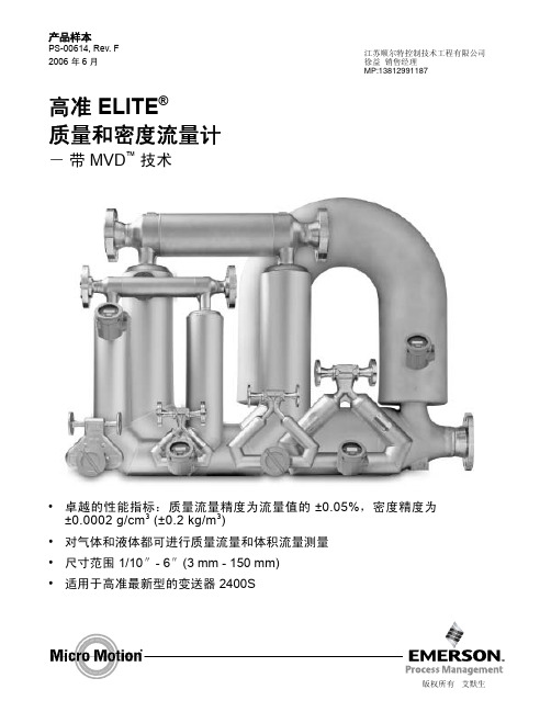
质量和体积流量精度 (2) (3)
2400S 型变送器或增强 ±0.05% 流量(4)(5) 型核心处理器
带 MVD 技术的变送器 ±0.10% 流量(6)
其它所有变送器
±0.10% ± [(零点稳定性/流量值) × 100]% 流量
质量和体积流量重复性
2400S 型变送器或增强 ±0.025% 流量(4)(5) 型核心处理器
产品选择器程序
高准提供在线选型程序用于选择适合您应用的最佳 产品。产品选择器程序允许您指定重要的参数,如 精度,流量范围,压降,量程比等。如需使用产品 选择器程序请访问网址 。
目录
液体流量性能指标 . . . . . . . . . . . . . . . . . . . . . . . . . . . . . . . . . . . 3 气体流量性能指标 . . . . . . . . . . . . . . . . . . . . . . . . . . . . . . . . . . . 5 密度性能指标 (仅液体) . . . . . . . . . . . . . . . . . . . . . . . . . . . . . . . . 8 能量消耗 . . . . . . . . . . . . . . . . . . . . . . . . . . . . . . . . . . . . . . . 8 振动限制 . . . . . . . . . . . . . . . . . . . . . . . . . . . . . . . . . . . . . . . 8 温度性能指标 . . . . . . . . . . . . . . . . . . . . . . . . . . . . . . . . . . . . . 9 压力等级 . . . . . . . . . . . . . . . . . . . . . . . . . . . . . . . . . . . . . . . 11 环境影响 . . . . . . . . . . . . . . . . . . . . . . . . . . . . . . . . . . . . . . . 12 危险区域分类 . . . . . . . . . . . . . . . . . . . . . . . . . . . . . . . . . . . . . 13 结构材料 . . . . . . . . . . . . . . . . . . . . . . . . . . . . . . . . . . . . . . . 21 重量 . . . . . . . . . . . . . . . . . . . . . . . . . . . . . . . . . . . . . . . . . 21 外形尺寸 . . . . . . . . . . . . . . . . . . . . . . . . . . . . . . . . . . . . . . . 22 连接方式选项 . . . . . . . . . . . . . . . . . . . . . . . . . . . . . . . . . . . . . 40 订购信息 . . . . . . . . . . . . . . . . . . . . . . . . . . . . . . . . . . . . . . . 47
CMF商品说明书
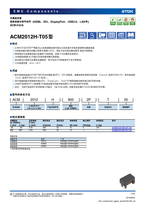
共模滤波器超高速差动信号线用(HDMI 、DVI 、DisplayPort 、USB3.0、LAN 等)ACM-H 系列ACM2012H-T05型特点DVI及HDMI TM等超Gbps 的高速差动信号接口为目的进行开发的宽频带共模滤波器Ω品的差分模式的截止频率方面是6.0GHz ,因此不会对告诉差动信号造成不良影响。
100Ω匹配,控制了不必要的反射成分。
Ω滤波器是为LAN 接口开发的通用模式滤波器。
LAN 传输信号产生不利影响。
: –40 to +85°C用途HDMI TM 的EMI 应对措施:数字TV 、 DVD 刻录机、液晶投影机等信号发送侧 (Source )适用ACM2012H 、信号接收侧(Sink )适用ACM2012E(-T01系列) 。
DVI 、Display port 、Serial ATA 等高速差动信号接口的EMI 的对策。
Ω产品适用于个人电脑等LAN 连接设备中的脉冲变压器ALT4532系列的EMI 对策。
90Ω产品适用于采用高速LAN 接口 (如10G 以太网)的脉冲变压器ALT4532H 系列的EMI 对策。
型号的命名方法特点规格表测量设备*有时使用同等测量设备。
ACM2012H-900-2P-T05系列名称L×W×H 尺寸产品识别符号阻抗线数包装形式管理编号2.0×1.2×1.2 mm(Ω)at 100MHz共模阻抗[at 100MHz]直流电阻[1 line]额定电流额定电压绝缘电阻截止频率特性阻抗型号(Ω)min.(Ω)typ.(Ω)max.(mA)max.(V)max.(M Ω)min.(GHz)typ.(Ω)typ.65900.3030020106100ACM2012H-900-2P-T052803800.503002010——ACM2012H-381-2P-T05测量项目型号厂商共模阻抗4991A Keysight T echnologies 直流电阻4338A Keysight T echnologies 绝缘电阻4339AKeysight T echnologies阻抗频率特性测量设备型号厂商4991A Keysight T echnologies*有时使用同等测量设备。
FORMULA 系列塑壳断路器技术资料201810
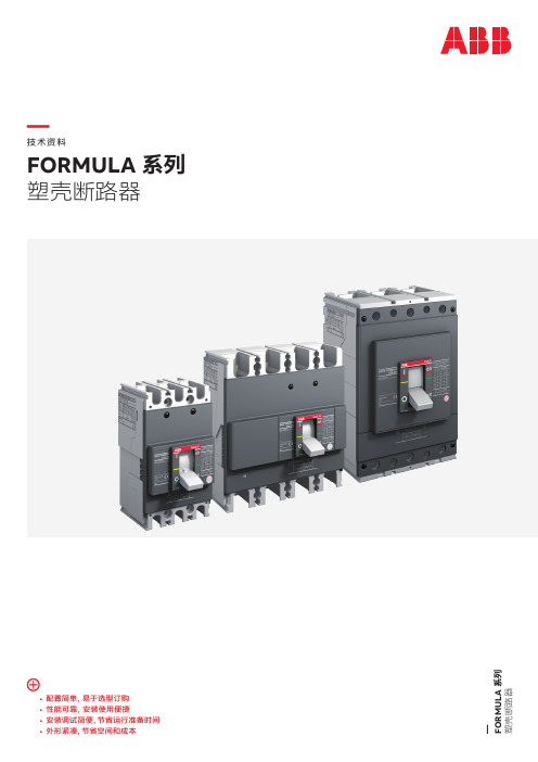
ABB 环境管理体系,社会责任与道德规范标准如下: • 符合 ISO 14001 标准 • OHSAS 18001 工作场所的健康和安全管理体系 • SA8000 管理标准规范商业道德和工作环境
ABB 一直致力于环境保护,体现如下: • 优化选材,加工工艺和包装方式减轻对环境的影响 • 使用可回收利用材料 • 符合 RoHS 指令
10
FORMULA系列 塑壳断路器
— 主要特性 断路器铭牌
正面标签
7
4
1
3
13
9
5
6
7
Made by ABB
10
11 In=100A
1SDC210614F0001
• FORMULA 系列断路器可在环境温度 -25°C 至 +70°C 下正常工作,储存的环境温度为 -40°C 至 +70°C。 所有 FORMULA 断路器的详细温度性能,查阅特性曲线和技术参数。
1SDC210611F0001
1SDC210612F0001
B
• 不同的 IP 防护等级
断路器 带前面盖
—
技术资料
FORMULA 系列 塑壳断路器
• 配置简单,易于选型订购 • 性能可靠,安装使用便捷 • 安装调试简便,节省运行准备时间 • 外形紧凑,节省空间和成本
— FORMULA 系列 塑壳断路器
— 目录
004 – 010 011 – 016 017 – 026 027 – 040 041 – 046 047 – 065 066– 071
迪菲西螺簧型号说明书
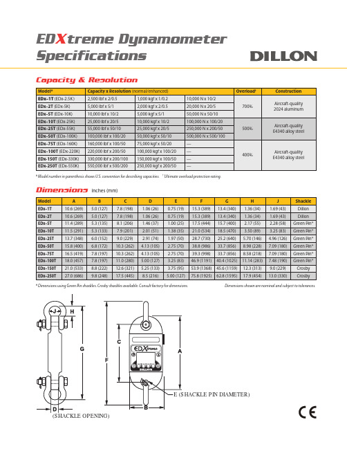
Capacity & Resolution* Model number in parenthesis shows U.S. convention for describing capacities. † Ultimate overload protection rating.Dimensionsinches (mm)* Dimensions using Green Pin shackles. Crosby shackles available. Consult factory for dimensions. Dimensions shown are nominal and subject to tolerances.ED X treme DynamometerSpecificationsDynamometer Specifications Enclosure:Designed to NEMA4X/IP55. Suitable for continuous outdoor use. Accuracy: 0.1% of capacity up to EDX-50T.*0.3% of capacity for EDX-75T and above.*Repeatability: 0.1% of capacity up to EDX-50T.*0.3% of capacity for EDX-75T and above.** Normal resolution mode with Dillon provided shackles.Proof Load: 150% of capacity up to EDX-75T on Load Link.110% of capacity EDX-100T and above on Load Link.Will proof load shackles upon request.Ultimate Overload: See table on reverse.Safe Overload: 200% of capacity.Body Protection:Aluminum and alloy steel capacities are powder coated. Bearings:Unmatched repeatability attained by needle bearings in shackle pin holes up to EDX-5T. Shackle pin acts as inner race. Shackles:Forged industry standard anchor shackles. Models up to EDX5T use precision machined shackle pin. Higher capacities use bar stock pin. Display:128 x 64 dot-graphic LCD display shows up to 6 digits 1.0” (26 mm) high plus annunciators and softkeys. Digits are .11 inches (3 mm) thick for unmatched readability.Display Update Rate: 2 times per second.Peak Capture Rate: 10/100/1,000 HzConnector: Recessed sealed connector may be used for serial communications or connection to a Communicator II remote.RS-232 Communication:Print or extract data easily. Continuous output can drive a scoreboard. Configurable poll character.Calibration:Traceable to the National Institute of Standards and Technology. Certificate included with curve of readings.Battery Life: Stand alone EDXtreme with no radio and no backlight lasts up to 400+ hours. 150 hours continuous with Radio Link System. Use with two C-Cell alkaline batteries. (When using backlight, battery life will be reduced, depending on intensity.)Operating T emperature: -4° F to 158° F (-20° to 70° C).Included with Instrument: All include certificate of calibration, manual and batteries. Plastic carry case included for EDX-1T to EDX-50T.Higher capacities include rugged plywood storage crate. Instru-ments with shackles include centering spacers (EDX-20T & up) and shackle storage crate (EDX-20T to EDX-75T). Display backlight. Options: Shackles. Radio communications.Approval: CE on all capacities excluding 550K. Communicator IISpecificationsEnclosure: Designed to NEMA 3 / IP54 with optional sleeve.Suitable for protected outdoor use.Instrument Size: 9.5 x 5.0 x 2.5 inch (241 x 127 x 64 mm).Accuracy: Not applicable. Only sends and receives digital information. Display: 128 x 64 dot-graphic LCD display can show full readings up to5 instruments.Battery Life: Up to 80 hours continuous radio using (4) AA alkaline batteries.Operating T emperature: -4° F to 158° F (-20° to 70° C). Connectors: Sealed connectors may be used for serial communications and wired connection to an EDXtreme dynamometer.RS-232 Communication: Print or extract data easily. Continuous output can drive a scoreboard. Configurable poll character.Included with Remote: Carry case and batteriesAccessories: Rubberized case protector sleeve.Remote wall mount bracket. Serial and remote cable assemblies. Optional audible alarm: Alarm sounds (105dB) when pre-defined load limit has been exceeded.Approval: CE*Radio SpecificationsFCC Certified: For unlicensed low power devices. No radio licensing or permits required for normal operation.* (In the US and Canada.Check local ordinances in other countries.).Frequency: ISM 2.4 GHz frequency band operates between 2.4 to 2.4835 GHz.Output Level: 10 mW (10 dBm).Display Update Rate: 1 time per second.Number of Links Remote Can Control: Up to 15 addresses. Configuration Address: Automatic and configurable.Antenna: Integral antenna.Range: *Open-air range up to 600 feet, line-of-sight. Indoor range up to 300 feet common dependent on environment. Subject to CEmarking. Low power radio systems are dependent upon interference levels from other radio systems and environmental conditions. Radio devices are not suitable for all applications.Weights。
液晶电视LPL26A电源原理分析
检查高压是否有拉弧包括 高压电容是否有虚焊
检查LH1及连接LH1的相关 器件是否异常
检查变压器各路输出是否 有短路及反馈电路元器件
是否异常
检查TD1是否故障
检查LH1及高压是否短路 等
LPL26A电源板 待机模块(反激式单路稳压)
在接通市电后,待机电路自启动进入工作状态。 提供3.3V直流电压给机芯MCU: 经整流后的直流电压通过RB1/RB2/RB3接到UB1的8脚的内部启动电路,内部对连接5脚的CB4充电,当电压被充到8.7V时 UB1启动,而后绕组N5经DB6整流给5脚供电维持UB1正常工作,次极绕组8脚的输出经DB12整流得到3.3V待机电压;次 级绕组11脚的输出经DB13整流得到15V左右的电压为PWM模块供电。 通过取样电阻RB18/RB19/RB20分压,连接TL431(UB4) 的1脚,光耦UB2的3、4脚接通,对UB1的输出控制,从而输出稳定 的3.3V。同时,变压器TS2的辅助绕组分两路输出:1.一路输出给PFC IC(UF1);2.一路给UB1自身供电。
QW1或QW2故障
UC3模块故障
INVERTER故障 检修
BL_ON=“H” Y
屏是否亮起
无异常
N
现象说明 正常工作 启动故障
过流
LED1状 态
不亮
无故障
故障原因
5
次
灯管开路,VS2大于3.8V,维持 1S秒后关机
1 次 IS1大于3.2V,关机
过压
2 次 VS2大于4.8V关机
电压不平衡(拉弧) 3 次 VS2-VS1大于0.28V,关机
LPL26A电源板 高压INVERTER电路的恒流与保 恒护流的实现:
- 1、下载文档前请自行甄别文档内容的完整性,平台不提供额外的编辑、内容补充、找答案等附加服务。
- 2、"仅部分预览"的文档,不可在线预览部分如存在完整性等问题,可反馈申请退款(可完整预览的文档不适用该条件!)。
- 3、如文档侵犯您的权益,请联系客服反馈,我们会尽快为您处理(人工客服工作时间:9:00-18:30)。
FEATURES:
Specified
by
STAND-OFF VOLTAGE
SOD-123F CASE
APPLICATIONS:
• DIGITAL CAMERAS • CELL PHONES AND ACCESSORIES • DESKTOP AND LAPTOP COMPUTERS • PDA’s
• STAND-OFF VOLTAGE 5 - 170 VOLTS • VERY LOW LEAKAGE CURRENT • LOW CLAMPING VOLTAGE • 200 WATT PEAK POWER DISSIPATION • SMALL, HIGH THERMAL EFFICIENCY, SOD-123F FLAT LEAD PACKAGE
*CMF51A 51 56.7 62.7 *CMF54A 54 60 66.3 *CMF58A 58 64.4 71.2 *CMF60A 60 66.7 73.7 *CMF64A 64 71.1 78.6 *CMF70A 70 77.8 86 *CMF75A 75 83.3 92.1 *CMF78A 78 86.7 95.8 *CMF85A 85 94.4 104 *CMF90A 90 100 111 *CMF100A 100 111 123 *CMF110A 110 122 135 *CMF120A 120 133 147 *CMF130A 130 144 159 *CMF150A 150 167 185 *CMF160A 160 178 197 *CMF170A 170 189 209 * Under development - please consult factory
UNITS W kV °C
MAXIMUM RATINGS: (TA=25°C unless otherwise noted) SYMBOL Peak Pulse Power (10/1000µs Waveform) PPP ESD Voltage (HBM) VESD Operating and Storage Junction Temperature TJ,Tstg ELECTRICAL CHARACTERISTICS: (TJ=25°C unless otherwise noted)
200 ax. Clamp Voltage VC @ IPP (V) 9.2 10.3 11.2 12 12.9 13.6 14.4 15.4 17 18.2 19.9 21.5 23.2 24.4 26 27.6 29.2
PART NO.
Peak Pulse Current IPP A 21.7 19.4 17.9 16.7 15.5 14.7 13.9 13 11.8 11 10.1 9.3 8.6 8.2 7.7 7.2 6.8
Reverse Stand-Off Voltage VRWM (V) 5.0 6.0 6.5 7.0 7.5 8.0 8.5 9.0 10 11 12 13 14 15 16 17 18 Breakdown Voltage VBR @ IT MIN (V) 6.4 6.67 7.22 7.78 8.33 8.89 9.44 10 11.1 12.2 13.3 14.4 15.6 16.7 17.8 18.9 20 MAX (V) 7.0 7.37 7.98 8.6 9.21 9.83 10.4 11.1 12.3 13.5 14.7 15.9 17.2 18.5 19.7 20.9 22.1 Test Current IT (mA) 10 10 10 10 1.0 1.0 1.0 1.0 1.0 1.0 1.0 1.0 1.0 1.0 1.0 1.0 1.0 Reverse Leakage IR @ VRWM (µA) 400 400 250 100 50 25 10 5.0 2.5 2.5 2.5 1.0 1.0 1.0 1.0 1.0 1.0
Marking Code
CMF5.0A CMF6.0A CMF6.5A CMF7.0A CMF7.5A CMF8.0A CMF8.5A CMF9.0A CMF10A CMF11A CMF12A CMF13A CMF14A CMF15A CMF16A CMF17A CMF18A
CM05A CM06A CM065 CM07A CM075 CM08A CM085 CM09A CM10A CM11A CM12A CM13A CM14A CM15A CM16A CM17A CM18A
R0 (14-October 2005)
元器件交易网
Central
Reverse Stand-Off Voltage VRWM (V) 20 22 24 26 28 30 33 36 40 43 45 48
TM
Semiconductor Corp.
CMF5.0A THRU CMF170A UNI-DIRECTIONAL SURFACE MOUNT TRANSIENT VOLTAGE SUPPRESSOR 200 WATTS, 5.0 THRU 170 VOLTS
SOD-123F CASE - MECHANICAL OUTLINE
R0 (14-October 2005)
元器件交易网
CMF5.0A THRU CMF170A UNI-DIRECTIONAL SURFACE MOUNT TRANSIENT VOLTAGE SUPPRESSOR 200 WATTS, 5.0 THRU 170 VOLTS
Central
TM
Semiconductor Corp.
PART NO.
Marking Code
CMF20A CMF22A CMF24A CMF26A CMF28A CMF30A CMF33A CMF36A *CMF40A *CMF43A *CMF45A *CMF48A
CM20A CM22A CM24A CM26A CM28A CM30A CM33A CM36A CM40A CM43A CM45A CM48A CM51A CM54A CM58A CM60A CM64A CM70A CM75A CM78A CM85A CM90A CM100 CM110 CM120 CM130 CM150 CM160 CM170
DESCRIPTION: The CENTRAL SEMICONDUCTOR CMF5.0 Series of Transient Voltage Suppressors are designed to protect sensitive electronic components from high voltage, high-energy transients. High surge capability, low impedance, low clamping voltage, fast response time and small size make this an excellent choice for industrial/consumer applications, such as cell phones, power supplies and portable devices. MARKING CODE: SEE ELECTRICAL CHARACTERISTICS TABLE
ELECTRICAL CHARACTERISTICS: Continued
Breakdown Voltage VBR @ IT MIN (V) 22.2 24.4 26.7 28.9 31.1 33.3 36.7 40 44.4 47.8 50 53.3 MAX (V) 24.5 26.9 29.5 31.9 34.4 36.8 40.6 44.2 49.1 52.8 55.3 58.9 Test Current IT (mA) 1.0 1.0 1.0 1.0 1.0 1.0 1.0 1.0 1.0 1.0 1.0 1.0 1.0 1.0 1.0 1.0 1.0 1.0 1.0 1.0 1.0 1.0 1.0 1.0 1.0 1.0 1.0 1.0 1.0