施密德SHDSL配置命令一览表
SHDSL使用手册
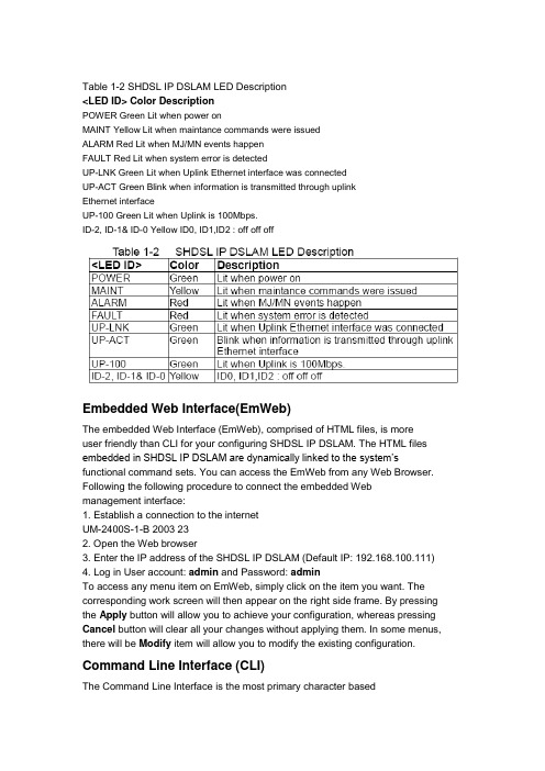
Table 1-2 SHDSL IP DSLAM LED Description<LED ID> Color DescriptionPOWER Green Lit when power onMAINT Yellow Lit when maintance commands were issuedALARM Red Lit when MJ/MN events happenFAULT Red Lit when system error is detectedUP-LNK Green Lit when Uplink Ethernet interface was connectedUP-ACT Green Blink when information is transmitted through uplinkEthernet interfaceUP-100 Green Lit when Uplink is 100Mbps.ID-2, ID-1& ID-0 Yellow ID0, ID1,ID2 : off off offEmbedded Web Interface(EmWeb)The embedded Web Interface (EmWeb), comprised of HTML files, is moreuser friendly than CLI for your configuring SHDSL IP DSLAM. The HTML files embedded in SHDSL IP DSLAM are dynamically linked to the system’s functional command sets. You can access the EmWeb from any Web Browser. Following the following procedure to connect the embedded Web management interface:1. Establish a connection to the internetUM-2400S-1-B 2003 232. Open the Web browser3. Enter the IP address of the SHDSL IP DSLAM (Default IP: 192.168.100.111)4. Log in User account: admin and Password: adminTo access any menu item on EmWeb, simply click on the item you want. The corresponding work screen will then appear on the right side frame. By pressing the Apply button will allow you to achieve your configuration, whereas pressing Cancel button will clear all your changes without applying them. In some menus, there will be Modify item will allow you to modify the existing configuration.Command Line Interface (CLI)The Command Line Interface is the most primary character basedconfiguration interface. Some of configurations not provided in EmWeb can be configured through CLI. You can access CLI from the terminal emulation software.The procedure of connecting to the CLI is as follows:1. Start up the terminal emulation software on the management station.2. If necessary, reconfigure the terminal-emulation software to match the switch console port settings.Bits per second 9600Data bits 8Parity NoneStop bits 1Flow control None5. Log in User account: admin and Password: adminLog In with Embedded Web InterfaceThis section describes how to log into Embedded Web Interface.1. Connect your computer with the uplink port of SHDSL IP DSLAM.2. Open a web browser with the default IP address: http://192.168.100.1113. The log in screen appears as follows:4. Enter your user name. If it is an initial installation, enter admin for user name.5. Enter your password. If it is an initial installation, enter admin for password.Embedded Web Interface MenuThis section describes the overview of the embedded Web interface menu, EmWeb. After your successfully logging into the EmWeb, the screen will appears as follows:Default SettingDisplay the information of default (factory) setting of your SHDSL IPDSLAM.System InformationDisplay the system time, system up time, system up period of yourSHDSL IP DSLAM. It also provides you with the information of software version, hardware version and serial number.Save to FlashAllow you to save your configuration in Flash.Current EventAllow you to view the alarm and event stSTUs of your SHDSL IP DSLAM.Default (Factory) Configuration Settings {Default Setting}This section describes how to get the information of the default setting ofyour SHDSL IP DSLAM.1. Click on “Default Setting” from the SHDSL IP DSLAM Main Menu.The Default Setting screen appears as follows:Displaying your SHDSL IP DSLAM’s System Information {System Information}This section describes how to get the information of your SHDSL IP DSLAM.1. Click on “System Information” from the SHDSL IP DSLAM Main Menu.The System Information screen appears as follows:Save your Configuration to Flash {Save to Flash} This section describes how to save the configuration you have configured toflash. This function will be needed whenever you want to restart your SHDSL IPDSLAM with the updated configuration.1. Click on “Save to Flash” from the SHDSL IP DSLAM Main Menu.The Save to Flash screen appears as follows:2. Submit the Save button.Displaying Current Event { Current Event }This section describes how to view the current alarm and event stSTUs.1. Click on “Current Event” from the SHDSL IP DSLAM Main Menu.The Current Event screen appears as follows:2. Click on next page item in order to view more events. The displayed data will be 20s items per page and it can display totally up to 960s items.3. Click on DELETE ALL button in order to delete all events.Configuring SHDSL IP DSLAMThis section describes how to configure your SHDSL IP DSLAM by selecting System from EmWeb Menu. This section will cover all the function from System Menu. It includes:Configuring Port Filtering {Set Port Filter}Allow you to configure the port filtering function.1. Click on “Set Port Filter” from the System Menu.The Set Port Filter screen appears as follows:2. Click on Enabled button to allow each SHDSL port to communicate back and forth with the uplink Ethernet port only.By selecting Disabled button you allow all SHDSL ports to communicate 34 2003 UM-2400S-1-Bwith each other and also with the uplink Ethernet port.3. Press Apply button in order to submit your configuration.Note: Make sure to save all the configurations in flash by selecting Save to Flash from main menu when you want to restart your SHDSL IP DSLAM.Configuring IP and Location {System IP / Location}Allow you to configure the system IP address and location.1. Click on “System IP / Location” from the System Menu.The System IP / Location screen appears with the default setting and can be configured as follows:2. Configure the IP address you want to set, say 192.168.100.1233. Configure the subnet mask with reference to IP address, say 255.255.255.04. Configure the gateway with reference to IP address, say 192.168.0.15. Configure the system name you want to set, say IP DSLAM6. Configure the site of location you want to set.7. Configure the contact information for servicing SHDSL IP DSLAM.36 2003 UM-2400S-1-B8. Click on the Apply button to submit your changes, or click on the Cancel button if you want to clear all the values you have configured.Configuring Date and Time {System Date and Time}Allow you to configure the date and time of the system.1. Click on “System Date and Time” from the System Menu.The System Date and Time screen appears with the default setting andcan be configured as follows:2. Configure the year you want to set, say 20013. Configure the month you want to set, say 014. Configure the day you want to set, say 015. Configure the hour you want to set, say 206. Configure the minute you want to set, say 017. Configure the second you want to set, say 018. Click on the Apply button to submit your changes, or click on the Cancel button if you want to clear all the values you have configured.38 2003 UM-2400S-1-BChanging your Password {Changing Password}Allow you to change your password.1. Click on “Changing Password” from the System Menu.The Changing Password screen appears with your user name and your password can be changed as follows:2. Enter your old password.3. Enter your new password that you want to change.4. Enter your new password again to confirm.5. Click on the Apply button to submit your changes, or click on the Cancel button if you want to clear all the values you have configured.DSL Line ConfigurationThis section covers how to create, display, modify, or delete the line profile and alarm profile by selecting DSL Line Configuration from EmWeb Menu. This section will cover all the function from DSL Line Configuration Menu.Creating a SHDSL Line Profile {Create Line Profile}This section describes how to create a SHDSL line profile.1. Click on “Create Line Profile” of G.SHDSL from the DSL Profile configuration Menu.The Create Line Profile screen appears as follows:2. Configure the name of line profile, say service 1552K.3. Configure the line profile, for example,Configure the WireInterface, Minimum Line Rate, Maximum Line Rate, PSD, TransmissionMode, RemoteEnabled, PowerFeeding, CurrCondTargetMarginDown, WorstCaseTargetMarginDown, CurrCondTargetMarginUp, WorstCaseTargetMarginUp, UsedTargetMargins, ReferenceClock, and LineProbeEnable as Two Wire, 1552 kbps, 1552 kbps, Symmetric, Region1, Disabled, NoPower, 0s dB, 0s dB, 0s dB, 0s dB, CurrCondDown, LocalClk and Disabled.4. Click on the Apply button to submit your changes, or click on the Cancel button if you want to clear all the values you have configured.Note: Line profile can be created maximum up to 10s profiles.40 2003 UM-2400S-1-BCreating a SHDSL Alarm Profile {Create Alarm Profile}This section describes how to create an SHDSL alarm profile.1. Click on “Create Alarm Profile” of G.SHDSL from the DSL Profile configuration Menu.The Create Alarm Profile screen appears as follows:2. Configure the name of alarm profile.3. Configure the alarm profile. For example,Configure the ThreshLoopAttenuation, ThreshSNRMargin, ThreshES, ThreshSES, ThreshCRCanomalies, and ThreshLOSWS as 0s db, 0s db, 0, 0s ec, 0s ec,4. Click on the Apply button to submit your changes, or click on the Cancel button if you want to clear all the values you have configured.Note: The alarm profile can be created maximum up to 10s profiles.5. Click on Modify button to modify the specified profile.6. Click on Delete button to delete the specified profile.Port ConfigurationThis section covers how to configure a port and subscriber information byselecting Port Configuration from EmWeb Menu. This chapter will cover all the function from Port Configuration Menu.DSL Port Configuration{DSL Port Configuration}Allow you to display, modify and delete the stSTUs of the port. It also provides the configuration of enabling or disabling a port and attaching the specific line profile and alarm profile to a port. The procedures are as follows: 1. Click on “DSL Port Configuration” from the Port configuration Menu.For first time configuration, the DSL Port Configuration screen appears with the default setting as follows:2. Click on the Port No to select the port you want to configure or view.3. The screen will apears as follows:4.Configure the adminstration status as “Up” or “Down”. Here in example , “Up”is configured.5. Attach the line profile, says “DEFAULT”6. Attach the alarm profile, says “DEFAULT”7. Click on the Apply button to submit your changes, or click on the Cancel button if you want to clear all the values you have configured.UM-2400S-1-B 2003 45PVC Configuration{PVC Configuration}Allow you to configure PVC (Permanent Virtual Connection) and VID (VLAN ID) on a port and setting the priority. It also provides the modification and delete function. The procedures are as follows:1. Click on “PVC Configuration” from the Port configuration Menu.For the first time configuration, the PVC Configuration screen appears with the default setting as follows:2. Click on the Port No you want to configure or view.3. Click on the Apply button to sumit your choice.4. Click on Delete button to delete the settings.5. Click on Modify button to configure the specific port, says port1. The screen will apears as follows:6. Configure the VPI, says 87. Configure the VCI, says 818. Configure the administration stSTUs of PVC “Up” or “Down”, says “Up.9. Configure the VID of the port.10. Configure the priority of PVC, says 7. The priority of 0s to 7 is from the lowest to the highest.11. Click on the Apply button to submit your changes, or click on the Cancelbutton if you want to clear all the values you have configured.List of Subscriber {List of Subscriber}Allow you to view the existing information of subscribers and modify them. The procedures are as follows:1. Click on “List of Subscriber” from the Port configuration Menu.For the first time configuration, the List of Subscriber screen appears with the default setting as follows:2. Click on the Port No you want to configure or view.3. Click on the Apply button to sumit your choice.4. Click on Delete button to delete the settings.5. Click on Modify button to configure the specific port, says port1. The screen will apears as follows:6. Configure the subscriber name as you want, says Pantagon.7. Configure the telephone number of subscriber, says 423612588. Write Note for your reference if you need.9. Click on the Apply button to submit your changes, or click on the Cancel button if you want to clear all the values you have configured.Management ConfigurationThis section covers how to configure SNMP access parameters and management IP by selecting Management from EmWeb Menu. This sectionwill cover all the function from Management Menu. It includes:Configuring SNMP Access Parameters and Trap IPs {SNMP}Allow you to configure the SNMP access parameters and trap IPs. The procedures are as follows:1. Click on “SNMP” from the Management Menu.For the first time configuration, the SNMP screen appears with the defaultsetting of the community string” public” as follows:2. Configure the VID (VLAN ID) of the system3. Configure the trap IP Addresss as you want. The trap IP can be created maximum up to 5.4. Click on the Apply button to submit your changes, or click on the Cancel button if you want to clear all the values you have configured.Configuring Management IP {Management IP}Allow you to configure the management IPs so that only with thoseconfigured management IPs can access to your SHDSL IP DSLAM remotely.The procedures are as follows:1. Click on “Management IP” from the Management Menu.The Management IP screen appears as follows:2. Configure the management group as you want. The management IP group can be created maximum up to 5 groups.3. Click on the Update button to submit your changes, or click on the Cancel button if you want to clear all the values you have configured.SHDSL MaintenanceAllow you to configure the maintenance operations on SHDSL units. The procedures are as follows:1. Click on “SHDSL Maintenance” from the Main Menu.The SHDSL Maintenance screen appears as follows:4. if you want to config the setting of a specified port, click on the Modify of the Action field, and an embadded hyperlink will help you modify the por t’ssetting. The screen apprears as follows.5. Click on the Apply button to sumit your configuration. Performance MonitorThis section covers performance monitor by selecting DSL Port Performance from EmWeb Menu. It includes:Show SHDSL Span Status { Span Status }Allow you to view the configuration information of the SHDSL span on SHDSL IP DSLAM.1. Click on “Span Status” of G.SHDSL from the DSL Port Performance Menu. The Span Status screen appears as follows:Show Span Status:Show Inventory { Inventory }Allow you to view to view the inventory information of a SHDSL span.1. Click on “Inventory” of G.SHDSL from the DSL Port Performance Menu. The Inventory screen appears as follows:Show Endpointcurr{ Endpointcurr }Allow you to view current stSTUs and performance information for segment endpoints in SHDSL line.1. Click on “Endpointcurr” of G.SHDSL from the DSL Port Performance Menu.The Endpointcurr screen appears as follows:SHDSL Previous 15-MIN Performance Management {Pre-15min PM}Allow you to view the SHDSL information of Previous 15-MIN Performance Management.1. Click on “Pre-15min PM” of G.SHDSL from the DSL Port Performance Menu. The Pre-15min PM screen appears as follows:SHDSL Previous 1 Day Performance Management {Pre-1DayPM}Allow you to view the SHDSL information of Previous 1 Day Performance Management.1. Click on “Pre-1Day PM” of G.SHDSL from the DSL Port Performance Menu. The Pre-1Day PM screen appears as follows:。
H3C命令大全
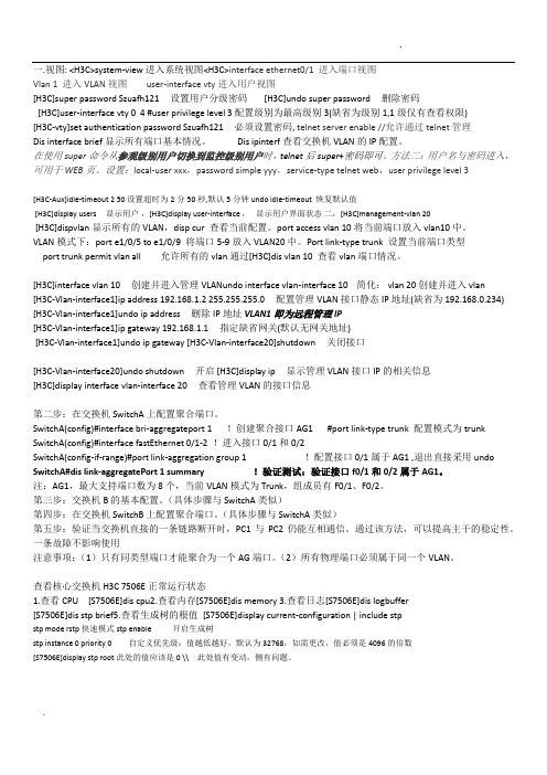
一.视图: <H3C>system-view 进入系统视图<H3C>interface ethernet0/1 进入端口视图Vlan 1 进入VLAN视图user-interface vty进入用户视图[H3C]super password Szuafh121 设置用户分级密码 [H3C]undo super password 删除密码[H3C]user-interface vty 0 4 #user privilege level 3配置级别为最高级别3(缺省为级别1,1级仅有查看权限)[H3C-vty]set authentication password Szuafh121 必须设置密码, telnet server enable //允许通过telnet管理Dis interface brief显示所有端口基本情况。
Dis ipinterf查看交换机VLAN的IP配置。
在使用super命令从参观级别用户切换到监控级别用户时,telnet后super+密码即可。
方法二:用户名与密码进入,可用于WEB页。
设置:local-user xxx,password simple yyy,service-type telnet web,user privilege level 3[H3C-Aux]idle-timeout 2 50 设置超时为2分50秒,默认5分钟 undo idle-timeout 恢复默认值[H3C]display users 显示用户,[H3C]display user-interface ,显示用户界面状态二,[H3C]management-vlan 20[H3C]dispvlan显示所有的VLAN,disp cur 查看当前配置。
port access vlan 10将当前端口放入vlan10中。
VLAN模式下:port e1/0/5 to e1/0/9 将端口5-9放入VLAN20中。
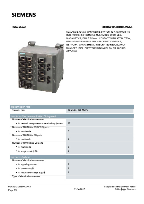
西门子SCALANCE X212-2Managed IE交换机数据手册说明书
● media redundancy protocol (MRP) with
Yes
redundancy manager
● Parallel Redundancy Protocol (PRP)/operation Yes in the PRP-network
● Parallel Redundancy Protocol
No
(PRP)/Redundant Network Access (RNA)
● Passive listening
Yes
Product functions / Security
Protocol / is supported
● SSH
Yes
Product functions / Time Product function
2-pole terminal block 4-pole terminal block
Yes
24 V
0.1 A
DC
24 V 18 V 32 V Yes 1.1 A / 33 V 0.33 A
7.92 W
-40 ... +60 °C -40 ... +70 °C -40 ... +70 °C
95 %
IP30
Cascading in the case of a redundant ring / at
100
reconfiguration time of <\~0.3\~s
Cascading in cases of star topology
any (depending only on signal propagation time)
Product functions / Redundancy
shdsl
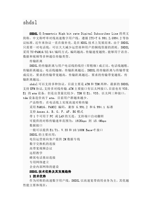
shdslSHDSL是Symmetric High bit rate Digital Subscriber Line的英文简称,中文称呼单对线高速数字用户线,遵循ITU-T G.991.2,G994.2等协议标准。
近年来协议一直在做补充。
是在HDSL技术上发展而来,由于SHDSL 只需要一对电话线,可以大大减少运营商和用户的铜线资源的消耗。
SHDSL 采用TC-PAM16/32/64/编码方式,编码越高,传输速度越快。
能够用于语音、数据和视频等多种通信传输类型。
传输距离SHDSL的传输距离与用户电话线的线径(即粗细)成正比,电话线越粗,传输距离越远,电话线越细,传输距离越近。
SHDSL的传输距离与传输带宽成反比,要求的传输带宽越高,传输距离越近,要求的传输带宽越低,传输距离越远。
shdsl可以支持多种协议,目前主要是ATM和TDM两种,最新的SHDSL 支持EFM协议,支持多对线传输.ATM主要接口有以太网接口,目前也有V35、E1 的atm设备,但是出货量比较少。
TDM有E1、V35、以太网三种接口,tdm设备造价高于atm,目前用户群越来越少。
产品特性; 在电话线上实现高速对称传输采用PAM16、PAM32 编码,兼容 G.991.2 和G.994.1 标准支持Annex.A、B、G、F、AF、BG模式带1个可用于PC 或LAN的互连,支持端口自动翻转可提供的对称传输速率范围为:192Kbps 到 15.4Mbps数据接口一般可以提供E1/T1、V.35和10/100M Base-T接口SHDSL的主要应用:电信运营商向客户提供2M数据专线数字交换机的连接高带宽视频会议远程教学蜂窝电话基站连接专用网络建立企业内部网络的建设SHDSL技术优势及其发展趋势1 技术优势作为对称的高速数字用户线,SHDSL以高速宽带商用业务为主,其优越性能主要体现在:(1)支持对称双向通信与传统的ADSL技术不同,SHDSL所提供的是双向对称业务。
zxdsl新开局步骤

AturConfMinUpshiftTime [0-16383](Def:0)// 用户端的最小上调时间间隔
AturConfMinDownshiftTime [0-16383](Def:0)// 用户端的最小下调时间间隔
dsl(config)$ slot dsl-mpvc 1 进入新增加单板
dsl(cfg-slot-dsl(m)-1)$ pvid 1026-1073 配置端口PVID 必须和端口VLAN相对应
dsl(cfg-slot-dsl(m)-1)$ atm pvc 0:32 pvc1
dsl(cfg-slot-dsl(m)-1)$ adslnfMaxSnrMgn [0-310](Def:120)// 用户端的最大噪声裕度
AturConfMinSnrMgn [0-310](Def:0)// 用户端的最小噪声裕度
AturConfDownshiftSnrMgn [0-310](Def:0)// 用户端的下调的噪声余度间隙
AturChanConfInteMaxTxRate[32-1536])(Def:1024):4096//用户端的交织信道最大传输速率
AturChanConfMaxInterDelay[0-255](Def:32)// 用户端的最大交织时延
创建单板数据
dsl(config)$ card slot 1 cardtype asikb 添加单板
Login:vdsl
Password:vdsl
ChenJiaoYuan_9210>ena
Password:zxedsl
DOORS使用手册

DOORS 使用手册1.安装运行TelelogicDOORS9_1ClientInstaller.msi程序。
设置服务器端口及地址DataBase Pore:36677DataHost:103.198.2.215在客户端安装时需要设定License服务的制定如下图设定2.登陆上图是DOORS界面,第一次进入DOORS,建议修改密码,Tools-Options-Password,如下图所示,密码至少为6位,点击<Change Password>,输入新的密码即可。
2.1.附:添加DOORS用户(管理员)管理员进入DOORS 后,点击图标,进行用户添加,还可以把该用户加入某个组。
3.导入在DOORS中点击导入文档的目录位置,然后打开需要导入DOORS的Word文档,一在导入时,如果保留章节标号,忽略文档的格式,则不要选中<Remove heading numbers>和<capture paragraph styles>,如图:导入设置。
设置完毕后,点击“Export”。
导入完毕之后,要保存。
图:导入设置4.基本操作4.1.文件夹管理4.1.1.创建folder或project管理员可以创建新的folder和project。
Folder下面可以建project,project下面也可以建folder。
点击需要新建folder的目录,右键New-folder或者File-New-folder来建立新的folder,如图:创建folder和project所示,建立project的方法类似。
图:创建folder和project4.1.2.控制folder的权限点击某个folder,右键Properties-Access,如图6所示,共有5种权限:♦Read(R)-可读,如果没有可读权限,该folder不会显示在你DOORS界面;♦Modify(M)-修改folder的名称和描述;♦Create(C)-在folder中创建新的module,folder和project,并能粘贴已有的module,folder和project到该folder下;♦Delete(D)-删除、取消删除、清除folder,还可以剪切folder到剪贴板。
AN5006-15命令行配置
20Mbps;
Admin\profile(XA32Plus)# upstream max linerate 1024
Admin\profile(XA32Plus)# downstream max linerate
20000
Admin\profile(XA32Plus)#
将该模板应用于端口,即与端口绑定。
Admin\profile# set port 1:1-1:24 attach dsl-profile vf1
Admin\profile#
创建VLAN(单VLAN)
若是给每个端口分配一个VLAN,则按如下方法批处理:创
建整框128用户上网VLAN,PVC为0,VLAN ID为10~
号上联口,经OLT设备,与城域网连接到Radius服务器(IP为
10.6.6.6/16),设置VLAN ID为9;以Tag方式,通过4号上联
口,经OLT设备,与城域网连接到ANM2000网管客户端(IP为
10.8.8.8/16),设置VLAN ID为4000。设置XA32盘端口的下
行交织深度为8,下行速率为2Mbps,上行交织深度为8,上行速
<0-6> svid <vid> basecvid <vid> uplink <portlist>
delete stacking bulk vlan slot <slotlist> port <portlist> pvc
<0-6>
create stacking vlan <name>
set stacking vlan <name> [add|delete] {slot <slotlist> port
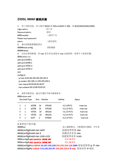
ZXDSL9806E简明开局
ZXDSL9806E简明开局登陆后,察看单板状态(注意如果某槽位用户板没插,会显示一个testing状态,那是正常)DSL# show cardSlot CardType CardState HardVer PortNum PortType------------------------------------------------------------------------1 ATTDB up 1 16 ADSL2 ATTDB up 1 16 ADSL3 SCCE up 1 2 10/100ME初始化重启DSL# eraseDSL# reboot查看MAC地址与其他设备有没有冲突。
DSL# show ip subDest IP Mask VID Status----------------------------------------------------------------------------192.168.2.2 255.255.255.248 4094 activeIn band-------MAC address : 00:D0:D0:11:31:02Out of band-----------IP address : 10.61.86.51Netmask : 255.0.0.0MAC address : 00:D0:D0:11:21:31如果MAC有冲突,需要修改:改过mac要重启生效,不过建议等候面带内数据完成后一次重启。
DSL# enablePassword:zxedslDSL$ deb mo 12345DSL$ deb mo 888999 p1 00:d0:d0:98:06:e0.DSL$ show ip subDest IP Mask VID Status----------------------------------------------------------------------------192.168.2.2 255.255.255.248 4094 activeIn band-------MAC address : 00:D0:D0:98:06:E0Out of band-----------IP address : 10.61.86.51Netmask : 255.0.0.0MAC address : 00:D0:D0:11:21:31假设网管vlan 2000,用户vlan 101-132,每用户一个vlan。
各类操作系统安全基线配置及操作指南

置要求及操作指南
检查模块 支持系统版本号 Windows Windows 2000 以上 Solaris Solaris 8 以上 AIX AIX 5.X以上 HP-UNIX HP-UNIX 11i以上 Linux 内核版本 2.6 以上 Oracle Oracle 8i 以上 SQL Server Microsoft SQL Server 2000以上 MySQL MySQL 5.x以上 IIS IIS 5.x以上 Apache Apache 2.x 以上 Tomcat Tomcat 5.x 以上 WebLogic WebLogic 8.X以上
Windows 操作系统 安全配置要求及操作指南
I
目录
目
录 ..................................................................... I
前
言 .................................................................... II
4 安全配置要求 ............................................................... 2
4.1 账号 ..................................................................... 2
4.2 口令 编号: 1 要求内容 密码长度要求:最少 8 位 密码复杂度要求:至少包含以下四种类别的字符中的三种: z 英语大写字母 A, B, C, , Z z 英语小写字母 a, b, c, , z z 阿拉伯数字 0, 1, 2, , 9 z 非字母数字字符,如标点符号, @, #, $, %, &, *等
USG 2000 G.SHDSL链路接入配置手册
G.SHDSL链路接入G.SHDSL是一种高速对称的传输技术,利用了普通电话线中未使用的高频频段,通过不同的调制方法,在双绞铜线上实现高速数据传输。
其速率可达到5.636 Mbit/s。
如果您所在区域部署了G.SHDSL链路,请阅读此节。
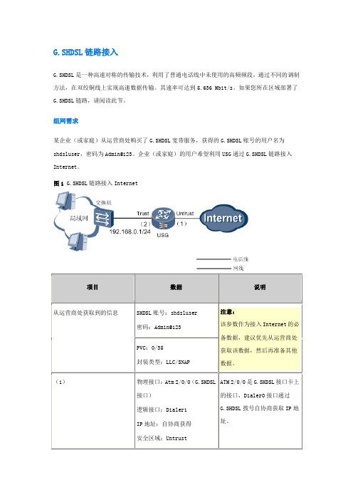
组网需求某企业(或家庭)从运营商处购买了G.SHDSL宽带服务,获得的G.SHDSL账号的用户名为shdsluser,密码为Admin@123。
企业(或家庭)的用户希望利用USG通过G.SHDSL链路接入Internet。
图1 G.SHDSL链路接入Internet配置思路1.如图1所示,用电话线连接USG上的G.SHDSL接口和运营商的电话接口(如果需要同时使用电话,中间可接G.SHDSL分离器)。
用网线连接USG上的二层以太网接口(LAN0-LAN7)和交换机(交换机连接企业或家庭的所有电脑)。
2.接入Internet首先要获取IP地址,因此为了使USG能够从运营商处协商获取IP地址和DNS服务器IP地址,需要配置Dialer接口、G.SHDSL接口(配置界面上显示为Atm接口)和PPPoE会话。
3.为了能够组建企业内部局域网,局域网内的电脑需要从USG获取IP地址和DNS服务器的IP地址,因此需要将USG的二层以太网接口加入VLAN,并在Vlanif上配置IP地址和DHCP功能。
4.为了局域网用户和Internet间的流量通过,需要将Vlanif和Dialer接口加入相应的安全区域,并配置域间包过滤规则。
5.为了确保局域网用户访问Internet时路由可达,需要配置下一跳为Dialer接口的缺省路由。
6.为了实现多个局域网用户能够同时访问Internet,需要配置基于接口的NAT。
操作步骤1.配置Dialer接口,使Dialer接口能够从运营商处协商获取IP地址和DNS服务器IP地址。
# 配置拨号访问组对应的拨号规则,允许所有IP报文进行拨号。
<USG> system-view[USG] dialer-rule 1 ip permit# 创建Dialer1接口,并进入Dialer视图。
ensp基本配置命令及解释
ensp基本配置命令及解释1. 熟悉华为< Huawei > 用户视图< Huawei >system-viem[ Huawei ]系统视图[Huawei]interface Ethernet 0/0/1 进入接口[Huawei-thernet 0/0/1] 接口视图quit 返回上一视图ctrl+z 直接返回用户视图帮助获取帮助息TAB补全命令简写切换语言模式(支持中英文两种语言模式Chinese/English)< Huawei> language-mode ChineseChange language mode, confirm? [Y/N] y< Huawei > display version 查看VRP系统版本< Huawei > display elabel 查看设备型号[Huawei]sysname switch 修改主机名[Switch]配置明文console 口令:[switch]user-interface console 0 进入console 0 唯一端口[switch-ui-console0]authentication-mode password 启用密码[switch-ui-console0]set authentication password simple 123 设置密码为123quit 退出系统视图quit 退出用户视图< switch >display current-configuration 查看配置息配置密文console 口令:[switch]user-interface console 0 进入console 0 唯一端口[switch-ui-console0]authentication-mode password 启用密码[switch-ui-console0]set authentication password cipher 123 设置密码为123Simple 明文Cipher 密文取消密码:[Switch-ui-console0]undo set authentication password配置交换机IP地址[Switch]interface Vlanif 1 接口1[Switch-Vlanif1]IP address 192.16.1.100 24[Switch-Vlanif1]undo shutdown 启动IP地址(华为交换机默认开启,不需要再次开启)配置自动退出超时时间:[Huawei]user-interface console 0 进入console唯一端口[Huaw:ei-ui-console0]idle-timeout 1440设置分钟防止弹出息干扰命令:< Huawei >undo terminal moni 设置用户视图[Huawei]undo info-center enable 设置系统视图保存配置息:< switch >se重启:< switch >reboot恢复出厂设置:< s1 >reset sed-configuration输入y确认恢复出厂< s1>rebootN 不保存Y 确认重启禁用接口与启用接口:[Huawei]interface GigabitEthernet 0/0/2 进入端口号[Huawei-GigabitEthernet0/0/2]shutdown 禁用0/0/2端口[Huawei-GigabitEthernet0/0/2]undo shutdown启用0/0/2端口什么是路由?路由器指的是负责在不同网络之间转发数据的设备,当到达目标的路径很复杂时,由路由器决定最佳路径,路由器也为直连网络的主机充当“网关”角色。
FTOS 配置手册-v1

FTOS 配置手册– V12010-11目录一、基本设置方式 (3)FTOS CLI (4)命令状态 (4)配置远程访问 (5)对 C-Series 和E-Series 的管理接口配置,远程访问 (5)对S-Series 的远程访问配置 (5)配置特权命令状态 password (6)配置物理端口: (6)虚拟局域网(VLAN)路由 (6)虚拟局域网(VLAN) (6)创建一个新 VLAN (7)缺省Vlan --- Default Vlan (7)TRUNK协议 (7)创建静态TRUNK (LAGs) (8)创建动态TRUNK (LACP __ Link Aggregation Control Protocol) (8)将一个trunk加入到一个 VLAN中 (9)配置 PoE (9)配置 STP, MSTP, PVST+ 及RSTP (9)配置 PoE (10)配置交换机上的系统时间 (11)路由协议设置 (11)一、RIP协议 (11)二、OSPFv2协议 (13)三、静态路由协议 (15)配置静态路由 (15)售后服务 (16)开case的信息准备 (16)常用维护命令 (17)一、基本设置方式一般来说,可以用4种方式来设置路由器:1.Console口接终端或运行终端仿真软件的微机;2.通过Ethernet上的TFTP/FTP服务器;3.通过Ethernet上的TELNET/SSH程序;4.通过Ethernet上的SNMP网管工作站。
如果是第一次登录F10设备,必须通过超级终端以第一种方式进行,此时终端的设置如下: 波特率:9600数据位:8停止位:1奇偶校验: 无当超级终端与F10网络设备通过Console电缆连接好后,可以给F10网络设备加电。
关于Force10交换机C/E系列交换机-Console的线序:关于Force10交换机S系列交换机-Console的线序:S系列交换机 console 口线序:Pin 1 = NCPin 2 = NCPin 3 = RXDPin 4 = GNDPin 5 = GNDPin 6 = TXDPin 7 = NCPin 8 = NC用直连网线和随机带的RJ-45/DB-9 转换头连接S系列交换机 console 口和计算机的串行口。
fds命令
1.运行FDS在dos下,进入输入文件job_name所在的目录,然后键入以下命令即可:fds4 < job_name.data2. FDS命令行格式1.以“&”开头,以“/ ”结尾。
2.每一行都由一个命令标识字符串后跟一些参数构成如:&PDIM XBAR0=-.30, XBAR=0.30, YBAR0=-.30, YBAR=0.30 , ZBAR=1.2 /一:描述初始条件1.HEAD定义输入输出文件名格式:&HEAD CHID=’sample’, TITLE=’A Sample Input File’ /1)CHID 定义了所有和输入文件相关的输出文件的名字,其值不多于30个字符2)TITLE 对输入文件的进一步描述,其值不多于60个字符2.TIME设定模拟时间格式:&TIME TWFIN=10,DT=0.1 /1)TWFIN(Time When FINished):设置模拟结束的时间,在建模过程中将其设为0,可以快速检验模型的正确性。
2)DT 设置迭代的时间步长,若迭代不收敛可以将其调小。
3.PDIM 设定计算域格式:&PDIM XBAR0=-.30,XBAR=0.30,YBAR0=-.30,YBAR=0.30,ZBAR=1.2 /1)定义了点(XBAR0,YBAR0,ZBAR0)和(XBAR,YBAR,ZBAR)所确定的一个矩形计算域,即通过矩形域的两个相应的对角点来定义计算域。
单位为米。
2)XBAR0,YBAR0,ZBAR0 的默认值为0。
3.MISC定义全局变量格式:&MISC SURF_DEFAULT=’CONCRETE’,REACTION=’METHANE’, TMPA=20,DAT ABASE=’c:\nist\fds\database4\database4.data’ /1)定义一些全局参数2)是fds唯一的可调用数据库文件的命令3)决定程序执行LES还是DNS,默认为LES,若执行DNS应加入参数DNS=.TRUE4)SURF_DEFAULT:指定表面默认材质,默认为’INERT’(惰性表面)5)REACTION:指定燃烧的化学计量模式,默认为’PROPANE’(丙烷)6)TMPA:指定环境温度,默认为207)TMPO:指定计算区域外部的温度,默认为208)NFRAMES:指定Thermocouple 数据, slice 数据, particle 数据,和boundary 数据的输出频率。
Domino 8.5 DAOS 功能介绍与配置指南说明书

§ 适用于任何 Domino 支持的操作系统平台, 如 Windows, AIX, Redhat Linux, Solaris, System i 等
3
DAOS 原理 STORY TITLE
§ 实现机制:(如图 1 ) 将附件加密存放在独立的路径下,从而减少 NSF 尺寸
将会显示 DAOSMgr 调用堆栈信息,请 将输出的日志发给 IBM 技术支持工程师分析
18
常见问题 STORY
§ 5.DAOSTIT文LE件夹下存放的 NLO 数量有没有上限?
答:有,子文件夹编号从 0001 开始,每个子文件夹中最多可以存放 40,000 个附件,第 40,001 个附件会被自动写到新的子文件夹 0002 下,最多可以有 1000 个 DAOS 子文件 夹,这样理论上 DAOS 支持的 NLO 上限为 40,000,000 个
§ 7. 若 NSF 中指针指向不存在 .nlo 文件,删除文档 >load fixup -f -d dbname.nsf
§ 8. 清理连续 60 天未被引用的 .nlo 文件 >tell daosmgr prune 60
17
常见问题
STORY
§
1.
TITLE
哪些数据库应该启用
DAOS
?
答:用户的邮件文件,服务器端的归档邮件, Mail*.box ,包含很多附件的数据库
DAOS.Engine.Catalog = Synchronized DAOS.Engine.Encryption = Enabled
DAOS.Engine.Status = Enabled
§ 4. 重新同步 DAOS Catalog >tell daosmgr resync
Hillstone常用配置命令整理
缺省初始密码:hill stone/hill stone查看命令:show,在配置模式下可以直接使用,但需要打全。
show conf inteth0/0 查看配置文件下的子项,常用的有int erfac e、add ress、polic y、sh ow co nf re cord:查看配置文件生成的时间sho w ve rsion:查看系统版本信息、开机时间showservi ce:查看定义的服务(端口)信息sho w ref erenc e ser vicexxxx:查看服务x xxx被引用的情况showadmin auth-serv er:查看管理员登录验证服务器show aaa-serve r rad ius:查看radi us服务器的配置s how s nat/d nat:查看NAT条目sho w ipospfnei/d ataba se/ro ute:查看OSPF的邻接、数据库及路由信息等u nsetall:清除所有配置,恢复出厂设置sa ve(al l):保存配置re boot:重启系统管理类:进入配置模式:co nf ,与cisco类似,但不需要带te rmina lntp serv er 192.168.0.xx x sou rce e th0/0 pref er:定义NTP服务器,指定源端口为et h0/0ntp e nable:打开NT P时间同步cloc k zon e chi na:将时区直接设置为中国c onsol e tim eout10:串口管理超时设置为10分钟ssh time out 10:ssh远程登录起时设置为10分钟loggi ng tr affic on:在全局范围内打安全策略、NAT的log记录。
Dynamas

數位監控系統快速使用手冊程式版本: Version 2.8.3文件版本: Version 1.0.7文件日期: Feb 23, 2010目錄主題1、如何安裝監控卡 (1)主題2、如何安裝DVR監控程式 (3)主題3、如何登入DVR觀看即時影像和啟動錄影 (7)主題4、如何調閲與複製歷史影像 (11)主題5、如何管理帳號密碼 (15)主題6、如何設定RMC觀看遠端DVR的即時影像 (16)主題7、如何設定RMC本機端錄影功能 (19)主題8、如何用RMC調閱本機歷史影像 (21)主題9、如何用RMC調閱遠端DVR的歷史影像 (23)主題1、如何安裝監控卡認識監控卡1、4 Port 監控卡:2、8 / 16 Port 監控卡:安裝監控卡步驟1、先關掉電腦的電源,並將電腦上的電源線拔除。
2、拆除電腦外殼,並且讓自己保持接地。
3、從機殼上移除擴充槽擋板。
4、從防靜電袋中將監控卡取出,將卡插入PCI擴充插槽中(請務必確實插牢)。
5、鎖上監控卡固定螺絲,以確保卡片固定在機殼上。
6、重新裝上機器的外殼,並將攝影機的BNC 訊號線接上監控卡。
7、重新開啟系統電源,即完成硬體安裝的工作了!DVR 與攝影機、麥克風配置監控主機有4路、8路、16路等3種機型,影像輸入皆為BNC 影像接頭,以下簡單說明各機型設備與攝影機的安裝關係圖:V3V4A1V2V1V 代表影像來源(攝影機、Video Input ) A 代表聲音來源(麥克風、Audio Input )1、4路監控主機可接V1、V2、V3、V4,四路影像。
與A1一路聲音。
2、8路監控主機可接V1、V2、V3、V4、V5 、V6、V7、V8八路影像。
與V1的音源A1、V2的音 源A2,二路聲音。
3、16路監控主機可接前八路攝影機(紅字組,在螢幕上為1~8號影像,與攝影機1的音源、攝影機2的音源A2,二路聲音。
後八路攝影機(綠字組,在螢幕上為9~16號攝影 機,與攝影機3的音源、攝影機4的音源A4,二路聲音。
浅谈SHDSL在金盾网三级网络的应用
浅谈SHDSL在金盾网三级网络的应用浅谈SHDSL在金盾网三级网络的应用浅谈SHDSL在金盾网三级网络的应用楚雄消防支队摘要:随着金盾网网络信息建设快速发展,步入信息时代的消防工作对文字、语音、图片等多媒体通信的需求日益增长。
然而,目前大部分支队金盾网三级网络一般采用拨号、ISDN、ADSL等方式来实现网络连接,其连接带宽较窄而远远不能满足上述要求。
那么,如果驻地公安局已经实现2兆宽带上网,我们便可以采用HDSL设备连接驻地公安局的宽带网络,借助其现有资源来低成本的建设三级宽带网。
关键词:浅谈SHDSL金盾网应用1.三级网网络常用接入技术对比1.1调制解调器(MODEM),是计算机与电话线之间进行信号转换的装置,由调制器和解调器两部分组成,调制器是把计算机的数字信号(如文件等)调制成可在电话线上传输的声音信号的装置,在接收端,解调器再把声音信号转换成计算机能接收的数字信号。
通过调制解调器和电话线就可以实现计算机之间的数据通信。
即使最新的基于V.90标准的Modem也只区区56Kbps,对于包括视频信号的多媒体传输而言,显然是浅溪行大船。
1.2ISDN(IntegratedServicesDigitalNetwork)综合业务数字网,虽然ISDN的传输线路使用的还是普通的电话线,但在上面传送的却是数字信号。
ISDN包括两种:PRI接口的宽带ISDN(B-ISDN)和BRI接口的窄带ISDN(N-ISDN)。
宽带ISDN提供30B+D信道,带宽可高达2Mbps,一般用于中继接入服务。
普通用户使用的一般是窄带ISDN(俗称“一线通”),它提供两个B信道(64Kbps+64Kbps)和一个D信道(16Kbps),最高上网速率为128Kbps。
1.3xDSL(DigitalSubscriberLine,数字用户线)是以钢轴双绞线为传输煤质的数字用户环路技术的统称,他采用多种调制技术,在现有的PSTN用户法上引入高速传输技术。
第11章 G.SHDSL配置
11.1.2 基本指令描述
命令 描述 配置模式
copyright2014 迈普通信技术股份有限公司,保留所有权利
1
G.SHDSL 配置手册
controller shdsl slot dsl-group number [pairs link]
*进入指定槽位号 slot 的控制器 config 配置模式 *创建一个接口, 指定接口使用 config-controller 的链路 link(线对) ,创建成功 后自动进入 dsl-group 配置模 式。进入一个已经创建的接口 的 dsl-group 配置模式,不需要 输入链路
删除一个或全部 G.SHDSL 接 口 选择使用的标准,缺省是 b *选择工作模式,缺省是 cpe 选择工作速率,缺省是 auto 选择线路编码,缺省是 auto 选择功率回退,设置的 value 是对端的功率回退值,缺省是 auto
config-controller config-controller-dsl-group config-controller-dsl-group config-controller-dsl-group config-controller-dsl-group config-controller-dsl-group
3
G.SHDSL 配置手册
co cpe
局端工作模式 用户端工作模式
【缺省情况】缺省工作在 cpe 模式。 shdsl ,可以选择指定的速率,也可以选择自动协商。两端都是自动协商时,速率 取决于线路的质量,并与线路质量成正比。一端指定速率,一端自动协商,则在协商成功的情况下速率 等于指定的速率。两端都指定速率,且速率不相同,协商会失败,不能建立连接。 shdsl rate { value | auto } 语法 value 描述 单位 Kbps。线路编码采用自动协商模式时,取值范围 192~5696;线 路编码采用 16-TCPAM 模式时,取值范围 192~3848;线路编码采用 32-TCPAM 模式时,取值范围 768~5696 auto 自动协商数据速率。线路编码采用自动协商模式时,协商速率范围 192~5696;线路编码采用 16-TCPAM 模式时,协商速率范围 192~ 3848;线路编码采用 32-TCPAM 模式时,协商速率范围 768~5696 【缺省情况】缺省工作在 auto 模式。 注意: 选择指定的数据速率时,如果已经选择了指定线路编码,且数据速率与线路编码不匹配,则配置线 路速率会失败。 对于多线对接口,指定的数据速率是单线对速率,取值范围变为 2304~5696,接口的实际数据速率 等于该速率与线对个数的乘积。 shdsl coding
开局配置
9806(config)#ip route0.0.0.0 0.0.0.010.107.133.1添加设管理网关和由
9806(config)#ip route172.143.0.0255.255.0.0172.143.247.1添加设语音网关路由
共四个升级文件一此类推:
Sccb.bin
Sccb_fw.bin
Sccb_sv.bin
Bsccb.bin
9806#Reboot重启
F822设备开局
F822-1(config)# interface gei_0/3/1进入F822上联PON口
F822-1(config-if)#switch vlan 100,256-279,1300 ta把宽带的管理vlan,业务vlan和窄带的管理vlan添加进去
9806(config)# add-vlan 1200-1223创建宽带业务VLAN
9806(config)#adsl-profile DEF8M.PRF创建2M模版
9806(config)#adsl-profile DEF8M.PRF修改2M模版
9806(config)#ip subnet10.107.133.138255.255.255.1282405添加设管理ip和vlan
9806(config)#interface gigabit-ethernet 5/1进入上联板5/1
9806(cfg-if-ge-5/1)#no rate-limit broadcast禁止发广播包
9806#save
6.窄带配制:
9806(ag)# get-mgc mgcid 1显示mgcid 1软交换设置
力仕 3086 G.SHDSL 集线器使用说明书
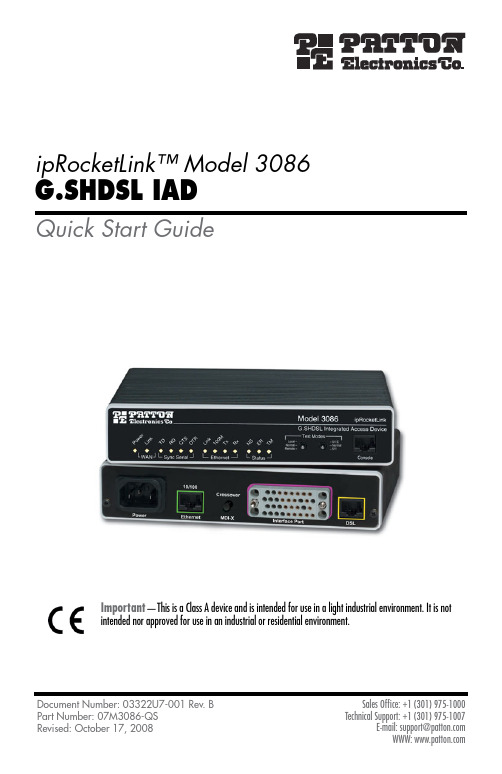
ipRocketLink™ Model 3086G.SHDSL IADQuick Start GuideImportant—This is a Class A device and is intended for use in a light industrial environment. It is notintended nor approved for use in an industrial or residential environment.Document Number: 03322U7-001 Rev. B Sales Office: +1 (301) 975-10001.0 Power up the IADYour IAD comes with one of the following power supply options:•Internal AC power supply with detachable power cord•External AC adaptor with detachable power cord•Internal DC power supply—no power accessories are included1.1 Models with internal AC power supply1.Insert the female end of the AC power cord into the internal power supply connector.2.Connect the male end of the power cord into an AC power outlet (100–240 VAC).1.2 Models with external AC adaptor1.Connect female plug of the AC power cord to the AC adaptor provided.•This device contains no user serviceable parts. The equipment shall bereturned to Patton Electronics for repairs, or repaired by qualifiedservice personnel.•Mains Voltage: Do not open the case the when the power cord isattached. Line voltages are present within the power supply whenthe power cords are connected. The mains outlet that is utilized topower the devise shall be within 10 feet (3 meters) of the device,shall be easily accessible, and protected by a circuit breaker.•For AC powered units, ensure that the power cable used meets allapplicable standards for the country in which it is to be installed, andthat it is connected to a wall outlet which has earth ground.•For units with an external power adapter, the adapter shall be alisted Limited Power Source.•Hazardous network voltages are present in WAN ports regardless ofwhether power to the unit is ON or OFF. To avoid electric shock, usecaution when near WAN ports. When detaching the cables, detach theend away from the device first.•Do not work on the system or connect or disconnect cables during periods of lightning activity.The interconnecting cables shall be acceptable for external use and shall be rated forthe proper application with respect to voltage, current, anticipated temperature, flam-mability, and mechanical serviceability.WARNING CAUTION2.Connect the barrel-type connector of the AC adaptor to the barrel-type power jack on the ipRocketLink.3.Insert the male plug of the AC power cord into an AC power outlet (100–240 VAC).1.3 Models with internal DC power supply1.Strip insulation 1/4-inch from the electrical wires that will connect the DC power source tothe ipRocketLink.2.Connect the ground terminal from the power source to the ground terminal on the ipRocketLink.3.Connect the negative (-) terminal from the power source with to the negative (-) terminal onthe ipRocketLink.4.Connect the positive (+) terminal from the power source with to the positive (+) terminal onthe ipRocketLink.1.4 Power-up indicationThe Power LED blinks as the ipRocketLink is powering up. When the Power LED stops blinking and remains lit, the ipRocketLink is ready for you to configure.2.0 Configure the IP addressThe ipRocketLink is shipped with a factory-configured IP address assigned to the Ethernet LAN port (green out-line). The address is 192.168.200.10/24. In most cases, you must change the address to be on the same subnet as your PC, as described in the procedures below. If you are not sure which IP address to use for your installa-tion, contact your network administrator.2.1 Connect a PC and log ining the included combination RS232/Ethernet cable and DB9-RJ45 adapter, connect a PC’s serial portFigure 1. Connecting ipRocketLink to the PC’s serial port2.Start a HyperTerminal session on the PC using the settings:9600 bps, 8 data bits, 1 stop bit, no parity, no flow control3.Log in to the ipRocketLink using the factory-default login and password:Login: superuserPassword: superuserLogin successful2.2 Modify the IP address1.Display current IP interface settings for the ipRocketLink Ethernet LAN port.→ip list interfaces <enter>IP Interfaces:ID | Name | IP Address | DHCP | Transport---|------|----------------|----------|--------------1 | ip1 | 192.168.200.10 | disabled | <bridge>----------------------------------------------------2.Modify the IP address for the LAN port according to your network requirements.→ip set interface ip1 ipaddress 10.10.10.5 255.255.255.0Note The above IP address (10.10.10.5/24) is only an example. You must choose an IP address on the same subnet as your PC.3.Verify the new address is correct and save it in system boot memory.→ip list interfaces <enter>→system config save <enter>→3.0 Connect to the local IP networkNow you can connect the ipRocketLink to your local IP network and complete the remaining configuration from your PC using a standard web browser.Connect the ipRocketLink’s Ethernet port (green) to the same Ethernet segment as your PC (see figure 2). The front-panel Ethernet Link LED should turn on. If it does not, press the rear-panel MDI-X switch so that the Ethernet Link LED illuminates.You can check the connection with the ping command. For example shown in figure 2, you would ping 10.10.10.5 from a PC on the IP network.Figure 2. Connecting the ipRocketLink to the local IP network (Model 3086/RIC shown)4.0 Log onto the web management interface You will now access the web management graphical user interface (GUI) to configure the ipRocketLink using a standard web browser (such as Internet Explorer or Netscape browser).1.At your PC, open a web browser and enter the IP address you assigned to the ipRocketLink’s Ethernet LANport in step 2 of section 2.2 “Modify the IP address” on page 4.2.Log in to the web management home page using the username superuser and the password superuser .Figure 3. ipRocketLink web management home page5.0 Connect the G.SHDSL Port1.Obtain single-twisted-pair cable with an RJ-11 plug connector at each end.2.Plug one end of the cable into the (yellow) RJ-11socket (labelled DSL) on the ipRocketLink IntegratedAccess Device.3.Plug the other end of the cable into the RJ-11 wall socket that provides your G.SHDSL service.4.When a DSL link is established the front-panel WAN LINK LED will turn on.6.0 Connect the serial portYour ipRocketLink is equipped with one of the following serial WAN ports for connection to an NTU:•V.35 (M/34 or DB-25)—Model 3086/RIC, Model 3086/RICA•X.21 (DB-15)—Model 3086/RID•T1/E1(RJ-48C and dual BNC)—Model 3086/RIKConnect the serial cable to the ipRocketLink serial port as follows:1.Attach the male connector of the serial cable to the female serial connector on the IAD.2.Attach the other end of the cable to the serial connector on local serial NTU.Note The IAD’s V.35 interface is wired as a DCE. No DTE configuration is possible. If you are directly connect-ing the IAD’s V.35 interface to third-party equipment that cannot be configured as a DTE, you must usea tail-circuit cable. You can purchase a tail-circuit cable from a datacom-supply vendor. A tail-circuitcable will cross-over the necessary V.35 signals so that the two DCE interfaces can communicate.Note The IAD’s X.21 interface is wired as a DCE. No DTE configuration is possible. The IAD’s X.21 interface requires a cable with a male DB-15 connector.7.0 Additional InformationRefer to the ipRocketLink 3086 User Guide located on the CD-ROM shipped with your 3086 Integrated Access Device and available online at /manuals for detailed information about:•Installing, configuring, operating, and troubleshooting,•Warranty, trademark, & complianceA.0 Customer and Technical SupportToll-Free VoIP support: call sip:****************** with a VoIP SIP phoneOnline support: E-mail support: ******************—answered within 1 business dayTelephone support:•Standard: +1 (301) 975-1007 (USA), Monday–Friday: 8:00 am to 5:00 pm EST (1300 to2200 UTC/GMT)•Alternate: +41 (0)31 985 25 55 (Switzerland), Monday–Friday: 8:00 am to 5:00 pm CET (0900 to 1800 UTC/GMT)Fax: +1 (253) 663-5693 (USA) or +41 (0)31 985 25 26 (Switzerland)B.0 Compliance InformationB.1 ComplianceEMC:•FCC Part 15, Class A•EN55022, Class A•EN55024Safety:•UL60950-1/CSA C22.2 No. 60950-1•IEC/EN 60950-1•AS/NZS 60950-1PSTN Regulatory:•FCC Part 68•CS-03•AS/ACIF S043B.2 Radio and TV Interference (FCC Part 15)This equipment generates and uses radio frequency energy, and if not installed and used properly—that is, in strict accordance with the manufacturer's instructions—may cause interference to radio and television recep-tion. This equipment has been tested and found to comply with the limits for a Class A computing device in accor-dance with the specifications in Subpart B of Part 15 of FCC rules, which are designed to provide reasonable protection from such interference in a commercial installation. However, there is no guarantee that interference will not occur in a particular installation. If the equipment causes interference to radio or television reception, which can be determined by disconnecting the cables, try to correct the interference by one or more of the fol-lowing measures: moving the computing equipment away from the receiver, re-orienting the receiving antenna, and/or plugging the receiving equipment into a different AC outlet (such that the computing equipment and receiver are on different branches).B.3 CE Declaration of ConformityProduct Description: ipRocketLink 3086We certify that the apparatus identified in this document conforms to the requirements of Council Directive 1999/5/EC on the approximation of the laws of the member states relating to Radio and Telecommunication Terminal Equipment and the mutual recognition of their conformity.The safety advice in the documentation accompanying this product shall be obeyed. The conformity to the above directive is indicated by the CE sign on the device.The signed Declaration of Conformity can be downloaded from /certifications/.B.4 Authorized European RepresentativeD R M GreenEuropean Compliance Services Limited.Avalon House, Marcham RoadAbingdon,Oxon OX14 1UD, UKB.5 FCC Part 68 (ACTA) StatementThis equipment complies with Part 68 of FCC rules and the requirements adopted by ACTA. On the bottom side of this equipment is a label that contains—among other information—a product identifier in the format US: AAAEQ##TXXXX. If requested, this number must be provided to the telephone company.The method used to connect this equipment to the premises wiring and telephone network must comply with the applicable FCC Part 68 rules and requirements adopted by the ACTA.If this equipment causes harm to the telephone network, the telephone company will notify you in advance that temporary discontinuance of service may be required. But if advance notice isn’t practical, the telephone com-pany will notify the customer as soon as possible. Also, you will be advised of your right to file a complaint with the FCC if you believe it is necessary.The telephone company may make changes in its facilities, equipment, operations or procedures that could affect the operation of the equipment. If this happens, the telephone company will provide advance notice in order for you to make necessary modifications to maintain uninterrupted service.If trouble is experienced with this equipment, for repair or warranty information, please contact our company. If the equipment is causing harm to the telephone network, the telephone company may request that you discon-nect the equipment until the problem is resolved.Connection to party line service is subject to state tariffs. Contact the state public utility commission, public ser-vice commission or corporation commission for information.The safety advises in the documentation accompanying the products shall be obeyed. Theconformity to the above directive is indicated by the CE sign on the device.B.6 Industry Canada NoticeThis equipment meets the applicable Industry Canada Terminal Equipment Technical Specifications. This is con-firmed by the registration number. The abbreviation, IC, before the registration number signifies that registra-tion was performed based on a Declaration of Conformity indicating that Industry Canada technical specifications were met. It does not imply that Industry Canada approved the equipment.This Declaration of Conformity means that the equipment meets certain telecommunications network protective, operational and safety requirements. The Department does not guarantee the equipment will operate to the user's satisfaction. Before installing this equipment, users should ensure that it is permissible to be connected to the facilities of the local telecommunications company. The equipment must also be installed using an acceptable method of connection. In some cases, the company's inside wiring associated with a single line individual service may be extended by means of a certified connector assembly (telephone extension cord). The customer should be aware that compliance with the above condition may not prevent degradation of service in some situations. Repairs to some certified equipment should be made by an authorized maintenance facility designated by the supplier. Any repairs or alterations made by the user to this equipment, or equipment malfunctions, may give the telecommunications company cause to request the user to disconnect the equipment. Users should ensure for their own protection that the ground connections of the power utility, telephone lines and internal metallic water pipe system, are connected together. This protection may be particularly important in rural areas.Copyright statementCopyright © 2008, Patton Electronics Company. All rights reserved.The information in this document is subject to change without notice. Patton Electronics assumes noliability for errors that may appear in this document.Trademarks statementThe term ipRocketLink is a trademark of Patton Electronics Company. All other trademarks presented in this doc-ument are the property of their respective owners.Warranty, Trademark, & Compliance InformationFor warranty, trademark and compliance information, refer to the Models 3086 ipRocketLink User Guide located on the CD-ROM that came with your IAD or available online at .In accordance with the requirements of council directive 2002/96/EC on Waste ofElectrical and Electronic Equipment (WEEE), ensure that at end-of-life you separatethis product from other waste and scrap and deliver to the WEEE collection system inyour country for recycling.____________________________________________________________________ ____________________________________________________________________ ____________________________________________________________________ ____________________________________________________________________ ____________________________________________________________________ ____________________________________________________________________ ____________________________________________________________________ ____________________________________________________________________ ____________________________________________________________________ ____________________________________________________________________ ____________________________________________________________________ ____________________________________________________________________ ____________________________________________________________________ ____________________________________________________________________ ________________________________________________________________________________________________________________________________________ ____________________________________________________________________ ____________________________________________________________________ ____________________________________________________________________ ____________________________________________________________________ ____________________________________________________________________ ____________________________________________________________________ ____________________________________________________________________ ____________________________________________________________________ ____________________________________________________________________ ____________________________________________________________________ ____________________________________________________________________ ____________________________________________________________________ ____________________________________________________________________ ____________________________________________________________________。
- 1、下载文档前请自行甄别文档内容的完整性,平台不提供额外的编辑、内容补充、找答案等附加服务。
- 2、"仅部分预览"的文档,不可在线预览部分如存在完整性等问题,可反馈申请退款(可完整预览的文档不适用该条件!)。
- 3、如文档侵犯您的权益,请联系客服反馈,我们会尽快为您处理(人工客服工作时间:9:00-18:30)。
Availble help Categories1、switch - HW switch commands (Marvell mv88e6083)vlan_mode configure the vlan mode【VLAN的配置模式】enable Enable / Disable a specific port【启用/禁用特定的端口】status状态Shows status of a given port【显示给定的端口状态】statistics统计Shows switch statistics【显示开关统计】configure配置Configure port【端口配置】set_pvid Set default vlan id【设置默认的VLAN ID】set_pvid_trunk Set default vlan id of the trunk port【设置默认的VLAN ID的中继端口】vlan_add Add a vlan to the switch【添加一个VLAN的交换机】vtu_show Shows the VLAN Translation Unit (vtu) content【显示VLAN的翻译单位【vtu】含量】vtu_flush Clear all the vlans【清除所有的VLAN】atu_flush Clear the address learning table【清除地址学习表】atu_show Shows the entries of the databases address learning table【显示了数据库中的条目地址学习表】exit Exit sub menu【退出子菜单】2、service - Service commands【服务指令】ssh SSH commands【SSH的命令】exit Exit sub menu3、conf - Read and write Watson configuration data【沃森读写配置数据】factory Factory related commands【制造厂相关命令】print Print Watson configuration【打印沃森配置】set Set Watson configuration path to value【沃森配置路径设置设置的值】set_obscure Set Watson configuration path to an obscured value【沃森配置路径设置到一个模糊的价值】del Delete subtree from Watson configuration【删除子树从沃森配置】ram_set Set Watson dynamic configuration【设置沃森动态配置】ram_print Print Watson dynamic configuration【打印沃森动态配置】reconf Reconfigure the system according to the current Watson configuration【重新配置系统根据当前沃森组态】restore_factory_macs Copy the LAN, WAN, and Bridge MAC addresses from rg_factory to rg_conf【复制局域网,广域网,并从桥的MAC 地址rg_factory到rg_conf】load_config Load rg_conf from a configuration file on the network【从网络上的配置文件加载rg_conf】exit Exit sub menu4、dsl - Commands to communicate with the SHDSL Controller【命令沟通的SHDSL的控制器)diagnostic诊断Shows SHDSL diagnostic information【显示SHDSL的诊断信息】status状态Shows SHDSL status information【显示SHDSL的状态信息】inventory清单Shows SHDSL inventory information【显示SHDSL的库存信息】statistics统计Shows SHDSL statistics information【显示SHDSL的统计信息】vt Establish/release the connection the virtual terminal【建立/释放连接的虚拟终端】restart_link Restart an SHDSL link【重新启动一SHDSL的链接】default默认Set SHDSL default configuration【设置SHDSL的默认配置】startup_trace Enables/disables the SHDSL startup trace【启用/禁用的SHDSL启动跟踪】eoc_trace Enables/disables the SHDSL eoc trace【启用/禁用的SHDSL平机会跟踪】clock_mode Set clock mode on a specific dsl port. Clock mode 2, 3a_csp,3a_refclock and 3b are not working on stu-c devices becausethere is no refclock conneceted to the hardware.Stu-r devicesuses always the received symbol clock.【设置在一个特定的DSL端口的时钟模式。
时钟模式2,3a_csp,3a_refclock和3b没有工作斯图- C的设备,因为有conneceted的hardware.Stu - R设备没有refclock使用总是收到象征时钟。
】eoc_statistics Shows the eoc statistics of the SHDSL interface【显示了SHDSL的平等机会委员会的统计数据接口】exit Exit sub menu5、upnp - UPnP commandsigd IGD commandsstatus Display UPnP statusexit Exit sub menu6、qos - Control and display QoS datautilization Connection utilization information【利用信息连接】exit Exit sub menu7、bridge - API for managing ethernet bridgeconnection Connect separate network interfaces to form one seamless LANconfig Configure bridgeinfo Print bridge informationmac add/delete mac mappingexit Exit sub menu8、config - API for configuring devicespptps Configure PPTP serverexit Exit sub menu9、firewall - Control and display Firewall and NAT datarestart Stop and start Firewall & NAT【停止并重新启动防火墙及NAT】start Start Firewall & NA T【启动防火墙及NAT】stop Stop Firewall & NAT【停止防火墙及NAT】filter Turn Firewall packet inspection on/off【打开包过滤防火墙检查开/关】mac_cache_dump Dump MAC cache data【丢弃MAC缓存数据转储】dump Display Firewall data【显示防火墙数据】variable Display variables of the firewall rules【显示防火墙规则】trace跟踪Trace packet traversal via the Firewall ruleset【通过防火墙规则集跟踪包遍历】fastpath Turns firewall fastpath feature on/off (default is on)【快捷路径打开/关闭【默认是on)】exit Exit sub menu10、connection - API for managing connectionspppoe Configure pppoe interfacel2tp_vpn Configure l2tpc interfacepptp_vpn Configure pptpc interfacevlan Configure vlan interfaceexit Exit sub menu11、inet_connection - API for managing internet connectionspppoe Configure pppoe internet connectionl2tp Configure l2tpc internet connectionpptp Configure pptpc internet connectionether Configure ethernet internet connectionexit Exit sub menu12、misc – show - API for Watson miscellaneous tasksvlan_add Add VLAN interfacetop Profiling over event loop and estreamexit Exit sub menu13、firmware_update - Firmware update commandsstart Remotely upgrade Watsoncancel Kill running remote upgradeexit Exit sub menu14、log - Controls Watson logging behaviorfilter Controls the CLI session logging behaviorprint Print the contents of a given syslog buffer to the console clear Clear the contents of a given syslog bufferexit Exit sub menu15、dev - Device related commandsexit Exit sub menu16、kernel - Kernel related commandsmeminfo Print memory informationtop Print Watson's processes memory usagecpu_load_on Periodically shows cpu usage.cpu_load_off Stop showing cpu usage (triggered by cpu_load_on).cpu_load_avg Shows average cpu usage of last 1, 5 and 15 minutes.exit Exit sub menu17、system - Commands to control Watson executionhttp_intercept_status Display HTTP intercept statusexit_cli Exit from the CLIps Print Watson's tasksetask_list_dump Dump back trace of all etasksrestore_factory_settings Restore factory configurationreboot Reboot the systemver Display version informationprint_config Print compilation configuration. Search for optionif specifieddate Print the current UTC and local timeexit Exit sub menu18、flash - Flash and loader related commandsboot Boot the systemexit Exit sub menu19、net - Network related commandsdns_route Dyncamic Routing according to DNS repliesigmp IGMP Proxy related commandshost Resolve host by nameifconfig Configure network interfaceping Test network connectivityrg_ifconfig List Watson Network Devicesroute Print route tablemain_wan Print the name of the current main wan deviceintercept_state Print interception stateexit Exit sub menu20、cmd - Commands related to the Command moduleexit Exit from the current CLI session。
