CXB4_U2_ADDITIONAL
莫贾UC-8580系列双核ARM Cortex-A7高速训练到地面计算机说明书

UC-8580SeriesArm Cortex-A7dual-core1GHz train-to-ground computers with4Mini PCIe expansion slots for wireless modulesFeatures and Benefits•Complies with all EN50155mandatory test items1•Supports up to3WWAN connections and2SIM card slots per cellularmodule•Supports1WLAN(IEEE802.11a/b/g/n/ac)connection•Single-panel I/O design for reduced installation space and easiermaintenance•Front-side access panel for easy maintenance•Isolated24to110VDC power input with power-ignition function suitable forvehicle applications•EN50155Tx(-40to70°C)operating temperature for harsh environments•5-year warrantyCertificationsIntroductionMoxa’s UC-8580is an innovative computing platform designed specifically for transportation applications.The UC-8580is available with one of two different types of antenna connectors.The SMA model supports all SMA type connectors.The QMA model supports TNC connectors for GPS and QMA connectors for Wi-Fi/cellular modules,and has four slots for installing wireless modules.2Three slots support4G LTE modules,and one slot supports a Wi-Fi module.Each4G LTE module has two SIM card slots,which can be used to enable redundant cellular network communications or geo-fencing SIM card selection by leveraging the built-in Wireless Manager,a Moxa software utility for cellular and Wi-Fi management.The UC-8580uses an open platform based on Debian8with Linux kernel4.1,allowing solution providers to manage software packages via Debian’s APT(Advanced Packaging Tools),or develop software applications with Moxa’s API Library and GNU C Library.The UC-8580’s single-sided I/O design is ideal for vehicle applications,which typically do not have a lot of room for installing communications devices.The UC-8580also has an access panel on the front side,allowing users to install or change wireless modules,SIM cards,or mSATA cards without removing the entire unit from the wall after being mounted.The UC-8580can be used as a communication-centric computing platform for the following applications:•Vehicle-to-ground communication gateway•TCMS T2G(train-to-ground)gateway•Mobile condition monitoring unit•Ethernet Consist Network T2G gateway•Onboard wireless automated fare collection unit1.This product is suitable for rolling stock railway applications,as defined by the EN50155standard.For a more detailed statement,click here:/doc/specs/EN_50155_Compliance.pdf2.Wireless modules are sold separately.Please contact a Moxa sales representative for details.AppearanceSMA ModelQMA ModelSpecificationsComputerCPU Armv7Cortex-A7dual-core1GHz System Memory Pre-installed1GB DDR3LSupported OS Linux Debian8(Linux kernel v4.1)Storage Slot mSATA slots x1,internal mini-PCIe socketStorage Pre-installed8GB eMMCComputer InterfaceEthernet Ports Auto-sensing10/100/1000Mbps ports(M12X-coded)x2 Serial Ports RS-232/422/485ports x2,software-selectable(terminal block) USB3.0USB3.0hosts x1,type-A connectorsDigital Input DIs x3Digital Output DOs x3Expansion Slots mPCIe slots x4Wi-Fi Antenna Connector UC-8580-LX/8580-T-LX/8580-T-CT-LX:RP-SMA x3UC-8580-Q-LX/8580-T-Q-LX/8580-T-CT-Q-LX:QMA x3 Cellular Antenna Connector UC-8580-LX/8580-T-LX/8580-T-CT-LX:SMA x6UC-8580-Q-LX/8580-T-Q-LX/8580-T-CT-Q-LX:QMA x6 Number of SIMs6SIM Format MiniGPS Antenna Connector UC-8580-LX/8580-T-LX/8580-T-CT-LX:SMA x1UC-8580-Q-LX/8580-T-Q-LX/8580-T-CT-Q-LX:TNC x1 Console Port RS-232(TxD,RxD,GND),4-pin header output(115200,n,8,1) Input/Output InterfaceButtons Reset buttonDigital InputsChannel-to-Channel Isolation3K VDCConnector Screw-fastened Euroblock terminalCounter Frequency25HzDry Contact On:short to GNDOff:openI/O Mode DIPoints per COM3x channelSensor Type Wet contact(NPN or PNP)Wet Contact(DI to COM)On:10to30VDCOff:0to3VDCDigital OutputsConnector Screw-fastened Euroblock terminalCurrent Rating200mA per channelI/O Type SinkVoltage0to30VDCLED IndicatorsSystem Power x1System Ready x1Programmable x1Wireless Signal Strength Cellular/Wi-Fi x12LAN2per port(10/100/1000Mbps)Serial2per port(Tx,Rx)Serial SignalsRS-232TxD,RxD,RTS,CTS,DTR,DSR,DCD,GNDRS-422Tx+,Tx-,Rx+,Rx-,GNDRS-485-2w Data+,Data-,GNDRS-485-4w Tx+,Tx-,Rx+,Rx-,GNDGPS InterfaceHeading Accuracy0.3degreesIndustrial Protocols NMEA0183,version4.0(V2.3or V4.1configurable),UBX,RTCM Receiver Types72-channel u-blox M8engineTime Pulse0.25Hz to10MHzVelocity Accuracy0.05msPower ParametersInput Current 1.66A@24VDC,0.36A@110VDCInput Voltage24to110VDCPower Connector M12A-coded4-pin male connectorPower Consumption40W(max.)Physical CharacteristicsHousing MetalIP Rating IP40Dimensions(with ears)270x134x88mm(10.63x5.28x3.46in)Dimensions(without ears)220x134x88mm(8.66x5.28x3.46in)Weight Product only:2,200g(4.85lb)Installation Wall mountingProtection-CT models:PCB conformal coatingEnvironmental LimitsOperating Temperature Standard Models:-25to55°C(-13to131°F)Wide Temp.Models:-40to70°C(-40to158°F)Storage Temperature(package included)-40to85°C(-40to185°F)Ambient Relative Humidity5to95%(non-condensing)Standards and CertificationsEMC EN55032/24EMI CISPR32,FCC Part15B Class AEMS IEC61000-4-2ESD:Contact:6kV;Air:8kVIEC61000-4-3RS:80MHz to1GHz:20V/mIEC61000-4-4EFT:Power:2kV;Signal:2kVIEC61000-4-5Surge:Power:2kV;Signal:2kVIEC61000-4-6CS:10VIEC61000-4-8PFMFRailway EN50121-4EN50155Railway Fire Protection EN45545-2Safety EN60950-1UL60950-1Shock IEC60068-2-27,IEC61373,EN50155:2017 Vibration IEC60068-2-64,IEC61373,EN50155:2017 DeclarationGreen Product RoHS,CRoHS,WEEEWarrantyWarranty Period5yearsDetails See /warrantyPackage ContentsDevice1x UC-8580Series computerCable1x4-pin header to DB9console cable Documentation1x quick installation guide1x warranty cardDimensionsOrdering InformationModel Name CPU Antenna Connector Type Operating Temp.Conformal CoatingUC-8580-LX Armv7Cortex-A7dual-core1GHzSMA-25to55°C–UC-8580-T-LX Armv7Cortex-A7dual-core1GHzSMA-40to70°C–UC-8580-T-CT-LX Armv7Cortex-A7dual-core1GHzSMA-40to70°C✓UC-8580-Q-LX Armv7Cortex-A7dual-core1GHzQMA-25to55°C–UC-8580-T-Q-LX Armv7Cortex-A7dual-core1GHzQMA-40to70°C–UC-8580-T-CT-Q-LX Armv7Cortex-A7dual-core1GHzQMA-40to70°C✓Accessories(sold separately)Wi-Fi Wireless ModulesUC-8580-WLAN33-AC3transmitter3receiver Wi-Fi card module,3SMA connectors with cablesUC-8500-WLAN33-Q-AC3transmitter3receiver Wi-Fi card module,3QMA connectors with cablesCellular Wireless ModulesUC-8500-4GCat6-Q-APAC LTE Cat.6module for North America and Europe,2QMA connectors with cables,-40to60°Coperating temperatureUC-8500-4GCat6-Q-NAMEU LTE Cat.6module for North America and Europe,2QMA connectors with cables,-40to60°Coperating temperatureUC-8580-4GCat6-NAMEU LTE Cat.6module for North America and Europe,2SMA connectors with cables,-40to60°Coperating temperaturePower AdaptersPWR-24250-DT-S1Power adapter,90to264VAC,24VDC,2.5A DC loadPower CordsPWC-C13US-3B-183Power cord with United States(US)plug,1.83mPWC-C13CN-3B-183Power cord with three-prong China(CN)plug,1.83mPWC-C13AU-3B-183Power cord with Australian(AU)plug,1.83mPWC-C13EU-3B-183Power cord with Continental Europe(EU)plug,1.83mPWC-C13JP-3B-183Power cord with Japan(JP)plug,7A/125V,1.83mPWC-C13UK-3B-183Power cord with United Kingdom(UK)plug,1.83m©Moxa Inc.All rights reserved.Updated Nov23,2022.This document and any portion thereof may not be reproduced or used in any manner whatsoever without the express written permission of Moxa Inc.Product specifications subject to change without notice.Visit our website for the most up-to-date product information.。
SmartLock Kit Quick Setup Guide - DX2-DH2C2.pdf_16

SmartLock with DX2-DH2C2Model Number: DX2-DH2C2SmartLock is an electronic door access and control system for all types of data center enclosures. Supported ComponentsDX2-DH2C2 door handle controller supports the following components::Managing Devices PX3PX3TSPXCSRC Legrand PDUXerus Version 3.6.10 and upDoor Handles Southco H3-EM-60-100Southco H3-EM-62-100Southco H3-EM-64-100Southco H3-EM-65-100Southco H3-EM-66-100Southco H3-EM-67-100Southco H3-EM-68-100Emka Agent EEmka 1150-U5xDirak eLine MLR1000Dirak eLine MLR2X00Dirak eLine MLR2000KPRestrictions for DX2-DH2C2•Always connect DX2-DH2C2 directly to the sensor port. If you are cascading with other sensors, the DX2-DH2C2 must be in the first position, directly connected to the sensor port.•Max. of 1 DX2-DH2C2 with up to 2 electronic door handles per Sensor port•Max. cable length PDU to DX2-DH2C2: 5m•Max. cable length DX2-DH2C2 to door handle: 4m•No support for hot-plugging door handles. Door handle must not be plugged or unplugged from DX2-DH2C2 while contacts are powered.Risk of equipment damage.SMARTLOCK QUICK SETUP GUIDEDX2-DH2C2 InstallationSENSOR I/0RJ-45 portsUse a standard category cable to connect to the PX3, PX3TS, PXC, SRC, orLegrand supported managing product port.DOOR HANDLE 1 - DOOR HANDLE 2Electronic door handle portsUse wiring provided with your door handles.Connect the 8-pin connector end to the door handle port.CONTACT CLOSUREContact closure sensor channelsCC sensors and wiring not included.Connect CC sensors according to their instructions.Bracket InstallationYou can install the bracket accompanying DX2-DH2C2 in order to hang or fasten it properly on an object or position. The bracket can be installed either onto the bottom of DX2-DH2C2 or onto one of its sides.Bracket installed onto DX2-DH2C2's bottom:Bracket installed onto the side of DX2-DH2C2:Next StepsOnce the physical connections are complete, login to your supported managing device to use door handle features in the web interface.Web ConfigurationPeripherals•SmartLock menu option is seen on main menu once door handle are connected, and the Card Readers option appears when door handle with integrated card reader is configured.•In the Peripheral Devices page, two door handles, door locks, and doors are added automatically.SmartLock•Click Smart Lock in the Main menu to open the Door Handle options.•The Smart Lock Controller section on top displays the physical connection to the DX2-DH2C2.•Door Handle 1 and Door Handle 2 correspond to the labels on the sensor.Settings•Click Edit settings.•Door Handle Type: Select your door handle's model.▪If your specific Southco H3-EM model is listed, select it. For all other supported Southco H3-EM models, select "Southco H3-EM".•Timeout: Specify how long the door handle lock can remain open after someone opens the door handle via a smart card or via remote control using the software. When the timeout expires, the door handle lock will be automatically closed. Default is 600 seconds (that is, 10 minutes).•Door Sensor Polarity: Choose the correct setting based on the type of contact closure sensors used to monitor the door: ▪Normally closed: The contact is closed (conducting) when the door is closed and open (not conducting) when the door is open. Default.▪Normally open: The contact not conducting when the door is closed and conducting when the door is open.Note: For both normally closed and normally open sensors, the reported state is "open" when the door is open and "closed" when the door is closed.•Relock on Handle Close: This setting controls auto-locking of door handles. Select "Only if door closed" to delay auto-locking of door handles until "Door State" and "Door Lock State" are both verified as "Closed". Select "Always" to relock door handles automatically.•Connected Device: If your door handle has a connected device, such as a keypad, select it from the list.•Save your changes.•Once the Door Handle State and Type is detected, the information populates in the Door state section.•Optional: You can rename each Door Handle component by clicking the item and editing settings.•After these configurations, return to the Peripherals Devices page. This page now displays state, type and Position options for each configured component.Optional Setting: Unlock Front and Rear Doors SimultaneouslyBy default, the configuration is set to unlock only one lock at a time to preserve power. You must change the Active Powered Dry Contact Limit to 2 if you require unlocking the front and rear door simultaneously at the rack.•Click Peripherals in the Main menu.•Click . to expand and click Peripheral Device Setup.•Click Save for the new changes.For SRC, the same settings are available on the SRC page.Note: With some door handles, while you open and close one door handle, the second door handle is powered off briefly to conserve power. Once the first door handle is closed and locked, power resumes to the second handle and it is ready to use.SmartLock KitsSouthco Door Lock Kits EMKA Door Lock KitsSML-KIT-CARD-04: 2 H3EM-66, DX2-DH2C2 SML-KIT-EKA-AGE-1D: 1 EKA-AgentE, DX2-DH2C2SML-KIT-CARD-05: 2 H3EM-66, DX2-DH2C2, Retrofit KIT SML-KIT-EKA-AGE-2D: 2 EKA-AgentE, DX2-DH2C2SML-KIT-SCO-60-2D: 2 H3EM-60, DX2-DH2C2 SML-KIT-EKA-AGE-1DL: 1 EKA-AgentE-L, DX2-DH2C2SML-KIT-SCO-62-2D: 2 H3EM-62, DX2-DH2C2 SML-KIT-EKA-AGE-2DL: 2 EKA-AgentE-L, DX2-DH2C2SML-KIT-SCO-64-1D: 1 H3EM-64, 1 H3EM-60, DX2-DH2C2 SML-DRK-MLR2500SML-KIT-SCO-64-2D: 2 H3EM-64, DX2-DH2C2 SML-DRK-MLR2500KSML-KIT-SCO-65-1D: 1 H3EM-65, 1 H3EM-60, DX2-DH2C2SML-KIT-SCO-65-2D: 2 H3EM-65, DX2-DH2C2SML-KIT-SCO-66-1D: 1 H3EM-66, 1 H3EM-60, DX2-DH2C2。
富士通服务器PRIMERGY CX400 M4多节点服务器说明书
Data SheetFUJITSU PRIMERGY CX400 M4 多節點伺服器專為工作負載設計的模組機架式電源FUJITSU PRIMERGY伺服器能執行任何工作負載與因應瞬息萬變的業務需求。
隨著業務拓展,對於應用的需求也隨之升高。
每項需求均需佔用資源,因此必須尋找能夠優化運算的方式,為使用者提供更佳服務。
PRIMERGY系統具備完整的產品組合,包含適用於遠端分公司的PRIMERGY直立式伺服器、萬用機架式伺服器,以及密度最佳化的多節點伺服器,有助於提升運算能力,配合業務需求。
經得起商業考驗的創新系列產品,以其高效率降低營運的成本與複雜程度,使日常運作更加靈活,並可無縫整合,助您專注在核心業務上。
FUJITSU PRIMERGY CX多節點系統是雲端、超融合式與高效能運算解決方案的理想平台,提供資料中心與分公司大量的運算效能,以執行虛擬化環境、複雜運算、伺服器整併及高可用性情境。
PRIMERGY CX400 M4FUJITSU PRIMERGY CX400 M4提供可擴充的IT架構,以其高度靈活性幫助企業及研究機構快速因應劇烈的挑戰。
CX400 M4為適用於FUJITSU多節點系統的模組機箱,結合類刀鋒伺服器的密度、效率,以及機架式伺服器的簡潔與成本優勢。
2U機箱使企業得以依照業務需求,逐步增加或移除至多4個節點。
此款機箱容許節點與組件共享電源、冷卻與管理資源,具備熱插拔與備援電源供應器、熱插拔與備援風扇模組,並可容納多達24顆儲存磁碟。
PRIMERGY CX伺服器節點提供虛擬桌面(VDI)、架構虛擬化、高效能與技術運算、網路服務、雲端運算,亦可作為超融合架構。
Fujitsu ServerView Suite簡化並自動化伺服器產品的週期管理,使IT 運作更有效率。
全新ServerView ISM管理軟體可協助管理資料中心與融合架構內的各式硬體資源,並可整合進其他雲端管理系統,涵蓋伺服器、儲存、網路與設備元件管理。
X20系统用户手册说明书
Fujitsu STYLISTIC Q7311 商品说明书
Data SheetFujitsu STYLISTIC Q7311Tablet Mobility Meets Notebook ProductivityThe FUJITSU Tablet STYLISTIC Q7311 is a highly durable and secure 2-in-1 detachable that meets the demands of today’s mobile professionals. Its 33.8 cm (13.3-inch) FHD anti-glare display comes with pen and touch support. The latest 11th generation Intel® Core™ i7 vPro® processor technology and Intel® Thunderbolt™ 4 ensure excellent performance, even when you’re on the go.Combined tablet mobility and notebook productivity in one device - whereever you areThe robust IP42 compliant housing with reinforced corners and port caps protects your device from damages, even outside the office.Highly durable IP42 compliant housing with reinforced cornersPort caps that protect the interfaces like the new Intel® Thunderbolt™ 4 from water spills Optional backlit keyboard dock with LAN and charging port Optional TPU cover for more robustness Always connected and instantly readyConvenience at workSign documents legally secure. The pen is automatically charged within seconds when stored in its pen garage, that protects it also from being lost. Ready whenever you need it. 33.8 cm (13.3-inch) Full HD anti-glare touch display Supporting pen with 4K pressure levelsPen garage with inductive charging functionLean, agile and secureMore freedom to work safely from anywhere at anytime without compromises in security and data protection – integrated IR Cam with Windows Hello support, fingerprint sensor and Smartcard reader protect your device like a mansion.Weight starting at 800 grams, the device offers you ultimate portability Fingerprint sensor & IR Camera supporting Windows Hello Smartcard readerKensington lock supportUp to 10 hours battery runtimeIntel® Iris® Xe GraphicsComponentsBase unit STYLISTIC Q7311Operating systemsOperating system pre-installed Windows 11 Pro. Fujitsu recommends Windows 11 Pro for business.Windows 11 HomeWindows 10 Pro. Fujitsu recommends Windows 11 Pro for business.Operating system compatible FREE Upgrade to Windows 11**Upgrade timing may vary by device. Features and app availability may vary by region. Certain features requirespecific hardware (see aka.ms/windows11-spec).Operating system notes Internet connectivityWindows 10 Support: After the end of the product life Fujitsu will continue to test and support all upcoming Window10 releases for a period of maximum 5 years – depending on the available extension of hardware services throughFujitsu Warranty top ups. For details please see “Fujitsu Service Statement for Windows 10 Semi-Annual-ChannelSupport” at .Processor Intel® Core™ i7-1185G7 processor (4 Cores / 8 Threads)Intel® Core™ i5-1145G7 processor (4 Cores / 8 Threads)Intel® Core™ i5-1135G7 processor (4 Cores / 8 Threads) ** Processor only for retail, SMB, education and governmentHard disk drives (internal)SSD PCIe, SSD 512GB Value PCIe G3 M.2 FDE, SEDSSD PCIe, SSD 512GB MS PCIe G3 M.2 FDE, SEDSSD PCIe, SSD 256GB Value PCIe G3 M.2 FDE, SEDSSD PCIe, SSD 1TB Value PCIe G3 M.2 FDE, SEDSSD PCIe, SSD 1TB MS PCIe G3 M.2 FDE, SEDHard disk notes One Gigabyte equals one billion bytes, when referring to hard disk drive capacity.Accessible capacity may vary, also depending on used software.Up to 20 GB of HDD space is reserved for system recoveryInterface add on cards/components(optional)4G/ LTE (optional)(Downlink speed up to 300 Mbit/s, Uplink speed up to 150 Mbit/s)Display33.8 cm (13.3-inch), IPS, FHD, 1,920 x 1,080 pixel, Anti-glare touchscreen, 400 cd/m², 1500:1MultimediaCamera Front: HD Cam (0.9MP) with LEDFront: IR Cam (0.9MP) supporting Windows Hello with LEDRear: 5M with LEDBase unitBase unit STYLISTIC Q7311General system informationChipset Integrated in CPUSupported capacity RAM (min.)8 GBSupported capacity RAM (max.)16 GBMemory notes8 GB onboard or 16 GB onboardDual channel supportLPDDR4x (4,266 MHz)LAN notes Virtual MAC address. LAN connector via optional keyboard docking, cradle or optional USB to LAN adapter. Integrated WLAN Intel WiFi 6 AX201 - WLAN, BT, SRD cat. 1General system informationBIOS version UEFI Specification 2.7BIOS features InsydeH2O BIOSAudio type On boardAudio codec Realtek ALC255Audio features2x digital array microphones, 2x built-in speakers (stereo)Waterproof / Spillproof IP42Disinfectable noMIL-STD tested Yes, selected MIL-STD-810H tests passed.MIL-STD-810H test results are not a guarantee of future performance under identified test conditions.Accidental damage is not covered under standard international limited warranty.DisplayDiagonal Size33.8 cm (13.3-inch)Display Technology IPSDisplay type Anti-glare touchscreenDisplay Resolution type FHDBrightness - typical400 cd/m²Contrast - typical1500:1Viewing angle (h/v) - typical178°/178°Display notes Wide-view high-bright LED display (for enhanced outdoor viewing)Integrated ambient light sensor for automatic backlight adjustment to the working environment.Toughened glassSensors Ambient Light SensorCompassGyroscopeProximityDigitizer / Touch Technology Wacom Digitizer for pen (AES) input plus capacitive 10 finger multi-touch screenPen AES4k pressure levelPen garageinductive chargingAmbient light sensor IntegratedAmbient light sensor notes While enabled, the ambient light sensor automatically adjusts the display backlightGraphicsBase unit STYLISTIC Q7311TFT resolution (HDMI)up to 4,096 x 2,160 @ 60 HzGraphics brand name Intel® Iris® Xe Graphics (with Dual channel memory)Graphics features 4 Display Support (3 external, 1 internal)HDCP supportDirectX® 12OpenGL® 4.5Graphics notes Shared memory depending on main memory size and operating system3D acceleratorInterfacesDC-in1Audio: line-out / headphone 1 (combo port with Audio line-in)Audio: line-in / microphone 1 (combo port with Audio line-out)Internal microphones2x digital array microphonesUSB 2.0 total1USB 3.2 Gen1 (5 Gbps) total 1 x Type-AUSB 4.0 Gen3 (20 Gbps) total 1 x Type-C Intel® Thunderbolt™ 4 (with Power Delivery functionality)USB Type-C 1 USB 4 Gen3 Thunderbolt™4, Power Delivery (15W)HDMI 1 v1.4Ethernet (RJ-45)-Memory card slots 1 (USH-I) SD 3.0 StandardSD/microSD card: 2GBSDHC/microSDHC card: 32GBSDXC/microSDXC card: 2TBSmartCard slot optionalSIM card slot 1 (Nano-SIM, only for models with integrated 4G/LTE module)Interface Module notes LAN and VGA available via conversion cable.Docking connector for Port Replicator 1 (Cradle)Kensington Lock support1Port Replicator interfaces (optional)USB Type-C PR CradleDC-in 1 (19V/90W required) 1 (19V)Power on switch1---Audio: line-in---1Audio: line-in / line-out1---Audio: line-out---1Audio: comments Combo jack for headset usage---USB 3.2 Gen1 (5 Gbps) total---3DisplayPort1x V1.2 1VGA1x1HDMI text1x------Interface Notes3x Type-A - 5V/0.9A, 4.5W1x Type-C - 15W1x Type-C - Up to 60 W (PD v2.0-1.1) power output toclient or 4.5W inputKensington Lock support no1Ethernet (RJ-45)1 1 (10/100/1000)---Notes Number of simultaneous used displays and its possibleresolutions and frequencies depend on mobile systemand display interface type.Please consult always also the manual of the connectedclient.Wireless technologiesAntennas2x dual band for WLAN, 2x for LTE, Bluetooth shared with WLANBluetooth V5.1Integrated WLAN Intel WiFi 6 AX201 - WLAN, BT, SRD cat. 1WLAN encryption WPA/WPA2/WPA3 (Wi-Fi Protected Access)WLAN notes Import and usage according to country-specific regulations.Integrated WWAN LTE Sierra Wireless EM7421 (Cat.7) - UMTS, LTEWWAN notes Including GPS functionalityImport and usage according to country-specific regulations.LTE Connection Manager (if configured with 4G/LTE)GPS Embedded in 4G module if configured with WWANPower supplyAC adapter19 V / 65 W (3.42 A)20 V / 65 W (3.25 A) Type CNotes65W AC Adapter for usage with system/ min. 90W AC Adapter for usage with Cradle Rated voltage range100 V - 240 V (AC Input)Rated frequency range50 Hz - 60 Hz1st battery Li-Ion battery 3-cell, 38 WhBattery features Quick Charge: 80% in 1hRuntime 1st battery10 hBattery notes Battery runtime information is based on worldwide acknowledged BAPCo® MobileMark® 2018. Refer to www.bapco.com for additional details.The BAPCo® MobileMark® Benchmark provides results that enable direct product comparisons betweenmanufacturers. It does not guarantee any specific battery runtime which actually can be lower and may varydepending on product model, configuration, application and power management settings. The battery capacitydecreases slightly with every re-charge and over its lifetime.Dimensions / Weight / EnvironmentalDimensions (W x D x H)315 x 200.9 x 10.5 mm12.4 x 0.79 x 0.42 inchWeight from 0.800 kg slate only, weight of keyboard docking from 0.465 kgWeight (lbs)from 1.75 lbs slate only, weight of keyboard docking from 1.25 lbsWeight notes Weight may vary depending on actual configurationOperating ambient temperature 5 - 35 °C (41 - 95 °F); Packed -10 - 60 °C (14 - 140 °F)Operating relative humidity Running: 20 - 80% (relative humidity); Packed: 20 - 80% (relative humidity)Product STYLISTIC Q7311Germany GSEurope CECBGlobal TCO Certified 8.0EPEAT® Silver (dedicated regions), depending on configurationMicrosoft Operating Systems (HCT / HCL entry / WHQL)MIL-STD-810H testedRoHS (Restriction of hazardous substances)WEEE (Waste electrical and electronic equipment)Russia EACChina CCCCompliance link https:///sites/certificatesAdditional SoftwareAdditional software (preinstalled)Adobe® Reader® (pdf reader)CyberLink YouCam (webcam software)Fujitsu Display ManagerFujitsu DeskUpdate (driver and utility tool)ShockSensor UtilityPower Saving UtilityFujitsu Plugfree Network (network management utility)EasyGuide online user documentationMicrosoft Office (1 month trial for new Microsoft® Office 365 customers. Buy Microsoft Office.)Additional software (optional)Recovery DVD for Windows®Drivers & Utilities DVD (DUDVD) optionalCyberLink PowerDVD BD (playback software for Blu-ray Disc™)CyberLink PowerDVD DVD (playback software for DVD)CyberLink YouCam (webcam software)Nero (backup and burning software)ManageabilitySecurityPhysical Security Kensington Lock supportSystem and BIOS Security Absolute Persistence® technology capable BIOSEraseDiskTrusted Platform Module (TPM 2.0)User Security Hard disk passwordUser and supervisor BIOS passwordEmbedded fingerprint sensor (optional)Smartcard reader (optional)SystemLock BIOS SmartCard securityAuthConductor Client Basic (secure authentication solution)Packaging informationWarranty Warranty period2 years (for countries within EMEIA)Warranty type Bring-in Service / Collect & Return Service (depending on country)Product Support - the perfect extension Recommended Service 9x5, Onsite Response Time: Next Business DaySpare Parts availabilityat least 5 years after shipment, for details see https:///Recommended AccessoriesThunderbolt™ 4 Port ReplicatorFirst Thunderbolt™ Port Replicator on the market providing enhancedsecurity and full support of Intel® AMT (vPro®).The universal port can easily connect almost everything with a single cable and high speed-data transfer. This smart workspace solution keeps your desk clean and tidy.Order Code: FPCPR401BPUSB Type-C Port Replicator 2Connect to your peripherals. Adapt to the task on demand. The universal USB Type-C interface supports you to get your peripheral devicesconnected easily. Multiply your USB ports to connect your peripherals as well as your external display via HDMI, DisplayPort or VGA.You also can charge your external USB devices without the need of any additional charger.Order Code:S26391-F3327-L100STYLISTIC Q7311, Q7310 andSTYLISTIC Q5010 Family Cradle Flexibility, expandability, desktop replacement, investment protection – to name just a few benefits of Fujitsu’s docking options.Order Code: S26391-F3397-L100USB Type-C AC AdapterRecharge your notebook or tablet at work, at home or on the road with this USB Type-C power source easily. Order Code: S26391-F3326-L502LAN Conversion Cable (USB toLAN) for STYLISTIC Q The FUJITSU USB Type-A to LAN Conversion Cable enables you to connect your compatible STYLISTIC Tablet to a wired network connection. GBit-LAN via USB conversion cable is limited to 480 Mbit/s due to USB 2.0specification. (Picture similar to product)Order Code:S26391-F3398-L840Tablet Stand for STYLISTIC QdevicesThe tablet stand is designed for STYLISTIC devices like latest STYLISTIC Q7312 and can be used universally. Fits for STYLISTIC Q5 and Q7 and the Type-C as well as the Thunderbolt ™ 4 port replicator can be fixed on the stand.Order Code: FPCSK769BPAES PenTake your creativity to the next level, with the most natural pen experience with the AES Pen with replacement stylus tips. With pen nibs that are very thin, you can experience the writing and signing behavior of an ink pen. The pen fits in the device’s integrated pen garage.Order Code:S26391-F3389-L500Car Adapter USB-C-QCOne Car Adapter fits all.Independent of your mobile device charging method this car adapter will fulfill all major requirements and standards for fast charging vendorbrand-independent notebooks and all mobile devices. The Car Adapter USB-C-QC supports USB PD with PPS, Quick Charge (QC), Apple- and Samsung charge.Order Code: S26391-F2613-L630CANVAS HANSEN 14The PLEVIER CANVAS HANSEN 14 leather and canvas case is a compact and classic carrier for on the go. Available for notebooks up to 14 inches with two compartments and two accessory sections, protection for your device ensured. A subtle design canvas and nappa leather shade.Order Code:S26391-F1193-L67Bumper Case KitThe protective bump case kit is designed to prevent damages to yourSTYLISTIC Q7. Openings of the cover allow you to access all ports andbuttons whilest the hand strap on the back of the case gives you a firm grip while working with your tablet outside the office. The integrated stand solution enhances your productivity.Order Code: S26391-F3396-L200Folio Cover STYLISTIC Q7311/Q7310The Folio Cover for the STYLISTIC Q7311 and Q7310 is a thin, tailored protective sleeve for your Fujitsu tablet. It keeps the device safe from damage on the go, and brings a touch of style to your daily work. It can even be used as a stand if you need to display a presentation or watch a clip and fits even the device is connected to its keyboard dock.Inclination stand style 120 to 150 degreeOrder Code:S26391-F3509-L100Wireless Mouse WI860 BTCThe Wireless Mouse WI860 BTC can be paired with up to 3 different clients, 2x Bluetooth and 1x wireless USB Type-C dongle.With the blue optical sensor, it works on nearly all surfaces with an 3-step adjustable DPI selector (800/1600/2400).The mouse charges wirelessly through Qi or by USB Type-C cable.A utility button on the side is programmable. The default functions are optimized for Teams calls.Order Code:S26381-K474-L100Order Code: FPCKG453BPContactAddress: x-xx-x, street, city, state, ZIP code, country Phone: xx-xxxx-xxxx Fax : xx-xxxx-xxxxEmail:********************.com Website: /[country]2023-08-02 CE-ENdelivery subject to availability. Any liability that the data and illustrations are complete, actual or correct is excluded. Designations may be trademarks and/or copyrights of the respective manufacturer, the use of which by third parties for their own purposes may infringe the rights of such ownerMore informationAll rights reserved, including intellectual property rights. Changes to technical data reserved. Delivery subject to availability. Any liability that the data and illustrations are complete, actual or correct is excluded.Designations may be trademarks and/or copyrights of the respective manufacturer, the use of which by third parties for their own purposes may infringe the rights of such owner.For further information see /terms_of_use.html Copyright © Fujitsu Technology Solutions。
FTDI UMFT201XB、UMFT220XB 和 UMFT230XB 数据手册说明书
UMFT201XB, UMFT220XB and UMFT230XB DatasheetVersion 1.2Document Reference No.: FT_000506 Clearance No.: FTDI# 272 Future TechnologyDevices InternationalLtdDatasheetUMFT201XB, UMFT220XB,UMFT230XB BreakoutModulesUSB to I2C/UART/FT1248 breakout modules1IntroductionUMFT201XB, UMFT220XB, and UMFT230XB breakoutmodules utilize FTDI’s FT201XQ, FT220XQ, andFT230XQ chips, respectively, to convert USB to serial or parallel interfaces. . These modules support thefollowing popular interfaces:-UMFT201XB bridges from USB to I2C IC.-UMFT220XB bridges from USB to a user chosen, parallel bit interface, FTDI’s FT1248/SPI. Note: 2out of the 4 I/0 lines are available for this module.-UMFT230XB bridges from USB to UART IC. 1.1FeaturesThis module is a breakout board with a lowprofile. It converts USB2.0 Full-Speed to aserial interface and connects the serialsignals to a 2.54mm (0.1”) pitch 10pinfemale receptacle. The boards do not use aUSB connector, but instead the modulesplug directly into the USB host connectorand the pads of the PCB makes electricalcontact with the electrical contacts of theUSB connector.All serial interfaces on these modulesoperate at +3.3V voltage levels, however allI/Os are 5V tolerant.2Driver SupportRoyalty-Free VIRTUAL COM PORT (VCP) DRIVERS for:∙Windows 8 32,64-bit∙Windows 7 32,64-bit∙Windows Vista∙Windows XP 32,64-bit∙Windows XP Embedded∙Windows 4.2 , 5.0 and 6.0 ∙MAC OS OS-X∙Linux 3.0 and greater∙Android Royalty-Free D2XX Direct Drivers (USB Drivers + DLL S/W Interface):∙Windows 8 32,64-bit∙Windows 7 32,64-bit∙Windows Vista∙Windows XP 32,64-bit∙Windows XP Embedded∙Windows 4.2, 5.0 and 6.0∙MAC OS OS-X∙Linux 3.0 and greater∙AndroidThe drivers listed above are all available to download for free from . Various 3rd Party Drivers are also available for various other operating systems - visit for details.3Ordering InformationTable of Contents1Introduction (1)1.1Features (1)2Driver Support (1)3Ordering Information (2)4Signals and Configurations (4)4.1UMFT-XB Module Pin Outs (4)4.2Signal Descriptions (4)4.3UMFT201XB CN2 Signal Descriptions (5)4.4UMFT220XB CN2 Signal Descriptions (5)4.5UMFT230XB CN2 Signal Descriptions (6)4.6CBUS Signal Options (6)4.7Configuring the MTP ROM (7)5Module Dimensions (8)6IC Package Markings (8)7UMFT-XB-WE Module Wire Connections (9)7.1UMFT201XB-WE Wire Connections (9)7.2UMFT220XB-WE Wire Connections (10)7.3UMFT230XB-WE Wire Connections (10)8Module Circuit Schematics (11)8.1UMFT201XB Schematic (11)8.2UMFT220XB Schematic (11)8.3UMFT230XB Schematic (12)9Environmental Compliances (12)10Internal MTP ROM Configuration (13)11Contact Information (14)Appendix A - List of Figures and Tables (15)Appendix B: Revision History (16)4 Signals and ConfigurationsFor all three modules, CN1 connects directly to a USB host or HUB port, or can be connected to a USB extension cable. This connects the USB data signals, 5V USB Bus power and GND. When connecting these modules to a USB host or HUB the USB signal pads should be facing upwards, and when connecting to vertical connector the USB signal pad should be facing right. If the module is plugged in the wrong way, no contact will be made between PCB and HUB, no damage will occur from plugging the module in upside down.4.1UMFT-XB Module Pin Outs4.2 Signal Descriptions4.3UMFT201XB CN2 Signal Descriptions4.4UMFT220XB CN2 Signal Descriptions4.5UMFT230XB CN2 Signal Descriptions4.6CBUS Signal OptionsFor further information on CBUS options, please refer to the relevant x-chip datasheet.* PWREN# must be used with a 10kΩ resistor pull up.**When in USB suspend mode the outputs clocks are also suspended.***The number of CBUS pins available varies for the three different modules.4.7Configuring the MTP ROMThe IC on each of the modules contains an embedded MTP memory that can be used to specify the functions of the CBUS pins, the current drive on each signal pin, current limit for the USB bus and the descriptors of the device. For details on using the MTP ROM/EEPROM programming utility FT_PROG, please see the FT_PROG User Guide.When programming the MT memory please note:i)The Max Bus Power setting of the MTP ROM should specify the maximum current to be drawn fromthe USB host/hub when enumerated. For high-powered USB devices the current limit whenenumerated is between 100mA and 500mA, for low-powered USB devices the current limit is100mA.5Module DimensionsTolerance +/-0.1mm2.3Figure 5.1 UMFT-XB Module DimensionsThe UMFT201XB, UMFT220XB and UMFT230XB modules are mechanically identical. Figure 5.1 Uses UMFT230 to illustrate the mechanical details.6IC Package MarkingsThe date code format is YYXX where XX = 2 digit week number, YY = 2 digit year number. This is followed by the revision letter.The code XXXXXXX is the manufacturing LOT code.FTDIXXXXXXXXXXFT201XQ 51YYWW-D8127UMFT-XB-WE Module Wire Connections7.1 UMFT201XB-WE Wire ConnectionsBLACKBROWN RED ORANGE YELLOW GREEN GREY PURPLE BLUE WHITEFigure 7.1 UMFT201XB-WE Wire Connections (numbers refer to pad numbers on the PCB)Figure 6.1 illustrates the –WE product as a cable. This is only for illustration purposes. The wire ended product consists of individual wires – not a cable7.2 UMFT220XB-WE Wire ConnectionsBLACKBROWN RED ORANGE YELLOW GREEN GREY PURPLE BLUE WHITEFigure 7.2 UMFT220XB-WE Wire Connections (numbers refer to pad numbers on the PCB)Figure 6.2 illustrates the –WE product as a cable. This is only for illustration purposes. The wire ended product consists of individual wires – not a cable7.3UMFT230XB-WE Wire ConnectionsBLACKBROWN RED ORANGE YELLOW GREEN GREY PURPLE BLUE WHITEFigure 7.3 UMFT230XB-WE Wire Connections (numbers refer to pad numbers on the PCB)Figure 6.3 illustrates the –WE product as a cable. This is only for illustration purposes. The wire ended product consists of individual wires – not a cable8Module Circuit Schematics 8.1UMFT201XB SchematicFigure 8.1 UMFT201XB Circuit Schematic8.2UMFT220XB SchematicFigure 8.2 UMFT220XB Circuit Schematic8.3UMFT230XB SchematicFigure 8.3 UMFT230XB Circuit Schematic9Environmental CompliancesThe UMFT-XB modules exclusively use lead free components, and are fully compliant with European Union directive 2002/95/EC.10Internal MTP ROM ConfigurationFollowing a power-on reset or a USB reset the FT-X chips will scan its internal MTP ROM and read the USB configuration descriptors stored there. The default values programmed into the internal MTP ROM in the FT201/220/230XB modules is shown in Table 10.1.The internal MTP ROM in the FT-X chip can be programmed over USB using the utility program FT_PROG. FT_PROG can be downloaded from the . Users who do not have their own USB vendor ID but who would like to use a unique Product ID in their design can apply to FTDI for a free block of unique PIDs. Contact FTDI Support(*********************)forthisservice.11Contact InformationHead Office – Glasgow, UKUnit 1, 2 Seaward Place, Centurion Business Park Glasgow G41 1HHUnited KingdomTel: +44 (0) 141 429 2777Fax: +44 (0) 141 429 2758E-mail (Sales) *******************E-mail (Support) *********************E-mail (General Enquiries) ******************* Branch Office – Taipei, Taiwan2F, No. 516, Sec. 1, NeiHu RoadTaipei 114Taiwan , R.O.C.Tel: +886 (0) 2 8797 1330Fax: +886 (0) 2 8751 9737E-mail (Sales) **********************E-mail (Support) ************************ E-mail (General Enquiries) **********************Branch Office – Hillsboro, Oregon, USA 7130 SW Fir LoopTigard, OR 97223USATel: +1 (503) 547 0988Fax: +1 (503) 547 0987E-Mail (Sales) *********************E-Mail (Support) *********************** E-Mail (General Enquiries) *********************Branch Office – Shanghai, ChinaRoom 1103, No. 666 West Huaihai Road, Shanghai, 200052ChinaTel: +86 (0)21 6235 1596Fax: +86 (0)21 6235 1595E-mail (Sales) *********************E-mail (Support) *********************** E-mail (General Enquiries) *********************Web SiteDistributor and Sales RepresentativesPlease visit the Sales Network page of the FTDI Web site for the contact details of our distributor(s) and sales representative(s) in your country.System and equipment manufacturers and designers are responsible to ensure that their systems, and any Future Technology Devices International Ltd (FTDI) devices incorporated in their systems, meet all applicable safety, regulatory and system-level performance requirements. All application-related information in this document (including application descriptions, suggested FTDI devices and other materials) is provided for reference only. While FTDI has taken care to assure it is accurate, this information is subject to customer confirmation, and FTDI disclaims all liability for system designs and for any applications assistance provided by FTDI. Use of FTDI devices in life support and/or safety applications is entirely at the u ser’s risk, and the user agrees to defend, indemnify and hold harmless FTDI from any and all damages, claims, suits or expense resulting from such use. This document is subject to change without notice. No freedom to use patents or other intellectual property rights is implied by the publication of this document. Neither the whole nor any part of the information contained in, or the product described in this document, may be adapted or reproduced in any material or electronic form without the prior written consent of the copyright holder. Future Technology Devices International Ltd, Unit 1, 2 Seaward Place, Centurion Business Park, Glasgow G41 1HH, United Kingdom. Scotland Registered Company Number: SC136640Appendix A - List of Figures and TablesList of FiguresFigure 5.1 UMFT-XB Module Dimensions (8)Figure 7.1 UMFT201XB-WE Wire Connections (numbers refer to pad numbers on the PCB) (9)Figure 7.2 UMFT220XB-WE Wire Connections (numbers refer to pad numbers on the PCB) (10)Figure 7.3 UMFT230XB-WE Wire Connections (numbers refer to pad numbers on the PCB) (10)Figure 8.1 UMFT201XB Circuit Schematic (11)Figure 8.2 UMFT220XB Circuit Schematic (11)Figure 8.3 UMFT230XB Circuit Schematic (12)List of TablesTable 4.1 Module PinOut List (4)Table 4.2 CN1 PinOut Description (4)Table 4.3 I2C Module Pin Out Description (5)Table 4.4 FT1248 Module Pin Out Description (5)Table 4.5 UART Module Pin Out Description (6)Table 4.6 CBUS Configuration Control (7)Table 10.1 Default Internal MTP ROM Configuration (13)Appendix B: Revision HistoryDocument Title: UMFT201XB, UMFT220XB and UMFT230XBDocument Reference No.: FT_000506Clearance No.: FTDI# 272Product Page: /FT-X.htmDocument Feedback: Send FeedbackVersion 1.0 Initial Datasheet Created 09/02/12 Version 1.1 Updated Photos and added Window 8 to driver support list 31/01/13 Version 1.2 Updated -01 part number 03/07/2015。
CX_B2_U2_LEAD IN

Activity Three
Group Discussion
Some people think “There must be power in
group thinking”. We guess it is safer to say “group thinking is more reliable than individual thinking.” Do you agree with these words?
Tips: I always feel involved in the peer group, for instance, I share the dress fashion, the play, the music style with my friends. I have many friends and I hang out with them at weekends... The feeling of isolation has been with me since I was a little boy. My parents are deeply involved in their work. I’m a little strange in my classmates’ eyes. Even my former teachers regard me as a dull student. I don’t enjoy being with my classmates...
Intensive Reading
1
Lead-in
2 While-reading
From Word to Text From Structure to Text
3 After-reading
赛灵思 Alveo U200 U250 数据中心加速器卡用户指南说明书
Alveo U200 和 U250 数据中心加速器卡用户指南UG1289 (v1.0) 2019 年 2 月 15 日条款中英文版本如有歧义,概以英文本为准。
修订历史修订历史下表列出了本文档的修订历史。
目录修订历史 (2)第 1 章: 引言 (4)原理图 (4)卡功能 (5)卡规格 (6)设计流程 (7)第 2 章: 卡建立与配置 (11)静电放电提示 (11)在服务器机箱中安装 Alveo 数据中心加速器卡 (11)FPGA 配置 (11)第 3 章: 卡组件描述 (13)Virtex UltraScale+ FPGA (13)DDR4 DIMM 存储器 (13)Quad SPI 闪存 (13)USB JTAG 接口 (14)FT4232HQ USB-UART 接口 (14)PCI Express 端点 (14)QSFP28 模块连接器 (14)I2C 总线 (15)状态 LED (15)卡电源系统 (15)附录 A: 赛灵思的约束文件 (16)附录 B: 法规合规信息 (17)CE 指令 (17)CE 标准 (17)合规标识 (18)附录 C: 附加资源与法律提示 (19)赛灵思资源 (19)Documentation Navigator 与设计中心 (19)参考资料 (19)请阅读:重要法律提示 (20)第 1 章引言重要提示! 除非另行说明,本用户指南适用于有源与无源版本的 U200 和 U250 卡。
赛灵思 Alveo™ U200/U250 数据中心加速器卡符合外围部件互联 (PCIe®) Gen3 x16 要求,并采用了赛灵思 Virtex®UltraScale+™技术。
这些卡可加速计算密集型应用,如机器学习、数据分析、视频处理等。
Alveo U200/U250 数据中心加速器卡支持被动散热和主动散热配備。
下图展示的是被动散热型 Alveo U200 ES1 加速器卡。
PX4 Pixhawk程序研究笔记

PX4 Pixhawk程序研究笔记编译环境建立参考链接:/dev/toolchain_installation_win1、首先确保电脑安装了Java运行环境。
2、下载并安装PX4 Toolchain,链接:/firmware/downloads#px4_arm_toolchain3、在开始菜单中选择:PX4 Toolchain -> PX4 Software download来获取一个初始软件设置。
它会在安装路径下(默认为C:\px4)下载如下文件夹:▪px4▪Firmware – PX4 firmware (for all modules), includes MAVLink▪NuttX – The NuttX Real Time Operating System (RTOS)▪libopencm3 –Optional: Open Source Cortex Mx library, used only in the bootloaders▪Bootloader – Optional: Bootloaders, does normally not need to be touched4、配置Eclipse,开始菜单-> 所有程序–> PX4 Toolchain -> PX4 Eclipse默认的workspace路径是刚好正确的:New →Makefile Project with Existing Code:选择Cross GCC,并指定文件夹位置为:“c:\px4\Firmware”。
打开右边的“Make Target” 并点击“New Make Target”:你应当创建如下Targets:▪archives– builds the NuttX OS▪all– builds the autopilot software (depends on archives)▪distclean– cleans everything, including the NuttX build▪clean– cleans only the application (autopilot) part▪upload px4fmu-v1_default– uploads to PX4FMU v1.x boards ▪upload px4fmu-v2_default– uploads to PX4FMU v2.x boards编译方法:参考链接:/dev/flash_px4fmu_win1、双击distclean;2、双击archives;3、双击all;4、双击upload px4fmu-v1_default(PX4)或upload px4fmu-v2_default(Pixhawk)来上传固件。
Intel USB4 评估坞站更新手册说明书

Intel USB4 Evaluation Dock Update ManualINFORMATION IN THIS DOCUMENT IS PROVIDED IN CONNECTION WITH INTEL® PRODUCTS. NO LICENSE, EXPRESS OR IMPLIED, BY ESTOPPEL OR OTHERWISE, TO ANY INTELLECTUAL PROPERTY RIGHTS IS GRANTED BY THIS DOCUMENT. EXCEPT AS PROVIDED IN INTEL'S TERMS AND CONDITIONS OF SALE FOR SUCH PRODUCTS, INTEL ASSUMES NO LIABILITY WHATSOEVER, AND INTEL DISCLAIMS ANY EXPRESS OR IMPLIED WARRANTY RELATING TO SALE AND/OR USE OF INTEL PRODUCTS, INCLUDING LIABILITY OR WARRANTIES RELATING TO FITNESS FOR A PARTICULAR PURPOSE, MERCHANTABILITY, OR INFRINGEMENT OF ANY PATENT, COPYRIGHT, OR OTHER INTELLECTUAL PROPERTY RIGHT.A "Mission Critical Application" is any application in which failure of the Intel Product could result, directly or indirectly, in personal injury or death. SHOULD YOU PURCHASE OR USE INTEL'S PRODUCTS FOR ANY SUCH MISSION CRITICAL APPLICATION, YOU SHALL INDEMNIFY AND HOLD INTEL AND ITS SUBSIDIARIES, SUBCONTRACTORS AND AFFILIATES, AND THE DIRECTORS, OFFICERS, AND EMPLOYEES OF EACH, HARMLESS AGAINST ALL CLAIMS COSTS, DAMAGES, AND EXPENSES AND REASONABLE ATTORNEYS' FEES ARISING OUT OF, DIRECTLY OR INDIRECTLY, ANY CLAIM OF PRODUCT LIABILITY, PERSONAL INJURY, OR DEATH ARISING IN ANY WAY OUT OF SUCH MISSION CRITICAL APPLICATION, WHETHER OR NOT INTEL OR ITS SUBCONTRACTOR WAS NEGLIGENT IN THE DESIGN, MANUFACTURE, OR WARNING OF THE INTEL PRODUCT OR ANY OF ITS PARTS.Intel may make changes to specifications and product descriptions at any time, without notice. Designers must not rely on the absence or characteristics of any features or instructions marked "reserved" or "undefined". Intel reserves these for future definition and shall have no responsibility whatsoever for conflicts or incompatibilities arising from future changes to them. The information here is subject to change without notice. Do not finalize a design with this information.The products described in this document may contain design defects or errors known as errata which may cause the product to deviate from published specifications. Current characterized errata are available on request. Contact your local Intel sales office or your distributor to obtain the latest specifications and before placing your product order. Copies of documents which have an order number and are referenced in this document, or other Intel literature, may be obtained by calling 1-800-548-4725, or goto: /design/literature.htm.All information provided related to future Intel products and plans is preliminary and subject to change at any time, without notice.Intel and the Intel logo are trademarks or registered trademarks of Intel Corporation or its subsidiaries in the United States and other countries.* Other names and brands may be claimed as the property of others.Copyright © 2020, Intel Corporation. All rights reserved.Important: Intel USB4 Evaluation Dock should be Powered off (No Power Supply must be Connected to the Board) when updating FW1.Equipment:1.1Dediprog SF600 (used to update the following components on the Intel USB4 EvaluationDock):Goshen Ridge: U8 – GR NVMDelta Bridge: UB10 – DB NVMUSB2.0 Hub: UB6 – USB2 HUB NVMFigure 1: Dediprog SF600SF600 SPI NOR Flash Programmer-Reference Link:https:///product/SF600-Link for downloading software:https:///download?productCategory=SPI+Flash+Solution&productName=SF600+SPI+NOR+Flash+Programmer&fileType=10Figure 2: Test ClipISP Testclip (SO8) (Compatible with SF100)Model Name: ISP-TC-8ISP Testclip (SO8) (Compatible with SF100)Reference Link: https:///product/ISP-TC-81.2Cypress MiniProg4 Program and Debug Kit CY8CKIT – 005 (used for updating thefollowing components):Cypress DMC (J5)Cypress CCG5(J4).Figure 3: Cypress MiniProg4 Program and Debug Kit CY8CKIT – 005-Reference Link: https:///product-detail/en/CY8CKIT-005/428-4713-ND/10314122?utm_medium=email&utm_source=oce&utm_campaign=3103_OCE20 RT&utm_content=productdetail_US&utm_cid=457843&so=64303907&mkt_tok=ey JpIjoiTURjNVlXVTBOekV4TW1aaSIsInQiOiJabjNuUjdzczgxZ0NCdWJBbExnR2k 3czkxNjhhZUVRcEFRdjlGSEZzeVZNNzdHcDRBSnEyYzhwa1F4QUJWS1NUeTJ wcEtXV1Z6d2tlbnpQbHUxamJCU1hqUHNhd3I4c1ZBaEd0WWtBUklLc0VsZ3F5T nc2eVRsYkZubXJrTm14dyJ9-Link for downloading software (Name of software: Download PSoC Programmer3.x.x.exe):https:///documentation/software-and-drivers/psoc-programmer-archiveNote: You need to create an account to able to download softwareNote: You need buy 5 Female to Male External Jumper for connecting.Figure 4: Female To Male Jumper-Reference Link: https:///GenBasic-Female-Solderless-Breadboard-Prototyping/dp/B077N7J6C4/ref=sr_1_7?dchild=1&keywords=male+to+female+jumper+wires&qid=1600894633&sr=8-7ponent Side and Back Side of Intel USB4 Evaluation DockFigure 5: Intel USB4 Evaluation Dock Component SideGR JTAG PA (UFP)DBR JTAGGR NVMCCG5 SWD Headers DMC SWD HeadersTMU CLKOUTFigure 6: Intel USB4 Evaluation Dock Back SideUB6 –USB2 HUB NVM UB10 – DB NVM Pin 0Pin 0Intel USB4 Evaluation Dock BKC File exampleGoshen Ridge: GR_4C_A0_rev9_ GATKES_BOARD.binDelta Bridge: DBR_CDR_ON_BOARD_rev1_NOSEC_sign.binFresco Hub: UB6_RegisterOnly_AddHeader_Merged_INTEL_1U5D_FL5801_1Q1_V02Cypress PD: DMC: CY7C65219‐40LQXIT_dmc_gatkex_creek_sha_3_3_0_1746_1_3_19_120W.hex CCG5: CYPD5235‐96BZXI_gatkex_3_3_1_39_2_8_0_nb.hex3.GoshenRidge FW UpdateExample file: GR_4C_A0_rev9_ GATKES_BOARD.bin-Step 1: Plug Dediprog SF600 flasher to PC-Step 2: Open Dediprog Engineering Application:o Go to Config Menu at the Top→Select Batch Operations(Top Left)→Check the Batch Operation Options is the same as Yellow Hightlight (see Figure 7) -→everything else leave as defaultFigure 7: Batch Operation Options- Step 3: Open U8 – NVM and take out the chip inside (see Figure 8)Figure 8: Chip inside U8 NVM- Step 4: Connect the SPI flash component to flasher (chip inside U8).Note: Make sure pin 0 of the chip is at the white line of the clip (see Figure 9)Figure 9: Connect the SPI Flash component to flasher (U8)- Step 5: Detect → choose First Chip number in the Memory list. (See Figure 10)- Note: If you do not see Memory list after Detect Chip → Please check the Connection between Chip and Test Clip-→Make sure they are connected correctlyPin 0Figure 10: Choose the chip from memory listNote: Majority of the time, the first component in the list is the correct chip.-Step 6: File load Goshen Ridge FW from BKC file bin file (See Figure 11), Select OKFigure 11: Load Intel USB4 Evaluation Dock bin file-Step 7: Batch-Step 8: Wait for all stages are PASS(see Figure 12), and Operation CompletelyFigure 12: All stages are PASSNote:-All stages are PASS only if you choose the correct chip in step 5.-In case you choose the wrong chip in step 5, you will see the following messageFigure 13: Error message after Batch when we choose the wrong chip Troubleshoot:-At Step 5: Detect → choose Second Chip number(W25Q168) of component in the list -Repeat Step 6 to Step 8-If Error:Programming Fail Message still occur→ At Step 5: Detect → choose Third Chip number (W25Q16CL)-Repeat Step 6 to Step 8-Step 9: Put the chip back to U8 GR NVM. Make sure pin 0 is on arrow position of U8 GR NVM .-Figure 14: Arrow Position of U8 GR NVM. Pin0 of Chip will go here4. Delta Bridge FW UpdateExample File: DBR_CDR_ON_BOARD_rev1_NOSEC_sign.bin Delta Bridge FW will be updated into UB10 componentFigure 15: Pin 0 at UB10While Dediprog SF600 flasher connected to PC and Dediprog application open:- Step 1: Connect the SPI flash component to flasher (UB10). Make sure the white linein the test clip connect to pin 0 (see Figure 16)Figure 16: Connect the SPI flash component to UB10-Step 2: Detect → choose First Chip number in the Memory list. (See Figure 17) -Note: If you do not see Memory list after Detect Chip→ Please check Connectionbetween Chip and Test Clip → Make sure they are connected correctlyFigure 17: Choose the chip from memory listNote: For most of the time, the first component in the list is a correct chip.-Step 3: File load Delta Bridge FW from BKC file bin file (See Figure 18)Figure 18: Load Intel USB4 Evaluation Dock bin file-NOTE:You may need to hold test clip to make sure test clip and chip connected. -Step 4: Batch-Step 5: Wait for all stages are PASS (see Figure 19) and Operation Completed.Figure 19: All stages are PASSNote:-All stages are PASS only if you choose the correct chip in step 2.-In the case you choose the wrong chip in step 2, you will see the following messageFigure 20: Error message after Batch when we choose the wrong chip-Troubleshoot:-At Step 3: Detect → choose Second Chip number (W25Q80) of component in the list -Repeat Step 3 to Step 5-If Error:Programming Fail Message still occur→ At Step 2: Detect → choose Third Chip number(W25Q80BL)-Repeat Step 3 to Step 55. Fresco Hub FW UpdateExample File:UB6_RegisterOnly_AddHeader_Merged_INTEL_1U5D_FL5801_1Q1_V02 Fresco Hub FW Update into UB6 componentFigure 21: Pin 0 at UB6While Dediprog SF600 flasher connected to PC and Dediprog application open:- Step 1: Connect the SPI flash component to flasher (UB6). Make sure the white line in the clip connect to bit 0.- Step 2: Detect → choose First Chip number in the Memory list. (See Figure 22) - Note: If you do not see Memory list after Detect Chip → Please check Connectionbetween Chip and Test Clip →Make sure they are connected correctlyFigure 22: Choose the chip from memory listNote: For most of the time, the first component in the list is the correct chip.-Step 3: File load Fresco USB Hub FW from BKC file bin file (See Figure 23)Figure 23: Load Intel USB4 Evaluation Dock bin file-NOTE:You may need to hold test clip to make sure test clip and chip connected. -Step 4: Batch-Step 5: Wait for all stages are PASS (see Figure 24), and Operation CompletelyFigure 24: All stages are PASSNote:-All stages are PASS only if you choose the correct chip in step 2.-In the case you choose the wrong chip in step 2, you will see the following messageFigure 25: Error message after Batch when we choose the wrong chip -Troubleshoot:-At Step 3: Detect → choose Second Chip number(W25Q168) of component in the list -Repeat Step 3 to Step 5-If Error: Programming Fail Message still occur→ At Step 2: Detect → choose Third Chip number(W25Q16CL)-Repeat Step 3 to Step 56. Cypress DMC FW UpdateExample DMC: CY7C65219‐40LQXIT_dmc_gatkex_creek_sha_3_3_0_1746_1_3_19_120W.hex Example CCG5: CYPD5235‐96BZXI_gatkex_3_3_1_39_2_8_0_nb.hex- Step 1: Plug Cypress MiniProg4 Program and Debug Kit CY8CKIT to the PC - Step 2: Connect MiniProg4 to DMC SWD connector (J5).Note: Only flash to the top five header pins of DMC SWD-- - - -Figure 26: DMC Headers (pin 6 to pin 10)-- Note: Make sure jumper connected to SWDIO pin of Cypress MiniProg4 connect toPin 10 at DMC header Cypress Minipro4 PinIntel USB4 Evaluation Dock DMCHeader PinSWDIO Pin 10 SWCLK Pin 9-CLK XRES Pin 8-XRES GND Pin 7-GND VTARG Pin 6-VDD-Step 3: Open Cypress PSOC programmerFigure 27: Cypress PSOC programmerNote: Make sure you see MiniProg4 in Port Selection-Step 4: Load file – DMC FW hex file (It may be inside PD folder from BKC file)Figure 28: Load file-Step 5: ProgramFigure 29: Select program on PSOC Programmer-Step 6: Wait until everything is PASSFigure 30: Wait until everything is PASSNote: If you see FAIL message, you may get the connection wrong between Cypress MiniProg4 and DMC header→ Check connection again at Step 2If connection between Cypress MiniProg4 and DMC header are correct but still get FAIL message→Close PSOC Programmer application and detach/attach MiniProg4 to host and reopen PSOC Programmer.7.Cypress CCG5 FW UpdateCCG5ABCCG5CDFigure 31: CCG5 SWD (J4) ConnectorWhile Cypress MiniProg4 Program and Debug Kit CY8CKIT connected to the PCand Cypress PSOC programmer open:Update CCG5 AB:-Step 1: Connect Cypress MiniProg4 to first CCG5 AB (J4) connectorCypress Minipro4 Pin Intel USB4 Evaluation Dock DMCHeader PinSWDIO Pin 10SWCLK Pin 9XRES Pin 8GND Pin 7VTARG Pin 6--Step 2: Load file – CCG5 FW hex file-Step 3: Program-Step 4: Wait until everything is PASSUpdate CCG5 CD:-Step 1: Connect Cypress MiniProg4 to first CCG5 CD (J4) connectorCypress Minipro4 Pin Intel USB4 Evaluation Dock DMCHeader PinSWDIO Pin 1SWCLK Pin 2XRES Pin 3GND Pin 4VTARG Pin 5-Step 2: Load file – CCG5 FW hex file (the same file for CCG5 AB update)-Step 3: Program-Step 4: Wait until everything is PASSNote: There is only 1 CCG5 file for CCG5 AB and CCG5 CDNote: If you see FAIL message, you may get connection wrong between CypressMiniProg4 and DMC header→ Check connection again at Step 1If connection between Cypress MiniProg4 and DMC header are correct but still get FAIL message→Close PSOC Programmer application and detach/attach MiniProg4 to host and reopen PSOC Programmer.-Step 5: Power Intel USB4 Evaluation Dock。
V2416快速安装指南说明书
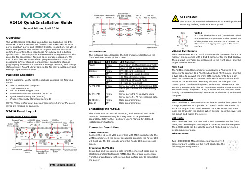
P/N: 1802024160011V2416 Quick Installation GuideSecond Edition, April 2014OverviewThe V2416 Series embedded computers are based on the Intel Atom N270 x86 processor and feature 4 RS-232/422/485 serial ports, dual LAN ports, and 3 USB 2.0 hosts. In addition, the V2416 computers provide VGA and DVI-I outputs and are EN 50155 certified to confirm their robustness for railway and industrialapplications. 2 hot-swappable and removable storage trays are also provided for convenient, fast and easy storage expansion. The V2416 also features user-defined programmable LEDs and an associated API for storage management, supporting storageplug/unplug functionality, automatic storage removal, and storage status display. An API Library is included for easy development and storage capacity notification.Package ChecklistBefore installing, verify that the package contains the following items:• V2416 embedded computer. • Wall mounting kit• PS2 to KB/MS Y-type cable• Documentation and Software CD or DVD • Quick installation guide (printed)• Product Warranty Statement (printed)NOTE: Please notify your sales representative if any of the above items are missing or damaged.V2416 Panel LayoutV2416 Front & Rear ViewsLED IndicatorsThe following table describes the LED indicators located on the front and rear panels of the V2416. LED Name LED Color LED FunctionPower Green Power is on and functioning normally OffPower is off, or power error exists Storage Yellow CF/HDD card is detectedOff CF/HDD card is not detected LAN (1, 2)Green 100 Mbps Ethernet mode Yellow1000 Mbps Ethernet mode Off 10 Mbps or no activityTx (P1-P4)Green Serial ports P1-P4 transmitting data Off Serial ports P1-P4 not transmitting dataRx (P1-P4) Yellow Serial ports P1-P4 receiving data Off Serial ports P1-P4 not receiving data X2 (Disk 1, Disk 2)Yellow User-programmable OffUser-programmableInstalling the V2416The V2416 can be DIN-rail mounted, wall mounted, and VESA mounted. Some mounting kits may need to be purchased separately. Refer to the Hardware User’s Manual for detailed installation instructions.Connector DescriptionPower ConnectorConnect the 12 to 48 VDC power line with M12 connectors to the V2416 computer. If the power is supplied properly, the Power LED will light up. The OS is ready when the Ready LED glows a solid green.Grounding the V2416Grounding and wire routing help limit the effects of noise due to electromagnetic interference (EMI). Run the ground connection from the ground screw to the grounding surface prior to connecting the power.V2416SG: The Shielded Ground (sometimes called Protected Ground) contact is the central pin of the power input connector. Connect the SG wire to an appropriate grounded metal surface.VGA and DVI OutputsThe V2416 comes with a D-Sub 15-pin female connector for a VGA monitor; it also comes with a DVI-I connector for the DVI display. These output interfaces are all located on the front panel. Use the proper cable to connect. PS/2 PortThe V2416 embedded computer comes with a PS/2 mini-DINconnector to connect to a PS/2 keyboard and PS/2 mouse. Use the Y-type cable to convert the mini-DIN connector into two 6-pin mini-DIN connectors to connect both a PS/2 keyboard and PS/2 mouse at the same time. You may also use the USB ports to connect your USB-based keyboard and mouse. Please note that without a Y-type cable, the PS/2 connector on the V2416 can only work with a PS/2 keyboard. A PS/2 mouse will not function when directly connected to the PS/2 connector on the V2416 embedded computer.CompactFlash SlotThe V2416 has a CompactFlash slot located on the front panel for storage expansion. It supports CF Type-I/II with DMA mode. To install a CompactFlash card, remove the outer cover, and then insert the CF card in the socket. When finished, push the cover into the socket and fasten the screws. USB HostsThe V2416 has one USB port with a M12 connector on the front panel, and two USB ports with type A connectors on the rear panel. These USB ports can be used to connect flash disks for storing large amounts of data. Ethernet PortsTwo 10/100/1000 Mbps Ethernet ports using M12 connectors are located on the front panel. See the following pin assignments./supportThe Americas: +1-714-528-6777 (toll-free: 1-888-669-2872)Europe: +49-89-3 70 03 99-0 Asia-Pacific: +886-2-8919-1230China: +86-21-5258-9955 (toll-free: 800-820-5036)2014 Moxa Inc., All Rights Reserved10/100 Mbps1000 MBps 1 -- TRD3+ 2 -- TRD4+ 3 -- TRD4- 4 ERx- TRD1- 5 ETx+ TRD2+ 6 ERx+ TRD1+ 7 -- TRD3- 8 ETx-TRD2-Serial PortsThe serial ports use DB9 connectors. Each port can be configured by software for RS-232, RS-422, or RS-485. The pin assignments for the ports are shown in the following table: Pin RS-232 RS-422 RS-485 (4-wire) RS-485 (2-wire) 1 DCD TxDA(-) TxDA(-) --- 2RxD TxDB(+) TxDB(+) ---3 TxD RxDB(+) RxDB(+) DataB(+)4 DTR RxDA(-) RxDA(-) DataA(-)5 GND GND GND GND6 DSR --- --- ---7 RTS --- --- --- 8CTS---------Audio InterfaceThe V2416 comes with an audio input and an audio output, allowing users to connect a speaker or an earphone. DI/DOThe V2416 comes with a 6-ch digital input and 2-ch digital output in the terminal block connectors.Hot-swappable and removable Storage TraysThe V2416 computers come with 2 removable slots for inserting additional storage media; it also supports hot swapping forconvenient, fast, and easy storage expansion. The user-defined programmable LEDs and the associated API for storagemanagement support storage plug/unplug functionality, automatic storage removal, and storage status display. Refer to the Hardware User's Manual for detailed storage installation. Reset ButtonPress the “Reset Button” on the rear panel of the V2416 to reboot the system automatically. The Ready LED will blink on and off for the first 5 seconds, and then maintain a steady glow once the system has rebooted.Real-time ClockThe V2416’s real-time clock is powered by a lithium battery. We strongly recommend that you do not replace the lithium battery without help from a qualified Moxa support engineer. If you need to change the battery, contact the Moxa RMA service team.Powering on the V2416To power on the V2416, connect the power cable to the V2416’s M12 power connector (located at the rear panel). Press the power button to turn on the computer. Note that the Shielded Ground wire should be connected to the central pin of the connector. It takes about 30 seconds for the system to boot up. Once the system is ready, the Power LED will light up.Configuring the Ethernet InterfacePower on the V2416 computer after connecting a monitor,keyboard, and mouse, and verifying that the power source is ready. Once the operating system boots up, the first step is to configure the Ethernet interface. The factory default settings for the V2416 LANs are show below. (Please note that the XPE and W7E models use DHCP settings.)Default IP Address NetmaskLAN1 192.168.3.127 255.255.255.0 LAN2 192.168.4.127255.255.255.0Linux users should follow these steps:If you are using the console cable for first-time configuration of the network settings, enter the following commands to edit the interfaces file:#ifdown –a//Disable LAN1/LAN2 interface first, before youreconfigure the LAN settings. LAN 1 = eth0, LAN 2= eth1,#vi /etc/network/interfaces//check the LAN interface first// After the boot settings of the LAN interface have been modified, use the following command to activate the LAN settings immediately:#sync; ifup –aXPE users should follow these steps:1. Go to Start Network Connections .2. Right-click Network Connections , click Properties . Next,select Internet Protocol (TCP/IP), and then click Properties .3. Click OK after inputting the proper IP address and netmask.W7E users should follow these steps:1. Go to Start -> Control Panel-> Network and Internet ->View network status and tasks -> Change adapter setting .2. In the screen of Local Area Connection Properties, clickInternet Protocol (TCP/IP) and then select Properties . Select Internet Protocol Version 4, and then click Properties .3. Click OK after inputting the proper IP address and netmask. NOTE: Refer to the User’s Manual for other configuration information.。
MxGPU设置指南说明书

DISCLAIMERThe information contained herein is for informational purposes only, and is subject to change without notice. While every precaution has been taken in the preparation of this document, it may contain technical inaccuracies, omissions and typographical errors, and AMD is under no obligation to update or otherwise correct this information. Advanced Micro Devices, Inc. makes no representations or warranties with respect to the accuracy or completeness of the contents of this document, and assumes no liability of any kind, including the implied warranties of non-infringement, merchantability or fitness for particular purposes, with respect to the operation or use of AMD hardware, software or other products described herein. No license, including implied or arising by estoppel, to any intellectual property rights is granted by this document. Terms and limitations applicable to the purchase or use of AMD’s products are as set forth in a signed agreement between the parties or in AMD's Standard Terms and Conditions of Sale.©2016 Advanced Micro Devices, Inc. All rights reserved. AMD, the AMD arrow, FirePro, and combinations thereof are trademarks of Advanced Micro Devices, Inc. in the United States and/or other jurisdictions. OpenCL is a trademark of Apple, Inc. and used by permission of Khronos. PCIe and PCI Express are registered trademarks of the PCI-SIG Corporation. VMware is a registered trademark of VMware, Inc. in the United States and/or other jurisdictions. Other names are for informational purposes only and may be trademarks of their respective owners.Table of Contents1.Overview (4)2.Hardware and Software Requirements (4)2.1Hardware Requirements (4)2.1.1Host/Server (4)2.1.2Client (4)2.2Software Requirements (5)3.MxGPU Setup (6)3.1Programming SR-IOV Parameters for MxGPU (6)3.2VF Pass Through (8)3.3VF-to-VM Auto-Assignment (9)4.Appendix (11)4.1Host Server Configuration (11)4.2Manual Installation for GPUV Driver for VMware ESXi (13)4.2.1Upload GPUV Driver (13)4.2.2Install GPUV Driver (13)4.2.3Configure GPUV Driver (15)4.2.4Un-Install GPUV Driver (16)4.2.5Update GPUV Driver (17)1.OverviewThis setup guide details the advanced steps necessary to enable MxGPU on the AMD FirePro™ S7100X, S7150 and S7150x2 family of products. The guide uses VMware® products as an example setup. These products include VMware ESXi™ as a hypervisor, the VMware vSphere® client and VMware Horizon® View™. The basic setup steps for the VMware software is detailed in the companion document to this one.2.Hardware and Software RequirementsThe sections below lists the hardware and software that are required for setting up the VMware environment.2.1Hardware Requirements2.1.1Host/ServerGraphics Adapter: AMD FirePro™ S7100X, S7150, S7150x2 for MxGPU and/orpassthrough***note that the AMD FirePro™ S7000, S9000 and S9050 can be used for passthroughonlySupported Server Platforms:•Dell PowerEdge R730 Server•HPE ProLiant DL380 Gen9 Server•SuperMicro 1028GQ-TR ServerAdditional Hardware Requirements:•CPU: 2x4 and up•System memory: 32GB & up; more guest VMs require more system memory•Hard disk: 500G & up; more guest VMs require more HDD space•Network adapter: 1000M & up2.1.2ClientAny of the following client devices can be used to access the virtual machine once theseVMs are started on the host server:•Zero client (up to 4 connectors) with standard mouse/keyboard and monitor•Thin client with standard mouse/keyboard and monitor running Microsoft®Windows® Embedded OS•Laptop/Desktop with standard mouse/keyboard and monitor running withMicrosoft® Windows® 7 and up2.2 Software RequirementsProductType Install OnSectionVersion/Download LocationAMD FirePro™ VIB Driver Hypervisor Driver Host (Server) 3.1 /en-us/download/workstation?os=VMware%20vSphere%20ESXi%206.0#catalyst-pro AMD VIB Install Utility Script Host (Server) 3.1 /en-us/download/workstation?os=VMware%20vSphere%20ESXi%206.0#catalyst-pro PuTTYSSH client Host Admin. System / SSH Secure ShellSSH Client andDownload UtilityHost Admin. System3.1Table 1 : Required Software for Document(Links to non-AMD software provided as examples)3.MxGPU SetupThe following sections describe the steps necessary to enable MxGPU on the graphics adapter(s) in the host. Before proceeding, refer to the Appendix to ensure that the host system is enabled for virtualization and SR-IOV. Once virtualization capabilities are confirmed for the host system, follow the steps in the next two sections to program the graphics adapter(s) for SR-IOV functionality and to connect the virtual functions created to available virtual machines.3.1Programming SR-IOV Parameters for MxGPU1.Download and unzip the vib and MxGPU-Setup-Script-Installer.zip from Table 1.2.Copy script and vib file to the same directory (Example : /vmfs/volumes/datastore1)ing an SSH utility, log into the directory on the host and change the attribute of mxgpu-install.sh to be executable # chmod +x mxgpu-install.sh4.Run command: # sh mxgpu-install.sh to get a list of available commands5.Run command: # sh mxgpu-install.sh –i <amdgpuv…vib>•If a vib driver is specified, then that file will be used. If no vib driver is specified then the script assumes the latest amdgpuv driver in the current directory•The script will check for system compatibility before installing the driver•After confirming system compatibility, the script will display all available AMD adapters7.Next, the script will show three options: Auto/Hybrid/Manual.1)Auto: automatically creates a single config string for all available GPUs:•the script first prompts for the number of virtual machines desired (per GPU) and sets all settings accordingly (frame buffer, time slice, etc…)•next, the script prompts the user if they want to enable Predictable Performance, a feature that keeps performance fixed independent of active VMs•the settings are applied to all AMD GPU available on the bus•if a S7150X2 is detected, the script will add pciHole parameters to VMs• a reboot is required for the changes to take effect2)Hybrid: configure once and apply to all available GPUs:•the script first prompts for the number of virtual machines desired (per GPU) and sets all settings accordingly (frame buffer, time slice, etc…)•next, the script prompts the user if they want to enable Predictable Performance•the settings are applied to the selected AMD GPU; the process repeats for the next GPU•if a S7150X2 is detected, the script will add pciHole parameters to VMs• a reboot is required for the changes to take effect3)Manual: config GPU one by one:•the script prompts the user to enter VF number, FB size/VF, time slice•next, the script prompts the user if they want to enable Predictable Performance•the settings are applied to selected AMD GPU; the process repeats for the next GPU•if a S7150X2 is detected, the script will add pciHole parameters to VMs• a reboot is required for the changes to take effectFigure 1 : Screenshot of MxGPU Setup Script Installation FlowFor users who want to understand the individual steps required for vib installation and configuration,3.2VF Pass ThroughOnce the VFs (virtualfunctions) are set up, thenpassing through theses VFsfollows the same procedureas passing through a physicaldevice. To successfully passthrough the VFs, the physicaldevice CANNOT beconfigured as a passthroughdevice. If the physical deviceis being passed through tothe VM, then the GPUVdriver will not install properly.If that happens, the VFs willnot be enabled and no VFswill be shown.Once the VFs are enabled, they will be listed in the available device list for pass through, and the status of the PF will be changed to unavailable for pass through. No additional operation is needed to move VF into pass through device list.3.3VF-to-VM Auto-Assignment1.After rebooting the system and the VFs are populated on the device list, navigate to thedirectory containing the mxgpu-install.sh script2.Specify Eligible VMs for auto-assign in “vms.cfg” file•Note: If all registered VMs should be considered eligible, skip to step 43.Edit vms.cfg file to include VMs that should be considered for auto-assign•Use # vi vms.cfg to edit the configuration file•For help with using vi, an example can be found on the following VMware page: https:///selfservice/microsites/search.do?language=en_US&cmd=displayKC&externalId=1020302•Examples are provided in the vms.cfg configuration file on how to specify VMs should be considered eligible•Note: Make sure to delete the regular expression .* if you are specifying your own VMs4.Start the auto-assign option # sh mxgpu-install.sh –a5.Select the command to execute [assign|unassign|list|help]6.The assign command will continue if the number of eligible VMs does not exceed the number ofVFs7.Once the VM is powered on, a VF will appear in the Device Manager as a graphics device. Thegraphics driver can now be installedFigure 2 : Screenshot of the default contents of “vms.cfg” fileFigure 3 : Screenshot of Multi-Assign UsageFigure 4 : Screenshot of Multi-Assign “list” command after assigning VFs to VMs4.Appendix4.1Host Server ConfigurationTo enable the MxGPU feature, some basic virtualization capabilities need to be enabled in the SBIOS. These capabilities may be configured from the SBIOS configuration page during system bootup. Different system BIOS vendors will expose different capabilities differently. Some may have one control that enables a number of these capabilities. Some may expose controls for some capabilities while hardcoding others. The following settings, taken from an American Megatrends system BIOS, provides a list of the minimal set of capabilities that have to be enabled :Server CPU supports MMUServer chipset supports AMD IOMMU or Intel VT-dThe option “Intel VT for Directed I/O (VT-d)” should be enabledExample Path : IntelRCSetup → IIO Configuration → Intel(R) VT for Directed I/O (VT-d) → Intel VT for Directed I/O (VT-d)Server (SBIOS) support PCIe standard SR-IOVThe option “SR-IOV Support” should be enabled.Example Path : Advanced → PCI Subsystem Settings → SR-IOV SupportServer (SBIOS) support ARI (Alternative Routing ID)The option “ARI Forwarding” should be enabled.Example Path : Advanced → PCI Subsystem Settings → PCI Express GEN 2 Settings → ARI ForwardingServer (SBIOS and chipset (root port/bridge)) supports address space between 32bit and 40bitIf there is an “Above 4G Decoding” enable it.Example Path : Advanced → PCI Subsystem Settings → Above 4G DecodingServer (Chipset (root port / bridge)) supports more than 4G address spaceThere may be an option “MMIO High Size” for this function (default may be 256G).Example Path : IntelRCSetup → Common RefCode Configuration → MMIO High Size Examples on the next page demonstrate implementations from other system BIOS vendors.The following example showshow to enable SR-IOV on a Dell R730 platform.On some platforms, theSBIOS configuration page provides more options to control the virtualization behavior. One of these options is the ARI (alternative reroute interface) as shown below.In addition, some platformsalso provide controls to enable/disable SVM and/or IOMMU capability. These options must be enabled on the platform.4.2Manual Installation for GPUV Driver for VMware ESXi *note that the GPUV driver refers to the vib driver.4.2.1Upload GPUV Driver1.Download the GPUV driver to the administrator system from Table 1.2.Start SSH Secure File Transfer utility and connect to the host server.3.On the left (theadministratorsystem), navigate tothe directory wherethe GPUV driver issaved; on the right(the host system),navigate to/vmfs/volumes/datastore14.Right click on the GPUV driver file and select “Upload” to upload it to/vmfs/volumes/datastore1.4.2.2Install GPUV Driver1.In vSphere client, place system into maintenance mode2.Start SSH Secure Shell client, connect to host, run the following command:esxcli software vib install --no-sig-check -v /vmfs/volumes/datastore1/amdgpuv-<version>.vib ***note : the vib name is used as an example.You should seesomething this :3.In the vSphere client, exit maintenance mode4.In SSH Secure Shell client window, run the following command :esxcli system module set -m amdgpuv -e trueThis command makes theamdgpuv driver load on ESXiboot up.5.In vSphere client, reboot the server.4.2.3Configure GPUV Driver1.Find out the BDF (bus number, device number, and function number) of the SR-IOV adapter. InSSH Secure Shell client , type in command :lspciYou should see somethinglike in the picture. The BDFfor this adapter is 05.00.0 inthis example.2.In SSH Secure Shell client window run the following command to specify the setting for SR-IOVadapter:esxcfg-module –s “adapter1_conf=<bus>,<dev>,<func>,<num>,<fb>,<intv>” amdgpuvThe configuration is done through esxcfg-module command in the format of parameter as [bus, dev, func, num, fb, intv] to quickly set all VFs on one GPU to the same FB size and time slice.•bus – the bus number: in decimal value•dev – the device number: in decimal value•func – the function number•num – the number of enabled VFs•fb – the size of framebuffer for each VF•intv – the interval of VF switching.For example,•command: esxcfg-module -s "adapter1_conf=1,0,0,15,512,7000" amdgpuv Enables 15 virtual functions, each VF with 512M FB, and 7 millisecond time slice for*******************************.0•command: esxcfg-module -s "adapter1_conf=5,0,0,8,256,7000adapter2_conf=7,0,0,10,256,10000" amdgpuvEnable 8 VF, each VF has 256M FB and 7 millisecond time slice for adapter located @05:00.0Enable 10 VF, each VF has 256M FB and 10 millisecond time slice for adapter located @07:00.0•command: esxcfg-module -s "adapter1_conf=14,0,0,6,1024,7000adapter2_conf=130,0,0,4,1920,7000" amdgpuvEnable 6 VF, each VF has 1024M FB and 7 millisecond time slice for adapter located @0E:00.0Enable 4 VF, each VF has 1920M FB and 7 millisecond time slice for adapter located @82:00.0Note:1)Every time the command is executed, the previous configuration is overwritten. If the userwants to configure a newly added GPU, he needs to apply the previous parameterappending with new parameter in one command, otherwise the previous configuration for the existing GPU is lost.2)If you use lspci to find out the BDF of the GPU location, the value is in hex value instead ofdecimal value. In the last example, the first adapter is located at bus 14, but the lspci willshow as 0E:00.0; the second adapter is located at bus 130, the lspci will show as 82:00.0.3.In order to let the new configuration take effect, a server reboot is needed - in vSphere client,reboot the server.4.2.4Un-Install GPUV Driver1.Unload the GPUV driver by typing in command in SSH Secure Shell client :vmkload_mod -u amdgpuv2.In vSphere Client, set system to maintenance mode3.In SSH Secure Shell client type in command :esxcli software vib remove -n amdgpuv4.Start SSH Secure FileTransfer utility,connect to hostserver. On the right(the host system),navigate to/vmfs/volumes/datastore1, select theamdgpuv driver,right click, select“Delete”.5.In vSphere client, reboot the server.4.2.5Update GPUV Driver1.Follow the sequence in section 4.2.4 to remove the old driver.2.Follow the sequence in section 4.2.1 to download the new driver3.Follow the sequence in section4.2.2 to install the new driver4.Follow the sequence in section 4.2.3 to configure the new driver.。
Arduino UNO R4 MiniMA ABX00080说明书

1122334455667788DDCCBBAAReference Designs ARE PROVIDED "AS IS" AND "WITH ALL FAULTS. Arduino SA DISCLAIMS ALL OTHER WARRANTIES, EXPRESS OR IMPLIED, REGARDING PRODUCTS, INCLUDING BUT NOT LIMITED TO, ANY IMPLIED WARRANTIES OF MERCHANTABILITY OR FITNESS FOR A PARTICULA R PURPOSE.Arduino SA may make changes to specifications and product descriptions at any time, without notice. The Customer must not rely on the absence or characteristics of any features or instructions marked "reserved" or "undefined".Arduino SA reserves these for future definition and shall have no responsibility whatsoever for conflicts or incompatibilities arising from future changes to them. The product information on the Web Site or Materials is subject to change without notice.Do not finalize a design with this info. ARDUINO and other Arduino brands and logos and Trademarks of Arduino SA. All Arduino SA Trademarks cannot be used without owner's formal permission.11UNO R4 MINIMA ABX00080V1.04/24/20233:04:30 PM Title:ID:Date:Version:Sheet of Time:Silvio NavarettiAuthor:RevAuthor:Silvio NavarettiTOP.SchDocFile:330R14330R15DL1KPT-1608YC YELLOWDL2KPT-1608YC TX LED RX LED MICROCONTROLLER330R16DL3HSMG-C190POWER LED+5VP012YELLOWFiducial_1Fiducial_2GREENP400/GTIOC6A1P401/GTIOC6B/CTX02P402/CRX03VBATT 4VCL5P215 INPUT ONL Y/XCIN 6P214 INPUT ONL Y/XCOUT7VSS 8P213/GTIOC0A/XTAL 9P212/GTIOC0B/EXTAL10VCC 11P411/GTIOC6A12P410/GTIOC6B 13P409/GTIOC5A/USB_EXICEN 14P408/GTIOC5B/USB_ID15P407/USB_VBUS/ADTRG016VSS_USB 17P915/USB_DM 18P914/USB_DP19VCC_USB20VCC_USB_LDO 21P20622GTIOC4A/P20523GTIOC4B/P20424RES25MD/P20126NMI/INPUT ONL Y P20027GTIOC7A/P30428GTIOC7B/P30329GTIOC4A/P30230GTIOC4B/P30131P300/GTIOC0A/TCK/SWCLK 32P108/GTIOC0B/TMS/SWDIO 33CTX0/TDO/SWO/GTIOC1A/P10934CRX0/TDI/GTIOC1B/P11035GTIOC3A/P11136GTIOC3B/P11237GTIOC2A/P11338VCC 39VSS40GTIOC0A/P10741GTIOC0B/P10642GTIOC1A/P10543GTIOC1B/P10444GTIOC2A/AN019/P10345ADTRG0/GTIOC2B/AN020/P10246GTIOC5A/AN021/P10147GTIOC5B/AN022/P10048GTIOC2A/AN016/P50049GTIOC2B/AN017/P50150GTIOC3B/AN018/P50251AN010/P01552DA0/AN009/P01453VREFL/AN008/P01354VREFH/AN007/P01255AVCC056AVSS057VREFL0/AN006/P01158P010/AN005/VREFH059AN004/P00460AN003/P00361AN002/P00262AN001/P00163AN000/P00064U1R7FA4M1AB3CFM#AA0USB_D_N USB_D_P15pFC113N C2N C4Y1FTX16.000M12SM3S-30/3015pFC3RESET +5V 4.7µFC4100nF C5100nFC6VCC_USB is the output of theinternal USB LDO providing 3V3 to the peripheralRefer to figure 26.4 page 555 of the user manual4.7µFC7AREF+5VL1BLM18PG471SN1D5.1kR4VREFH01µFC9L2BLM18PG471SN1D100nF C8VCL is the output of the internal LDO4.7µFC11RESET PUSHBUTTONHEADERS+5V+5VUSB5.1kR1 5.1kR25.1kR3SCL18SDA 17AREF 16GND 15D13/SCK 14D12/MISO 13D11/MOSI 12D10/CS11D910D89D78D67D56D45D34D23D1/TX 2D0/RX1JDIGITAL20TW-994C2DNP12345PB11571636-3AREFNC 1IOREF 2RESET 33V345V5GND6GND7VIN 8A09A110A211A312A413A514JANALOG20TW-995RESET RESET112233445566J1PH2-06-UA+5V P013USB CONNECTORSHIELD1GNDB12VBUS B9SBU2B8D-B7D+B6CC2B5VBUS B4GND B1GND A12VBUSA9SBU1A8D-A7D+A6CC1A5VBUS A4GND A1FIXING A12A1B12B1SHIELD2SHIELD3SHIELD4J3CX90B-16P VBUS_CONN CC1USB_D_PUSB_D_N D-USB USB_D_N USBUSB_D_P D+CC2GND21MR231kV4.7nFC21ESDPROTECTION2341D4PRTR5V0U2X,215SHIELD2CC RESISTORS CC2CC15.1kR24 5.1kR25123J419TW-746+5VUSB LDO OUTPUT+3V3100nF C10+5VVINDC SHIELD2USB_D_N USB_D_P SWD CONNECTOR12345678910J2HPH2-A-10-SGARESET +5VRXTX RTS CTSSCI15.1kR75.1k R85.1kR9P012P0135.1kR5 5.1kR6INPUT ONLY+3V3VIN DAC OPAMP+P000_AN00_AMP+OPAMP-OPAMP OUT P014_AN09_DAC P001_AN01_AMP-P002_AN02_AMPO P101_AN21_SDA P100_AN22_SCL P000_AN00_AMP+P001_AN01_AMP-P002_AN02_AMPOP014_AN09_DACP100_AN22_SCL P101_AN21_SDA P100_AN22_SCL P101_AN21_SDAP301_SCI2_RXDP302_SCI2_TXD P301_SCI2_RXD P302_SCI2_TXD I2C PULLUPSNOT MOUNTEDP105_IRQ00_GPT1_A P105_IRQ00_GPT1_A DL4KPT-1608YC YELLOW 330R17SCK LEDP104_IRQ01_GPT1_B P104_IRQ01_GPT1_B P103_SPI0_SSL_GPT2_A_CAN0_TX P103_SPI0_SSL_GPT2_A_CAN0_TX P102_SPI0_RSPCK_GPT2_B_CAN0_RX P102_SPI0_RSPCK_GPT2_B_CAN0_RX P106_GPT0_BP106_GPT0_B P107_GPT0_A P107_GPT0_AP304_GPT7_A P304_GPT7_AP303_GPT7_B P303_GPT7_B P112_GPT3_BP112_GPT3_B P109_SCI9_TXD P109_SCI9_TXD P109_SCI9_TXDP110_SCI9_RXD P110_SCI9_RXD P 110_S C I 9_R X DP111_GPT3_A P111_GPT3_A P 111_G P T 3_AP111_GPT3_AP108_SWDIO P300_SWCLK P108_SWDIOP300_SWCLK P501_SCI1_TXD P502_SCI1_RXDP501_SCI1_TXDP502_SCI1_RXD +5VMD MDVUSBDCJACKBUCKCONVERTERSCHOTTKY FORREVERSE POLARITY PROTECTIOND3PMEG6020AELRXD2PMEG6020AELRXSS 1SYNC2BOOT 3VIN 4PHASE5PGND 6EN 7PG 8VCC 9FB 10COMP11FS12GNDPAD13U2ISL854102FRZ-T +5V2.3A 10µH L3PMF42-103MN100nF C1225V 22µF C130R12100kR1325V22µFC1825V 22µF C1525V 22µF C1633pF C1425V 22µF C171µFC2025V22µF C1913.7kR180R20249kR19100kR21100kR221nFC22100pFC23+5V+5V VUSB VUSB VUSBVUSB VUSB 0R11100k 0.1%R1013.7k 0.1%R26+5VSCHOTTKY FOR USB OVERVOL TAGE PROTECTIONP204LOVE。
富士通不间断在线电源供应(UPS)电源保护数据表说明书

Data SheetFUJITSU Uninterruptible Online Power Supply (UPS) Power ProtectionPower supply protection for systems and data – powerful andreliable (APC SURT Gen2)Fujitsu Technology Solutions UPS devices ensure high-performance power supply protection for systems and data, and thus provide reliable protection against power failure, currentfluctuations and electrical interference. Fujitsu Technology Solutions offers both line interactive and online devices. Capacities of up to 10kVA provide the right power supply and technology for all individual requirements.The use of uninterruptible power supplies can particularly benefit your company from a financial viewpoint: Having to search for and restore lost or damaged data after a power failure can cost a great deal of time and money. In such incidents UPS helps to protect your data.Uninterruptible Online Power Supply (UPS) Fujitsu Technology Solutions VFI (Voltage and Frequency Independent) online UPS devices from APC are the only UPS devices to offer protection against all kinds of faults, such as power failures, frequency fluctuations, voltage swings and peaks as well as low voltage and surges. They also have precise frequency and voltage regulation as well as the Smart Slot interface for integration into SNMP-based network management. Another outstanding feature is the ability to replace used or faulty batteries during ongoing operation without any interruption. All these APC UPS devices can be converted for installation in racks / towers.Fujitsu Technology Solutions not only offerscustomers a 3-year manufacturer’s warranty (door to door) on the UPS and the batteries, but also optimal integration of the control software into the network management solution ServerView Suite. Support of Windows / Linux and SOLARIS operating systems as well as virtualization layers is provided. In contrast to the VI (Voltage Independent) line interactive and VFD (Voltage and Frequency Dependent) offline versions, the output frequency of the VFI UPS devices is totally independent of any mains, voltage and frequency changes. The mains voltage is permanently rectified in order to then be inverted back to alternating voltage. Hence the rectifierinverter combination, which achieves a constant power supply and a high filter effect. The VFI UPSdevices also have a parallel bypass switch whichcompensates for overloads in problem situations.Technical detailsTechnical detailsPY Online UPS 10kVA /10kWPY Online UPS 3kVA / 2,7W PY Online UPS 5kVA / 4,5kW PY Online UPS 8kVA / 8kWInput voltage220V - 240V 1-phase380V - 415V 3-phase 220V - 240V 1-phase220V - 240V 1-phase380V - 415V 3-phaseInput frequency50Hz / 60Hz Output voltage230 VUPS Slots 1 smart card slot (free)Input connections Hardwire 3-wire (1Ph+N+G)Hardwire 3-wire (2Ph+G)Hardwire 5-wire (3Ph+N+G)Dual Input for bypassing feature Hardwire 3-wire (1Ph+N+G)Hardwire 3-wire (1Ph+N+G)Hardwire 3-wire (2Ph+G)Hardwire 5-wire (3Ph+N+G)Dual Input for bypassingfeatureUPS Notes Integrated SNMP WEB management interface (Serial interface is not supported) APC SW, cable and manuals Interfaces Integrated WEB management interfaceHigh Resolution Graphical LCD displayOutput connections SOG #1: 6x IEC 320 C13 (10A)SOG #2: 2x IEC 320 C19 (16A)SOG #3: 2x IEC 320 C19 (16A)MOG HW 3-Wire (L+N+G)SOG #1: 6x IEC 320 C13(10A)SOG #2: 4x IEC 320 C19(16A)SOG #1: 6x IEC 320 C13(10A)SOG #2: 2x IEC 320 C19(16A)SOG #3: 2x IEC 320 C19(16A)MOG HW 3-Wire (L+N+G)Output connection notes Switched Outlet Group(s) : Ability to control a group of output load receptacles independent from the main UPSInput protection80A 1-phase (and L1 respectively)25A 3-phase (L2 / L3)32A 1-phase63A 1-phase (and L1respectively)20A 3-phase (L2 / L3)UPS Battery Pack External runtime extensionfor APC Online (VFI) UPS- 5 kVA (3U rack version);Size (HxWxD) / Weight 130 x432 x 640 mm / 80 kg- 8 to 10 kVA (3U rackversion); Size (HxWxD) /Weight 30 x 432 x 640 mm/ 80 kg- Cable to connect UPS andextension battery are partof the delivery External runtime extensionfor APC Online (VFI) UPS- 3 kVA (2U rack version);Size (HxWxD) / Weight yyy xyyy x yyy mm / yy kg- 5 kVA (3U rack version);Size (HxWxD) / Weight 130 x432 x 640 mm / 80 kg- 8 to 10 kVA (3U rackversion); Size (HxWxD) /Weight 30 x 432 x 640 mm/ 80 kg- Cable to connect UPS andextension battery are partof the deliveryExternal runtime extension for APC Online (VFI) UPS- 5 kVA (3U rack version); Size (HxWxD) / Weight 130 x 432x 640 mm / 80 kg- 8 to 10 kVA (3U rack version); Size (HxWxD) / Weight 30 x432 x 640 mm / 80 kg- Cable to connect UPS and extension battery are part ofthe deliveryBattery runtime half load11.5 min11.8 min14.8 min Battery runtime full load 3.8 min 4 min 5.3 min Weight112 kg55 kg112 kgOperating systemCertified or supported operating systemsand virtualization softwareSoftware Support PowerChute Network Shutdown (for more detailed information please look at the software support matrix on the“APC by Schneider Electric” website)Order code Product NameA3C40178823PY Online UPS S2 3kVA R/TOrder code Product NameA3C40178825PY Online UPS 5kVA R/TA3C40178826PY Online UPS 8kVA R/TA3C40178827PY Online UPS 10kVA R/TApprovals & Conformity (Standards)Europe CEGlobal CBCompliance link https:///sites/certificatesWarrantyWarranty period 3 years (depending on country)Warranty type Door-to-Door Exchange ServiceProduct Support - the perfect extensionSupport Pack Options Globally available in major metropolitan areas:9x5, Next Business Day Onsite Response Time9x5, 4h Onsite Response Time (depending on country)24x7, 4h Onsite Response Time (depending on country) Recommended Service-Service Weblink https:///emeia/support/ContactFujitsu LIMITED Website: 2023-09-02 WW-ENworldwide project for reducing burdens on the environment.Using our global know-how, we aim to contribute to the creation of a sustainable environment for future generations through IT.Please find further information at http://www./global/about/environmenttechnical specification with the maximum selection of components for the named system and not the detailed scope ofdelivery. The scope of delivery is defined by the selection of components at the time of ordering. The product was developed for normal business use.Technical data is subject to modification and delivery subject to availability. Any liability that the data and illustrations are complete, actual or correct is excluded. Designations may be trademarks and/or copyrights of the respective owner, the use of which by third parties for their own purposes may infringe the rights of such owner.More informationAll rights reserved, including intellectual property rights. Designations may be trademarks and/or copyrights of therespective owner, the use of which by third parties for their own purposes may infringe the rights of such owner. For further information see https:///global/about/resources/terms/ Copyright 2023 Fujitsu LIMITED。
ArmorBlock LP2 4输入4输出模块(分类号:1792D-4BT4LP)说明书
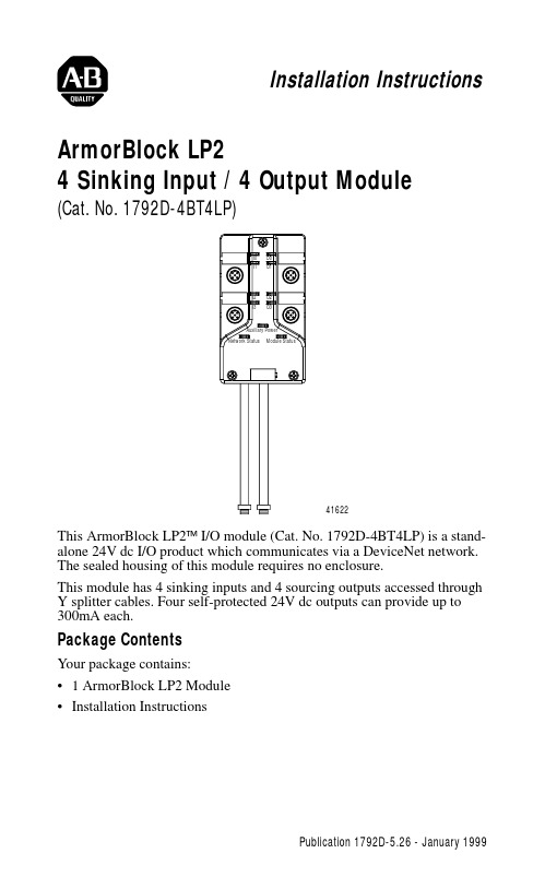
Installation InstructionsArmorBlock LP24 Sinking Input / 4 Output Module(Cat. No. 1792D-4BT4LP)This ArmorBlock LP2™ I/O module (Cat. No. 1792D-4BT4LP) is a stand-alone 24V dc I/O product which communicates via a DeviceNet network. The sealed housing of this module requires no enclosure.This module has 4 sinking inputs and 4 sourcing outputs accessed through Y splitter cables. Four self-protected 24V dc outputs can provide up to 300mA each.Package ContentsYour package contains:• 1 ArmorBlock LP2 Module •Installation Instructions416222 4 Sinking Input / 4 Output ModuleEuropean Union Directive ComplianceIf this product has the CE mark it is approved for installation within the European Union and EEA regions. It has been designed and tested to meet the following directives.EMC DirectiveThis product is tested to meet Council Directive 89/336/EEC Electromagnetic Compatibility (EMC) and the following standards, in whole or in part, documented in a technical construction file:•EN 50081-2 EMC - Generic Emission Standard, Part 2 - Industrial Environment•EN 50082-2 EMC - Generic Immunity Standard, Part 2 - Industrial EnvironmentThis product is intended for use in an industrial environment.Low Voltage DirectiveThis product is tested to meet Council Directive 73/23/EEC Low V oltage, by applying the safety requirements of EN 61131-2 Programmable Controllers, Part 2 - Equipment Requirements and Tests.For specific information required by EN 61131-2, see the appropriate sections in this publication, as well as the following Allen-Bradley publications:•Industrial Automation Wiring and Grounding Guidelines For Noise Immunity, publication 1770-4.1•Automation Systems Catalog, publication B111Install Your ArmorBlock LP2 I/O ModuleTo install the module:•Set the node address and baud rate.•Mount the module.•Connect the unit to the DeviceNet trunk and the auxilary power source.•Connect the cord sets.Set the Node AddressSet the node address using RSNetworx for DeviceNet software, DeviceNetManager™ software, or another software configuration tool. The module is equipped with AutoBaud detect. AutoBaud lets the module read the settings already in use on your DeviceNet network and automatically adjusts to follow those settings.4 Sinking Input / 4 Output Module3Install the Module1.Attach the module using the dimensions shown below.2.Connect the grey DeviceNet cable to the DeviceNet trunk. Use the1485P-P1R5-MN5R1 T-Part tap to connect to round media. Use the 1485P-P1E4-R5 to connect to the Kwik Link flat media system. Connect the Input / Output Cord Sets to the LP2 ModuleThis module uses 5 pin micro (12mm) style PCB mounted connectors. Four micro caps cover the connectors on your module. Remove the caps and connect your cord sets to the appropriate ports. This product has two inputs or outputs per I/O connector. Use a “Y” splitter cable for access to all I/O connections. For more information on these cables, see the Product Data guide publication 1792-2.1.Use the micro caps to cover and seal unused ports. Pinout diagrams for the connectors are shown next.Input Micro-Connector(View into Sockets)Pin 1 Sensor Source VoltagePin 2 Input BPin 3 Return Logic Ground1Pin 4 Input APin 5 Not UsedOutput Micro-Connector(View into Sockets)Pin 1 Not UsedPin 2 Output BPin 3 Auxilary Power GroundPin 4 Output APin 5 Not UsedLogic Ground is approximately 0.4V above DeviceNet V-measured at the module.414524 4 Sinking Input / 4 Output ModuleOutput Power and DeviceNet CablesRefer to the DeviceNet Cable Planning and Installation Manual for more information on output power and DeviceNet cables for your application.!ATTENTION:•Make sure to connect the proper color coded cables together. DeviceNet cable should connect to DeviceNet cables and auxillary outputs should match auxillary outputs.•Make sure all connectors and caps are securely tightened to properly seal the connections against leaks and maintain IP67 requirements•For maximum noise immunity, input and output cable return wires must be properly terminated. When inputs and outputs are connected in loopback, return wires should be connected together.•I/O cable length should be less than 30 meters.Input 030706-MInput 1Input 2Input 34 Sinking Input / 4 Output Module 5Communicate With Your ArmorBlock LP2 I/O ModuleThis ArmorBlock module’s I/O is exchanged with the master through a polled, change of state, or cyclic connection.The module consumes and produces I/O data as follows:Cyclic - allows configuration of the block as an I/O client. The block will produce and consume its I/O cyclically at the rate configured.Polled - a master initiates communication by sending its polled I/O message to the module. The 4 input / 4 output module consumes themessage, updates outputs, and produces a response. The response has input data, and the status of the Auxiliary power.Change of state - productions occur when an input changes. If no input change occurs within the expected packet rate, a heartbeat production occurs. This heartbeat production tells the scanner module that the I/O module is alive and ready to communicate. Consumption occurs when data changes and the master produces new output data to the I/O module. Refer to the table below for the word/bit definitions.Type of I/O Connections Consumes Produces Cyclic 1 Byte 1 Byte Polled 1 Byte 1 Byte Change of State1 Byte1 ByteBit 0706050403020100Produces 0RSVD OPWR RSVD RSVD I3I2I1I0Consumes 0RSVDRSVDRSVDRSVDO3O2O1O0Where:RSVD= Reserved I = InputO = OutputOPWR= Output Power (Auxiliary Power)6 4 Sinking Input / 4 Output ModuleThe DeviceNet Network uses advanced network technology, producer/consumer communication, to increase network functionality andthroughput. Visit our web site at /networks for producer/consumer technology information and updates.Byte Bit DescriptionProduces 000-0304050607Input status bits: When the bit is set (1), the input is on. Bit 00 corresponds to input 0, bit 01 corresponds to input 1, bit 02 corresponds to input 2, bit 03 corresponds to input 3.Reserved ReservedOutput Powr Fault (OPWR): When the bit is set (1) auxilary power is not present.ReservedConsumes 000-0304-07Output bits: When the bit is set (1), the output will be turned on. Bit 00 corresponds to output 0, bit 01 corresponds to output 1, bit 02 to output 2, bit 03 to output 3.Reserved4 Sinking Input / 4 Output Module7Troubleshoot with the IndicatorsThis module has the following indicators:•Network status indicator•Module status indicator•Auxiliary Power indicator•Individual point status indicators for inputs 0, 1, 2, and 3 and outputs 0,Module Status IndicatorIndication StatusNone No PowerGreenBlinking Solid Needs Commissioning Operating NormalRedBlinking Solid Recoverable Fault Unrecoverable Faultand 130706-M 38 4 Sinking Input / 4 Output ModuleFor more information on indications see the Product Data publication 1792-2.1.Network Status Indicator Indication Status None Not On-lineGreen Blinking Solid On-line/No Connections On-line/ConnectedRed Blink SolidConnection Timed OutFailed Communication: A duplicate node address exists or module is at the wrong baud rate.Auxiliary Power Indication StatusNone No Auxiliary Power Green SolidAuxiliary Power PresentI/O Status Indicators Function Module Status Indicator Point Indicator Condition Outputs Green Green None Yellow Output not energized Output energized InputsGreen GreenNone YellowNo valid input Valid input4 Sinking Input / 4 Output Module9 Specifications4 Input / 4 Output Module - Cat. No. 1792D-4BT4LPSinking Input Specifications Max MinInputs per block 4 - 3 wire or dry contact PNP devices or 2 - 4 wirePNP devicesSensor Source Current (per input)50mA-On-state Voltage 25V dc10V dcOn-state Current10mA2mAOff-state Voltage5V dcOff-state Current 1.5mA Sourcing Output Specifications Max MinOutputs per block 4 sourcing outputs labeled O0, O1, O2, and O3 Output Auxiliary Voltage30V10VOn-state Voltage Drop1V-On-state Current0.3A-Off-state Leakage 1.5mA-Module Current (all outputs) 1.2A-Surge Current - for 10ms,repeatable every 2s0.6A-No Load Sense Current (On-state)0.18A-General SpecificationsIndicators Network Status - red/greenModule Status - red/greenAuxiliary Power - greenPoint LED - yellowCommunication Rate•125Kbps @ 500 meters(1600 feet) for thickcable, flat media length 375 meters•250Kbps @ 200 meters(600 feet) for thick cable,flat media length 150 meters• 500Kbps @ 100 meters (330 feet) for thickcable, flat media length 75 metersDeviceNet Power Voltage Current25V dc125mA (no sensors)300mA (full load)11V dcAuxiliary Power Voltage Current30V dc1.2A max10V dc1.2A maxDimensions (assembled to base) inches - (Millimeters)1.023H x 2.7w x 4.72D (26)H x (68.5)W x (120)D10 4 Sinking Input / 4 Output ModuleThis product has been tested at an Open DeviceNet V endor Association, Inc. (ODV A) authorized independent test laboratory and found to comply with ODV A Conformance Test Software Composite Test Version 11.ArmorBlock, ArmorBlock LP2 and DeviceNetManager are trademarks of Rockwell Automation.4 Input / 4 Output Module - Cat. No. 1792D-4BT4LP General Specifications Cont.MaxMinEnvironmental Conditions Operational Temperature Storage Temperature Relative Humidity Shock Operating Non-operating Vibration -25 to 60o (-13 to 140o F)-25 to 80o C (-13 to 176O F)Up to 100%30g peak acceleration, 11 (+1) ms pulse width 50g peak acceleration, 11(+1)ms pulse width Tested 10g @ 10-500Hz per IEC 68-2-6Conductors Publication DN-6.7.2EnclosureMeets or exceeds IP67Agency Certification(when product is marked)•CE marked for all applicable directives4 Sinking Input / 4 Output Module11Publication 1792D-5.26 - January 199912 4 Sinking Input / 4 Output ModulePublication 1792D-5.26 - January 1999PN 955134-80© 1999 Rockwell International. All Rights Reserved. Printed in USA。
Silicon Labs CP210x USB-to-UART 驱动程序下载与安装指南说明书
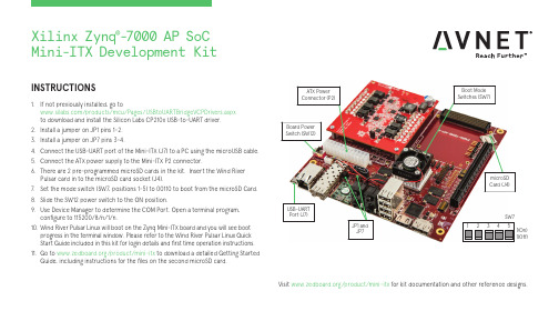
INSTRUCTIONS1. If not previously installed, go to /products/mcu/Pages/USBtoUARTBridgeVCPDrivers.aspx to download and install the Silicon Labs CP210x USB-to-UART driver.2. Install a jumper on JP1 pins 1-2.3. Install a jumper on JP7 pins 3-4.4. Connect the USB-UART port of the Mini-ITX (J7) to a PC using the microUSB cable.5. Connect the ATX power supply to the Mini-ITX P2 connector.6. There are 2 pre-programmed microSD cards in the kit. Insert the Wind River Pulsar card in to the microSD card socket (J4).7. Set the mode switch (SW7, positions 1-5) to 00110 to boot from the microSD Card.8. Slide the SW12 power switch to the ON position.9. Use Device Manager to determine the COM Port. Open a terminal program, configure to 115200/8/n/1/n.10. Wind River Pulsar Linux will boot on the Zynq Mini-ITX board and you will see boot progress in the terminal window. Please refer to the Wind River Pulsar Linux Quick Start Guide included in this kit for login details and first time operation instructions.11. Go to /product/mini-itx to download a detailed Getting Started Guide, including instructions for the files on the second microSD card.Visit /product/mini-itx for kit documentation and other reference designs.1(Off)1(On)JP1 and JP7Xilinx Zynq ®-7000 AP SoCMini-ITX Development KitAVNET DESIGN KIT LICENSE AND PRODUCT WARRANTYTHE AVNET DESIGN KIT (“DESIGN KIT” OR “PRODUCT”) AND ANY SUPPORTING DOCUMENTATION (“DOCUMENTATION” OR “PRODUCT DOCUMENTATION”) IS SUBJECT TO THIS LICENSE AGREEMENT (“LICENSE”). USE OF THE PRODUCT OR DOCUMENTATION SIGNIFIES ACCEPTANCE OF THE TERMS AND CONDITIONS OF THIS LICENSE. THE TERMS OF THIS LICENSE AGREEMENT ARE IN ADDITION TO THE AVNET CUSTOMER TERMS AND CONDITIONS, WHICH CAN BE VIEWED AT. THE TERMS OF THIS LICENSE AGREEMENT WILL CONTROL IN THE EVENT OF A CONFLICT.1. Limited License. Avnet grants You, the Customer, (“You” “Your” or “Customer”) a limited, non-exclusive, non-transferable, license to: (a) use the Product for Your own internal testing, evaluation and design efforts at a single Customer site; (c)make, use and sell the Product in a single production unit. No other rights are granted and Avnet and any other Product licensor reserves all rights not specifically granted in this License Agreement. Except as expressly permitted in this License, neither the Design Kit, Documentation, nor any portion may be reverse engineered, disassembled, decompiled, sold, donated, shared, leased, assigned, sublicensed or otherwise transferred by Customer. The term of this License is in effect until terminated. Customer may terminate this license at any time by destroying the Product and all copies of the Product Documentation.2. Changes. Avnet may make changes to the Product or Product Documentation at any time without notice. Avnet makes no commitment to update or upgrade the Product or Product Documentation and Avnet reserves the right to discontinue theProduct or Product Documentation at any time without notice.3. Product Documentation. Product Documentation is provided by Avnet on an “AS-IS” basis and does not form a part of the properties of the Product. All Product Documentation is subject to change without notice. Avnet makes no representationas to the accuracy or completeness of the Product Documentation, and DISCLAIMS ALL REPRESENTATIONS, WARRANTIES AND LIABILITIES UNDER ANY THEORY WITH RESPECT TO PRODUCT INFORMATION.4. Limited Product Warranty. AVNET WARRANTS THAT AT THE TIME OF DELIVERY, THE PRODUCTS SHALL MEET THE SPECIFICATIONS STATED IN AVNET DOCUMENTATION FOR SIXTY (60) DAYS FROM DELIVERY OF PRODUCTS. IF THE CUSTOMER CANPROVIDE PROOF THAT THE QUALIFIED AVNET PRODUCT WAS PURCHASED FOR THE PURPOSE OF AND DEPLOYED AS A COMPONENT IN THE CUSTOMER’S COMMERCIALLY AVAILABLE PRODUCT THE WARRANTY WILL BE EXTENDED TO TWELVE (12) MONTHS FROM THE DATE OF PURCHASE. TO THE EXTENT PERMITTED BY LAW, AVNET MAKES NO OTHER WARRANTY, EXPRESS OR IMPLIED, SUCH AS WARRANTY OF MERCHANTABILITY, FITNESS FOR PURPOSE OR NON-INFRINGEMENT. YOUR SOLE AND EXCLUSIVE REMEDY FOR BREACH OF AVNET’S WARRANTY IS, AT AVNET’S CHOICE: (I) REPAIR THE PRODUCTS; (ii) REPLACE THE PRODUCTS AT NO COST TO YOU; OR (iii) REFUND YOU THE PURCHASE PRICE OF PRODUCTS.5. LIMITATIONS OF LIABILITY. CUSTOMER SHALL NOT BE ENTITLED TO AND AVNET WILL NOT LIABLE FOR ANY INDIRECT, SPECIAL, INCIDENTAL OR CONSEQUENTIAL DAMAGES OF ANY KIND OR NATURE, INCLUDING, WITHOUT LIMITATION, BUSINESSINTERRUPTION COSTS, LOSS OF PROFIT OR REVENUE, LOSS OF DATA, PROMOTIONAL OR MANUFACTURING EXPENSES, OVERHEAD, COSTS OR EXPENSES ASSOCIATED WITH WARRANTY OR INTELLECTUAL PROPERTY INFRINGEMENT CLAIMS, INJURY TO REPUTATION OR LOSS OF CUSTOMERS, EVEN IF AVNET HAS BEEN ADVISED OF THE POSSIBILITY OF SUCH DAMAGES. THE PRODUCTS AND DOCUMENTATION ARE NOT DESIGNED, AUTHORIZED OR WARRANTED TO BE SUITABLE FOR USE IN MEDICAL, MILITARY, AIR CRAFT, SPACE OR LIFE SUPPORT EQUIPMENT NOR IN APPLICATIONS WHERE FAILURE OR MALFUNCTION OF THE PRODUCTS CAN REASONABLY BE EXPECTED TO RESULT IN A PERSONAL INJURY, DEATH OR SEVERE PROPERTY OR ENVIRONMENTAL DAMAGE. INCLUSION OR USE OF PRODUCTS IN SUCH EQUIPMENT OR APPLICATIONS, WITHOUT PRIOR AUTHORIZATION IN WRITING OF AVNET, IS NOT PERMITTED AND IS AT CUSTOMER’S OWN RISK. CUSTOMER AGREES TO FULLY INDEMNIFY AVNET FOR ANY DAMAGES RESULTING FROM SUCH INCLUSION OR USE.6. LIMITATION OF DAMAGES. CUSTOMER’S RECOVERY FROM AVNET FOR ANY CLAIM SHALL NOT EXCEED CUSTOMER’S PURCHASE PRICE FOR THE PRODUCT GIVING RISE TO SUCH CLAIM IRRESPECTIVE OF THE NATURE OF THE CLAIM, WHETHER INCONTRACT, TORT, WARRANTY, OR OTHERWISE.7. INDEMNIFICATION. AVNET SHALL NOT BE LIABLE FOR AND CUSTOMER SHALL INDEMNIFY, DEFEND AND HOLD AVNET HARMLESS FROM ANY CLAIMS BASED ON AVNET’S COMPLIANCE WITH CUSTOMER’S DESIGNS, SPECIFICATIONS OR IN¬STRUCTIONS,OR MODIFICATION OF ANY PRODUCT BY PARTIES OTHER THAN AVNET, OR USE IN COMBINATION WITH OTHER PRODUCTS.8. U.S. Government Restricted Rights. The Product and Product Documentation are provided with “RESTRICTED RIGHTS.” If the Product and Product Documentation and related technology or documentation are provided to or made available tothe United States Government, any use, duplication, or disclosure by the United States Government is subject to restrictions applicable to proprietary commercial computer software as set forth in FAR 52.227-14 and DFAR 252.227-7013, et seq., its successor and other applicable laws and regulations. Use of the Product by the United States Government constitutes acknowledgment of the proprietary rights of Avnet and any third parties. No other governments are authorized to use the Product without written agreement of Avnet and applicable third parties.9. Ownership. Licensee acknowledges and agrees that Avnet or Avnet’s licensors are the sole and exclusive owner of all Intellectual Property Rights in the Licensed Materials, and Licensee shall acquire no right, title, or interest in the LicensedMaterials, other than any rights expressly granted in this Agreement.10. Intellectual Property. All trademarks, service marks, logos, slogans, domain names and trade names (collectively “Marks”) are the properties of their respective owners. Avnet disclaims any proprietary interest in Marks other than its own. Avnet andAV design logos are registered trademarks and service marks of Avnet, Inc. Avnet’s Marks may be used only with the prior written permission of Avnet, Inc.11. General. The terms and conditions set forth in the License Agreement or at will apply notwithstanding any conflicting, contrary or additional terms and conditions in any purchase order, sales acknowledgement confirmation orother document. If there is any conflict, the terms of this License Agreement will control. This License may not be assigned by Customer, by operation of law, merger or otherwise, without the prior written consent of Avnet and any attempted or purported assignment shall be void. Licensee understands that portions of the Licensed Materials may have been licensed to Avnet from third parties and that such third parties are intended beneficiaries of the provisions of this Agreement. In the event any of the provisions of this Agreement are for any reason determined to be void or unenforceable, the remaining provisions will remain in full effect. This constitutes the entire agreement between the parties with respect to the use of this Product, and supersedes all prior or contemporaneous understandings or agreements, written or oral, regarding such subject matter. No waiver or modification is effective unless agreed to in writing and signed by authorized representatives of both parties. The obligations, rights, terms and conditions shall be binding on the parties and their respective successors and assigns. The License Agreement is governed by and construed in accordance with the laws of the State of Arizona excluding any law or principle, which would apply the law of any other jurisdiction. The United Nations Convention for the International Sale of Goods shall not apply.Copyright © 2017 Avnet, Inc. AVNET, "Reach Further," and the AV logo are registered trademarks of Avnet, Inc. All other brands are the property of their respective owners. LIT# 5117-QSC-AES-MINI-ITX-7Z100-BAS-G-V1。
Eaton 9PX2200IRT2U UPS 产品说明书
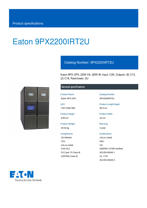
Eaton 9PX2200IRT2UEaton 9PX UPS, 2200 VA, 2200 W, Input: C20, Outputs: (8) C13,(2) C19, Rack/tower, 2UGeneral specificationsEaton 9PX UPS9PX2200IRT2U74317208136060.5 cm8.65 cm44 cm25.02 kg 2 yearCE MarkedTUVcULus ListedCSA 22.2FCC part 15 Class B CISPR22 Class B cULus ListedEACCEENERGY STAR certified IEC/EN 62040-1UL 1778IEC/EN 62040-2Product Name Catalog Number UPC Product Length/Depth Product Height Product Width Product Weight Warranty Compliances CertificationsView runtime graph Hot-swappable internal batteries and extended battery modules (EBMs)612 V / 7 Ah Sealed, lead-acidYes(8) C13, (2) C19Online/Double-conversion 2200 W 2200 VA Sine wave 230V1230V default (200/208/220/230/240V)200/208/220/230/240 V +/- 1%350/60 Hz 1C20 41.8m230V default (200/208/220/230/240V)176-276 V (100-276 V with derating)Runtime graph Battery management Battery replacementBattery quantity Battery rating Battery type Extended battery capability Receptacle TopologyWattage VA rating Output waveform Voltage Output power factor Output nominal voltageOutput voltage rangeVoltage distortion output (linear load) - max Output frequency Feed type Input connection Input cord length Input nominal voltageInput voltage rangeCommunicationABM & Temperature compensated charging method (user selectable)Automatic battery test Deep discharge protection Automatic recognition of external battery units USB port (HID compliant)Serial port (RS232)Mini terminal block for remote On/Off Mini-terminal block for remote power off Mini-terminal block for output relayDry contacts (3 outputs, 150/60 Hz40-70 Hz>.99One slot for optional communication card NoNoEaton Intelligent Power Manager, Eaton Intelligent Power Protector Multilingual graphical LCD display OtherYes3000 m Online: 488<40 dB at 1 meter 0-96% non-condensing 0° to 40°C (32° to 104°F)Nominal frequency Input frequency range Input power factor Expansion slotsEthernet interfaceIncludes network card Software compatibilityUser interfaceType of interface Potential free switch contact Altitude BTU Rating Noise level Relative humidity Temperature range Special featuresinput, optocoupler, DB9)Double conversion topology Constantly monitors power conditions and regulates voltage and frequency First UPS in its class to provide Unity power factor (VA=W)Energy Star qualified, provides the highest efficiency level to reduce energy and cooling costs Internal bypass allows service continuity in case of UPS faultNext-generation graphical LCD displayCompatible with Virtual environments (VMware, Hyper-V, Citrix Xen, Redhat)Meter energy consumption (down to the managed outletRack/tower2U482.6 mm (19 inch) device Yes93.511YesNo Eaton UPS Services Quick Guide 2021 Eaton UPS and battery servicesEaton Bypass Power Module (BPM) user guideEaton Specification Sheet - 9PX2200IRT2UForm factorRack size Construction type Rack mounting kit EfficiencyPackage contentsPhase (input)Phase (output) Internal bypassHot swap powerAuto shutdown function BrochuresManuals and user guides Specifications and datasheetsgroups)Hot swappable batteries Advanced Battery Management (ABM) technology to increase battery lifetimeLong backup time with up to 4 optional EBMUPSInput cable(2) IEC-IEC output cables USB cableSerial cable(2) brackets for 19’ mounting (2) Rack-mounting kit(2) Supports for tower mountingCable locking system Safety instructions Quickstart guideEaton Corporation plc Eaton House30 Pembroke Road Dublin 4, Ireland © 2023 Eaton. All Rights Reserved. Eaton is a registered trademark.All other trademarks areproperty of their respectiveowners./socialmediaYes。
MSI 10th Gen Intel Core i7 系列电脑系统说明说明书

© 2023 Micro-Star Int'l Co.Ltd. MSI is a registered trademark of Micro-Star Int'l Co.Ltd. All rights reserved.Intel, the Intel logo, the Intel Inside logo and Intel Core are trademarks of Intel Corporation or its subsidiaries in the U.S. and/or other countries.SPECIFICATIONSOperating System Windows 10 Home Windows 10 ProFREE Upgrade to Windows 11*CPUUp to 10th Gen Intel ® Core™ i7 Processor System Memory 2 x DDR4 2666MHz U-DIMMs, up to 64GBVGA Up to MSI GeForce® RTX 2070 Super graphics card Sound 7.1 Channel HD Audio with Nahimic audio enhancer (ALC1200-VD1)Storage2x M.2 2280 SSD (1xSATA/PCIe Combo, 1x PCIe)2 x 2.5" HDD / SSD I/O (Front)1x USB 3.2 Gen 1 Type C 1x USB 3.2 Gen 1 Type A 1x USB 2.0 Type A 1x Mic-in1x Headphone-outI/O (Rear)5x Audio jacks1x Optical S/PDIF out 1x RJ45 (2.5 LAN)3x USB 3.2 Gen 1 Type A 1x USB 3.2 Gen 1 Type C 1x DP out (1.2)1x HDMI™ (supports 4K @24Hz as specified in HDMI 1.4b)2x USB 2.0*Tips: The display function is only available on non F series NRealtek RTL 8125B (2.5G)Cooling System Air Cooler Volume10.36 L / 21.89pt Dimension (WxDxH)129.74 x 382.73 x 396.39 mm/ 5.1" x 15.06" x 15.6"Accessories1x Manual (optional)1x Quick guide 1x Warranty card 1x Power cordSoftwareDrivers & MSI Utilities MSI Gaming centerAnti-Virus (60 days trial)technology, delivering speeds up to 2400Mbps.GeForce RTX™ Graphics CardBuilt with MSI GeForce RTX™ Graphics Card, up to 40 percent more performance than previous generation.Silent Storm Cooling 3Exclusive, silent and powerful cooling system that embraces several separated chambers for component cooling.CONNECTIONS1. 1x USB 3.2 Gen 1 Type C 3. 1x USB2.05. 5x Audio jacks / 1x Optical S/PDIF 7. 1x USB 3.2 Gen 1 Type A / 1x USB 3.2 Gen 1 Type C 9. 2x USB 2.0 Type A2. 1x USB3.2 Gen 1 Type A4. 1x Mic-in /1x Headphone-out6. 1x RJ45(2.5G LAN) / 2x USB 3.2Gen 1 Type A 8. 1x DP out (1.2) / 1x HDMI™ out (1.4)G e n e r a t e d 2023-05-10, c h e c k f o r t h e l a t e s t v e r s i o n w w w .m s i .c o m /d a t a s h e e t . T h e i n f o r m a t i o n p r o v i d e d i n t h i s d o c u m e n t i s i n t e n d e d f o r i n f o r m a t i o n a l p u r p o s e s o n l y a n d i s s u b j e c t t o c h a n g e w i t h o u t n o t i c e .。
- 1、下载文档前请自行甄别文档内容的完整性,平台不提供额外的编辑、内容补充、找答案等附加服务。
- 2、"仅部分预览"的文档,不可在线预览部分如存在完整性等问题,可反馈申请退款(可完整预览的文档不适用该条件!)。
- 3、如文档侵犯您的权益,请联系客服反馈,我们会尽快为您处理(人工客服工作时间:9:00-18:30)。
2. Hubble Space Telescope
a space telescope carried into orbit by the Space Shuttle Discovery in April 1990
named after the American astronomer Edwin Hubble
5. American Astronomical Society
a US society of professional astronomers and other interested individuals, headquartered in Washington, DC
The basic objective of the AAS: to promote the advancement of astronomy and closely related branches of science
named after the open star cluster known in English as the Pleiades
the largest telescope in the world to use a single mirror as its primary mirror
4. Gravitational Lensing
one of the largest and most versatile space telescopes, and well-known as both a vital research tool and a public relations boon for astronomy.
the only telescope ever designed to be serviced in space by astronauts
Additional Materials
Index
1 Information 2 Challenge Yourself
Background Information
1. Dark Matter
Learning about dark matter helps determine the shape of the universe.
Its secondary purposes: enhancing astronomy education and providing a political voice for its members through lobbying and grassroots activities
BACK
Four servicing missions: Servicing Mission 1 in December 1993 to correct Hubble’s imaging flaw; Servicing missions 2, 3A, and 3B to repair various sub-systems and replace many of the observing instruments with more modern and capable version
Over the second half of the 20th Century many other important contributions to theories of dark matter have been made by the like of Mordehai Milgrom and Yakov Zel’dovich.
Challenge Yourself
1. What features do spacesuits have?
3. Subaru Telescope
the 8.2 meter flagship telescope of the National Astronomical Observatory of Japan, located at the Mauna Kea Observatory on Hawaii
Fritz Zwicky, a Swiss astrophysicist, was the pioneer in this field and the first to theorize dark matter in 1933, at the California Institute of Technology.
Zwicky observed that there was 400 times the mass in
th1e Coma cluster of galaxies. Through further
observation, he came to the conclusion that there must have been “invisible matter” or “dark matter” holding galaxies together. In 1950, a woman named Vera Rubin made another startling discovery. Her conclusions contradicted Newtonian laws. She built on the theories of Zwicky to discover that galaxies showed an “extra motion.
Light is bent by clumps of matter along its path. Albert Einstein predicted this socalled gravitational lensing when he characterized gravity as the curvature of space-time.