H54RA-80.00M中文资料
高流直挂NAMUR阀门电磁阀系列产品简介说明书
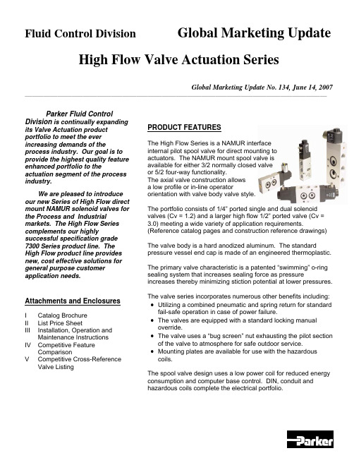
Fluid Control Division Global Marketing Update High Flow Valve Actuation SeriesGlobal Marketing Update No. 134, June 14, 2007 __________________________________________________________________________________________________________________________________ Parker Fluid ControlDivision is continually expanding its Valve Actuation product portfolio to meet the ever increasing demands of the process industry. Our goal is to provide the highest quality feature enhanced portfolio to the actuation segment of the process industry.We are pleased to introduce our new Series of High Flow direct mount NAMUR solenoid valves for the Process and Industrial markets. The High Flow Series complements our highly successful specification grade 7300 Series product line. The High Flow product line provides new, cost effective solutions for general purpose customer application needs.Attachments and EnclosuresI Catalog BrochureII List Price SheetIII Installation, Operation andMaintenanceInstructionsIV Competitive FeatureComparisonV CompetitiveCross-Reference ValveListing PRODUCT FEATURESThe High Flow Series is a NAMUR interfaceinternal pilot spool valve for direct mounting toactuators. The NAMUR mount spool valve isavailable for either 3/2 normally closed valveor 5/2 four-way functionality.The axial valve construction allowsa low profile or in-line operatororientation with valve body valve style.The portfolio consists of 1/4” ported single and dual solenoid valves (Cv = 1.2) and a larger high flow 1/2” ported valve (Cv = 3.0) meeting a wide variety of application requirements. (Reference catalog pages and construction reference drawings)The valve body is a hard anodized aluminum. The standard pressure vessel end cap is made of an engineered thermoplastic.The primary valve characteristic is a patented “swimming” o-ring sealing system that increases sealing force as pressure increases thereby minimizing stiction potential at lower pressures. The valve series incorporates numerous other benefits including: •Utilizing a combined pneumatic and spring return for standard fail-safe operation in case of power failure.•The valves are equipped with a standard locking manual override.•The valve uses a “bug screen” nut exhausting the pilot section of the valve to atmosphere for safe outdoor service.•Mounting plates are available for use with the hazardous coils.The spool valve design uses a low power coil for reduced energy consumption and computer base control. DIN, conduit and hazardous coils complete the electrical portfolio.Global Marketing Update No. 134, June 14, 2007 __________________________________________________________________________________________________________________________________ OPERATION FUNCTIONALITY3/2 Single Solenoid (4 ported, 2 position)NAMUR valve, solenoid operated, for 3-way normally closed operation. In case of an electrical or air failure, valve returns to a fail-safe position through pneumatic and assisted spring return.5/2 Single Solenoid (5 ported, 2 position)NAMUR valve solenoid operated, for 4-way, 2 position operation. In case of an electrical or air failure, valve returns to a fail-safe position through pneumatic and assisted spring return.5/2 Dual Solenoid (5 ported, 2 position)NAMUR valve used for 4-way, 2-position operation. In case of an electrical or air failure, valve “fails as is”. Therefore, valve remains in last position upon failure and will not return to a predetermined position.5/3 Dual Solenoid, Center Position Closed (5 ported, 2 position)NAMUR valve used for 4-way, 2-position operation. In case of an electrical or air failure, the spool returns to the center position thereby removing pressure to the cylinder ports.TECHNICAL PRODUCT CHARACTERISTICSThe new line of valve actuation products offer many features and benefits as follows:Modular construction – Facilitates use of various body configurations and coil options.Mounting Configurations - Direct mount NAMUR pattern with axial operator orientation for single and dual solenoid models for low profile mounting requirements.Manual Override – Standard on all models for manual valve operation during start-up and diagnostic procedures.7mm (1.2Cv ) and 12mm (3.0 Cv) orifice sizes – Multiple sizes to meet various application demands to ensure the solenoid valve is properly sized.Body Materials - Lightweight anodized aluminum.Spool Design – Stainless steel with NBR sealing materials.Exhaust Pilot Cap– Protected pilot sleeve exhaust using “Bug Screen” nut. Helps protect against plugging, dirt, and insects, etc.Ratings – Meets pressures up to 150 psi.Ambient Temperatures – From 14°F (-10°C) to 122°F (50°C), serving most temperature environments. Fluid Temperatures – From 32°F (0°C) to 104°F (40°C).COIL PRODUCT CHARACTERISTICSA selection of low power encapsulated coils as follows:•DIN coil - with 3-pin DIN 43650 type B plug.•Conduit - 3-wire coil.•Hazardous – 3-wire coil with FM and CSA agency approvals meeting Class 1, Groups A,B,C,D and Class II, Groups E,F,G. Meets EEx m II T4 Division 1 requirements.NAMUR INTERFACEMany actuator manufacturers utilize a common mounting pattern referred to as a NAMUR interface for mounting configurations of solenoid valves.The actuator interface dimensions for NAMUR mounting of the pilot valve to the actuator is shown below (dimensions in millimeters).MATERIALS OF CONSTRUCTIONBody: Anodized AluminumEnd Covers: Thermoplastic – Glass-Filled Polyamid 6/6Plunger: 430 Stainless SteelCore Tube: 304 Stainless SteelSteelSprings: StainlessSeals: NBRCages: Polyamide Filled ThermoplasticSteelSpool: StainlessShading Rings: CopperMOUNTING BOLTSThe standard NAMUR interface includes (2) mounting bolts to mount the valve on to the actuator, a positioning stud and two O-rings seals.MOUNTING PLATESDue to the increased width of the hazardous coil to comply with FM and CSA certifications, a mounting plate must be installed as shown in the photograph.The mounting plate kit contains the plate, 2 o-rings, and 2 longer mounting screws.For the ¼” port valve, order kit N60001. For the ½ “ port valve, order kit N60002.ElectricalStandard voltages and voltage code:VOLTAGE CODE 12VDC A 24VDC B 120/60 C 240/60 D 24/60 E 120/50-60 F 240/50-60 GSolenoid Coil SpecificationsThe electrical portfolio is comprised of general purpose class F DIN coil per 43650B and conduit class H coils rated for NEMA classification Types, 1, 2, 3, 3S, 4, 4X. In addition, the hazardous location class H coil is rated for NEMA classification Types 7 and 9; Class I, Divisions 1 and 2, Groups A,B,C,D and Class II, Division 1, Groups E,F,G. The coils are rated for continuous duty application demands.The electrical selector table summarizes each coil specification:Coil Type Coil Part Number Class Protection Construction Agency22mm DINND1x F DIN connector needed for IP65 protection Per DIN 43650B epoxy moldedUL,CSA Conduit –Ordinary locationNC1x H Type 1,2,3,3S,4,4X Epoxy molded, ½ inch NPT conduit None Conduit –Hazardous locationNH1xHType 4X,7,9½ inch NPT conduitCSA,FMCOMPETITIVE FEATURES AND BENEFITSThe primary valve characteristic is a patented “swimming” o-ring sealing system that increases sealing force as pressure increases thereby minimizing stiction potential at lower pressures.The diagram shows a typical cross section view of the valve.valve-head to keep moisture out in brass or in stainless steel available on request, only in combination with alu-head Spool in stainless steel, other inner-parts made from brass, NBR, POM stainless steel Fiber-enforced PA-head, aluminium-version on request 360° turnable,Date CodePRODUCT LABELINGValves are sold in either:• A modular format ordering pressure vessel and coil separately. • Fully assembled with coil assembled to pressure vessel.In either case, the pressure vessel valve body provides the valve identification information defining the valve part number, performance rating and date code. Sample pressure vessel markingCoils will be marked with the appropriate part number, voltage and wattage, and agency information.Sample coil markingAll valves will be packaged with an installation, operation and maintenance instruction sheet indicating conformity with the CE Mark.ORDERING INFORMATIONPRODUCT OFFERINGReference the enclosed catalog brochure (Attachment I) describing the High Flow Series product offering. The catalog pages describe the valve features, general specifications, valve and electrical selection guide, dimensional drawings, and ordering information.PRICINGPressure Vessel list prices for the High Flow NAMUR Series valves are shown in Attachment II. ORDERING INFORMATIONThe Series uses a simple valve number to identify each model. The valves are available fully assembled or in modular form allowing application flexibility in electrical selection. The electrical parts can also be purchased in modular form.Reference the enclosed catalog pages.•When purchasing individual pressure vessels, select the pressure vessel shown on the catalog page and associated list price.•When ordering electrical parts, select the electrical part and associated list price for standard voltages.•When ordering complete valves, add the list price of each component to determine the complete list price for the fully assemble valve selected.The voltage code is the last character of the fully assembled valve or electrical part selected. For example, selecting a single solenoid, 5/2 configuration, 120/60 DIN coil, the complete valve number is:U341N03 + ND1FAVAILABILITY AND DELIVERYParker Fluid Control Division plans to maintain an appropriate service level of finished goods stock to meet business demand of the following NAMUR mount valves. If finished goods stock is available, units will be shipped within 5 business days from receipt of order for order quantities of 25 units or fewer:Product Class 1 Items:U331N03U341N03ND1B, ND1F, ND1G - 24vdc, 120vac, 240vacNC1B, NC1F, NC1G - 24vdc, 120vac, 240vacNH1B, NH1F, NH1G - 24vdc, 120vac, 240vacProduct Class 4 Items - the estimated lead-time (subject to change) is 4 weeks from receipt of order.U347N03U342N03U331N04U341N04ND1A - 12vdcNC1A - 12vdcNH1A - 12vdcAs always, for larger customer orders requiring shorter lead-times, Parker Fluid Control Division will work jointly with each customer by establishing finished goods items to meet customer provided forecasts.DISCOUNTSParker Fluid Control Division’s standard published discounts apply. Current terms and conditions apply for the product.SERVICERETURNSParker Fluid Control Division’s standard return policy applies.REPAIR PARTSParker Fluid Control Division is NOT offering component repair kits for field service at this time. Since the valve is a small, cost effective product, industry experience shows the process markets will replace the complete valve rather than rebuild the valve in the field.INSTALLATION OPERATION AND MAINTENANCE (IOM)An IOM has been created describing valve operation, installation and mounting instructions, maintenance, and troubleshooting procedures for the high flow Series NAMUR valves. Reference Attachment III, IOM HN01.WARRANTYParker Skinner’s standard 2 year warranty policy applies to the pressure vessel, coil and enclosures.PROMOTIONPromotional materials have been prepared to expedite introduction into the market place.CATALOG / LITERATURE• A new catalog has been created containing the features, specifications and outline drawings of the high flow Series valves.• A product launch announcement containing product introduction materials and detailed competitor information will be distributed to each Territory Sales Manager.TRAINING•Each Territory Sales Manager should contact their respective Fluid Control Division Authorized Distributor and Valve Actuation Accounts to arrange training.•The new high flow Series valves will be included in Fluid Control Division’s Valve Actuation Training Program.•Samples of the new high flow Series actuation valves will be provided upon receipt with a complete sample request form following standard Skinner Valve ™ sample procedures.PHASE-OUT OF 2340, 3300 and 7341 Series Product LinesThe introduction of the new product line has resulted in significant product overlap with the 2340, 3300 and 7341 series valves. Therefore, we are taking the following actions to phase out these product lines. Due to the low volume of many of the products, the old families will be replaced by the new High Flow NAMUR valve as follows:The Phase In – Phase Out schedule will begin upon introduction of the new High Flow NAMUR valve. It may be possible to order a specific older model until current inventory is fully depleted at which time the old product will no longer be available. Parker reserves the right to discontinue the old products sooner if conditions warrant.COMPETITIVE REVIEWReference Competitive Feature Comparison of select valves in Attachment IV. The attachment contains a broad selection of valves representative of the competitive offering.Attachment V provides a competitive cross-reference part number listing based on available information for the individual competitors.ASCO is considered the market leader for actuation valves. Other primary competitors include Versa, Automatic, and Herion.Below is a general description of the competitive product offerings.ASCOThe ASCO 8551 Series offers a product line of NAMUR and pipe mount versions. The portfolio consists of pad mount valves with various operator configurations with single and dual solenoids.In general, the ASCO 8551 Series consists of:•Anodized aluminum and stainless steel body using resilient spool construction. •Convertible 3-way and 4-way models based on the newer version. The older version consists of non-convertible 3-way and 4-way models that are similar to the 7300 Series. •20/35 to 150 psi operating pressure differential.•Single and dual solenoid, vertical and axial operator models available.•Cv 0.50 to 0.86.•AC versions from 2.5 watts to 10.1 watts.DC versions from 3.0 watts to 11.6 watts.•DIN, watertight and explosion solenoids available based on model.The Parker High Flow Series NAMUR mount valves are specified to meet the application requirement. A conversion or mounting plate is not required when using a DIN coil. The valve mounts directly to the actuator in a very cost-effective and efficient manner.VersaVersa offers a series of valves for process control markets including applications for pneumatic actuators and 316 stainless valves for corrosive requirements. The valve offering consists of NAMUR, body ported, lockout valves, latching and manual reset valves and redundant solenoid valves.Specific to the actuation area, Versa offers a convertible 3-way / 4-way version and direct acting 3-way pad mount valve. Available options include Intrinsically Safe, Low power and CENELEC flameproof enclosures.•3/2, 5/2 port plug versions. Valves field convertible by relocating a port plug converting from 3-way to 4-way or 4-way to 3-way.•Anodized aluminum, stainless steel and brass body using resilient spool construction. •Single and dual solenoid models (5/2) and dual solenoid centered position (5/3) with standard manual override.•15 to 115 psi operating pressure, Cv 0.75.•DIN, conduit and explosion solenoids available based on model.•8.5 watt AC, 10.5 watt DC.•Class A or F insulation.Automatic Valve Co. (AVC)They are considered the low price player in the market. They offer a NAMUR mount COMPACT Series. The series has limited options, but offers the ability to order valves with the solenoid on the left or right side.•3/2, 5/2 port plug versions, 1/4” npt porting only.•Anodized aluminum body using resilient spool construction.•40 to 150 psi operating pressure differential, Cv 1.0.•NEMA 4 and 7 solenoids, remote air and manual operators.•DIN, conduit and explosion solenoids available based on model, coil ratings to Class H. Herion•3/2, 5/2 port plug versions, NAMUR mount, 1/8” NPT, ¼” NPT, ½” NPT.•Anodized aluminum body using resilient spool construction.•25 to 150 psi operating pressure differential, Cv 1.1 to 1.4.•NEMA 4 and 7 solenoids, manual operators.•Low power coils available at reduced ratings.•DIN, conduit and explosion solenoids available based on models.•Locking and momentary manual override available.•Requires spacer plate for hazardous coil.Max-Air TechnologyU.S. division of M Technology Srl located in Italy. Also offer rack & pinion actuators and position indicators and mechanical switches that can be assembled as a complete unit.•3/2, 5/2 port plug versions, 1/4” npt porting only.•Epoxy coated aluminum body with plated spool. And standard manual override.•DIN and explosion solenoids available based on model, Class F standard, Class H optional. •Uses a pop-up air indicator located in pilot section to indicate if the solenoid valve is pressurized.•Optional IS and ATEX DIN coil construction.Q&A SESSIONQ? Why did we introduce the High Flow NAMUR Series valve product line?The principle reason for introducing the valve line is to meet increasing market demands for smaller, cost effective valve models for the process valve actuation markets. The Parker 7300 Series valve line offers a high-end specification grade product in multiple bodymaterials to meet general purpose ordinary requirements to the most stringent application requirements. Also, the 2340 series of aluminum body valves lacked a suitable hazardous coil limiting application potentials.The new product line overcomes the 2340 series deficiencies at a most competitive price for general purpose application requirements. The portfolio includes expanded models with higher flow factors for larger actuator designs. The new line includes a 1/2” namur valve to accommodate the trend toward larger actuators and higher flows.Finally, we’re continuing our strategic thrust in the process markets with a new product offering and responding to competitive product positions.Q? Will the High Flow Series product line replace the 2340 Series and 3300 Series valves?In a word, yes. First, since the introduction of the 2340 series and 3300 series valves(dating back to the late ‘90’s), many changes have taken place in the market. The general purpose ordinary location market generally does not require the high technical or safety standards found in these product lines. Due to deficiencies in the former product lines, specifically the lack of a hazardous coil, we were not able to meet the availability and price competitiveness. The current product lines are focused toward higher technicalrequirements resulting in low-volume market segments and overlap price-wise with the 7300 Series valve lines. To reduce complexity and offer a simplified, cost-effective processactuation valve line, the 2340 catalog portfolio will (eventually) be phased-out.Q? Describe the comparison to the 7300 product line.The High Flow Series offers similar product features and benefits compared to the 7300 Series, in particular:• Total modularity.•Interchangeable electrical parts.•Unique spool designs to eliminate risk of sticking.•High quality in proven valve designs.•Standard manual override.The distinctive features of the High Flow Series compared to the 7300 Series include:• Smaller physical size.•More cost effective compared to 7300 with manual override (for certain type application needs).Q? Where must the 7300 series valves be used versus the new line?The 7300 series contains features, multiple operator configurations and electrical coilsappropriate for more demanding critical applications including:•Higher flows appropriate for higher actuator torque specifications.•Intrinsically Safe (IS) and ultra low power environmental conditions.•Manual reset options used as a safety device on solenoid valves to prevent process resumption without manually resetting each valve.•Low temperatures application demands of –40°F/C.•Field convertible manual overrides including locking and momentary requirements. Q? Will a conversion plate eventually become available?The product line contains individual 3-way and 4-way valve configuration. When utilizing a DIN coil, this method provides the most cost-effective, competitive solution. Granted, whilea conversion plate offers the benefit of using one style valve, it also adds significant andunnecessary costs. Since the valve is focused and priced to pursue higher volumerequirements, the valve functionality will be known.。
迪拜科技 迪拜智能家居系统 型号:DJ-H100说明书
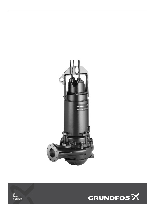
说明书GRUNDFOSS pumps, ranges 50-70S1, S2, S3, ST, SV7.5 - 155 kW安装和使用说明书中文 (CN)2中文 (CN) 安装和使用说明书中文版本。
目录页1. 本文献中所用符号2. 概述该手册对配备功率为7.5至160 kW电机、50-70系列的格兰富S潜水式污水及废水泵的安装、操作及保养进行了说明。
本手册还对防爆泵作了特别说明。
2.1 应用50-70系列的S泵适用于公共设施、私人住宅以及工业应用中的污水及废水泵送设计。
水泵具有多种安装方式,包括潜水式、干式、卧式以及立式安装。
最大颗粒尺寸: 80-145 mm,视具体性能范围而定。
2.1.1 潜在爆炸性环境在潜在爆炸性环境中应使用50-70机型的S防爆泵。
见章节 2.5.1防爆证书和防爆等级。
1.本文献中所用符号22.概述22.1应用22.2运行条件32.3声压级32.4型号说明42.5铭牌53.安全63.1潜水及干式立式安装的起吊点(S/C/D)64.运输与存放65.安装75.1安装类型75.2在自动耦合装置上的潜水安装85.3干式安装85.4潜水式安装,便携式95.5圆筒管内立式安装95.6泵的控制装置95.7电流分离95.8IO 11395.9热敏开关95.10湿度开关95.11热敏电阻105.12Pt100温度传感器106.WIO 传感器 (油中含水率传感器)106.1WIO 传感器为水泵配件106.2装配WIO 传感器106.3电气数据,WIO 传感器106.4传感器信号107.电气连接117.1变频器操作117.2电缆数据118.启动128.1检查旋转的方向129.保养和服务139.1检查油位并更换机油139.2检查并调整叶轮间隙149.3防爆型S 泵,50-70系列159.4受污染的泵1510.故障查找1611.回收处理16警告装机前,先仔细阅读本安装操作手册。
安装和运行必须遵守当地规章制度并符合公认的良好操作习惯。
瑞丰WI -E-045 A1 产品说明书

applications which has special requirement in quality and reliability. 如产品需要用在有特殊质量要求及可靠性要求的地方,请提前咨询瑞丰的销售人员以取得相关信息。
4. Without Refond permission, customer shouldn’t disassemble and analyze the LEDs. If the customer find invalid product, please notice Refond in written form.在取得瑞丰的同意前,客户不应该对产品进行拆解分析,如发现失效产品,请直接书面通知瑞丰。
Features 特征Extremely wide viewing angle.发光角度大Suitable for all SMT assembly and solder process.适用于所有的SMT 组装和焊接工艺 Moisture sensitivity level: Level 3.防潮等级 Level 3Package:4000pcs/reel.包装每卷4000pcsRoHS compliant. 满足RoHS 要求Description 描述The Colour LED which was fabricated by using a yellow chip 该产品为黄光LED ,是由黄光芯片封装形成Applications 应用Optical indicator.光学指示Switch and Symbol,Display.开关和标识、显示器等General use.其他应用Package Dimension 外观尺寸NOTES:1.All dimensions units are millimeters. (所有尺寸标注单位为毫米)2.All dimensions tolerances are ±0.2mm unless otherwise noted. (除特别标注外,所有尺寸公差为±0.2毫米)Electrical / Optical Characteristics at Ts=25°C 电性与光学特性Absolute Maximum Ratings at Ts=25°C绝对最大值Typical optical characteristics curves典型光学特性曲线°C)Packaging Specifications 包装规格⏹Tape Dimensions 载带尺寸⏹Note:The tolerances unless mentioned ±0.1mm. Unit : mm 注:未注公差为±0.1毫米,尺寸单位:毫米。
最终EH4使用说明书
美国劳雷工业有限公司
目录
0.0 简介......................................................................................................................................................2 1.0 系统配件 ............................................................................................................................................. 3
EMI ElectroMagnetic Instruments, Inc.
STRATAGEM
26716-01 REV. F
EH-4使用说明书
版本2.19
版权©2007
GEOMETRICS, NC.
2190 Fortune Drive, San Jose, CA 95131, USA Phone: (408) 954-0522 Fax: (408) 954-0902
标准接收机配件..................................................................................................................................... 3 可选接收机组件 .................................................................................................
电磁流量计(上海光华)
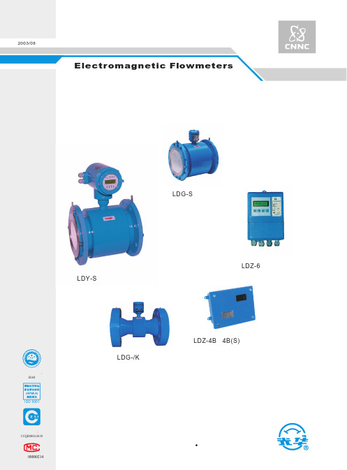
应用 连接法兰
产品标准 安装形式
* 选择件
LDG-S电磁流量传感器
DN10~1200 1Cr18Ni9Ti 0Cr18Ni12Mo2Ti Ti Ta Hb Hc 等 聚四氟乙烯、氯丁橡胶、 聚氨酯橡胶 导电性液体(含固液二相) > 20μS/cm 0.5、1.0 0.5m/s~10m/s -25℃~+ 150℃(橡胶衬里 ≤ 80℃)
(聚氨酯衬里 ≤ 45℃) 4.0MPa~0.6MPa(按口径分) ≤0.5A 配 LDZ - 4B、4B (S) 型 ≤ 0.25A 配 LDZ - 5 型、 LDZ - 6 型 标准型 IP65(防喷水) 特殊型 IP67(防浸水)
IP68(潜水) LDZ-4B、4B(S)型 LDZ-5型 、LDZ-6型 0~10mA DC 或 4~20mA DC 1~5000Hz(配LDZ-6型)
工作压力 工作电流 防护等级
最大潜水深度 5m ≤0.5A或≤0.25A IP68(防潜水)
配套 转换器型号 输出信号
显示 通讯接口 适用电源
应用
LDZ-4B、4B(S)型 LDZ-5型 、LDZ-6型 0~10mA DC或4~20mA DC
* * 频率 (脉冲) 上限1-5000Hz (上限5000CP/S)
ISO 9001
注册证号: CCQE0800A0130
沪制00000214
LDG-/K 传感器
LDZ-4B、4B(S)型 转 换 器
中国 核工 业集团公司 上海光华 仪表 厂
目 录
1.概述 ..................................................................................................................................................................1 2.工作原理...........................................................................................................................................................1 3.性能简介...........................................................................................................................................................2 4.外形和安装尺寸................................................................................................................................................5 5.电磁流量计口径的选择.....................................................................................................................................8 6.电极材料的选择..............................................................................................................................................10 7.衬里材料的选择..............................................................................................................................................11 8.防护等级的选择..............................................................................................................................................11 9.接地环的选择..................................................................................................................................................11 10.传感器在管道上的安装..................................................................................................................................11 11. 选型编码说明................................................................................................................................................16 12.电磁流量转换器............................................................................................................................................18 13.防爆合格证...................................................................................................................................................22
派克液压中文样本

液压注意 – 用户方责任 错误或不当地选择或使用本样本或有关资料阐述的产品,可能会导致人生伤亡及财产损失! 本样本以及其它由派克汉尼汾公司及其子公司、销售公司与授权分销商所提供的资料,仅供用户专业技术人员在对产品和系统的选型进行深入调查考证时参考。
用户应全面分析自身设备的运行工况、适用的工业标准,并仔细查阅现行的样本,以详细地了解产品及系统的相关信息,通过自己的分析和试验,对产品及系统的独立的最终选择负责,确保能满足自身设备的所有性能、耐用性、维修型、安全性以及预警功能等要求。
对于派克或其子公司或授权分销商而言,应负责按用户提供的技术资料和规范,选择和提供适当的元件或系统,而用户则应负责确定这些技术资料和规范对其设备的所有运行工况和能合理预见的使用工况是否充分和准确。
目录目录页次概述 1 订货代号 2 技术参数 4 变量控制器 5 控制选项 “C”, 压力限定(恒压)变量控制器 5 控制选项 “L”, 负载传感及压力限定变量控制器 6 控制选项 “AM”, 带遥控口的标准型先导式压力限定变量控制器 7 控制选项 “AN”, 带ISO 4401 NG06先导阀安装界面的先导式压力限定变量控制器 8 控制选项 “AE”及“AF”, 带电磁比例调节的先导式压力限定变量控制器 9 控制选项 “AMT”, “ALT”及“LOT”, 带最高压力限定的扭矩限定(恒功率)变量控制器 10 P1性能特性 11典型流量特性 11 典型总效率特性 13 典型轴输入功率特性 15 典型噪声特性 18 典型轴承寿命 20 PD性能特性 22典型流量特性 22 典型总效率特性 24 典型轴输入功率特性 26 典型噪声特性 29 典型轴承寿命 31 安装尺寸 33 P1/PD 018 33 P1/PD 028 36 P1/PD 045 40 P1/PD 060 44 P1/PD 075 49 P1/PD 100 54 P1/PD 140 59 变量控制器安装尺寸 65 可提供的扩展的液压产品 75派克汉尼汾备记派克汉尼汾概述简介, 优点派克汉尼汾简介 • 开式回路用轴向柱塞式变量液压泵 • 中压,连续工作压力280 bar • 高驱动转速型,适用于行走机械; 低噪声型,适用于工业应用 • 静音及高效的控制效能 优点 • 总结构尺寸紧凑 • 低噪声• 流量脉动小,进一步降低噪声• 采用弹性密封,不使用密封垫,从而避免外泄漏的产生• 总效率高,功耗小,减小发热• 采用带无泄漏调节装的简单变量控制器 • 符合SAE 及ISO 标准的安装法兰及油口 • 采用圆锥滚柱轴承,使用寿命长 • 全功率后驱动能力• 后部或侧面油口配置可选• 泄油口的配置对水平安装及驱动轴向上垂直安装均适用• 带有最大及最小排量调节选项 • 具有壳体至吸口单向阀选项,可延长轴封寿命 • 使用、维修方便 脉动容腔技术下列图表所示为侧向油口配置P1/PD 18, 28及45泵采用 “脉动容腔” 技术的效果,脉动容腔可降低泵出口处的压力脉动幅值40-60%,这样,无需增加成本来加装噪声缓冲元件,便可大大降低液压系统的整体噪声,P1系列 PD 系列出口压力p / bar平均压力脉动 / b a rP1 045出口压力脉动2600 rpm 无脉动容腔2600 rpm 带脉动容腔订货代号18 ml, 28 ml, 45ml派克汉尼汾P 类型 01 驱动轴 转向R 5密封材料E 油口配置0 壳体-吸口 单向阀 0 排量调节 018 排量 S 安装法兰 及油口 S 轴封 M 应用范围A 设计系列0 通轴驱动选项 C0控制选项0附加控制选项 00油漆 00修改代号系列 P D * 仅适用于045排量, “S”型安装法兰及油口00 标准型, 无修改M2 按要求修改 代号修改代号 * 适用于028及045排量 ** 仅适用于045排量 代号设计系列 A 现行设计系列5 氟碳橡胶 (FPM) 代号密封材料 A 82-2 SAE A M33x2 M27x2 BSPP 1/4”, 3/8” 101-2 SAE B M42x2 M27x2 BSPP 1/4”, 1/2” 101-2SAE B M48x2M33x2Ø38/25DN51/25BSPP 1/4”, 1/2”B ISO M33x2 M27x2 BSPP 1/4”,3/8”ISO M42x2 M27x2 BSPP 1/4”, 1/2” ISO M48x2M33x2Ø38/25DN51/25BSPP 1/4”, 1/2”代号 018排量 028排量 045排量 安装法兰及油口 安装 法兰 螺纹 油口 辅助 油口 安装 法兰 螺纹 油口 辅助 油口 安装法兰螺纹油口法兰 油口辅助 油口 S 82-2 SAE A SAE 16/12 SAE 4/6 101-2 SAE B SAE 20/12 SAE 4/8 101-2SAE B SAE 24/16Ø38/2561系列SAE 4/10M ISO M33x2 M27x2 M12x1.5 M16x1.5 ISO M42x2 M27x2 M12x1.5 M22x1.5 ISO M48x2M33x2Ø38/25DN51/25M12x1.5M22x1.5代号 018驱动轴 028驱动轴 045驱动轴 01 SAE A 11T 花键SAE B-B 15T 花键 SAE B-B 15T 花键02 SAE 19-1平键Ø0.75” SAE B-B 平键Ø1” SAE B-B 平键Ø1” 08— SAE B 13T 花键 SAE B 13T 花键 04 ISO/DIN 平键, Ø20ISO/DIN 平键, Ø25ISO/DIN 平键, Ø25 06 SAE A 9T 花键— — PD 工业液压用 代号 系列P1 行走机械用 代号 排量 018 18 ml/rev (1.10 in 3/rev) 028 28 ml/rev (1.71 in 3/rev) 045 45 ml/rev (2.75 in 3/rev) 代号 类型 P 开式回路用变量柱塞泵 U*通用 代号应用范围 S 工业液压 (PD) M 行走机械 (P1) R 顺时针 (右转)L 逆时针 (左转)代号 转向 代号 轴封 S 单唇轴封 * 并不具有控制功能,仅在运输时予以防护,详情见第7页的控制说明。
凝汽式汽轮机

使用说明书产品名称:凝汽式汽轮机产品代号:HS产品型号:NH25/04目录2、汽轮机转速、功率........................................................ 错误!未定义书签。
3、蒸汽参数 (3)4、启动升速曲线 (3)5、公共工程消耗指标 (4)6、汽轮机外形尺寸及重量 (4)9、汽轮机油 (5)三、汽轮机本体及辅机 (6)1、概述 (6)2、纵剖面图 (7)3、汽缸 (7)4、喷嘴组和转向导叶环 (7)5、隔板 (8)6、汽封 (8)7、转子 (9)8、前支座 (10)9、推力轴承前轴承 (11)10、径向轴承 (11)11、后支座 (12)13、盘车装置 (13)14、调阀总成 (15)15、速关阀 (17)16、危急遮断器 (19)17、危急遮断油门 (20)18、错油门油动机 (20)19、速关组合装置 (23)20、蓄能器 (28)21、凝汽器 (28)22、疏水膨胀箱 (33)23、抽气器 (34)24、排汽安全阀 (35)25、转速监测 (37)26、振动监测 (37)27、轴位移监测 (38)28、温度监测 (38)29、505调速器 (39)五、汽轮机管道系统 (41)1、蒸汽管道 (41)2、油管道 (42)3、汽封、疏水管路 (44)七、起动和运行 (44)1、起动前准备 (44)2、起动 (45)3、停机 (46)4、起动、运行、停机的其余要求 (46)5、汽轮机常见故障 (46)九、维护和保养 (49)1、运行时的保养工作 (49)2、停机保养 (49)3、蒸汽系统清洗指南 (51)4、加油和油管理 (53)2、汽轮机转速、功率设计功率kW转速r/min3、蒸汽参数3.1、蒸汽压力以下压力指汽轮机主汽门前的压力,均为绝对压力。
主蒸汽MPa(a)排汽MPa(a)报警和跳闸的设定点参见最终工程资料中KG221-HS -5联锁报警停机图。
SRV05-4中文资料

2
1.90
0.074
3
0.95
0.037
4
2.40
0.094
5
1.00
0.039
K L
G C
MOUNTING PAD
0° - 8°
J
B
M
4
3 2
1 5
PACKAGE DIMENSIONS
DIM
A B C D E F G J K L M
MILLIMETERS
MIN
MAX
2.80 1.50 0.90 0.35 0.85 1.70 0.90 0.09 2.60 0.20 TYP 0.35
PIN CONFIGURATION
I/O 1 1 GND 2 I/O 2 3
6 I/O 4 5 REF 4 I/O 3
05150.R8 5/07
1
SRV05-4
DEVICE CHARACTERISTICS
MAXIMUM RATINGS @ 25°C Unless Otherwise Specified
VF
0.5 Min. to 1.2 Max.
IPP
43
UNITS Watts
°C °C Volts Amps
PART NUMBER
ELECTRICAL CHARACTERISTICS PER LINE @ 25°C Unless Otherwise Specified
DEVICE MARKING
RATED STAND-OFF VOLTAGE (See Note 1)
3.05 1.75 1.30 0.50 1.05 2.10 1.45 0.20 3.00 0.20 TYP 0.55
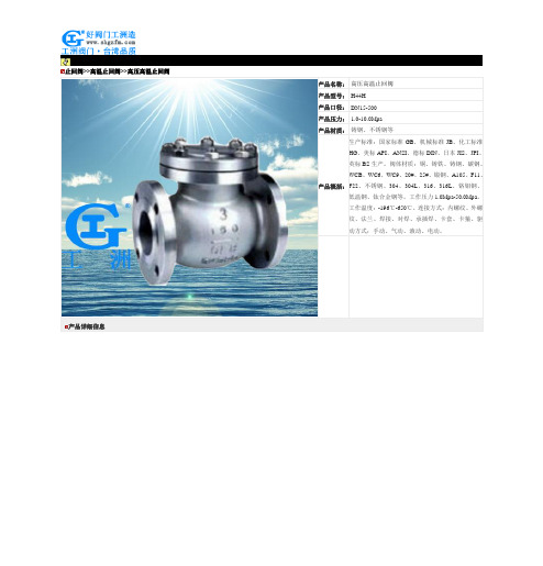
高压高温止回阀-H44H高压高温止回阀
50
285
285
285
285
285
65
382.5
382.5
390
420
420
80
480
480
495
510
510
100
600
637.5
660
630
675
125
855
900
930
900
975
150
1080
1155
1170
1170
1275
200
1650
1725
1875
1725
1875
250
2550
14700
24900
16”
12450
645
682.5
780
825
825
1425
1500
125
855
930
900
975
1125
1200
1200
2025
2175
150
1080
1155
1170
1245
1620
1695
1725
2775
2925
200
1800
1950
1920
2025
2475
2625
2775
4725
4950
250
3150
3375
3525
6750
9600
9900
400
6900
7200
7650
7950
8700
11250
11850
450
8700
特瑞堡中文泛塞密封

2
特康® 泛塞®
■ 概述
特康® 泛塞® 是一种单作用,弹簧施力的密封件,用于 动态和静态运动。
泛塞® 在广泛的应用中是十分有效的。适用于要求具有 较好的耐化学介质的性能时,或者要求密封件工作在 极端温度下,以及用于需要良好的挤压和压缩性能的 场合。
最新资料请访问 2008年5月版
1
特康® 泛塞®
■ 选择正确的密封件
特康® 泛塞® 在所有工业领域的诸如液压缸和气缸之类 的元件设计中提供非常重要的作用,包括: - 极好的密封性能 - 非常耐磨损 - 抗间隙挤出性好 - 良好的耐腐蚀和耐磨性能 - 非常好的温度性能 - 摩擦系数小 - 结构紧凑 - 安装简单 特康® 泛塞® 有各种几何形状和结构,允许针对每种用 途选择最佳的形状。它们能够由各种特康® 材料(我们 的专利PTFE基复合物)制成,这些复合物是专门针对 密封件的配方,并且提供上乘的特性,专门满足我们 客户的要求。 当需要时,也能够用佐康® 材料(我们的专利聚乙烯基 复合物)制成。 为了针对您的用途,选择最好的特康® 泛塞® ,您必须 首先确定功能参数,第4页的表I和表II,以及第5页的 表III则能够用来对密封件和材料进行初选。这些表中详 细给出了在样本的何处能够找到进一步的细节。 考虑配合面的质量也是重要的,它对密封系统的使用 寿命和功能有重大的影响,有关这方面的指南在13页 和14页给出。 如果就有关密封件的技术规格需要帮助,请联系特瑞 堡密封系统公司,可以找您当地的市场部门,或登陆
下面列出泛塞在高达15ms49英尺s的速度下能够密封能够承受200mpa2000bar29000psi以上的高压能够安装在符合milg5514f和din3771的沟槽中弹簧力系统压力varisealvariseal选择表动态mpabapsi静态mpabapsim215454506527606008702709426050015m2s1645450652760600870270942605001005t40202002900606008702709423044615404005801808001160312018426050001t05hf28404005801808001160320032826050001t05roto2815150217525250362510014826050010c满足表ii外套材料选择指南turcont05turcont24turcont24turcont40turcont40turcont01zurconz80turcont78turcont01turcont01最新资料请访问wwwtsstrelleborgcom2008年5月版密封件接触的介质或工作条件静态或稍微动态往复旋转技术数据用途材料型式页码最高压力用途的类型工作温度最高速度标准材料空气气体水蒸气油原油普通化学品石油化学品食品药品真空材料选择指南t012500mm2500mm2500mm2500mm2500mm2500mm2500mm2500mm特殊材料适合较高的辐射负载有关这方面的进一步详细资料请联系特瑞堡密封系统公司
中文四版-SMC样本
2.5, 4
CAT.C06-02A
6, 10, 15
CAT.C06-02A
6, 10, 16
CAT.C04-01A
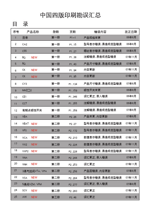
错误内容 产品规格变更
改正日期 06年8月
型号表示错误,易造成选型错误 06年8月
螺纹表示错误,易造成选型错误 06年8月
注解错误,易造成选型错误
07年11月
产品尺寸错误,易造成选型错误 07年8月
内容更新
07年11月
内容更新
07年11月
产品尺寸错误,易造成选型错误 磁性开关变更 词汇更正、录入错误
CAT.ES20-152B CAT.ES20-177A CAT.E256A CAT.ES20-179B CAT.E216B CAT.ES20-95B CAT.ES20-157B P-1991-6 CAT.ES20-160A CAT.E204A CAT.ES20-159A CAT.ES20-159A CAT.ES20-159A CAT.ES20-147A
9
f
B1
h+
□C
ZZ + + 行程
□B
A KF N H
S + 行程 ZZ + 行程
N M
(mm)
缸径 行程范围 (mm)
A AL □B B1 □C D E F G H1
J
(mm) 无防护套 带防护套
无防护套
带防护套
K KA M MM N P S
H ZZ e f h
海德福斯 电比例阀(中文)
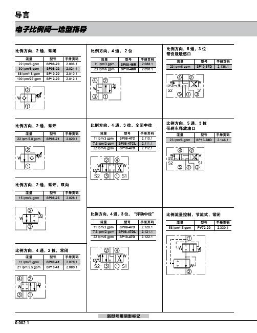
型号 PV08-31 PV70-31 PV72-31 PV76-31
手册页码 2.380.1 2.382.1 2.384.1 2.386.1
比例流量控制,常开
流量 38 lpm/10 gpm 87 lpm/23 gpm
型号 PV70-35 PV72-35
手册页码 2.432.1 2.434.1
比例流量控制,旁通,常闭
流量 22 lpm/6 gpm 30 lpm/8 gpm 64 lpm/17 gpm 151 lpm/40 gpm
型号 PV08-30 PV70-30 PV72-30 PV76-30A
手册页码 2.370.1 2.372.1 2.374.1 2.376.1
比例流量控制,旁通,常闭
流量
型号
手册页码
190 lpm/50 gpm PV42-M30 2.378.1
缩写符号:
比例压力控制,先导溢流,电流增 大压力增大
流量 95 lpm/25 gpm 189 lpm/50 gpm
型号 TS10-26 TS12-26
手册页码 2.852.1 2.854.1
0.002.3
截止阀 (典型)
电子比例阀—选型指导
比例压力控制,先导溢流,电流增 大压力减小
流量 19 lpm/5 gpm 76 lpm/20 gpm 189 lpm/50 gpm
—
推荐的电子控制器
仅指 PCB 板
铁盒式
零件编号 手册页码 零件编号 手册页码
4000046 4000141 4000143 4000144
3.426.1 3.427.1 3.428.1 3.429.1
4000049 4000124 4000130 4000133
H5CR繁体使用说明书
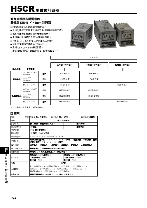
耐電壓
脈衝電壓
耐雜訊 抗靜電 振動
衝擊
壽命 重量 取得規格
持久性 誤動作 持久性 誤動作 機械性 電氣性
AC 2,000V 50/60Hz 1min(在導電端子及露出的非充電金屬之間) 但是,AC24V、DC12 ~ 24V 型為 AC 1,000V 3kV(在電源端子之間)但是 AC24V、DC12 ~ 24V 型為 1kV 4.5Kv(在導電端子及露出的非充電金屬之間) 但是 AC24V、DC12 ~ 24V 型為 1.5kV 藉由雜訊模擬器產生的方形波雜訊(脈波寬度 100ns/1µs 升至 1ns) ±2kV(電源端子之間)(然而DC12~24V型為±480V)、±600V(在輸入端子之間) 8kV(錯誤動作)15kV(破壞) 10 ~ 55Hz 單振幅 0.75mm 3 軸各方向 10 ~ 55Hz 單振幅 0.5mm 3 軸各方向 300m/s2{約 30G} 3 軸各方向 100m/s2{約 10G} 3 軸各方向 1000 萬次以上 10 萬次以上(AC250V 5A 電阻負載) H5CR-L 型約 105g、H5CR-B 型約 160g、H5CR-S 型約 120g 詳情請查閱安全規格認定機種一覽表(2130 ~ 2155 頁)
淺灰色(表色系 5Y7/1)
性能
動作時間的偏差
設定誤差 (包括受到溫度及電壓的影響)
±0.01% ±0.05s 以下(電源起動時)* ±0.005% ±0.03s 以下(信號起動時)**(相對於設定值的比例)
電氣的壽命曲線(參考值)
絕緣電阻
100M Ω 以上(以 DC500VM) 在導電處端子及露出的非充電金屬之間、以及非連續接點之間
• AC100~240V 50/60Hz DC12~240V
RA4系列迷你阀门产品说明书
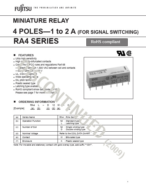
n FEATURESlUltra high sensitivity l High reliability-bifurcated contacts l Conforms to FCC rules and regulations Part 68—Dielectric strength 1,500 VAC between coil and contacts —Surge strength 1,500 V l UL, CSA recognized l Wide operating range l DIL pitch terminals l Plastic sealed type l Latching type available l RoHS compliant since date code: 0418HPlease see page 7 for more information(a) Series Name RA4 : RA4 Series(b) Operation Function Nil : Standard type L : Latching type(c) Number of Coil Nil : Single winding typeD : Double winding type (d) Nominal Voltage Refer to the COIL DATA CHART(e) Contact W : Bifurcated type (f)EnclosureK : Plastic sealed typeNote: F or movable and stationary contact with gold overlay type, add suffix ““-OH””.n ORDERING INFORMATIONRA4 L – D 12 W – K[Example](a) (b) (c) (d) (e) (f)D IS C O NT IN UE D(2009)Nominal Coil resistance Must operate Must releaseNominal MODELvoltage (±10%) voltage*1voltage*1 power RA4-1.5 W-K 1.5 VDC 11Ω +1.0 VDC +0.15 VDC 200 mW RA4- 3 W-K 3 VDC 45Ω +2.1 VDC +0.3 VDC 200 mW RA4-4.5 W-K 4.5 VDC 100Ω +3.1 VDC +0.45 VDC 200 mW RA4- 5 W-K 5 VDC 125Ω +3.5 VDC +0.5 VDC 200 mW RA4- 6 W-K 6 VDC180Ω +4.2 VDC +0.6 VDC 200 mW RA4- 9 W-K9 VDC 405Ω +6.3 VDC +0.9 VDC 200 mW RA4- 12 W-K 12 VDC 720Ω +8.4 VDC +1.2 VDC 200 mW RA4- 18 W-K 18 VDC 1,620Ω +12.6 VDC +1.8 VDC 200 mWRA4- 24 W-K24 VDC2,880Ω+16.8 VDC +2.4 VDC 200 mW RA4- 48 W-K 48 VDC 11,520Ω +33.6 VDC+4.8 VDC200 mWn COIL DATA CHARTS t a n d a r d T y p eNote: *1 Specified values are subject to pulse wave voltage.All values in the table are measured at 20°C.D IS C O NT I NU ED (2009)Nominal Coil resistance Set Reset Nominal MODELvoltage (±10%) voltage*1 voltage*1 power RA4L-1.5 W-K 1.5 VDC 25Ω +1.0 VDC –1.0 VDC 90 mWRA4L- 3 W-K3 VDC 100Ω +2.1 VDC –2.1 VDC 90 mW RA4L-4.5 W-K 4.5 VDC 225Ω +3.1 VDC –3.1 VDC 90 mW RA4L- 5 W-K 5 VDC 278Ω +3.5 VDC –3.5 VDC 90 mW RA4L- 6 W-K 6 VDC 400Ω +4.2 VDC –4.2 VDC 90 mW RA4L- 9 W-K 9 VDC900Ω +6.3 VDC –6.3 VDC 90 mW RA4L- 12 W-K 12 VDC 1,600Ω +8.4 VDC –8.4 VDC 90 mW RA4L- 18 W-K 18 VDC 3,600Ω +12.6 VDC –12.6 VDC 90 mW RA4L- 24 W-K24 VDC6,400Ω +16.8 VDC –16.8 VDC 90 mW RA4L- 48 W-K48 VDC 25,600Ω+33.6 VDC –33.6 VDC90 mW RA4L-D1.5 W-K1.5 VDC P 12.5Ω +1.0 VDC180 mWS 12.5Ω +1.0 VDCRA4L-D 3 W-K 3 VDCP 50Ω +2.1 VDC180 mW S 50Ω+2.1 VDCRA4L-D4.5 W-K4.5 VDCP 113Ω +3.1 VDC180 mWS 113Ω+3.1 VDCRA4L-D 5 W-K5 VDCP 139Ω +3.5 VDC180 mWS 139Ω +3.5 VDC RA4L-D 6 W-K6 VDCP 200Ω+4.2 VDC180 mWS 200Ω +4.2 VDCRA4L-D 9 W-K9 VDCP 450Ω +6.3 VDC 180 mWS 450Ω +6.3 VDC RA4L-D 12 W-K12 VDCP 800Ω +8.4 VDC 180 mWS 800Ω +8.4 VDCRA4L-D 18 W-K18 VDCP 1,800Ω +12.6 VDC180 mWS 1,800Ω +12.6 VDC RA4L-D 24 W-K24 VDCP 3,200Ω +16.8 VDC180 mWS 3,200Ω +16.8 VDCRA4L-D 48 W-K48 VDCP 12,800Ω +33.6 VDC180 mWS 12,800Ω+33.6 VDCS i n g l e W i n d i n g L a t c h i n g T y p e D o u b l e W i n d i n g L a t c h i n g T y p e P: Primary coil S: Secondary coilNote: *1 Specified values are subject to pulse wave voltage.All values in the table are measured at 20°C.n COIL DATA CHARTD I S C O NT IN UE D(2009)Standard Type Single Winding Latching Type Double Winding Latching TypeItemRA4-( ) W-K RA4L-( ) W-KRA4L-D ( ) W-KContact Arrangement 4 form C (4PDT) MaterialGold overlay silver palladium StyleBifurcated (cross bar)Resistance (initial) Maximum 100 mΩ (at 1 A 6 VDC) Rating (resistive)0.5 A 120 VAC or 1 A 24 VDCMaximum Carrying Current 2 AMaximum Switching Power60 VA, 24 W Maximum Switching Voltage 250 VAC, 220 VDC Maximum Switching Current 2 AMinimum Switching Load*1 0.01 mA 10 mVDCCapacitance Approximately 1.4 pF (between open contacts), 1.3 pF (adjacent contacts) (10 MHz)Approximately 2.4 pF (between coil and contacts)Coil Nominal Power (at 20°C) 200 mW 90 mW 180 mW Operate Power (at 20°C) 100 mW 45 mW 90 mWOperating Temperature–40°C to +80°C (no frost) (refer to the CHARATERISTIC DATA) Time Value Operate (at nominal voltage) Maximum 6 ms Maximum 6 ms (set) Release (at nominal voltage)Maximum 4 ms Maximum 6 ms (reset) Life Mechanical 2 × 10⁷ operations minimumElectrical2 × 105 ops. min. (0.5 A 120 VAC), 5 × 10⁵ ops. min. (1 A 24 VDC) Other Vibration Misoperation 10 to 55 Hz (double amplitude of 3.3 mm) Resistance Endurance 10 to 55 Hz (double amplitude of 5.0 mm) Shock Misoperation 300 m/s 2 (11 ±1 ms) Resistance Endurance 1,000 m/s 2 ( 6 ±1 ms)WeightApproximately 6.4 gn SPECIFICATIONS*1 Minimum switching loads mentioned above are reference values. Please perform the confirmation test with the actual loadbefore production since reference values may vary according to switching frequencies, environmental conditions and expected reliability levels.ItemStandard Single latchDouble latchIsolation (initial)Minimum 1,000 MΩ (at 500VDC)Dielectric Strengthopen contacts 1,500VAC 1 min.coil and contacts/ adjacent contact1,500VAC 1 min.Surge Voltage 1500V (coil-contact) (10/160 µs standard wave)n INSULATIONType Compliance Contact ratingUL UL 478, UL 508E 45026Flammability: UL 94-V0 (plastics)0.5A, 120VAC (resistive)2A, 30VDC (resistive)0.5A, 60VDC (resistive)CSAC22.2 No. 14LR 35579n SAFETY STANDARDSD IS C O NT I NU ED (2009)n CHARACTERISTIC DATAn REFERENCE DATAD I S C O NT I NU ED (2009)n DIMENSIONSl Dimensionsl Schematics (Bottom View)l PC board mounting hole layout (Bottom view)RA4, RA4L type (Non-latching type, single winding latching type)RA4L-D type (Double winding latching type)Unit: mmD IS C O NT IN UE D(2009)1. General InformationlRelays produced after the specific date code that is indicated on each data sheet are lead-free now. Most of our signal and power relays are lead-free. Please refer to Lead-Free Status Info. (/us/downloads/MICRO/fcai/relays/lead-free-letter.pdf)l Lead free solder paste currently used in relays is Sn-3.0Ag-0.5Cu.l All signal and most power relays also comply with RoHS. Please refer to individual data sheets. Relays that are RoHS compliant do not contain the 5 hazardous materials that are restricted by RoHS directive (lead, mercury, chromium IV, PBB, PBDE).l It has been verified that using lead-free relays in leaded assembly process will not cause any problems (compatible).l “LF” is marked on each outer and inner carton. (No marking on individual relays).l To avoid leaded relays (for lead-free sample, etc.) please consult with area sales office.l We will ship leaded relays as long as the leaded relay inventory exists.Note: Cadmium was exempted from RoHSon October 21, 2005. (Amendment to Directive 2002/95/EC)2. Recommended Lead Free Solder ProfilelRecommended solder paste Sn-3.0Ag-0.5Cu.RoHS Compliance and Lead Free Relay InformationReflow Solder condtion 3. Moisture SensitivitylMoisture Sensitivity Level standard is not applicable to electromechanical realys.4. Tin WhiskerlDipped SnAgCu solder is known as low risk tin whisker. No considerable length whisker was found by our inhouse test.We highly recommend that you confirm your actual solder conditionsFlow Solder condtion:Pre-heating: maximum 120˚C Soldering: dip within 5 sec. at260˚C soler bathSolder by Soldering Iron:Soldering IronTemperature: maximum 360˚C Duration: maximum 3 sec.D I S C O NT I NU ED(2009)JapanFujitsu Component Limited Gotanda-Chuo Building3-5, Higashigotanda 2-chome, Shinagawa-ku Tokyo 141, Japan Tel: (81-3) 5449-7010Fax: (81-3) 5449-2626Email:************** Web: North and South AmericaFujitsu Components America, Inc.250 E. Caribbean DriveSunnyvale, CA 94089 U.S.A.Tel: (1-408) 745-4900Fax: (1-408) 745-4970Email:*********************.comWeb: /us/services/edevices/components/EuropeFujitsu Components Europe B.V.Diamantlaan 252132 WV Hoofddorp NetherlandsTel: (31-23) 5560910Fax: (31-23) 5560950Email:*****************.comWeb: /components/Asia PacificFujitsu Components Asia Ltd.102E Pasir Panjang Road#01-01 Citilink Warehouse Complex Singapore 118529Tel: (65) 6375-8560Fax: (65) 6273-3021Email:*****************.comWeb: /sg/services/micro/components/Fujitsu Components International Headquarter Offices©2008 Fujitsu Components America, Inc. All rights reserved. All trademarks or registered trademarks are the property of their respective owners.Fujitsu Components America or its affiliates do not warrant that the content of datasheet is error free. In a continuing effort to improve our products Fujitsu Components America, Inc. or its affiliates reserve the right to change specifications/datasheets without prior notice.Rev. January 23, 2008.D IS C O NT I NU ED(2009)。
氯菲特XAD-4吸附吸芯吸芯材料说明书
AMBERLITE XAD POLYMERIC RESINSSigma Prod. Nos. XAD-4, XAD-7, XAD-16, 1-0377,1-0393, and 1-0379Replacement for Product Code 21,648-8PHYSICAL DESCRIPTION:Appearance: White translucent beads, sometimes with faint yellow castSTORAGE / STABILITY AS SUPPLIED:Amberlite1 resins are stable for years stored at room temperature. They may be shipped as waterwet products with sodium chloride and sodium carbonate salts to retard bacterial growth. These salts must be washed from the adsorbent prior to use.GENERAL REMARKS:Three parameters affect binding capacity of a resin for a particular material. The dipole moment, the pore size and the surface area. The material to be adsorbed must be able to migrate through the pores to the adsorbing surface. For adsorbents of equal pore size, a larger surface area has higher capacity for solute. There is an inverse relationship between surface area and pore size: the smaller the pore size the greater the surface area. On the following page is a table of comparative physical data. More detailed information for each resin is available on request.The nonpolar XAD resins are generally used for adsorption of organic substances from aqueous systems and polar solvents. For hydrophobic compounds up to MW 20,000, XAD-2 has been widely used, but it was discontinued by Rohm and Haas.2Currently suggested:1. for relatively low molecular weight (MW), XAD-42. for small to medium MW, XAD-163. for relatively large MW organics, X1180.XAD-2 and XAD-16 have been used for removal of detergents from protein solutions. The capacity for XAD-2 for Triton X-100 was reported as 0.37 g per g dry resin (1.91 g of hydrated resin).3,4 Most XAD resins are nonpolar and may be used over a pH range of 0-14, with maximum usage temperature 480°F.XAD-7 is the only "moderately polar" XAD resin now available. It has been used to remove relatively polar compounds from non-aqueous solvents, and to remove non-aromatic compounds from polar solvents. It has been used for removal of organic pollutants form aqueous wastes, ground water and vapor streams. The pH range is 0-14, with maximum usage temperature 300°F. A similar product is Diaion HP2MG, having larger pore diameter, but very similar in surface area.An extensive literature survey from 1987 to 1991 is available from Supelco as product number T412139. They are available from Supelco's Order Entry (800-247-6628-) or Technical Service (800-359-3041). XAD-4 Page 1 of 306/17- CKVAMBERLITE XAD POLYMERIC RESINSSigma Prod. Nos. XAD-4, XAD-7, XAD-16, 1-0377,1-0393, and 1-0379 REGENERATING AND ELUTING AGENTS:These resins are usually regenerated using methanol or other water-miscible organic solvents (acetone, isopropanol, etc.) If weak acids have been adsorbed, dilute base (0.1-0.5% NaOH) is effective; conversely, if bases have been absorbed, dilute acid (0.1-0.5% HCl) is suggested. Water can be used after adsorption is from an ionic solution. Hot water or steam is often helpful for volatile materials.5 Resins should be thoroughly washed before first use.REFERENCES:1. Amberlite is a trade name of Rohm and Haas Company.2. XAD-2 is still available in research quantities from Supelco as # 2-2075 and #2-0279 (environmentaltesting grade).3. Anal. Biochem., 53, 304 (1973).4. Supplier information for XAD-2.5. Supplier information sheets.Sigma warrants that its products conform to the information contained in this and otherSigma-Aldrich publications. Purchaser must determine the suitability of the product(s) for their particular use. Additional terms and conditions may apply. Please see reverse side of the invoice or packaging slip.XAD-4 Page 2 of 306/17- CKV。
希斯特电动货运机技术指南H400-450XD系列说明书
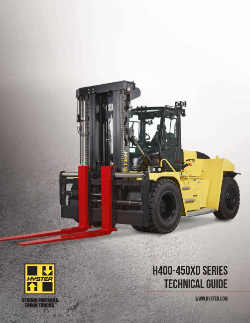
H400-450XD SERIES TECHNICAL GUIDE2H400-450XD DIMENSIONSCircled dimensions correspond to the line numbers on the tabulated chart inside the Technical Guide. Dimensions are in inches (millimeters).4-214-354-14-44-194-54-24-71-81-94-324-204-14-313H400-450XD SPECIFICATIONSCERTIFICATION: Hyster lift trucks meet the design and construction requirements of B56.1-1969, per OSHA Section 1910.178(a)(2), and also comply with the B56.1 revision in effect at time of manufacture. Certification of compliance with the applicable ANSI standards appears on the lift truck. Performance specifica-tions are for a truck equipped as described under Standard Equipment on this technical guide. Performance specifications are affected by the condition of the vehicle and how it is equipped, as well as by the nature, condition of the operating area, proper service and maintenance of the vehicle. If these specifications are critical, the proposed application should be discussed with your dealer.G E N E R A LDescriptionUnitsEnglishMetricEnglishMetric1-1Manufacturer HYSTER HYSTER 1-2Model designation H400XDS36H400XD361-3Powertrain / drivetrain Diesel Diesel 1-4Operator type SeatedSeated1-5Rated load capacity lbs kg 40,00018,14440,00018,1441-6Load center in mm 36914369141-8Load distance (1)in mm 431,086431,0861-9Wheelbasein mm 1383,5001483,750W E I G H T S2-1Total truck weight without load lbs kg 61,02427,68059,66427,0632-2Axle loading with load, front / rear lbs kg 93,20942,2797,8153,54591,79241,6367,8733,5712-3Axle loading without load, front / rear lbskg30,69113,92130,33313,75930,77413,95928,88913,104W H E E L S3-1Tire type Pneumatic Pneumatic 3-2Tire size, front 14.00 x 24PR 14.00 x 24PR 3-3Tire size, rear14.00 x 24PR 14.00 x 24PR 3-5Number of tires, front / rear (x driven)#4x / 24x / 23-6Tread width, front in mm 822,095822,0953-7Tread width, rear in mm 832,108832,108D I ME N S I O N S4-1Mast tilt, forward / back degrees10 / 1210 / 124-2Height of mast lowered (2)in mm 1463,6921463,6924-3Freeliftin mm 00004-4Lift height (top of fork)in mm 1483,7601483,7604-5Height, extendedin mm 2185,5172185,5174-7Height to top of operator compartment (open cab)in mm 1343,4011343,4014-8Seat height to SIP (3)in mm 872,204872,2044-19Overall length in mm 3127,9273228,1774-20Length to load face in mm 2165,4872265,7374-21Overall width of truck in mm 1152,9231152,9234-22Fork dimension in mm3.9 / 7.9 / 96100 / 200 / 2,4403.9 / 7.9 / 96100 / 200 / 2,4404-23Fork carriage type TypeDual function sideshiftDual function sideshift4-24Carriage width in mm 1052,6721052,6724-25-1Fork spread, min (in-in)in mm 33848338484-25-2Fork spread, max (out-out)in mm 942,393942,3934-30Sideshiftin mm 133********-31Ground clearance, under mast with load in mm 12299122994-32Ground clearance, center of wheelbasein mm 153********-34Minimum aisle width (add load length & clearance)in mm 2376,0202496,3364-35Outside turning radius in mm 1944,9342075,250P E R F O R M A N C E (T I E R 4)PERFORMANCE WITH TIER 4 FINAL CUMMINS QSB 6.7L ENGINE5-1Travel speed, with / without load mph km/h 16251625162516255-2Lifting speed, with / without load ft/min m/s 590.30650.33890.45980.505-3Lowering speed, with / without loadft/min m/s 980.50980.50980.50980.505-5Drawbar pull – 1 mph (1.6 km / h), with / without load lbs kN 36,19416137,09316536,41916237,0931655-6Drawbar pull – stall, with / without loadlbskN44,96220045,63620344,96220045,6362035-7Gradeability – 1 mph (1.6 km / h), with / without load %383339345-8Gradeability stall, with load / without load %50335134P E R F O R M A N C E (T I E R 3)PERFORMANCE WITH TIER 3 CUMMINS QSB 6.7L ENGINE5-1a Travel speed, with / without load mph km/h 16251625162516255-2Lifting speed, with / without load ft/min m/s 590.30650.33890.45980.505-3Lowering speed, with / without loadft/min m/s 980.50980.50980.50980.505-5Drawbar pull – 1 mph (1.6 km / h), with / without load lbs kN 36,19416137,09316536,41916237,0931655-6Drawbar pull – stall, with / without load lbskN44,96220045,63620344,96220045,6362035-7Gradeability – 1 mph (1.6km / h), with / without %383339345-8Gradeability – stall, with / without%50335134(1) Center of drive axle to front face of forks (2) Unladen with new tires (3) Full suspension seat in depressed position4H400-450XD SPECIFICATIONSCERTIFICATION: Hyster lift trucks meet the design and construction requirements of B56.1-1969, per OSHA Section 1910.178(a)(2), and also comply with the B56.1 revision in effect at time of manufacture. Certification of compliance with the applicable ANSI standards appears on the lift truck. Performance specifica-tions are for a truck equipped as described under Standard Equipment on this technical guide. Performance specifications are affected by the condition of the vehicle and how it is equipped, as well as by the nature, condition of the operating area, proper service and maintenance of the vehicle. If these specifications are critical, the proposed application should be discussed with your dealer.G E N E R A LDescriptionUnitsEnglishMetricEnglishMetric1-1Manufacturer HYSTER HYSTER 1-2Model designation H450XDS36H450XD361-3Powertrain / drivetrain Diesel Diesel 1-4Operator type SeatedSeated1-5Rated load capacity lbs kg 45,00020,41245,00020,4121-6Load center in mm 36914369141-8Load distance (1)in mm 421,069421,0691-9Wheelbasein mm 1383,5001483,750W E I G H T S2-1Total truck weight without load lbs kg 65,47729,70062,89328,5282-2Axle loading with load, front / rear lbs kg 101,50146,0408,9774,07299,64245,1978,2523,7432-3Axle loading without load, front / rear lbskg31,69614,37733,78115,35331,49114,28431,40514,245W H E E L S3-1Tire type Pneumatic Pneumatic 3-2Tire size, front 14.00 x 24PR 14.00 x 24PR 3-3Tire size, rear14.00 x 24PR 14.00 x 24PR 3-5Number of tires, front / rear (x driven)#4x / 24x / 23-6Tread width, front in mm 822,095822,0953-7Tread width, rear in mm 832,108832,108D I ME N S I O N S4-1Mast tilt, forward / back degrees10 / 1210 / 124-2Height of mast lowered (2)in mm 1493,7801493,7804-3Freeliftin mm 00004-4Lift height (top of fork)in mm 1483,7601483,7604-5Height, extendedin mm 2215,6052215,6054-7Height to top of operator compartment (open cab)in mm 1343,4011343,4014-8Seat height to SIP (3)in mm 872,204872,2044-19Overall length in mm 3117,9103218,1604-20Length to load face in mm 2155,4702255,7204-21Overall width of truck in mm 1152,9231152,9234-22Fork dimension in mm3.9 / 9.8 / 96100 / 250 / 2,4403.9 / 9.8 / 96100 / 250 / 2,4404-23Fork carriage type TypeDual function sideshiftDual function sideshift4-24Carriage width in mm 1162,9401162,9404-25-1Fork spread, min (in-in)in mm 33847338474-25-2Fork spread, max (out-out)in mm 1072,7121072,7124-30Sideshiftin mm 16404164044-31Ground clearance, under mast with load in mm 11270112704-32Ground clearance, center of wheelbasein mm 153********-34Minimum aisle width (add load length & clearance)in mm 2366,0032496,3194-35Outside turning radius in mm 1944,9342075,250P E R F O R M A N C E (T I E R 4)PERFORMANCE WITH TIER 4 FINAL CUMMINS QSB 6.7L ENGINE5-1Travel speed, with / without load mph km/h 16251625162516255-2Lifting speed, with / without load ft/min m/s 490.25550.28750.38830.425-3Lowering speed, with / without loadft/min m/s 980.50980.50980.50980.505-5Drawbar pull – 1 mph (1.6 km / h), with / without load lbs kN 36,19416136,86916436,19416136,8691645-6Drawbar pull – stall, with / without loadlbskN44,73719945,63620344,73719945,6362035-7Gradeability – 1 mph (1.6 km / h), with / without load %353236335-8Gradeability stall, with load / without load %44324633P E R F O R M A N C E (T I E R 3)PERFORMANCE WITH TIER 3 CUMMINS QSB 6.7L ENGINE5-1a Travel speed, with / without load mph km/h 16251625162516255-2Lifting speed, with / without load ft/min m/s 490.25550.28750.38830.425-3Lowering speed, with / without loadft/min m/s 980.50980.50980.50980.505-5Drawbar pull – 1 mph (1.6 km / h), with / without load lbs kN 36,19416136,86916436,19416136,8691645-6Drawbar pull – stall, with / without load lbskN44,73719945,63620344,73719945,6362035-7Gradeability – 1 mph (1.6km / h), with / without %353236335-8Gradeability – stall, with / without%44324633(1) Center of drive axle to front face of forks (2) Unladen with new tires (3) Full suspension seat in depressed position5H400-450XD SPECIFICATIONSPOWERTRAINSG E N E R A LDescriptionUnits EnglishMetric EnglishMetric1-1Manufacturer HYSTER HYSTER 1-2Model designation H400-450XD/S36H450XD361-3Powertrain / drivetrain Diesel DieselE N G I N E7-1Engine manufacturer / model Cummins / QSB 6.7L Cummins / QSB 6.7L 7-1a EPA tier compliance Tier 4F / Stage IVTier 3 / Stage III7-2Engine power output – rated hp kW 220@2000164@2000225@2000168@20007-2-1Engine power output – peak hp kW231@1800172@1800225@2000168@20007-3Rated speedrpm2,0002,0007-3-1Engine torque @ rpm (1 / min)lb-ft N-m700@1400949@1400700@1400949@14007-4Number of cylinders / displacement # / in3# / cm36 / 4086 / 6,6906 / 4086 / 6,690Turbocharger Type Variable geometry, water-cooled Wastegate, water-cooled7-8Alternator output Amps 1201207-9Electrical system voltage V 24247-10Batter voltage / nominal capacity V / Ah 24 / 10224 / 102D R I V E8-0Drive control / transmission Type Powershift transmission Powershift transmission 8-1Type of drive unitType Torque converter Torque converter 8-2Transmission manufacturer / type Type ZF 5WG211ZF 5WG2118-2-1Transmission speeds forward / reverse # 5 / 35 / 38-3Wheel drive / drive axle manufacturer / type Type AxleTech PRC1756W3H AxleTech PRC1756W3H 8-4Service brake Type Oil immersed (wet) disc Oil immersed (wet) disc 8-5Parking brakeTypeDry disc on drive axle Dry disc on drive axleM I S C10-1Operating pressure for attachments psi MPa 3,26322.53,26322.510-2Oil flow for attachments gpm l / m 261002610010-3Hydraulic oil tank, capacity gal l 542035420310-4Fuel tank, capacity gal l 803038030310-4-1DEF tank, capacity gal l1038N / AN / A 10-5Steering designType Hydraulic power steeringHydraulic power steering10-6Number of steering rotation# 4.4 4.410-7Sound pressure level at the driver’s seat LpAZ dB(A)72.776.010-7-1Sound power level during the workcycle LwAZ dB 100.4107.410-8Towing coupling, type DINType Yes / pinYes / pinH400XD/S36 MAST DIMENSIONS4-4 lift height (top of fork)4-2 Mast lowered ht.4-5 Overall extended ht.in mm in mm in mm 2-STAGE ONLY 147375014636922175517183465016341422536417212540017845172827167244620019449173147967263670020451673348467275700021053173468767H450XD/S36 MAST DIMENSIONS4-4 Lift Height (top of fork)4-2 Mast lowered ht.4-5 Overall extended ht.in mm in mm in mm 2-STAGE ONLY147375014937802215605183465016742302566505212540018246052867255244620019750053178055263670020752553378555275700021354053498855RATED L OAD v s L OAD C ENTER | D FSSFP P IN T YPE | U .S. C USTOMARYH400HD, H 400HDS H450HD, H 450HDSRATED LOAD VS. LOAD CENTER | DFSSFP PIN TYPE | U.S. CUSTOMARY R A T E D L O A D (l b s )LOAD CENTER (in)H400XD36, H400XDS36H450XD36, H450XDS36RATED L OAD v s L OAD C ENTER | D FSSFP H OOK T YPE | U .S. C USTOMARY H400HD, H 400HDS H450HD, H 450HDSRATED LOAD VS. LOAD CENTER | DFSSFP HOOK TYPE | U.S. CUSTOMARYLOAD CENTER (in)R A T E D L O A D (l b s )H400XD36, H400XDS36H450XD36, H450XDS36Model H400XDS36: 40,000 lbs. at 36” (18,144 kg at 914mm) load centerModel H450XDS36: 45,000 lbs. at 36” (20,412 kg at 914mm) load center Model H400XD36: 40,000 lbs. at 36” (18,144 kg at 914mm) load center Model H450XD36: 45,000 lbs. at 36” (20,412 kg at 914mm) load center Conversion Factor: 1.0” = 25.4 mm | 1 lb = 0.45 k• 2-stage (lower mast) to 147” (3750 mm) maximum fork height • 105” (2672 mm) carriage width (H400XD/S36)• 116” (2940 mm) carriage width (H450XD/36)• 96” (2440 mm) long forksSTANDARD FEATURES AND OPTIONSPERFORMANCE STD OPT Cummins QSB 6.7L diesel engine rated 220 hp tier 4 /164 kW stage IV*x Cummins QSB 6.7L diesel engine rated 220 hp tier 3 /164 kW stage IIIA*xTier 4 / stage IV compliant xTier 3 / stage IIIA compliant x Wastegate turbocharger, water cooled*x Variable geometry turbocharger, water cooled*x Hibernate Idle xOn-demand cooling fan*x120 amp alternator x Powertrain protection system xHeavy duty air intake xHigh mount exhaust xZF Transmission 5WG211 5-speeds fwd / 3-speedsreverse auto-shifting x AxleTech Drive Axle PRC1756 W3H with wet disc brakes x DRIVE STD OPT Travel speed limiter - unconditional and customeradjustable x Travel speed limiter - loaded (adjustable)x 14.00-24 24PR pneumatic bias ply drive and steer tires x14.00-R24 pneumatic radial drive and steer tires x 14.00-24 pneumatic shaped solid drive and steer tires x LIFT STD OPT On-demand load sensing hydraulic system x Automatic throttle-up when lifting (in neutral or inching)x2 Stage non free lift mast xMast tilt - 5° forward / 5° back x Mast tilt - 10° forward / 6° back x Mast tilt - 10° forward / 7° back x Mast tilt - 10° forward / 9° back x Mast tilt - 10° forward / 10° back x Mast tilt - 10° forward / 12° back x Pressure compensated lowering x Hydraulic system temperature protection with performancede-rate x HANDLING STD OPT Mast tilt indicator - mechanical x 105” (2680mm) Pin type dual function sideshift carriagewith simultaneous and individual fork positioner**x105” (2680mm) Quick disconnect hook type dual function sideshift carriage with simultaneous and individual fork positioner**xHANDLING (continued)STD OPT105” (2680mm) Quick disconnect hook type dual functionsideshift carriage with individual fork positioner and 1spare auxiliary function**x115” (2940mm) Pin type dual function sideshift carriagewith simultaneous and individual fork positioner***x115” (2940mm) Quick disconnect hook type dual functionsideshift carriage with simultaneous and individual forkpositioner***x115” (2940mm) Quick disconnect hook type dual functionsideshift carriage with individual fork positioner and 1spare auxiliary function***x96” (2440mm) Long x 3.9” (100mm) thick x 7.9”(200mm) wide pin type forks with standard taper**x96” (2440mm) Long x 3.9” (100mm) thick x 9.8”(250mm) wide pin type forks with standard taper***xPin type forks (various sizes)xHook type forks (various sizes)xERGONOMICS STD OPTOpen operator compartment (without doors & screens)xEnclosed operator cabin xPowered tilt operator compartment for service xManual tilt operator compartment for service xIsolated cabin mounting for low noise and vibration xOperator presence system xMechanical suspension seat xAir suspension seat xDeluxe air suspension seat xLow backrest seat xHigh backrest seat xArmrest on left side xCloth seat cover xVinyl seat cover xSeat heating xSeat ventilation x2-point high visibility seatbelt xLateral seat sliding mechanism xFloor mat xInterior dome light xFront, top and rear wipers x“H”-pattern front wiper x“I”-pattern front wiper xFront and rear window defrosters xRight side door (enclosed operator cabin)xHandrails for exit and entry xRain top x* Standard or optional in select markets or select models.** H400XD36 and H400XDS36*** H450XD36 and H450XDS3667STANDARD FEATURES AND OPTIONSERGONOMICS (continued)STD OPTWire mesh installed on top of operator compartment x7” Integrated Performance Displayx Touchpoint ™ mini levers hydraulic control integrated in control armxJoystick hydraulic control integrated in control arm xSteering wheel with spinner knob x Directional control lever on steering column xHyster Monotrol pedal directional controlx Directional control switch (integrated into control arm)x Directional control on joystick x Park brake - manual x Interior wide angle mirrors xHeater with adjustable speed fan x Telescoping & tilting steering columnx 24-12 DC converter with 1 socket and 2 USB outlets x24-12 DC converter with 2 sockets and 2 USB outlets x Air conditioning and automatic climate control x Reading lightx Sun shades on top and rear (standard with air conditioning and automatic climate control)x Sun visors front windowx Cloth trainer seat with 2-point seatbelt x Recirculation fan (enclosed operator cabin)xAccessory mounting bracket on cab front right pillar x Document holder on cab front right pillar x Heated top- and/or rear windowx Radio preparation with 2 speakers and antennax VISIBILITYSTD OPTSteel bars on top of cab (open operator compartment)x Top window with armoured glass (enclosed operator cabin)xSteel bars under armoured glass top window (enclosed operator cabin)x Exterior mirrors mounted to handrails x Rear view camera system x Radar object detection system x Halogen work lightsxHigh Performance LED work lightsx Two Halogen head lights mounted on front fenders xTwo LED head lights mounted on front fenders x Two mast mounted work lights xFour cabin mounted work lightsx Two rearward work lights mounted on the cabin x LED stop / tail / brake lightsxTurn signals, hazard & marker lights (LED)xOPERATIONSTD OPTAir horn 112 dBA x Electric horn 105 dBAx Visible alarm – amber strobe light, keyswitch activated x Audible alarm – reverse direction activated 82–102 dB(A), self-adjusting xForward motion alarmx Seatbelt interlock for engine start and truck operation x Air conditioning shut-off with open door x Automatic engine shutdown with timer x Lockable battery disconnect switch xBattery jump start connector (NATO plug)x Truck Start with key switch and start button x Operator password (display) for truck start xFuses replaced by electric circuit breakers x Non-lockable fuel cap xLockable fuel capx Fuel strainer in fuel filler neckx Hyster Tracker wireless asset management - access / verificationx Hyster Tracker wireless asset management - monitoring xAuto greasing system for base truck x Centralized greasing system for top end mast x 24 volt electrical system xEngine block heater 110 or 240 volt x Steer wheel lug nut protection xFront and rear mud guards x Lifting eyes - 2 front and 2 rearxAPPEARANCESTD OPTHyster yellow paint base truck xSpecial paint base truckxSUPPLEMENTALSTD OPTLiterature package x Operator’s manual xCE certification*x Warranty: 12 months / 2,000 hours parts & labor manufacturer’s warranty*x* Standard or optional in select markets or select models.** H400XD36 and H400XDS36*** H450XD36 and H450XDS36Hyster Company P.O. Box 7006Greenville, North Carolina 27835-7006Part No. H400-450XD-TG 11/2021 Litho in U.S.A.5019HBC5SP001_E_EN-US_V1R1_112021Visit us online at or call us at 1-800-HYSTER-1.© Hyster Company. 2021, all rights reserved. Hyster and are trademarks of Hyster-Yale Group, Inc. Hyster products are subject to change without notice. Trucks may be shown with optional equipment.。
东风南充450左置式LNG气瓶技术协议
富瑞编号:FRJX120214-5技术协议东风南汽带增压供气系统卡车、450L气瓶左侧置式需方(甲方):东风南充汽车有限公司供方(乙方):张家港富瑞特种装备股份有限公司2012年2月技术协议1.概述东风南充汽车有限公司(以下简称甲方)和张家港富瑞特种装备股份有限公司(以下简称乙方)经友好协商,签订450L气瓶左侧置式车用LNG燃料贮罐(带自增压)及供气系统技术附件。
本技术附件随同合同生效。
2.技术参数气瓶在正常运行情况下,气瓶压力满足甲方要求,但不高于 1.59MPa;气化器出口压力不低于气瓶压力0.05MPa。
2.1车用气瓶参数公称容积: 450L有效容积: ≈405L工作压力:1.59MPa气瓶试验压力(内胆):3.18MPa(气压)主体材料:06Cr19Ni10(SUS304或304)内胆安全阀开启压力: 1.75MPa(一级安全阀);2.85MPa(二级安全阀)静态蒸发率: <2.1%/d (LNG,20℃,0.1MPa条件下)绝热型式:高真空多层绝热设备净重(主体设备):≈305kg最大充装量:≈172kg(按LNG密度426kg/m3)具体外形尺寸见附图2.2汽化器参数管程介质:LNG壳程介质: 发动机冷却水汽化能力:80Nm3/h管程进口温度:-162℃管程出口温度: ≤30℃壳程进口温度:≥+90℃壳程出口温度:≤+70℃水流量≥18L/min(发动机提供流体动力且保证该流量)设计压力(管程): 2.5MPa工作压力(管程):2.2MPa气密试验压力(管程):2.88MPa2.3稳压器参数稳压器出厂设定压力值:0.86MPa流量:≥80Nm3/h具体外形尺寸见附图3.结构说明3.1结构形式:气瓶的内胆、外壳均选用优质奥氏体不锈钢制造。
气瓶采用高真空多层绝热,并装有经过特殊处理的吸附剂。
瓶上设有一、二级安全阀、进出液口、限流阀、气相口、电容式液位计、压力表和瓶内压力自动调压装置及自增压(稳压)系统.气瓶出口带一个手动截止阀。
- 1、下载文档前请自行甄别文档内容的完整性,平台不提供额外的编辑、内容补充、找答案等附加服务。
- 2、"仅部分预览"的文档,不可在线预览部分如存在完整性等问题,可反馈申请退款(可完整预览的文档不适用该条件!)。
- 3、如文档侵犯您的权益,请联系客服反馈,我们会尽快为您处理(人工客服工作时间:9:00-18:30)。
H54RA, H51RA, H52RA, H53RA
DESCRIPTION The Connor-Winfield H54RA, H51RA, H52RA, and H53RA are 3.3V HCMOS, Surface Mount, Fixed Frequency Crystal Oscillators (XO) designed for use in all applications requiring precision clocks. FEATURES
元器件交易网
THE CONNOR-WINFIELD CORP.
2111 COMPREHENSIVE DRIVE. AURORA, IL 60505. FAX (630) 851-5040. PHONE (630) 851-4722.
PRODUCT
PACKAGE CHARACTERISTICS
Package Hermetically sealed metal package
TABLE 6.0
Note: 1) Inclusive of calibration @ 25°C, frequency vs. temperature stability, supply voltage change, load change, shock and vibration, 10 years aging. 2) Oscillator output is enabled with no connection on pin 1
D AT A
SHEET
CW ED OSCILLATORS 3.3V 8 PIN DIP TRI-STATE CLOCK OSCILLATOR
ABSOLUTE MAXIMUM RATINGS
PARAMETER Storage Temperature Supply Voltage UNITS (Vcc) MINIMUM -55 -0.5 NOMINAL MAXIMUM 125 7.0 UNITS °C Vdc TABLE 2.0 (Fo) 1.0 -20 100 20 MHz ppm 1 TABLE 1.0 NOTE
ORDERING INFORMATION
HSM633 - 125.00 MHz H54RA 80.00MHz
CLOCK SERIES CENTER FREQUENCY
Specifications subject to change without notice. DATA SHEET #: Hc151 PAGE 1 OF 1 REV: 03 DATE: 09/11/06
MODEL SPECIFICATIONS: MODEL H54RA
Frequency Range Frequency Tolerance:
MODEL H51RA
Frequency Range Frequency Tolerance: (Fo) 1.0 -25 100 25 MHz ppm 1
MODEL H52RA
PACKAGE
INPUT CHARACTERISTICS
Enable Voltage Disable Voltage Enable Time Disable Time
HCMOS OUTPUT CHARACTERISTICS
PARAMETER LOAD Voltage (High) (Low) Current (High) (Low) Duty Cycle at 50% of Vcc Rise / Fall Time 10% to 90% Start-Up Time Jitter (BW=10Hz to 20MHz) Jitter (BW=12kHz to 20MHz) MINIMUM Vcc-0.5V -8 45 NOMINAL MAXIMUM 15 0.4 8 55 6 10 5 1 UNITS pF Vdc Vdc mA mA % nS mS ps rms ps rms
aCopyright 2001 Connor-Winfield all rights reserved.
Frequency Range Frequency Tolerance: (Fo) 1.0 -50 100 50 MHz ppm 1
MODEL H53RA
Frequency Range Frequency Tolerance: (Fo) 1.0 -100 100 100 MHz ppm 1 TABLE 3.0 MINIMUM 0 (Vdd) 1.544 to 31.999 MHz 32 to 49.999 MHz 50 to 66.999 MHz 67 to 100 MHz (Icc) (Icc) (Icc) (Icc) 3.0 NOMINAL 3.3 MAXIMUM 70 3.6 15 20 25 40 UNITS °C Vdc mA mA mA mA TABLE 4.0 (Vih) (Vil) > 70% Vdd < 30% Vdd 10 100 Vdc Vdc mS nS 2 NOTE
OPERATING SPECIFICATIONS
PARAMETER Operating Temperature Range Supply Voltage Supply Current
1.0 to 100 MHz 3.3V OPERATION TRI-STATE ENABLE/DISABLE OVERALL FREQUENCY TOLERANCE: H54RA ±20ppm H51RA ±25ppm H52RA ±50ppm H53RA±100ppm TEMPERATURE RANGE: 0 to 70°C HERMETICALLY SEALED PACKAGE RoHS 5/6 COMPLIANT
TABLE 5.0 NOTE
SOLDER PROFILE
Temperature 260°C 220°C 180°C 150°C 120°C 260°C
(Voh) (Vol) (Ioh) (Ioh)
50 3 -
0 120 S Max. Time 10 S 60 S Max. 360 Sec. Max.
