SK-3系列智能手动操作器说明书
K3用户手册
松科手持式激光焊接机用户手册(V3.0版)说明书

SKL20版本松科手持式激光焊接机用户手册请您在使用该系统之前请务必阅读该手册⌝本手册内容是双摆手持激光焊接系统用户手册⌝先仔细阅读该手册,保证正确电气连接SKL-V3.0手持激光焊接机用户使用手册(暂定版)V3.0版本+双摆焊接头福建松科机器人有限公司地址:中国(福建)自由贸易试验区厦门片区港中路1283 号2 号楼2 单元二层电话:189-****3999,************网址:版权声明:福建松科机器人有限公司(以下简称松科公司)保留所有权力。
松科公司保留在不事先通知的情况下,修改本手册中的产品和产品规格等文件的权力, 同时保留对本产品附带的任何文档进行修改的权力。
使用者在使用本文所述产品时请仔细阅读本手册,松科公司不承担由于使用本手册或本产品不当,所造成直接的、间接的、特殊的、附带的或相应产生的损失或责任。
松科公司不承担以下直接的或间接的责任或损失:⌝用户使用本手册或本产品不当⌝用户没有遵循相关的安全操作规程所造成的损失自然力造成的损失,使用中的机器有危险,使用者有责任在机器中设计有效的出错处理和安全保护机制,松科公司没有义务或责任对由此造成的附带的或相应产生的损失负责。
产品广泛应用于电池、汽车、汽车配件、电子电路、光纤通讯器件、手机、家用电器、厨卫五金、精密器械、仪器仪表、金银首饰、医疗器件、太阳能、眼镜行业、马达行业等。
产品深受各行各业的肯定与赞扬,在客户中有着良好的口碑和信誉。
●支持工艺库存储;●6 种出光模式(―、○、◎、⊙、△、8);●光斑可调(0-5)mm;●控制屏直接数字化设置送丝机参数;●支持送(0.8、1.0、1.2、1.6)不锈钢、碳钢、铝焊丝;●邀请专业国际激光友人翻译,同时获有中、英、韩、日、俄、繁、法、西班牙、以色列九国语言;●系统时时监控运行状态,对激光器、冷水机、控制板运行监控并收集运行状态;●完美取代部分传统氩弧焊、电焊在薄板不锈钢板、铁板、铝板等金属材料方面焊接;●重量轻、体积小、人体工学设计握感舒适;●安全锁触碰出光;●操作简易上手,对操作人员要求极低;●抗干扰强;●全密封结构内置水路、风路;●配置自主研发控制系统;●焊缝美观,速度快、无焊痕,无变色,无需后期打磨使用激光焊接系统注意事项1. 双摆工业焊接头包含了激光器,水冷机,激光焊接系统,激光焊接头多个控制模块,为了避免被干扰,确保远离氩弧焊机二保焊机和干扰较大的相关设备,确保安全距离保持在5 米以上。
3Q04说明书(2010.01.07new)
SK-3Q04氢焰色谱仪注 意 事 项非常感谢您使用上海神开SK-3Q04氢焰色谱仪,您在安装和使用本仪器时,请先阅读以下注意事项: 用电安全● 本仪器使用的电源线是单相三线的接法,其中除相线、零线外,地线必须与大地牢固接通,地线应扎入地下2米左右(用≥Ф20mm 的金属铁棒或≥30mm 角铁制作)。
不能用零线作地线。
● 本仪器使用的是单相220V50Hz 用电电源,仪器在移动或更换用电插头座时,先要检查供电电网的电压值、极性、功率等。
只能证明其符合要求时方可接入仪器。
● 更换电源保险丝时注意要符合其要求,其具体规格在说明书中可查到。
或仔细检查换下的保险丝规格,换上同规格保险丝。
● 检修时若需拆开仪器盖面板用必须注意先断开电源插头座。
● 仪器的工作程序是固化的,请不要随意改动。
防止烫伤● 仪器FID 、色谱柱炉工作时有加热温度,在关机检修时可能温度来不及散发,应注意防止烫伤事故发生。
用气安全● 仪器工作时使用氢气发生器,注意将氢气排出室外。
● 快速色谱仪气路系统应严格检漏,保证无泄漏。
● 氢气发生器产氢后消耗水,当水位低于报警点时应加去离子水或蒸馏水。
加的水不要超出上限水位线。
● 空气压缩机储气桶内的水应该经常放掉,放毕水后应将放水阀关闭。
系统正常工作时仪器出厂时已将压力、流量、分析周期(C 1-C 5 样品气输入端的玻璃砂芯过滤球、滤芯等预处理系统需要经常更换(更换方法见本说明书的有关内容),以保证系统的正常工作。
天然气组份的保留时间)等调整好,用户不必再作任何调整。
样品管线由于经常容易受水气的污染,发现后需要作管线反吹。
触摸屏设定时触摸屏必须保持清洁,不要用油污的手操作系统。
为了保持系统的可靠工作,请用触摸屏的操作笔设置操作条件或与外界通信。
数据上传时3Q04色谱仪在进行数据文件上传时将停止实时采样和实时的数据通讯,仅进行数据文件的传输;3Q04传输完数据文件后自动恢复到正常工作状态;在正常工作状态下不要进行文件传输,防止漏测资料。
三姆斯·工业支持-3SK2诊断显示器说明书

FAQ 04/2016Working with the 3SK2 diagnostic displayEasy diagnosis and transferring of safety programS i e m e n s A G 2016 A l l r i g h t s r e s e r v e dThis entry is from the Siemens Industry Online Support. The general terms of use (/terms_of_use ) apply.Security informa-tionSiemens provides products and solutions with industrial security functions that support the secure operation of plants, solutions, machines, equipment and/or networks. They are important components in a holistic industrial securityconcept. With this in mind, Siemens’ products and solutions undergo continuous development. Siemens recommends strongly that you regularly check for product updates.For the secure operation of Siemens products and solutions, it is necessary to take suitable preventive action (e.g. cell protection concept) and integrate each component into a holistic, state-of-the-art industrial security concept. Third-party products that may be in use should also be considered. For more information about industrial security, visit /industrialsecurity . To stay informed about product updates as they occur, sign up for a product-specific newsletter. For more information, visit .Table of contents1 Product overview ............................................................................................... 5 2Controlling and monitoring .............................................................................. 6 2.1 Preparation in the software .................................................................. 8 2.1.1 Filling in of project information ............................................................. 8 2.1.2 Preparation for detailed status information ........................................ 10 2.2 Displaying of plant information ........................................................... 11 2.2.1 Reading out of project information ..................................................... 11 2.2.2 Reading out of status information ...................................................... 12 2.3 Fault diagnostic .................................................................................. 14 3Transferring of projects by the help of the diagnostic display (15)3.1 Preconditions ...................................................................................... 15 3.2 Procedure ........................................................................................... 17 3.3 Use cases ........................................................................................... 20 3.3.1 Fast device exchange ........................................................................ 20 3.3.2 Fast commissioning of same application . (21)4 Contact/Support (22)S i e m e n s A G 2016 A l l r i g h t s r e s e r v e dQuestionWhich functionality can be realized by the 3SK2 diagnostic display (MLFB 3SK2611-3AA00)?S i e m e n s A G 2016 A l l r i g h t s r e s e r v e dAnswerThe diagnostic display offers easy fault location without PC/PG. It supports fast problem solution by detailed fault messages. There is no engineering in advance in the basic module necessary to connect the display. The connection outside of the control cabinet allows easy access.Furthermore with two integrated memory slots you can use the diagnostic display for saving and transferring of projects. This simplifies commissioning of identical machinery and allows quick device exchange in case of fault. It is especially helpful by use of the 22,5 mm width basic module which has no exchangeable memory module.S i e m e n s A G 2016 A l l r i g h t s r e s e r v e d1Product overviewBeside the 3SK2 diagnostic display (MLFB 3SK2611-3AA00) the 3RK3 diagnostic display (MLFB 3RK3611-3AA00) still exists. The following table shows an overview of compatibility and functionality.Table 1: Compatibility diagnostic display 3SK2 and 3RK3It is not possible to transfer projects with the 3RK3 diagnostic display.For both displays you need a connection cable, which is available in different lengths and flat and round version: MLFB 3UF793*-0*A00-0.S i e m e n s A G 2016 A l l r i g h t s r e s e r v e d2Controlling and monitoringBesides the fault detection via monitoring function within the software, the diagnostic display helps for easy problem analysis without connection of PC or PG by detailed error messages. Even in case of no failure project and status information are helpful which are available at the display.In the following image you can see a simplified menu overview of the diagnostic display.Figure 1: Menu structure diagnostic displayS i e m e n s A G 2016 A l l r i g h t s r e s e r v e dMenu items have no fixed numbering and can be hidden in the display depending on the connected device and current status. The menu items …Status Info“, …Status“ and …Configuration Transmission “ are shown in detail as they are more relevant for this FAQ.In the menu item …Status “ the state of all in- and outputs can be read out (e.g. “Switching output Switching ON Condition not satisfied ”). Comprehensive project information (e.g. Config-CRC, Project Engineer) can be found in the menu item …System Configuration “. In case of troubleshooting the menu item …Status Info “ is helpful. Here you can see detailed error messages and warnings. All status information which are available in Safety ES can be shown at the display. If no errors are present the menu item is empty.By means of an example with guard door monitoring and emergency stop theeasy diagnose in case of fault and no fault will be shown subsequently.Figure 2: Logic plan application exampleS i e m e n s A G 2016 A l l r i g h t s r e s e r v e d2.1 Preparation in the softwareThere is no previous engineering of the diagnosis display in the software necessary. The display can be plugged in without any effort in advance.For easy error tracking it is helpful to assign informative names to the function elements which will be shown in the diagnostic display. Furthermore all added project / hardware information can be read out in the display.2.1.1 Filling in of project informationIn …Identification“ and …Configuration“ information regarding project and hardware configuration can be filled in.Figure 3: Filling in of project informationS i e m e n s A G 2016 A l l r i g h t s r e s e r v e dFigure 4: Filling in of hardware informationIn the main system the diagnostic display can be added on system slot 1 optionally. This is only for documentation purpose and is not mandatory. All project information can be found in the diagnostic display in the menu item …System C onfiguration“.S i e m e n s A G 2016 A l l r i g h t s r e s e r v e d2.1.2 Preparation for detailed status informationFor easy diagnose it is advisable to name the function elements.Figure 5: Naming of function elementsBy double-clicking on the respective function element a symbolic name can be assigned in the window …properties“. T his name is displayed as further information in the diagnostic display. It is helpful to assign names for all input elements (e.g. “Emergency Stop”) as well for all output elements (e.g. “F -output”).S i e m e n s A G 2016 A l l r i g h t s r e s e r v e d2.2Displaying of plant informationTo read out information at the diagnostic display an active connection to the energised basic module must be established. There mustn’t be any additional connection from the PCs/PGs via the diagnostic display to basic module. In this case the display is locked.2.2.1Reading out of project informationInformation regarding the project or hardware can be found in the menu item …System Configuration “. In the menu item …Project“ details regarding Config- CRC, Time Stamp, Release and Project Engineer are listed. Certain information are provided automatically from the system. Other information like …Project Engineer “ are only available if the corresponding fields were filled in in thesoftware (see chapter 2.1.1 Filling in of project information).In the menu item …Slot 3“ details regarding the used basic module can be found.Table 1: Project- and HardwareinformationS i e m e n s A G 2016 A l l r i g h t s r e s e r v e d2.2.2 Reading out of status informationThe full information concerning input and output elements can be found in the menu item …Status“.The elements are displayed as follows:Figure 6: Displaying of status/status infoFor this example the guard door is opened, the Emergency Stop was pushed and released but not acknowledged yet. Thus the output is not activated. These information can be read out in …Status / Input Elements “ as well …Status / Output Elements “.E-Stop 1 (symbolic name of the element),S i e m e nsA G 2016 A l l r i g h t s r e s e r v e dProtective Door (type of function element)You can read out status information which are available as element status in the Safety ES (e.g. …Timer running “, …Wa iting for Start“).S i e m e n s A G 2016 A l l r i g h t s r e s e r v e d2.3Fault diagnosticTroubleshooting with the help of the diagnostic display will be explained by means of the application example of figure 2. There is a cross circuit between input 1 and input 2 of the emergency stop with element number 1.In case of fault detailed information can be found in the menu item “Status Info “. According to the default setting of the display the status info will be directly shown on the start screen in case of a fault (Setting adjustable in …Display Settings/ Statu s Info“)Table 2: Error messages in case of Cross-CircuitThe same procedure applies to other faults like discrepancy fault or fault within the feedback circuit. Below the element you find then the error message ‚Dis crepancy violated ‘ or ‚Feedback Circuit invalid ‘. All element messages which are available in Safety ES can be shown on the diagnostic display as well.S i e m e n s A G 2016 A l l r i g h t s r e s e r v e d3Transferring of projects by the help of the diagnostic displayThe 3SK2 diagnostic display (MLFB: 3SK2611-3AA00) has two internal memory slots at which Safety ES projects can be stored.NoteThis functionality is only available for the diagnostic display 3SK2611-3AA00. The 3RK3 diagnostic display (MLFB: 3RK3611-3AA00) has no internal memory slots and it is not possible to connect it to the 3SK2.3.1PreconditionsTo be able to transfer Safety ES projects from or to the display an activeconnection to the running basic module must be established. Furthermore it is not possible to have an additional connection from the basic module to the PG/PC via the diagnostic display. In this case the display is locked. Transferring of projects is possible with both types of 3SK2 basic modules (3SK2112, 22,5mm width/ 3SK2122, 45 mm width) as well as with the 3RK3 Advanced and 3RK3 ASIsafe.Preconditions for saving projects in the diagnostic display/ reading configurations from the deviceTo save projects within the diagnostic display 2 memory slots are available. If a project was already stored on the selected memory slot and you read out a new configuration on the same memory slot, the old one will be replaced. There are no restrictions for reading out configurations. It is possible to read out not approved and approved configurations. The device can be in configuration or safety mode. If the protection level ‚write protection‘ was selected by password for the project which will be read out from the basic module, the protection level will be copied to the configuration in the display as well.S i e m e n s A G 2016 A l l r i g h t s r e s e r v e dHinweisThe protection level ‚Read Protection ‘ should not be activated in the basicmodule (3SK“/3RK3). In this case it is not possible to read out any configuration. Thus it is not possible to copy a project with Read Protection. This can be set after download via the Safety ES Tool.Preconditions for transferring of projects to the basic module It is possible to transmit a project to the device on condition that: - Device is running in configuring mode. - No password for device access is set.- The configuration on the basic module is not approved or there is no configuration on the basic moduleIf one of these conditions is not fulfilled the download of the project fails. In case that the download fails it is possible to download the project by resetting thebasic module to factory settings via reset button (See manual 3SK2 chapter 8.1/ manual 3RK3 chapter 6.4.4.5). Afterwards the device runs up in configuring mode and the project can be downloaded.DANGERAccidentally start possibleThe operator has to ensure that the configuration is downloaded to the correct machine, otherwise it can lead to a dangerous situation.NoteThe menu …factory settings“ in the diagnostic display refers only to the diagnostic display and not to the basic module. By executing the command the configurations in the diagnostic display among others will be deleted.S i e m e n s A G 2016 A l l r i g h t s r e s e r v e d3.2 ProcedureFor reading out a configuration from the basic module an active connection to it is necessary. Downloading a project from Safety ES to the diagnostic display is not possible without the basic module.Saving a configuration in the diagnostic displaySelect the favoured Memory Slot e.g.Table 3: Backup of a projectThe project is now saved in the selected memory slot in the diagnostic display.S i e m e n s A G 2016 A l l r i g h t s r e s e r v e dThe project information of the saved project (Name, Project Engineer, Company, Config-CRC, Time Stamp, Approval, Cycle Time …) can be read out in the corresponding memory slot.Transmission of a configuration from the diagnostic display to the basic moduleTable 4 Write project to deviceThe configuration is now saved in the basic module.The project information of the downloaded project (Name, Project Engineer, Company, Config-CRC, Time Stamp, Approval, Cycle Time …) can be read out in “System Configuration/ Project”.S i e m e n s A G 2016 A l l r i g h t s r e s e r v e dNoteWhen downloading an approved configuration to the basic module the device first stays in configuring mode. To change to safety mode turn off and on the basic module. After running up, the device changes automatically to safety mode.S i e m e n s A G 2016 A l l r i g h t s r e s e r v e d3.3Use cases3.3.1 Fast device exchangeIn case of a faulty basic module the approved configuration can be transferred fast and easily to the new basic module by the help of the diagnostic display. Thus the plant operation can continue quickly.Figure 7: Fast device exchange NoteBack up the Safety ES project straight after successful commissioning of the safety application to the diagnostic display.3 Transferring of projects by the help of the diagnostic displayWorking with the 3SK2 Diagnostic displayEntry-ID: 109482844, V1.0, 04/201621S i e m e n s A G 2016 A l l r i g h t s r e s e r v e d3.3.2 Fast commissioning of same applicationBy help of the possibility to download projects from the diagnostic display the commissioning of identical machinery can be sped up. After successful function test and approving once the safety program can be downloaded to the other machinery.Figure 8: Fast commissioning of identical machinery4 Contact/SupportWorking with the 3SK2 Diagnostic displayEntry-ID: 109482844, V1.0, 04/201622Si emensA G2016Al lrigh tsr ese rv ed4 Contact/SupportSiemens AGTechnical AssistanceTel: +49 (911) 895-5900Fax : +49 (911) 895-5907Mail: ******************************** Internet: www.siemens.de/automation/support-request。
SK-239B常用操作指令
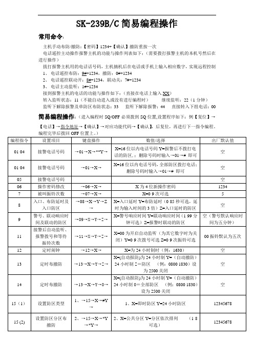
SK-239B/C简易编程操作
常用命令:
主机手动布防/撤防:【密码】1234+【确认】撤防重按一次
电话遥控主动操作报警主机的功能与操作列表如下:(需要拨打报警主机的本机号然后在进行操作)
拔打报警主机用的电话话号码,主机摘机后在电话或手机上输入相应数字,实现远程控制
1、电话遥控布防:9#+1234,撤防:0#+1234
2、电话遥控联动开:8#+1234,联动关:7#+1234
3、电话主动监听:1#+1234
接到报警主机的电话的功能与操作如下:(直接在电话上输入XX)
转入监听状态:11(不能自动进入或没有进行编程时)继续监听:22(1分钟)
监听下解除报警及单防区布防状态:33 监听下解除报警:44 直接转入下组电话:00 简易编程操作:(进入编程时SQ/OFF必须拨到SQ位置,设置程序如下:例【复位】→【电话】→指令地址→【确认】→对应功能代码→【确认】,后复位,再进行下一指令编程。
特别注意!编程操作完毕时,请把‘授权/关闭’(SQ/OFF)开关,拔向“OFF"授权关闭的位置上,否侧机盖上锁以后有可能被人为重新编程设定,使程序错乱或错误删除报警电话号码。
SK-3系列智能手动操作器说明书
热偶或高温计输入: 应采用与热偶对应的补偿导线作为延长线,最好有屏蔽。
RT D(铂 电阻) 输入: 三根 导线的 电阻必 须 相 同,每根 导线 电 阻不 能超过15Ω。
3、 通电 设 置 仪 表接 通 电 源后 进 入自 检(自检 状态见 下图),自检 完 毕后 ,仪 表
在点动输出时,可以实现阀位点动关小
增加键:用于增加数值
带打印功能时,用于手动打印
在点动输出时,可以实现阀位点动开大
2、仪 表配线
仪表在现场布线注意事项:
PV 输 入 (测 量 输入)
2
1) 减小 电 气干 扰,低 压 直流 信号 和传感 器输入 的连线 应 远 离强 电 走线。如果做不到应采用屏蔽导线,并在一点接地。
第一输出零点
0~1. 2 00
第 一输出 零点 迁移量(见注2 )
5
名称 第一输出比例
设定范围(字)
说明
0~1. 20 0
第一输 出的放 大比 例(见注2)
第一输出下限
全量程
第一输出的下限量程
第一输出上限 第二输出方式 第二输出零点
全量程 0~2
0~1. 20 0
第一输出的上限量程
2 T=0: 外给定 变送输 出 2 T=1: 阀位反 馈值变 送输 出 2 T=2: 模拟控 制输出
DC24V/2A(大) 见备注
≤30mA
综合参数
测量 精度 0. 2%FS 1字
设定方式 面板轻触式按键数字设定;参数设定值密码锁定;设定值断 电永久保存。
-1999~9 9 99外给 定显 示、 设定 值显 示、 控制 目标 值显 示,
SK系列操作说明书
于主体故障引起的停产等次生性损失,我公司概不负责。
2
目录
1. 本书的使用方法··················································· 5 2. 使用时的注意事项················································· 6 3. 产品构成························································· 11 4. 各部位的名称····················································· 12 5. 本体模块的连接和设备安装
将不能进行称重。具体请参考 5-2-2 章节。
排除静电的影响
!
·当测量物的包装袋、容器等使用绝缘物时,所带的静电会导致测量发生误差。
请使用混有导电材料的风防盖,或者金属容器。
·为了防止静电损坏称重模块,请将模块通过设备外框接地。
排除风的影响
·称重部的周围请一定做好防风罩,排除风的影响。当包装袋或容器体积增大
! 警告
不要在温度、湿度过高的环境下使用 ·可能导致触电或者电路短路。 ·本机的使用温湿度范围是:10~30℃,80%RH 以下。 本机的 DC24V 电源请专门配置,请不要与其他的 DC24V 驱动机器共用 ·如果从其他驱动机器的电线侵入的强干扰,可能导致本机的误动作。
!
·如果从其他驱动器带来冲击电流,可能导致本机无法正常启动。 ·根据本机的电路结构,也可能导致其他驱动器无法正常动作。
SKSC Series 低档位侧推型触摸开关说明书

Side push typePart number SKSCLDE010Type Surface mountOperating force 1.6NOperating direction Side pushTravel0.2mmOperating life(5mA 5V DC)100,000 cyclesInitial contact resistance100mΩ max.Guide bosses WithSeries type Sharp feeling typeOperating temperature range-30℃ to +85℃Rating (max.)50mA 12V DCRating (min.)10µA 1V DCElectricalperformanceInsulation resistance100MΩ min. 100V DC for 1min.Voltage proof100V AC for 1 min.Durability Vibration10 to 55 to 10Hz/min., the amplitude is 1.5mm for all thefrequencies, in the 3 direction of X, Y and Z for 2 hoursrespectivelyEnvironmentalperformanceCold-30±2℃ for 96hDry heat80±2℃ for 96hDamp heat60±2℃, 90 to 95%RH for 96hMinimum order unit (pcs.)Japan5,0001.25mm Height Low-profile Side Push Type (Surface Mount) SKSC SeriesExport5,000 PhotoDimensionsLand DimensionsViewed from switch mounting faceCircuit DiagramPacking SpecificationsTaping1 reel5,000 Number of packages(pcs.)1 case / Japan50,00050,0001 case / exportpackingTape width (mm)12Export package measurements (mm)395×395×205 Soldering ConditionsCondition for Reflow1. Heating methodDouble heating method with infrared heater.2. Temperature measurementThermocouple 0.1 to 0.2 Φ CA(K) or CC(T) at solder joints (copper foil surface). A heat resisting tape should be used for fix measurement.3. Temperature profile(1) The above temperature shall be measured of the top of switch. There are cases where PC board's temperature greatly differs from that of the switch, depending on the material, size, thickness of PC board's and others. Care, should be taken to prevent the switch's surface temperature from exceeding 260℃.(2) Soldering conditions differ depending on reflow soldering machines. Prior verification of soldering condition is highly recommended.Manual SolderingItems ConditionSoldering temperature350℃ max.Duration of soldering3s max.Capacity of soldering iron60W max.1. Consult with us for availability of TACT switch™ washing.2. Prevent flux penetration from the top side of the TACT switch™.3. Switch terminals and a PC board should not be coated with flux prior to soldering.4. The second soldering should be done after the switch returns to normal temperature.Notes are common to this series/models.1. This site catalog shows only outline specifications. When using the products, please obtain formalspecifications for supply.2. Please place purchase orders for taping products per minimum order unit (1 reel or a case).3. For φ330mm diameter reel requirements, please contact us.4. Please contact us for automotive use products.。
sk无叶风扇遥控器使用说明

sk无叶风扇遥控器使用说明SK无叶风扇遥控器使用说明SK无叶风扇是一种新型的风扇产品,它的特点是没有传统风扇的叶片,而是通过空气动力学原理来产生风力。
这种风扇不仅外观时尚,而且使用起来非常方便,遥控器更是让人们能够轻松地控制风扇的开关、转速等功能。
下面就来详细介绍SK无叶风扇遥控器的使用方法。
一、遥控器功能介绍1.开关功能:遥控器上有一个大的开关按钮,用于打开或关闭SK无叶风扇。
2.转速调节功能:遥控器上有一个转速调节按钮,可以通过按下“+”或“-”按钮来调整SK无叶风扇的转速大小。
3.定时功能:遥控器上有一个定时按钮,可以设置SK无叶风扇在多长时间后自动关闭。
4.自然风模式:在遥控器上按下自然风模式按钮后,SK无叶风扇会自动模拟自然界中的微弱气流,让人感到更加舒适。
5.睡眠模式:在睡眠模式下,SK无叶风扇会逐渐减小转速,并在一定时间后自动关闭,让人们能够更好地入睡。
二、遥控器使用方法1.开关操作:按下遥控器上的开关按钮,SK无叶风扇就会启动或停止运行。
2.转速调节操作:按下遥控器上的“+”或“-”按钮,可以调整SK无叶风扇的转速大小。
每次按下按钮,风扇转速就会增加或减小一个档位。
3.定时功能操作:按下遥控器上的定时按钮,可以设置SK无叶风扇在多长时间后自动关闭。
每次按下按钮,定时时间就会增加半小时。
如果需要取消定时功能,则需要再次按下定时按钮并将时间设置为“0”。
4.自然风模式操作:在遥控器上按下自然风模式按钮后,SK无叶风扇会自动模拟自然界中的微弱气流,让人感到更加舒适。
如果需要退出该模式,则需要再次按下自然风模式按钮。
5.睡眠模式操作:在睡眠模式下,SK无叶风扇会逐渐减小转速,并在一定时间后自动关闭。
如果需要退出该模式,则需要再次按下睡眠模式按钮。
三、注意事项1.使用遥控器时,需要将遥控器对准SK无叶风扇的接收器,确保信号能够正常传输。
2.如果遥控器失效或者电池没电了,可以通过手动操作SK无叶风扇上的按钮来启动或停止风扇。
SKD-3000A硬件手册
加电步骤:
1)电源选择钮子开关打在UPS位;
2)打开输入电源开关;
3)打开UPS电源开关。
1.4.2.3直流高压电源机箱
系统提供两台直流高压电源器箱,每一个机箱提供三路0-300V/1.5A直流高压,工作方式分为程控和手动,程控电源分辨率为±0.2V和1mA,前面板数码表头指示电源输出电压、电流,左、右各两个插孔可用于自身检查或外引。
原理框图如下:
综合控制箱原理框图
外部电缆经过工作选择开关,进入缆芯转换开关,其中1#缆芯经过射孔选择开关后,接到缆芯转换开关。缆芯转换开关由九个拨码开关组成,它的作用是通过人工的控制,使各种井下仪对测井电缆使用的不同接法转接到本系统的标准电缆使用接法中去。
继电器板完成下井高压的控制、缆芯信号和模拟源信号的选择,然后将信号送往采集机箱的信号处理卡。
各部分作用如下:
1)交流1、交流2表头分别指示两组交流的供电电流;两个电流表量程指示选择开关,用于控制电流表量程,平时电流表量程为0-300mA,开关按下时,电流表量程为0-3A;直流电压表用于指示射孔充电电压。
2)工作状态指示灯分别指示电源工作状态及控制状态。其中控制与模拟指示灯平时为闪烁状态,当接收主机命令,完成某种功能时,模拟指示灯熄灭,控制指示灯停止闪烁一会儿。
继电器控制板通过串型总线接收采集机命令,产生继电器控制信号和射孔频率高压。
接线控制显示板用于指示低压电源和板卡的工作状况。
2.3.1继电器控制板、继电器板原理
利用单片机89C51做智能控制单元,通过RS232接口,接收采集机命令,控制继电器矩阵完成下井高压的控制。其原理框图如下:
sk3370370说明书
sk3370370说明书
1、首次上电:
温控器接好传感器上电后便处于正常工作状态:三相绕组温度巡回显示,风机处于自动启停状态。
2、最大值显示与三相巡回显示切换:
按面板上的“最大”键,则为最大值显示方式,温控器只显示三相绕组中的最高温度及对应相序,同时“最大”指示灯亮。
再按此键,温控器又处于巡回显示状态,“最大”指示灯熄灭。
3、手动启停风机:
当风机没有自动启动时,按“手动”键,风机启动,此时“手动”指示灯和“风机”指示灯亮。
再按“手动”键,风机关闭,“手动”指示灯和“风机”指示灯均熄灭。
如没有手动关风机,10 分钟后风机自动关闭。
4、消音:
按“消音”键则报警声消除。
5、在干式变压器进行耐压测试前,必须将传感器插头与温控器分离,以避免温控器被损坏。
6、为保证温控器输入信号质量,温控器正常运行前务必拧紧传感插头上的固定螺钉。
CJK 说明书
目录1 操作安全.........................................................................1-1 1.1 总则.............................................................................1-1 1.2 操作安全.........................................................................1-1 1.3 电器设备和NC控制单元的注意事项..................................................1-11.4 其它.............................................................................1-22 通电前的准备工作.................................................................2-1 2.1 检查.............................................................................2-12.2 接线.............................................................................2-13 电源的接通和断开.................................................................3-1 3.1 电源的接通.......................................................................3-1 3.2 电源的切断.......................................................................3-13.3 相序调整.........................................................................3-14 操作面板.........................................................................4-1 4.1 系统操作面板请详细阅读《FANUC0I-M ATE 操作与编程》手册............................4-14.2 机床操作面板(详见下)...........................................................4-15 手动操作.........................................................................5-1 5.1 手动返回参考点...................................................................5-1 5.2 手动连续进给.....................................................................5-1 5.3 手动快速移动.....................................................................5-15.4 手摇进给.........................................................................5-16 自动操作.........................................................................6-1 6.1 存储器操作.......................................................................6-1 6.2 自动方式的起动...................................................................6-1 6.3 暂停自动运行.....................................................................6-1 6.4 重新启动.........................................................................6-16.5 自动运行过程中的手动操作.........................................................6-1 6.6 自动运行过程中的MDI操作.........................................................6-26.7 手动数据输入MDI.................................................................6-27 主轴操作.........................................................................7-1 7.1 变档.............................................................................7-1 7.2 选择卡盘夹紧方式.................................................................7-1 7.3 主轴自动操作.....................................................................7-1 7.4 MDI方式下主轴的转动.............................................................7-1 7.5 主轴手动操作.....................................................................7-1 7.6 主轴的点动运行(仅在主轴机械手动换档时有).......................................7-1 7.7 主轴的润滑(因机型不同而异).....................................................7-1 7.8 主轴的启动(仅适合于CJK6163)...................................................7-27.9 主轴的速度(仅适合于HK/SK/TK/CBK系列)..........................................7-28 刀架及机床的润滑.................................................................8-1 8.1 刀架.............................................................................8-18.2 机床的润滑(仅在配置自动润滑泵时有).............................................8-19 机床电气易损件明细表.............................................................9-110 维修............................................................................10-1 10.1 常见故障及措施..................................................................10-110.2 自定义报警......................................................................10-111 机床常用G代码及M代码..........................................................11-1 11.1 G-功能(准备功能)................................................................11-111.2 M-代码(辅助功能)................................................................11-112 原理图及机床参数表..............................................................12-11操作安全本章所安排的以下内容有助于保护操作者和设备的安全。
高压清洗机 K 3 操作说明书
在初次操作机器前,请阅读并遵守这些操作说明,保存好操作说明,以便以后使用或后续所有者使用。
—在初次启动之前,必须阅读第5.956-251.0号安全信息!—如果不遵守操作说明和安全说明,会导致机器损坏,对操作人员和其他人造成危险。
—如果存在运输损坏,请立即通知销售方。
目录环境保护CH 1 操作说明中的符号 CH 1 正确使用 CH 1 概述 CH 2 启动 CH 2 操作运行 CH 3 清洗方法 CH 4 运输 CH 5 存放 CH 5 维护和保养 CH 5 故障检修 CH 6 附件和备用零件 CH 6 担保 CH 7 EC 符合性声明 CH 7 技术规格CH8包装材料可以回收利用。
请不要把包装放在普通垃圾中进行处置,应安排进行正确的回收利用。
旧机器含有可以回收利用的有价值的材料。
电池、油和类似物质不得进入环境中。
请使用合适的收集系统处置旧机器。
内部材料提示内部材料提示((REACH )最新的内部材料信息请您在如下连接中查找:/REACH危险即刻引发威胁的危险,致使身体严重伤害或死亡。
警告潜藏的危险情况,致使身体严重伤害或死亡。
注意潜藏的危险情况,可能致使身体轻微伤害或损伤。
本机器为地毯湿式清洗机器,用于商业使用,请遵守操作说明以及随附的“刷式清洗机器和喷洒抽吸机器的安全指示”手册中的安全说明。
快速入门说明图示A1把喷洒/抽吸软管连接到机器上。
2 把喷洒/抽吸软管连接到弯头上。
3 制备清洗溶液,注满清水箱4 选择操作模式5 清洗6 排空清水箱7 抽吸地面管嘴的托盘8 清洗污水箱排空污水箱9 注满清水箱(没有洗涤剂)10 冲洗机器11 清洗绒布过滤器,清洗清水滤网12 让机器干燥机器部件图示B1 转接头安装点(homebase)2 电源线3 铭牌4 附件转接头(homebase),包括电缆钩5 转接头安装轨(homebase)6 踏板7 加注量显示器8 握把9 推动手柄,可调节10 护盖锁定装置11 滑块拧紧螺钉12 附加的刷子清洗头PW 30/1的插座13 抽吸管夹持件14 护罩15 清水筛网,包括盖子16 转向辊轮,带固定位置制动器17 地面管嘴存放处18 清水箱盖子19 操作区域20 喷洒软管接头21 抽吸软管接口22 地毯清洗地面管嘴23 地毯转接头24 地面管嘴解锁装置25 抽吸管26 管嘴口27 连接头28 附加手柄29 弯曲件30 歧管上的杆件31 喷洒软管32 抽吸软管33 喷洒/抽吸软管34 清水箱35 污水箱提手36 污水箱,可拆卸37 浮子螺钉38 浮子39 过滤器外壳40 扁平折叠过滤器41 快速入门说明42 绒布过滤器43 护盖密封操作区域图示C1 0/关2 操作模式:喷洒3 操作模式:抽吸4 操作模式:喷洒/抽吸5 旋钮→每次使用之前,检查大功率电缆、延长电缆和软管是否损坏。
sk微量泵使用操作流程
sk微量泵使用操作流程下载温馨提示:该文档是我店铺精心编制而成,希望大家下载以后,能够帮助大家解决实际的问题。
文档下载后可定制随意修改,请根据实际需要进行相应的调整和使用,谢谢!并且,本店铺为大家提供各种各样类型的实用资料,如教育随笔、日记赏析、句子摘抄、古诗大全、经典美文、话题作文、工作总结、词语解析、文案摘录、其他资料等等,如想了解不同资料格式和写法,敬请关注!Download tips: This document is carefully compiled by theeditor. I hope that after you download them,they can help yousolve practical problems. The document can be customized andmodified after downloading,please adjust and use it according toactual needs, thank you!In addition, our shop provides you with various types ofpractical materials,such as educational essays, diaryappreciation,sentence excerpts,ancient poems,classic articles,topic composition,work summary,word parsing,copy excerpts,other materials and so on,want to know different data formats andwriting methods,please pay attention!SK 微量泵是一种医疗设备,用于精确控制药物的输注速度。
以下是 SK 微量泵的使用操作流程:1. 准备工作检查微量泵的外观是否完好,有无损坏或松动的部件。
西门子 SKB32. SKC32. SKB82. SKC82. 说明书
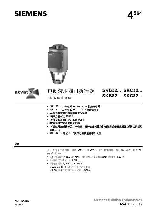
电动液压阀门执行器
行程 20 mm 或 40 mm
SKB32... SKC32... SKB82... SKC82...
• SK...32...: 工作电压 AC 230 V, 3 位控制信号 • SK...82...: 工作电压 AC 24 V, 3 位控制信号 • 执行器带有或不带有弹簧复位功能 • 调节力量可达 2800 N • 直接安装在阀门上,不需要调节 • 有手动调节和位置指示功能 • 可通过附加辅助开关、电位计、阀杆加热元件和机械行程逆变器来增强功能性(只适用
带有刻度盘 (4) 和行程指示的显示窗
6/10
Siemens Building Technologies HVAC Products
Hale Waihona Puke 电动液压阀门执行器CM1N4564CN 03.2003
维修 处置
当维修阀门时: • 关闭泵和电源,关闭管路系统中的主要阀门,卸掉系统压力,让系统完全冷却下来。
如果需要,拆掉电气连线。 • 阀门和执行器正确匹配时必须重新调试。
• Y2 上有电压: 旁通阀 (8) 打开,允许液压油通过复位弹簧(7)从压力腔(5) 流回储油池 (4) 中,阀杆(10) 伸长,阀头(11) 关闭。
• Y1 或Y2 上没有电压:执行器和阀门保持在目前行程位置。
SKB32.51, SKB82.51(U), SKC32.61和SKC82.61(U) 执行器,有弹簧复位特性,如果断电时,一秒钟旁通阀开启,弹簧复位。弹簧复位使执 行器回到«0%» 行程位置,关闭阀门,符合DIN 32730的安全要求。
1
阀门关闭
4
4
2
8
6
7
3 5
12
9
SK-3Q02G氢焰色谱分析仪使用说明书
样 品 气:入口→总烃样品气气阻→总烃 FID
切换电磁阀
助燃空气:入口→三通→空气稳压阀→点火气阻(点火电磁阀)→三通→总烃助燃空气气阻→ 总烃 FID
氢气燃气:入口→三通→总烃氢气稳压阀→总烃燃气气阻→总烃 FID
4.3.2.组份气路流程:
A. 分析,预切状态: 样 品 气:入口→组份样品气阻→注入阀(4)孔→(3)孔→十通转阀(1)孔→(2)孔→样气放空
最小检知浓度 50PPm 组份测量范围: 最小检知浓度~100%(甲烷)
最小检知浓度 30PPm 9. 重新修改了布局,增加了强制散热,提高了仪器的可靠性。 10. 提供多种标定方式,使用更加方便。
2.系统组成
SK-3Q02G 氢焰色谱仪与 SK-9G01 样品预处理单元组成了完整的分析系统。为了保证仪器的正 常工作,分析系统在相互连接时加了与其相关的净化系统,分析系统包括样品预处理单元、分析单 元。样品预处理单元采集来自泥浆脱气器的样品,通过样品泵,进入前处理系统,样品预处理单元 除了有样品气净化处理功能外,还有样品气分配功能,经处理或分配的样品气然后进入分析单元。 分析单元包括了采样系统、分离系统、检测器、流路控制系统、测控系统等。分析系统的方框图见 图 2-1;SK-9G01 的流程图见图 2-2。
iC5: 000000 nC5: 000000
显示内容:序号为 C1 到 nC5 是 C1~nC5 分析响应的峰保值(采样值 mV)。每分析一个周期就刷新。
4. SK-3Q02 氢焰色谱分析仪气路
4.1. 气路的组成
4.1.1. 样气气路方面 注入阀、稳压阀、各路气阻、样气气路管线等。
4.1.2. 氢气气路方面 氢气发生器、氢气稳压阀、各路气阻、氢气气路管线等。
ATS控制器操作说明

S K400系列双电源自动转换控制器操作说明1操作1.1操作面板1.2按键功能描述I路手动合闸键手动状态下,按键,I路接通负载。
分闸键手动状态下,按键,断开I路/II路负载。
II路手动合闸键手动状态下,按键,II路接通负载。
手动设置键按键,设置控制器为手动状态。
自动设置键按键,设置控制器为自动状态。
试机键按键,可以直接进入试机界面。
菜单键/确认键按键,进入菜单界面,长按键退出当前操作,回到主界面显示。
当控制器故障报警时,长按键,可消除故障报警。
翻屏键/增加键切换屏幕显示界面。
在参数配置界面调整参数时为数值增加键。
1.3主菜单界面在主界面下按下键,可进入主菜单界面。
按键选择不同的参数行(当前行反黑),再按进行确认,可进入相应的显示界面。
2参数配置在主界面下,按键,选择 1. 参数设置,再按键确定,则进入参数配置口令确认界面。
按键输入对应位的口令值0-9,按键进行位的右移,在第四位上按键,进行口令校对,口令正确则进入参数主界面,口令错误则直接退出返回主界面。
出厂默认口令为:1234。
按键可进行参数配置上下翻屏操作,在当前的配置参数屏下按键,则进入当前参数配置模式,屏幕第一行与当前值的第一位反黑显示,按键进行该位数值调整,按键进行移位,最后一位按键确认该项设置。
若设定的数值在范围内,则该值被保存到控制器内部的FLASH。
若超出范围,则不能被保存。
在参数配置界面,长按键,可直接退出该界面,回到主显示界面。
7.1参数配置表主要参数配置项目表参数名称整定范围默认值描述07 开关转换间隔(0-9999)秒1从一路分闸到二路合闸,或从二路分闸到一路合闸中间的延时等待时间24电流互感器变比(5-6000)/5500电流互感器参数2.定时开机3.日期时间设置控制器信息 一个分断位 0-06-25 (2) 10:00 参数名称 整定范围 默认值 描 述25 额定负载电流 (5-5000)A 500 机组额定电流28 设备编号 (1-254) 1 RS485通讯地址29 口令设置 1234 配置参数所需的密码值33切换优先级选择(1-3) 1 1.一路切换优先2.二路切换优先3.切换无优先 3 日期时间设置在主界面下,按键,选择3.日期时间设置,再按键确定,则进入日期时间设置界面。
SK5032说明书
大功率无线接警中心主机SK-5032使用说明书(安装和使用前必须详细阅读本书)目录一、概述----------------------------------------------3二、主要功能特点--------------------------------------3三、系统组成和工作原理--------------------------------4四、主要部件功能及用途说明----------------------------8五、系统安装编程与维护--------------------------------11六、日常值守人员操作指南------------------------------11七、故障检修------------------------------------------112一、概述SK-5032时刻大功率无线接警中心主机,是一种利用大功率无线远距离接收报警信息的智能设备。
配合大功率无线被动红外入侵探测器,可组成远距离无线防盗报警系统。
由于安装容易,操作便捷,防范范围广,特别适用于学校、厂房、博物馆、仓库、商场、档案室、居民小区及机关企事业单位内部作为防盗报警使用。
二、主要功能特点1、主机无线接收灵敏度可达?,配合时刻SK-170探头使用,无线接收距离最大可达?KM。
2、 32个无线防区,自动学习对码,每个防区可以对码学习两个不同编码地址的无线探头。
3、防区布撤防控制可以总布撤防,也可每个防区单独布撤防;并且每个防区可任意定义为禁止布防防区,键盘布撤防防区,定时/键盘布撤防防区和常布防防区;内置的电子时钟可实现每天两组定时布/撤防。
4、提供两组不同权限密码和一个编程开关,方便系统安装编程人员和日常值守人员分级灵活使用。
5、自动记录操作日志和报警信息,方便记录查询;6、内置大功率喇叭报警输出,?档音量可调节,最大可达?分贝;更有?种曲目可供选择。
7、内置免维护电池,智能充放电保护电路,交流电停电,仍可维持系统正常运行。
- 1、下载文档前请自行甄别文档内容的完整性,平台不提供额外的编辑、内容补充、找答案等附加服务。
- 2、"仅部分预览"的文档,不可在线预览部分如存在完整性等问题,可反馈申请退款(可完整预览的文档不适用该条件!)。
- 3、如文档侵犯您的权益,请联系客服反馈,我们会尽快为您处理(人工客服工作时间:9:00-18:30)。
名称
定 范 围(字)
说明
设备号 通讯波特率 报警打印功能
0~2 5 0 0~3 0~1
设定通讯时本仪表的设备代号
BA UD = 0: 通讯波 特率为1 200 B P S BA UD = 1: 通讯波 特率为2 400 B P S BA UD = 2: 通讯波 特率为4 800 B P S BA UD = 3: 通讯波 特率为9 600 B P S 无报警打印功能(无此功能时,无此参数) 有报警打印功能(无此功能时,无此参数)
第一输出零点
0~1. 2 00
第 一输出 零点 迁移量(见注2 )
5
名称 第一输出比例
设定范围(字)
说明
0~1. 20 0
第一输 出的放 大比 例(见注2)
第一输出下限
全量程
第一输出的下限量程
第一输出上限 第二输出方式 第二输出零点
全量程 0~2
0~1. 20 0
第一输出的上限量程
2 T=0: 外给定 变送输 出 2 T=1: 阀位反 馈值变 送输 出 2 T=2: 模拟控 制输出
第一报警回差
0~99 9 9
第一报警的回差值
第二报警回差
0~99 9 9
第二报警的回差值
第三报警回差
0~99 9 9
第三报警的回差值
第四报警回差
0~99 9 9
第四报警的回差值
比例带 积分时间
全量程
1~99 99 (×0.5 S)
比例带
积分时间 解除比例控制所产生的残留偏差 设 定为9 999时 ,积分 不起作 用
2) 在传 感 器与 端子之 间 接入 的任 何装置 ,都有 可能由 于 电 阻或 漏 流而影响测量精度。
热偶或高温计输入: 应采用与热偶对应的补偿导线作为延长线,最好有屏蔽。
RT D(铂 电阻) 输入: 三根 导线的 电阻必 须 相 同,每根 导线 电 阻不 能超过15Ω。
3、 通电 设 置 仪 表接 通 电 源后 进 入自 检(自检 状态见 下图),自检 完 毕后 ,仪 表
速坤仪表
S K系 列 智 能 数 显 仪
智能手动操作器
操作说明书
上海速坤仪器仪表有限公司
SHA NGHAI SUKUN INSTRUMENTS AND METERSCO,.LTD.
I SO 9 0 0 1
260
ISO 9001质 量管 理 体系 认证 企 业
产品质保期 本公司所销售的智能数显仪表系列产品质保期 为 自 发 货之日 起12个 月 , 质保 期 内 对 于 在 材料 和 制 造中有缺陷的产品给予免费维修或更换 ,购买者须 对产品的应用及功能选择负责 。质保期外的产品, 收取维修所需成本费。
自 动转入 工 作状 态, 在工作 状态下 ,按压 键 显示L OC, L OC参数 设置如下: 1) ① Lo c等 于 任意 参 数可 进 入一 级 菜单
(LO C =00;132时 无 禁锁) ② Lo c=132,按压 键4秒可 进 入二
级菜单; ③ Lo c=130,按压 键4秒可 进 入时
DC24V/2A(大) 见备注
≤30mA
综合参数
测量 精度 0. 2%FS 1字
设定方式 面板轻触式按键数字设定;参数设定值密码锁定;设定值断 电永久保存。
-1999~9 9 99外给 定显 示、 设定 值显 示、 控制 目标 值显 示,
显示 方式 0~1 0 0 %输出 量显 示, 双光 柱测 量值 、阀 位反 馈至 (或 输出
输入 输入信号
电流
电压
电阻
电偶
输入 阻抗 ≤2 5 0Ω
≥5 0 0KΩ
输入电流 最大限制
30mA
输入电压 最大限制
<6 V
输出
输出信号
电流
电压
继电器
24V配电或馈电
输出时 允许负载
≤5 0 0Ω
≥2 50 KΩ(注: 需要更高负载 能力是需更换 模 块)
AC220V/0.5A(小) DC24V/0.5A(小) AC220V/2A(大)
一、产品简介
XM S□3系 列 手动 操 作器 具 备多 类型输 入、输 出功能 ,可在 线修 改 仪表的信号类型;可与各类传感器、变送器配合使用,实现对温度、 压力、液位、容量、力等物理量的测量显示;并配合各种执行器对 电磁阀、电动调节阀、变频器等设备进行控制、报警控制、数据采 集等功能。
二、技术参数
目录
一、产品简介 …… ……… …………………………………… ………1 二、技术参数 …… ……… …………………………………… ………1 三、功能设置 …… ……… …………………………………… ………2 四、接线方式 …… ……… …………………………………… ………12 五、选型编码 …… ……… …………………………………… ………15
表将自动回到实时测量状态。 4、 参 数 设 置 1) 一 级 参 数 设 置
在 工 作状 态 下, 按压 键PV显 示LO C,SV显 示参 数 数值 :按 或 键 来 进行 设 置, 长按 键2秒 可返回 上一 级 参数 ,Loc等 于任 意参 数可进入一级参数。
▲ ▲
名称 设定参数禁锁
设定范围(范围)
1 DP= 0:无小 数点 1 DP= 1: 小数 点在十 位(显 示X X X .X) 1 DP= 2: 小数 点在百 位(显 示X X . XX) 1 DP= 3: 小数 点在千 位(显 示X . X XX)
3
▲
前 时间 显示 状 态下, 再次 按 压 键, 则 退出 时间设 定,回 至PV测 量 值显示状态。 ★返回工作状态 1)手动 返回: 在仪 表参 数 设定模 式下, 按压 键4秒后.仪 表即 自动
回到实时测量状态。 2)自动 返回: 在仪 表参 数 设定模 式下, 不按 任何按 键,3 0秒后 , 仪
量)显示,发光二级管工作状态显示
使用 环境 环境 温度 :0~5 0℃; 相对 湿度 :85%RH;避 免强 腐蚀 气体
工作 电源 A C1 00~2 4 0 V (开关 电源),5 0~60 Hz;DC 20~29 V(开关 电源)
功 耗 ≤4 W
结构 标准卡入式
通讯
采用 标准M O DB US通讯 协议 ,RS -4 85通 讯距 离可 达1公 里; R S- 23 2通 讯距 离可 达:1 5米。
公司其他产品:
1. 智能数显仪表、无纸记录仪系列 2. 单色液晶仪表、智能电工仪表系列 3. 差压、压力传感器变送器系列 4 . 各类 温湿度 传感器/变 送器 5. 各类热电阻、热电偶、一体化温度变送器 6. 节流装置、涡街流量计、电磁流量计系列 7. 玻璃转子、金属转子、蒸汽流量计系列 8. 各类气体计量柜、控制柜 9. 配套工控系统软件
说明
L OC=00:无禁锁(一级参数可修改)
0~99 9
L OC≠0 0,13 2:禁锁 (一级 参数 不可修 改)
L OC= 13 2:无 禁锁( 一级参 数、二 级参 数可修 改)
第一报警值
0~99 9 9
第一报警的报警设定值
第二报警值
- 1999~99 9 9 第 二报 警的报 警设定 值
第三报警值
第二输 出零点 迁移 量(见注2)
第二输出比例
0~1. 20 0
第二输 出的放 大比 例(见注2)
第二输出下限
全量程
第二输出的下限量程
第二输出上限
全量程
第二输出的上限量程
外给定输入分度号
外给定小数点位置
外给定单位 外给定闪烁报警 外给定滤波系数
0~3 5
0~3
0~4 5 0~1 0~19次
外给定 设定输 入分 度号类 型(见 分度号 类型表)
1
备注: 1、 仪表 带通讯 功能时 ,通 讯转换器最好选用 有源转 换器。 2、 外形 尺寸 为D、E的 仪表 继 电器 输出时 允许 负 载能 力为A C 2 20 V / 0 .5 A,D C2 4 V / 0. 5 A
三、功能设置
1、仪 表面 板
P V显 示 窗 S V显 示 窗
报警指示灯 确认键 移位键 减少键 增加键
间 设 置菜 单,对 于 带打印 功能 的表。 ④ Lo c等于 其它值 ,按压 键4秒 退
出到测量画面。 2) 如果L oc=5 77, 在Loc菜 单下 , 同时
按 住 键 和 键达4秒, 可以将 仪 表 的所有参数恢复到出厂默认设置。 3) 在其 它 任何 菜单下 , 按压 键4秒可 退出到测量画面。 4) 时间 设 定 在 仪表PV显 示测量 值的状 态下, 按 压 键 进 入参 数 ,设 定LOC = 13 0,在P V显示LOC,S V显 示130的状 态 下 ,按 压 键4秒,即 进入时 间 参数设 定 ,仪 表PV显 示“dATE”,SV显 示当 前 日期 (如:09072 0 -- 2009年7月20日), 在 此状 态下 ,可参 照仪表 参数设 定 方 法, 设 定 当 前日期 。 在仪 表当 前 日期 显示状 态下, 按 压 键 , 仪表P V显 示 “TlnE” , 仪表SV将显 示当 前时间 ( 如1 83047 -- 18点30分4 7秒) , 在此状态下,可参照仪表参数设定方法,设定当前时间。在仪表当
在点动输出时,可以实现阀位点动关小
增加键:用于增加数值
带打印功能时,用于手动打印
在点动输出时,可以实现阀位点动开大
2、仪 表配线
仪表在现场布线注意事项:
PV 输 入 (测 量 输入)
2
1) 减小 电 气干 扰,低 压 直流 信号 和传感 器输入 的连线 应 远 离强 电 走线。如果做不到应采用屏蔽导线,并在一点接地。
打印间隔时间
1~2 400分
